

Page 1
FIELDWARE for SMARTPAD II
S
H
I
F
T
C
T
R
L
2
N
D
A
L
T
C
A
P
S
C
H
G
L
O
W
B
A
T
Quick Start Guide
COMPACTFLASH CARD 256MB
CompactFlash
MB
256
Bulletin 98-01122
R3
BACKLIGHT DIM
BACKLIGHT BRIGHT
LIGHTBAR DIM
San Disk
SHIFT
CTRL
2ND
ALT
CHG
LOW
CAPS
BAT
UP ARROW
DOWN ARROW
RIGHT ARROW
LEFT ARROW
LIGHTBAR BRIGHT
ENTER
CENTER SCREEN
EXIT
BACKLIGHT ON/OFF
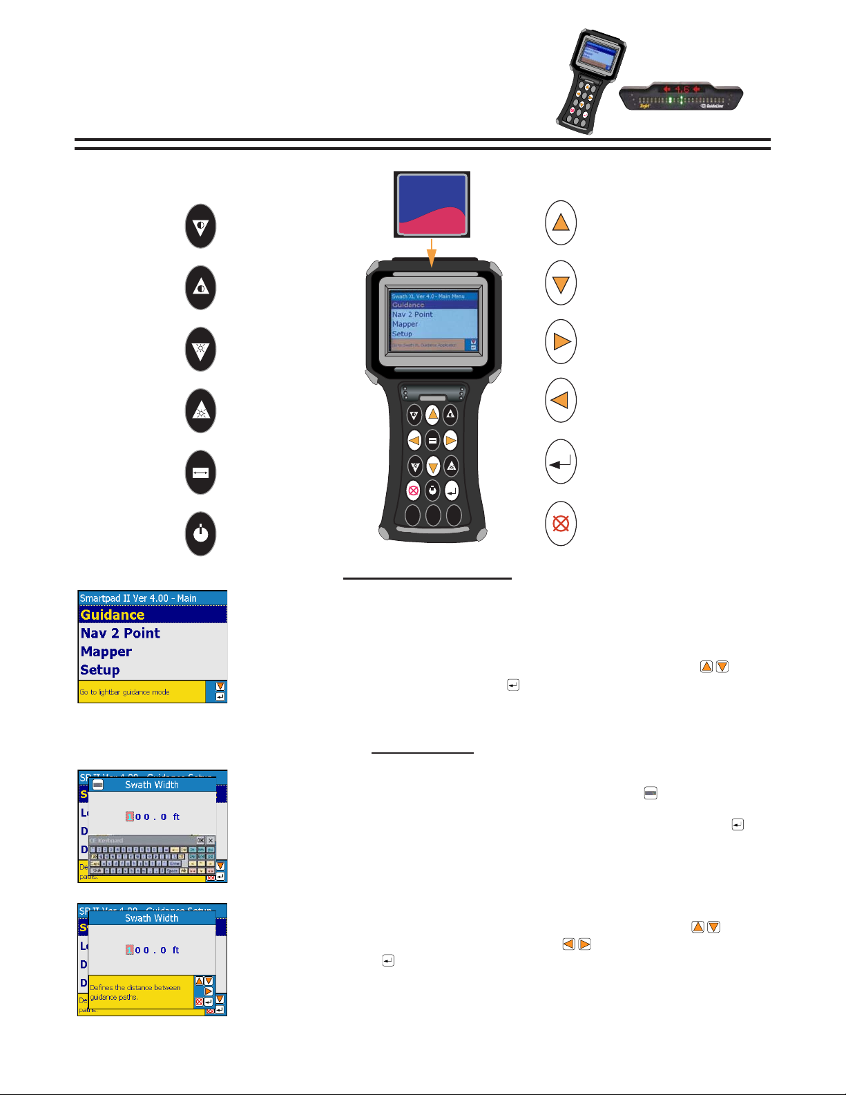
SCREEN SELECTION
TOUCH SCREEN SELECTION
To make a selection use a stylus and single tap the screen on the desired menu.
MANUAL SELECTION
Items can only be selected when highlighted. Use the Up and Down arrows to
highlight the desired selection. Press Enter to select.
DATA ENTR Y
ON-SCREEN KEYBOARD ENTRY
Select the desired menu to be changed. Select the Keyboard icon to bring up the on
screen keyboard. This icon will appear is the upper left corner of the screen only when
text can be entered. Select the desired character using a stylus and press Enter to
accept.
MANUAL ENTRY
Select the desired menu to be changed, and use the Up and Down arrows to
change the character. Use the Lef t and Right arrows to advance to the next
character. Press Enter to accept.
1
Page 2
Bulletin 98-01122
R-A-M
R3
Lightbar
Suction Cup Mount
(Optional)
64-05006
12v+
(NOT USED) INPUT 1
WHEN STATUS DETECT IS ON
12v+ MUST BE SUPPLIED TO
INPUT 2 WHEN APPLYING
+V
1
2
RED
GREEN
BLUE
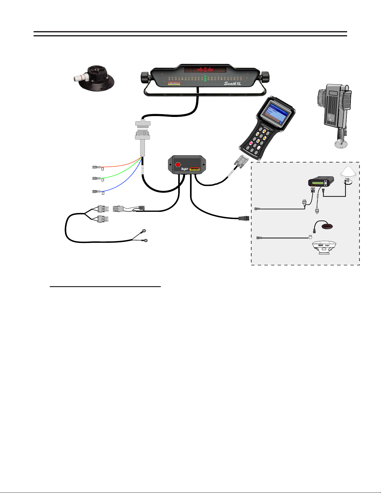
INSTALLATION GUIDE
Lightbar
MT - 78-50058
TJ - 78-50075
Smartpad II
75-30005
Smartpad II Interface
78-05050
SMARTPAD
POWER
INTERFACE
®
5 Amp
S
H
IFT
C
T
R
C
L
H
L
G
O
W
B
A
T
2
N
D
A
L
C
T
A
P
S
Adapter Cable
45-05337
for Smartpad II
15’
Ram Mount
(Optional)
65-05108
RX 400p GPS Receiver
& Antenna
78-50062
H
igh
RX 400p
RX 400p
Di
f
f
e
ren
Lat
5
1
00.
120
Lon
1
1
202.
2
M
I
D
T
E
C
H
Midwest Technologies, Inc.
Inline Fuse
R
-A
-M
A
cc
ur
acy
tia
l GP
S R
e
ce
iv
er
N+
ENTER
5
0
W
H
11/
2
Amp
Power Cable
12'
45-05298
Battery
GPS Data Cable
45-05338
15’
RX 350p
GPS Receiver
78-50104
RX 360p
GPS Receiver
78-50105
INSTALLATION INSTRUCTIONS
1. The Lightbar can be mounted inside or outside the cab. The lightbar is weather proof but not resist ant
to high water pressures.
2. The GPS antenna must be mounted with a clear view of the sky. The tallest point on the vehicle is
preferred. When using a 2-way radio the GPS antenna and cables should be mounted as far away as
possible from the 2-way antenna and cables.
3. Midwest Technologies recommends that the power source come directly from the battery.
4. When using an existing switch in the cab to signal to the SmartPad that the application has begun,
two things must be done.
A. On the SmartPad under the guidance setup menu locate Status Detect
Status Detect - This must be set to 1 Section. See Page 5 of this bulletin.
B. See diagram above. When St atus Detect is set to 1 Section 12v+
must be supplied to Input 2 when applying. Connect Input 2 (Blue Wire)
to the switched12v+ side of the master switch when the implement is applying.
2
Page 3
WHAT’S NEW WITH
Bulletin 98-01122
SMARTPAD II
General
- Touch screen
- Uses Compact Flash storage cards
- Uses existing Swath XL and Guideline interface and lightbar
- Software now called “Fieldware for the Smart Pad II”
- Pop up keyboard for touch screen entry of names and values
- View and delete files from card
- Adjust brightness and backlight with keys on keypad
- Added “Pan” feature allowing users to move around and zoom in on the map in real time with key strokes
- Touching objects in real time brings up the object’s info
- E-Dif ready
- Added a “GPS Logger” application under Tools to log raw GGA output from a receiver
Nav-2-Point
- View GMF files as background
- Show BND files as background
- Last visited sample point is “remembered” eliminating need to scroll to next sample number
Guidance
- As Applied dat a can now be viewed in Solid view or Boom Pattern view
- Curved AB now a guidance type
- Guidance T ype now selected in real time menu
- Distance to next pass information displayed on lightbar
- Verification before creating a new guideline when one already exists
- Can now collect where-applied data without lightbar connected
- Last guidance type selected now remembered on exit and for next job
- GPS T ype and GPS Data Rate are now selectable during setup
- Antenna Height for tilt sensor option
R3
Mapper
- Mapper now added as an application
- Allows mapping of points, hazards, lines, polygons and boundaries
S
H
I
F
T
2
N
D
C
T
R
L
A
L
T
C
H
G
L
O
W
C
A
P
S
B
A
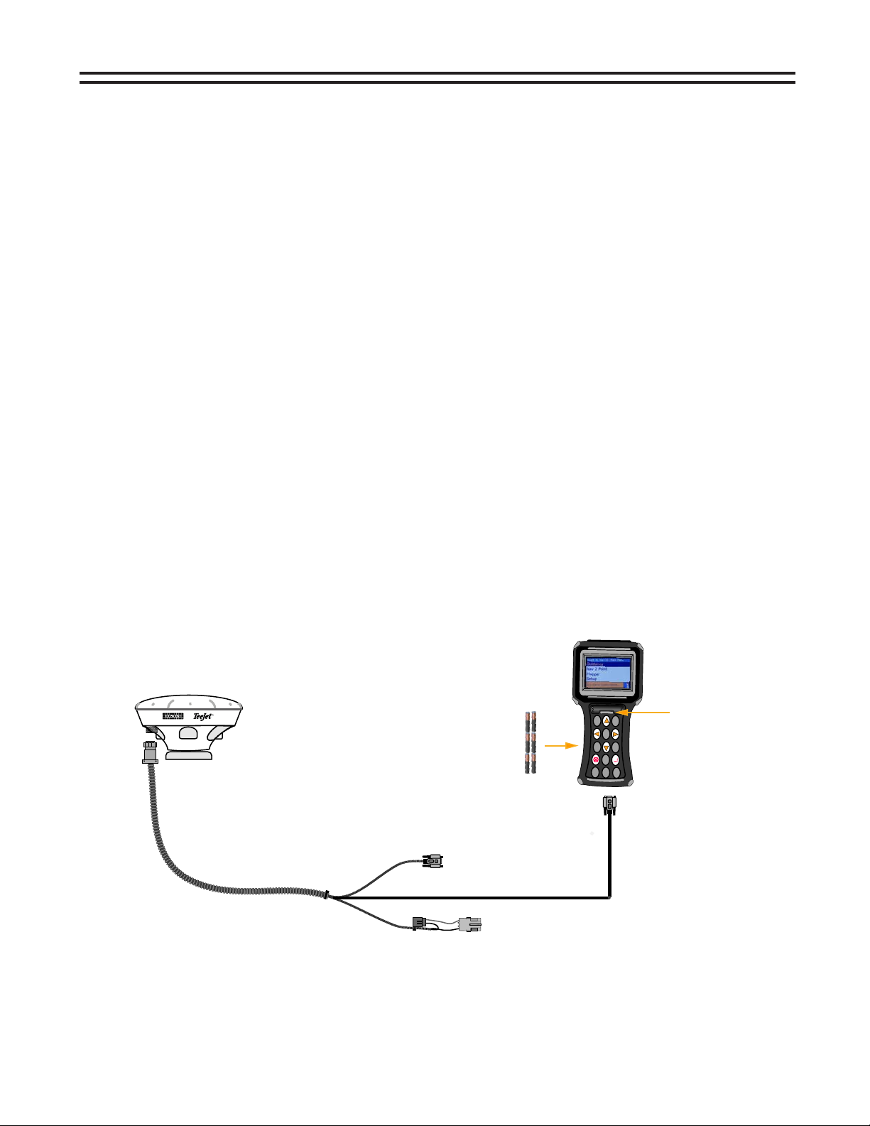
78-50105
RX 360p
GPS Receiver
(6) AA Batteries
Powers SmartPad
T
Not included in kit
Port B
19200
45-05350
GPS Data/Power Cable
Port A
4800
GGA 1HZ
GGA 5HZ
VTG 1Hz
(DB9)
VTG 1HZ
(DB9)
12v+ Power
GPS Receiver
The illustration above shows one of the new features of the SmartPad II. This configuration makes the system
very mobile and easy to transfer for off-season mapping opportunities including field boundaries, tile lines, hazards, and many other items that may fit your application. It is not necessary to use the smartpad interface or the
lightbar with the mapper application. The SmartPad II can be powered using six AA batteries and the only power
needed is 12v+ to the receiver.
Power Button
when using Batteries
3
Page 4
Bulletin 98-01122
R3
GETTING STARTED
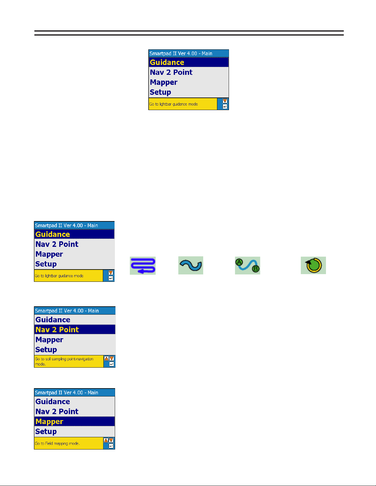
MAIN LAUNCHER
The Main Launcher is the first menu page you see after powering up the SmartPad II. This is the top menu page
and from here you can launch an application. The Fieldware for SmartPad II software is made up of three software applications (programs), Guidance, Nav2Point, and Mapper. Each application can be broken down into two
main components, Setup and Real-Time Mapping. Use the next few p ages to see the Setup structure and Realtime buttons for the application you choose to use. Review all setup settings and make changes as needed.
Remember to use the on screen help window to determine what data should be entered.
Example: Entering the Swath Width in the Guidance application: See page 5 (this is the flow chart for the guidance application) follow the chart to Swath Width. Notice that Guidance is selected from the main launcher
screen, then select Setup, and the final step would be to select Guidance. From this point Swath Width is one of
items that should be setup before starting guidance. This procedure is the same for all three applications (Guid-
ance, Nav2Point, and Mapper) each application has its own flow chart.
The Guidance application provides the operator with clear and intuitive steering
assistance as well as real-time application information. The operator can
select between four different guidance modes:
Parallel Curved Curved A-B Center Pivot
The Nav2Point application allows you to navigate to specific predetermined
point locations, or to more generalized areas of a field, based on various types
of background data such as yield or soil maps. Once at the desired location,
add that location as a sample point and assign a point number and location
name. The primary use of the Nav2Point application will be for soil sampling.
The Mapper application allows the operator to map field boundaries, weed
patches, insect infestation, ponds, water ways, rocks, tile lines, as well as
many other features you feel are important to your operation. Features can
be mapped as points, lines, or polygons.
4
Page 5

GUIDANCE SETUP
Bulletin 98-01122
R3
GUIDANCE
START GUIDANCE
SETUP
AS APPLIED FILE
GUIDELINE FILE
BOUNDARY
MAP OBJECT
GO
GUIDANCE
These menus will not appear if the items under DATA
are turned off. No data will be stored to the card.
Note: The card is not need to obtain guidance. When
the card is not used all menus under DATA must be off.
SWATH WIDTH
LOOK AHEAD
DIR TO SWATH
DIS TO SWATH
ANT. HEIGHT
STATUS DETECT
GPS TYPE
GPS DATA RATE
DATA
LIGHTBAR
AS APPLIED
BOUNDARY
MAP OBJECT
LIGHTBAR
DRIVE SENSITIVITY
DISPLAY MODE
PARALLEL Msg 1
PARALLEL Msg 2
PARALLEL Msg 3
CURVED Msg
LED BRIGHTNESS
ALARM
HAZARD RANGE
USE THE ON BOARD HELP MENU FOR
INSTRUCTIONS OR DESCRIPTION OF ITEM SELECTED
!!
5
Page 6

Bulletin 98-01122
R3
REAL-TIME GUIDANCE BUTTONS
REAL-TIME GUIDANCE DEFAULT BUTTONS
Mark A - This button is used with Parallel and Curved A-B guidance. This
button is pressed to mark the first end point of the initial guideline.
Mark B - This button is used with Parallel and Curved A-B guidance. This
button is pressed to mark the end point of the initial guideline.
New Guideline - This button will appear after the initial guideline has
been created. When pressed this SamartPad II will ask for a new
guideline, if accepted Mark A button will appear.
Mark A Circle Pivot - This button is pressed to mark the first end point
of the initial circle guideline.
Mark B Circle Pivot - This button is pressed to mark the end point of
the initial circle guideline.
Mark B Circle Pivot Wait - This button appears when the Mark A Circle
Pivot has been pressed and the software is collecting enough points
(approximately 12 seconds) to describe a circle. After this time period
the Mark B Circle Pivot button will appear.
Zoom In - When pressed this button decreases area displayed in the
view page. There are a total of 5 zoom levels.
Zoom Out - When pressed this button increases area displayed in the
view page. There are a total of 5 zoom levels.
Applied Swath Off - When this button is displayed, the spray or
spreader is Off. When pressed this button changes to Applied Status On
button.
Applied Swath ON - When this button is displayed, the spray or spreader
is On. When pressed this button changes to Applied Status Off button.
Note: When using Status Detect this button will change automatically.
Map Field Boundary Off - When this button is displayed, the field
boundary is not being mapped. When pressed this button changes to
the Map Field Boundary On Button.
Map Field Boundary ON - When this button is displayed, the field
boundary is being mapped. When pressed this button changes to the
Map Field Boundary Off Button.
Mark Point - This is the point map object button. When pressed, a
pointis placed at the vehicle location. This button is a result of the Data
Setup - Map Object menu item.
Mark Hazard - This is the hazard map object button. When pressed, a
hazard placed at the vehicle location. This button is a result of the Data
Setup - Map Object menu item.
Full Screen - When Pressed, the entire view page space is replaced by
the map window. This is useful to see more of the vehicle trajectory.
Press exit to return to the normal view page.
REAL-TIME GUIDANCE PATTERNS
Parallel Straight A-B - This button indicates the current guidance
pattern in Parallel. Pressing this button will bring up the other
guidance mode buttons as shown in this section.
Curved - This button indicates the current guidance pattern in
Curved. Pressing this button will bring up the other guidance
mode buttons as shown in this section.
Circle Pivot - This button indicates the current guidance pattern in
Circle Pivot. Pressing this button will bring up the other guidance
mode buttons as shown in this section.
Curved A-B - This button indicates the current guidance pattern in
Curved A-B. Pressing this button will bring up the other guidance
mode buttons as shown in this section.
REAL-TIME ZOOM AND PAN
Zoom Pan Mode - When pressed this button will enter into Pan
mode. The buttons below will appear and can be used to pan the
screen Up, Down, Left, and Right.
Pan Up - When pressed this button will scroll to the collected data
at the Top of the screen
Pan Down - When pressed this button will scroll to the collected
data at the Bottom of the screen
Pan Left - When pressed this button will scroll to the collected
data on the Left side of the screen
Pan Right - When pressed this button will scroll to the collected
data on the Right side of the screen
Snap - When pressed the screen will zoom out to its fullest extent
allowing view of the entire working area.
Zoom In - When pressed this button decreases area displayed in
the view page. There are a total of 5 zoom levels.
Zoom Out - When pressed this button increases area displayed in
the view page. There are a total of 5 zoom levels.
Exit Pan Mode - When pressed Pan Mode is exited and the Zoom
Pan Mode button will be highlighted.
REAL-TIME OPTIONS MENU
Information - When this button is highlighted, information is displayed
in the information window and on the screen.
Locked Information - When this button is displayed, it mean that the
Information Button was pressed. Information stays displayed in the
Information Window while moving to other buttons in the button bar.
Exit - When pressed, the software exits out of real-time process and
returns to the Start Guidance page. Pressing the key automatically
highlights this button.
Option Menu - When pressed, the real-time display options are
displayed. The options are listed below.
North Up View - This display option keeps North pointing to the
top of the view page. When pressed, this button changes to the
COG View button.
Course on Ground (COG) View - This display option keeps the
vehicle stationary in the view page with the heading (course) of the
vehicle pointing to the top of the view page. When pressed, this
button changes to the North Up View button.
Boom Applied View - This drops bars representing the boom
where applied. This view can help show overlap. When pressed,
this button changes to the Solid Applied View button.
Solid Applied View - This colors a solid path of where applied.
This view can help show skips. When pressed, this button changes
to the Boom Applied View button.
Exit Options Menu - When pressed the Option Menu is exited and
the Option Menu button will be highlighted.
6
Page 7

Nav2Point SETUP
Bulletin 98-01122
R3
Nav2Point
START Nav2Point
SETUP
POINT/GRID FILE
BACKGROUND
BOUNDARY
GO
LIGHTBAR
ANTENNA
These menus will not appear if the items under DATA
are turned off. No data will be stored to the card.
LIGHTBAR
LED BRIGHTNESS
ALARM
ALARM RANGE
DISPLAY MAG
OFFSET DIRECTION
OFFSET DISTANCE
DATA
POINT/GRID FILE
BOUNDARY
BACKGROUND
SAMPLE #
SAMPLE NAME
USE THE ON BOARD HELP MENU FOR
INSTRUCTIONS OR DESCRIPTION OF ITEM SELECTED
!!
7
Page 8

Bulletin 98-01122
R3
REAL-TIME Nav2Point BUTTONS
REAL-TIME Nav2Point DEFAULT BUTTONS
Add Sample - When pressed a sample point is dropped at the antenna
offset position. The user is prompted for sample number and name,
depending on how Data Setup is configured.
Delete Sample - The user must be over (very close to) an existing
sample point. Once pressed the sample point is removed from the view
and data file.
Start Navigation - Press this button to select and navigate to an existing
point. Once pressed this button changes to Stop Navigation button.
Stop Navigation - This button appears when the Start Navigation button
has been pressed. Once pressed, the current navigation to an existing point
is stopped and this button changes back to the Start Navigation button.
Edit Sample - The user must be over (very close to ) an existing sample
point. Once pressed, a dialog containing the sample number and name
appears. The user is able to edit these two sample point attributes.
Zoom In - When pressed this button decreases area displayed in the
view page. There are a total of 5 zoom levels.
Zoom Out - When pressed this button increases area displayed in the
view page. There are a total of 5 zoom levels.
Map Field Boundary Off - When this button is displayed, the field
boundary is not being mapped. When pressed this button changes to
the Map Field Boundary On Button.
Map Field Boundary ON - When this button is displayed, the field
boundary is being mapped. When pressed this button changes to the
Map Field Boundary Off Button.
Mark Point - This is the point map object button. When pressed, a
pointis placed at the vehicle location. This button is a result of the Data
Setup - Map Object menu item.
Mark Hazard - This is the hazard map object button. When pressed, a
hazard placed at the vehicle location. This button is a result of the Data
Setup - Map Object menu item.
Full Screen - When Pressed, the entire view page space is replaced by
the map window. This is useful to see more of the vehicle trajectory. Press
exit to return to the normal view page.
REAL-TIME ZOOM AND PAN
Zoom Pan Mode - When pressed this button will enter into Pan
mode. The buttons below will appear and can be used to pan the
screen Up, Down, Left, and Right.
Pan Up - When pressed this button will scroll to the collected data
at the Top of the screen.
Pan Down - When pressed this button will scroll to the collected
data at the Bottom of the screen.
Pan Left - When pressed this button will scroll to the collected
data on the Left side of the screen.
Pan Right - When pressed this button will scroll to the collected
data on the Right side of the screen.
Snap - When pressed the screen will zoom out to its fullest extent
allowing view of the entire working area.
Zoom In - When pressed this button decreases area displayed in
the view page. There are a total of 5 zoom levels.
Zoom Out - When pressed this button increases area displayed in
the view page. There are a total of 5 zoom levels.
Exit Pan Mode - When pressed Pan Mode is exited and the Zoom
Pan Mode button will be highlighted.
Information - When this button is highlighted, information is displayed
in the information window and on the screen.
Locked Information - When this button is displayed, it mean that the
Information Button was pressed. Information stays displayed in the
Information Window while moving to other buttons in the button bar.
Exit - When pressed, the software exits out of real-time process and
returns to the Start Guidance page. Pressing the key automatically
highlights this button.
REAL-TIME OPTIONS MENU
Option Menu - When pressed, the real-time display options are
displayed. The options are listed below.
North Up View - This display option keeps North pointing to the
top of the view page. When pressed, this button changes to the
COG View button.
Course on Ground (COG) View - This display option keeps the vehicle
stationary in the view page with the heading (course) of the vehicle pointing
to the top of the view page. When pressed, this button changes to the
North Up View button.
Exit Options Menu - When pressed the Option Menu is exited and
the Option Menu button will be highlighted.
8
Page 9

MAPPER SETUP
Bulletin 98-01122
R3
MAPPER
START MAPPER
SETUP
MAP FILE
BOUNDARY FILE
GO
ANTENNA
DATA
This menu will not appear if the item under DATA
is turned off.
OFFSET DIRECTION
OFFSET DISTANCE
BOUNDARY
USE THE ON BOARD HELP MENU FOR
INSTRUCTIONS OR DESCRIPTION OF ITEM SELECTED
!!
9
Page 10

Bulletin 98-01122
R3
REAL-TIME MAPPER BUTTONS
REAL-TIME MAP OBJECT BUTTONS
Polygon Mark - Used to map or locate features that can be represented
by a closed shape made of discrete points. When pressed the Map Object
buttons change to Mark Polygon Point button. Press to mark a point along
the polygon perimeter. When finished press the Finish Flag button.
Polygon Stream - Used to map or locate features that can be represented
by a closed shape made up of streaming points.
Object buttons changes to the Finish Flag button. Press the Finish Flag to
close the polygon.
Polyline Mark - Used to map or locate features that can be represented by a
line of discrete points. When pressed the Map Object buttons change to
Mark Polyline Point button. Press to mark a point along the polyline. When
finished press the Finish Flag button.
Polyline Stream - Used to map or locate features that can be represented
by a line of streaming points.
changes to the Finish Flag button. Press the the Finish Flag to close the polygon.
Mark Polygon/Polyline Point - Used to mark points only when Polygon
Mark or Polyline Mark button is selected. This button goes away after the
Finish Flag button is selected.
Finish Flag - Used to exit out or close Map Object operations. When
pressed all Map Object buttons appear.
When pressed the Map Object buttons
REAL-TIME MAPPER DEFAULT BUTTONS
Mark Point - This is the point map object button. When pressed, a
pointis placed at the vehicle location. This button is a result of the Data
Setup - Map Object menu item.
Zoom In - When pressed this button decreases area displayed in the
view page. There are a total of 5 zoom levels.
When pressed the Map
REAL-TIME ZOOM AND PAN
Zoom Pan Mode - When pressed this button will enter into Pan
mode. The buttons below will appear and can be used to pan the
screen Up, Down, Left, and Right.
Pan Up - When pressed this button will scroll to the collected data
at the Top of the screen.
Pan Down - When pressed this button will scroll to the collected
data at the Bottom of the screen.
Pan Left - When pressed this button will scroll to the collected
data on the Left side of the screen.
Pan Right - When pressed this button will scroll to the collected
data on the Right side of the screen.
Snap - When pressed the screen will zoom out to its fullest extent
allowing view of the entire working area.
Zoom In - When pressed this button decreases area displayed in
the view page. There are a total of 5 zoom levels.
Zoom Out - When pressed this button increases area displayed in
the view page. There are a total of 5 zoom levels.
Exit Pan Mode - When pressed Pan Mode is exited and the Zoom
Pan Mode button will be highlighted.
Zoom Out - When pressed this button increases area displayed in the
view page. There are a total of 5 zoom levels.
Map Field Boundary Off - When this button is displayed, the field
boundary is not being mapped. When pressed this button changes to
the Map Field Boundary On Button.
Map Field Boundary ON - When this button is displayed, the field
boundary is being mapped. When pressed this button changes to the
Map Field Boundary Off Button.
Mark Hazard - This is the hazard map object button. When pressed, a
hazard placed at the vehicle location. This button is a result of the Data
Setup - Map Object menu item.
Full Screen - When Pressed, the entire view page space is replaced by
the map window. This is useful to see more of the vehicle trajectory. Press
exit to return to the normal view page.
Information - When this button is highlighted, information is displayed
in the information window and on the screen.
Locked Information - When this button is displayed, it mean that the
Information Button was pressed. Information stays displayed in the
Information Window while moving to other buttons in the button bar.
Exit - When pressed, the software exits out of real-time process and
returns to the Start Guidance page. Pressing the key automatically
highlights this button.
REAL-TIME OPTIONS MENU
Option Menu - When pressed, the real-time display options are
displayed. The options are listed below.
North Up View - This display option keeps North pointing to the
top of the view page. When pressed, this button changes to the
COG View button.
Course on Ground (COG) View - This display option keeps the vehicle
stationary in the view page with the heading (course) of the vehicle
pointing to the top of the view page. When pressed, this button
changes to the North Up View button.
Exit Options Menu - When pressed the Option Menu is exited and
the Option Menu button will be highlighted.
10
Page 11

LIGHTBAR INDEX
LIGHTBAR STATE DESCRIPTION
Mark A: Displayed when establishing the guidance point A of the initial
guideline.
Mark B: Displayed when establishing the guidance point B of the initial
guideline.
Swath #: A user selected lightbar message. When not on the initial
guideline the first character is either L or R for Left and Right of the initial
guideline. The number identifies how many lines left or right of the
initial guideline.
X-Track Error: A user defined lightbar message. This cross track error
message is displayed when the vehicle is on the guideline and there is
no error.
Bulletin 98-01122
R3
X-Track Error: A user defined lightbar message. In this example the
operator should steer to the left 2.3ft. (Assuming the system unit is set to
US and lightbar is set to Swath mode.)
Vehicle Heading Error: A user defined lightbar message indicating
the current heading error between vehicle heading and the bearing of
the guideline in degrees and decimal degrees. The arrow indicates
steering direction.
Ground Speed: A user defined lightbar message indicating the vehicle
speed in mile per hour (MPH). System unit is set to US.
Ground Speed: A user defined lightbar message indicating the vehicle
speed in kilometers per hour (KPH). System unit is set to Metric.
Course on Ground (COG): A user defined lightbar message indicating
the vehicles heading in degrees 0 to 359. The example to the left
indicates the vehicle’s course on the ground is due South (180 degrees).
Area Applied: A user defined lightbar message indicating the current
amount of area applied in acres. System unit is set to US.
Area Applied: A user defined lightbar message indicating the current
amount of area applied in hectares. System unit is set to Metric.
11
Page 12

Bulletin 98-01122
R3
LIGHTBAR INDEX
LIGHTBAR STATE DESCRIPTION
Applied Area Detection: This message is displayed when the vehicle is
with in a previously applied area. Note the Red stop lights are
illuminated. At this point an alarm will sound if the applied alarm setting
was turned on in the user setup.
Curved guidance information graphic. The four horizontal bars in the
text display represent a perspective view of the swath ahead of the
vehicle. The bars will skew left or right to represent the curved path
ahead.
Hazard Detection: The name of the hazard is displayed when the vehicle
is approaching an existing hazard. Note the yellow stop lights are
illuminated indicating the initial warning. Initial warning distance is
set in system setup under Hazard Range.
Hazard Detection: The name of the hazard is displayed when the vehicle
is approaching an existing hazard. Note the red stop lights are
illuminated indicating the final warning Final warning distance is
half the distance of the initial warning set in system setup under
Hazard Range.
Mapping Boundary: This message is displayed when the user is
mapping the field boundary. The arrow symbol on the left indicates
the field boundary is on the left side of the vehicle implement.
Mapping Boundary: This message is displayed when the user is
mapping the field boundary. The arrow symbol on the right indicates
the field boundary is on the right side of the vehicle implement.
System Warning: This message is displayed when there is a complete
loss of DGPS (differential GPS corrections). Guidance calculations
are stopped until differential corrections resume.
System Warning: This message is displayed when there is a complete
loss of GPS signal to the GPS receiver or SmartPad. Guidance calculations
are stopped until GPS signal resumes.
Lightbar Version Message: This message is displayed when the user
runs the Lightbar Test. M4 indicates the Lightbar model and the 2.0
indicates the lightbar protocol version number. This number varies and
is based on the lightbar version and model.
Point Number: This is displayed only when using the Nav2point feature.
Pt 3 indicates the number of the point the operator is navigating to.
12
Distance to Point: This is displayed only when using the Nav2Point
feature. The display indicates the distance to the point the user is
navigating to.
Midwest Technologies Illinois, LLC
2864 Old Rochester Rd. - Springfield, IL 62703
®
www.mid-tech.com www.teejet.com
 Loading...