

Page 1

RX 400p
User Guide
Midwest Technologies Illinois, LLC
2733 E. Ash St.
Springfield, IL 62703
Telephone number: 217-753-8424
Fax number: 217-753-8426
E-mail address: custserve@mid-tech.com
Web Site: www.mid-tech.com
98-05044
R1
Page 2

RX 400p
98-05044 2
R1
Page 3

RX 400p
Copyright Notice
Copyright 2001 Midwest Technologies Illinois, LLC. All rights reserved.
No part of this manual may be stored in a retrieval system, transmitted, or reproduced
by any means, including, but not limited to photocopy, photograph, digitizing, or
otherwise, without the prior written permission from MID-TECH Inc.
Trademarks
MID-TECH and the MID-TECH logo are registered trademarks of Midwest
Technologies Illinois, LLC. All other trademarks are the property of their respective
owners.
i 98-05044
R1
Page 4

RX 400p
MID-TECH Limited Warranty
MIDWEST TECHNOLOGIES ILLINOIS, LLC (herein called MID-TECH)
warrants to the original purchaser that the product purchased shall be free of defect in
material or workmanship. If the product proves to be defective within the warranty
period the purchaser must return, freight prepaid, said product to MID-TECH within
thirty (30) days after such defect is discovered. Upon inspection and examination by
MID-TECH, and at its option, MID-TECH shall repair or replace, with a new or
comparable product. No product will be considered defective if it substantially
fulfills the performance specifications. Purchaser shall be responsible for all required
maintenance service in accordance with procedures outlined in MID-TECH’s product
operator manual or service bulletins.
All product(s) replaced or repaired under warranty shall carry the remainder of the
warranty left on the original purchase. All out of warranty product(s) serviced for fee
or goodwill will have ninety (90) days of warranty. The ninety (90) days shall begin
on the date serviced by MID-TECH.
Warranty periods for MID-TECH products shall be:
MID-TECH Legacy Consoles – 2 ½ years
MID-TECH TASC Consoles – 2 ½ years
MID-TECH ARC Consoles – 2 ½ years
MID-TECH AgLogix Consoles – 2 ½ years
MID-TECH Switch boxes – 2 ½ years (3, 5, 9 boom)
All other MID-TECH products – 12 months (unless otherwise noted)
98-05044 ii
R1
Page 5

RX 400p
WARRANTY LIMITATIONS AND EXCLUSIONS
MID-TECH will have no warranty obligation hereunder if the product is subjected to
abuse, misuse, improper or abnormal usage, acts of God, faulty installation, improper
maintenance as outlined in MID-TECH’s product operator manual or service
bulletins. Consumable items (items that are used during normal operation) such as
light bulbs, batteries, etc., and expendable items (items which wear out in normal
use) such as injection pump tubes, flow meter bearings, etc., will not be covered by
warranty. For products that come in direct contact with chemical, the specific
recommendations contained in MID-TECH product bulletins must be adhered to, or
this warranty is void. Any repairs or alterations, other than those provided by MIDTECH and/or its authorized representatives, will void the warranty. MID-TECH
neither assumes nor authorizes anyone to assume for it any other obligation or
liability in connection with said product.
DISCLAIMER OF UNSTATED WARRANTY
The warranty printed above is the only warranty applicable to this purchase. MIDTECH’s warranty cannot be modified by any person or entity, including without
limitation, any distributor or retailer of MID-TECH. All other warranties, express or
implied, including but not limited to, the implied warranties of merchantability and
fitness for a particular purpose, are disclaimed.
LIMITATION OF LIABILITY
It is understood and agreed that MID-TECH’s liability, whether in contract, in tort,
under any warranty, in negligence or otherwise, shall not exceed the return of the
amount of the purchase price paid by purchaser and under no circumstances shall
MID-TECH be liable for special, indirect or consequential damages. In particular,
MID-TECH shall not be liable for damage to crops as the result of misuse or
negligence in the application of chemicals or operation of MID-TECH products. The
price stated for the equipment is a consideration in limiting MID-TECH’s liability.
No action, regardless of form, arising out of the transactions under this agreement
may be brought by purchaser more than one year after the cause of action has
occurred.
iii 98-05044
R1
Page 6

RX 400p
MID-TECH does not warrant or guarantee the precision or accuracy of positions
obtained when using MID-TECH products. Product accuracy as stated in MIDTECH literature and/or product specifications serves to provide only an estimate of
achievable accuracy based on:
Specifications provided by the US Department of Defense (US DoD) for
GPS Positioning,
GPS OEM Receiver specifications of the appropriate manufacturer (if
applicable),
DGPS service provider performance specifications
MID-TECH reserves the right to modify MID-TECH products without any obligation
to notify, supply or install any improvements or alterations to existing products.
98-05044 iv
R1
Page 7

RX 400p
Table of Contents
List of Figures............................................................................................................. xi
List of Tables .............................................................................................................xii
Preface.......................................................................................................................xiii
Organization ......................................................................................................xiv
Customer Service................................................................................................xv
World Wide Web Site .......................................................................................xvi
Document Conventions ....................................................................................xvii
Notes, Cautions, and Warnings ........................................................................xvii
Installation .......................................................................................................1-1
1
1.1 System Parts List......................................................................................1-1
1.2 Receiver Layout and Connections............................................................1-1
1.3 Installing the RX 400p Receiver ..............................................................1-2
1.3.1 Receiver Placement......................................................................1-2
1.3.2 Environmental Considerations.....................................................1-3
1.3.3 Power Considerations ..................................................................1-3
1.3.4 Turning the RX 400p On .............................................................1-4
1.3.5 Grounding the RX 400p ..............................................................1-4
1.3.6 Connecting the RX 400p To External Devices............................1-4
1.4 Installing the CDA-2B Antenna...............................................................1-7
1.4.1 Antenna Placement To Optimize Beacon Reception ...................1-7
1.4.2 Antenna Installation – 1-14-UNS Threaded Mount ....................1-8
1.4.3 Antenna Installation – Surface Mount .........................................1-8
1.4.4 Routing and Securing the Antenna Cable....................................1-9
v 98-05044
R1
Page 8

RX 400p
Connecting the CDA-2B Antenna .............................................. 1-9
1.4.5
1.5 Mounting Accessories ........................................................................... 1-11
1.5.1 Magnetic Mount........................................................................ 1-11
1.5.2 Survey Adapter ......................................................................... 1-11
2 RX 400p Overview.......................................................................................... 2-1
2.1 GPS Operation......................................................................................... 2-1
2.1.1 Automatic Tracking .................................................................... 2-1
2.1.2 Receiver Performance................................................................. 2-1
2.2 WAAS Operation .................................................................................... 2-2
2.2.1 Automatic Tracking .................................................................... 2-2
2.2.2 Receiver Performance................................................................. 2-2
2.3 OmniSTAR Operation............................................................................. 2-3
2.3.1 Automatic Tracking .................................................................... 2-3
2.3.2 Receiver Performance ................................................................. 2-3
2.4 Beacon Operation.................................................................................... 2-4
2.4.1 Tune Modes ................................................................................ 2-4
2.4.2 Receiver Performance ................................................................. 2-6
2.5 Factory Default Parameters ..................................................................... 2-7
3 RX 400p Architecture .................................................................................... 3-1
3.1 Hardware ................................................................................................. 3-1
3.2 Firmware ................................................................................................. 3-1
3.3 Applications ............................................................................................ 3-2
4 Operation......................................................................................................... 4-1
4.1 Front Display and Keypad....................................................................... 4-1
4.2 Navigating the Menu System .................................................................. 4-2
4.3 Menu Access Icon ................................................................................... 4-2
98-05044 vi
R1
Page 9

RX 400p
Receiver Status Icons ...............................................................................4-2
4.4
4.4.1 Position Fix Status Icon ...............................................................4-3
4.4.2 WAAS Lock Icon ........................................................................4-3
4.4.3 OmniSTAR Lock Icon.................................................................4-4
4.4.4 Beacon Lock Icon ........................................................................4-5
4.4.5 External DGPS Correction Source Icon ......................................4-5
4.4.6 Autonomous Mode Icon ..............................................................4-6
4.5 RX 400p Menu System Overview ...........................................................4-6
4.6 Start-Up Sequence..................................................................................4-11
4.7 Signal Tracking Bar Chart......................................................................4-11
4.7.1 WAAS Mode Bar Chart.............................................................4-12
4.7.2 OmniSTAR Mode Bar Chart .....................................................4-12
4.7.3 Beacon Mode Bar Chart ............................................................4-13
4.7.4 External RTCM Input Bar Chart ...............................................4-13
4.7.5 Autonomous Mode Bar Chart....................................................4-14
4.8 Main Menu.............................................................................................4-14
4.9 GPS Menu ..............................................................................................4-15
4.9.1 GPS Position Status Menu .........................................................4-17
4.9.2 GPS Satellites Menu ..................................................................4-31
4.9.3 GPS Configure Menu ................................................................4-33
4.10 WAAS Menu..........................................................................................4-39
4.10.1 WAAS Signal Status Menu .......................................................4-40
4.10.2 WAAS Configure Menu ............................................................4-44
4.11 OmniSTAR Menu ..................................................................................4-44
4.11.1 OmniSTAR Signal Status Menu................................................4-45
4.11.2 OmniSTAR Configure Menu.....................................................4-51
vii 98-05044
R1
Page 10

RX 400p
4.12
Beacon Menu......................................................................................... 4-54
4.12.1 Beacon Signal Status Menu ...................................................... 4-56
4.12.2 Beacon Configure Menu........................................................... 4-59
4.13 External RTCM Menu........................................................................... 4-61
4.14 Autonomous Menu................................................................................ 4-63
4.15 System Setup Menu............................................................................... 4-64
4.15.1 Display Applications Menu ...................................................... 4-66
4.15.2 Display Format Menu ............................................................... 4-66
4.15.3 Baud Rates Menu...................................................................... 4-68
4.15.4 Software Display Menu ............................................................ 4-69
4.16 Configuring the Receiver ...................................................................... 4-70
4.16.1 Changing the Source of DGPS Corrections.............................. 4-71
4.16.2 Changing the Output Data Messages ........................................ 4-71
4.16.3 Changing the Baud Rates.......................................................... 4-71
4.16.4 Monitoring the OmniSTAR Subscription Status ...................... 4-72
4.16.5 Tuning the Internal Beacon Sensor........................................... 4-72
4.17 Firmware Updates ................................................................................. 4-74
5 Configuration Wizard .................................................................................... 5-1
5.1 Start-up Sequence.................................................................................... 5-3
5.2 Using the Configuration Wizard After Start-up ...................................... 5-3
5.3 Selecting a Previously Saved Configuration ........................................... 5-3
5.4 Bypassing a Configuration Step .............................................................. 5-4
5.5 Completing the Step-by-Step Process ..................................................... 5-4
5.6 Saving a Configuration............................................................................ 5-4
6 NMEA 0183 Messages .................................................................................... 6-1
6.1 Description of NMEA 0183 .................................................................... 6-1
98-05044 viii
R1
Page 11

RX 400p
NMEA Message Elements .......................................................................6-1
6.2
6.3 RX 400p Serial Port Configuration..........................................................6-2
6.4 SLXMon...................................................................................................6-2
6.5 GPS NMEA Data Messages.....................................................................6-3
6.5.1 GGA Data Message .....................................................................6-3
6.5.2 GLL Data Message ......................................................................6-4
6.5.3 GSA Data Message......................................................................6-5
6.5.4 GST Data Message ......................................................................6-6
6.5.5 GSV Data Message ......................................................................6-6
6.5.6 RMC Data Message .....................................................................6-7
6.5.7 RRE Data Message ......................................................................6-8
6.5.8 VTG Data Message......................................................................6-9
6.5.9 ZDA Data Message......................................................................6-9
7 Troubleshooting...............................................................................................7-1
8 Appendix A - Specifications............................................................................8-1
9 Appendix B - Interface....................................................................................9-1
9.1 GPS NMEA Output..................................................................................9-1
9.2 RTCM Data Output..................................................................................9-2
9.3 External Correction Input.........................................................................9-3
10
ix 98-05044
R1
Appendix C - Activating the OmniSTAR DGPS Service.................10-1
10.1 L-band Receiver Unit Number...............................................................10-1
10.2 OmniSTAR Service Activation..............................................................10-2
10.2.1 OmniSTAR License Agreement................................................10-2
10.2.2 Contacting OmniSTAR..............................................................10-2
10.3 Over-Air Subscription Activation ..........................................................10-4
10.4 Subscription Confirmation.....................................................................10-4
Page 12

RX 400p
11
12
Appendix D - Beacon Information..................................................... 11-1
Index ..................................................................................................... 12-1
98-05044 x
R1
Page 13

RX 400p
List of Figures
Figure 2-1 Cable Interface ......................................................................................1-2
Figure 2-2 RX 400P Socket Connector Pin Numbering .......................................1-6
Figure 2-3 RX 400P Interface .................................................................................1-6
Figure 5-1 RX 400P Display and Keypad ..............................................................4-1
Figure 5-2 Menu Access Icon ..................................................................................4-2
Figure 5-3 GPS Position Fix Icon ...........................................................................4-3
Figure 5-4 WAAS Lock Icon...................................................................................4-4
Figure 5-5 L-band Lock Icon ..................................................................................4-4
Figure 5-6 Beacon Lock Icon ..................................................................................4-5
Figure 5-7 External DGPS Source Icon .................................................................4-5
Figure 5-8 Autonomous Mode Icon........................................................................4-6
Figure 5-9 GPS Menu ..............................................................................................4-7
Figure 5-10 WAAS Menu ........................................................................................4-8
Figure 5-11 OmniSTAR Menu................................................................................4-8
Figure 5-12 Beacon Menu........................................................................................4-9
Figure 5-13 External RTCM Input Menu .............................................................4-9
Figure 5-14 Autonomous Menu ............................................................................4-10
Figure 5-15 Setup Menu ........................................................................................4-10
Figure 6-1 Configuration Wizard Menu ................................................................5-2
Figure B-1 GPS Data Interface...............................................................................9-2
Figure B-2 RTCM Data Interface. .........................................................................9-3
Figure B-3 External Correction Source Interface.................................................9-4
Figure C-1 OmniSTAR Coverage Map................................................................10-3
xi 98-05044
R1
Page 14

RX 400p
List of Tables
Table 2-1 Power Requirements of the RX 400P ................................................... 1-3
Table 2-2 MAIN Port Pin-out, RS-232C Interface Level .................................... 1-5
Table 2-3 AUX Port Pin-out, RS-232C Interface Level....................................... 1-5
Table 3-1 Beacon Receiver Performance - SNR Reading.................................... 2-7
Table 3-2 Preset DGPS Mode................................................................................. 2-8
Table 3-3 Preset Port Settings ................................................................................ 2-8
Table 3-4 Preset GPS NMEA Message Output .................................................... 2-8
Table 5-1 Beacon Health Status Values............................................................... 4-59
Table 7-1 NMEA Message Elements ..................................................................... 6-2
Table 7-2 GPS NMEA Messages............................................................................ 6-3
Table 7-3 GGA Data Message Defined.................................................................. 6-4
Table 7-4 GLL Data Message Defined .................................................................. 6-5
Table 7-5 GSA Data Message Defined................................................................... 6-5
Table 7-6 GSA Data Message Defined................................................................... 6-6
Table 7-7 GSV Data Message Defined................................................................... 6-7
Table 7-8 RMC Data Message Defined ................................................................. 6-8
Table 7-9 RMC Data Message Defined ................................................................. 6-8
Table 7-10 VTG Data Message Defined ................................................................ 6-9
Table 7-11 ZDA Data Message Defined .............................................................. 6-10
Table 6-1 Troubleshooting...................................................................................... 7-1
Table A-1 RX 400P Receiver Specifications ......................................................... 8-1
Table A-2 CDA-2B Specifications.......................................................................... 8-2
Table C-1 OmniSTAR Contact Information ...................................................... 10-3
98-05044 xii
R1
Page 15

RX 400p
Preface
Welcome to the RX 400p User Guide and congratulations on purchasing this highperformance positioning tool. This is the third generation all-in-one receiver, which
incorporates a number of improvements over the previous generation including
support of the Wide Area Augmentation System (WAAS) and other Space Based
Augmentation Systems (SBAS), and an improved menu system. The purpose of this
manual is to familiarize you with the proper installation, configuration, and operation
of your new receiver.
The RX 400p is a complete DGPS receiver, possessing two separate, internal
receivers that provide the versatility of this system. Within the RX 400p, MIDTECH has integrated the MID-TECH SLX receiver, a tri-purpose GPS / WAAS / Lband receiver, and the MID-TECH SBX, a high performance DGPS beacon receiver.
You may use any of the three internal differential correction services, depending
which service is available. The beacon receiver obtains free DGPS beacon signals
where available, the WAAS demodulator decodes correction data from the Wide
Area Augmentation System, and the L-band satellite differential receiver obtains
corrections from the OmniSTAR Worldwide DGPS service.
In addition to real-time DGPS, the RX 400p also supports post-processing. You may
configure the RX 400p for output of binary measurement data for logging with the
use of an external device. A conversion utility is available from MID-TECH for
translation from the proprietary binary format into the Receiver Independent
Exchange format (RINEX). Consult Appendix E for information on post processing
and RINEX.
MID-TECH has designed this GPS product to function in a wide array of
applications and environments. Compact, lightweight, yet rugged, the RX 400p will
provide you with years of reliable operation.
xiii 98-05044
R1
Page 16

RX 400p
Organization
This manual contains the following chapters:
Chapter 1:
and provides a foundation for interfacing the RX 400p with an external data logging
or monitoring device.
Chapter 2:
modes of the internal sensors of the RX 400p.
Chapter 3:
RX 400p.
Chapter 4:
receiver using the keypad-driven menu system. This Chapter also provides a detailed
listing of the default parameters.
Chapter 5:
and describes how it may be used to simplify configuration of the RX 400p receiver.
Chapter 6:
commands and queries used to communicate with the GPS features of the two
internal RX 400p sensors.
Chapter 7:
determining a source of difficulty for a particular installation.
Installation - describes how to install the RX 400p receiver and antenna,
RX 400p Overview - provides details on the fundamental operating
RX 400p Architecture - provides a description of the integration of the
Operation - describes how to configure and operate the RX 400p
Configuration Wizard - introduces the Configuration Wizard feature
NMEA 0183 Messages - describes the subset of NMEA 0183
Troubleshooting - provides you with diagnostic information to aid in
Appendix A:
receiver and CDA-2B antenna.
Appendix B:
with external devices.
98-05044 xiv
R1
Specifications - details the technical characteristics of the RX 400p
RX 400p Interface - provides instructions to interface the RX 400p
Page 17

RX 400p
Appendix C:
information on how to enable an OmniSTAR subscription within your
receiver.
Appendix D:
beacon transmitter sites and general information.
Appendix E:
as a post-processing DGPS tool.
The
Further Reading
information.
Index
The
Activating OmniSTAR DGPS Service - provides you with
Beacon Information - provides a reference for DGPS
Post-Processing - describes how the RX 400p may be used
section provides a listing of GPS/DGPS sources for further
provides a listing of the locations of various subjects within this manual.
Customer Service
If you encounter problems during the installation or operation of this product, or
cannot find the information you need, please contact your dealer, or MID-TECH
Customer Service. The contact numbers and e-mail address for MID-TECH
Customer Service are:
Telephone number: 217-753-8424
Fax number: 217-753-8426
E-mail address: custserv@mid-tech.com
Technical Support is available from 7:30 AM to 5:00 PM Central Time, Monday to
Friday.
To expedite the support process, please have the product model and serial number
available when contacting MID-TECH Customer Service.
In the event that your equipment requires service, we recommend that you contact
your dealer directly. However, if this is not possible, you must contact MID-TECH
Customer Service to obtain a Return Merchandise Authorization (RMA) number
xv 98-05044
R1
Page 18

RX 400p
before returning any product to MID-TECH. If you are returning a product for
repair, you must also provide a fault description before MID-TECH will issue an
RMA number.
When providing the RMA number, MID-TECH will provide you with shipping
instructions to assist you in returning the equipment.
World Wide Web Site
MID-TECH maintains a World Wide Web home page at the following address:
www.mid-tech.com
A corporate profile and product information are available at this site.
98-05044 xvi
R1
Page 19

RX 400p
Document Conventions
Bold is used to emphasize certain points.
This font
This icon indicates that you should press the up arrow button of the receiver
keypad.
This icon indicates that you should press the Enter button of the receiver keypad.
This icon indicates that you should press the down arrow button of the receiver
keypad.
indicates information presented on the display of the receiver.
Notes, Cautions, and Warnings
Notes, Cautions, and Warnings stress important information regarding the
installation, configuration, and operation of the RX 400p combination GPS/Lband/Beacon receiver.
Note - Notes outline important information of a general nature.
Cautions - Cautions inform of possible sources of difficulty or situations that
may cause damage to the product.
Warning - Warnings inform of situations that may cause harm to you.
xvii 98-05044
R1
Page 20

Page 21

RX 400p
1 Installation
This chapter contains instructions and recommendations for the installation of the RX
400p receiver and CDA-2B antenna.
1.1 System Parts List
The following list of standard equipment is included with the RX 400p Receiver
system:
RX 400p
CDA-2B Antenna
Power Cable
Antenna Cable
Data Cable
Magnetic Mount Kit
User Guide
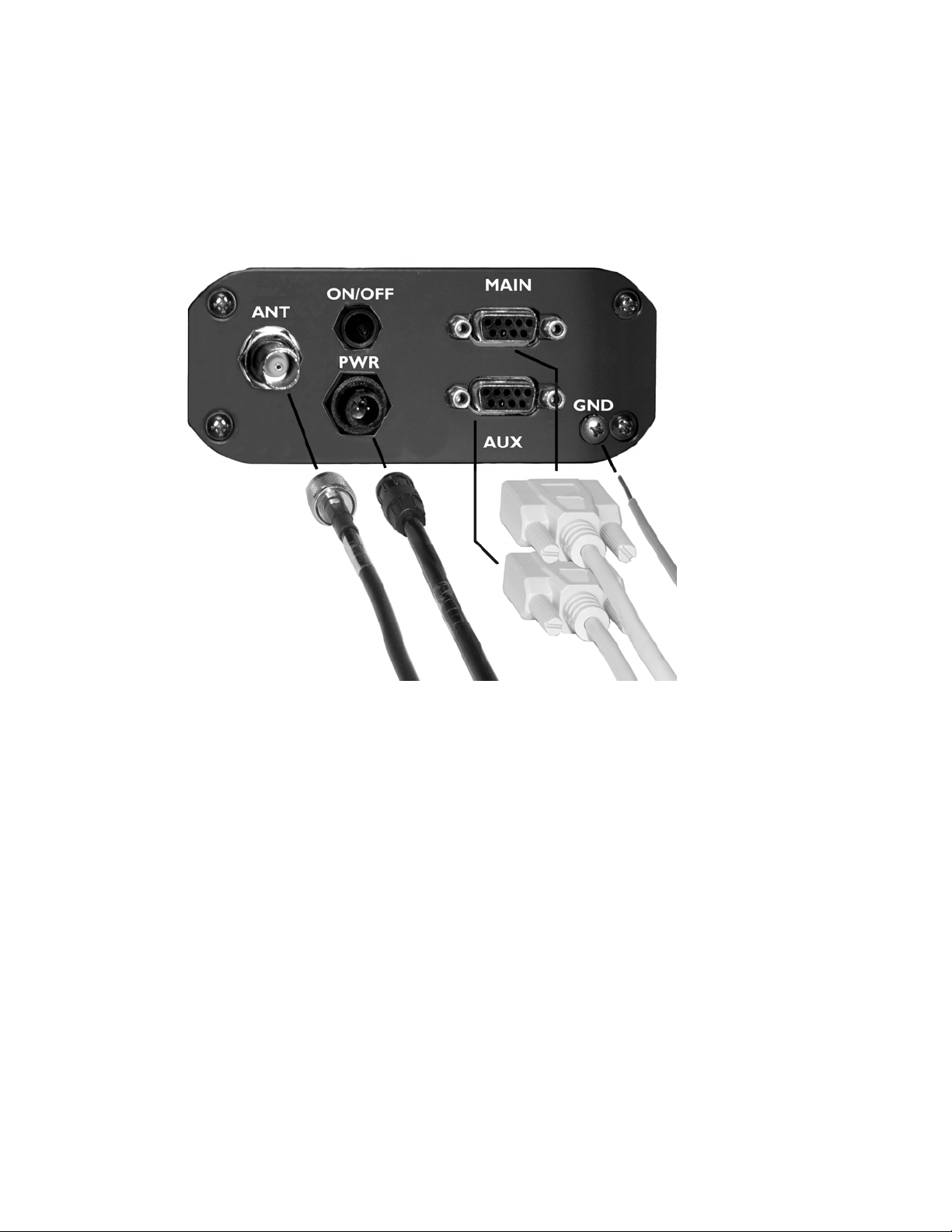
1.2 Receiver Layout and Connections
The RX 400p receiver is easily installed requiring only power, data, antenna, and
ground connections. Figure 2-1 illustrates the cable connections required for the RX
400p receiver.
Caution - The RX 400p receiver provides 5 VDC across the antenna port.
Connection to incompatible devices may result in damage to equipment.
1-1 98-05044
R1
Page 22
RX 400p
Figure 1-1 Cable Interface
1.3 Installing the RX 400p Receiver
To ensure optimum receiver performance and ease of operation, follow the guidelines
presented in the following sections.
1.3.1 Receiver Placement
The flange mounting bracket supplied with the RX 400p is used to secure the
receiver to the selected mounting surface. You may install this bracket on the top or
98-05044 1-2
R1
Page 23

RX 400p
the bottom of the RX 400p. Use the mounting brackets as a template when planning
and drilling mounting holes.
When selecting a location to install the receiver, you should ensure that:
The receiver is within reach of power, data, and antenna cable connections.
Sufficient room is available at the back of the receiver to connect and disconnect the
power, data, antenna, and ground cables.
Once you have installed the receiver, cables will not be bent excessively or pinched.
You have a clear view and access to the receiver’s front panel, to monitor the
receiver status.
1.3.2 Environmental Considerations
The RX 400p is designed to operate in an enclosed environment in which the
temperature remains between -32 °C and +74 °C and relative humidity is less than
95% (non-condensing). The receiver may be stored between -40 °C and +85 °C.
The CDA-2B Antenna is designed to operate in an open environment in which the
temperature remains between -40 °C and +85 °C and relative humidity is as high as
100%. The antenna may be stored at temperatures between -40 °C and +85 °C.
1.3.3 Power Considerations
The RX 400p uses a 2-conductor, positive locking, circular connector for application
of power. The RX 400p accepts an input voltage between 9.2 and 48 VDC. For best
performance, the supplied power should be continuous and clean. Table 1-1 details
the power specifications of the RX 400p receiver.
The back-lit LCD display of the RX 400p remains illuminated while power is applied
to the receiver.
Table 1-1 Power Requirements
Model Input Voltage Input Current
RX 400p (with CDA-2B) 9 to 48 VDC <550 mA @ 12 VDC <6.5 W Nominal
1-3 98-05044
R1
Input Power
Page 24

RX 400p
1.3.4 Turning the RX 400p On
When connected to a suitable power source, the RX 400p may be turned on and off
using the On/Off switch located on the rear panel.
To turn the RX 400p on:
Connect the red wire of the supplied power cable to DC positive (+).
Connect the black wire of the supplied power cable to DC negative (-).
Connect the keyed, two-conductor socket connector of the power cable to the RX
400p.
Turn the RX 400p on, by pressing the ON/OFF switch located on the rear panel
You may press the On/Off switch one more time to turn the receiver off. This will
save you from having to disconnect the power cable from the receiver.
The RX 400p receiver incorporates reverse polarity protection to prevent damage if
the power leads are accidentally reversed.
A 1.5 A slow-blow fuse (or 2.5 A standard blow), situated in-line of the power cable
protects the RX 400p receiver from power surges. The fuse container should remain
accessible after installation.
Caution - Do not operate the RX 400p with the fuse bypassed. Such a
modification will void the product warranty.
1.3.5 Grounding the RX 400p
For best performance, connect the ground screw, labeled ‘GND’, on the back of the
RX 400p to a counterpoise ground (artificial ground). This ground point in most
instances will be the chassis of a vehicle. Other grounds may provide acceptable
performance. You should minimize the overall length of the ground wire for best
performance.
1.3.6 Connecting the RX 400p To External Devices
The RX 400p operates at the RS-232C interface level to communicate with external
data loggers, navigation systems, and other devices. It features two data connectors
98-05044 1-4
R1
Page 25

RX 400p
on the rear panel, labeled ‘MAIN’ and ‘AUX’ to transmit and receive data (refer to
Appendix B Interface Information).
MAIN is the primary interface port for differentially corrected GPS data. The AUX
port is a secondary port designed for input of external RTCM correction data. In the
case that an external differential source is required, you may configure the RX 400p
using the menu system to accept the external correction data through the AUX port.
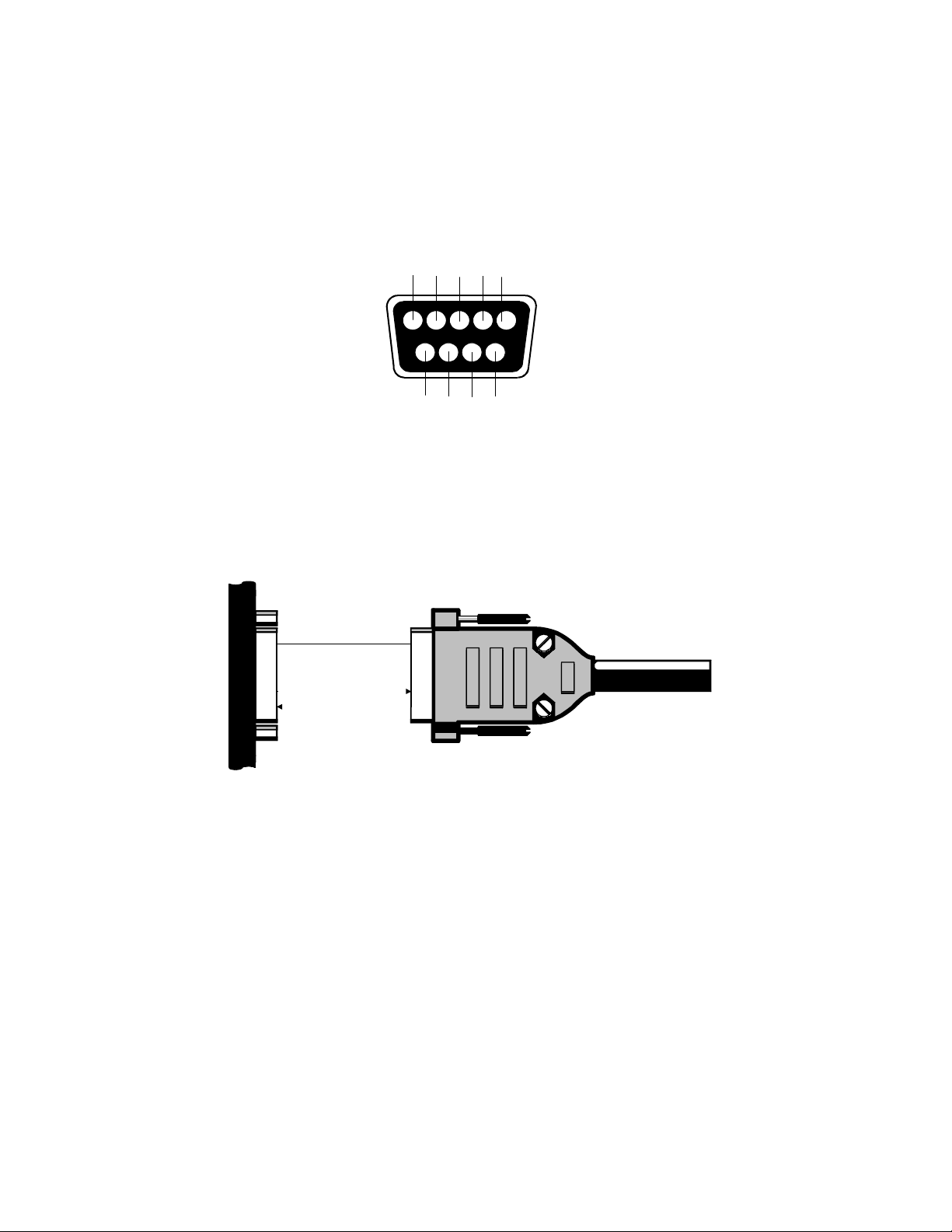
Both data ports are located at the back panel of the RX 400p and are a DB9 socket
connector. Table 1-2 and Table 1-3 provide pin-assignment information for the RX
400p MAIN and AUX serial ports respectively.
Table 1-2 MAIN Pin-out, RS-232C Interface Level
Pin # Signal Description
2 TXD RX 400p NMEA 0183 and binary output
3 RXD RX 400p NMEA 0183 and binary input
5 Sig. Ground Signal return
9 1 PPS 1 Pulse per second timing output (HCMOS, rising edge
synch, 10 kΩ, 10 pF load)
Table 1-3 AUX Port Pin-out, RS-232C Interface Level
Pin # Signal Description
3 RXD RTCM Input (Extrnl RTCM mode only)
5 Sig. Ground Signal Return
6 Event Marker
9 1 PPS
Figure 1-2 displays the numbering scheme for a DB9 socket connector (female), as
located on the rear panel of the RX 400p receiver. The associated numbering for the
plug connector (male) is a mirror reflection of scheme showed in this figure.
1-5 98-05044
R1
HCMOS, active low, falling edge sync, 10 kΩ, 10 pF load
1 Pulse per second timing output (HCMOS, rising edge synch, 10 kΩ, 10 pF
load)
Page 26
RX 400p
1
3
7
2
6
4
958
Figure 1-2 RX 400p Socket Connector Pin Numbering
Figure 1-3 illustrates the standard interface for the RX 400p when interfaced to an
external device:
MAIN
External Device
5 GND GND
NMEA/Binary
3 RX
NMEA/Binary
2 TX
Refer to Appendix B for further interface information when operating in the RX 400p
with various correction sources.
For successful communications, the baud rate of the RX 400p serial ports must be set
to match that of the devices to which they are connected. Refer to Section 4.15.3 and
Section 4.16.3 for instructions related to setting the RX 400p baud rates.
98-05044 1-6
R1
TX
RX
Figure 1-3 RX 400p Interface
Page 27

RX 400p
1.4 Installing the CDA-2B Antenna
The location chosen for installation of the CDA-2B antenna will influence the overall
performance of the RX 400p receiver. When installing the antenna:
Choose a location with a clear, unobstructed view of the sky. This is important for
GPS, WAAS, and OmniSTAR signal reception.
Choose a location that is at least three feet away from all forms of transmitting
antennas, communications, and electronic equipment. This will reduce the amount
of noise present at the antenna, improving beacon receiver performance.
The position calculated by the RX 400p is measured to the center of the CDA-2B
antenna. Install the antenna in the best location for your application, such as the
centerline of your vehicle or vessel.
Do not locate the antenna where environmental conditions exceed those specified in
Section 1.3.2.
1.4.1 Antenna Placement To Optimize Beacon Reception
When using the internal beacon receiver as the correction source, selecting an
appropriate location for installation of the antenna will influence the performance of
the internal beacon receiver of the RX 400p. The following list provides some
general guidelines for deciding upon an antenna location:
Ensure that the antenna is as far as possible from all other equipment that emits
Electromagnetic Interference (EMI), including DC motors, alternators, solenoids,
radios, power cables, display units, and other electronic devices.
If you are installing the antenna on a vessel (using DGPS beacon corrections), mount
the antenna as high as possible, considering maintenance and accessibility. In
addition, ensure that the antenna is lower than the highest metal object on the vessel.
If a radar system is present, mount the antenna outside the path of the radar beam.
Your beacon receiver calculates a Signal to Noise Ratio (SNR), measured in dB
(Decibels) that indicates the receiver’s performance. The SNR is height of the signal
above the noise floor. The higher the SNR, the better your beacon receiver is
demodulating the signal. The optimum antenna location will be a position where
your average SNR is highest. You should turn on all accessories that you intend to
use during normal operation when locating the best position for the antenna.
1-7 98-05044
R1
Page 28

RX 400p
1.4.2 Antenna Installation – 1-14-UNS Threaded Mount
The CDA-2B uses a 1-14-UNS-2B thread for mounting, which is not compatible with
¾ NPT or pipe threads. A magnetic mount accompanies the standard RX 400p
system. An adapter to convert the 1-14-UNS thread to a 5/8
th
inch survey-style
thread is available from MID-TECH, discussed in Section 1.5.3.
Thread the CDA-2B Antenna onto the mount, tightening by hand only. Do not use
any tools for tightening, and do not over-tighten.
Caution - A ¾ NPT or pipe thread is not compatible with the thread of the CDA2B. Use only a 1-14-UNS threaded mount to prevent damage to the antenna
enclosure. This type of damage is not covered under warranty.
Caution - Install the antenna only hand-tight. Damage resulting from overtightening the antenna is not covered by warranty.
1.4.3 Antenna Installation – Surface Mount
The CDA-2B antenna comes with a PVC base pre-installed for mounting on a 1-14UNS threaded mount installed. This base may be removed for surface mounting the
CDA-2B, if desired.
To mount the CDA-2B in this fashion, you must use four 4-40 screws in order to
secure the antenna to the mounting surface. Their length will be dependant upon the
thickness of the mounting surface used. To determine the location of the screw
holes, use the PVC base as a template.
98-05044 1-8
R1
Page 29

RX 400p
Note - The screw holes are not symmetric so that the PVC base cannot be
improperly installed on the antenna. As such, you will have to place the base on
the bottom face of the mounting surface when marking the screw holes, before
drilling. Do not place the base upside down on the top face of the mounting
surface, as the resulting screw holes will not line up correctly.
1.4.4 Routing and Securing the Antenna Cable
The CDA-2B requires a 50 Ω impedance antenna extension cable such as RG-58U
(up to a maximum of 10 m (33 ft) in length) for proper operation. For more
information on cable length or low-loss cable, please contact your MID-TECH dealer
or MID-TECH Customer Service.
When choosing a route for the antenna extension cable:
Avoid running cables in areas of excessive heat.
Keep antenna cables away from corrosive chemicals.
Do not run the extension cable through door or window jams.
Keep the antenna cable away from rotating machinery.
Do not bend excessively or crimp the antenna extension cable.
Avoid placing tension on the cable.
Remove unwanted slack from the antenna extension cable at the receiver end.
Secure along the cable route using plastic tie wraps.
Caution - The RX 400p receiver provides 5 VDC across the antenna port.
Connection to incompatible devices may result in damage to equipment.
Warning - Improperly installed cables near machinery can be dangerous
1.4.5 Connecting the CDA-2B Antenna
The CDA-2B Antenna connects to the RX 400p receiver using the supplied TNCmale to TNC-male antenna cable. To connect the CDA-2B Antenna to the RX 400p:
Thread one end of the TNC to TNC antenna extension cable onto the TNC socket
present on the CDA-2B
1-9 98-05044
R1
Page 30

RX 400p
Thread the other end of the antenna extension cable to the TNC socket connector on
the rear panel of the RX 400p, labeled CDA-2B.
Caution - Be sure to always connect the antenna to the RX 400p before you turn
the receiver on.
98-05044 1-10
R1
Page 31

RX 400p
1.5 Mounting Accessories
MID-TECH offers various mounting accessories as discussed in the following
sections.
1.5.1 Magnetic Mount
Included with a standard system, the magnetic mount (PN 725-0007-012) can be used
to install the CDA-2B antenna on any ferrous surface including the roof of a vehicle.
It consists of a mounting extension two inches long, attached to a circular metal disk,
housing a magnet. A protective membrane covers the bottom of the mount protects
the mounting surface from abrasion.
A three inch diameter zinc plated steel disc and a double sided adhesive foam pad are
included with the magnetic mount to attach the magnetic mount to non-ferrous
surfaces, such as fiberglass rooftops. For such an installation, remove the protective
backing from both sides of the adhesive foam pad, and affix the foam pad to the nonferrous surface. Place the disc on top of the foam pad. You can then place the
magnetic mount securely on the metal plate, and remove as necessary.
The threaded shaft of the mount may be removed from the magnetic disk and used as
a threaded insert for survey applications that use the common 5/8
MID-TECH part number for the threaded shaft is 78-50069.
th
-inch thread. The
1.5.2 Survey Adapter
The optional Survey Adapter is a threaded insert available for use with the CDA-2B
antenna. It converts the standard 1-14-UNS-2B thread to a 5/8
frequently used with survey equipment (MID-TECH PN 78-50069). This survey
adapter is the same part as used for the shaft of the magnetic mount
1-11 98-05044
R1
th
-inch thread,
Page 32

Page 33

RX 400p
2 RX 400p Overview
For your convenience, all internal sensors within the RX 400p feature automatic
tuning algorithms, which are in operation by default.
When powered for the first time, the RX 400p receiver will perform a ‘cold start’,
which involves acquiring the available GPS satellites in view and the WAAS
differential service.
If WAAS is not available in your area, either of the other two internal differential
sensors, the beacon or L-band receiver, may be used. The beacon receiver will scan
the beacon spectrum for the best signal, and maintain an acquisition on the best
station at all times. Should a superior station become available as you navigate with
your positioning system, the beacon sensor will automatically acquire that station.
This chapter describes the various modes of operation and features of your RX 400p
receiver and its internal sensors.
2.1 GPS Operation
The GPS engine is always operating, regardless of the DGPS mode of operation. The
following sections describe the general operation of the RX 400p’s internal GPS
engine.
2.1.1 Automatic Tracking
The GPS engine within the RX 400p automatically searches for GPS satellites,
acquires the signal, and manages the associated navigation information required
positioning and tracking. This is a hands-free mode of operation.
2.1.2 Receiver Performance
There are two main aspects of GPS receiver performance - positioning accuracy and
satellite acquisition quality.
2-1 98-05044
R1
Page 34

RX 400p
The estimated positioning precision is accessible through the menu system of the RX
400p receiver. Although this feature is intended for advanced users, it will provide
the real-time estimates of precision. As the receiver is not able to determine accuracy
with respect to a known location in real time (this is traditionally performed in postmission analyses), the precision numbers are relative in nature. More about this
feature is discussed in Section 4.9.1.1.
Satellite acquisition quality is described as a signal to noise ratio (SNR). A higher
SNR is indicative of better quality signal reception. SNR information is provided by
the RX 400p via its menu system on a per channel basis numerically as well as
presenting this information symbolically in a bar chart. More about this feature is
discussed in Sections 4.7 and 4.9.2.
2.2 WAAS Operation
The following sections describe the general operation and performance monitoring of
the WAAS demodulator within the RX 400p.
2.2.1 Automatic Tracking
The WAAS demodulator featured within the RX 400p will automatically scan and
track the WAAS satellite signals. This automatic tracking allows you to focus on
other aspects of receiver operation without the need to tune the receiver.
The WAAS demodulator features two-channel tracking that provides an enhanced
ability to maintain acquisition on a WAAS satellite in regions where more than one
satellite is in view. This redundant tracking approach will result in more consistent
acquisition of a signal when in an area where signal blockage of either satellite is
possible.
2.2.2 Receiver Performance
The performance of the WAAS receiver is described in terms of lock icon and a bit
error rate (BER). WAAS requires a line of sight to the WAAS satellites in order to
acquire the signal.
98-05044 2-2
R1
Page 35

RX 400p
The BER number indicates the number of unsuccessfully decoded symbols in a
moving window of 2048 symbols. Due to the use of forward error correction
algorithms, one symbol is composed of two bits.
A lower BER indicates that data is being successfully decoded with fewer errors,
providing more consistent throughput. The BER numbers for both satellites, if
available in your region, are presented in the menu system of the RX 400p. The bit
error rate has a default, no-lock value of 500 or more. As the receiver begins to
successfully acquire the signal, it will result in a lower bit error rate. For best
operation, this value should be less than 150 and ideally less than 20.
Section 4.10.1 provides more information on the display of the BER. A graphical
presentation of the reception quality is provided in the signal tracking bar chart. Refer
to Section 4.7 for further information.
2.3 OmniSTAR Operation
The following sections describe the general operation and performance monitoring of
the OmniSTAR sensor within the RX 400p.
2.3.1 Automatic Tracking
The RX 400p features an Automatic mode that allows the receiver to locate the best
L-band spot beam if more than one is available in a particular region. This function
frees you from having to adjust the frequency of the L-band DGPS receiver. For
flexibility, the OmniSTAR receiver also features a manual tune mode.
2.3.2 Receiver Performance
The internal OmniSTAR receiver provides both a lock icon and a bit error rate to
describe the lock status and reception quality. Both of these features depend on a
line-of-sight between the CDA-2B antenna and the geostationary communications
satellite broadcasting OmniSTAR correction information.
2-3 98-05044
R1
Page 36

RX 400p
The CDA-2B Antenna is designed with sufficient gain at low elevation angles to
perform well at higher latitudes where the signal power is lower and the satellite
appears lower on the horizon.
The BER number indicates the number of unsuccessfully decoded symbols in a
moving window of 2048 symbols. Due to the use of forward error correction
algorithms, one symbol is composed of two bits.
The bit error rate has a default, no-lock value of 500. As the receiver begins to
successfully acquire the signal, it will result in a lower bit error rate. For best
operation, this value should be less than 150 and ideally less than 20.
Section 4.11.1 provides more information on this feature. A graphical presentation of
the reception quality is provided in the signal tracking bar chart. Refer to Section 4.7
for further information.
2.4 Beacon Operation
The following sections describe the general operation and performance monitoring of
the beacon engine within the RX 400p.
2.4.1 Tune Modes
The RX 400p may be operated in either Automatic or Manual Beacon tune modes.
In Automatic Beacon Search (ABS) mode, the receiver will identify and tune to the
station providing the strongest DGPS signal. In Manual Tune mode, you specify the
frequency to which the receiver will tune, or select the desired beacon by name from
the built-in global listing.
Refer to Figure 5-12 and Section 4.16.5.3 to switch between Automatic and Manual
Tune modes using the display and keypad.
2.4.1.1 Automatic Beacon Search (ABS) Mode
When operating using the internal beacon sensor as the source of DGPS correction
information, the RX 400p operates in Automatic Beacon Search (ABS) mode by
98-05044 2-4
R1
Page 37

RX 400p
default, selecting and tuning to the most appropriate beacon without operator
intervention. The RX 400p’s internal beacon receiver uses its two independent
beacon channels to identify and lock to DGPS beacons without interrupting the
continuous flow of RTCM data to the GPS receiver.
ABS mode is ideal for navigation applications over considerable areas, eliminating
the need for operator intervention when transitioning from one beacon coverage zone
to another.
When desired, you may also tune the beacon receiver manually by using the menu
system. This is discussed in Section 4.12.2.
2.4.1.2 ABS Global Beacon Search
When powered for the first time in ABS mode, the RX 400p initiates a Global Search
using, examining each available DGPS beacon frequency, and recording Signal
Strength (SS) measurements in units of dBµV/m to the Global Search Table. The
receiver uses these measured values to compute an average SS, and noise floor, to
sort the frequencies in descending order of SS. The beacon receiver’s two channels
cooperatively examine the frequencies with the highest SS measurements, above the
computed noise floor, to determine the station providing the strongest RTCM signal.
The receiver's primary channel locks to the first identified DGPS broadcast, while the
second channel continues searching in the background for superior beacon signals. If
no signal is available, the RX 400p will initiate a fresh Global Search, continuing this
cycle until it finds a valid station.
2.4.1.3 ABS Background Beacon Search
During the Background Search, the second beacon channel examines all frequencies
at both 100 and 200 bps MSK bit rates to identify beacons possessing superior signal
quality. If a DGPS broadcast is identified that exhibits a 2 dB greater signal strength
than that of the primary station, the receiver will automatically switch to this beacon.
No loss of lock occurs on the primary station during the background scan.
2-5 98-05044
R1
Page 38

RX 400p
The RX 400p stores the current primary beacon in memory so that it is available
upon subsequent power-up. You may force a new Global Search at any time using
the display and keypad by selecting the Auto Tune@ menu item as discussed in
Section 4.12.2.
2.4.1.4 Manual Tracking
In Manual tune mode, you may select a specific frequency and bit rate for the
receiver to tune, or specify the frequency only, allowing the RX 400p to identify the
correct MSK bit rate on its own. This mode of operation is most useful when
working in an area where you know the frequency though not necessarily the MSK
bit rate of the closest beacon.
The RX 400p also provides the capability to select a beacon by name from the World
Beacon Table stored within receiver memory. This feature is discussed in more
detail in Section 4.12.2 and 4.12.2.1.
2.4.2 Receiver Performance
The Signal to Noise Ratio (SNR) best describes the internal SBX-2 beacon receiver
performance. The SNR, measured in dB, is the height of the signal above the noise
floor. The higher the SNR, the more successfully the beacon receiver is
demodulating the signal. You can easily monitor the SNR in the Beacon Status
menu.
Table 2-1 describes the beacon receiver quality of reception with respect to the SNR
reading.
98-05044 2-6
R1
Page 39

RX 400p
Table 2-1 Beacon Receiver Performance - SNR Reading
SNR Reception Description Approximate Data Throughput
>25 Excellent 100% data throughput
20 to 25 Very Good 100% data throughput
15 to 20 Good Good data throughput up to 100%
10 to 15 Stable Moderate to good data throughput
7 to 10 Intermittent Low data throughput
<7 No Lock No data throughput
A graphical presentation of the reception quality is provided in the signal tracking bar
chart. Refer to Section 4.7 for further information.
2.5 Factory Default Parameters
Tables 2-2, 2-3, and 2-4 identify the default RX 400p configuration settings of the
various RX 400p Series receivers.
Caution - The changes you make to the RX 400p configuration are saved in
memory for subsequent power-up.
2-7 98-05044
R1
Page 40

RX 400p
Table 2-2 Preset DGPS Mode
DGPS Mode
WAAS
Table 2-3 Preset Port Settings
Serial Port Baud Rate Data Bits Parity Stop Bit Interface Level
MAIN 9600 8 None 1 RS-232C
AUX 9600 8 None 1 RS-232C
Table 2-4 Preset GPS NMEA Message Output
GPS NMEA Messages Update Rate Max DGPS Age Elevation Mask
GGA, GSV, VTG, ZDA 1 Hz 1800 seconds
5°
98-05044 2-8
R1
Page 41

RX 400p
3 RX 400p Architecture
The RX 400p receiver is comprised of two main components – hardware and
software. This chapter provides an overview of the hardware and software
architecture of the RX 400p receiver in order to provide further insight into the
operation of the product.
As the RX 400p receiver supports the following services, it requires receiving
capability for each:
GPS
WAAS
OmniSTAR
Beacon
3.1 Hardware
The SLX receiver inside the RX 400p drives the menu system and provides receiving
capability for GPS, WAAS, and OmniSTAR. This platform comprises the main
portion of the RX 400p receiver.
The SLX is designed to process GPS and L-band signals simultaneous, using specific
hardware and software. A built-in WAAS demodulator uses the same hardware as
the GPS receiver, as it does not require its own specific circuitry.
Onboard the SLX is an SBX beacon receiver engine that demodulates beacon signals
and communicates them to the SLX GPS through an internal serial port.
3.2 Firmware
3-1 98-05044
R1
Page 42

RX 400p
As the software that operates the internal components of the RX 400p operates at a
low level, it is often referred to as firmware.
There are three types of firmware within the SLX - DSP, ARM, and menu system
firmware. Each of these types of firmware may be upgraded in the field through the
MAIN serial port, as new revisions become available.
The SBX beacon receiver that resides on-board the SLX incorporates its own version
of firmware. The firmware of the SBX may also be upgraded through the MAIN
serial port.
3.3 Applications
The ARM of the SLX inside the RX 400p supports two simultaneous versions of
firmware. Only one of them is in operation at a given time. These two versions of
firmware may have different functionality, and are also referred to as applications.
The RX 400p ships with two resident applications - WAAS and OmniSTAR.
Switching between the WAAS and OmniSTAR DGPS mode effectively changes the
current application. The receiver is automatically rebooted during this operation. No
operator intervention is required.
98-05044 3-2
R1
Page 43

RX 400p
4 Operation
This chapter introduces the display and keypad features of the RX 400p, operating
modes, menu structure, and receiver default operating parameters.
4.1 Front Display and Keypad
The RX 400p features a 2-line by 16-character LCD and 3-button keypad. The
keypad is composed of an up arrow
1 shows the display and keypad of the RX 400p receiver.
, enter , and down arrow key. Figure 4-
Figure 4-1 RX 400p Display and Keypad
4-1 98-05044
R1
Page 44

RX 400p
4.2 Navigating the Menu System
The keypad on the front of the RX 400p allows you to navigate through the intuitive
menu system, configuring operating parameters and viewing status information. The
top line of the display is the active Focus Line for keypad operations. Menu items
that are being accessed must be on the top line of the display for the desired effect to
occur.
Note - The top line of the RX 400p display is the Focus Line. The field of
interest must be ‘in focus’ for keystrokes to have the desired effect.
4.3 Menu Access Icon
The icon shown in Figure 4-2 indicates that you may access the current item in focus
by pressing the
key.
@
Figure 4-2 Menu Access Icon
4.4 Receiver Status Icons
The following sections describe the status icons of the RX 400p receiver. The icons
displayed by the RX 400p depend on the current operating mode of the receiver and
its current lock status.
98-05044 4-2
R1
Page 45

RX 400p
4.4.1 Position Fix Status Icon
The RX 400p provides an indication of the GPS lock status, as contained within the
GPGGA data message string output from the data port of the receiver. This
indicator is located in the lower right hand corner of the RX 400p display. Figure 43, illustrates the three states of the GPS status icon.
% & ^
No GPS Fix GPS Position DGPS Position
Figure 4-3 GPS Position Fix Icon
In the first state, the two parallel vertical lines indicate that no position fix is
available. The second state, denoted by the hollow circle between the two parallel
vertical lines, indicates that the receiver is tracking four satellites or more, and is
computing an uncorrected position. This indicator is a symbol representing a GPS
satellite. The third state, denoted by the solid circle between the two parallel vertical
lines, indicates that the GPS receiver is computing differentially corrected position
solutions.
4.4.2 WAAS Lock Icon
When the RX 400p is configured to use WAAS correction information, The RX 400p
receiver will display the lock status on at the far right of the top line of the display.
The lock symbol illustrated in the following figure remains in the ‘No WAAS Lock’
position until the receiver has acquired the signal, at which point the receiver will
display the ‘WAAS Lock’ icon.
4-3 98-05044
R1
Page 46

RX 400p
a A
No WAAS Lock WAAS Lock
Figure 4-4 WAAS Lock Icon
4.4.3 OmniSTAR Lock Icon
When operating using the internal L-band receiver as the differential source, the RX
400p receiver indicates the OmniSTAR DGPS lock status in the upper right corner of
the display. The lock symbol, illustrated in Figure 4-5, remains in the ‘No L-band’
DGPS Lock state until the receiver has acquired the DGPS satellite transmission at
which point the symbol changes to the ‘L-band Lock’ icon. The L-band DGPS
receiver will lock to the satellite signal although a valid subscription is not present
within the receiver in order to provide the facility to subscribe the receiver over the
air.
* +
No L-band Lock L-band Lock
Figure 4-5 L-band Lock Icon
Note - When using corrections from the OmniSTAR service, the GPS output of
the RX 400p will not be differentially corrected until lock has been attained on
an OmniSTAR broadcast with a subscribed receiver.
98-05044 4-4
R1
Page 47

RX 400p
4.4.4 Beacon Lock Icon
When using the internal beacon sensor as the differential source, the RX 400p
indicates beacon lock status in the upper right hand corner of the display. The lock
symbol, illustrated in Figure 4-6, remains in the closed position when the RX 400p is
locked to a valid beacon signal, and open, when no broadcast is available for the
specified frequency and/or MSK bit rate.
# $
No Beacon Lock Beacon Lock
Figure 4-6 Beacon Lock Icon
Note – When using beacon corrections, the GPS output of the RX 400p will not
be differentially corrected until the beacon receiver locks to a valid RTCM
broadcast.
4.4.5 External DGPS Correction Source Icon
The icon shown in Figure 4-7 indicates that the RX 400p receiver is currently
operating with corrections input from an external source. This icon symbolizes
external correction input to a DB9 connector.
?
Figure 4-7 External DGPS Source Icon
4-5 98-05044
R1
Page 48

RX 400p
4.4.6 Autonomous Mode Icon
The Icon shown in the following figure indicates that the receiver is configured to
position autonomously, with no DGPS correction source.
@
Figure 4-8 Autonomous Mode Icon
4.5 RX 400p Menu System Overview
This section shows you how to navigate through the menu system of the RX 400p
receiver, change operating modes, monitor position and status information, and
change receiver configuration. Figures 4-9 to 4-15 illustrate the various menus in the
menu system.
The root, or main menu, contains main parent menus - a GPS menu, a differential
menu, a Configuration Wizard menu, and a System Setup menu.
The GPS, Configuration Wizard, and System Setup menus remain the same
regardless of the operating settings of the RX 400p receiver. However, the name and
content of the differential menu depends on the differential correction source
currently in use. Available DGPS operating modes include WAAS, OmniSTAR,
Beacon, Autonomous, and External RTCM Input mode.
In Figures 4-9 to 4-15, the root menu is displayed on the left, with associated
submenus displayed progressively towards the right. Each of the figures is described
in the following sections in detail.
98-05044 4-6
R1
Page 49

RX 400p
^
^
^
^
^
^
GPS@???????????
WAAS@ ? ^
Config Wizard@
System Setup@
Res rms: 0.3m?
=_a:??????0.2m?^
=_b:??????0.1m
Azimuth:163.1!
=_Lat:????0.2m?
=_Lon:????0.2m
A
`??51!00.131035
~_114!00.273158
Hgt?1030.40m
Hdg 187.3!t
Vel 10.5?kph
Time?11:32:45.2
Age?? 5.6?s
SV Count 07
HDOP 1.3
Precision@
ENTER
NavCnd@ ABBABB
DSP_ARM@1F_1F
Back@
Top Menu@
CH01_SV23?EL?37
AZ??092?SNR??45
???????.
???????.
???????.
CH12_SV09?EL?45
AZ??183?SNR??47
Back@
Data Output@???
Elev Mask@?? 5!^
MaxDGPSAge@1800
UTC Offset@ _7h
Back@
Top?Menu@
ENTER
ENTER
A
PositionStatus@
Satellites@????
Configure@
Back@
Top Menu@
A
ENTER
ENTER
A
A
A
ENTER
=_Alt:????0.3m
Back@
Top Menu@
Car Smooth??11?
Eph Exists??11?^
ENTER
Eph Healthy?10
NotUsed?Prev11
Above Ele 11
Diff Corr 10
No Diff Corr 0
Back@
Top Menu@
ENTER
DSP:CarLock YES
DSP:BER YES
DSP:DSPLock YES
DSP:FrmSync YES
DSP:TrkMode YES
ARM:GPSLock YES
ARM:DifData YES
ARM:ARMLock YES
ARM:DGPS YES
ENTER
ARM:Solutn YES
Back@
Top Menu@
1233213331 A41
^?
4444444444 44
GGA @?5?Hz
GGA @?1?Hz ^
GLL @?Off
GSA @?Off
GST @?Off
GSV @?1?Hz
RMC @?1?Hz
RRE @ Off
VTG @?5?Hz
ZDA @?Off
Bin95@?Off
Bin96@ Off
RTCM @?On
Back@
Top?Menu@
A
A
A
A
Figure 4-9 GPS Menu
ENTER
A
<
GPS@???????????
WAAS@ ? ^
Config Wizard@
System Setup@
BER?122:?? 0?
BER?134:?? 0?^
LN? 122: _54.0!
LN? 134: 178.0!
Elev122:? 9.8!
ENTER
Elev134:? 5.0!
Az? 122: 114.0!
Az? 134: 252.6!
ENTER
Back@
Top?Menu@
Diff@WAAS
A
ENTER
Signal Status@
Configure@ ^
Back@
Top Menu@
A
4-7 98-05044
R1
?
Page 50

RX 400p
+
^
+
^
GPS@???????????
OmniSTAR@ ? ^
Config Wizard@
System Setup@
Figure 4-10 WAAS Menu
123321333123 32
^+
444444444444 44
ENTER
Subscription OK
Region?????? OK
Sat?Link?????OK
ENTER
ENTER
ENTER
Maritime?????OK
Remote?Site??OK
Almanac??????OK
Position?????OK
Time?????????OK
Sat?Update???OK
Back@
Top?Menu@
Diff@OmniSTAR
Begin Date@ +
Expiry?Date@???^
SerialNum?Disp@
Countdown?Tmr@
Back@
Top?Menu@
<
F 1551489/1200 +
BER?001 AA ^
Difstatus@
LN?? _101.0!
Elevation?31.6!
ENTER
Azimuth??163.4!
Back@
ENTER
Top?Menu@
Diff@OmniSTAR ?
F@1551489/1200
AutoTune@
Subscription@??
Back@
Top?Menu@
+
ENTER
Signal Status@ +
Configure@ ^
Back@
Top Menu@
Figure 4-11 OmniSTAR Menu
98-05044 4-8
R1
Page 51

RX 400p
444444444444
^$
123321333124 32
GPS@???????????$
Beacon@ ? ^
Config Wizard@
System Setup@
ENTER
Signal Status@ $
Configure@ ^
Back@
Top Menu@
ENTER
ENTER
F? Auto/Auto AA$
SS 54?SNR?26? ^
MTP?100>?Q?25?
Unselected?Bx
ID?0001??H?01
Back@
Top?Menu@
Diff@Beacon? $
Tune@Auto?Auto?^
Auto Tune@
TuneBeaconName@
Table Version@
Back@
Top?Menu@
ENTER
ENTER
ENTER
ENTER
ENTER
ENTER
444444444444 44
Diff@Beacon
Tune@ Auto Auto
Beacon Receiver
Auto Scanning
Africa
Asia
Australia
Central?America
Europe
North?America
South?America
Back@
Bermuda
Canada
U.S.A.
Back@
Alexandria?VA???
?
Annette?Is?AK
???????.
???????.
???????.
Youngstown?NY
Back@
Beacon Table
Ver: C101_0.000
<
<
ENTER
ENTER
Figure 4-12 Beacon Menu
GPS@???????????
Extern RTCM@ ^
Config Wizard@
System Setup@
4-9 98-05044
R1
^?
12332133312
ENTER
?
ENTER
External RTCM
Diff@Extrn RTCM^
RTCM In@ 9600
Back@
Top Menu@
?
ENTER
Diff@Extrn RTCM
ENTER
Match External
Baud rt. to RTCM
RTCM In@ 9600
?
<
ENTER
<
Figure 4-13 External RTCM Input Menu
Page 52

^
RX 400p
GPS@???????????
Autonomous@ ^
Config Wizard@
System Setup@
@
ENTER
No Diff Source
Diff@Autonomous^
Back@
Top Menu@
Figure 4-14 Autonomous Menu
ENTER
@
In Use: WAAS
Other : OmniSTAR
12332133312 @
444444444444
?
GPS@???????????
WAAS@ ? ^
Config Wizard@
System Setup@
A
ENTER
Display Apps@
Display Format@^
Baud Rates@
Software Disp@
Back@
Top Menu@
Figure 4-15 Setup Menu
98-05044 4-10
R1
ENTER
ENTER
A
ENTER
ENTER
DispUpdate@5 Hz
LL Unit@DM.M
Hgt Unit@meters
Vel Unit@km/h
Back@
Top Menu@
NMEA I/O@ 9600?
RTCM In @ 9600 ^
Back@
Top Menu@
Menu System@
SLX DSP@ ^
SLX ARM@
SBX@
Back@
Top Menu@
A
A
A
Page 53

RX 400p
4.6 Start-Up Sequence
When you turn the RX 400p on, it will sequence through a startup screen followed by
a prompt asking if you’d like to use the Configuration Wizard. This prompt has a 3second timeout where the receiver will proceed to the Position Status menu unless the
button is pressed. If is pressed, the menu system will begin the Configuration
Wizard. Consult Chapter 6 for further information on the Configuration Wizard.
4.7 Signal Tracking Bar Chart
When you press the button with a menu item in focus that does not have the menu
access indicator, @, a bar chart is displayed that provides signal tracking information.
1233213331 A41
^
4444444444 44
The bar chart consists of two main parts, provides an indication of the GPS satellite
signal quality per receiver channel and the signal quality of the differential source.
For each bar, the higher the bar, the greater the signal quality.
The first portion of the chart, denoted by the GPS icon, ^, indicates the GPS satellite
receiving quality on a per channel basis. The second portion, denoted by the DGPS
icon (A, $, +, ?, or @) of the current mode of operation, provides the signal tracking
information for that correction source, if appropriate. If the external correction input
or the autonomous mode of differential operation is selected, the receiver will not
display status information for a correction source.
4-11 98-05044
R1
Page 54

RX 400p
4.7.1 WAAS Mode Bar Chart
When operating the RX 400p receiver in WAAS mode, the portion of the bar chart to
the right of the WAAS mode indicator, A, reflects WAAS tracking performance. The
WAAS bar chart will reflect the quality of the bit error rate (BER) for WAAS signal
reception. A higher bar is indicative of a better BER.
A good BER is zero and no lock is 500 or greater. A full height bar (16 pixels tall,
including both the top and bottom rows of the display) represents a BER of zero as
shown below. A BER of 500 or greater will be displayed with minimum bar height,
and will be only 2 pixels tall. Intermediate quality signals are shown with a bar
height relative to the reception quality.
1233213331 A41
^
4444444444
In the case of WAAS, since there are two WAAS satellites available, two BER’s are
provided. The first bar is for WAAS PRN 122 and the second for WAAS PRN 134.
44
4.7.2 OmniSTAR Mode Bar Chart
When operating the RX 400p receiver in OmniSTAR mode, the portion of the bar
chart to the right of the OmniSTAR mode indicator, +, reflects OmniSTAR tracking
performance. The OmniSTAR bar chart will reflect the quality of the bit error rate
(BER) for OmniSTAR signal reception. A higher bar is indicative of a better BER.
A good BER is zero and no lock is 500. A full height bar (16 pixels tall, including
both the top and bottom rows of the display) represents a BER of zero as shown
below. A BER of 500 will be displayed with minimum bar height, and will be only 2
pixels tall. Intermediate quality signals are shown with a bar height relative to the
reception quality.
98-05044 4-12
R1
Page 55

RX 400p
1233213331
^
4444444444 4
+
4
4.7.3 Beacon Mode Bar Chart
When operating the RX 400p receiver in beacon mode, the portion of the bar chart to
the right of the beacon mode indicator, $, reflects tracking performance. The beacon
bar chart will reflect the quality of the signal strength (SS) and the signal to noise
ration (SNR) for beacon signal reception. A higher bar is indicative of better signal
variables.
A full height bar (16 pixels tall, including both the top and bottom rows of the
display) represents an SS of 35 or greater and an SNR of 24 or greater. SS and SNR
values of zero will be displayed with minimum bar height, and will be only 2 pixels
tall. Intermediate quality signals are shown with a bar height relative to the reception
quality.
1233213331 $43
^
4444444444 44
In the case of Beacon, there are two signal figures, the SS and SNR reading. The
first bar indicates the SS value and the second the SNR reading.
4.7.4 External RTCM Input Bar Chart
When operating the RX 400p receiver in External RTCM Input mode, the portion of
the bar chart to the right will display the external RTCM input icon ?. No associated
status data is provided for the external correction source.
4-13 98-05044
R1
Page 56

RX 400p
1233213331 ?
^
4444444444
4.7.5 Autonomous Mode Bar Chart
When operating the RX 400p receiver in autonomous mode, the portion of the bar
chart to the right will display the autonomous icon @. No associated status data is
provided for this mode of operation.
1233213331 @
^
4444444444
4.8 Main Menu
The RX 400p will display the following menu when the boot sequence has been
completed upon startup. This is the top, or Main menu.
GPS@???????????A
WAAS@? ^
Config Wizard@
System Setup@
Pressing the
Pressing the
and keys allows you to scroll through the available menu items.
button with any item in focus (on the top line) will take the menu
system to that submenu.
98-05044 4-14
R1
Page 57

RX 400p
GPS@
WAAS@
Config Wizard@
System Setup@
When this menu is accessed using the button,
the menu system displays the contents of the GPS
menu, providing access to position and satellite
information, and access to GPS setup parameters.
When this menu is accessed using the button,
the RX 400p menu displays the contents of the
DGPS menu.
Depending on the differential mode of operation,
this menu will be named WAAS, OmniSTAR,
Beacon, Extern RTCM, or Autonomous. Inside
this menu will be status-related information and
configuration parameters. The structure of this
menu differs from one DGPS mode to another.
When this menu item is accessed using the
button, the Configuration Wizard will begin. This
feature allows you to easily configure the RX
400p step-by-step. This feature is described in
detail in Chapter 5.
When this menu is accessed, the menu system will
display the contents of the System Setup menu.
Inside this menu, you’ll have the ability to change
baud rates, view the current applications in
memory, customize the display parameters, and
monitor the versions of firmware installed in the
RX 400p receiver.
4.9 GPS Menu
4-15 98-05044
R1
Page 58

RX 400p
The GPS@ menu contains sub-menus that provide access to position and satellite
status information, and GPS receiver configuration parameters. Please note that the
icon in the lower corner of the display will change according to the GPS fix as shown
in Figure 4-3. This portion of the menu system, including submenus, is detailed in
Figure 4-9.
PositionStatus@+
Satellites@????^
Configure@
Back@
Top Menu@
Pressing the
menu items. Pressing the
system to that submenu. Pressing the
and keys in this menu allows you to scroll through the available
button with any item in focus will take the menu
button with the Back@ or Top Menu@
item in focus will take the menu system to the previous menu or the Main menu,
respectively.
PositionStatus@
Accessing this menu item using the button
allows you to monitor position-related
information, such as latitude, longitude, altitude,
and time. Other useful information is also
presented in this menu.
Satellites@
When this menu item is accessed using the
button, the menu system will display the GPS
satellite tracking status on a channel-by-channel
basis.
98-05044 4-16
R1
Page 59

RX 400p
Configure@
Entering this menu using the button will allow
you to change various configuration parameters
related to the GPS receiver inside the RX 400p.
This includes NMEA message output settings,
elevation cut-off mask, differential time-out, and
UTC offset.
Back@
When accessed using the button, this menu
item returns the menu system to the previous
menu.
Top Menu@
When accessed using the button, this menu
item returns the menu system to the main menu.
4.9.1 GPS Position Status Menu
The
PositionStatus@
and navigation status information. This portion of the menu system, including
submenus, is detailed in Figure 4-9.
section of the menu tree provides access to GPS position
4-17 98-05044
R1
Page 60

RX 400p
`??51!00.131035A
~_114!00.273158^
Hgt?1030.40m
Hdg 187.3!t
Vel 10.5?kph
Time?11:32:45.2
Age?? 5.6?s
SV Count 07
HDOP 1.3
Precision@
NavCnd@ ABBABB
DSP_ARM@1B_1F
Back@
Top Menu@
Pressing the
Pressing the
tracking information. Pressing the
and keys allows you to scroll through the available menu items.
button anywhere in this menu will provide a bar chart of signal
button with the Back@ or Top Menu@ item
in focus will take the menu system to the previous menu or the Main menu,
respectively
98-05044 4-18
R1
Page 61

RX 400p
`??51!00.131035
~_114!00.273158^
This menu item displays the current antenna
latitude in degrees / minutes / decimal minutes
(DM.M) by default. Other display formats are
possible, including degrees / decimal degrees
(D.D) and degrees / minutes / seconds (DMS).
These other display formats are discussed in
further detail in Section 4.15.2.
Latitude information is parsed from the GPGGA
NMEA message. The latitude, measured to the
phase center of the antenna, is usually referenced
to the WGS-84 ellipsoid, however, some DGPS
services result in a position relating to the North
American Datum 1983 (NAD-83). This datum is
essentially equivalent to this ellipsoid,
considering the level of accuracy of this product.
This menu item displays the current antenna
longitude in degrees / minutes / decimal minutes
(DM.M) by default. Other display formats are
possible, including degrees / decimal degrees
(D.D) and degrees / minutes / seconds (DMS).
These other display formats are discussed in
further detail in Section 4.15.2.
4-19 98-05044
R1
Page 62

RX 400p
Hgt 1030.40m
Hdg 187.3!t
Vel 10.5 kph
Longitude information is parsed from the
GPGGA NMEA message. The longitude,
measured to the phase center of the antenna, is
usually referenced to the WGS-84 ellipsoid,
however, some DGPS services result in a
position relating to the North American Datum
1983 (NAD-83). This datum is essentially
equivalent to this ellipsoid, considering the level
of accuracy of this product.
This menu item displays the current antenna
height in either meters or feet depending on the
units selected (See Section 4.15.2). The default
unit is meters. This information is parsed from
the NMEA GPGGA message.
The altitude, measured to the phase center of the
antenna, is usually referenced to the WGS-84
ellipsoid, however, some DGPS services result in
a position relating to the North American Datum
1983 (NAD-83). This datum is essentially
equivalent to this ellipsoid, considering the level
of accuracy of this product.
This item displays the horizontal heading
clockwise from True North in degrees. This
information is parsed from the GPVTG NMEA
message string.
This item displays the horizontal speed in KPH
by default. The units may be changed to MPH or
knots if desired (See Section 5.15.2 for details on
configuring the units of this item). This
information is parsed from the GPVTG NMEA
message.
98-05044 4-20
R1
Page 63

RX 400p
Time 11:32:45.2
Age 5.6 s
SV Count 07
HDOP 1.3
This item displays the current UTC Time. If a
local offset has been specified, the time will
reflect your local time instead. See Section
5.15.2 for further details on setting a UTC offset.
This information is parsed from the GPZDA
NMEA message.
This item displays the current DGPS age of
corrections in seconds. This information is
parsed from the GPGGA NMEA message.
This item displays the current number of
satellites being used by the GPS receiver in
computing its position. If this value is 4 or
greater, then the computed position is 3D, and
includes a valid height solution. If less than four,
then the solution is 2D, holding the height
parameter constant at either 0, or its last
measured value. This information is parsed from
the GPGGA NMEA message
This menu item displays the Horizontal Dilution
of Precision (HDOP), which describes the quality
of the satellite geometry. A lower value is better
than a higher number. An HDOP of less than 1.0
indicates strong satellite geometry, which
promotes good positioning accuracy. A value of
over 3.0 indicates weaker satellite geometry and
accuracy may become affected. This information
is parsed from the GPGGA NMEA message.
4-21 98-05044
R1
Page 64

RX 400p
Precision@
NavCnd@ ABBABB
DSP_ARM@1B_1F
Back@
Top Menu@
Accessing this menu by pressing the button
with this item in focus will provide access to
estimated real-time precision values of computed
positions. The contents of this menu are
described in Section 4.9.1.1.
This menu item displays satellite tracking
information and is called the navigation
condition. Each character following the
NavCnd@ prompt is the number of satellites that
meet certain criteria. Each character space is a
hexadecimal value of between 0 and 12 (B in
hexadecimal).
by pressing the
button with this item in focus,
an intuitive summary of the navigation condition
is displayed. This is discussed in further detail in
Section 4.9.1.2.
This menu item displays the internal status of the
on-board DSP and ARM processor of the SLX.
By pressing the
button with this item in
focus, a menu will display that decodes the raw
DSP-ARM status into an intuitive format
described in Section 4.9.1.3.
When accessed using the button, this menu
item returns the menu system to the previous
menu.
When accessed using the button, this menu
item returns the menu system to the main menu.
98-05044 4-22
R1
Page 65

RX 400p
4.9.1.1 Precision Menu
The Precision@ menu provides information relating to the estimated real-time
precision of position computations. Please note that these are not absolute accuracy
estimates, but only relative measures. This menu is detailed in Figure 4-9.
Res rms: 0.3m?A
=_a:??????0.2m?^
=_b:??????0.1m
Azimuth:163.1!
=_Lat:????0.2m?
=_Lon:????0.2m
=_Alt:????0.3m
Back@
Top Menu@
Pressing the
Pressing the
tracking information. Pressing the
and keys allows you to scroll through the available menu items.
button anywhere in this menu will provide a bar chart of signal
button with the Back@ or Top Menu@ item
in focus will take the menu system to the previous menu or the Main menu,
respectively.
Res rms: 0.3m A
This menu item displays the root mean square of
the residuals that result from a position
computation. This value provides an estimate of
the position accuracy, and approximates one
standard deviation of horizontal precision.
=_a: 0.2m?^
=_b: 0.1m
4-23 98-05044
R1
This menu item indicates the length of the semimajor axis of the horizontal position’s error
ellipse, to a confidence of one standard deviation.
This menu item indicates the length of the semiminor axis of the horizontal position’s error
ellipse, to a confidence of one standard deviation.
Page 66

RX 400p
azimuth:163.1!
=_Lat: 0.2m
=_Lon: 0.2m
This menu item indicates the azimuth of the
semi-major axis of the horizontal position’s error
ellipse.
This menu item indicates length of the latitude
component of the horizontal error ellipse to a
confidence of one standard deviation.
This menu item indicates length of the longitude
component of the horizontal error ellipse to a
confidence of one standard deviation.
98-05044 4-24
R1
Page 67

RX 400p
=_Alt: 0.3m
This menu item indicates height of the altitude
component of a 3D error ellipse to a confidence
of one standard deviation.
Back@
When accessed using the button, this menu
item returns the menu system to the previous
menu.
Top Menu@
When accessed using the button, this menu
item returns the menu system to the main menu.
4.9.1.2 NavCnd Menu
In order to be added to the position computation, a satellite must have a healthy
ephemeris, be above the elevation cut-off mask angle, and have differential
corrections. This menu indicates how many satellites meet each of these criteria.
This menu is detailed in Figure 4-9.
Car?Smooth???9?+
Eph?Exists???8?^
Eph?Healthy??8
NotUsed?Prev?9
Above?Ele????9
Diff?Corr????8
No?Diff?Corr?0
Back@
Top?Menu@
Pressing the
Pressing the
tracking information. Pressing the
4-25 98-05044
R1
and keys allows you to scroll through the available menu items.
button anywhere in this menu will provide a bar chart of signal
button with the Back@ or Top Menu@ item
Page 68

RX 400p
in focus will take the menu system to the previous menu or the Main menu,
respectively.
Car?Smooth???9?+
Eph?Exists???8?^
Eph?Healthy??8
This menu item displays the number of satellites
currently being tracked that have carrier phase
smoothing active. Carrier phase smoothing uses
the instantaneous carrier phase to smooth the code
measurements to remove measurement noise and
improving the consistency and accuracy of the
position solution. This feature is automatic in
nature.
This menu item shows how many satellites have a
healthy ephemeris (orbit information). A satellite
must have a healthy ephemeris in order to be
added to the position solution.
This menu items displays the number of satellites
that have an ephemeris and the ephemeris is
deemed to be healthy. If an ephemeris is not
considered to be healthy, that satellite will not be
considered in the position computation.
98-05044 4-26
R1
Page 69

RX 400p
NotUsed?Prev?9
Above?Ele????9
Diff?Corr????8
No?Diff?Corr?0
This menu item is the number of satellites that are
currently being tracked by the GPS engine, have
an ephemeris, are healthy, and are above the
elevation mask.
This menu item indicates how many satellites are
above the current elevation mask setting. An
elevation mask is used to ignore satellites that are
low on the horizon, but still usable, as they will
have more significant tropospheric refraction
errors. A satellite below the elevation mask is
ignored from the position solution. See Section
4.9.3 for further details on setting the mask angle.
This menu item indicates the number of satellites
that have valid differential correctors in use. The
number of correctors present will depend on the
information broadcast by the differential service
in use. There will not be correction information
for satellites tracked by the remote receiver but
not the base station. As a consequence, these
satellites are not used in the position calculation.
This menu item indicates the number of satellites
that have no differential correctors present and are
ignored in the position solution, until correction
information becomes available.
4-27 98-05044
R1
Page 70

RX 400p
Back@
When accessed using the button, this menu
item returns the menu system to the previous
Top Menu@
menu.
When accessed using the button, this menu
item returns the menu system to the main menu.
4.9.1.3 DSP-ARM Menu
The DSP-ARM status menu provides information relating to the status of the internal
DSP and ARM processors of the internal SLX receiver of the RX 400p. This menu is
detailed in Figure 4-9.
DSP:CarLock?YES+
DSP:BER?????YES^
DSP:DSPLock?YES
DSP:FrmSync?YES
DSP:TrkMode?YES
ARM:GPSLock?YES
ARM:DifData?YES
ARM:ARMLock?YES
ARM:DGPS????YES
ARM:Solutn? YES Back@
Top?Menu
98-05044 4-28
R1
Page 71

RX 400p
Pressing the and keys allows you to scroll through the available menu items.
Pressing the
tracking information. Pressing the
button anywhere in this menu will provide a bar chart of signal
button with the Back@ or Top Menu@ item
in focus will take the menu system to the previous menu or the Main menu,
respectively.
DSP:CarLock
The DSP:CarLock is a description of the L-band
carrier lock. Under normal operation, this field
should indicate YES.
DSP:BER?????
DSP:DSPLock
DSP:FRMSync
This is an indication of whether or not the internal
L-band receiver has acquired a Viterbi lock (signal
lock). Under normal operation, this field should
indicate YES.
This is an indication of whether or not the internal
L-band receiver has a valid internal tracking
frequency. Under normal operation, this field
should indicate YES.
This is an indication of whether or not the internal
OmniSTAR receiver or WAAS demodulator has
acquired frame synchronization. Under normal
circumstances, this lock condition should indicate
YES.
DSP:TrkMode
ARM:GPSLock
4-29 98-05044
R1
This has the same meaning as the CarLock. Under
normal operation, this field should indicate YES.
This menu item provides the status of a GPS lock.
Four valid satellites must be acquired before a GPS
lock may be indicated. Under normal operation, this
field should indicate YES.
Page 72

RX 400p
ARM:DifData
ARM:ARMLock
ARM:DGPS
ARM:Soution
Back@
Top Menu@
This menu item indicates if differential data is being
successfully decoded by the GPS receiver. Under
normal operation, this field should indicate YES.
Under normal operation, this field should indicate
YES.
Under normal operation, this field should indicate
YES.
This menu item indicates if the GPS solution is
deemed correct by the processor. Under normal
operation, this field should indicate YES
When accessed using the button, this menu item
returns the menu system to the previous menu.
When accessed using the button, this menu item
returns the menu system to the main menu.
98-05044 4-30
R1
Page 73

RX 400p
4.9.2 GPS Satellites Menu
This section of the menu tree provides access to GPS satellite tracking information on
a channel-by-channel basis. This menu is detailed in Figure 4-9.
CH01_SV23?EL?37+
AZ??092?SNR??45^
???????.
???????.
???????.
CH12_SV09?EL?45+
AZ??183?SNR??47^
Back@
Pressing the
channels, numbered
and keys allows you to scroll through the available GPS receiver
Ch01
through
. Pressing the button with any item in
Ch12
focus that does not have the menu access indicator, @, will display a signal tracking
bar chart. Pressing the
button with the Back@ or Top Menu@ item in focus will
take the menu system to the previous menu or the Main menu, respectively.
4-31 98-05044
R1
Page 74

RX 400p
CHxx_SVxx
EL xx
AZ xx
SNR xx
Back@
This is the receiver channel (0 to 12) and the
satellite number being tracked by that channel. This
information is parsed from the GPGSV NMEA
message.
This is the elevation (0° - horizon to 90°- vertical) of
the satellite for the particular receiver channel
referenced on the top line of the display. This
information is parsed from the GPGSV NMEA
message.
This figure is the azimuth of the satellite, referenced
to North (0° = 360° = North), for the particular
receiver channel noted on the top line of the display.
An azimuth of 90° is directly East. This information
is parsed from the GPGSV NMEA message.
This is the signal-to-noise ratio (carrier to noise
ratio) of the GPS satellite signal, per receiver
channel of the internal GPS engine. The value of
the SNR per satellite depends on the gain of the
antenna used, length of coaxial cable, elevation of
the satellite, and also if there are any minor
obstructions between the satellite and the receiver’s
antenna, such as foliage. A higher SNR reading is
desirable. For best channel tracking performance,
the RX 400p requires an SNR of above
approximately 40. This information is parsed from
the GPGSV NMEA message.
When accessed using the button, this menu item
returns the menu system to the previous menu.
98-05044 4-32
R1
Page 75

RX 400p
Top?Menu@
When accessed using the button, this menu item
returns the menu system to the main menu.
4.9.3 GPS Configure Menu
This menu provides access to various configurable GPS parameters. This portion of
the menu system, including submenus, is detailed in Figure 4-9.
NMEA Output@???
Elev?Mask@??05!
MaxDGPSAge@1800s
UTC?Offset@_7hr
Back@
Top Menu@
Pressing the
Pressing the
submenu. Pressing the
and keys allows you to scroll through the available options.
button with any item in focus will take the menu system to that
button with the Back@ or Top Menu@ item in focus will
take the menu system to the previous menu or the Main menu, respectively.
NMEA?Output@
When accessed using the button, this menu item
will take the menu system of the RX 400p to the
NMEA Output menu for configuration of the
messages output by the receiver.
A
4-33 98-05044
R1
Page 76

RX 400p
Elev?Mask@?? 5!
MaxDGPSAge@1800s
UTC Offset@_7hr
Back@
Top Menu@
When accessed, this menu allows you to adjust the
elevation cutoff mask of the internal GPS receiver,
from 0° to 45°, using the
by pressing
.
and keys, followed
When accessed, this menu allows you to adjust the
maximum age that the GPS receiver will accept of
differential corrections before leaving differential
mode and entering standalone mode. Simply adjust
the maximum age to the value that you desire by
adjusting the leftmost number using the
keys, followed by pressing
. This will allow you
and
to adjust the subsequent number and so on.
When accessed, this menu allows you to adjust the
offset needed to reference your local time rather
than UTC time from -12 to +12 hours. You may
change the offset used by the receiver in the display
of time, using the
pressing
.
and keys, followed by
When accessed using the button, this menu item
returns the menu system to the previous menu.
When accessed using the button, this menu item
returns the menu system to the main menu.
98-05044 4-34
R1
Page 77

RX 400p
4.9.3.1 NMEA Output Menu
This menu allows you to toggle the output of various NMEA messages that are
output from the MAIN port of the RX 400p. This menu is detailed in Figure 4-9.
The NMEA messages within this menu are described in detail within Chapter 7.
GPGGA@?5?Hz A
GPGGA@?1?Hz ^
GPGLL@?Off
GPGSA@?Off
GPGST@?Off
GPGSV@?1?Hz
GPRMC@?1?Hz
GPRRE@ Off
GPVTG@?5?Hz
GPZDA@?Off
Bin95@?Off
Bin96@ Off
RTCM @?On
Back@
Top?Menu@
Pressing the
Pressing the
submenu. Pressing the
and keys allows you to scroll through the available options.
button with any item in focus will take the menu system to that
button with the Back@ or Top Menu@ item in focus will
take the menu system to the previous menu or the Main menu, respectively.
GPGGA@ 5 Hz
This menu item allows you to toggle the output of
the GPGGA message through the MAIN port of the
RX 400p receiver. To change the current update
rate, press the
rate using the
button followed by adjusting the
or key, then press . This
message may be set for output at 5 Hz, 1 Hz, 5 s
updates or may be turned off.
4-35 98-05044
R1
Page 78

RX 400p
GPGGA@ 1 Hz
GPGSA@ Off
This menu item allows you to toggle the output of
the GPGLL message through the MAIN port of the
RX 400p receiver. To change the current update
rate, press the
rate using the
button followed by adjusting the
or key, then press . This
message may be set for output at 5 Hz, 1 Hz, 5 s
updates or may be turned off.
This menu item allows you to toggle the output of
the GPGSA message through the MAIN port of the
RX 400p receiver. To change the current update
rate, press the
rate using the
button followed by adjusting the
or key, then press . This
message may be set for output at 1 Hz only.
98-05044 4-36
R1
Page 79

RX 400p
GPGST@ Off
This menu item allows you to toggle the output of
the GPGST message through the MAIN port of the
RX 400p receiver. To change the current update
rate, press the
rate using the
button followed by adjusting the
or key, then press . This
message may be set for output at 1 Hz only.
GPGSV@1 Hz
This menu item allows you to toggle the output of
the GPGSV message through the MAIN port of the
RX 400p receiver. To change the current update
rate, press the
rate using the
button followed by adjusting the
or key, then press . This
message may be set for output at 1 Hz only.
GPRMC@ 1 Hz
This menu item allows you to toggle the output of
the GPRMC message through the MAIN port of the
RX 400p receiver. To change the current update
rate, press the
rate using the
button followed by adjusting the
or key, then press . This
message may be set for output at 5 Hz, 1 Hz, 5 s
updates or may be turned off.
4-37 98-05044
R1
Page 80

RX 400p
GPRRE@ Off
GPVTG@ 5 Hz
GPZDA@ Off
Bin95@ Off
This menu item allows you to toggle the output of
the GPRRE message through the MAIN port of the
RX 400p receiver. To change the current update
rate, press the
rate using the
button followed by adjusting the
or key, then press . This
message may be set for output at 1 Hz only.
This menu item allows you to toggle the output of
the GPVTG message through the MAIN port of the
RX 400p receiver. To change the current update
rate, press the
rate using the
button followed by adjusting the
or key, then press . This
message may be set for output at 5 Hz, 1 Hz, 5 s
updates or may be turned off.
This menu item allows you to toggle the output of
the ZDA message through the MAIN port of the RX
400p receiver. To change the current update rate,
press the
using the
button followed by adjusting the rate
or key, then press . This
message may be set for output at 5 Hz, 1 Hz, 5 s
updates or may be turned off.
This menu item allows you to toggle the output of
the Binary 95 message (contains GPS ephemeris
data) through the MAIN port of the RX 400p
receiver. To change the current update rate, press
the
the
button followed by adjusting the rate using
or key, then press . This message
may be set for output at 5 Hz, 1 Hz, 5 s updates or
may be turned off.
98-05044 4-38
R1
Page 81

RX 400p
Bin96@ Off
This menu item allows you to toggle the output of
the Binary 96 message (contains raw measurement
data) through the MAIN port of the RX 400p
receiver. To change the current update rate, press
the
the
button followed by adjusting the rate using
or key, then press . This message
may be set for output at 5 Hz, 1 Hz, 5 s updates or
may be turned off.
RTCM @ Off
This menu item allows you to toggle the output of
the RTCM data through the MAIN port of the RX
400p receiver. When set to output RTCM, this data
comes from the current DGPS source in use. To
toggle its output, press the
adjusting the rate using the
button followed by
or key, then press
. This data may be turn on or off.
Back@
Top?Menu@
When accessed using the button, this menu item
returns the menu system to the previous menu.
When accessed using the button, this menu item
returns the menu system to the main menu.
4.10 WAAS Menu
This menu provides access to the WAAS signal status menu and a menu to choose
the DGPS source. Please note that the icon in the upper right corner of the display
will change to a vertical satellite symbol as shown in Figure 4-4 when using
corrections from the internal WAAS receiver. This portion of the menu system,
including submenus, is detailed in Figure 4-10.
4-39 98-05044
R1
Page 82

RX 400p
Signal Status@ A
Configure@ ^
Back@
Top Menu@
Pressing the
Pressing the
submenu. Pressing the
and keys allows you to scroll through the available options.
button with any item in focus will take the menu system to that
button with the Back@ or Top Menu@ item in focus will
take the menu system to the previous menu or the Main menu, respectively.
Signal?Status@ A
Pressing the button with this menu item in focus
will take the menu system to the WAAS signal
status menu.
Configure@
Pressing the button with this menu item in focus
will take the menu system to the WAAS
configuration menu. Since the WAAS demodulator
is fully automatic in nature, this submenu allows
you to only change the current DGPS mode.
Back@
Top?Menu@
When accessed using the button, this menu item
returns the menu system to the previous menu.
When accessed using the button, this menu item
returns the menu system to the main menu.
4.10.1 WAAS Signal Status Menu
This menu provides various information regarding the status and operation of the
WAAS demodulator. This portion of the menu system, including submenus, is
detailed in Figure 4-10.
98-05044 4-40
R1
Page 83

RX 400p
BER?122:?? 0?A
BER?134:?? 9?^
LN? 122: _54.0!
LN? 134: 178.0!
Elev122:? 9.8!
Elev134:? 5.0!
Az? 122: 114.0!
Az? 134: 252.6!
Back@
Top?Menu@
Pressing the
Pressing the
tracking bar chart. Pressing the
and keys allows you to scroll through the available options.
button with any status information in focus will display the signal
button with the Back@ or Top Menu@ item in
focus will take the menu system to the previous menu or the Main menu,
respectively.
BER 122: 0 A
This menu item displays the bit error rate of PRN
122 AOR-W (Atlantic Ocean Region – West)
WAAS satellite signal. The bit error rate, as
discussed in Section 2.3.2 is an indication of the
signal acquisition quality. Good reception is
characterized by a rate of less than 20, a tolerable
rate is less than 150, and a no-lock condition is 500
or greater.
BER?134: 0 ^
This menu item displays the bit error rate of PRN
134 POR (Pacific Ocean Region) WAAS satellite
signal. The bit error rate, as discussed in Section
2.3.2 is an indication of the signal acquisition
quality. Good reception is characterized by a rate of
less than 20, a tolerable rate is less than 150, and a
no-lock condition is 500 or greater.
4-41 98-05044
R1
Page 84

RX 400p
LN 122: _54.0!
LN 134: 178.0!
Elev122: 9.8!
Elev134: 5.0!
Az 122: 114.0!
This menu item provides the longitude of the PRN
122 AOR-W (Atlantic Ocean Region - West)
WAAS satellite. As the satellite is geosynchronous,
this value will not change.
This menu item provides the longitude of the PRN
134 POR (Pacific Ocean Region - West) WAAS
satellite. As the satellite is geosynchronous, this
value will not change.
This menu item provides the current elevation angle,
referenced to the horizon, of the PRN 122 AOR-W
(Atlantic Ocean Region - West) WAAS satellite.
This value is dependent upon your latitude and
longitude in relation to the satellite’s longitude and
the equator. Increasing distance from the equator
will result in the satellite appearing lower on the
horizon.
This menu item provides the current elevation angle,
referenced to the horizon, of the PRN 134 POR
(Pacific Ocean Region) WAAS satellite. This value
is dependent upon your latitude and longitude in
relation to the satellite’s longitude and the equator.
Increasing distance from the equator will result in
the satellite appearing lower on the horizon.
This menu item provides you with the current
azimuth, referenced to North, of the PRN 122 AORW (Atlantic Ocean Region - West) WAAS satellite.
The azimuth value depends on your current latitude
and longitude in relation to the satellite’s longitude.
If the satellite is directly South of your current
location, the satellite will have an azimuth of 180°.
98-05044 4-42
R1
Page 85

RX 400p
Az 134: 252.6!
This menu item provides you with the current
azimuth, referenced to North, of the PRN 134 POR
(Pacific Ocean Region) WAAS satellite. The
azimuth value depends on your current latitude and
longitude in relation to the satellite’s longitude. If
the satellite is directly South of your current
location, the satellite will have an azimuth of 180°.
Back@
Top?Menu@
When accessed using the button, this menu item
returns the menu system to the previous menu.
When accessed using the button, this menu item
returns the menu system to the main menu.
4-43 98-05044
R1
Page 86

RX 400p
4.10.2 WAAS Configure Menu
This menu allows you to change from the current WAAS mode to a different DGPS
mode. This portion of the menu system is detailed in Figure 4-10.
Diff@WAAS <
Pressing the
Pressing the
change from the current differential mode, simply select WAAS and press the
button.
and keys allows you to scroll through the differential options.
button will change to the specified mode. If you do not wish to
4.11 OmniSTAR Menu
This menu provides access to the signal status and configuration parameters of the
internal L-band receiver inside the RX 400p. Please note that the icon in the upper
right corner of the display will change to a vertical satellite symbol as shown in
Figure 4-5 when using corrections from the internal OmniSTAR receiver. This
portion of the menu system, including submenus, is detailed in Figure 4-11.
Signal?Status@?+
Configure@?????^
Back@
Top?Menu@
Pressing the
Pressing the
submenu. Pressing the
take the menu system to the previous menu or the Main menu, respectively.
and keys allows you to scroll through the available options.
button with any item in focus will take the menu system to that
button with the Back@ or Top Menu@ item in focus will
98-05044 4-44
R1
Page 87

RX 400p
Signal?Status@
Accessing this submenu by pressing the button
with this item in focus allows you to monitor signal
status information from the internal OmniSTAR
DGPS receiver.
Configure@
When in focus, accessing this menu using button
allows you to configure the internal OmniSTAR
receiver.
Back@
Top?Menu@
When accessed using the button, this menu item
returns the menu system to the previous menu.
When accessed using the button, this menu item
returns the menu system to the main menu.
4.11.1 OmniSTAR Signal Status Menu
This menu provides information related to the signal quality of the built-in
OmniSTAR DGPS receiver. Included in this menu are the elevation and azimuth to
the L-band satellite specific to your current location. These two values will be useful
for you to help troubleshoot signal blockages, if present. This portion of the menu
system, including submenus, is detailed in Figure 4-11.
4-45 98-05044
R1
Page 88

RX 400p
F 1551489/1200 +
BER?001 AA ^
Difstatus@
LN?? _101.0!
Elevation?31.6!
Azimuth??163.4!
Back@
Top?Menu@
Pressing the
Pressing the
tracking bar chart. Pressing the
and keys allows you to scroll through the available options.
button with any status information in focus will display the signal
button with the Back@ or Top Menu@ item in
focus will take the menu system to the previous menu or the Main menu,
respectively.
F 1551489/1200 +
BER?001 AA ^
This menu item displays the current tracking
frequency of the L-band DGPS receiver (in kHz)
and the modulation rate (in bps).
This menu item displays the bit error rate of the
OmniSTAR receiver and the tuning mode. AA
indicates that the receiver is currently operating in
automatic mode for both frequency and modulation
rate. MM indicates manual frequency and
modulation rate selection.
The bit error rate, as discussed in Section 2.3.2 is an
indication of the signal acquisition quality. Good
reception is characterized by a rate of less than 20, a
tolerable rate is less than 150, and a no-lock
condition is 500.
98-05044 4-46
R1
Page 89

RX 400p
Difstatus@
LN?? _101.0!
Elevation?xx.x!
Azimuth??xxx.x!
The differential status menu provides an indication
of the status of the L-band DGPS receiver. This
value is in hexadecimal, however, the submenu that
may be accessed by pressing the
button, when
this item is focus, decodes this into more intuitive
information.
This menu item provides the longitude of the
currently acquired OmniSTAR DGPS
communication satellite. As the satellite is
geosynchronous, this value will not change.
This menu item provides the current elevation angle,
referenced to the horizon, of the OmniSTAR
satellite. This value is dependent upon your latitude
and longitude in relation to the satellite’s longitude
and the equator. The further North or South from
the equator, the lower the satellite will appear on the
horizon. The further East or West of the satellite’s
longitude, again, the satellite will appear lower on
the horizon.
This menu item provides you with the current
azimuth, referenced to North, of the OmniSTAR
satellite. The azimuth value depends on your
current latitude and longitude in relation to the
satellite’s longitude. If the satellite is directly South
of your current location, the satellite will have an
azimuth of 180°. If the satellite appears directly
North of your current location, it will have an
azimuth of 0°. If you are on the equator with the
satellite East of you, it will have an azimuth of 90°.
4-47 98-05044
R1
Page 90

RX 400p
Back@
Top?Menu@
When accessed using the button, this menu item
returns the menu system to the previous menu.
When accessed using the button, this menu item
returns the menu system to the main menu.
4.11.1.1 Difstatus Menu
This menu provides details on the OmniSTAR differential service. This menu is
detailed in Figure 4-11.
Subscription?OK+
Region???????OK^
Sat?Link?????OK
Maritime?????OK
Remote?Site??OK
Almanac??????OK
Position?????OK
Time?????????OK
Sat?Update???OK
Back@
Top?Menu@
Pressing the
Pressing the
tracking bar chart. Pressing the
and keys allows you to scroll through the available options.
button with any status information in focus will display the signal
button with the Back@ or Top Menu@ item in
focus will take the menu system to the previous menu or the Main menu,
respectively.
Subscription
This menu item indicates if the current subscription is
valid by displaying ‘OK’. If a subscription is not
currently present or has expired, it will display
‘BAD’.
98-05044 4-48
R1
Page 91

RX 400p
Region
This menu item indicates if the receiver is currently
operating within the intended region. If the receiver
is operating in the subscribed region, this item will
display ‘OK’, otherwise it will display ‘BAD’.
Sat?Link
This menu item indicates if the OmniSTAR satellite
uplink is operating correctly. If the link is operating
correctly, this item will display ‘OK’, otherwise it
will display ‘BAD’.
Maritime
This menu item indicates if the currently enabled
OmniSTAR subscription is valid for maritime use.
For land use, it’s acceptable if this is item displays
‘BAD’.
4-49 98-05044
R1
Page 92

RX 400p
Remote Site
Almanac
Position
Time
Sat?Update
When the RX 400p displays ‘OK’, this menu item
indicates that the remote site in use as part of the
DGPS correction source is operating correctly. If the
site is not operating correctly, the receiver will
display ‘BAD’.
This menu item indicates if the almanac provided by
the OmniSTAR services has been downloaded
successfully. If a valid almanac is present with the
RX 400p, it will display ‘OK’, otherwise the receiver
will display ‘BAD’. A valid almanac is required to
decode DGPS data. It may take up to 20 minutes to
obtain a valid almanac if the current one is invalid or
out of date. A valid almanac is present from factory.
This menu item indicates if the internal L-band
receiver has received a position from the GPS sensor.
If a valid position is present, the RX 400p will
display ‘OK’, otherwise the receiver will indicate
‘BAD’.
This menu item indicates if GPS time is currently
available to the internal L-band sensor. If time is
available, the RX 400p will display ‘OK’, otherwise
the receiver will display ‘BAD’.
This menu item indicates if the current satellite
update is correct. If the current update is acceptable,
the RX 400p will display ‘OK’, otherwise the
receiver will display ‘BAD’.
98-05044 4-50
R1
Page 93

RX 400p
Back@
Top?Menu@
When accessed using the button, this menu item
returns the menu system to the previous menu.
When accessed using the button, this menu item
returns the menu system to the main menu.
4.11.2 OmniSTAR Configure Menu
This menu contains two menus related to the selection of the differential source,
OmniSTAR receiver tuning, and a facility to monitor the subscription status of the
OmniSTAR receiver inside the RX 400p. This menu is detailed in Figure 4-11.
Diff@OmniSTAR ?+
F@1551489/1200 ^
AutoTune@
Subscription@??
Back@
Top?Menu
Pressing the
Pressing the
submenu. Pressing the
and keys allows you to scroll through the available options.
button with any item in focus will take the menu system to that
button with the Back@ or Top Menu@ item in focus will
take the menu system to the previous menu or the Main menu, respectively.
Diff@OmniSTAR ?+
This menu item allows you to choose the source of
differential corrections. Correction source options
include the internal WAAS, OmniSTAR, beacon,
autonomous, or external corrections. When using an
external source, be sure that the source is providing
RTCM SC-104 compliant corrections, and not a
proprietary binary format.
4-51 98-05044
R1
Page 94

RX 400p
F@1551489/1200 ^
AutoTune@
Subscription@
When accessed using the button, you will be
able to tune the OmniSTAR receiver manually. A
screen will confirm that you wish to proceed with
the manual tune. If you do, adjust this to read ‘Yes’
and press the
button.
When prompted to tune the frequency, adjust each
character using the
pressing the
and keys, followed by
button to advance the cursor to the
next position. Continue unit you have entered the
desired frequency.
You will then be prompted to select the correct
modulation rate. Simply adjust to the correct
modulation rate using the
the
button to complete the process.
and keys and press
When accessed using the button, the OmniSTAR
receiver will be tuned in automatic mode. A screen
will indicate that the receiver is in automatic mode.
When accessed using the button, this menu item
will take the menu system to the Subscription menu
where the subscription expiry date and serial
numbers may be viewed.
98-05044 4-52
R1
Page 95

RX 400p
Back@
Top?Menu@
When accessed using the button, this menu item
returns the menu system to the previous menu.
When accessed using the button, this menu item
returns the menu system to the main menu.
4.11.2.1 Subscription Menu
When operating the RX 400p with an OmniSTAR subscription, this menu provides
information relating to the expiry of the subscription. Additionally, the OmniSTAR
unit number is provided in this menu, which is required by OmniSTAR for
subscribing to their service. This menu is detailed in Figure 4-11.
Begin Date@ +
Expiry?Date@???^
SerialNum?Disp@
Countdown?Tmr@
Back@
Top?Menu@
Pressing the
Pressing the
submenu. Pressing the
and keys allows you to scroll through the available options.
button with any item in focus will take the menu system to that
button with the Back@ or Top Menu@ item in focus will
take the menu system to the previous menu or the Main menu, respectively.
Begin?Date@ +
When accessed using the button, this menu will
provide you with the beginning date of your
subscription.
Expiry Date@ ^
When accessed using the button, this menu will
provide you with the expiry date for your
subscription.
4-53 98-05044
R1
Page 96

RX 400p
SerialNum Disp@
When accessed using the button, this menu will
provide you with the OmniSTAR unit number for
your RX 400p. OmniSTAR uses this number for
subscription purposes. Please have it ready when
subscribing your receiver when contacting
OmniSTAR.
Countdown?Tmr@
When accessed using the button, this menu item
will display the time left, if a countdown timer has
been subscribed to your receiver.
Back@
Top?Menu@
When accessed using the button, this menu item
returns the menu system to the previous menu.
When accessed using the button, this menu item
returns the menu system to the main menu.
4.12 Beacon Menu
This menu provides access to the signal status and configuration parameters of the
internal SBX beacon receiver inside the RX 400p. Please note that the icon in the
upper right corner of the display will be a padlock symbol as shown in Figure 4-6
when operating in beacon DGPS mode. This portion of the menu system, including
submenus, is detailed in Figure 4-12.
Signal?Status@?$
Configure@?????^
Back@
Top?Menu@
98-05044 4-54
R1
Page 97

RX 400p
Pressing the and keys allows you to scroll through the available options.
Pressing the
submenu. Pressing the
button with any item in focus will take the menu system to that
button with the Back@ or Top Menu@ item in focus will
take the menu system to the previous menu or the Main menu, respectively.
Signal?Status@
Configure@
Back@
Top?Menu@
Using the button, this menu item allows you to
access a menu that provides Signal Status
information from the internal beacon DGPS receiver.
Accessing this menu using the button allows you
to configure the internal SBX beacon receiver.
When accessed using the button, this menu item
returns the menu system to the previous menu.
When accessed using the button, this menu item
returns the menu system to the main menu.
4-55 98-05044
R1
Page 98

RX 400p
4.12.1 Beacon Signal Status Menu
This section of the menu tree provides access to information related to the status of
the beacon receiver primary channel. This submenu is detailed in Figure 4-12.
F? Auto/Auto AA$
SS 54?SNR?26? ^
MTP?100>?Q?25?
Unselected?Bx
ID?0001??H?01
Back@
Top?Menu@
Pressing the
Pressing the
tracking bar chart. Pressing the
and keys allows you to scroll through the available options.
button with any status information in focus will display the signal
button with the Back@ or Top Menu@ item in
focus will take the menu system to the previous menu or the Main menu,
respectively.
F? Auto/Auto AA$
This menu displays the currently tuned frequency
(kHz) and modulation rate (bps) for the receiver’s
primary channel.
SS 54?SNR?26? ^
This menu item provides the signal strength(SS) and
signal to noise ratio (SNR).
There is a direct correlation of signal strength and
signal quality, however, high signal strength may not
translate into good reception if there is significant
noise present. The SNR value is more representative
of signal quality.
The SNR is the height of the signal above the noise
98-05044 4-56
R1
Page 99

RX 400p
floor, measured in decibels (dB). This value
effectively describes the reception quality, as a signal
is ‘louder’ if it is higher above the noise floor.
Interpretation of the SNR reading is discussed further
in Section 2.4.2.
MTP?100>?Q?25?
The menu item provides an indication of the amount
of successfully decoded differential data. Two figures
are provided – message throughput (MTP) and quality
(Q).
If reception is strong, all data will be decoded,
providing a 100% MTP. As reception becomes
weaker due to data errors caused by a weaker signal or
the introduction of radio frequency (RF) noise, the
MTP value will decrease. A 0% MTP reading
indicates that the beacon receiver is not successfully
demodulating any differential correction data.
The Q value indicates the number of consecutive 30
bit RTCM words received successfully, to a maximum
count of 25. The Q value changes rapidly, but the
menu is updated at 1 Hz. As such, its value may not
appear to update in an intuitive manner. Each RTCM
word is 30 bits in length. For a 200 bps modulation
rate, assuming a 100% MTP, approximately 7 words
will be decoded per second, resulting in quick changes
of Q.
Unselected?Bx
This menu item provides the name of the beacon to
which the receiver is tuned. This field will display the
beacon’s name only if it has been tuned by selecting it
from the receiver's internal Global Beacon Table. If
the receiver is in automatic mode or if it has been
tuned manually by frequency, ‘Unselected Bx’ will be
shown.
4-57 98-05044
R1
Page 100

RX 400p
ID?0001??H?01
Back@
Top?Menu@
This menu item displays the identification number of
the reference Station as contained within the RTCM
header words of the correction data. Usually, beacon
sites have redundant base stations, so it the number
displayed will be one of two that identify the beacon.
The identification number that is being transmitted
will identify which base station is currently
transmitting correction data.
Station identification numbers are listing in MIDTECH’s World Beacon Listing, located on our Web
www.csi-wireless.com
site at
.
This menu item also provides the health of the
transmitting beacon as included within all RTCM
messages broadcast by the beacon. Table 5-1 defines
the range and interpretations of health values. Please
note that the RTCM specification leaves the definition
of some states of the heath bit up to the service
provider. Please contact the authority responsible for
your DGPS beacon network for further information.
When accessed using the button, this menu item
returns the menu system to the previous menu.
When accessed using the button, this menu item
returns the menu system to the main menu.
98-05044 4-58
R1
 Loading...