

Page 1

VOYAGER® 570G
USER MANUAL
RADION 8140
USER MANUAL
Automatic Sprayer Control
Software Version 1.06
Page 2

Copyrights
© 2017 TeeJet Technologies. All rights reserved. No part of this document or the computer programs described in it may be reproduced, copied,
photocopied, translated, or reduced in any form or by any means, electronic or machine readable, recording or otherwise, without prior written
consent from TeeJet Technologies.
Trademarks
Unless otherwise noted, all other brand or product names are trademarks or registered trademarks of their respective companies or organizations.
Limitation of liability
TEEJET TECHNOLOGIES PROVIDES THIS MATERIAL “AS IS” WITHOUT WARRANTY OF ANY KIND, EITHER EXPRESSED OR IMPLIED.
NO COPYRIGHT LIABILITY OR PATENT IS ASSUMED. IN NO EVENT SHALL TEEJET TECHNOLOGIES BE LIABLE FOR ANY LOSS OF
BUSINESS, LOSS OF PROFIT, LOSS OF USE OR DATA, INTERRUPTION OF BUSINESS, OR FOR INDIRECT, SPECIAL, INCIDENTAL, OR
CONSEQUENTIAL DAMAGES OF ANY KIND, EVEN IF TEEJET TECHNOLOGIES HAS BEEN ADVISED OF SUCH DAMAGES ARISING FROM
TEEJET TECHNOLOGIES SOFTWARE.
Safety information
TeeJet Technologies is not responsible for damage or physical harm caused by failure to adhere to the following safety requirements. As
the operator of the vehicle, you are responsible for its safe operation. The Radion 8140 in combination with any assisted/auto steering
device is not designed to replace the vehicle’s operator. Do not leave a vehicle while the Radion 8140 is engaged. Ensure the area around the
vehicle is clear of people and obstacles before and during engagement. The Radion 8140 is designed to support and improve efciency while
working in the eld. The driver has full responsibility for the quality and work related results. Disengage or remove any assisted/auto steering device
before operating on public roads.
Page 3

Radion 8140 Automatic Sprayer Control
Table of Contents
CHAPTER 1 – INTRODUCTION 1
Product Upgrades Available .......................................................................................................................................................................1
SYSTEM COMPONENTS 1
Radion8140 Console.....................................................................................................................................................................................1
Additional Information .................................................................................................................................................................................1
Power On ..................................................................................................................................................................1
Power Off ..................................................................................................................................................................1
Simulated Speed Alert ............................................................................................................................................... 1
BASIC SCREEN USE 2
Home screen .............................................................................................................................................................2
Options Tab ...............................................................................................................................................................3
Console Screen Colors..............................................................................................................................................3
Options Menus ..........................................................................................................................................................4
Next Page .................................................................................................................................................................4
Keyboard Entry Screen .............................................................................................................................................4
Warnings and Information Pop-ups ............................................................................................................................4
Setup Option Information...........................................................................................................................................4
CHAPTER 2 – OPERATION 6
Operation Menu ..............................................................................................................................................................................................6
Information Bar ...............................................................................................................................................................................................7
INTRODUCTION
OPERATIONDATA APPENDIX SETTINGSTOOLS CONSOLE
REGULATION MODES 7
Manual Regulation Mode ............................................................................................................................................................................ 8
INFORMATION BAR 8
Selectable Information ................................................................................................................................................................................. 8
Selecting a Job Number ............................................................................................................................................9
Application Rate ..............................................................................................................................................................................................9
Select Target Application Rate ...................................................................................................................................9
Change Preset Target Application Rate ...................................................................................................................10
Target Rate Percentage Increase/Decrease ............................................................................................................10
Change Application Rate Step .................................................................................................................................11
TIP SELECTION 11
Selecting the Current Tip ......................................................................................................................................... 11
Presetting Tips ........................................................................................................................................................ 11
TANK 12
ALARM WARNING 13
PRESSURE GAUGE 13
BOOM SECTIONS & SWITCHES 14
98-05311-ENUS R2
i
Page 4

Radion 8140 Automatic Sprayer Control
CHAPTER 3 – SETTINGS 15
INTRODUCTION
JOB PARAMETERS 16
Establish Preset Target Application Rates ...............................................................................................................16
MACHINE 17
OPERATION DATA APPENDIXSETTINGS TOOLSCONSOLE
Filling ................................................................................................................................................................................................................ 18
Operation ....................................................................................................................................................................................................... 20
Implement Parameters .............................................................................................................................................................................. 21
Section Configuration ..............................................................................................................................................21
Establish Number of Tips ........................................................................................................................................22
Tip Preset Setup .....................................................................................................................................................22
Establish Tip Presets ...............................................................................................................................................23
Regulation Parameters ............................................................................................................................................24
Calibrations .................................................................................................................................................................................................... 25
Implement Speed Sensor ........................................................................................................................................26
Implement Speed Sensor Automatic Calibration ......................................................................................................26
Flow Sensor ............................................................................................................................................................26
Flow Sensor Automatic Calibration ..........................................................................................................................27
Liquid Pressure Sensor ...........................................................................................................................................27
Maximum Pressure Automatic Calibration................................................................................................................28
Maximum Pressure Manual Calibration ...................................................................................................................29
Fill Flow Sensor ......................................................................................................................................................29
Fill Flow Sensor Automatic Calibration ....................................................................................................................29
Tank Level Sensor ...................................................................................................................................................30
Alarms .............................................................................................................................................................................................................. 33
Active Alarms on Operation Screen ...........................................................................................................................33
OEM 34
Sensor Presence ........................................................................................................................................................................................... 35
Implement Parameters .............................................................................................................................................................................. 36
Sections on Operation Screen .................................................................................................................................36
Valve Setup .................................................................................................................................................................................................... 37
Tank Setup ......................................................................................................................................................................................................38
Regulation Details ....................................................................................................................................................................................... 39
Clear Totals ..................................................................................................................................................................................................... 40
Import/Export data ..................................................................................................................................................................................... 41
DIAGNOSTICS 42
Test Inputs ...................................................................................................................................................................................................... 43
Test Outputs .................................................................................................................................................................................................. 44
Test BoomPilot .............................................................................................................................................................................................. 45
Alarm Log ....................................................................................................................................................................................................... 46
Save Alarm Log ....................................................................................................................................................... 46
SETTINGS MENU OPTIONS 47
CHAPTER 4 – DATA 49
Jobs ................................................................................................................................................................................................................... 49
Job Data Report ......................................................................................................................................................50
Campaign ....................................................................................................................................................................................................... 50
Clear All Campaign Counters ..................................................................................................................................50
Totals ................................................................................................................................................................................................................ 51
CSV Report ..................................................................................................................................................................................................... 51
ii
www.teejet.com
Page 5

Radion 8140 Automatic Sprayer Control
CHAPTER 5 – CONSOLE 52
Display ............................................................................................................................................................................................................. 52
Cultural ............................................................................................................................................................................................................ 53
Language Selection.................................................................................................................................................53
Sound ............................................................................................................................................................................................................... 54
Unlock .............................................................................................................................................................................................................. 54
About ............................................................................................................................................................................................................... 54
INTRODUCTION
CHAPTER 6 – TOOLS 55
APPENDIX A – SYSTEM CONFIGURATIONS AND CONNECTIONS 56
CONFIGURATIONS 56
CONNECTIONS 56
Radion Console Connections .................................................................................................................................................................. 56
Miscellaneous Connections .................................................................................................................................................................... 57
APPENDIX B – USER SETTING NOTES 58
APPENDIX C – ALARM CONFIGURATIONS 60
APPENDIX D – UNIT SPECIFICATIONS 61
OPERATIONDATA APPENDIX SETTINGSTOOLS CONSOLE
98-05311-ENUS R2
iii
Page 6

Page 7

Radion 8140 Automatic Sprayer Control
CHAPTER 1 – INTRODUCTION
Designed with simplicity in mind, Radion 8140 offers spraying advantages not found in other controllers. Setting the target application
rate and the unique VisiFlo® display on the controller helps select the right TeeJet tip for the application. Once spraying begins, the large
display shows application rate, volume sprayed, system pressure, sprayer speed, and area covered. Radion 8140’s built-in planning tool
automatically displays the available speed range for the target rate and spray tip that have been selected. Radion 8140 may be used as an
individual controller or in combination with CAN bus technology using Matrix® Pro and BoomPilot® to add automated boom section control.
Product Upgrades Available
Matrix Pro Guidance and BoomPilot Automated Boom Section Control.
SYSTEM COMPONENTS
Radion8140 Console
The Radion 8140 is designed to provide years of service under typical agricultural operating conditions. A tight tting enclosure, combined with
rubber covers for all connectors means that typical dusty environments will not cause operational problems. While occasional splashing of water
will not damage the unit, the Radion 8140 is not designed for direct exposure to rain. Take care not to operate the Radion 8140 in wet conditions.
Figure 1-1: Radion 8140 Console Front And Back
Power Button
Bright Touch Screen
USB Port With Rubber Cover
Speed Cable Connection
INTRODUCTION
OPERATIONDATA APPENDIX SETTINGSTOOLS CONSOLE
Main Cable Connection
Available in 5, 7 and 9 switch models
The 9 switch model supports up to 13 Boom
Boom Section Controls
Master Switch
Sections (9 switch model shown)
CAN Connection
Integrated RAM Mount
(assembly required)
Serial Connection
Additional Information
All changes are saved automatically. The console needs to be cycled off and back on when changing or attaching equipment to the
Radion 8140 system.
Power On
Press the POWER button to power on the console. Upon power
up, a TeeJet screen appears while Radion 8140 initiates a start up
sequence. Once start up is complete, the Operation screen appears.
Power Off
Press the POWER button until a pop-up screen appears.
Press Yes to power off the console.
Simulated Speed Alert
An alert will sound at start-up if Simulated Speed is activated.
98-05311-ENUS R2
1
Page 8

Radion 8140 Automatic Sprayer Control
INTRODUCTION
BASIC SCREEN USE
The basic screen functions are:
• Home button accesses the Home screen with setup buttons for Operation, Settings, Data, Console settings and Tools
• Options tab on the Operation screen accesses the Home button and Application Rate options
OPERATION DATA APPENDIXSETTINGS TOOLSCONSOLE
• Warnings and information pop-ups inform of console activities and details on setup or application functions
• Setup options can be applied using option menus or keyboard entry screens
NOTE: There is a Settings Menu Structure Chart, at the end of the Chapter 1 – Overview.
When a Job is active some setup options are unavailable.
Home screen
The Home screen gives access to Jobs, Setup Options and Application Control.
Tools
Operation
Settings
Data
Console Settings
Figure 1-2: Home Button from the Operation Screen
Man
reg
0%
Figure 1-3: Home Button from the Settings Screen
5%
5%
2
www.teejet.com
Page 9

Radion 8140 Automatic Sprayer Control
Options Tab
The Options tab is always available on the Operation screen.
This tab opens the Operation menu which accesses the Home
button and regulation controls.
Operation menu settings buttons
Home
Auto
reg
0%
Figure 1-4: Options Tab – Automatic Regulation Mode
Man
reg
5% 5%
Automatic/Manual Regulation Mode
Return to Target Rate
Target Rate Percentage Boost Increase/Decrease
Regulation Valve Manual Open/Close
Close Menu
Console Screen Colors
The console is available in six (6) color schemes. From the
Home screen , press the CONSOLE button and
choose Display . Press the current selection to access color
scheme options and select a color style.
Figure 1-6: Color Schemes
INTRODUCTION
OPERATIONDATA APPENDIX SETTINGSTOOLS CONSOLE
Man
reg
0%
Figure 1-5: Options Tab - Manual Regulation Mode
Auto
reg
5%
5%
NOTE: When changing screen Styles, there is a slight delay in the
screen displaying the new selection.
98-05311-ENUS R2
3
Page 10

Radion 8140 Automatic Sprayer Control
Options Menus
INTRODUCTION
Press the current selection to access options. Select an appropriate
option, or use a next page arrow to access additional options. To close
the list without changing the current option, reselect the current option.
Figure 1-7: Example of Option Menu
OPERATION DATA APPENDIXSETTINGS TOOLSCONSOLE
Metric Imperial US
Next Page
Some screens have more information/options that are visible beyond
the current screen. Use the Next Page arrow to access additional
options/information not currently visible on the screen.
Keyboard Entry Screen
Some screens offer keyboard entry. Press the current selection to
access the keyboard. Use the numeric keypad to enter a value.
Press the ACCEPT icon to save the settings or the
CANCEL icon to leave the keypad without saving.
Figure 1-9: Example of Keyboard
Application Rate (l/ha)
0.0
1 2 3 Clear
4 5 6 <--
7 8 9
0 . +/-
Warnings and Information Pop-ups
A pop-up warning or information box will display for approximately ve
(5) seconds. To remove the pop-up box, tap anywhere on the screen.
Figure 1-10: Information Screens
Figure 1-8: Example of Accessing Additional Options Screen
Setup Option Information
Press the option icon or option name, of any menu item, to display a
pop-up information screen with a denition of and range values for that
item. To remove the information box, press anywhere on the screen.
Figure 1-11: Example of Information Text Box
4
www.teejet.com
Page 11

Radion 8140 Automatic Sprayer Control
INTRODUCTION
OPERATIONDATA APPENDIX SETTINGSTOOLS CONSOLE
SETTINGS MENU STRUCTURE
| | | |
Job Parameters Machine OEM Diagnostics
Density Factor Tank sensor Flow Sensor
Application Rate Number Filling Sensor Presence Test Inputs
Application Rate Actual Content Flow Sensor Implement Wheel Sensor
Tip Type *Full Tank Liquid Pressure Sensor Tractor Wheel Sensor
Idle Pressure Density Type Fill Flow Sensor Supply Voltage
Desired Content Implement Parameters Fill Flow Sensor
Calibration Number Operation Circulation Tank Level Sensor
Automatic Calibration Section Conguration Display Rate Smoothing Remote Master Signal
Implement Speed Sensor Automatic Filling Number of Sections Liquid Pressure Sensor
*Flow Sensor Application Rate Step Section Number Valve Setup Master Switch
Tip Preset Setup Tank Setup Master Valve
Calibration Number Speed Source Number of Tips Regulation Valve Type Section Switches
Low Flow Limit Simulate Speed Copy Section Section Valve Type Test Outputs
High Flow Limit Minimum Speed Section Width Section Valve Behavior Liquid Valve PWM Duty Cycle
Automatic Calibration Implement Parameters
Calibrations Tip Preset Maximum tank content Fill Valve
No Pressure Calibration Minimum Tank Content Tip Capacity Automatic Filling Section Valve State
Maximum Pressure Section Output Low Low Pressure Limit Regulation Details Test BoomPilot
No pressure Alarms Tip Series Minimum Tank Content Section Number
*Liquid Pressure Sensor
Reference Pressure High Pressure Limit Minimum Regulation Pressure Connection
Maximum Pressure Flow/Pressure Cross Check Factory Settings Automatic Filling Offset All Sections Off
Automatic Calibration Reference Flow Maximum Regulation Pressure Mode
*Fill Flow Sensor Reference Pressure Regulation Valve Time Section Input
Calibration Number Regulation Parameters Minimum Regulation Voltage Alarm Log
Automatic Calibration Course Value Calibration Regulation Deadband Save Alarm Log
Automatic Calibration Regulation Mode Manual Regulation Speed
Empty Tank Tip Spacing Regulation Start Delay
*Tank Level Sensor Fine Value Calibration Regulation Valve Capacity
Minimum Tank Level Restrictor Plate Flow
Minimal Tank Level Default Valve Position
Automatic Calibration Clear Totals
Maximum Tank Level Area Counter
Maximum Tank Level Volume Counter
Automatic Calibration Time Counter
Tank Shape Clear All Total Counters
Maximum Tank Level Import/Export Calibrations
Start Calibration
Import/Export Calibrations
OEM menu is password protected.
*Menu settings directly related to fitted OEM equipment.
98-05311-ENUS R2
5
Page 12

Radion 8140 Automatic Sprayer Control
INTRODUCTION
CHAPTER 2 – OPERATION
Prior to operation, all settings and congurations must be established. Please contact a dealer or TeeJet Customer service
representative with questions about system operations. TeeJet Technologies is not responsible for misuse or incorrect operation of the
OPERATION
system. Settings are automatically saved when selected. Select functions may not be visible due to OEM settings, available equipment or
sensors.
Figure 2-1: Operation Screen Overview
Information Bar
Tank Contents / Filling Options
Current Tip
Application Rate Change
DATA APPENDIXSETTINGS TOOLSCONSOLE
Current Droplet Size
1. From the Home screen, press the OPERATION button .
2. Screen options include:
►Information Bar – displays application rates and selectable
information
►Current Tip – displays current tip and accesses ve (5) preset
tip types
►Application Rate Change – displays rate changes (if in
Automatic Regulation Mode)
►Tank – displays remaining tank contents and accesses lling
options
◄Filling – establishes actual/desired tank material/density
►Alarm Warning – displays active alarm conditions
►Options Tab – accesses the Operation menu
◄Displays Home button, Close Menu button, Regulation
Modes and Target Rate options
NOTE: Toggle between the Operation screen and
Operation menu using the Options tab and
the Close menu button .
►Pressure Gauge – displays current pressure range compared
with recommended pressure range
◄Droplet Size – displays selected droplet size
►Boom Sections – displays congured boom sections
◄Spray Status – displays active/inactive for section
Alarm Warning
Options Tab
Pressure Gauge
Boom Sections
Spray Status
Operation Menu
The Options tab is always available on the Operation screen.
This tab accesses the Operation menu where the Home button,
Regulation Modes and Target Rate options display.
Operation Menu Buttons
Home
Auto
Man
reg
Automatic Regulation Mode
Manual regulation mode
Change Between Automatic/Manual Regulation Modes
reg
5%
Target Rate Boost Percent Increase
5%
Target Rate Boost Percent Decrease
0%
Return to Target Rate
Regulation Valve Manual Open
Regulation Valve Manual Close
Close Menu
6
www.teejet.com
Page 13

Radion 8140 Automatic Sprayer Control
Figure 2-2: Options Tab – Automatic Mode
Boost/Step Percent Increase
Regulation Mode
Home
Man
reg
0%
Close Menu
Target Rate Reset
Boost/Step Percent Decrease
Figure 2-3: Options Tab – Manual Mode
Valve Open
Regulation Mode
Home
Auto
reg
5%
5%
REGULATION MODES
Automatic Regulation mode will automatically adjust the Application
Rate based on the current speed in reference to the Target Rate. The
Target Rate can be adjusted using the Boost/Step percent increase/
decrease buttons
Application Rates dene up to three (3) Target Rates for product being
applied per hectare/acre. These can be toggled using the Application
Rate section on the Information bar on the Operation screen.
Manual regulation mode will retain an established regulation valve
setting regardless of speed. The regulation valve setting can be
adjusted using the Regulation valve open/close buttons on
the Operation menu.
1. From the Operation screen, press the OPTIONS tab to
display the Operation menu.
2. Select from:
► Auto reg to change from Manual Regulation Mode to
Automatic Regulation Mode:
► Man reg to change from Automatic Regulation Mode to
Manual Regulation Mode:
NOTE: The Regulation button displays the regulation mode that may
be selected not the active regulation mode.
5%/5%
on the Operation menu. Preset
INTRODUCTION
OPERATION
DATA APPENDIX SETTINGSTOOLS CONSOLE
Close Menu
Valve Close
Information Bar
The Information Bar displays:
►Application Rate – displays the actual Application Rate or
Target Application Rate and accesses the Preset Target
Application Rates options menu.
►Selectable Information – displays user-selected information
including Volume Applied, Flow Rate, Flow Pressure, Speed,
Total Area Applied and Job Number.
Figure 2-4: Information Bar
Selectable Information Selectable Information
Application Rate
Figure 2-5: Regulation Options: Automatic / Manual
Man
reg
0%
Auto
reg
Man
reg
5%
5%
5%
Target Application Rate
Manual Mode
0%
98-05311-ENUS R2
5%
7
Page 14

Radion 8140 Automatic Sprayer Control
Manual Regulation Mode
INTRODUCTION
Manual Regulation Mode will retain an established regulation valve
setting regardless of speed.
To open/close the valve:
1. From the Operation screen, press the OPTIONS tab to
OPERATION
display the Operation menu.
2. Press the Regulation valve open/close buttons to
manually turn the valves on/off.
3. Press the Close menu button .
Figure 2-6: Manual Regulation Mode
INFORMATION BAR
The Information Bar displays user selected information and
application rate information.
Figure 2-7: Information Bar
Selectable Information Selectable Information
Application Rate
DATA APPENDIXSETTINGS TOOLSCONSOLE
Auto
reg
Selectable Information
Selectable Information displays user-selected information.
1. Press either the left or right Selectable Information section.
2. Select one (1) of six (6) available options to display for each side
(options depend upon equipment in use).
►Volume Applied – displays volume applied for the current
job number
►Flow Rate – displays current ow rate
►Flow Pressure – displays current ow pressure
►Speed – displays vehicle speed
►Area Applied – displays applied area for the selected job
number
►Job Number – displays the current job number
Figure 2-8: Selectable information
8
www.teejet.com
Figure 2-9: Selectable Information Options
Speed
9.0
km/h
Volume Applied
3450
l
50
ha
Area applied
Flow Rate
0.2
l/min
5
Job No.
Job number
Flow Pressure
20.0
bar
Page 15

Radion 8140 Automatic Sprayer Control
Selecting a Job Number
One of up to ten (10) jobs may be selected to view job information.
1. From the Operation screen, press the OPTIONS tab .
2. Press the HOME button .
3. From the Home screen, press the DATA button .
4. Press Jobs .
5. Press Job number to select current job number.
6. Press the HOME button .
7. From the Home screen, press the OPERATION button .
Figure 2-10: Selecting a Job Number
Man
reg
5%
Application Rate
Application Rate displays or give access to:
►Application Rate – while application is active, displays the
actual application rate
►Target Application Rate – while application is inactive, displays
the target rate of product to apply.
◄Automatic regulation mode – Target Application Rate
symbol will be active
Use the Boost/Step Percent Increase/Decrease
5%/5%
to adjust the Target Application Rate
buttons
◄Manual Regulation Mode – manual regulation symbol will
remain active
►Preset Target Application Rates Options Menu – denes the
target rate of product to apply for the selected number. These
settings will be the same for all active jobs. Range is 0 to
6,554 litres/hectare.
Select Target Application Rate
1. Press the Application Rate section.
2. Select one (1) of up to three (3) preset application rates.
Figure 2-11: Select target application rate
INTRODUCTION
OPERATION
DATA APPENDIX SETTINGSTOOLS CONSOLE
0%
5%
140
l/ha
225
l/ha
180
l/ha
98-05311-ENUS R2
9
Page 16

Radion 8140 Automatic Sprayer Control
Change Preset Target Application Rate
INTRODUCTION
The selected target rate can be changed either on the Operation
screen or in Settings->Job Parameters.
Operation
1. Press the Application Rate section.
OPERATION
2. Select the Target Application Rate to be changed.
3. Press KEYBOARD button .
4. Select an application rate.
NOTE: Value must be between 0 and 6,554 litres/hectare.
Figure 2-12: Application Rate Number
DATA APPENDIXSETTINGS TOOLSCONSOLE
140
l/ha
225
l/ha
180
l/ha
Settings
1. From the Home screen, press the SETTINGS button .
2. Press Job Parameters .
3. Select Application Rate Number 1 .
4. Select an application rate to be associated with Number 1.
5. Repeat steps 3 and 4 for Application Rate Numbers 2 and 3.
Figure 2-13: Establish Preset Target Application Rate 2
225
l/ha
50
l/ha
100
l/ha
Application Rate (l/ha)
140
l/ha
140
l/ha
225
l/ha
1 2 3
4 5 6 <--
7 8 9
0 . +/-
225
l/ha
165
180
l/ha
165
l/ha
Clear
Target Rate Percentage Increase/Decrease
Target Rate Boost/Step Percent Increase/Decrease buttons
increase/decrease the application target rate per the established
percentage set in the Settings->Machine->Operation setup screen
under Application Rate Step.
Figure 2-14: Target rate boost/step percent
Increase/Decrease Percentage
1. From the Operation screen, press the OPTIONS tab to
display the Operation menu.
2. Press the Boost/step percent increase/decrease
buttons
3. Press the Close menu button .
5%/5%
to adjust application rates.
10
www.teejet.com
Return to Preset Target Rate
1. From the Operation screen, press the OPTIONS tab to
display the Operation menu.
Page 17

Radion 8140 Automatic Sprayer Control
2. Press 0% to return to the preset target rate.
3. Press the Close menu button .
Figure 2-15: Application Rate Step
Man
reg
0%
5%
5%
TIP SELECTION
Tips must be preset to be available for current tip selection. Presets
allow saving of up to ve (5) tips for quick recall.
Selecting the Current Tip
1. From the Operation screen, press the CURRENT TIP to
display the Preset Tip menu.
2. Select a tip type from among ve (5) tip presets.
NOTE: Current Tip can also be selectable on the
Settings->Job Parameters screen.
Figure 2-17: Tip Type on Operation screen
XR11001
XR110015 XR8001
INTRODUCTION
OPERATION
DATA APPENDIX SETTINGSTOOLS CONSOLE
Change Application Rate Step
Application Rate Step is the percent of increase/decrease boost of
the active application rate at which the product is applied. Range is
1 to 20%.
1. From the Home screen, press the SETTINGS button .
2. Press Machine .
3. Press Operation .
4. Press Application Rate Step value .
5. Select an Application Rate Step.
6. Press RETURN arrow to return to the Machine screen.
Figure 2-16: Operation
XR110025
TT11004
Presetting Tips
Tip Preset Setup establishes up to ve (5) sets of tip options setting
the tip type, capacity, low/high pressure limit, reference ow and
reference pressure. For more information see Settings->Machine>Implement Parameters->Tip Preset Setup.
1. From the Home screen , press the SETTINGS button .
2. Press Machine .
3. Press Implement Parameters .
4. Press Tip Preset Setup .
5. Select Tip Preset Number 1 .
6. Select Tip Series .
7. Select Tip Capacity .
8. Repeat steps 5, 6 and 7 for Tip Preset Numbers 2 to 5.
9. OPTIONAL: Press NEXT PAGE arrow to adjust the
settings for Low Pressure Limit, High Pressure Limit, Reference
Flow and Reference Pressure. Each of these settings are specic
to the current tip preset number.
98-05311-ENUS R2
11
Page 18

Radion 8140 Automatic Sprayer Control
Figure 2-18: Establish Tip Presets
INTRODUCTION
TANK
OPERATION
DATA APPENDIXSETTINGS TOOLSCONSOLE
Tank displays or give access to:
►Actual Content – displays the current volume of content in
the tank. Manual adjustment is directly relate to OEM tted
equipment. The volume cannot be manually adjusted if a Tank
sensor is active.
►Tank Filling – establishes the amount of actual and desired
material in the tank and the density of that material. Options
displayed directly relate to OEM tted equipment. Different
options will be available depending upon if a Tank sensor or
Fill Flow Sensor is active. See Settings->Machine->Filling for
additional information.
1. Press TANK
2. Press setting value to adjust settings as needed:
◄Actual Content (unavailable when Tank sensor is active)
◄Full Tank (unavailable when Tank sensor or Fill Flow Sensor
is active)
◄Density Type
◄Density Factor (available when Density Type is Fertilizer)
◄Desired Content (available when Tank sensor or Fill Flow
Sensor is active)
◄Automatic Filling (available when Tank sensor or Fill Flow
Sensor is active)
3. Press RETURN arrow to return to the Operation screen.
100
.
Figure 2-19: Tank Filling
12
www.teejet.com
Page 19

Radion 8140 Automatic Sprayer Control
ALARM WARNING
If there is an active alarm, an Alarm warning icon will appear next to
the Tank. For a list of Alarm message codes see Appendix C – Alarm
Congurations.
1. Press ALARM WARNING icon to display a list all active
alarms.
Figure 2-20: Active Alarm Warning List
PRESSURE GAUGE
The Pressure Gauge displays current pressure compared with the
recommended pressure range. Pressure sensor options are used to
enter the sensor manufacturer maximum pressure rating and to set
high and low user-determined pressure alarms.
Figure 2-22: Pressure Gauge Example
Current Working
Current Droplet Size
Recommended Pressure Range
Pressure
Recommended Pressure Range
Displays the recommended pressure range for the selected tip. The
pressure range will change depending upon the selected tip, Target
Application Rate (including boost/step percent increase/decrease)
and Working Speed.
IMPORTANT! Always refer to the recommended pressure range as
failure to do so may result in uneven spray patterns.
Speed
Pressure
INTRODUCTION
OPERATION
DATA APPENDIX SETTINGSTOOLS CONSOLE
Set Up Alarms
1. From the Home screen, press the SETTINGS button .
2. Press Machine .
3. Press Alarms .
4. Press setting value to adjust settings as needed:
◄Minimum Tank Content
◄Flow/Pressure Cross Check (alarm active only when both a
Flow Sensor and Liquid Pressure Sensor are active)
◄Section Output Low
5. Press RETURN arrow to return to the Machine screen.
Figure 2-21: Alarms
Current Working Pressure
Displays the current working pressure.
NOTE: This pressure range should not exceed the recommended
pressure range.
IMPORTANT! Always refer to the recommended tip pressure values
when setting tip pressure.
Current Droplet Size
A single tip can produce different droplet size classications at
different pressures. The colors displayed in the recommended
pressure range are directly associated with the current droplet
sizes. The droplet size displays as one (1) of eight (8) classication
categories.
Table 2-1: Droplet Size Chart
Category Symbol Color Code
Extremely Fine XF Violet
Very ne VF Red
Fine F Orange
Medium M Yellow
Coarse C Blue
Very Coarse VC Green
Extremely Coarse XC White
Ultra Coarse UC Black
98-05311-ENUS R2
13
Page 20

Radion 8140 Automatic Sprayer Control
INTRODUCTION
BOOM SECTIONS & SWITCHES
The console operates with, nine (9), seven (7) or ve (5) section
switches (depending on console model) and one (1) Master Switch.
In the nine (9), seven (7) and ve (5) section switch models, each
section switch is associated with one of up to the same number of
OPERATION
sections on the boom and illustrated on the Operation screen.
Nine (9) switch consoles are capable of supporting up to 13 boom
sections. The boom sections are paired across the nine (9) switches
evenly but will work as individual sections in ASC mode.
NOTE: Although the Number of Sections range is up to 13, the max.
number of physical switches are still nine (9).
►Switches – control individual boom sections
◄On – Flip the switch up
◄Off – Flip the switch down
DATA APPENDIXSETTINGS TOOLSCONSOLE
►Master Switch – opens/closes the main product valves and
enables/disables power to individual boom section on/off
switches
◄cannot be activated outside of the Operation screen
►Boom Sections Spray Status – displays the status of the
section switches in association to the master switch. Number
of Sections shown is established in Settings-> OEM>Implement Parameters.
◄Section On, Master Switch On – spray is blue
◄Section Off, Master Switch On – spray is white
◄Master Switch Off – spray not shown
Figure 2-23: Master Switch, 9 Section Switches
Figure 2-24: Boom Sections
Boom Section Spray Status
Section On, Master Switch On Section Off, Master Switch On
Master Switch Off
Table 2-1: Pairing Key for 9 physical section switches operating with
10, 11, 12 and 13 Boom Sections
Section
Switches 1-9
1 1 1 1 1
2 2 2 2 2
3 3 3 3 3 and 4
4 4 4 and 5 4 and 5 5 and 6
5 5 and 6 6 6 and 7 7
6 7 7 and 8 8 and 9 8 and 9
7 8 9 10 10 and 11
8 9 10 11 12
9 10 11 12 13
Boom Section Pairing Greater Than 9 Boom Sections
10 Sections 11 Sections 12 Sections 13 Sections
Master SwitchSection Switchs
14
www.teejet.com
Page 21

Radion 8140 Automatic Sprayer Control
CHAPTER 3 – SETTINGS
The main settings menu contains four (4) options: Job Parameters, Machine, OEM and Diagnostics. Each option directly accesses
settings or additional menus. When a job is active some setup options are unavailable.
SETTINGS MENU STRUCTURE
| | | |
Job Parameters Machine OEM Diagnostics
Filling Sensor Presence Test Inputs
Operation Implement Parameters Test Outputs
Implement Speed Sensor Implement Parameters
*Flow Sensor
*Liquid Pressure Sensor Alarms Regulation Parameters Regulation Details Save Alarm Log
No Pressure Clear Totals
Maximum Pressure Import/Export Calibrations
*Fill Flow Sensor
*Tank Level Sensor
Empty Tank
Minimum Tank Level
Maximum Tank Level
Tank Shape OEM menu is password protected.
Import/Export Calibrations *Menu settings directly relate to fitted OEM equipment.
Calibrations Tip Preset Setup Tank Setup Alarm Log
1. From the Home screen, press the SETTINGS button .
2. Select from:
►Job Parameters – congures current target application rate
settings, current tip and idle pressure
►Machine – congures machine settings:
◄Filling – establishes the amount of actual and desired
material in the tank and the density of that material
◄Operation – establishes application rate step, speed source,
simulated speed and minimum speed
◄Implement Parameters – establishes the section
conguration, tip preset setup and regulation parameters
◄Calibrations – establishes either manual or automatic
settings of sensors
◄Alarms – establishes alarms on/off or sets trigger levels
►OEM – directly related to the tted OEM equipment and is
password protected.
◄Sensor Presence – establishes sensors for Flow, Liquid
pressure, Fill ow, and the Tank
◄Implement Parameters – establishes the number of
sections, circulation and display rate smoothing
◄Valve Setup – establishes the regulation valve type, section
valve behaviour and section valve type
◄Tank Setup – establishes maximum and minimum tank
content, auto-lling mode and auto-lling offset value
◄Regulation Details – adjusts control of the regulation valve
◄Clear Total – deletes the total count system counter for
area, volume and time and resets to the default settings
◄Import/Export – import or export settings
Section Conguration Valve Setup Test BoomPilot
►Diagnostic – troubleshoots input/output of the controller
(sensor or actuator) or BoomPilot
◄Test Inputs – displays the input high and low values on the
installed sensors
◄Test Outputs – sets the Liquid Valve PWM Duty Cycle
percentage and checks if Master Valve, Fill Valve and
Section Valves are on/off
◄Test BoomPilot – displays automatic boom section control
correction, mode and section input status (only available
when feature is unlocked)
◄Alarm Log – displays the last 50 alarms
◄Save Alarm Log – saves the alarm log
Figure 3-1: Settings Options
INTRODUCTION
OPERATIONDATA APPENDIX TOOLS CONSOLE
SETTINGS
98-05311-ENUS R2
15
Page 22

Radion 8140 Automatic Sprayer Control
INTRODUCTION
JOB PARAMETERS
Job Parameters congures the Target Application Rate, Current Tip and Idle Pressure Settings. Selections are also active on the Operation
screen.
SETTINGS MENU STRUCTURE
OPERATION DATA APPENDIXTOOLSCONSOLE
Application Rate Number
Application Rate
Tip Type
*Idle Pressure *Menu settings directly relate to fitted OEM equipment
SETTINGS
1. From the Home screen, press the SETTINGS button .
2. Press Job parameters .
3. Press a setting value to adjust settings as needed.
◄ Target Application Rate Number
◄ Target Application Rate
◄ Tip Type
◄ Idle Pressure (available when Liquid Pressure Sensor is active)
4. Press the RETURN arrow to return to the main Settings
screen.
Figure 3-2: Job Parameters
| | | |
Job Parameters Machine OEM Diagnostics
Establish tip presets under Settings->Machine->
Implement Parameters->Tip Preset Setup.
Idle Pressure
Idle Pressure value sets the minimum pressure when the master
valve is off when using a non-circulation system and a Liquid
Pressure Sensor is present. Range is 0.00 to 50.00 bar.
Establish Preset Target Application Rates
1. From the Home screen, press the SETTINGS button .
2. Press Job Parameters .
3. Select Application Rate Number 1 .
Target Application Rate Number
Target Application Rate Number species up to three (3) target
application rate presets from which to select.
Target Application Rate
Target Application Rate denes the target rate of product to apply for
the selected number. These settings will be the same for all active
jobs. Range is 0 to 700.6 gallons/acre / 6,554 liters/hectare.
Tip Type
Tip Type selects the current tip type from the ve (5) tip presets.
This selection is also active and adjustable on the Operation Screen.
This setting does not change with when the Target Application Rate
number changes.
4. Select an Application Rate to be associated with Number 1.
5. Repeat steps 3 and 4 for Application Rate Numbers 2 and 3.
Figure 3-3: Establish Preset Target Application Rate 2
225
l/ha
Application
Rate no. 1
The Target Application Rates are accessed on the Operation screen
by pressing the Application Rate Section of the Information bar.
50
l/ha
Application
Rate no. 2
100
l/ha
Application
Rate no. 3
16
www.teejet.com
Page 23

Radion 8140 Automatic Sprayer Control
MACHINE
Machine congures machine settings. Options include Filling, Operation, Implement Parameters, Calibrations and Alarms.
SETTINGS MENU STRUCTURE
| | | |
Job Parameters Machine OEM Diagnostics
Filling
Actual Content
Implement Speed Sensor *Full Tank Section Conguration
Calibration Number Density Type Section Number
Automatic Calibration Density Factor Number of Tips
*Flow Sensor Desired Content Copy Section
Calibration Number Automatic Filling Section Width
Low Flow Limit Operation Tip Preset Setup
High Flow Limit Application Rate Step Tip Preset
Automatic Calibration Speed Source Tip Series
*Liquid Pressure Sensor Simulate Speed Tip Capacity
No Pressure Minimum Speed Factory Settings
No Pressure Calibration Implement Parameters
Maximum Pressure
Maximum Pressure Alarms Reference Flow
Reference Pressure Minimum Tank Content Reference Pressure
Automatic Calibration Flow/Pressure Cross Check Regulation Parameters
*Fill Flow Sensor Section Output Low Course Value Calibration
Calibration Number Fine Value Calibration
Automatic Calibration Tip Spacing
*Tank Level Sensor Regulation Mode
Empty Tank
Automatic Calibration
Minimum Tank Level
Minimal Tank Level
Automatic Calibration
Maximum Tank Level
Maximum Tank Level
Automatic Calibration
Tank Shape
Maximum Tank Level
Start Calibration
Import/Export Calibrations
Calibrations High Pressure Limit
Low Pressure Limit
►Calibrations – establishes either manual/automatic settings
of the following sensors:
◄ Implement Speed Sensor
◄ Flow Sensor
◄ Liquid Pressure Sensor
◄ Fill Flow Sensor
◄ Tank Level Sensor
►Alarms – establishes alarms on/off and sets their trigger levels
INTRODUCTION
OPERATIONDATA APPENDIX TOOLS CONSOLE
SETTINGS
*Menu settings directly relate to
fitted OEM equipment
1. From the Home screen, press the SETTINGS button .
2. Press Machine .
3. Select from:
►Filling – establishes the amount of actual and desired material
in the tank and the density of that material
►Operation – establishes application rate step, speed source,
simulated speed and minimum speed
►Implement Parameters
◄ Section Conguration – sets the number of tips on the boom
which determines the spraying width during application
◄ Tip Preset Setup – establishes options for up to ve (5)
tips including series, capacity, low/high pressure limits,
reference ow and reference pressure
◄ Regulation Parameters – adjusts valve calibration and tip
spacing and selects a regulation mode
4. Press RETURN arrow to return to the main Settings screen.
Figure 3-4: Machine
98-05311-ENUS R2
17
Page 24

Radion 8140 Automatic Sprayer Control
Filling
INTRODUCTION
Filling establishes the amount of actual and desired material in the tank and the density of that material. Options displayed directly relate to
OEM tted equipment. Different options will be available depending upon if a Tank Sensor or Fill Flow Sensor is active.
SETTINGS MENU STRUCTURE
| | | |
OPERATION DATA APPENDIXTOOLSCONSOLE
SETTINGS
Job Parameters Machine OEM Diagnostics
Filling
Actual Content
*Full Tank
Density Type
Density Factor
Desired Content
Automatic Filling
Operation
Implement Parameters
Calibrations
Alarms *Menu settings directly relate to fitted OEM equipment.
1. From the Home screen, press the SETTINGS button .
2. Press Machine .
3. Press Filling .
4. Press setting value to adjust settings as needed:
◄Actual Content (unavailable when Tank Sensor is active)
◄Full Tank (unavailable when Tank Sensor or Fill Flow Sensor
is active)
◄Density Type
◄Density Factor (available when Density Type is fertilizer)
◄Desired Content (available when Tank Sensor or Fill Flow
Sensor is active)
◄Automatic Filling (available when Tank Sensor or Fill Flow
Sensor is active)
5. Press RETURN arrow to return to the Machine screen.
NOTE: Maximum tank content is established in Settings->OEM->
Tank Setup.
When a Tank Sensor is active, the actual content can not be
changed manually.
If "Fertilizer" is selected, a Density Factor option is active.
Figure 3-5: Filling
18
www.teejet.com
Page 25

Radion 8140 Automatic Sprayer Control
Filling from Operation screen
All lling settings may be accessed from the Operation screen by
pressing the TANK
100
.
Figure 3-6: Filling from Operation Screen
Screen (1)
Actual Content
Actual Content displays the current volume of content in the tank.
Manual adjustment is directly relate to OEM tted equipment. The
volume cannot be manually adjusted if a Tank Sensor is active.
NOTE: Maximum Tank Content is established in Settings->OEM->
Tank Setup.
When available, this number repopulates when
the Full Tank option is pressed.
Full Tank
Full Tank returns the Actual Content volume value to the maximum
volume of the tank.
NOTE: When a Tank Sensor or Fill Flow Sensor is active, the Full
Tank option is not displayed.
Density Type
Density establishes the density of the material applied. It can be set
to either fertilizer or water.
NOTE: If Fertilizer is selected, a Density Factor option is active.
Density Factor
Density Factor establishes the weight per volume setting based on
the type of fertilizer used. Range is 6.676 to 16.691 lb./gal. / 0.8 to
2.0 kg/l.
The fertilizer’s ability to ow is affected by a number of factors.
These factors may vary with each batch and it may change due to
weather (humidity, etc.). In order to accommodate for this, the job
computer uses a density factor to compensate for the nature of the
applied fertilizer.
The default value of “1.00” corresponds with the specic gravity of
water and is correct for most pesticide applications. Occasionally
some spray solutions, such as fertilizer, have different densities. If
using such a material, a new value should replace the default value.
The chart to the below can help determine the specic gravity of
other solutions.
Table 3-1: Specific Gravity
Weight of Solution per litre/lb Specic Gravity
3.2 Kg 7.0 lb (UK) 0.84
3.6 Kg 8.0 lb (UK) 0.96
1 Kg/L - water 8.34 lb - water (UK) 1.00
4.5 Kg 10.0 lb (UK) 1.20
4.8 Kg - 28%N 10.65 lb - 28%N (UK) 1.28
4.9 Kg - 30%N 10.85 lb - 30%N (UK) 1.30
5.0 Kg 11.0 lb (UK) 1.32
5.4 Kg 12.0 lb (UK) 1.44
6.4 Kg 14.0 lb (UK) 1.68
NOTE: Water weighs 1 Kg/L or 8.34 lb/gal (UK)
The Specic Gravity can be calculated as follows:
Weight of Solution
Specic Gravity =
Weight of Water
Screen (2)
These options are only displayed when a Tank Sensor or Fill Flow
Sensor is active.
Desired Content
Desired Content establishes the desired maximum content volume.
The volume can be manually adjusted.
Actual Content
Actual Content displays the current volume of content in the tank.
The volume can be manually adjusted on the Filling (1) screen.
Automatic Filling
Automatic Filling starts and stops the automatic lling process.
INTRODUCTION
OPERATIONDATA APPENDIX TOOLS CONSOLE
SETTINGS
NOTE: If water is selected, a Density Factor option is inactive.
98-05311-ENUS R2
19
Page 26

Radion 8140 Automatic Sprayer Control
Operation
INTRODUCTION
Operation congures application rate steps and speed settings relating to operations. Options include Application Rate Step, Speed Source,
Simulate Speed and Minimum Speed.
SETTINGS MENU STRUCTURE
| | | |
OPERATION DATA APPENDIXTOOLSCONSOLE
SETTINGS
1. From the Home screen, press the SETTINGS button .
Job Parameters Machine OEM Diagnostics
Filling
Operation
Application Rate Step
Speed Source
Simulated Speed
Minimum Speed
Implement Parameters
Calibrations
Alarms
Figure 3-7: Application Rate Step on Operation Screen.
2. Press
Machine .
3. Press Operation .
4. Press setting value to adjust settings as needed:
◄Application Rate Step
◄Speed Source
◄Simulated Speed (available when Speed Source is Simulated)
◄Minimum Speed
5. Press RETURN arrow to return to the Machine screen.
Figure 3-8: Operation
Application Rate Step
Application Rate Step is the percent of increase/decrease boost of
the active application rate at which the product is applied. Range is
1 to 20%.
Application Rate Boost/Step Percent is used on the Operation
screen from the Options tab while in Automatic Mode.
Man
reg
0%
5%
5%
Speed Source
Speed Source selects whether to base the machine speed on input
from the CAN, an Implement or a Simulated source.
◄Implement – allows for speed to be supplied from an
Implement Speed Sensor. Calibration of the Implement Speed
Sensor is done.
NOTE: Calibration of the Implement Speed Sensor is
established in the Settings->Machine-> Calibrations
-
>Implement Speed Sensor options.
◄Simulated – allows for simulated speed to be entered
NOTE: An alarm will sound at start up when active.
◄CAN
– uses speed supplied by the CAN
Simulated Speed
Simulated Speed establishes a speed for using the Simulated Speed
source. Range is 0 to 62.1 miles/hour / 99.9 kilometers/hour.
Minimum Speed
Minimum Speed establishes the minimum forward speed at which
the system should automatically switch the main valve off. Range is
0 to 62.1 miles/hour / 99.9 kilometers/hour.
20
www.teejet.com
Page 27

Radion 8140 Automatic Sprayer Control
Implement Parameters
Implement Parameters establishes: the Section Conguration including the number of Tips per Section; Tip Conguration including up to
ve (5) presets; and Regulation Parameters including Valve Calibration, Tip Spacing and Regulation Mode.
SETTINGS MENU STRUCTURE
| | | |
Job Parameters Machine OEM Diagnostics
Filling
Operation
Implement Parameters
Calibrations Section Number
Alarms Number of Tips
1. From the Home screen, press the SETTINGS button .
2. Press Machine .
3. Press Implement Parameters .
4. Select from:
►Section Conguration – sets the number of tips on
the boom which determines the spraying width during
application
►Tip Preset Setup – where up to ve (5) sets of tip options
can be established to set the tip series, capacity, low/high
pressure limit, reference ow and reference pressure
►Regulation Parameters – where adjustments to the valve
calibration, tip spacing and regulations mode can be
established
5. Press RETURN arrow to return to the Machine screen.
Figure 3-9: Implement Parameters
Section Conguration
Copy Section
Section Width
Tip Preset Setup
Tip Preset
Tip Series
Tip Capacity
Factory Settings
Low Pressure Limit
High Pressure Limit
Reference Flow
Reference Pressure
Regulation Parameters
Course Value Calibration
Fine Value Calibration
Tip Spacing
Regulation Mode
Section Configuration
Section Conguration sets the number of tips on the boom which
determines the spraying width during application.
1. From the Home screen, press the SETTINGS button .
2. Press Machine .
3. Press Implement Parameters .
4. Press Section Conguration .
5. Press setting value to adjust settings as needed:
INTRODUCTION
OPERATIONDATA APPENDIX TOOLS CONSOLE
SETTINGS
◄Section Number
◄Number of Tips
◄Copy Section
◄Section Width
6. Press RETURN arrow to return to the Implement Parameters
screen.
98-05311-ENUS R2
21
Page 28

Radion 8140 Automatic Sprayer Control
Figure 3-10: Section Configuration
INTRODUCTION
OPERATION DATA APPENDIXTOOLSCONSOLE
SETTINGS
Section Number
Section Number establishes the current section number to which
changes can be made. Sections are numbered from left to right while
facing in the machine forward direction.
NOTE: The number of available sections is established in the
OEM menu and limited by the sections available on the
console.
Number of Tips
The number of tips in the current section number. Range is 0 to 200.
Copy Section
Copy Section sets all Number of Tips counts to the same count for
all boom sections based upon the current Section Number.
Section Width
Section Width displays the width for the current section. The width
is calculated based on the number of tips established in the Number
of tip section and tip spacing established under: Settings->Machine>Implement Parameters->Regulation Parameters->Tip Spacing.
Figure 3-11: Establish Number of Tips
Tip Preset Setup
Tip Preset Setup establishes up to ve (5) sets of tip options setting
the Tip Type, Capacity, Low/High Pressure Limit, Reference ow and
Reference Pressure.
NOTE: Settings on both screen 1 and screen 2 are specific to the
currently selected Tip Preset number.
1. From the Home screen, press the SETTINGS button .
2. Press Machine .
3. Press Implement Parameters .
4. Press Tip Preset Setup .
5. Press setting value to adjust settings as needed:
◄Tip Preset (number)
◄Tip Series
◄Tip Capacity
◄Factory Settings
6. Press RETURN arrow to return to the Implement Parameters
screen.
Figure 3-12: Tip Preset Setup
◄Low Pressure Limit
◄High Pressure Limit
◄Reference Flow
◄Reference Pressure
Establish Number of Tips
1. From the Home screen, press the SETTINGS button .
2. Press Machine .
3. Press Implement Parameters .
4. Press Section Conguration .
5. Select Section Number .
6. Set the Number of Tips for the selected section number.
7. Repeat steps 5 and 6 for additional Section Numbers as available.
8. OPTIONAL: If all sections have the same number of tips,
press Copy to set all sections to the current number of tips.
22
www.teejet.com
Page 29

Radion 8140 Automatic Sprayer Control
Screen (1)
Tip Preset
Tip Preset allows saving of up to ve (5) tips for quick recall. Each
preset tip can be selected to establish different tip options.
Tip Series
Tip Series selects the tip series from a general selection of
established tips or an optional user dened tip.
Tip Capacity
Tip Capacity selects the tip capacity from a list of established sizes.
When the tip series is user-dened, tip capacity will need to be
encoded manually.
Table 3-1: Tip Sizes and Associated Colors
Established Tip Capacities and Colors
Size Color Size Color
01 Orange 06 Gray
015 Green 08 White
02 Yellow 10 Light Blue
025 Purple
03 Blue 15 Light Green
04 Red 20 Black
05 Brown 30 Beige
12 Telemagenta
Reference Flow
Reference Flow establishes the value for the volume applied over a
specic time. Range is 0 to 26.42 gallons/minute / 100 liters/minute.
Reference Pressure
Reference Pressure establishes the pressure value at which
the target application rate is true (ISO = 2 bar). Range is1.2 to
1,450.2 psi / 0.10 to 99.99 bar.
Establish Tip Presets
1. From the Home screen, press the SETTINGS button .
2. Press Machine .
3. Press Implement Parameters .
4. Press Tip Preset Setup .
5. Select Tip Preset number 1 .
6. Select Tip Series .
7. Select Tip Capacity .
8. Repeat steps 5, 6 and 7 for Tip Preset numbers 2 to 5.
9. OPTIONAL: Press NEXT PAGE arrow to adjust the
settings for Low Pressure Limit, High Pressure Limit, Reference
Flow and Reference Pressure. Each of these settings are specic
to the current tip preset number.
Figure 3-13: Establish Tip Presets
INTRODUCTION
OPERATIONDATA APPENDIX TOOLS CONSOLE
SETTINGS
Factory Settings
Factory Settings resets all tip settings (Low Pressure Limit, High
Pressure Limit, Reference Flow and Reference Pressure) to the
default settings for the selected tip capacity and series.
Screen (2)
When an established tip series and capacity is selected, the Low
Pressure Limit, High Pressure Limit, Reference Flow and Reference
Pressure elds automatically establishes standard settings for
the specic tip chosen. These settings can be manually adjusted.
Restore standard settings to all tips using the Factory Settings
Restore button on Screen (1).
IMPORTANT! Always refer to supplier recommended tip pressure
values when setting tip pressure.
Low Pressure Limit
Low Pressure Limit establishes the limit for the lowest allowed
operating pressure for the selected tip capacity. Range is 0.0 to
369.8 psi / 25.5 bar.
High Pressure Limit
High Pressure Limit establishes the limit for the highest allowed
operating pressure for the selected tip capacity. Range is0.0 to
369.8 psi / 25.5 bar.
98-05311-ENUS R2
23
Page 30

Radion 8140 Automatic Sprayer Control
Regulation Parameters
INTRODUCTION
Regulation Parameters establishes adjustments to the Valve
Calibrations, Tip Spacing and Regulations Mode.
NOTE: Adjusting the Valve calibration settings involves significant
changes so adjustments should be made in small steps.
OPERATION DATA APPENDIXTOOLSCONSOLE
1. From the Home screen, press the SETTINGS button .
2. Press Machine .
3. Press Implement Parameters .
4. Press Regulation Parameters .
SETTINGS
5. Press setting value to adjust settings as needed:
◄Coarse Valve Calibration
◄Fine Valve Calibration
◄Tip Spacing
◄Regulation Mode
6. Press the RETURN arrow to return to the Implement
Parameters screen.
Figure 3-14: Regulation Parameters
If the system is plumbed in a throttling mode, start with
valve setting number 3 and adjust the number according to
application requirements.
Low flow situations require a slower response time. Adjusting
agitation volumes, to accommodate the regulating valve
to work in a more fully open position, allows for a faster
response time with little to no searching.
NOTE: Adjust the setting valve to optimize system performance. If
the valve seems to “search” for the programmed application
rate by continuously cycling pressure up/down, reduce
the number until “searching” is minimized or eliminated.
Conversely, a higher number increases the valve response
time and “speeds up” the rate of adjustment.
Fine Valve Calibration
Fine regulation value calibration allows setting the regulating valve
to accommodate different application needs. Operating conditions
may necessitate a higher or lower response setting for the regulating
valve. Fine valve calibration adjusts the setting for the ne tune
adjustment in relation to a small percentage close to the target
application rate. Range is 0 to 9.
Coarse Valve Calibration
Coarse regulation value calibration allows regulating the setting of
the regulating valve to accommodate different application needs.
Operating conditions may necessitate a higher or lower response
setting for the regulating valve. This value adjusts the setting for
coarse adjustments in relation to a large percentage outside of the
target application rate. Range is 0 to 19.
►If the system is too slow in nding the correct rate, values
should be increased
►If the system is too unstable, values should be decreased
TIPS: If the system is plumbed in a bypass mode, valve setting
number 9 works very well in most applications.
►If the system is too slow in nding the correct rate, increase
values.
►If the system is too unstable, decrease values.
TIPS: If the system is plumbed in a bypass mode, valve setting
number 5 works very well in most applications.
If the system is plumbed in a throttling mode, start with a
valve setting number 3 and adjust the number according to
application requirements.
Low flow situations require a slower response time. Adjusting
agitation volumes to accommodate the regulating valve, to
work in a more fully open position, allows for faster response
time with little to no searching.
NOTE: This setting value can be adjusted to optimize system
performance. If the valve seems to “search” for the
programmed application rate by continuously cycling the
pressure up/down, reduce the number until “searching”
is minimized or eliminated. Conversely, a higher number
increases the valve response time and “speeds up” the rate
of adjustment.
Tip Spacing
Tip Spacing establishes the distance between the tips on the boom.
Range is 4 to 7,874 inches / 10 to 19,999 centimeters.
Regulation Mode
Regulation Mode determines if the rate control is pressure based or
ow based.
24
www.teejet.com
Page 31

Radion 8140 Automatic Sprayer Control
Calibrations
Calibrations congures sensor parameters including Implement Speed Sensor, Flow Sensor, Liquid Pressure Sensor, Fill Flow Sensor, and
Tank Level Sensor. Options displayed directly relate to OEM tted equipment.
SETTINGS MENU STRUCTURE
| | | |
Job Parameters Machine OEM Diagnostics
Filling
Operation
Implement Parameters
Calibrations
Alarms Calibration Number
1. From the Home screen, press the SETTINGS button .
2. Press Machine .
3. Press Calibrations .
4. Select from:
►Implement Speed Sensor
►Flow Sensor
►Liquid Pressure Sensor
◄Calibrate each option in the following order:
No pressure
Maximum Pressure
►Fill Flow Sensor
►Tank Level Sensor
◄Calibrate each option in the following order:
Empty Tank
Minimum Tank Level
Maximum Tank Level
Tank Shape
5. Press the RETURN arrow to return to the Machine screen.
Figure 3-15: Calibrations – Tank Level Sensor and Fill Flow Sensor
Implement Speed Sensor
Automatic Calibration
*Flow Sensor
Calibration Number
Low Flow Limit
High Flow Limit
Automatic Calibration
*Liquid Pressure Sensor
No pressure
No Pressure Calibration
Maximum Pressure
Maximum Pressure
Reference Pressure
Automatic Calibration
*Fill Flow Sensor
Calibration Number
Automatic Calibration
*Tank Level Sensor
Empty Tank
Automatic Calibration
Minimum Tank Level
Minimal Tank Level
Automatic Calibration
Maximum Tank Level
Maximum Tank Level
Automatic Calibration
Tank Shape
Maximum Tank Level
Start Calibration
Import/Export Calibrations
*Menu settings directly relate to fitted OEM equipment.
INTRODUCTION
OPERATIONDATA APPENDIX TOOLS CONSOLE
SETTINGS
98-05311-ENUS R2
25
Page 32

Radion 8140 Automatic Sprayer Control
Implement Speed Sensor
INTRODUCTION
The Implement Speed Sensor establishes the wheel pulses over
a specied distance. Establish the value manually or automatically
calibrate the value.
Figure 3-16: Implement Speed Sensor
OPERATION DATA APPENDIXTOOLSCONSOLE
SETTINGS
Flow Sensor
The Flow Sensor establishes the pulses per litre. Establish the value
manually or automatically calibrate the value.
Figure 3-17: Flow Sensor
Calibration Number
Automatic Calibration will determine the number of pulses counted
while driving 300 feet (100 meters in metric mode) and convert the
calibration number to the correct units. In manual calibration, enter
the calibration number in pulses per 300 feet (100 meters in metric
mode). Range is 0 to 65,000 pulses.
Automatic Calibration
Automatic Calibration establishes the pulses using the automatic
calibration function.
Implement Speed Sensor Automatic Calibration
1. Press Calibrate to start an automatic sensor calibration.
2. Drive a distance of 300 feet (100 meters in metric mode).
3. Press Done when complete.
To cancel the calibration, press Cancel , RETURN arrow or the
Home button .
The counted wheel pulses will be displayed during the automatic
calibration.
Calibration Number
Enter the amount of pulses counted while running 1 litre of
water through the ow sensor. Use Automatic Calibration to
calculate pulses automatically. Manual calibration establishes
the calibration and limits based on user-entered values. Range is
10 to 4,900 pulses.
Low Flow Limit
Enter the ow sensors low limit value.
Range is 0 to 26.39 gallons/minute / 99.9 liters/minute.
High Flow Limit
Enter the ow sensors high limit value.
Range is 0 to 264.17 gallons / 999.9 liters/minutes.
Automatic Calibration
Automatic Calibration establishes the calibration and limits if the
number of pulses per litre for the ow meter is unknown or to make
sure the value is correct.
Pulse Count
Shows the number of pulses during calibration. Minimum of
10 pulses needed to do a calibration.
Collected Volume
Enter the volume passed through the ow sensor during the
calibration. Once encoded, a new ow sensor calibration value is
calculated. Range is 0.00 to 2,641.72 gallons / 9,999.99 liters.
26
www.teejet.com
Page 33

Radion 8140 Automatic Sprayer Control
Master Switch Status / Cancel
Shows if the Master Switch is off or on .
Press the Cancel to cancel the calibration and return to the Flow
Sensor screen.
Flow Sensor Automatic Calibration
1. Press Calibrate to enter automatic calibration mode.
2. Prepare to collect the 'medium' via the Flow Sensor (minimum
25.0 gallons / 100 liters).
3. Make sure the controller is in manual mode and ow is not
regulated down.
4. Turn on the Master Switch to start ow and calibration.
◄Pulses counted display during the automatic calibration
5. Once at the minimum 25.0 gallons / 100 liters has distributed, turn
off Master Switch to stop calibration.
6. Press the Collected Volume value .
7. Enter the precise volume which passed through the Flow Sensor
during the calibration.
Once encoded, a new ow sensor calibration value is calculated.
Liquid Pressure Sensor
The Liquid Pressure Sensor settings establish the maximum pressure
limit and no pressure calibration for the Liquid Pressure Sensor.
1. From the Home screen, press the SETTINGS button .
2. Press Machine .
3. Press Calibrations .
4. Press Liquid Pressure Sensor .
5. Calibrate each option in the following order:
No Pressure
Maximum Pressure
6. Press RETURN arrow to return to the Calibrations screen.
Figure 3-19: Liquid Pressure Sensor
INTRODUCTION
OPERATIONDATA APPENDIX TOOLS CONSOLE
SETTINGS
To cancel the calibration, press Cancel , RETURN arrow or the
Home button .
Figure 3-18: Automatic Calibration
No pressure
Liquid Pressure Sensor->No pressure establishes the calibration
while NO pressure is applied to the Liquid Pressure Sensor.
1. Remove all pressure from the system.
2. Press Calibrate to record a new calibration value and nalize the
calibration.
NOTE: Manual calibration is not available.
Figure 3-20: Liquid Pressure Sensor->No Pressure
98-05311-ENUS R2
27
Page 34

Radion 8140 Automatic Sprayer Control
Maximum Pressure
INTRODUCTION
Liquid Pressure Sensor->Maximum Pressure establishes the
maximum allowed pressure limit for the Liquid Pressure Sensor.
The automatic calibration is based on the recommended maximum
pressure level and a tested reference pressure level.
Figure 3-21: Liquid Pressure Sensor->Maximum Pressure
OPERATION DATA APPENDIXTOOLSCONSOLE
SETTINGS
Minimum/Maximum Pressure Bar
Illustrates the change in pressure from minimum to maximum.
Maximum Pressure Automatic Calibration
IMPORTANT: Make sure all section valves are open before opening
the Master Valve; otherwise, the pressure could build and
damage the system.
1. Press the Reference Pressure value .
2. Enter the pressure value used as reference for the actual Liquid
Pressure Sensor calibration.
3. Press Calibrate to start an automatic calibration of the sensor.
4. Turn on Master Switch .
5. Press the UP/DOWN arrows to increase/decrease the
pressure until reaching and maintaining the reference pressure.
6. Apply constant reference pressure to the sensor.
7. Press Done when complete.
8. Turn off Master Switch to stop calibration.
To cancel the calibration, press the RETURN arrow or the Home
button .
Maximum Pressure
Enter the maximum allowed pressure limit for the Liquid Pressure
Sensor. Use Automatic Calibration to calculate the maximum
pressure automatically. Range is 1 to 725.19 psi / 50 bar.
Reference Pressure
Enter the pressure value used as reference for the actual Liquid
Pressure Sensor calibration. The reference pressure can be
changed, but not while in the calibration mode. Range is1 to
725.19 psi / 50 bar.
Automatic Calibration
If the maximum pressure is not known, or to make sure the value is
correct, Automatic Calibration establishes the calibration.
Complete calibration
Apply constant reference pressure to the sensor. Press "Done" when
complete.
Master Switch Status / Pressure Adjustment
Shows if the Master Switch is off or on .
Figure 3-22: Manual Maximum Pressure
Press the UP/DOWN arrows to increase/decrease the
pressure until reaching and maintaining the reference pressure.
28
www.teejet.com
Page 35

Radion 8140 Automatic Sprayer Control
Maximum Pressure Manual Calibration
1. Press the Maximum Pressure value .
2. Enter the maximum allowed pressure limit for the Liquid Pressure
Sensor.
Figure 3-23: Manual Maximum Pressure
Fill Flow Sensor
The Fill Flow Sensor establishes the pulses per litre. The Fill ow
value can be established manually or automatically calibrated.
Figure 3-24: Fill Flow Sensor
Calibration Number
Enter the amount of pulses counted while running one (1) litre of
water through the Fill Flow Sensor. Use Automatic Calibration to
calculate the pulses automatically. Manual calibration establishes
the calibration and limits based on user entered values. Range is
10 to 4,900 pulses.
Automatic Calibration
Automatic Calibration establishes the calibration if the number of
pulses per litre for the Fill ow meter is unknown, or to make sure the
value is correct.
Pulse Count
The number of pulses calculated during automatic calibration.
Collected volume
Enter the collected volume. Range is 0.00 to 9,999.99 litres.
Automatic Calibration done
To complete the automatic calibration, press "Done" when collected
volume has been entered.
Fill Flow Sensor Automatic Calibration
1. Press Calibrate to enter automatic calibration mode.
INTRODUCTION
OPERATIONDATA APPENDIX TOOLS CONSOLE
SETTINGS
2. Prepare to collect the 'medium' via the Fill Flow Sensor (minimum
of 100 litres).
3. Turn on Master Switch to start ow.
4. Press START CALIBRATION button .
◄Pulses counted display during automatic calibration
5. Once the desired amount has distributed, press the STOP
CALIBRATION button .
6. Turn off the Master Switch .
7. Press the Collected volume value .
8. Enter the precise volume passed through the Fill Flow Sensor
during the calibration.
9. Press Done to complete the automatic calibration.
To cancel the calibration, press RETURN arrow or the Home
button .
98-05311-ENUS R2
29
Page 36

Radion 8140 Automatic Sprayer Control
Figure 3-25: Fill Flow Sensor Automatic Calibration
INTRODUCTION
OPERATION DATA APPENDIXTOOLSCONSOLE
SETTINGS
Tank Level Sensor
Tank Level Sensor establishes the empty, minimum and maximum
levels for the tank and calibrates the tank shape. Tank Level Sensor
calibration settings can be exported to a USB drive and recalled for
future use.
NOTE: Manual calibration is not available for any Tank Level Sensor
calibrations.
1. From the Home screen, press the SETTINGS button .
2. Press Machine .
3. Press Calibrations .
4. Press Tank Level Sensor .
5. Calibrate each option in the following order:
Empty Tank
Minimum Tank Level
Maximum Tank Level
Tank Shape
6. Press RETURN arrow to return to the Calibrations screen.
Figure 3-26: Tank Level Sensor
Empty Tank – Automatic Calibration
Empty Tank establishes the empty tank value.
Figure 3-27: Empty Tank
No water in the tank
Pump
30
www.teejet.com
IMPORTANT: The tank should be completely empty.Press Calibrate
to record a new calibration value and nalize the calibration.
1. Press Calibrate to record a new calibration value and nalize the
calibration.
◄The low-high graph should be empty
Page 37

Radion 8140 Automatic Sprayer Control
Figure 3-28: Tank Level Sensor – Empty Tank
Minimum Tank Level – Automatic Calibration
Minimum Tank Level establishes the minimum level of water on the
Tank Sensor.
Figure 3-29: Minimum Tank Level
Maximum Tank Level – Automatic Calibration
Maximum Tank Level establishes the maximum level of water on the
Tank Sensor.
Figure 3-31: Maximum Tank Level
Tank lled to maximum level
Pump
IMPORTANT: Ensure the tank is filled with the contents displayed on
the screen. The amount displayed is established in Settings
>OEM->Tank Setup->Maximum tank content.
1. Press Calibrate to record a new calibration value and nalize the
calibration.
◄The low-high graph should display 100% full
Figure 3-32: Tank Level Sensor – Maximum Tank Level
INTRODUCTION
OPERATIONDATA APPENDIX TOOLS CONSOLE
SETTINGS
-
Water covers sensor completely
(typically 5-15 l)
Pump
IMPORTANT: Make sure the tank is filled with the contents displayed
on the screen. The amount displayed is established in
Settings->OEM->Tank Setup->Minimum Tank Content.
1. Press Calibrate to record a new calibration value and nalize the
calibration.
◄The low-high graph should display approximately 5% full
Figure 3-30: Tank Level Sensor – Minimum Tank Level
Tank Shape – Automatic Calibration
Tank Shape establishes the tank shape.
Figure 3-33: Tank Shape Calibration
PUMP water at same rate to empty tank in 30-60 minutes
98-05311-ENUS R2
31
Page 38

Radion 8140 Automatic Sprayer Control
1. Flip Master Switch to start calibration.
INTRODUCTION
◄Tank Level Sensor graph will go from high to low as the
calibration proceeds
◄When Calibration progress graph reaches 100%, calibration
will record a new calibration value and nalize the calibration
To pause the calibration process, ip the Master Switch.
OPERATION DATA APPENDIXTOOLSCONSOLE
To cancel the calibration, press RETURN arrow or press the
Home button .
Figure 3-34: Tank Level Sensor – Tank Shape
SETTINGS
Import / Export
Tank Level Sensor calibration settings can be exported to USB drive
and recalled for future use.
NOTE: The import/export buttons are not available for
selection and are grayed out until a USB drive is inserted
properly.
To import the calibration settings:
1. Insert USB drive.
2. Press IMPORT button .
To export the calibration settings:
1. Insert USB drive.
2. Press EXPORT button .
NOTE: Only one (1) tank calibration settings file can be saved on
a USB drive at one time. If there is an existing file it will be
overwritten.
Figure 3-35: Tank Level Sensor – Import/Export
32
www.teejet.com
Page 39

Radion 8140 Automatic Sprayer Control
Alarms
Alarms establishes alarms as on/off, or sets their trigger level.
SETTINGS MENU STRUCTURE
| | | |
Job Parameters Machine OEM Diagnostics
Filling
Operation
Implement Parameters
Calibrations
Alarms
Minimum Tank Content
Flow/Pressure Cross Check
Section Output Low
1. From the Home screen, press the SETTINGS button .
2. Press Machine .
3. Press Alarms .
4. Press setting value to adjust settings as needed:
◄Minimum Tank Content
◄Flow/Pressure Cross Check (alarm active only when both a
Flow Sensor and Liquid Pressure Sensor are active)
◄Section Output Low
5. Press RETURN arrow to return to the Machine screen.
Figure 3-36: Alarms
INTRODUCTION
OPERATIONDATA APPENDIX TOOLS CONSOLE
SETTINGS
Minimum Tank Content
Minimum Tank Content alarm establishes the minimum volume level
at which an alarm will sound. Range is dependent of Maximum .
Flow/Pressure Cross Check
Flow/Pressure Cross Check alarm establishes at what percentage
the associated alarm will sound.
Section Output Low
Section Output Low alarm establishes if the alarm will sound if a
section is turned on, yet no load is sensed from that section.
Active Alarms on Operation Screen
Active Alarm warnings will appear on the Operation screen.
Figure 3-37: Alarm Warning on the Operations Screen
NOTE: For a list of Alarm message codes see the Appendix C –
Alarm configurations.
98-05311-ENUS R2
33
Page 40

Radion 8140 Automatic Sprayer Control
INTRODUCTION
OEM
The OEM menu is password protected and the settings in this menu directly relate to the tted OEM equipment. Once the OEM menu is
unlocked, it will remain unlocked until the Radion 8140 is powered off. To access the OEM screens, follow the steps below.
SETTINGS MENU STRUCTURE
OPERATION DATA APPENDIXTOOLSCONSOLE
1. From the Home screen, press the SETTINGS button .
SETTINGS
2. Press the
◄Enter the OEM menu password
3. Select from:
►Sensor Presence – establishes sensors for Flow, Liquid
Pressure, Fill ow and the Tank
►Implement Parameters – establishes the Number of
Sections, Circulation option on/off and Display Rate
Smoothing
►Valve Setup – establishes the Regulation Valve Type,
Section Valve Type and Section Valve Behavior
►Tank Setup – establishes the Maximum tank content,
Minimum Tank Content, Automatic Filling and Automatic
Filling Offset
►Regulation Details – adjusts the control of the regulation
valve including Minimum Regulation Pressure, Maximum
Regulation Pressure, Regulation Valve Time, Minimum
Regulation Voltage, Regulation Deadband, Regulation
Valve Capacity, Regulation Start Delay, Manual Regulation
Speed, Restrictor Plate Flow and Default Valve Position
►Clear Totals – deletes total count system counters for
Area, volume and Time back to default settings
►Import Data – imports/replaces congure/calibrate data
►Export Data – exports/overwrites existing USB le
4. Press RETURN arrow to return to the main Settings
screen.
Figure 3-38: Settings Options
| | | |
Job Parameters Machine OEM Diagnostics
Sensor Presence
Flow Sensor
Liquid Pressure Sensor
Fill Flow Sensor
Tank Sensor
OEM button.
Implement Parameters
Number of Sections
Circulation
Display Rate Smoothing
Valve Setup
Regulation Valve Type
Section Valve Type
Section Valve Behavior
Tank Setup
Maximum tank content
Minimum Tank Content
Automatic Filling
Automatic Filling Offset
Regulation Details
Minimum Regulation Pressure
Maximum Regulation Pressure
Regulation Valve Time
Minimum Regulation Voltage
Regulation Deadband
Regulation Valve Capacity
Regulation Start Delay
Manual Regulation Speed
Restrictor Plate Flow
Default Valve Position
Clear Totals
Area Counter
Volume Counter
Time Counter
Clear All Total Counters
Import/Export Calibrations
OEM menu is password protected.
34
www.teejet.com
Page 41

Radion 8140 Automatic Sprayer Control
Sensor Presence
Sensor Presence establishes sensors for Flow, Liquid Pressure, Fill Flow and the Tank. If the tted sensors are not registered, the sensor
options will not be available in the calibration menus.
Options established here affect the following settings:
►Settings->Machine->Filling
►Settings->Machine->Calibrations
INTRODUCTION
SETTINGS MENU STRUCTURE
| | | |
Job Parameters Machine OEM Diagnostics
1. From the Home screen, press the SETTINGS button .
2. Press OEM .
3. Press Sensor Presence .
4. Press setting value to adjust settings as needed:
◄Flow Sensor
◄Liquid Pressure Sensor
◄Fill Flow Sensor
◄Tank Sensor
5. Press RETURN arrow
to return to the OEM screen.
Sensor Presence
Flow Sensor
Liquid Pressure Sensor
Fill Flow Sensor
Tank Sensor
Implement Parameters
Valve Setup
Tank Setup
Regulation Details
Clear Totals
Import/Export Calibrations
Flow Sensor
Flow Sensor is a digital sensor for measuring liquid ow. Flow
Sensor sets the associated sensor availability.
Liquid Pressure Sensor
Liquid Pressure Sensor is an analogue sensor for measuring
pressure. Liquid Pressure Sensor sets the associated sensor
availability.
Fill Flow Sensor
Fill Flow Sensor is a digital sensor for measuring ow. Fill Flow
Sensor sets the associated sensor availability.
OPERATIONDATA APPENDIX TOOLS CONSOLE
SETTINGS
Figure 3-39: Sensor Presence Screen
Tank Sensor
Tank Sensor is an analogue sensor for measuring tank content. Tank
Sensor sets the associated sensor availability.
98-05311-ENUS R2
35
Page 42

Radion 8140 Automatic Sprayer Control
Implement Parameters
INTRODUCTION
Implement Parameters establishes the Number of Sections, Circulation and Display Rate Smoothing. These settings are by the system to
congure the target rate.
Options established here affect the following settings:
►Settings->Machine->Implement Parameters->Section Conguration
OPERATION DATA APPENDIXTOOLSCONSOLE
| | | |
Job Parameters Machine OEM Diagnostics
SETTINGS MENU STRUCTURE
1. From the Home screen, press the SETTINGS button .
SETTINGS
2. Press OEM .
3. Press Implement Parameters .
4. Press setting value to adjust settings as needed:
◄Number of Sections
◄Circulation
◄Display Rate Smoothing
5. Press RETURN arrow to return to the OEM screen.
Figure 3-40: Implement Parameters Screen
Sensor Presence
Implement Parameters
Number of Sections
Circulation
Display Rate Smoothing
Valve Setup
Tank Setup
Regulation Details
Clear Totals
Import/Export Calibrations
◄None – no circulation
◄Semi – part of each section continuously circulates back to the
tank as long as both the section and Master Switch is on.
◄Full – additional ow continuously circulates back to the tank as
long as the Master Switch is on
Display Rate Smoothing
Display Rate Smoothing is a percent value used as a deadband for
displaying the application rate valve on the operation screen. Range
is 0 to 25%.
NOTE: Once actual application rate is within the percent deadband
value of the target rate, target rate will be shown.
Number of Sections
Number of Sections establishes how many sections are on the
implement. Range is 1 to 13, depending on console availability. Nine
(9) switch consoles are capable of supporting up to 13 boom sections.
The boom sections are paired across the nine (9) switches but will
work as individual sections in ASC mode. Contact TeeJet Support for
more information.
NOTE: Although the Number of Sections range is 1 to 13, the max.
number of physical switches are still nine (9). See the "Boom
section & switches" section of this manual for more information.
NOTE: The Target Rate is based upon the active boom width. The
boom width is calculated from referencing the Number of
Sections, the Number of Tips per Section, and the space
between the tips. Console operation is based upon the active
width so the active sections will determine the width the
controller will target.
Circulation
Circulation establishes if ow in the boom is increased to help keep
product suspended in the system. Based on the restrictor plate value,
the circulation ow will be subtracted from the measured ow so that
the console knows exactly what is sprayed or returned to the tank.
Sections on Operation Screen
The number of sections established will be shown on the Operation
screen.
Figure 3-41: Operation Screen with 9 or 6 Sections
36
www.teejet.com
Page 43

Radion 8140 Automatic Sprayer Control
Valve Setup
The Valve Setup establishes the Regulation Valve Type, Section Valve Type and Section Valve Behavior.
SETTINGS MENU STRUCTURE
| | | |
Job Parameters Machine OEM Diagnostics
1. From the Home screen, press the SETTINGS button .
2. Press OEM .
3. Press Valve Setup .
4. Press setting value to adjust settings as needed:
◄Regulation Valve Type
◄Section Valve Type
◄Section Valve Behavior
5. Press RETURN arrow
Figure 3-42: Valve Setup Screen
to return to the OEM screen.
Sensor Presence
Implement Parameters
Valve Setup
Regulation Valve Type
Section Valve Type
Section Valve Behavior
Tank Setup
Regulation Details
Clear Totals
Import/Export Calibrations
Regulation Valve Type
Regulation Valve Type sets the valve type to either “Throttle” or
“Bypass”. Throttle is also known as "In-line".
Section Valve Type
Section Valve Type sets the valve to either “2-way” or “3-way”.
Section Valve Behavior
Section Valve Behavior establishes if the sections are powered
independently of the master switch or if the sections are powered to
follow the master switch.
INTRODUCTION
OPERATIONDATA APPENDIX TOOLS CONSOLE
SETTINGS
98-05311-ENUS R2
37
Page 44

Radion 8140 Automatic Sprayer Control
Tank Setup
INTRODUCTION
Tank Setup establishes the maximum and minimum tank content, Automatic Flling mode and Automatic Filling Offset value.
Options established here affect the following settings:
►Settings->Machine->Filling->Full Tank
OPERATION DATA APPENDIXTOOLSCONSOLE
SETTINGS
►Settings->Machine->Calibrations->Tank Sensor
SETTINGS MENU STRUCTURE
| | | |
Job Parameters Machine OEM Diagnostics
Sensor Presence
Implement Parameters
Valve Setup
Tank Setup
Maximum tank content
Minimum Tank Content
Automatic Filling
Automatic Filling Offset
Regulation Details
Clear Totals
Import/Export Calibrations
1. From the Home screen, press the SETTINGS button .
2. Press OEM .
3. Press Tank Setup .
4. Press setting value to adjust settings as needed:
◄Maximum Tank Content
◄Minimum Tank Content
◄Automatic Filling
◄Automatic Filling Offset
5. Press RETURN arrow to return to the OEM screen.
Figure 3-43: Tank Setup Screen
Maximum Tank Content
Maximum Tank Content establishes the maximum possible tank
volume is entered. Range is 0 to 65,000 litres.
Minimum Tank Content
Minimum Tank Content establishes the minimum tank volume
agitation should automatically be shut off. Range is 0 to 1,000 litres.
Automatic Filling
Automatic Filling sets automatic lling mode.
Automatic Filling Offset
Automatic Filling Offset establishes the volume that will continue to
run into the tank after the ll valve has started shutting. Range is
0 to 500 litres.
38
www.teejet.com
Page 45

Radion 8140 Automatic Sprayer Control
Regulation Details
Regulation Details adjusts regulation valve controls including establishing the following: minimum and maximum pressure, valve time,
minimum voltage, deadband, valve capacity, start delay, manual speed restrictor plate ow and Default Valve Position.
SETTINGS MENU STRUCTURE
| | | |
Job Parameters Machine OEM Diagnostics
1. From the Home screen, press the SETTINGS button .
2. Press OEM .
3. Press Regulation Details .
4. Press setting value to adjust settings as needed:
◄Minimum Regulation Pressure
◄Maximum Regulation Pressure
◄Regulation Valve Time
◄Minimum Regulation Voltage
◄Regulation Deadband
◄Regulation Valve Capacity
◄Regulation Start Delay
◄Manual Regulation Speed
◄Restrictor Plate Flow
◄Default Valve Position
5. Press RETURN arrow to return to the OEM screen.
Figure 3-44: Regulation Details Screen
Sensor Presence
Implement Parameters
Valve Setup
Tank Setup
Regulation Details
Minimum Regulation Pressure
Maximum Regulation Pressure
Regulation Valve Time
Minimum Regulation Voltage
Regulation Deadband
Regulation Valve Capacity
Regulation Start Delay
Manual Regulation Speed
Restrictor Plate Flow
Default Valve Position
Clear Totals
Import/Export Calibrations
Screen (1)
Minimum Regulation Pressure
Minimum Regulation Pressure establishes the level that the working
pressure will not drop below, even if a lower pressure is required by
the regulation system (the controller). If the actual pressure on the
sprayer becomes lower than this value, the regulating system will
continue to increase the pressure until the minimum pressure level
has been reached. Range is 0.0 to 29.0 psi / 2.0 bar.
INTRODUCTION
OPERATIONDATA APPENDIX TOOLS CONSOLE
SETTINGS
Maximum Regulation Pressure
Maximum Regulation Pressure establishes the level that the working
pressure will not rise higher than, even if a higher pressure can
be obtained by the regulation system (the controller). If the actual
pressure on the sprayer becomes higher than this value, the regulating
system will continue to decrease the pressure until the maximum
pressure has been reached. Range is 0.0 to 725.2 psi / 50.0 bar.
Regulation Valve Time
Regulation Valve Time is the time in seconds for the regulation
valve to go from fully closed to fully open (or vice versa). Range is
1.0 to 60.0 seconds.
NOTE: The time is determined by the type of regulation valve used
and should be set to the recommendations included with the
regulation valve.
Minimum Regulation Voltage
Minimum Regulation Voltage is the lowest voltage at which the
regulation valve will start to move. The controller uses variable voltage
to control the valve; the closer the actual rate is to the target rate, the
lower the voltage sent to the valve will be. The minimum voltage must
be found when the valve is under pressure, as this affects the force
required to move the valve. Range is 0.0 to 12.0 volts.
98-05311-ENUS R2
39
Page 46

Radion 8140 Automatic Sprayer Control
Screen (2)
INTRODUCTION
Regulation Deadband
Regulation Deadband establishes an acceptable regulation dead
band in percent. Regulation will stop when the difference between
the target rate and the actual rare is lower than the entered
deadband (percent of the target rate). This is to prevent the valve
OPERATION DATA APPENDIXTOOLSCONSOLE
from oscillating when the actual rate is near the target rate.
Regulation Valve Capacity
Regulation Valve Capacity establishes the capacity for the regulation
valve. Range is 0 to 264 gallons/minute / 999 liters/minute.
Regulation Start Delay
SETTINGS
Regulation Start Delay is the delay in seconds from when the main
valve is witched on until regulation starts. Range is 0.0 to 9.9 seconds.
Manual Regulation Speed
Manual Regulation Speed encodes, in percent of the Regulation
Valve Time, the pace at which the regulation valve should move in
manual operation.
Screen (3)
Restrictor Plate Flow
Restrictor Plate Flow establishes the capacity of the restrictor plate
at 2 bar to be used when working with return ow (Circulation).
Range is 0.00 to 21.99 gal/min / 0.00 to 99.99 l/min.
Default Valve Position
Default Valve Position establishes the percentage of the regulation
valve activation time. Range is 0 to 100%.
NOTE: 15 minutes after the master switch has been turned off, the valve
will completely close then open the the percentage specified.
Clear Totals
Clear Totals deletes Total Count system counters for Area, Volume and Time and returns all back to default settings.
Clearing totals here also affects the Data->Totals screen.
NOTE: To save current Area, Volume and Time totals before clearing, insert a USB drive and save a CSV file on the Data screen.
SETTINGS MENU STRUCTURE
| | | |
Job Parameters Machine OEM Diagnostics
Sensor Presence
Implement Parameters
Valve Setup
1. From the Home screen, press the SETTINGS button .
2. Press OEM .
3. Press Clear Totals .
4. Enter password.
5. Press Clear to clear all accumulated total counters.
6. Press RETURN arrow to return to the OEM screen.
Figure 3-45: Clear Totals
Tank Setup
Regulation Details
Clear Totals
Area Counter
Volume Counter
Time Counter
Clear All Total Counters
Import/Export Calibrations
Area Counter
Area Counter displays total applied area for all jobs.
40
www.teejet.com
Volume Counter
Volume Counter displays total volume of material applied during all
jobs.
Time Counter
Time Counter displays time traveled for all jobs.
Clear All Total Counters
Press Clear to clear all accumulated total counters.
NOTE: Password access for the Clear All Total Counters function is
only available from the machine manufacturer and/or TeeJet
Technologies.
Page 47

Radion 8140 Automatic Sprayer Control
Import/Export data
Conguration and calibration data can be exported to USB drive and recalled for future use.
NOTE: The Import/Export buttons are not available for selection and are grayed out until a USB drive is inserted properly.
SETTINGS MENU STRUCTURE
| | | |
Job Parameters Machine OEM Diagnostics
Sensor Presence
Implement Parameters
Valve Setup
Tank Setup
Regulation Details
Clear Totals
Import/Export Calibrations
INTRODUCTION
OPERATIONDATA APPENDIX TOOLS CONSOLE
SETTINGS
To import the calibration settings:
1. Insert USB drive.
2. Press IMPORT button .
NOTE: Only one (1) tank calibration settings file can be saved on
a USB drive at one time. If there is an existing file it will be
overwritten.
Figure 3-46: Import Data
To export the calibration settings:
1. Insert USB drive.
2. Press EXPORT button .
Figure 3-47: Export Data
98-05311-ENUS R2
41
Page 48

Radion 8140 Automatic Sprayer Control
INTRODUCTION
DIAGNOSTICS
Diagnostics troubleshoots input/output of the controller (sensor or actuator).
SETTINGS MENU STRUCTURE
| | | |
OPERATION DATA APPENDIXTOOLSCONSOLE
SETTINGS
Job Parameters Machine OEM Diagnostics
Test Inputs
Implement Wheel Sensor
Tractor Wheel Sensor
Supply Voltage
Flow Sensor
Fill Flow Sensor
Liquid Pressure Sensor
Tank Level Sensor
Remote Master Signal
Master Switch
Section Switches
Test Outputs
Liquid Valve PWM Duty Cycle
Master Valve
Fill Valve
Section Number
Section Valve State
All Sections Off
Test BoomPilot
Connection
Mode
Section Input
Alarm Log
Save Alarm Log
1. From the Home screen, press the SETTINGS button .
2. Press Diagnostics .
3. Select from:
►Test Input – displays the input high and low values on the
installed sensors
►Test Output – sets Liquid Valve PWM Duty Cycle percentage
and checks if Master Valve, Fill Valve and Section valves are
on/off
►Test BoomPilot – displays automatic boom section control
correction, mode and section input status (only available when
feature is unlocked)
►Alarm Log – displays the last 50 alarms
►Save Alarm Log – saves the alarm log
4. Press RETURN arrow to return to the main Settings screen.
Figure 3-48: Diagnostics
42
www.teejet.com
Page 49

Radion 8140 Automatic Sprayer Control
Test Inputs
Test Inputs displays the input high and low values on the installed sensors. To reset all Test Input pulse counts to zero (0), press pulse value.
SETTINGS MENU STRUCTURE
| | | |
Job Parameters Machine OEM Diagnostics
1. From the Home screen, press the SETTINGS button .
2. Press Diagnostics .
3. Press Test Inputs .
4. View input data for:
►Implement Wheel Sensor
►Tractor Wheel Sensor
►Supply Voltage
►Flow Sensor
►Fill Flow Sensor
5. Press RETURN arrow to return to the Diagnostics screen.
Figure 3-49: Test Inputs
►Liquid Pressure Sensor
►Tank Level Sensor
►Remote Master Signal
►Master Switch
►Section Switches
Test Inputs
Implement Wheel Sensor
Tractor Wheel Sensor
Supply Voltage
Flow Sensor
Fill Flow Sensor
Liquid Pressure Sensor
Tank Level Sensor
Remote Master Signal
Master Switch
Section Switches
Test Outputs
Test BoomPilot
Alarm Log
Save Alarm Log
Implement Wheel Sensor
Test the Implement Wheel Sensor by activating it and watching the
pulse count increase.
Tractor Sensor
Test the Tractor Sensor by activating it and watching the pulse count
increase.
INTRODUCTION
OPERATIONDATA APPENDIX TOOLS CONSOLE
SETTINGS
Supply Voltage
Displays the current given supply voltage.
Flow Sensor
Test the Flow Sensor by activating it and watching the pulse count
increase.
Fill Flow Sensor
Test the Fill Flow Sensor by activating it and watching the pulse
count increase.
Liquid Pressure Sensor
Test the Liquid Pressure Sensor by activating it and watching the
value increase/decrease along with the pressure.
Tank Level Sensor
Test the Tank Level Sensor by activating it and watching the value
increase/decrease along with the tank level.
Remote Master Signal
Test the Remote Master Signal by ipping the remote master on/off
switch. Watch that the on/off status is reected on the screen.
Master Switch
Test by ipping the Master Switch on/off. Watch that the on/off status
is reected on the screen.
Section Switches
Test by ipping the Section Switches on/off. Watch that the on/off
status is reected on the screen.
1 = Section on 0 = Section off
98-05311-ENUS R2
43
Page 50

Radion 8140 Automatic Sprayer Control
Test Outputs
INTRODUCTION
Test output sets the Liquid Valve PWM Duty Cycle percentage and checks if the Master Valve, Fill Valve and Section valves are open or
closed.
SETTINGS MENU STRUCTURE
| | | |
OPERATION DATA APPENDIXTOOLSCONSOLE
1. From the Home screen, press the SETTINGS button .
2. Press Diagnostics .
SETTINGS
3. Press Test Outputs .
4. View output data for:
5. Press RETURN arrow to return to the Diagnostics screen.
Figure 3-50: Test Outputs
Job Parameters Machine OEM Diagnostics
Test Inputs
Test Outputs
Liquid Valve PWM Duty Cycle
Master Valve
Fill Valve
Section Number
Section Valve State
All Sections Off
►Liquid valve PWM cycle
►Master Valve
►Fill Valve
►Section Number
►Section Valve State
►All Sections Off
Liquid Valve PWM Duty Cycle
Tests the regulation valve at different percentages of duty cycle.
100% equals full speed.
Test BoomPilot
Alarm Log
Save Alarm Log
Master Valve
Tests if the Master Valve is operating correctly. Select if the Master
Valve is open/closed. Verify that the Master Valve is also open/
closed as selected.
Fill Valve
Tests if the Fill Valve is operating correctly. Select if the ll valve is
open/closed. Verify that the ll valve is also open/closed as selected.
Section Number
Selects the Section Number. Sections are numbered from left to right
while facing in the forward direction of the machine.
Section Valve State
Tests if the Section Valve is operating correctly. If changing the
setting to ON, the valve will open, if changing to OFF the valve will
close. Verify that the Section Valve is also open/closed as selected.
All Sections Off
Sets All Section Valves to OFF.
Verify section valve state
1. From the Home screen, press the SETTINGS button .
2. Press Diagnostics .
3. Press Test Outputs .
4. Select Section Number .
5. Set the Section Valve State for the selected Section Number.
44
www.teejet.com
6. Repeat steps 5 and 6 for additional Section Numbers as available.
7. OPTIONAL: To set all Section Valve States to off, press Off .
Page 51

Radion 8140 Automatic Sprayer Control
Test BoomPilot
Test BoomPilot displays the Connection, Mode and Section Input status of the Automatic Boom Section Control (when installed).
SETTINGS MENU STRUCTURE
| | | |
Job Parameters Machine OEM Diagnostics
1. From the Home screen, press the SETTINGS button .
2. Press Diagnostics .
3. Press Test BoomPilot .
4. Select from:
►Connection
►Mode
►Section Input
5. Press RETURN arrow to return to the Diagnostics screen.
Figure 3-51: Test BoomPilot
Test Inputs
Test Outputs
Test BoomPilot
Connection
Mode
Section Input
Alarm Log
Save Alarm Log
Connection
Tests if the BoomPilot unit is connected through the CAN bus. When
the connection status is NO, check if unit is powered on and cables
are properly connected.
Mode
Tests if the BoomPilot unit is in Automatic or Manual mode. Mode
can be changed on the BoomPilot unit.
Section Input
Tests if the BoomPilot Section Input is on/off.
1 = Section on
0 = Section off
INTRODUCTION
OPERATIONDATA APPENDIX TOOLS CONSOLE
SETTINGS
98-05311-ENUS R2
45
Page 52

Radion 8140 Automatic Sprayer Control
Alarm Log
INTRODUCTION
Alarm Log displays the last 50 alarms including how many times the alarm has been set off and the time and date of the last alarm.
SETTINGS MENU STRUCTURE
| | | |
Job Parameters Machine OEM Diagnostics
OPERATION DATA APPENDIXTOOLSCONSOLE
Test Inputs
Test Outputs
Test BoomPilot
Alarm Log
Save Alarm Log
SETTINGS
1. From the Home screen, press the SETTINGS button .
2. Press Diagnostics .
3. Press Alarm Log .
4. View data log for:
►Alarm ID
►Count
►Time
►Date
5. Press RETURN arrow to return to the Diagnostics screen.
Figure 3-52: Alarm Log
Save Alarm Log
Saves the Alarm Log to a USB drive.
1. Insert USB drive into the unit.
2. Press LOG button .
3. Tap anywhere on the Log Data Saved screen to return to the
Diagnostics screen.
Figure 3-53: Alarm Log
46
www.teejet.com
Page 53

Radion 8140 Automatic Sprayer Control
SETTINGS MENU OPTIONS
The main settings menu contains four (4) options: Job Parameters, Machine, OEM and Diagnostics. Each of these options either directly
access settings or additional menus. The table below outlines the additional menus, options available on that menu item, and directs you to
the setup pages for further information.
* Options may also be set up from Operations screen
Always available
Available with purchase of CAN BoomPilot® unlock code
Available with Flow Sensor
Available with Liquid Pressure Sensor
INTRODUCTION
OPERATIONDATA APPENDIX TOOLS CONSOLE
Available with Fill Flow Sensor
Available with Tank Sensor
Application Rate Number
Job
Parameters
*Application Rate
–
*Tip Type
Idle Pressure
–
*Filling
–
Operation
Machine
Implement
–
Parameters
Actual Content
Full Tank
Density Type
Density Factor
Desired Content
Actual Content
Automatic Filling
Application Rate Step
Speed Source
Simulated speed
Minimum Speed
Section Conguration
–
– Tip Preset Setup
Regulation
–
Parameters
Section Number
Number of Tips
Copy Section
Section Width
Tip Preset
Tip Series
Tip Capacity
Factory Settings
Low Pressure Limit
High Pressure Limit
Reference Flow
Reference Pressure
Course Valve Calibration
Fine Valve Calibration
Tip Spacing
Regulation Mode
SETTINGS
(continued on next page)
98-05311-ENUS R2
47
Page 54

Radion 8140 Automatic Sprayer Control
INTRODUCTION
OPERATION DATA APPENDIXTOOLSCONSOLE
SETTINGS
Machine
( continued)
OEM
Diagnostics
–
Calibrations
–
Alarms
Sensor
–
Presence
Implement
–
Parameters
–
Valve Setup
–
Tank Setup
Regulation
–
Details
–
Clear Totals
Test Inputs
Test Outputs
–
Test BoomPilot
Alarm Log
Implement Speed
–
Sensor
– Flow Sensor
Liquid Pressure
–
Sensor
– Fill Flow Sensor
–
Tank Level Sensor
Minimum Tank Content
Flow/Pressure Cross Check
Section Output Low
Flow Sensor
Liquid Pressure Sensor
Fill Flow Sensor
Tank Sensor
Number of Sections
Circulation
Display Rate Smoothing
Regulation Valve Type
Section Valve Type
Section Valve Behavior
Maximum Tank Contents
Minimum Tank Contents
Automatic Filling
Automatic Filling Offset
Minimum Regulation Pressure
Maximum Regulation Pressure
Regulation Valve Time
Minimum Regulation Voltage
Regulation Deadband
Regulation Valve Capacity
Regulation Start Delay
Manual Regulation Speed
Restrictor Plate Flow
Default Valve Position
Calibration Number
Automatic Calibration
Calibration Number
Low Flow Limit
High Flow Limit
Automatic Calibration
No pressure No Pressure Calibration
Maximum Pressure
Maximum Pressure
Reference Pressure
Automatic Calibration
Calibration Number
Automatic Calibration
Empty Tank Automatic Calibration
Minimum Tank Level
Maximum Tank Level
Tank Shape
Minimum Tank Level
Automatic Calibration
Maximum Tank Level
Automatic Calibration
Maximum Tank Level
Calibration
Import/Export Settings
48
www.teejet.com
Page 55

Radion 8140 Automatic Sprayer Control
CHAPTER 4 – DATA
The Data option, provides an overview of various system counters including Job Counters, Campaign Counters and Total Counters.
From Data Options screens, export as either PDF or CSV reports.
1. From the Home screen, press the DATA button
2. Select from:
►Jobs – displays, deletes and reports on job information
►Campaign – displays and deletes campaign information
►Totals – displays all counter information
►CSV – compiles a CSV report of counters for all jobs, and for the campaign and console totals, then saves reports to a USB drive
Figure 4-1: Data Management Options
INTRODUCTION
OPERATIONAPPENDIX SETTINGSTOOLS CONSOLE
DATA
Jobs
One of up to ten (10) jobs may be selected to view job information.
The current job, displayed/active on the Operation screen, may be
exported as a PDF report.
Job information includes:
◄Job Number of Information Displayed
◄Current Date
◄Applied Area
◄Volume of Material Applied
◄Distance Traveled
◄Time Traveled
1. From the Home screen, press the DATA button
2. Press
3. Press Job Number to view information for a different job.
4. Press RETURN arrow to return to the main Data screen.
Jobs .
◄Enter any number to display another job
.
Figure 4-2: Job Data
98-05311-ENUS R2
49
Page 56

Radion 8140 Automatic Sprayer Control
Job Data Report
INTRODUCTION
The PDF button compiles active job information to be exported as a
PDF report.
1. From the Home screen, press the DATA button .
2. Press
OPERATION APPENDIXSETTINGS TOOLSCONSOLE
3. Select the job from which to create a report.
4. Insert USB drive into the console and wait for PDF button
5. Press PDF button .
6. Press RETURN arrow to return to the main Data screen.
NOTE: The PDF icon
Figure 4-3: Job Data
DATA
Jobs .
activate.
is not available for selection (grayed out)
until a USB drive is inserted properly.
Campaign
Campaign displays information for all jobs including Applied
Coverage Area, Volume of Material Applied and Time Traveled.
1. From the Home screen, press the DATA button .
2. Press Campaign .
3. Press RETURN arrow to return to the main Data screen.
to
Figure 4-4: Campaign Data
Clear All Campaign Counters
Clear all information for all jobs including Applied Coverage Area,
Volume of Material Applied and Time Traveled.
1. From the Home screen, press the DATA button .
2. Press Campaign .
3. Press Clear .
4. Press RETURN arrow to return to the main Data screen.
Figure 4-5: Clear All Campaign Counters
50
www.teejet.com
Page 57
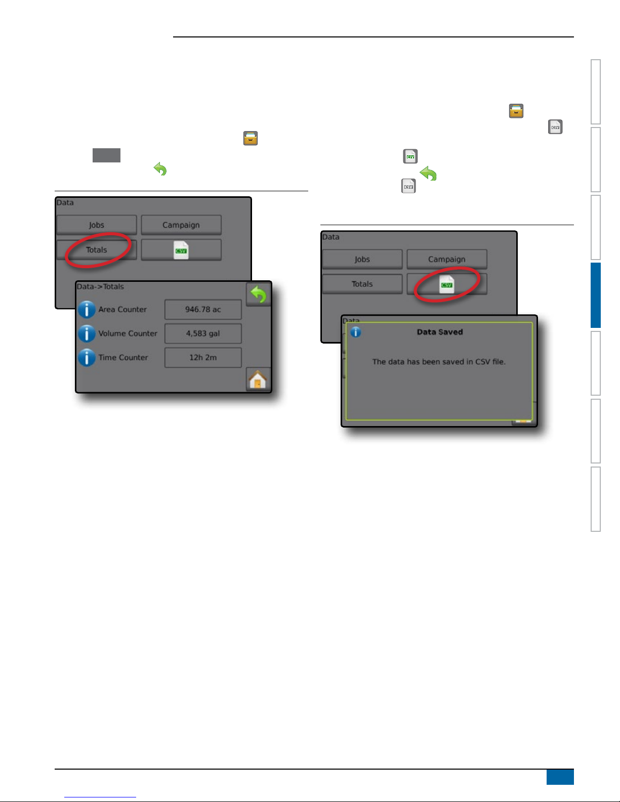
Radion 8140 Automatic Sprayer Control
Totals
Total Counters displays information for all activity on the console
regarding Applied Coverage Area, Volume of Material Applied, and
Time Traveled for all jobs. Total Counters may only be cleared in the
OEM menu.
1. From the Home screen, press the DATA button .
2. Press Totals .
3. Press RETURN arrow to return to the main Data screen.
Figure 4-6: Total Data
CSV Report
The CSV button compiles active job information to be exported as a
CSV le.
1. From the Home screen, press the DATA button .
2. Insert USB drive into the console and wait for CSV button to
activate.
3. Press CSV button .
4. Press RETURN arrow to return to the main Data screen.
NOTE: The CSV icon is not available for selection (grayed out)
until a USB drive is inserted properly.
Figure 4-7: Job Data
INTRODUCTION
OPERATIONAPPENDIX SETTINGSTOOLS CONSOLE
DATA
98-05311-ENUS R2
51
Page 58

Radion 8140 Automatic Sprayer Control
INTRODUCTION
CHAPTER 5 – CONSOLE
The CONSOLE setup is used to congure the display and cultural settings.
OPERATION DATA APPENDIXSETTINGS TOOLS
1. From the Home screen, press the CONSOLE button .
2. Select from:
►Display – congures color scheme and LCD brightness, establishes screenshot availability and calibrates the touchscreen
►Cultural – congures units, language, date and time settings
►Sound – turns the key beeps on/off
►Unlock – unlocks additional features
►About – displays the system software version
Figure 5-1: The CONSOLE Options
CONSOLE
Display
Display congures color schemes and LCD brightness, establishes
screenshot availability and calibrates the touchscreen.
1. From the Home screen, press the CONSOLE button .
2. Press Display .
3. Select from:
►User Interface Color Scheme – changes the background and
text colors on the display
►LCD Brightness – adjusts the brightness of the Console display
►Screenshot – allows screen images to save to a USB drive
►Touchscreen Calibrate – forces a touch screen calibration
4. Press RETURN arrow to return to the main Console settings
screen.
Figure 5-2: Display Options
52
www.teejet.com
Page 59

Radion 8140 Automatic Sprayer Control
Cultural
Cultural congures Language, Units, Date and Time settings.
1. From the Home screen, press the CONSOLE button .
2. Press Cultural .
3. Select from:
►Language – denes the system language
►Units – denes the system measurements
►Date – establishes the date
►Time – establishes the time
4. Press RETURN arrow to return to the main Console
settings screen.
Figure 5-3: Cultural Options
Figure 5-4: Language Selection
cs
es-ES
hu
pt-BR
de-DE
es fr-FR
it-IT
sk
en-GB
nl
INTRODUCTION
OPERATIONDATA APPENDIX SETTINGSTOOLS
en-US
pl
Language Selection
1. From the Console settings screen press Cultural .
2. From the Cultural screen press Language .
3. Select a language:
►Press the Right and Left arrows to toggle between
Language selection screens
►Press any language button to select a language and return to
the Console->Culture screen
◄Date will automatically setup to match language selection
►Press the RETURN arrow to return to the Console
settings screen or press the HOME button to return to the
Home screen.
CONSOLE
Code Language
cs Czech
da Danish
de-DE German
en-GB English (international)
en-US English (USA)
es-ES Spanish (Europe)
es Spanish (Central/South America)
fr-FR French
hu Hungarian
it-IT Italian
nl Dutch
pl Polish
pt-BR Portuguese (Brazil)
ru Russian
sk Slovak
NOTE: Some languages listed may not be available on the console.
98-05311-ENUS R2
53
Page 60

Radion 8140 Automatic Sprayer Control
Sound
INTRODUCTION
Sound enables or disables the key beep.
1. From the Home screen, press the CONSOLE button .
2. Press Sound .
3. Select to enable/disable key beep.
OPERATION DATA APPENDIXSETTINGS TOOLS
4. Press RETURN arrow to return to Console settings screen.
Figure 5-5: Sound Option
CONSOLE
About
About/Save screen displays the System Software Version.
To help troubleshoot problems in the eld, press Save to download
a text le containing current software information to a USB drive,
then e-mail the le to support personnel.
1. From the Home screen, press the CONSOLE button .
2. Press About to view data including:
◄Unit Model Number
◄Software Version
OR
3. Press Save to save the About information to a USB Drive.
“Saved version information to USB drive” message conrms the
save.
4. Press RETURN arrow to return to the main the Console
settings screen.
NOTE: The Save option is not available for selection (grayed out)
until a USB drive is inserted properly.
Figure 5-7: About Options
Unlock
Unlock gives access to advanced features using an unlock code.
Contact a local dealer for codes and specic product information.
1. From the Home screen, press the CONSOLE button .
2. Press Unlock .
3. Select a feature to unlock.
4. Enter an unlock code.
5. Restart the console.
Figure 5-6: Unlock Option
NOTE: In the example above, the unit model number is
Radion 8140 and the software version is 1.06.
54
www.teejet.com
Page 61

Radion 8140 Automatic Sprayer Control
CHAPTER 6 – TOOLS
The Tool menu allows the operator to do various calculations using a regular calculator or a unit converter. The unit converter
calculates various measurements based on area, length or volume.
1. From Home screen , press TOOLS button .
2. Select from:
►Calculator – performs mathematical calculations
►Units Converter– performs unit conversions for area, length and volume
Figure 6-1: Tools
INTRODUCTION
OPERATIONDATA APPENDIX SETTINGSCONSOLE
Figure 6-2: Calculator
Backspace
MC
MR
MS
M+
TOOLS
Figure 6-3: Units Converter
0.00
Clear
7
4
1
0
8
5
2
9
6
3
.
±
Clear All
/
*
-
+
1/x
√
2
x
=
square metres
98-05311-ENUS R2
55
Page 62

Radion 8140 Automatic Sprayer Control
Matrix Pro Console
Serial connection
Speed sensor connection
APPENDIX A – SYSTEM CONFIGURATIONS AND CONNECTIONS
INTRODUCTION
CONFIGURATIONS
The following diagram is reective of typical Radion conguration. Due to the variety of possible congurations, this should be used for
reference purposes only.
OPERATION DATA SETTINGS TOOLSCONSOLE
Figure 7-1: System Diagram
Radion
Matrix Pro & BoomPilot
Optional Accessory
Cable, BoomPilot Adapter Cable,
Radion to Matrix Pro
197-100*: Direct
197-101*: CAN/Power/Data Cable
99ET017-6** Speed Sensor Proximity, 19.7 ft (6 m)
98-50139
USB Stick
198-669 ** GPS Speed Adapter Cable
Flow/Pressure/Speed
90-02371 GPS Speed Sensor
Spray Cable -
199-315: 5 section,
26.2 ft (8 m)
199-311: 7 section,
26.2 ft (8 m)
199-319: 9 section,
26.2 ft (8 m)
Radion 8140 Sprayer Controller
(available in 5 sections,
7 sections or 9 sections)
* Unlock code necessary to activate
the BoomPilot function, contact TeeJet Technologies.
** Only one speed source at a time.
98ET05-S13-4
Extension for
Main Cable,
13.1 ft (4 m)
CONNECTIONS
Radion Console Connections
Figure 7-2: Radion Console Connections
APPENDIX
Main connection
Speed Connection On Radion Console
96ET14 Cable,
Battery to COBO,
13.1 ft (4 m)
Flow Meter
CAN connection
96ET10-8D **
Speed Sensor
Proximity,
26.2 ft (8 m)
Pressure Sensor
570-001: 145 psi (10 bar) ¼ NPT
570-002: 362.6 psi (25 bar) ¼ NPT
Table 7-1: Speed Connection
Pin No. Signal Name
2 Speed
6 +12V switched
7 Ground
Can Connection On Radion Console
56
www.teejet.com
Table 7-2: CAN Connection
Pin No. Signal Name
C +12V
D Ground
E CAN high
F CAN low
Page 63

Radion 8140 Automatic Sprayer Control
COBO power connection
Pressure sensor connection
Main Connection on Radion Console
Serial connection on Radion console
Table 7-3: Serial Connection
Pin No. Signal Name
2 Transmit
3 Receive
5 Ground
Table 7-4: Main Connection
Pin No. Signal Name
A Master
B Section 1
C Section 2
D Section 3
E Section 4
F Section 5
G Section 6
H Section 7
J Section 8
K Section 9
L n/a
M n/a
N Tank Sensor / Fill Flowmeter (optional)
P Fill Valve
R Flow
S Pressure
T Speed
U Balance Up (optional)
V +12V sensor
W Balance down (optional)
X Balance Potmeter (optional)
Y Balance Potmeter (optional)
Z Balance Potmeter (optional)
a Regulation +
b Regulation c Master in
d Ground in
e +12V in
INTRODUCTION
OPERATIONDATA SETTINGSTOOLS CONSOLE
Miscellaneous Connections
General Spray Cable Connections
Figure 7-3: General Spray Cable Connections
Console connection
Master valve and Regulation valve connections
Boom section connections
Flow meter connection
Speed sensor proximity connection
98-05311-ENUS R2
APPENDIX
57
Page 64

Radion 8140 Automatic Sprayer Control
APPENDIX B – USER SETTING NOTES
INTRODUCTION
Settings-> Job Parameters
Description User Setting
No. 1
Target Application Rates
OPERATION DATA SETTINGS TOOLSCONSOLE
No. 2
No. 3
NOTE: Go to Settings->Job Parameters->Application Rate; or go
to Settings->Machine->Implement Parameters->Tip Preset
Setup.
Settings-> Machine-> Filling
Description User Setting
Density Type
Density Factor (Fertilizer)
NOTE: Go to Operation->Filling (1) and (2) (via Tank icon) or go to
Settings->Machine->Filling (1) and (2).
Settings-> Machine-> Operation
Description User Setting
Application Rate Step
Speed Source
Simulated speed
Minimum Speed
NOTE: Go to Settings->Machine->Operation.
Settings-> Machine-> Implement Parameters
Section Conguration
Description User Setting
Number of Tips Section 1
Number of Tips Section 2
APPENDIX
Number of Tips Section 3
Number of Tips Section 4
Number of Tips Section 5
Number of Tips Section 6
Number of Tips Section 7
Number of Tips Section 8
Number of Tips Section 9
Number of Tips Section 10
Number of Tips Section 11
Number of Tips Section 12
Number of Tips Section 13
NOTE: Go to Settings->Machine->Implement Parameters-> Section
Configuration.
The number of available sections is dependent upon the
console model.
Tip Preset Setups
Tip Preset No. 1 User Setting
Tip Series
Tip Capacity
Low Pressure Limit
High Pressure Limit
Reference Flow
Reference Pressure
Tip Preset No. 2 User Setting
Tip Series
Tip Capacity
Low Pressure Limit
High Pressure Limit
Reference Flow
Reference Pressure
Tip Preset No. 3 User Setting
Tip Series
Tip Capacity
Low Pressure Limit
High Pressure Limit
Reference Flow
Reference Pressure
Tip Preset No. 4 User Setting
Tip Series
Tip Capacity
Low Pressure Limit
High Pressure Limit
Reference Flow
Reference Pressure
Tip Preset No. 5 User Setting
Tip Series
Tip Capacity
Low Pressure Limit
High Pressure Limit
Reference Flow
Reference Pressure
NOTE: Go to Settings->Machine->Implement Parameters-> Tip
Preset Setup to access tip preset setups.
Regulation Parameters
Description User Setting
Course valve calibration
Fine valve calibration
Tip Spacing
Regulation Mode
NOTE: Go to Settings->Machine->Implement Parameters->
Regulation Parameters.
58
www.teejet.com
Page 65

Radion 8140 Automatic Sprayer Control
Settings-> Machine-> Calibrations
Implement Speed Sensor
Description User Setting
Calibration Number
NOTE: Go to Settings->Machine->Calibrations->Implement Speed
Sensor. Some options may not be available depending upon
OEM sensor settings.
INTRODUCTION
Flow Sensor
Description User Setting
Calibration Number
Low Flow Limit
High Flow Limit
NOTE: Go to Settings->Machine->Calibrations->Flow Sensor. Some
options may not be available depending upon OEM sensor
settings.
Liquid Pressure Sensor - Maximum Pressure Option
Description User Setting
Maximum Pressure
Reference Pressure
NOTE: Go to Settings->Machine->Calibrations->Liquid Pressure
Sensor->Maximum Pressure sensor. Some options may not
be available depending upon OEM sensor settings.
Fill Flow Sensor
Description User Setting
Calibration Number
NOTE: Go to Settings->Machine->Calibrations->Fill Flow Sensor.
Some options may not be available depending upon OEM
sensor settings.
OPERATIONDATA SETTINGSTOOLS CONSOLE
Tank Level Sensor
NOTE: Manual calibration is not available for any Tank Level Sensor
calibrations.
Settings-> Machine-> Alarms
Description User Setting
Minimum Tank Content
Flow/Pressure Cross Check
Section Output Low
NOTE: Go to Settings->Machine->Alarms.
APPENDIX
98-05311-ENUS R2
59
Page 66

Radion 8140 Automatic Sprayer Control
APPENDIX C – ALARM CONFIGURATIONS
INTRODUCTION
Code Message / Condition Possible Solution Console Path
Check ow sensor from test menu. Check components and
programming steps related to ow.
Check ow sensor from test menu. Check components and
programming steps related to ow.
Check components and programming steps related to
implement or process registering a calibration error.
Select Water for tank contents or change Fertilizer density
No..Check components and programming steps related to
content.
Increase speed. Check components and programming
steps related to speed.
Check components and programming steps related to
implement or process registering a pressure error.
Increase speed. Check or clean tips. Check components
and programming steps related to ow.
Rell tank. Check all components and programming steps
related to contents.
Select a new target rate. Use larger tips. Check
components and programming steps related to rates.
Select a lower target rate. Check components and
programming steps related to rates.
Check components and programming steps related to
pressure.
Check components and programming steps related to
pressure.
Check components and programming steps related to
pressure.
Check components and programming steps related to
pressure.
Check ow sensor from test menu. Check components and
programming steps related to pressure.
Check ow sensor from test menu. Check components and
programming steps related to pressure.
Check components and programming steps related to
speed.
Check GPS source for power/satellite reception. If no GPS
source, change speed source. Check components and
programming steps related to speed.
Check BoomPilot for power. Test BoomPilot under test
menu.
Current operation mode is different than standard
operation. If this is undesired, change mode to automatic
under test menu.
Current operation mode is different than standard
operation. If this is undesired, check section switches
are ipped up (ON). Check sections under test menus.
Congure sections. Check components and programming
steps related to power.
Check components and programming steps related to
sections.
Check Master Switch if ipped up (ON). Check all
components and programming steps related to Master
Switch.
OPERATION DATA SETTINGS TOOLSCONSOLE
APPENDIX
1 No Flow Pulses
2 Low Liquid Pressure
4 Calibration Error
Density Not Equal To Water
5
(1 kg/L or 8.34 lb/gal)
6 Below Minimum Speed
7 Pressure Based
8 Low Flow
9 Tank Almost Empty
10 Target Rate Impossible to Reach
11 Actual Rate Too High
12 Minimum Regulation Pressure
13 Maximum Regulation Pressure
14 Pressure Too Low
15 Pressure Too High
16 Pressure/Flow Check Check components and programming steps related to ow.
19 Liquid Pressure Too Low
20 Liquid Pressure Too High
21 No Speed Signal
31 Work Not Possible
34 Save Error Insert or reset a USB device if saving to a USB port.
36 Can Speed Missing
45 Boompilot Unit Not Responding
46 Boompilot Unit In Manual Mode
47 Not All Sections On
49 Section Output Failure
50 Master Output Failure
Settings->Diagnostics->Test Inputs (1)->
Flow Sensor
Settings->Machine->Implement Parameters->
Tip Preset Setup (2) or Settings->Machine->
Calibrations or Settings->Diagnostics->Test Inputs
(2)->Liquid Pressure Sensor
Settings->Machine->Calibrations - check sensors
Operation->Filling (1) or Settings->Machine->
Filling (1)
Settings->Machine->Operation or Settings->
Machine-> Calibrations->Implement Speed Sensor
Settings->Diagnostics->Test Inputs or Settings-> Machine>Implement Parameters->Tip Preset Setup (2)
Settings->Diagnostics->Test Inputs or Settings-> Machine>Implement Parameters->Tip Preset Setup (2)
Operations->Tank->Filling (1) or Settings->
Machine-> lling (1) and (2) or Settings->
Machine-> Alarms-> Minimum Tank Contents
Operation->Target rates or Settings->Job Parameters
Operation->Target rates or Settings->Job Parameters
Settings->Machine->Implement Parameters-> Regulation
Parameters
Settings->Machine->Implement Parameters-> Regulation
Parameters
Settings->Machine->Implement Parameters->
Tip Preset Setup (2)
Settings->Machine->Implement Parameters-> Tip Preset
Setup (2)
Settings->Diagnostics->Test Inputs or Settings-> Machine>Calibrations
Settings->Machine->Implement Parameters->
Tip Preset Setup (2) or Settings->Machine->
Calibrations or Settings->Diagnostics->Test Inputs
(2)->Liquid Pressure Sensor
Settings->Machine->Implement Parameters->
Tip Preset Setup (2) or Settings->Machine->
Calibrations
Settings->Machine->Calibrations->Implement Speed
Sensor
Settings->Machine->Operation->Speed Source
Settings->Diagnostics->Test BoomPilot
Settings->Diagnostics->Test BoomPilot
Settings->Diagnostics->Test Outputs (2) or Settings->
Diagnostics->Test Inputs (3)->Section Switches or Settings-
>Machine->Implement Parameters->Section Conguration
Settings->Diagnostics->Test Outputs (2)
Settings->Diagnostics->Test Inputs (3)->Master Switch
60
www.teejet.com
Page 67

Radion 8140 Automatic Sprayer Control
Code Message / Condition Possible Solution Console Path
51 Fill Valve Output Failure
52 Low Supply Voltage Check voltage supply under Diagnostics. Settings->Diagnostics->Supply Voltage
APPENDIX D – UNIT SPECIFICATIONS
Check ll valve under test menus. Check components and
programming steps related to ll valve.
Settings->Diagnostics->Test Outputs (2)->Fill Valve
INTRODUCTION
Dimensions Radion 8140, 5-section 228.6 x 158.0 x 61.6 mm
Radion 8140, 7-section 228.6 x 158.0 x 61.6 mm
Radion 8140, 9-section 254.0 x 158.0 x 61.6 mm
Weight Radion 8140, 5-section 1.3 kg
Radion 8140, 7-section 1.3 kg
Radion 8140, 9-section 1.9 kg
Connector Power/CAN 8-pin Conxall
Speed/status 8-pin Conxall
Main 28-pin
Serial 9-pin
Environmental Storage -10 to +70°C
Operating 0 to +50°C
Humidity 90% non-condensing
Display Radion 8140 320 x 240 resolution 4.3"
Input/Output USB 2.0
Power Requirement < 9 watts @ 12 VDC
OPERATIONDATA SETTINGSTOOLS CONSOLE
98-05311-ENUS R2
APPENDIX
61
Page 68

RADION 8140
RADION 8140
USER MANUAL
USER MANUAL
Product Upgrades Available
• Matrix Pro® Guidance
• BoomPilot® Automated Boom Section Control
www.teejet.com
98-05311-ENUS-LT R2 English
© TeeJet Technologies 2017
 Loading...