

Page 1

F I E L D P I L O T®
U S E R M A N U A L
Assisted Steering Hydraulic Installation Manual for
Vehicle Kit Number 91-02340
Fits Only AGCO Gleaner R62/R65 (after S/N 66000) and
R72/R75 (after S/N 76000) Combines
Page 2

Page 3

FieldPilot
®
FIELDPILOT®
Copyrights
© 2010 TeeJet Technologies. All rights reserved. No part of this document or the computer programs
described in it may be reproduced, copied, photocopied, translated, or reduced in any form or by any
means, electronic or machine readable, recording or otherwise, without prior written consent from TeeJet
Technologies.
Trademarks
Unless otherwise noted, all other brand or product names are trademarks or registered trademarks of their
respective companies or organizations.
Limitation of Liability
TEEJET TECHNOLOGIES PROVIDES THIS MATERIAL “AS IS” WITHOUT WARRANTY OF ANY KIND,
EITHER EXPRESSED OR IMPLIED. NO COPYRIGHT LIABILITY OR PATENT IS ASSUMED. IN NO
EVENT SHALL TEEJET TECHNOLOGIES BE LIABLE FOR ANY LOSS OF BUSINESS, LOSS OF PROFIT,
LOSS OF USE OR DATA, INTERRUPTION OF BUSINESS, OR FOR INDIRECT, SPECIAL, INCIDENTAL,
OR CONSEQUENTIAL DAMAGES OF ANY KIND, EVEN IF TEEJET TECHNOLOGIES HAS BEEN
ADVISED OF SUCH DAMAGES ARISING FROM TEEJET TECHNOLOGIES SOFTWARE.
www.teejet.com
1
Page 4
FieldPilot
®
PREPARATION
1. Before beginning the installation, thoroughly clean the vehicle to remove dirt and contaminants that might
get into the hydraulic circuit.
2. Park the vehicle on a clean, level oor with adequate clearance to work around.
3. Do not attempt to loosen any hydraulic ttings while the engine is running.
4. Allow the motor and the hydraulics to cool until it is no more than warm to the touch before proceeding.
5. Prior to loosening any hydraulic ttings, be sure to have the appropriate plugs and caps available in order
to limit loss of hydraulic uid from the open ttings.
PREVENT HYDRAULIC SYSTEM CONTAMINATION. It is essential to thoroughly clean hydraulic
system ttings and hose connections prior to disconnecting or removing them. Use a spray
cleaner such as “Brake Clean” to prevent hydraulic system contamination. Note that o-rings used
on ORB and ORFF type ttings may be damaged by solvent cleaners such as “Brake Clean”. If a tting is to
be cleaned internally, the o-ring should rst be removed and cleaned with a berless cloth.
TO AVOID EXCESS LEAKAGE, DO NOT TURN THE STEERING WHEEL WHILE THE
FITTINGS ON THE MANUAL STEERING VALVE ARE DISCONNECTED.
WARNING: HOT, HIGH PRESSURE FLUID HAZARD. Hydraulic oil may be hot and under
extreme pressure. To prevent serious injury or death, relieve system pressure and allow the
system to cool before repairing or disconnecting. Wear proper hand and eye protection when
searching for leaks, using wood or cardboard instead of hands. Keep all hydraulic components in good repair.
WARNING: PINCH POINT HAZARD! To prevent serious injury or death, avoid unsafe practice
while manually operating hydraulic steering circuits. Keep others away and stay clear of
mechanical steering linkages.
2
www.teejet.com
Page 5

FieldPilot
KIT CONTENTS
Unpack the installation kit and identify the required parts.
Item Part Number Description Quantity
A 32-04040 Switch, Engage/Disengage ......................................................................................1
B 350-0037 Washer, Flat - 3/8” SST ...........................................................................................4
C 350-0627 Bolt, Hex 3/8-16 x 1”, SST .......................................................................................2
D 35-02189 Valve, FieldPilot PWM, 3.2GPM, OC .......................................................................1
E 45-07703 Harness, SCM .........................................................................................................1
F 45-10103 Harness, Valve .........................................................................................................1
G 60-04089 Bolt, Hex- 3/8-16 x 3-3/4” SST .................................................................................2
H 60-07027 Nut, NyLock 3/8-16, SST .........................................................................................4
I 65-05153 Bracket, Hyd. Mount ................................................................................................1
J 68-01135 Hose, Hyd. - 1/2” x 35”, #8FJIC x #8FJIC 90º .........................................................1
K 68-01155 Hose, Hyd. - 3/8” x 66”, #6FJIC x #6FJIC 90º .........................................................2
L 68-01156 Hose, Hyd. - 5/8” x 64”, #10FJIC x #10FJIC 90º .....................................................2
M 68-02009 Adapter, Hyd. Run Tee - #8 JIC ...............................................................................1
N 68-02022 Adapter, Hyd. Run Tee - #6 JIC ...............................................................................2
O 68-02046 Adapter, Hyd. - #10MJIC x #12MORB .....................................................................2
P 68-02078 Adapter, Hyd. 90º - #6MJIC x #6FJIC ......................................................................2
Q 68-02082 Adapter, Hyd. - #6MJIC x #8MORB .........................................................................2
R 68-02093 Adapter, Hyd. 90º - #8MJIC x #8FJIC ......................................................................1
S 68-02094 Adapter, Hyd. - #8MJIC x #8MORB .........................................................................1
T 90-50013 Cable Tie Kit, 15 ......................................................................................................1
U 91-07011 Steering Wheel Switch Kit .......................................................................................1
V 98-05131 Installation Manual FP, Gleaner R62/R65/R72/R75.................................................1
®
www.teejet.com
3
Page 6
FieldPilot
®
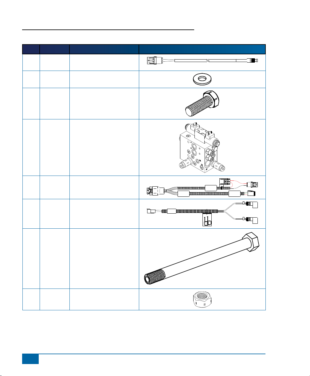
Item Part # Description Illustration
A 32-04040 Switch, Engage/Disengage,
Momentary
B 350-0037 Washer, Flat - 3/8" SST
C 350-0627 Bolt, Hex 3/8-16 x 1", SST
D 35-02189 Valve, FieldPilot PWM,
3.2GPM, OC
E 45-07703 Harness, SCM
F 45-10103 Harness, Valve
G 60-04089 Bolt, Hex- 3/8-16 x 3-3/4"
SST
H 60-07027 Nut, NyLock 3/8-16, SST
45-10103
DC:xx/xx
SCM Power I/O
45-07703
DC: xx/xx
Power
Valve Output
A
B
4
www.teejet.com
Page 7

Item Part # Description Illustration
I 65-05153 Bracket, Hyd. Mount
J 68-01135 Hose, Hyd. - 1/2" x 35",
#8FJIC x #8FJIC 90º
K 68-01155 Hose, Hyd. - 3/8" x 66",
#6FJIC x #6FJIC 90º
L 68-01156 Hose, Hyd. - 5/8" x 64",
#10FJIC x #10FJIC 90º
M 68-02009 Adapter, Hyd. Run Tee - #8
JIC
FieldPilot
®
N 68-02022 Adapter, Hyd. Run Tee - #6
JIC
O 68-02046 Adapter, Hyd. - #10MJIC x
#12MORB
www.teejet.com
5
Page 8

FieldPilot
Item Part # Description Illustration
P 68-02078 Adapter, Hyd. 90º - #6MJIC
Q 68-02082 Adapter, Hyd. - #6MJIC x
R 68-02093 Adapter, Hyd. 90º - #8MJIC
S 68-02094 Adapter, Hyd. - #8MJIC x
®
x #6FJIC
#8MORB
x #8FJIC
#8MORB
T 90-50013 Cable Tie Kit, 15
U 91-07011 Steering Wheel Switch Kit
V 98-05131 Installation Manual FP, Gleaner R62/R65/R72/R75
6
www.teejet.com
Page 9

Figure 1-1: Hydraulic Diagram
Manual Steering Valve
Tank
FieldPilot
®
L
R
L
EF
K
B
K
A
FieldPilot Valve
LS
T
P
LS
CF
L
P
J
T
EF
Priority Valve
Auxiliary
Pump
P
T
Valve Stack
Existing Hoses
Hoses From Kit
www.teejet.com
7
Page 10

FieldPilot
®
INSTALLATION
If there are questions concerning the installation of the FieldPilot system on this vehicle, or due to
the changes in component specications the parts supplied in the kit are not exactly as presented
in this document, please contact your dealer or TeeJet Customer service representative for
clarication before installation. TeeJet Technologies is not responsible for misuse or incorrect installation of
the system.
NOTE: BE VERY CAREFUL TO ABSOLUTELY SECURE ALL CABLES AND HOSES SO THAT THEY
DON’T INTERFERE WITH THE MANY MOVING PARTS OF THE MACHINE!
Overview of the Machine
• The valve will mount on the right side of the machine.
• The P, EF, & T connections will be on the right side of the machine.
• The Left & Right steer connections will be at the orbital under the cab.
NOTE: All references to left and right are stated as if the user is seated in the driver’s seat.
Figure 1-2: Overview of the Machine
GPS
Hydraulic
Connections
8
www.teejet.com
FieldPilot
Valve
Page 11

FieldPilot
®
1. PREPARE THE FIELDPILOT VALVE
Install adapters (O) in the P and EF ports. Install adapters (Q) in the A and B ports, then install adapter (S)
in the T port. Next attach adapters (P) to adapters (Q) in the A & B ports. Finally attach adapter (R) to
adapter (S) in the T port.
Figure 1-3: Prepare the FieldPilot Valve
P
Q
P
Q
O
O
S
R
2. MOUNT THE FIELDPILOT VALVE
The FieldPilot valve will be mounted on the outside of the right side frame rail that runs forward underneath
the cab. Depending on the machine model, there may already be one hole in the frame, in which case this
hole will be the rear-most hole used to mount valve bracket (I).
Figure 1-4: Identify Mounting Hole
Bracket (I)
www.teejet.com
9
Page 12

FieldPilot
Be careful to identify which face on valve bracket (I) mounts to FieldPilot valve (D). Using the other face of
the bracket as a template, mark and then drill the required 7/16” hole(s) in the frame and secure the bracket
to the frame using hardware (B, G & H).
Using hardware (B, G & H), mount the FieldPilot valve (D) to the valve bracket (I) making sure that the
solenoid valve coils face toward the rear of the machine.
Figure 1-5: Mount FieldPilot Valve
®
B, G & H
3. DISCARD EXISTING EXCESS FLOW HOSE
Locate the existing hose that runs from the Excess Flow (EF) port of the Priority Valve to the hydraulic valve
stack and remove it. USE PLASTIC CAPS TO PREVENT EXCESS LEAKAGE FROM THE OPEN PORTS.
Figure 1-6: Discard Existing Excess Flow Hose
10
www.teejet.com
Priority valve
Excess Flow port
Remove and discard
existing hose
Page 13

FieldPilot
4. INSTALL EXCESS FLOW HOSE
Connect hose (L) to adapter (O) installed in the EF port on the FieldPilot Valve. Connect the other end of
this hose to the -10JIC adapter on the hydraulic valve stack left open when the original excess ow hose
was discarded. Take care routing the hose to be sure it is clear of all drive belts and cannot rub on other
components.
Figure 1-7: Install Excess Flow Hose
®
Hose L for excess ow
Hose L for excess ow
5. INSTALL PRESSURE HOSE
Connect hose (L) to adapter (O) installed in the P port of the FieldPilot valve. Connect the end of the hose
to the EF port of the Priority valve left open when the original excess ow hose was discarded.
Figure 1-8: Install Pressure Hose
Hose L for Pressure
Hose L for Pressure
www.teejet.com
11
Page 14

FieldPilot
®
6. INSTALL TANK HOSE
Locate the Tank oil connection under the cab and above the feeder housing. If there is an unused (capped)
connection point, connect hose (J) to this connection point or use optional run tee adapter (M) to create an
additional connection point. Connect hose (J).
NOTE: The machine may not be exactly as illustrated due to the absence/presence of a number of machine
options.
Connect the other end of hose (J) to adapter (R) installed in the T port of the FieldPilot valve. USE
PLASTIC CAPS TO PREVENT EXCESS LEAKAGE FROM THE OPEN PORTS.
Figure 1-9: Install Tank Hose
Hose J
Hose J
7. INSTALL LEFT AND RIGHT STEER HOSES
Locate the left and right steer hoses where they connect to the right side of the orbital valve (ports closest to
the 1/4” Load Sense hose). Taking care to remember the port that each of the original hoses was connected
to, remove the hose. Install run tee (N) to the adapter on the orbital and connect the original hose to the run
on the new run tee. Connect the 90° end of hose (K) to the branch of the run tee. Connect the other end
of hose (K) to adapter (P) installed in the A and B ports of the FieldPilot valve. Repeat this process for the
second run tee and hose. Do not be concerned about which hose (K) goes to which port on the orbital or
FieldPilot valve.
12
www.teejet.com
Page 15

Figure 1-10: Install Left and Right Steer Hoses
Hose K
FieldPilot
®
N
Hose K
8. SECURE HOSES
Be sure all hoses are routed in a manner that prevents them from rubbing on other parts of the machine. Use
the heavy tie-straps provided to secure the hose away from moving parts.
9. INSTALL THE VALVE CONTROL CABLE
Connect the FieldPilot valve control cable (F) to the solenoids on the FieldPilot valve and route the cable
into the cab to connect to the SCM harness. Do not be concerned at this time about which connector is
connected to which solenoid coil.
Figure 1-11: Install Valve Control Cable
Valve control cable
www.teejet.com
13
Page 16

FieldPilot
®
10. INSTALLATION OF ENGAGE/DISENGAGE SWITCH
Connect item (A) to the connector on the SCM harness labeled Remote Engage/Disengage. Install the push
button in a location that is easily accessible during operation of the machine. This switch (A) is not required
if the optional foot switch 32-04020 is used.
Figure 1-12: Engage/Disengage Switch
11. INSTALL STEERING DISENGAGE SWITCH KIT 9107011
Remove the left side steering column cover below the steering wheel. Cut the provided self-adhesive
magnets in half so they t better, and stick at least two of these magnets to the shaft immediately above the
universal joint. Bend the aluminum mounting bracket as illustrated, and mount the disengage sensor on the
backside of the steering column as shown (hose clamp not included).
Set the clearance between the sensor and magnets to 1/8” and rotate the steering wheel in both directions
to be sure that the sensor does not contact the magnets or the shaft. Connect the sensor to the Steering
Control Module Cable labeled ‘Steering Wheel Sense’ and secure the cables in position so that they cannot
interfere with the rotation of the steering shaft, or the full range of the fore/aft and extended/retracted
positions of the adjustable steering column. It may be necessary to remove the convoluted tubing from the
sensor cable in order to route the cable nicely inside the steering column cover.
Note: These illustrations are for the R75 model. Other models may vary.
14
www.teejet.com
Page 17

Figure 1-13: Install Steering Disengage Switch (Kit 91-07011)
Magnet
FieldPilot
®
Sensor
www.teejet.com
15
Page 18

FieldPilot
®
12. RECOMMENDED ELECTRONICS INSTALLATION
The SCM should be mounted as far forward in the cab as possible. The control console can be mounted to
the operator’s preference. The GPS antenna should be mounted as far forward as possible on top of the
cab on a metal surface of at least 4” square.
Figure 1-14: Recommended Electronics Installation
GPS
SCM
13. VERIFY OPERATION OF HYDRAULICS AND SET THE STEERING
CONTROL RATE
Clean and pick up the area around the vehicle and make certain that it is safe to operate. Start the engine
and check hydraulic connections for leaks. Rotate the steering wheel from one extreme to the other and
back to center, check for leaks. While steering through the extremes of movement, check the cables and
hoses for wear points and strain, adjust as necessary.
PLEASE NOTE THE FOLLOWING RECOMMENDATION FROM AGCO:
After servicing of the steering cylinders and/or hydraulic hoses, any air that may be trapped in the hydraulic
system must be bled in order to provide smooth, instantaneous operation of the steering system. To bleed
the steering cylinders and/or hydraulic hoses, proceed as follows:
Jack up the rear axle (on both sides) until the rear wheels are off the ground. Securely block the rear
axle. Start the engine and turn the steering wheel as if making a right hand turn (as far as it will go) until
the left hand steering cylinder is completely retracted and the right hand steering cylinder is completely
extended. Turn the steering wheel as if making a left hand turn (as far as it will go) until the left hand
steering cylinder is completely extended and the right hand steering cylinder is completely retracted.
Repeat these steps until the steering cylinders operate smoothly and instantaneously in both directions.
16
www.teejet.com
Page 19

FieldPilot
The nal oil ow rate adjustment is accomplished through the Matrix console. The
target lock to lock time is 8 seconds and the valve frequency is 110. Refer to the
Matrix manual for further instructions.
NOTE: To activate the manual overrides, a tool such as a small screwdriver or allen wrench must be inserted
into the end of the coil to depress the override button.
WARNING: PINCH POINT HAZARD! To prevent serious injury or death, avoid unsafe practice
while manually operating hydraulic steering circuits. Keep others away and stay clear of
mechanical steering linkages.
®
14. COMPLETE ELECTRONIC INSTALLATION
Refer to the owner’s manual supplied with the automated steering system to complete the electronic
installation and setup.
www.teejet.com
17
Page 20

F I E L D P I L O T®
U S E R M A N U A L
A series of equipment-specic hydraulic installation kits have been
developed to work in conjunction with your assisted steering system. This
kit contains the necessary components and instructions to install assisted
steering hydraulics on the AGCO Gleaner R62/R65 (after S/N 66000)
and R72/R75 (after S/N 76000) Combines. Please review this manual
thoroughly before beginning the installation process.
1801 Business Park Drive
Springeld, Illinois 62703 USA
Tel: (217) 747-0235 • Fax: (217) 753-8426
www.teejet.com
98-05131 R2
© TeeJet Technologies 2010
 Loading...