

Page 1
98-05086
R1
PRODUCT WARRANTY
MIDWEST TECHNOLOGIES ILLINOIS, LLC (also known as Mid-Tech & TeeJet) warrants to the
original purchaser that the product purchased shall be free of defect in material or workmanship. If the
product proves to be defective within the warranty period the purchaser must return, freight prepaid, said
product to Midwest Technologies within thirty (30) days after such defect is discovered. Upon inspection
and examination by Midwest Technologies, and at its option, the product shall be repaired or replaced,
with a new or comparable product. No product will be considered defective if it substantially fulfills the
performance specifications. Purchaser shall be responsible for all required maintenance service in accordance
with procedures outlined in Midwest Technologies’ product operator manual or service bulletins.
All product(s) replaced or repaired under warranty shall carry the remainder of the warranty left on the
original purchase. All out of warranty product(s) serviced for fee or goodwill will have ninety (90) days
of warranty. The ninety (90) days shall begin on the date serviced by Midwest Technologies.
Warranty periods for Midwest Technologies products shall be:
TeeJet and Mid-Tech Control Consoles – 2 ½ years
Mid-Tech Switch Boxes – 2 ½ years (3, 5, 9 booms)
All other products – 12 months (unless otherwise noted)
WARRANTY LIMITATIONS AND EXCLUSIONS
Midwest Technologies will have no warranty obligation hereunder if the product is subjected to abuse,
misuse, improper or abnormal usage, acts of God, faulty installation, or improper maintenance as outlined
in Midwest Technologies’ product operator manual or service bulletins. Consumable items (items that are
used during normal operation) such as light bulbs, batteries, etc., and expendable items (items which wear
out in normal use) such as injection pump tubes, flow meter bearings, etc., will not be covered by warranty.
For products that come in direct contact with chemical, the specific recommendations contained in Midwest
Technologies product bulletins must be adhered to, or this warranty is void. Any repairs or alterations,
other than those provided by Midwest Technologies and/or its authorized representatives, will void the
warranty. Midwest Technologies neither assumes nor authorizes anyone to assume for it any other obligation
or liability in connection with said product.
DISCLAIMER OF UNSTATED WARRANTY
98-05086
R1
Midwest Technologies
MT 600 PISTON INJECTION PUMP
INSTALLATION & SETUP
INSTALLATION
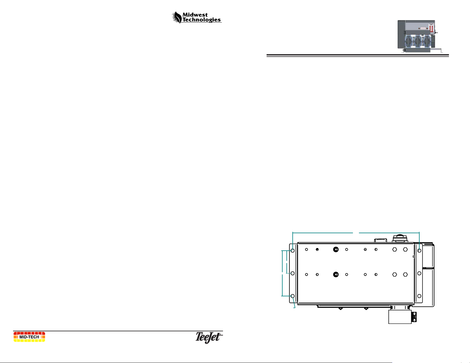
MOUNTING
The MT 600 injection pumps must be located as close as possible to the
point where the chemicals are injected into the main boom supply line. As
close to the delivery point as possible is the preferred injection point. A
consideration should be made to use check valves between the pump and
injection point as well as ahead of the injection point in the main flow
line (See the pluming diagram on page 6). Another consideration is the
location for the chemical containers must also be given, keeping the
distance between the MT 600 pump and the chemical container to a
minimum.
Once the location for the Legacy injection pump is selected, orient the
assembly so that the pump cover is easily opened, allowing access for
service. All sides of the pump may need to be accessible for service. The
pump must be mounted upright.
5oz of SAE 10w 30 oil must be added to each pump head via the red cap
port prior to operation. Oil should be visible and never overfilled
above 1/2 of the viewing window.
Figures 1 and 2 provide measurements to help you place the mounting
holes for the pumps.
The warranty printed above is the only warranty applicable to this purchase. Midwest Technologies’
warranty cannot be modified by any person or entity, including without limitation, any distributor or retailer
of Midwest Technologies. All other warranties, express or implied, including but not limited to, the implied
warranties of merchantability and fitness for a particular purpose, are disclaimed.
LIMITATION OF LIABILITY
It is understood and agreed that Midwest Technologies’ liability, whether in contract, in tort, under any
warranty, in negligence or otherwise, shall not exceed the return of the amount of the purchase price paid
by purchaser and under no circumstances shall Midwest Technologies be liable for special, indirect or
consequential damages. In particular, Midwest Technologies shall not be liable for damage to crops as the
result of misuse or negligence in the application of chemicals or operation of Midwest Technologies products.
The price stated for the equipment is a consideration in limiting Midwest Technologies’ liability. No
action, regardless of form, arising out of the transactions under this agreement may be brought by purchaser
more than one year after the cause of action has occurred.
Midwest Technologies Illinois, LLC
2864 Old Rochester Rd. - Springfield, IL 62703
®
Phone - (217) 753-8424 * Fax - (217) 753-8426
12
14.00
2.50
5.00
O
.38
(6 Plcs.)
Fig. 1: Bottom Template
1
Page 2
98-05086
R1
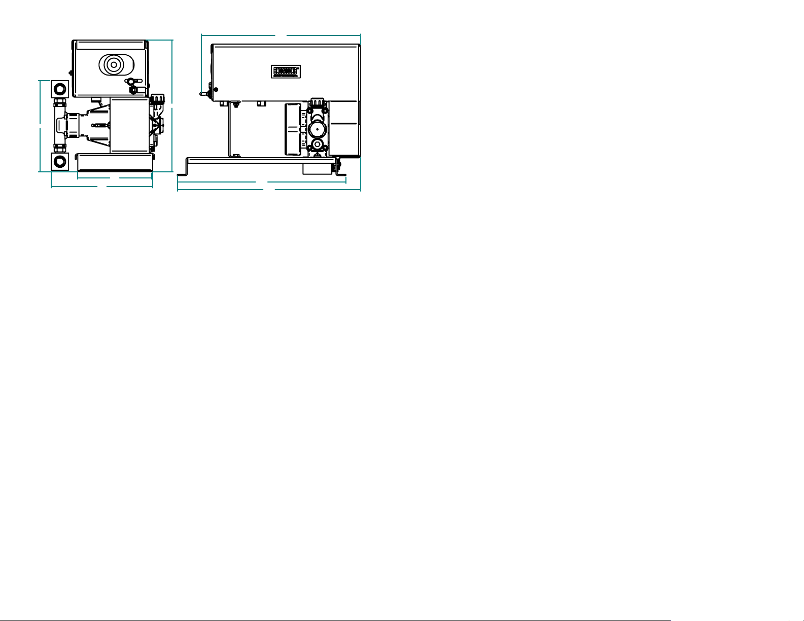
7.91
11.43
14.00
98-05086
R1
NOTES
6.40
8.80
14.63
15.91
Fig. 2: Side Template
NOTE: Secure each pump firmly to eliminate vibration and possible
damage to the connecting hoses and cables.
PLUMBING
See the sample plumbing diagram on page 6 for suggestions on how to
plumb the system.
CABLING
Each MT600 injection pump comes with two cables, a pump control cable
and a pump power cable. See the sample system diagrams on pages 7 and 8
for suggestions on how the system should be connected.
Route all cables carefully, avoiding moving parts, excessive heat and
exposure to tree limbs, stubble, or other debris. Allow enough slack at
all pivot points to prevent pinching or stretching the cables.
Secure the cables in place with cable fasteners and/or cable clamps.
Pump Control Cables: When the injection pumps have been designated
#1 , #2, etc., Midwest Technologies suggests the cable tags be marked
accordingly (use a permanent ink - water proof marker). Carefully route the
cable to the console (TASC system) or Product Control Module (Legacy
system).
Pump Power Cable: Route each power cable to the vehicle battery (12
VDC only). Attach the red lead (fused) to the positive post and the black
lead to the negative post of the battery.
2
11
Page 3

98-05086
R1
CALIBRATION NUMBERS
SETUP
98-05086
R1
Pumps:
1. _____ 2. _____ 3. _____ 4. _____ 5. _____ 6. _____
Swath 1 - Booms:
1. _____ 3. _____ 5. _____ 7. _____ 9. _____
2. _____ 4. _____ 6. _____ 8. _____
Swath 2 - Booms:
1. _____ 3. _____ 5. _____ 7. _____ 9. _____
2. _____ 4. _____ 6. _____ 8. _____
Swath 3 - Booms:
1. _____ 3. _____ 5. _____ 7. _____ 9. _____
2. _____ 4. _____ 6. _____ 8. _____
Swath 4 - Booms:
1. _____ 3. _____ 5. _____ 7. _____ 9. _____
SELECTING PROPER P UMP SIZE
Use the following formula to determine the flow capacity requirements of
the pump; then check the Pump Size Selection Chart (Fig. 3) for the proper
pump size.
Pump Cap.= Max. Boom Width x Max. Speed x Chemical Rate x (.00202)
(Oz./Min.) = (Ft.) x (MPH) x (Oz./Acre) x (.00202)
Example: A sprayer with 35 ft. booms, traveling at a maximum speed of
14 mph and applying 1 quart of chemical per acre would require a maximum pump capacity of 31.67 Oz./Min. (i.e. 35 ft. x 14 mph x 32 oz./ac. x
.00202 = 15.8 oz./min.). Referring to the Pump Size Selection Chart we
find that a 1Pump Head pump would be sufficient for this rate. However, if
you needed to apply 100 oz./ac. of chemical, you should use the 2 Head
pump; (35 ft. x 14mph x 100 oz./ac. x .00202 = 98.98 oz./min. exceeds the
recommended range of the smaller 1 Head Pump).
PUMP SIZE SELECTION CHART for MT 600 PUMP
270
2 Head Pump
2 4 6 8
4 Head Pump
3 Head Pump
1.2
.9
.6
1 Head Pump
PUMP SIZE (# of Pump Heads)
.3
.2 .4 .6 .8
1 10 20 30 40 50 100 150 200 250 3000
200
135
65
MAX. FLOW RATE (Oz. / Min.)
Fig. 3: Pump Size Chart
TYPICAL CALIBRATION NUMBERS
2. _____ 4. _____ 6. _____ 8. _____
Swath 5 - Booms:
1. _____ 3. _____ 5. _____ 7. _____ 9. _____
2. _____ 4. _____ 6. _____ 8. _____
DISTANCE: _______ FLOW METER: _______
10
Typical calibration numbers for the various pump heads listed above are:
TASC Legacy
• 1 Pump Head 10.8 340
• 2 Pump Head 4.4 170
• 3 Pump Head 3.1 115
• 4 Pump Head 2.4 85
NOTE: When adding a pump head to and existing pump there two types of
heads. Contact your MID-TECH dealer to determine which head is needed.
3
Page 4

98-05086
C
R1
CALIBRATION
Refer to your TASC 6300/6600, TASC 6500, or Legacy 6000 console user
guide for specific calibration instructions related to your specific console.
When you see a reference to placing a magnet on the motor control
module or PCM (Product Control Module), press and hold the Calibrate
switch on the MT 600 pump instead. You can record your system calibration numbers on page 10.
alibration
Switch
98-05086
R1
MT600 PISTON PUMP GENERAL SPECIFICATIONS
Product Description :
Pump T ype : Positive Displacement Piston Pump
V ersatility : Modular, serviceable, and compatible with
various controllers
Performance Characteristics :
Response : Chemical moves immediately when
motor is driven
Motor Speed : 0 to 225 rpm at 12.5 Vdc
Pumped Media :
Fluids : Liquid chemicals only
Electrical :
Power : 30 to 120 watts typical (30amp Fused)
Voltage : 12 volt DC vehicle
Connection : 2 pin MetriPak 480 T ower-Sealed
Fig. 4: Pump Calibration Switch
Physical Properties :
Dimensions : 11.5”H, 10”D, 116”W
Plumbing : 3/4” FPT Manifold 1/2" NPT
W eight : 1 Head 26lbs @ 650 ft above sea level
Key - feather
4 x 4mm
60-10073
Piston
O-Rings - Viton 64-90027
Bushing - Delrin
Seal, Teflon 64-05100
Seal, Niltrile
Fitting 1/2" male NPT
67-00018
O-Ring
64-90028
KIT, Piston Pump Valves
54-02031
includes : 1 seat, 10 balls,
1 spring, & 1 slive
Environmental :
T emperature : 34 degrees F. to 140 degrees F.
Humidity : W eatherproof (high humidity)
V ibration : N/A
4 Head 46lbs @ 650 ft above sea level
Dust : N/A
KIT, Piston Pump Seals, Viton
54-02030
Oil Plug & Seal
54-02033
Piston
ceramic &
316 series SST
O-Ring
64-90028
Pump Head
Clip
KIT, Piston Pump Valves
54-02031
includes : 1 seat, 10 balls,
1 spring, & 1 slive
Fitting 1/2" male NPT
67-00018
Fig. 5: Pump Diagram
4
9
Page 5

98-05086
R1
TYPICAL LEGACY SYSTEM WIRING
Legacy 6000 Controller
98-05086
R1
MAINTENANCE
Midwest Technologies recommends the following maintenance to keep
your system operating at peak efficiency.
Legacy 6000 Injection
Wiring Diagram
Power
Speed
Module
A
B
A
B
Flowmeter
RS-232 Port
CAN Gateway
Ignition
Speed Sensor
P
roduct
C
ontrol
M
odule
PRG CAN
Flow Control Valve
PSM
PRG CAN
PCM
Product Switchbox
1 2 3 4 5 6 7 8
RATE
B
A
OFF
PRODUCT CONTROL
% RATE
HANDGUN
+
-
SSM
S
witch
S
ense
M
odule
PRG CAN
Terminator
SLOPE
OFF
FLUSHING AND CLEANING
Always refer to the chemical manufacturer's directions regarding cleaning
SW TXDMAG
Boom Sense 1 - 10 (or 1 - 20)
GSO
Imp. Stat.
and flushing
DAILY PUMP M AINTENANCE
Check pump head oil level. Oil level should be visible and never overfilled above 1/2 of the viewing window
Do not leave chemical in the pump or application lines overnight. The
system should be flushed and cleaned at the end of each day’s operation.
WEEKLY PUMP M AINTENANCE
Check the pump carefully for wear each week during frequent operations.
Check for cracking, belt wear, or other signs of material fatigue. If any
+
-
signs of deterioration are seen, that may need replaced immediately
(contact your Mid-Tech dealer).
The pump calibration must be checked anytime the pump head is added or
PCM
P
roduct
C
ontrol
M
odule
PRG CAN
subtracted.
SEASONAL PUMP M AINTENANCE
A
B
A
B
Black
White
+
Vehicle Battery
(12 Volts)
Terminator
Install ball and seat repair kit (Part# 54-02031) See Figure 5 above
A
A
B
B
MT600 Injection Pump
8
The pump calibration must be checked at the begin of each season of
operation and periodically throughout the year.
5
Page 6

98-05086
R1
TYPICAL INJECTION SYSTEM PLUMBING
To
Spray
Booms
Boom Valves
98-05086
R1
TYPICAL TASC SYSTEM WIRING
MT 600 Plumbing Diagram
INJECTION PUMP
INJECTION PUMP
Mixing
Chamber
Status
Implement
GSO
Boom
Status
MT600 Inj. Pump
90-06019 - 1 Head
90-06020 - 2 Head
90-06021 - 3 Head
90-06022 - 4 Head
MT600 Inj. Pump
90-06019 - 1 Head
90-06020 - 2 Head
90-06021 - 3 Head
90-06022 - 4 Head
MT600 Inj. Pump
90-06019 - 1 Head
90-06020 - 2 Head
90-06021 - 3 Head
90-06022 - 4 Head
FLOW METER
Check
Valves
M
Bypass line
FLOW CONTROL VALVE
"AUTO RANGE"
Carrier Pump
ON OPERATE INC.
®
Flow
DEC.
SET- UP
OFF
MID-TECH
MIDWEST TECHNOLOGIES, INC.
-Ac
RATE
405-0036
Width
Distance
Total Applied
Appl. Rate
Prime
Test
Speed
%Rate
DISPLAY SELECTOR
Scan
Area
Speed
Chem. Rate
BOOMS
CHEMICALS CARRIER
Chem. Applied
1234567 8 9
TASC-6300
SPRAYER CONTROL
TOTAL APPLICATION
.
Gal./
ON
OFF
Alt.-
Rate
3
12
CHEMICAL APPLICATORS
Boom Interface Cable
Signal Extension Cable
45-05301
Power Extension Cable
45-05302
Signal Extension Cable
To Battery
45-05301
45-05302
Power Extension Cable
404-0022
45-05302
45-05301
Power Extension Cable
Signal Extension Cable
To Battery
To Battery
Flow Control Cable
In-Line Filter
114-0002
TASC 6300 Console
45-05322
Ground Cable Assy
Fuse,(5 amp)
Fuse,(10 amp)
405-0143
Valve Driver
Flowmeter
Interface Cable
405-0044
CHEMICAL TANK ASSEMBLIES
CLEAN WATER
Ground Speed
r
a
d
a
8
6
1
2
t II R
c
-0
a
0
p
9
m
o
C
FLUSH PORTS
Carrier Tank
Main Shut Off Valve
Quick Fill Port
Wiring Diagram
TASC 6300 Injection
6
White
Black
7
45-05037
Battery cable
+
(12 Volts)
Vehicle Battery
1" Flow Control Valve
879-XXXX
120-XXXX
1" Flowmeter
 Loading...