

Page 1
VOYAGER® 570G
UsER MANUAL
UsER MANUAL
Page 2
Table of Contents
CHAPTER 1 SYSTEM OVERVIEW 1
SYSTEM FEATURES 1
SYSTEM COMPONENTS 2
Matrix Pro 570G Console ..................................................................................................................................................................................2
Matrix Pro 840G Console ..................................................................................................................................................................................3
RealView Camera ................................................................................................................................................................................................ 3
Optional Accessories ......................................................................................................................................................................................... 4
CONFIGURATIONS 6
CHAPTER 2 POWER 11
Power On .............................................................................................................................................................................................................11
Power O .............................................................................................................................................................................................................11
Start Up Sequence ...........................................................................................................................................................................................11
CHAPTER 3 INTRODUCTION 12
JOBS HOME SCREEN 12
Simple Mode ......................................................................................................................................................................................................12
Advanced Mode ................................................................................................................................................................................................12
BASIC SCREEN USE 12
Bottom Tab Keys ........................................................................................................................................................ 12
Warnings and Information Pop-ups ............................................................................................................................. 13
Setup Screens ....................................................................................................................................................................................................13
Side Tab Keys in Unit Setup ....................................................................................................................................... 13
Setup Option Information............................................................................................................................................ 14
Drop Down Menu Selections ...................................................................................................................................... 14
Keyboard Entry Screen .............................................................................................................................................. 15
Unavailable Options When Job is Activate .................................................................................................................. 15
Light or Dark Console Screen ..................................................................................................................................... 15
Unit Setup Mode Menu Structure ..............................................................................................................................................................16
Guidance ..............................................................................................................................................................................................................17
Side Tab Keys in Guidance ......................................................................................................................................... 17
Guidance Bar Selectable Information ......................................................................................................................... 18
Status/Information Screens ........................................................................................................................................ 18
Required- Setup Options ...............................................................................................................................................................................19
Cultural Setup ............................................................................................................................................................ 19
GPS ........................................................................................................................................................................... 19
Implement Setup ........................................................................................................................................................ 20
Vehicle Setup ............................................................................................................................................................. 21
AutoSteer Setup ......................................................................................................................................................... 21
HOME OVERVIEWSETUP POWERAPPENDIX FULL SCREEN INTRODUCTIONGUIDANCE
98-05238 R1 EN-US
i
Page 3
CHAPTER 4 JOBS / HOME SCREEN 22
SIMPLE MODE 23
New Job ...............................................................................................................................................................................................................23
Continue Job ......................................................................................................................................................................................................24
Close Job ..............................................................................................................................................................................................................25
ADVANCED MODE 26
New Job ...............................................................................................................................................................................................................26
Start Job ...............................................................................................................................................................................................................27
Close Job ..............................................................................................................................................................................................................28
CHAPTER 5 FULL SCREEN VIDEO VIEW 29
RealView Full Screen Video View .................................................................................................................................................................29
VSM Not Installed ..............................................................................................................................................................30
Inactive Camera Port .........................................................................................................................................................30
Single Camera Selection .....................................................................................................................................................................30
Split Camera View ..................................................................................................................................................................................31
CHAPTER 6 SYSTEM SETUP 32
OVERVIEW 32
Unit Setup Mode Menu Structure ..............................................................................................................................................................33
Setup Option Information ...................................................................................................................................................34
Drop Down Menu Selections .............................................................................................................................................34
Keyboard Entry Screen ......................................................................................................................................................34
Unavailable Options When Job is Active ...........................................................................................................................34
HOMEOVERVIEW SETUP POWER APPENDIXFULL SCREENINTRODUCTION GUIDANCE
CONFIGURATION 35
Vehicle Setup .....................................................................................................................................................................................................35
Vehicle Type ....................................................................................................................................................... 36
Antenna Height ................................................................................................................................................... 36
Direction to Boom ............................................................................................................................................... 36
Distance to Boom ............................................................................................................................................... 36
Implement - Single Boom Setup .................................................................................................................................................................37
Guidance Width ................................................................................................................................................... 37
Spray Width ......................................................................................................................................................... 37
Implement - SmartCable or SDM ................................................................................................................................................................38
#
Number of Boom Sections .................................................................................................................................. 39
Guidance Width ................................................................................................................................................... 39
Spray Width ......................................................................................................................................................... 39
Overlap ............................................................................................................................................................... 40
Delay On ............................................................................................................................................................. 40
Delay Off ............................................................................................................................................................ 40
AutoSteer .............................................................................................................................................................................................................41
Assisted/Auto Steering Unavailable ...................................................................................................................................41
Enable/Disable Assisted/Auto Steering ............................................................................................................... 42
Valve Setup ................................................................................................................................................................ 42
ii
www.teejet.com
Page 4
Valve Type ..................................................................................................................................................................42
Valve Frequency .........................................................................................................................................................43
Minimum/Maximum Duty Cycle Tests ................................................................................................................................43
Steering Settings ........................................................................................................................................................ 46
Coarse Steering Adjustment ...................................................................................................................................... 46
Fine Steering Adjustment ........................................................................................................................................... 46
Deadband ....................................................................................................................................................................47
Lookahead ..................................................................................................................................................................47
Valve Test .................................................................................................................................................................. 47
Valve Diagnostics ....................................................................................................................................................... 48
Steering Valve – No Master Solenoid ................................................................................................................................49
Steering Valve – With Master Solenoid ..............................................................................................................................49
Options: Steering Wheel Sensor ................................................................................................................................. 50
Angle Sensor ............................................................................................................................................................. 50
Enable/Disable Angle Sensor ...........................................................................................................................................51
Calibrate Sensor ...............................................................................................................................................................51
Offset Adjustment ..............................................................................................................................................................52
Tilt ...........................................................................................................................................................................................................................53
Tilt Correction Unavailable .................................................................................................................................................53
Enable/Disable Tilt .............................................................................................................................................. 53
Field Level ................................................................................................................................................................. 54
LED Brightness................................................................................................................................................... 55
Display Mode ..................................................................................................................................................... 56
LED Spacing ...................................................................................................................................................... 56
GPS .........................................................................................................................................................................................................................57
GPS Type ........................................................................................................................................................... 57
GPS Port ............................................................................................................................................................ 57
External Receiver Minimum Conguration Requirements .................................................................................................58
GPS Status......................................................................................................................................................... 58
GGA Requirements ............................................................................................................................................................58
Video .....................................................................................................................................................................................................................59
Video Setup Unavailable ....................................................................................................................................................59
RealView Camera Full Screen Video View ........................................................................................................................59
Single Camera - Matrix Pro 570G ......................................................................................................................................60
Single Camera - Matrix Pro 840G ......................................................................................................................................60
Four Channel VSM ............................................................................................................................................................60
Eight Channel VSM............................................................................................................................................................60
HOME OVERVIEWSETUP POWERAPPENDIX FULL SCREEN INTRODUCTIONGUIDANCE
DATA MANAGEMENT 61
Manage Data ......................................................................................................................................................................................................61
Manage Data Unavailable..................................................................................................................................................62
Duplicate Job Data ..................................................................................................................................................... 62
Delete Job Data ......................................................................................................................................................... 63
Transfer .................................................................................................................................................................................................................63
Transfer Unavailable ..........................................................................................................................................................64
USB Storage .............................................................................................................................................................. 64
Internal Storage ......................................................................................................................................................... 65
Delete Job Data ......................................................................................................................................................... 65
98-05238 R1 EN-US
iii
Page 5
Reports .................................................................................................................................................................................................................66
Simple Job Mode Options .......................................................................................................................................... 67
Advanced Job Mode Options ...................................................................................................................................... 67
More Information on File Formats ............................................................................................................................... 68
PDF
PDF Report .................................................................................................................................................................68
KML
KML Data ....................................................................................................................................................................68
SHP
ESRI Data ...................................................................................................................................................................68
Options .................................................................................................................................................................................................................69
CONSOLE 70
Display ..................................................................................................................................................................................................................70
Color Scheme ..................................................................................................................................................... 71
Brightness .......................................................................................................................................................... 71
Screenshot ......................................................................................................................................................... 71
Capture a Screenshot ........................................................................................................................................................72
Touch Screen Calibration .................................................................................................................................... 72
Cultural .................................................................................................................................................................................................................73
Units ................................................................................................................................................................... 73
Language ........................................................................................................................................................... 73
Time Zone ............................................................................................................................................................ 74
Sound ....................................................................................................................................................................................................................74
About ....................................................................................................................................................................................................................74
TOOLS 75
Calculator.............................................................................................................................................................................................................76
Units Converter .................................................................................................................................................................................................76
Set Units ............................................................................................................................................................................77
Select Value .......................................................................................................................................................................77
HOMEOVERVIEW SETUP POWER APPENDIXFULL SCREENINTRODUCTION GUIDANCE
CHAPTER 7 GUIDANCE 78
Navigation Screens Icons ...............................................................................................................................................................................79
GUIDANCE BAR 80
Selectable Job Information ......................................................................................................................................... 80
Navigation Activity & Boom Status .............................................................................................................................. 80
STATUS BAR 81
Status/Information Screens ..........................................................................................................................................................................82
NAVIGATION SCREENS 84
Vehicle View .............................................................................................................................................................................................85
Field View ..................................................................................................................................................................................................86
RealView Guidance................................................................................................................................................................................87
GUIDANCE MODES 88
Straight AB Guidance ..................................................................................................................................................................88
iv
www.teejet.com
Page 6
Curved AB Guidance ...................................................................................................................................................................89
Circle Pivot Guidance ..................................................................................................................................................................90
Last Pass Guidance .......................................................................................................................................................................91
NextRow Guidance ......................................................................................................................................................................92
No Guidance ............................................................................................................................................................................................93
GUIDELINES 94
Curved Lookahead Guideline ............................................................................................................................................................94
Straight AB Guidelines .........................................................................................................................................................................94
Marking A and B Points ...................................................................................................................................................... 94
A+ Nudge Feature .............................................................................................................................................................95
Next Straight AB Guideline Feature ...................................................................................................................................96
A
Azimuth Degree ................................................................................................................................................... 96
Curved AB Guidelines ..........................................................................................................................................................................97
Marking A and B Points ...................................................................................................................................................... 97
A+ Nudge Feature .............................................................................................................................................................98
Next Curved Guideline Feature .........................................................................................................................................99
Circle Pivot Guidelines .........................................................................................................................................................................99
Marking A and B Points .............................................................................................................................................. 99
A+ Nudge Feature ...........................................................................................................................................................100
Next Guideline Feature ....................................................................................................................................................101
Last Pass Guidelines ........................................................................................................................................................................... 101
NextRow Guidelines .......................................................................................................................................................................... 102
APPLICATION BOUNDARY 103
RETURN TO POINT 105
Marking a Return Point ....................................................................................................................................................105
Guidance to a Return Point..............................................................................................................................................105
BOOMPILOT 106
SmartCable or SDM ....................................................................................................................................................................................... 106
Off/Manual & Automatic ............................................................................................................................................ 106
All Sections On Mode ............................................................................................................................................... 106
Single Section ................................................................................................................................................................................................. 107
ZOOM IN/OUT 107
Vehicle View ..................................................................................................................................................................................................... 107
Field View ..........................................................................................................................................................................................................108
PAN MODE 109
HOME OVERVIEWSETUP POWERAPPENDIX FULL SCREEN INTRODUCTIONGUIDANCE
REALVIEW SPECIFIC OPTIONS 109
98-05238 R1 EN-US
v
Page 7
VSM Not Installed ............................................................................................................................................................ 110
Inactive Camera Port ....................................................................................................................................................... 110
Single Camera Selection .................................................................................................................................................................. 110
Split Camera View ............................................................................................................................................................................... 111
RealView Setup Options ................................................................................................................................................................... 111
Guidance Over Video .........................................................................................................................................112
Guidance Unavailable ...................................................................................................................................................... 11 2
Horizon Line Adjustment .................................................................................................................................. 112
Steering Angle Indicator ..................................................................................................................................... 113
Guidance Unavailable ...................................................................................................................................................... 11 3
APPENDIX A TIME ZONES 114
APPENDIX B FACTORY SETTINGS & RANGES 116
APPENDIX C UNIT SPECIFICATIONS 119
Copyrights
© 2012 TeeJet Technologies. All rights reserved. No part of this document or the computer programs described in it may be reproduced,
copied, photocopied, translated, or reduced in any form or by any means, electronic or machine readable, recording or otherwise, without
prior written consent from TeeJet Technologies.
Trademarks
Unless otherwise noted, all other brand or product names are trademarks or registered trademarks of their respective companies or
organizations.
HOMEOVERVIEW SETUP POWER APPENDIXFULL SCREENINTRODUCTION GUIDANCE
Limitation of Liability
TEEJET TECHNOLOGIES PROVIDES THIS MATERIAL “AS IS” WITHOUT WARRANTY OF ANY KIND, EITHER EXPRESSED OR
IMPLIED. NO COPYRIGHT LIABILITY OR PATENT IS ASSUMED. IN NO EVENT SHALL TEEJET TECHNOLOGIES BE LIABLE FOR ANY
LOSS OF BUSINESS, LOSS OF PROFIT, LOSS OF USE OR DATA, INTERRUPTION OF BUSINESS, OR FOR INDIRECT, SPECIAL,
INCIDENTAL, OR CONSEQUENTIAL DAMAGES OF ANY KIND, EVEN IF TEEJET TECHNOLOGIES HAS BEEN ADVISED OF SUCH
DAMAGES ARISING FROM TEEJET TECHNOLOGIES SOFTWARE.
Safety Information
TeeJet Technologies is not responsible for damage or physical harm caused by failure to adhere to the following safety
requirements.
As the operator of the vehicle, you are responsible for its safe operation.
The Matrix Pro in combination with any assisted/auto steering device is not designed to replace the vehicle’s operator.
Do not leave a vehicle while the Matrix Pro is engaged.
Be sure that the area around the vehicle is clear of people and obstacles before and during engagement.
The Matrix Pro is designed to support and improve efciency while working in the eld. The driver has full responsibility for the quality and
work related results.
Disengage or remove any assisted/auto steering device before operating on public roads.
vi
www.teejet.com
Page 8

CHAPTER 1 SYSTEM OVERVIEW
The Matrix Pro allows the management of multiple connected modules plus GPS mapping, Guidance, Assisted/Auto Steering, BoomPilot®,
and data collection in a single console using CAN bus technology. This replaces multiple consoles in the cab with one robust system.
SYSTEM FEATURES
• RealView™ Guidance Over Video Guidance information and video displayed simultaneously with up to eight (8) cameras connections
• Easy-to-use, color 3-D graphical guidance that is precise and accurate in all terrain
• Lightbar guidance for vehicle or swath, plus a graphical display for complete guidance information
• Coverage mapping/data export in PDF, KML or SHP
• Enhanced data organization with Fieldware® Link application – Input job details such as names or images
• Reuse guidelines and/or boundaries
• Bright, daylight readable screen in either 5.7″ / 14.5 cm or 8.4″ / 21.3 cm size
• Product upgrades include:
– FieldPilot® (auto steering) can perform on straight or contour paths
– UniPilot® (assisted steering) can perform on straight or contour paths
– BoomPilot® (automated boom section control) can switch off sprayer or spreader sections automatically reducing overlaps and
eliminating skips
– Tilt Gyro Module
– Video Selection Modules for up to 8 cameras
– External GPS receiver or antenna upgrades
• Handles up to 15 individual boom sections with a separate entry for guidance width
• Guidance in ve modes – Straight AB, Curved AB, Circle Pivot, NextRow and Last Pass
• Additional guidance with Azimuth Degree guidance and Curved Lookahead guidance
• Exterior boundary and up to ve (5) interior boundaries
• Save up to 25 guidelines in a single job
• Create multiple jobs and access them easily with Field Finder
• On screen tools – Calculator and Units Converter
• More than 20 localized languages for international use
HOME OVERVIEWSETUP POWERAPPENDIX FULL SCREEN INTRODUCTIONGUIDANCE
• Simplied operation of product control and GPS record keeping
• High-quality internal GPS engine with small external antenna
98-05238 R1 EN-US
1
Page 9
SYSTEM COMPONENTS
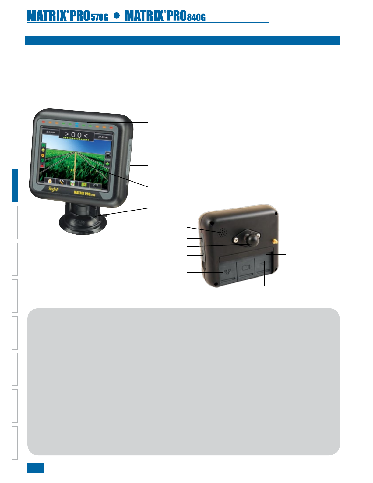
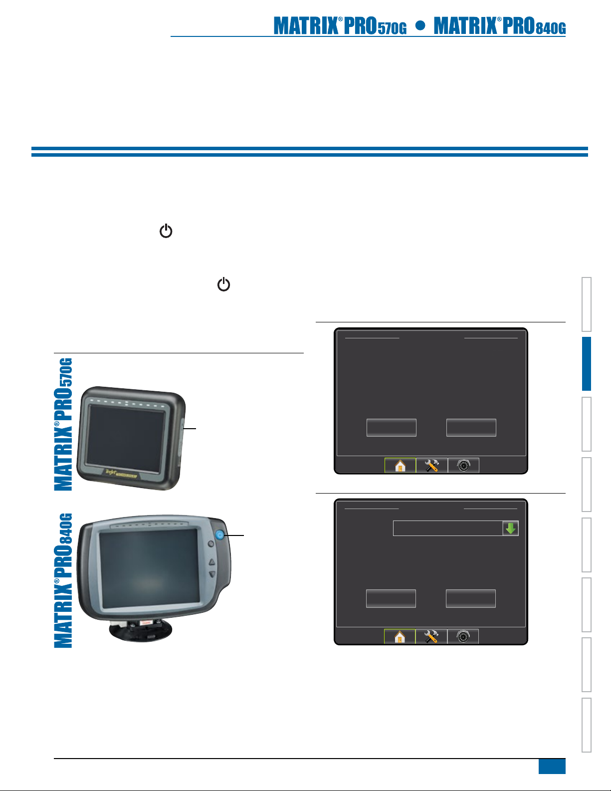
Matrix Pro 570G Console
The Matrix Pro 570G is designed to provide years of service under typical agricultural operating conditions. A tight tting enclosure, combined
with rubber covers for all connectors mean that typical dusty environments will not cause operational problems. While occasional splashing of
water will not damage the unit, the Matrix Pro 570G is not designed for direct exposure to rain. Take care not to operate the Matrix Pro in wet
conditions.
Figure 1-1: Matrix Pro 570G Console Front and Back
Built In Lightbar
Power Button
USB Port with Rubber Cover
Bright Touch Screen
Standard RAM Bracket
HOMEOVERVIEW SETUP POWER APPENDIXFULL SCREENINTRODUCTION GUIDANCE
Speaker
Power Button
Integrated RAM Mount
USB Port with Rubber Cover
Recessed Connectors
Additional Information
All changes are saved automatically.
The console needs to be cycled off and back on when changing
or attaching equipment to the Matrix Pro system.
Cleaning suggestions – Matrix consoles should be cleaned with
mild cleaners, such as glass cleaner, and a soft cloth. Take care
not to rub dust or other abrasive materials into the touch screen
surface.
• Use a soft lint-free cloth.
• The cloth may be used dry, or lightly dampened with a mild
cleaner or Ethanol.
• Be sure the cloth is only lightly dampened, not wet. Never
apply cleaner directly to touch panel surface; if cleaner
is spilled onto touch panel, soak it up immediately with
absorbent cloth.
GPS Antenna Connection
Rubber Connector Covers
Speed Signal Connection
Camera Connection
Power Connection
• Cleaner must be neither acid nor alkali (neutral pH).
• Wipe the surface gently; if there is a directional surface
texture, wipe in the same direction as the texture.
• Never use acidic or alkaline cleaners, or organic chemicals
such as: paint thinner, acetone, tolulene, xylene, propyl or
isopropyl alchohol, or kerosene.
• Suitable cleaning products are commercially available prepackaged for use; one example of such a product is Klear
Screen™, or commercially available off-the-shelf retail
brands such as Glass Plus® Glass and Surface Cleaner
made by Reckitt-Benckiser.
• Use of incorrect cleaners can result in optical impairment
of touch panel and/or damage to functionality.
2
www.teejet.com
Page 10
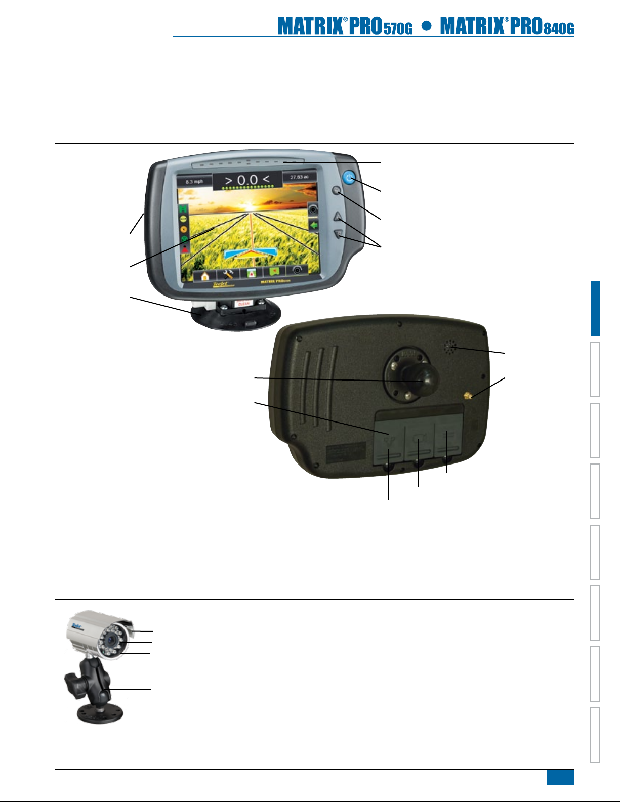
Matrix Pro 840G Console
The Matrix Pro 840G is designed to provide years of service under typical agricultural operating conditions. A tight tting enclosure, combined
with rubber covers for all connectors mean that typical dusty environments will not cause operational problems. While occasional splashing of
water will not damage the unit, the Matrix Pro 840G is not designed for direct exposure to rain. Take care not to operate the Matrix Pro in wet
conditions.
Figure 1-2: Matrix Pro 840G Console Front and Back
Built In Lightbar
Power Button
Home Button
USB Port
with Rubber Cover
Bright Touch Screen
Standard RAM Bracket
Zoom In/Out Buttons
Speaker
Integrated RAM Mount
Rubber Connector
Covers
Speed Signal Connection
Camera Connection
Power Connection
GPS Antenna
Connection
RealView Camera
The TeeJet Technologies RealView camera allows video images to be displayed on the Matrix Pro screen. The camera can be pointed
forward to enable RealView guidance over video, or it can be positioned to view other operational aspects of your equipment. The camera
is equipped with a exible RAM mount, integral sun shade and provides infrared illumination, allowing clear video images even in dark
conditions.
Figure 1-3: RealView Camera
Sun Shade
Video Camera
Nighttime Illumination
HOME OVERVIEWSETUP POWERAPPENDIX FULL SCREEN INTRODUCTIONGUIDANCE
Mounting Bracket
Matrix Pro console connection is compatible with AgCam cameras.
98-05238 R1 EN-US
3
Page 11
Optional Accessories
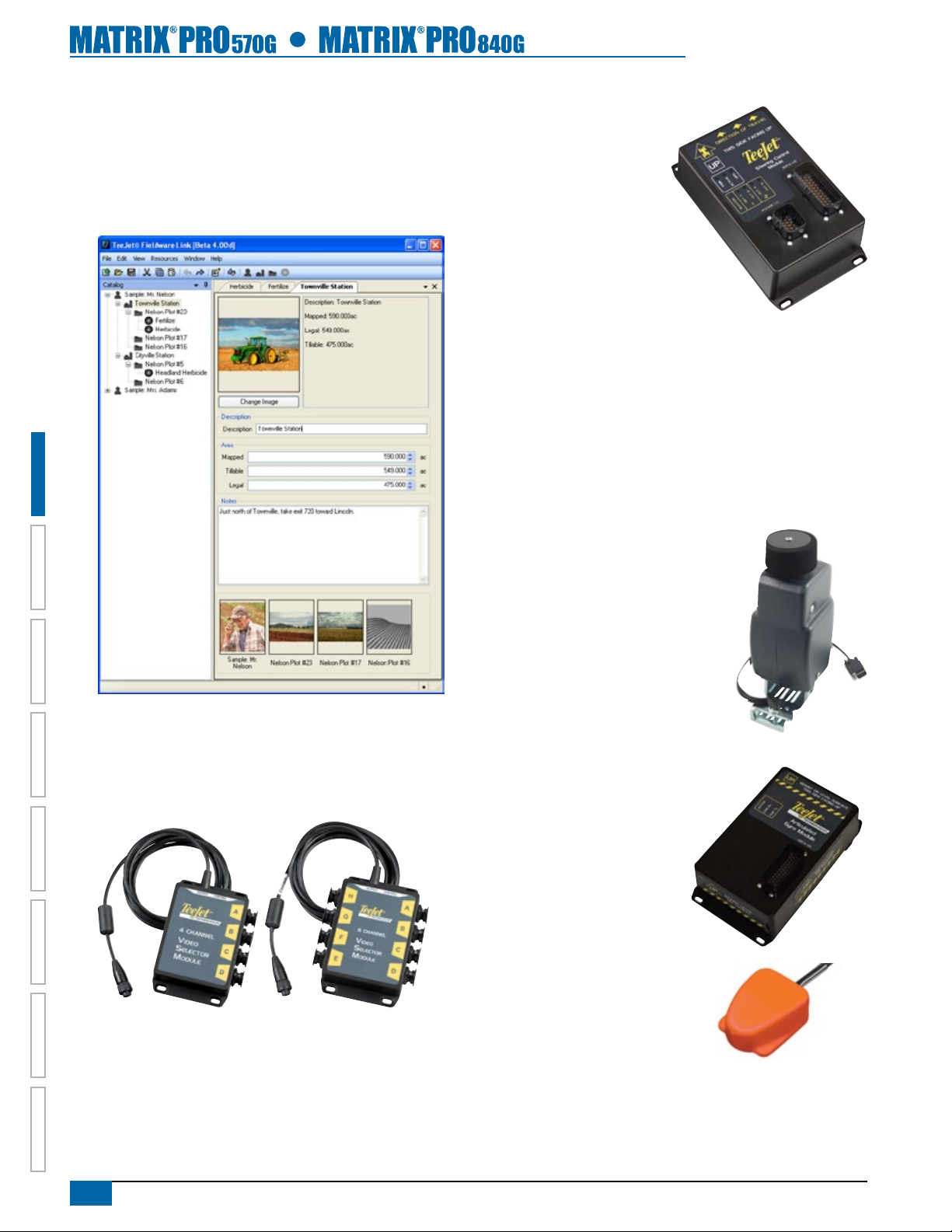
Fieldware Link
Catalog clients, farms, elds and jobs with Fieldware Link to take
full advantage of the Matrix Pro console. Duplicate and edit jobs
for reuse of boundaries and guidelines. Download this Matrix Pro
software for free at www.teejet.com.
Video Selector Modules
HOMEOVERVIEW SETUP POWER APPENDIXFULL SCREENINTRODUCTION GUIDANCE
A Video Selector Module (VSM) allows connection of up to 8 video
cameras to your Matrix console. The module is compact and robust,
and can be mounted in any convenient location. No interaction is
required after installation.
Steering Control Module
The Steering Control Module
performs assisted/auto steering
on straight and contour paths.
The Matrix Pro system can link
with the FieldPilot or UniPilot
system to take precise control of
the vehicle position. The operator
manages the assisted/automatic steering
system with the Matrix Pro – a benet of a
single, in-cab console.
FieldPilot
FieldPilot automatic steering drives a vehicle with tremendous,
repeatable accuracy in both straight and curved patterns by tapping
directly into the vehicles hydraulic steering system. The ability to
operate in fog or dust, day or night with high levels of accuracy
means a better return on capital investment for equipment, a more
effective application and more attentive, alert operation.
UniPilot
UniPilot assisted steering drives a vehicle
with tremendous, repeatable accuracy
in both straight and curved patterns by
controlling the steering wheel. The ability
to operate in fog or dust, day or night with
high levels of accuracy means a better
return on capital investment for equipment,
a more effective application and more
attentive, alert operation.
Articulated Gyro Module
Combined with the Steering Control Module,
the Articulated Gyro Module makes
assiste/auto steering on an articulated
tractor even better.
Foot Switch
TeeJet Foot Switch is a convenient
method of engaging assisted/auto
steering. It is connected to the system
via the SCM Harness.
4
www.teejet.com
Page 12
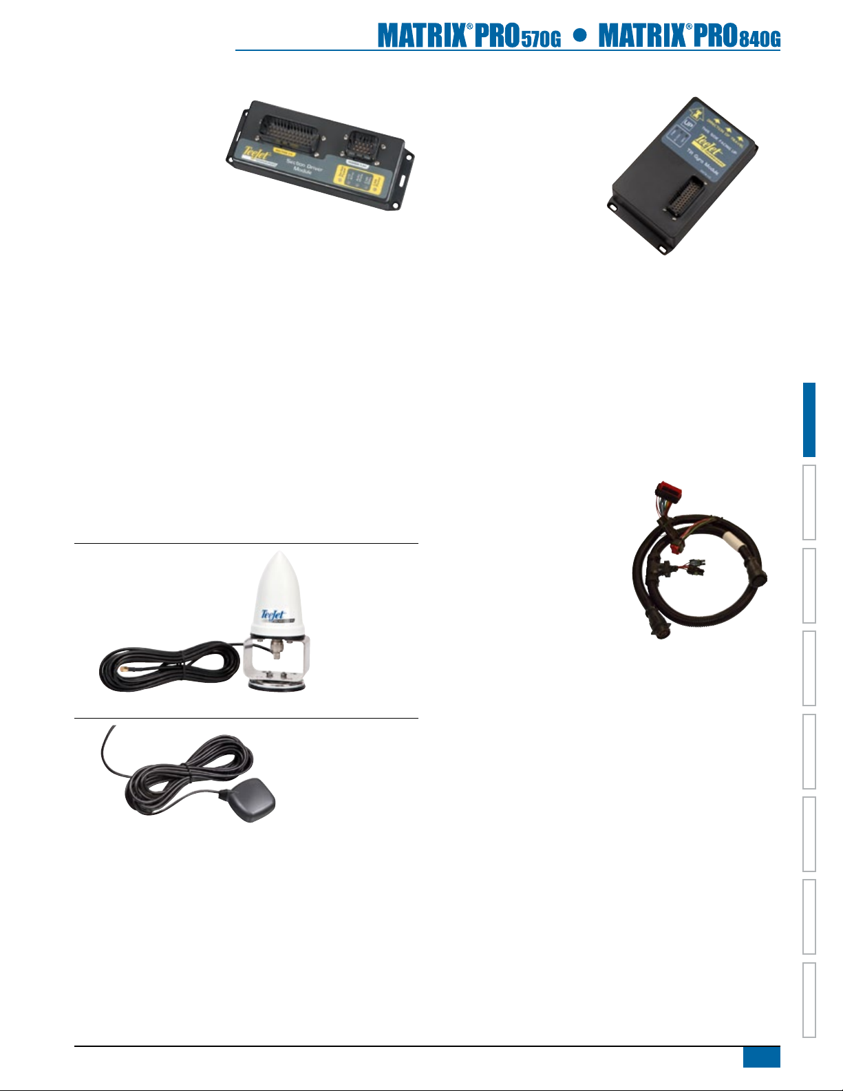
Section Driver Module
Combined with software
built into the Matrix Pro
console, the Section Driver
Module (SDM) makes
BoomPilot (automatic boom
section control) possible. The SDM
should be combined with the appropriate cable
to interface with your BoomPilot system, spray controller
and/or spraying machine for quick and easy installation. Section
Driver Modules and their related cables are designed to control
as many boom sections as the spray controller to which they are
connected, up to a maximum of 15 boom sections.
GPS Antennas
TeeJet offers a full range of high-quality GPS receivers to t your
precision farming needs.
RXA-30 GPS antenna provides a higher quality GPS receiver
that can improve GPS performance in areas of sub-optimal GPS
reception.
Tilt Gyro Module
If your GPS antenna is mounted 12 feet /
3.6 meters above the ground, a
10% side slope can cause 2 feet /
0.6 meter of position error. The
TeeJet Tilt Gyro (Compensation)
Module corrects GPS position
errors caused by side slope
conditions. Mounted on a solid
structure on your vehicle, the Tilt
Gyro (Compensation) Module sends tilt corrections to complement
GPS signals from your receiver and provide corrected position data
to your guidance device.
• Diagnostic LEDs indicate status of TGM
• Weatherproof electrical connector for trouble-free operation
• Mounting holes built into housing
• Compatible with Matrix guidance systems
NOTE: If using FieldPilot or UniPilot, a TGM is already built into the
system.
The Patch Antenna provides strong performance in standard
operating conditions. The small size of the patch antenna makes it
easy to mount and unlikely to be damaged.
Figure 1-4: GPS RXA-30 Antenna
Figure 1-5: GPS Patch Antenna II
Harnesses
TeeJet Technologies harnesses are
designed for reliable operation in
harsh environments. Shielding and
weatherproof connections ensure that
the cables and electrical connections
are reliable and trouble free.
Cable Extensions
Cable extensions, or extended length
cables, are available for special applications. Contact your TeeJet
dealer for details if the standard cables provided with your system
are not long enough.
Extended Warranty
TeeJet Technologies offers an extended warranty for many guidance
products. However, this service is not available in all markets. Please
contact your local TeeJet Technologies dealer for details.
HOME OVERVIEWSETUP POWERAPPENDIX FULL SCREEN INTRODUCTIONGUIDANCE
98-05238 R1 EN-US
5
Page 13
CONFIGURATIONS
Matrix Pro 840G
45-05765
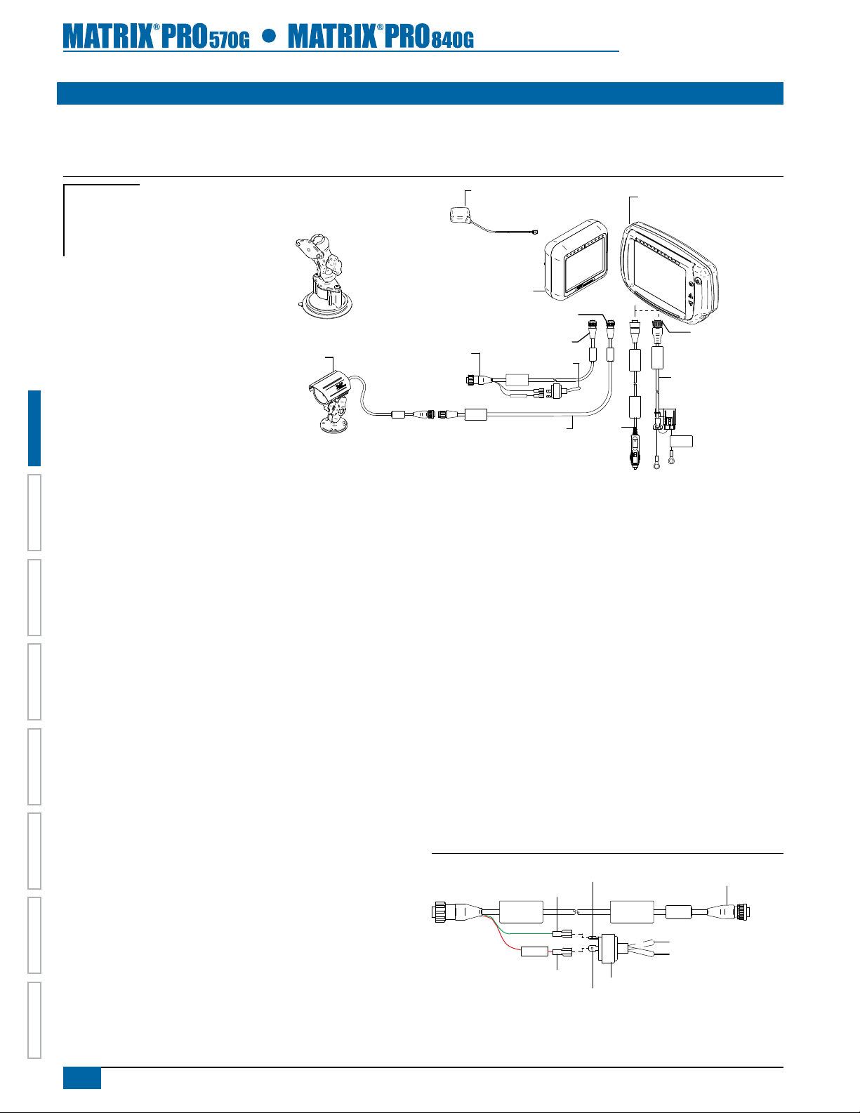
The following diagrams are reective of typical Matrix Pro congurations. Due to the variety of possible congurations, these should be used
for reference purposes only.
Figure 1-6: Matrix Pro w/RealView Camera
Matrix
FieldPilot
BoomPilot
Optional Accessory
Kit, RAM Mount w/Suction Cup
90-02349 (Matrix 570G)
90-02700 (Matrix 840G)
16-00022: RealView Camera
Speed/Sense Cable
45-05765
GPS Antenna
78-50155
78-50190 w/GLONASS
Matrix Pro 570G
75-30082
75-30083 w/GLONASS
32-50008 Switch
Speed Cable
+12V
Camera
45-05617: 20'/6m
45-05618: 60'/18m
Camera Extension Cable
5 Pos.
8 Pos.
45-05645
Power
Cable, 12V
75-30084
75-30090 w/GLONASS
8 Pos.
POWER CABLE
DC: XXXX
45-05775
Power C able
45-05775
10'/3m Power
Conn e ct to
+12v On ly
Cable, Battery
CAUTION CONN.
TO +12V ONLY
Speed Out / Sense In Cable
The Speed Out / Sense In Cable assists the Matrix Pro with two
additional connections that:
►Send a radar speed signal to an external device
►Allow the user to operate the area applied function of the Matrix
Pro in series with a remote master connection or existing apply
on/off toggle in a single swath manner. However, if the previous
connections are not available, the supplied toggle switch will allow
area applied functionality without the need to connect to a functional
HOMEOVERVIEW SETUP POWER APPENDIXFULL SCREENINTRODUCTION GUIDANCE
application implement.
Connecting to different consoles requires different adapters and
calibrations.
• If connecting to TeeJet consoles, please use speed adapter
45-20042
◄enter calibration # 914 (#1000 in Europe) for 8xx series in
RAD mode
◄enter calibration # 9140 (#10000 in Europe) for below LH 70
Series, LH 85, 500 series, 5000, 6000, IC 18, IC 24 and IC 34
• If connecting to Mid-Tech consoles no adapter is required
◄enter calibration # 1000
• If connecting to Raven consoles use speed adapter 45-05508
(do not connect the 12v red wire from 45-05508)
◄enter calibration # 800
Speed Out / Sense In Cable Is Required To Start
Application Mapping.
The Speed Out / Sense In Cable allows the user to operate the area
applied function of the Matrix Pro in series with a remote master
connection or existing apply on/off toggle in a single swath manner.
However, if the previous connections are not available, the supplied
toggle switch will allow area applied functionality without the need to
connect to a functional application implement.
The cable also sends a radar speed signal to an external device.
To install your cable:
• Connect using included switch (32-50008)
OR
• Connect green wire to master 12 Volts on/off from rate controller,
foot switch or implement status switch
If sensing boom shut-off for applied mapping from an existing
console, attach the green wire to the valve side of the master switch
on the console. The red wire is not used.
Figure 1-7: Speed Out / Sense In cable
Connect Green Wire
Green Wire Sense
Speed/
Status
Radar
Speed
Out
+12v
Red Wire (+12v)
Connect Red Wire
Speed Cable
45-05615
32-50008 Switch, Master
Speed/Sense Cable
ON
OFF
6
www.teejet.com
Page 14
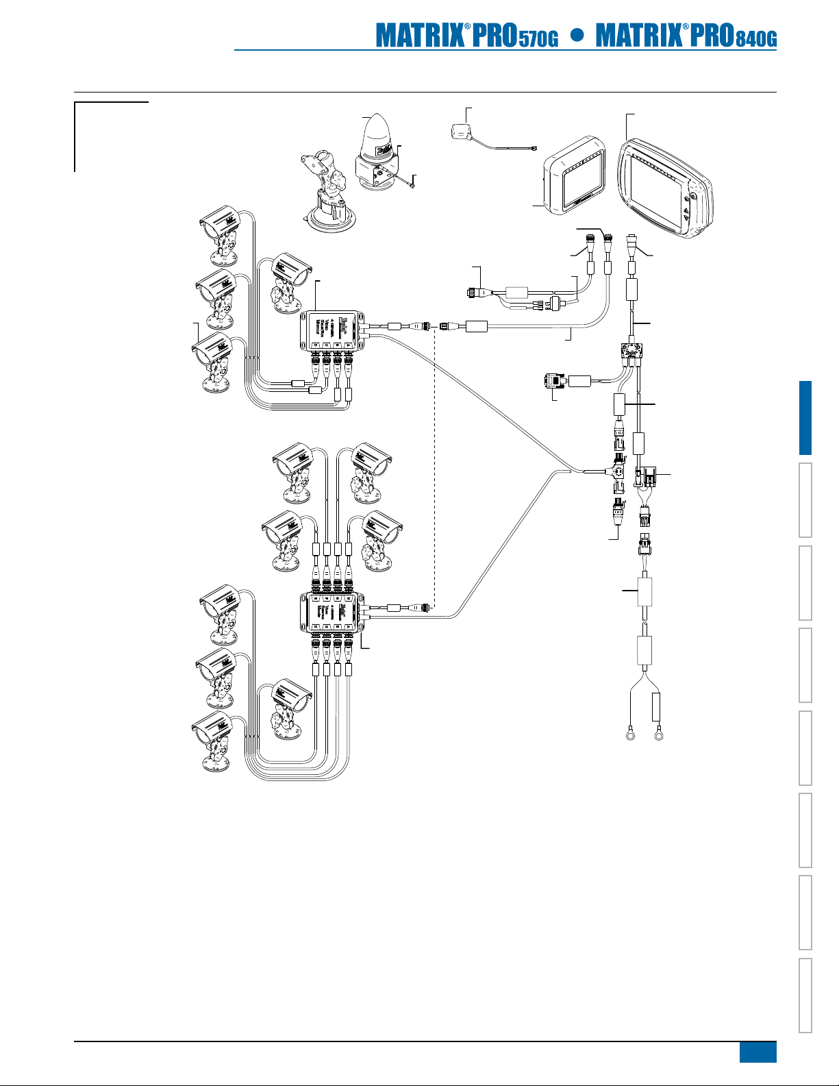
Figure 1-8: Matrix Pro w/8 Channel or 4 Channel VSM & Multiple RealView Cameras
Matrix Pro 840G
Matrix
FieldPilot
BoomPilot
Optional Accessory
Optional RXA-30
Kit, RAM Mount w/Suction Cup
90-02349 (Matrix 570G)
90-02700 (Matrix 840G)
78-50187
GPS Antenna
65-05226
Kit, Bracket
RXA-30 Antenna
45-05786: 20'/6m
45-05787: 30'/9m
Antenna Cable
GPS Antenna
78-50155
78-50190 w/GLONASS
Matrix Pro 570G
75-30083 w/GLONASS
75-30082
75-30084
75-30090 w/GLONASS
5 Pos.
16-00022
RealView Camera
78-08067
Module, 4 Channel
Video CAN
78-08068
Video Selector
Module,
8 Channel Video CAN
Speed/Sense Cable
45-05765
8 Pos.
32-50008 Switch
Speed Cable
+12V
Camera
45-05617: 20'/6m
45-05618: 60'/18m
Camera Extension Cable
CAN Terminator
RS-232
RS-232
45-08101
401-0016
Battery Adapter
Power/DATA
45-05626
CAN
POWER IN
DC: xx/xx
8 Pos.
45-05626
Power/CAN/Data
Cable
(included with
FieldPilot and
BoomPilot kits)
TJ CAN
(Terminated)
10A Fuse
Power Cable
401-0016
WARNING CONNECT
DIRECTLY TO BAT.
CAUTION: CONNECT
TO 12V ONLY
HOME OVERVIEWSETUP POWERAPPENDIX FULL SCREEN INTRODUCTIONGUIDANCE
98-05238 R1 EN-US
7
Page 15
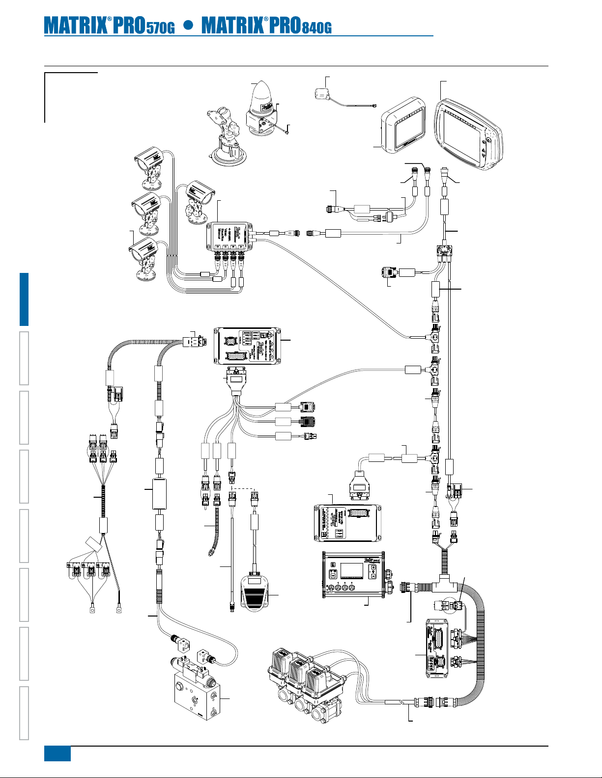
Figure 1-9: Matrix Pro w/VSM & Multiple RealView Cameras, FieldPilot and BoomPilot
Console Harness
Matrix Pro 840G
Matrix
FieldPilot
BoomPilot
Optional Accessory
Optional RXA-30
Kit, RAM Mount w/Suction Cup
90-02349 (Matrix 570G)
90-02700 (Matrix 840G)
78-50187
GPS Antenna
65-05226
Kit, Bracket
RXA-30 Antenna
45-05786: 20'/6m
45-05787: 30'/9m
Antenna Cable
GPS Antenna
78-50155
78-50190 w/GLONASS
Matrix Pro 570G
75-30083 w/GLONASS
75-30082
75-30084
75-30090 w/GLONASS
5 Pos.
RealView Camera
HOMEOVERVIEW SETUP POWER APPENDIXFULL SCREENINTRODUCTION GUIDANCE
45-05381
Battery
12'/3.66m
w/15Amp
Fuses
C
(
Articulated Gyro Module
(AGM) components are
only required for articulated tractors.
16-00022
45-07703 SCM Power In/Out
Power
78-08072
Voltage
Regulator
DC: xx/x x
45-0 5381
o
n
n
e
ct
+
1
o
2
t
v)
o
45-10103
Harness
Steering
(A+B)
SCM Power I/O
45-07703
DC: xx/xx
Valve Output
FieldPilot Interface
78-08072
DC: xx/xx
Steering Valve
45-10103
DC: xx/xx
45-07708
SCM Harness
Seat Sensor
91-07011
Steering
Wheel
Switch
Kit
32-04040
Remote
Engage/
Disengage
Switch
78-08067
Module, 4 Channel
Video CAN
Wheel Sense
Engage/Disengage
Steering
Remote
Steering
Valve
Speed/Sense Cable
SCM COM 2
GPS In
COM 1
GPS Power
32-04020
DC: xx/xx
Engage / Disengage
32-04020
Optional
Footswitch
Valves
45-05765
78-08075
Steering Control
Module (SCM)
78-08076
Articulated
Gyro Module
(AGM)
Rate Controller
dependent on Rate Controller
8 Pos.
32-50008 Switch
Speed Cable
+12V
Camera
45-05617: 20'/6m
45-05618: 60'/18m
Camera Extension Cable
45-08117 CAN
Extension Cable 20'/6m
45-07716
Tilt Gyro Module (TGM)
Harness
Tilt Gyro Module
CAN Harness
45-07716
DC: xx/xx
CAN Extension
Cable 20'/6m
BoomPilot Harness
Part number
78-05077
BoomPilot
Section Driver
(15 sections)
RS-232
RS-232
CAN Tee
45-08117
Module
8 Pos.
Power/DATA
45-05626
45-05626
Power/CAN/Data
Cable
(included with
FieldPilot and
BoomPilot kits)
CAN
TJ CAN
(Terminated)
CAN
POWER IN
10A Fuse
Remote ABSC
Status Switch
Connection
8
www.teejet.com
Page 16
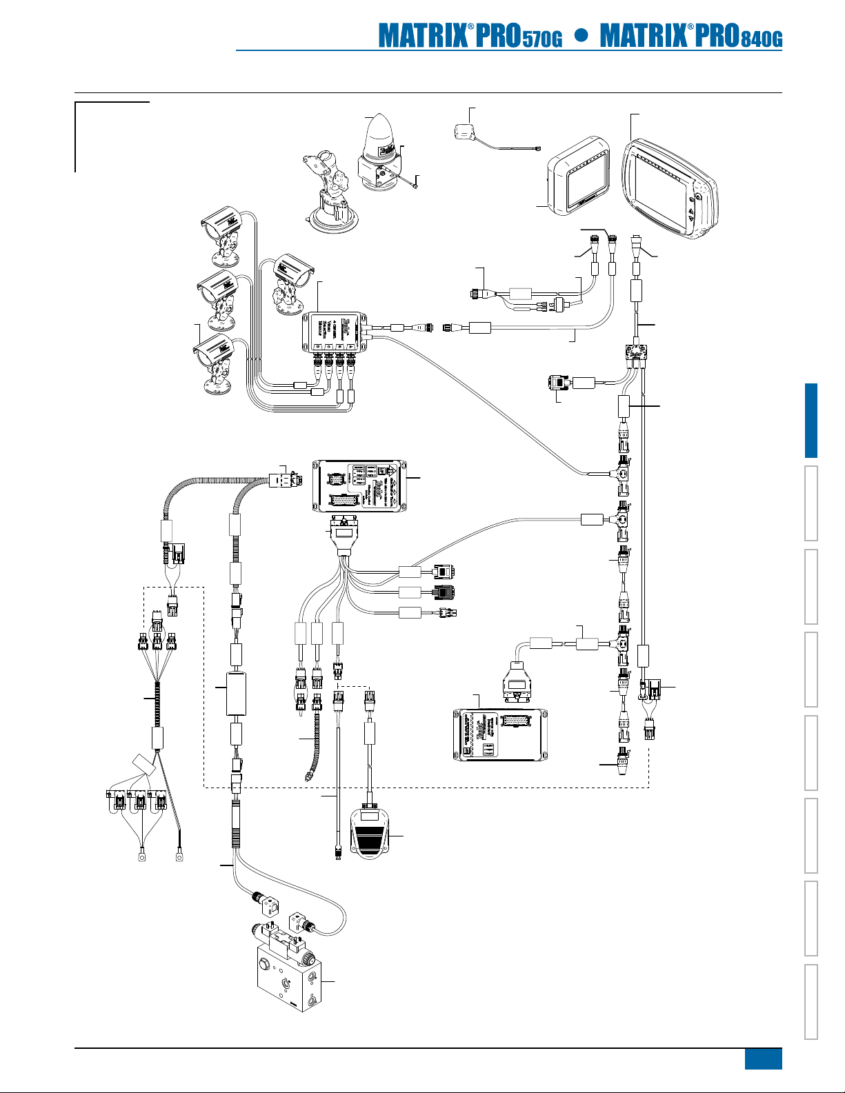
Figure 1-10: Matrix Pro w/VSM & Multiple RealView Cameras and FieldPilot
Matrix Pro 840G
Matrix
FieldPilot
BoomPilot
Optional Accessory
Kit, RAM Mount w/Suction Cup
90-02349 (Matrix 570G)
90-02700 (Matrix 840G)
78-50187
Optional RXA-30
GPS Antenna
65-05226
Kit, Bracket
RXA-30 Antenna
45-05786: 20'/6m
45-05787: 30'/9m
Antenna Cable
75-30083 w/GLONASS
GPS Antenna
78-50155
78-50190 w/GLONASS
Matrix Pro 570G
75-30082
75-30084
75-30090 w/GLONASS
5 Pos.
RealView Camera
45-05381
Battery
12'/3.66m
w/15Amp
Fuses
C
16-00022
45-07703 SCM Power In/Out
Power
78-08072
Voltage
Regulator
DC: xx/x x
45-0 5381
o
n
n
e
(
ct
+
1
o
2
t
v)
o
45-10103
Harness
Steering
(A+B)
SCM Power I/O
45-07703
DC: xx/xx
Valve Output
FieldPilot Interface
78-08072
DC: xx/xx
Steering Valve
45-10103
DC: xx/xx
45-07708
SCM Harness
91-07011
Steering
Wheel
Switch
Kit
32-04040
Remote
Engage/
Disengage
Switch
78-08067
Module, 4 Channel
Video CAN
Wheel Sense
Engage/Disengage
Seat Sensor
Steering
Speed/Sense Cable
45-05765
8 Pos.
32-50008 Switch
Speed Cable
+12V
Camera
45-05617: 20'/6m
45-05618: 60'/18m
Camera Extension Cable
RS-232
RS-232
Power/DATA
45-05626
CAN
8 Pos.
45-05626
Power/CAN/Data
Cable
(included with
FieldPilot and
BoomPilot kits)
TJ CAN
(Terminated)
78-08075
Steering Control
Module (SCM)
CAN
SCM COM 2
GPS In
COM 1
Remote
GPS Power
Tilt Gyro Module (TGM)
45-08117 CAN
Extension Cable 20'/6m
45-07716
Harness
Tilt Gyro Module
CAN Harness
45-07716
DC: xx/xx
CAN Tee
POWER IN
78-08076
Articulated
Gyro Module
(AGM)
45-08117
CAN Extension
10A Fuse
HOME OVERVIEWSETUP POWERAPPENDIX FULL SCREEN INTRODUCTIONGUIDANCE
Cable 20'/6m
32-04020
DC: xx/xx
Engage / Disengage
45-08101
CAN Terminator
32-04020
Optional
Footswitch
Articulated Gyro Module
(AGM) components are
only required for articulated tractors.
Steering
Valve
98-05238 R1 EN-US
9
Page 17
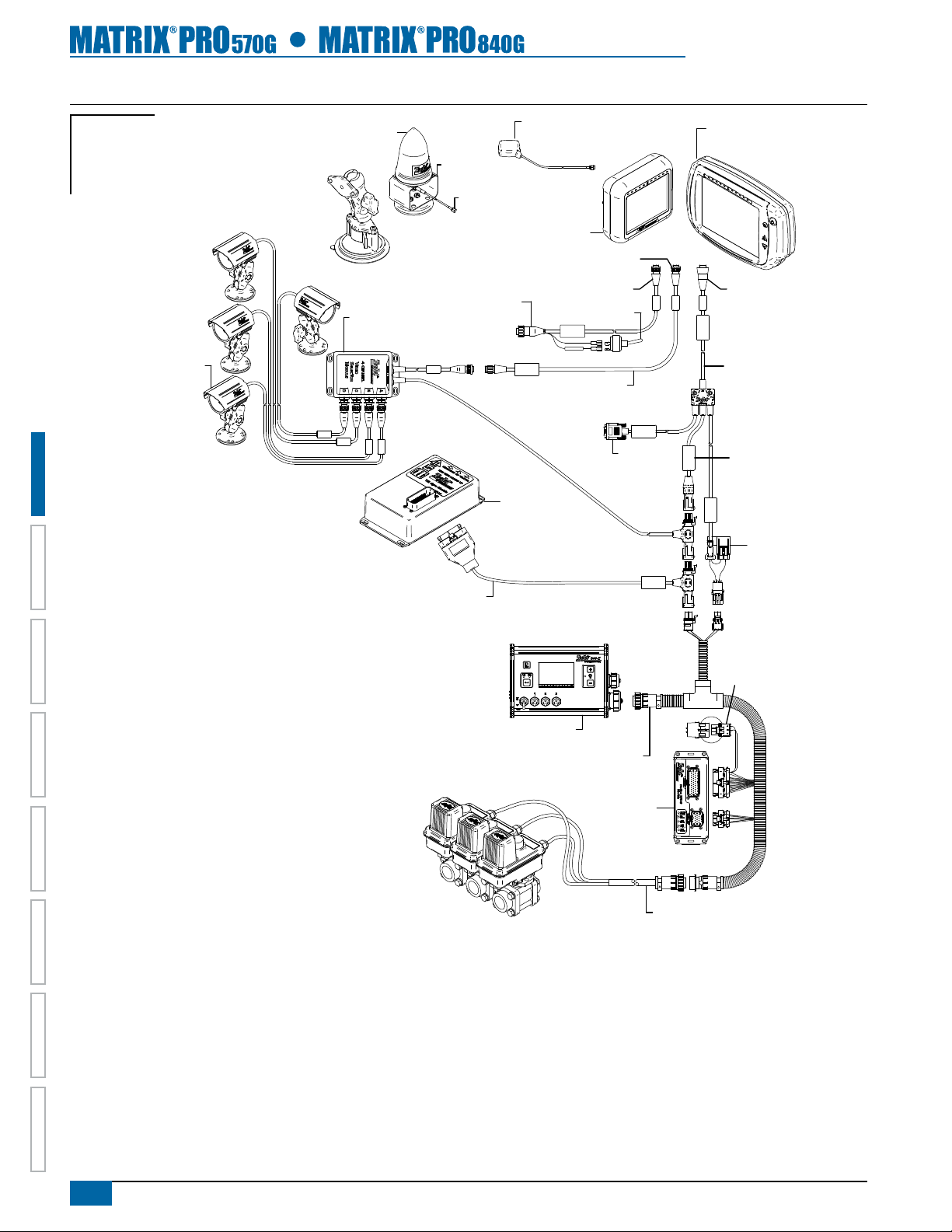
Figure 1-11: Matrix Pro w/VSM, Tilt Gyro and BoomPilot
Matrix Pro 840G
Matrix
FieldPilot
BoomPilot
78-50187
Optional RXA-30
GPS Antenna
Optional Accessory
Kit, RAM Mount w/Suction Cup
90-02349 (Matrix 570G)
90-02700 (Matrix 840G)
65-05226
Kit, Bracket
RXA-30 Antenna
45-05786: 20'/6m
45-05787: 30'/9m
Antenna Cable
75-30083 w/GLONASS
GPS Antenna
78-50155
78-50190 w/GLONASS
Matrix Pro 570G
75-30082
75-30084
75-30090 w/GLONASS
5 Pos.
HOMEOVERVIEW SETUP POWER APPENDIXFULL SCREENINTRODUCTION GUIDANCE
16-00022
RealView Camera
78-08067
Module, 4 Channel
Video CAN
TGM Harness
Speed/Sense Cable
45-05765
78-08057
Tilt Gyro
Module (TGM)
45-07716
Rate Controller
dependent on Rate Controller
8 Pos.
32-50008 Switch
Speed Cable
+12V
Camera
45-05617: 20'/6m
45-05618: 60'/18m
Camera Extension Cable
BoomPilot Harness
Part number
RS-232
RS-232
CAN
Power/DATA
45-05626
CAN
POWER IN
8 Pos.
45-05626
Power/CAN/Data
Cable
(included with
FieldPilot and
BoomPilot kits)
TJ CAN
(Terminated)
10A Fuse
Remote ABSC
Status Switch
Connection
10
www.teejet.com
Valves
78-05077
BoomPilot
Section Driver
Module
(15 sections)
Console Harness
Page 18
CHAPTER 2 POWER
Power On
Press the POWER BUTTON to power on the console.
Upon power up, the Matrix Pro will begin its Start Up Sequence.
Power O
Press and briey hold the POWER BUTTON until a conrmation
screen acknowledges shut down mode.
WARNING! Wait 30 seconds before restarting the console after
powering off.
Figure 2-1: Power Button
Power Button
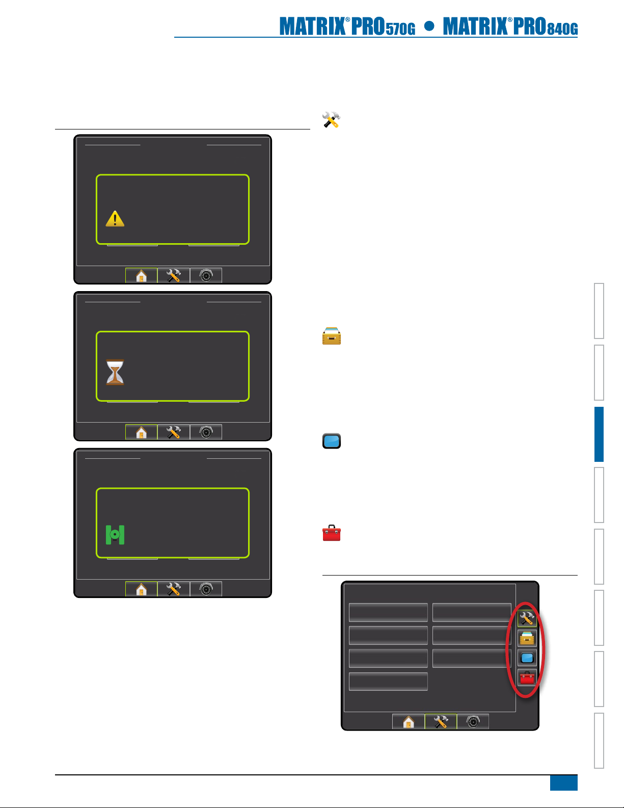
Start Up Sequence
The console takes approximately 40 seconds to power up. During
this time a series of screen including the TeeJet Technologies logo,
a globe, an hourglass and an information screen will be displayed
(LEDs will power on and off and brightness levels will uctuate.)
Once the power up sequence has completed, the Home screen will
appear.
Figure 2-2: Home Screen - Simple Mode
12/14/10 3:52 AM
Do you want to start a new job data or continue last job?
Starting a new job will clear the previous job data.
New Job
Figure 2-3: Home Screen - Advanced Mode
4/4/11 6:38 AM
Continue
HOME OVERVIEWSETUP POWERAPPENDIX FULL SCREEN INTRODUC TIONGUIDANCE
Fertilize
Power Button
Job
Client: Mr. Nelson
Farm: Townville Station
Field: Nelson Plot #23
New Job
Start Job
98-05238 R1 EN-US
11
Page 19
CHAPTER 3 INTRODUCTION
The Matrix Pro can be used as a simple current job system or advanced multi-job system. Regardless of which mode the console is in, the
basic screen functions are the same.
• Bottom Tab Keys and Side Tab Keys access the various screens and sub-screens
• Warnings and Information Pop-ups inform of console activities and details on setup or guidance functions
• Setup options can easily be set using the drop down menus or keyboard entry screens
To quickly nd a setup feature, see the Unit Setup Mode Menu Structure chart.
For full functionality of the Matrix Pro’s abilities be sure to setup the required setup options.
JOBS HOME SCREEN
Setup for the specic vehicle and its components must be completed before starting a job. Once a job is active, some setup options are not
available to be changed. See the Unit Setup Mode Menu Structure chart in the introduction chapter or setup chapter for details.
Simple Mode
In simple mode, only one job will be available at a time. Only bounded and applied area are displayed on the home screen. Only the current
job is available for saving in Reports, and use with Fieldware Link is not available.
Advanced Mode
HOMEOVERVIEW SETUP POWER APPENDIXFULL SCREENINTRODUC TION GUIDANCE
In advanced mode, more than one job will be available at any time. Client, farm, eld, job, bounded area and applied area are displayed on
the home screen. The Job name is the only information that can be entered using the console. All saved jobs can be saved in Reports. With
Fieldware Link, a user can input client, farm and eld data as well as duplicate/edit jobs for reuse of boundaries and guidelines. Client, Farm
and Field information can only be inputted using Fieldware Link.
BASIC SCREEN USE
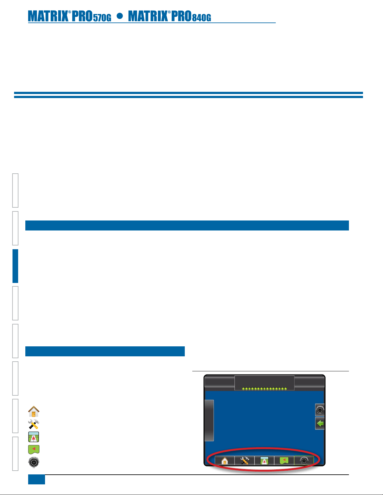
Bottom Tab Keys
The bottom tab keys are always available on screen. These keys
give access to jobs, setup options and navigation.
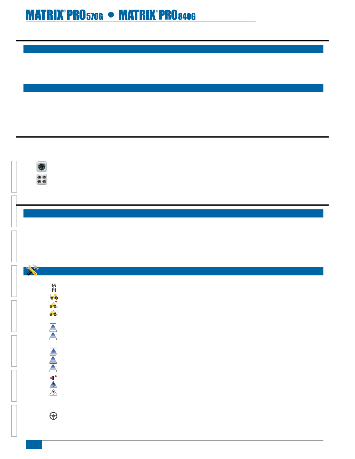
Five bottom tabs are:
Home/Job Screen
Unit Setup
Vehicle View Guidance
NOTE: RealView Guidance options are only available with a camera
installed on the system.
Figure 3-1: Bottom Tab Keys
-13 7.2 mph
> 0.0 <
Field View Guidance
RealView Guidance or
RealView Camera Full Screen Video View
12
www.teejet.com
Page 20
Warnings and Information Pop-ups
A pop-up warning or information box will be displayed for
approximately ve (5) seconds. To remove the information box, tap
anywhere on the screen.
Figure 3-2: Information Screens
12/14/10 3:52 AM
Setup Screens
Side Tab Keys in Unit Setup
Four side tabs on the Unit Setup screen access setup options for:
Vehicle/Implement Conguration
• Vehicle (Vehicle Type, Antenna Height, Direction to Boom,
Distance to Boom)
Do you want to start a new job data or continue last job?
Starting a new job will clear the previous job data.
Do you want to start a new job data or continue last job?
Starting a new job will clear the previous job data.
Overheat Protection
Dimming backlight brightness to
reduce heat. Previous backlight
brightness will be restored when unit
New Job
New Job
reaches a safe temperature.
12/14/10 3:52 AM
Loading data, please wait.
12/14/10 3:52 AM
Continue
Continue
• Implement (Number of Sections, Guidance Width, Spray Width,
Overlap, Delay On, Delay Off)
• AutoSteer (Valve Type, Frequency, Minimum Duty Cycle Left/
Right, Maximum Duty Cycle, Coarse Adjustment, Deadband,
Fine Adjustment, Lookahead, Valve Test, Valve Diagnostics,
Steering Wheel Sensor, Steering Angle Sensor)
• Tilt Conguration
• Lightbar (Brightness, Mode, LED Spacing)
• GPS (GPS Type, GPS Port, GPS Information)
• Video Conguration
Data Management
• Manage Data (delete a job or duplicate a job’s Guideline Data,
Boundary Data and/or Applied Data)
• Transfer (Delete, Import or Export Job Data)
• Reports (Save PDF, KML and/or SHP le)
• Job Mode
Console Settings
• Display (Color Scheme, Brightness, Screenshot, Calibrate)
Do you want to start a new job data or continue last job?
Starting a new job will clear the previous job data.
GPS quality changed
no GPS to DGPS
New Job
Continue
• Cultural (Units, Language, Time Zone)
• Sound (Volume)
• About System Information
Tools (Calculator, Units Converter)
NOTE: All settings are automatically saved when selected.
Figure 3-3: Side Tab Keys in Unit Setup
Conguration
Vehicle
AutoSteer
Lightbar
Video
Implement
Tilt
GPS
HOME OVERVIEWSETUP POWERAPPENDIX FULL SCREEN INTRODUCTIONGUIDANCE
98-05238 R1 EN-US
13
Page 21
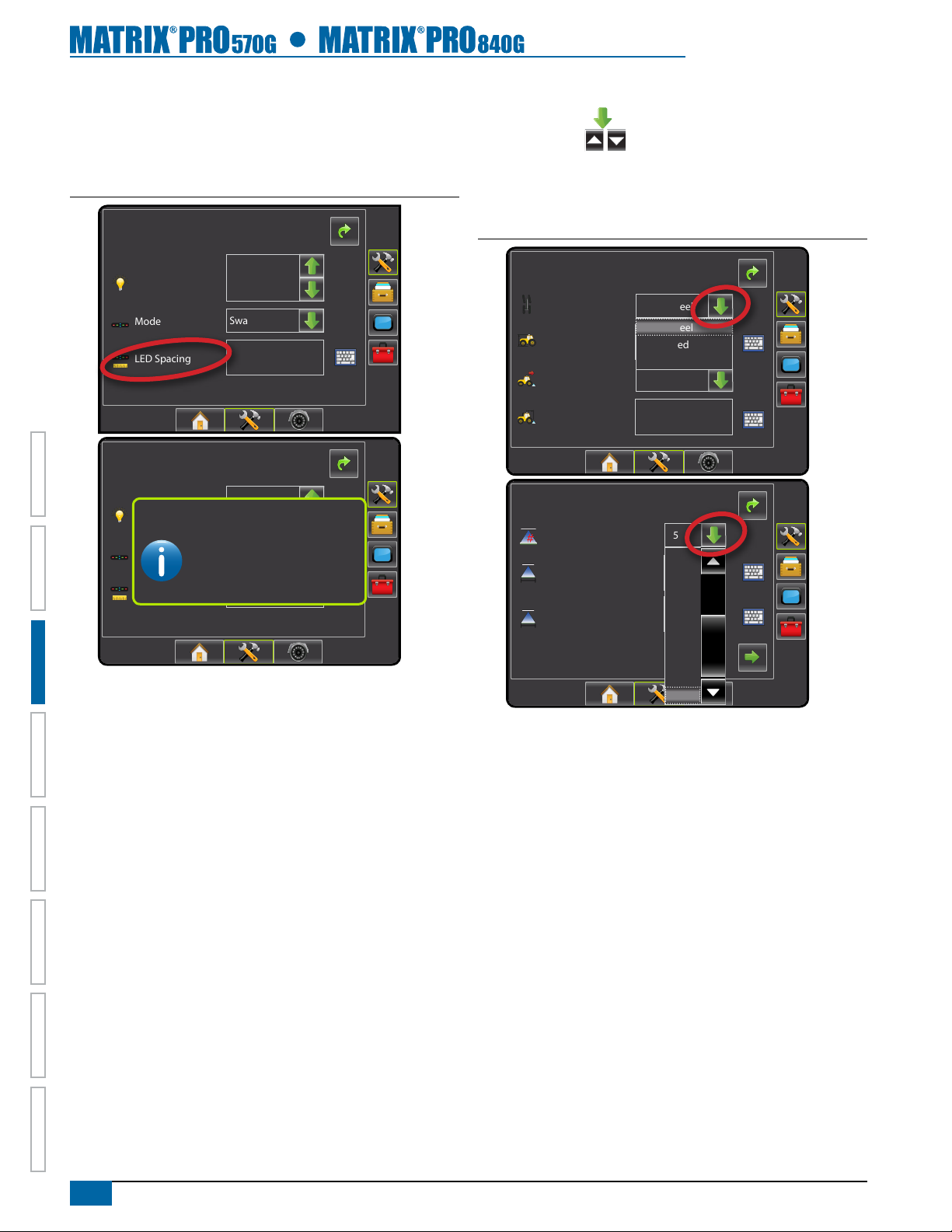
Setup Option Information
Press the option’s icon or option’s name of any menu item to display
a denition and range values of that item. To remove the information
box, press anywhere on the screen.
Figure 3-4: Example of Information Text Box
Cong-> Lightbar
Drop Down Menu Selections
Press DOWN arrow to access the list of options. Use the
UP/DOWN arrows or slide bar if necessary to scroll through
the extended list. Select the appropriate option. To close the list
without selecting an option, tap anywhere on the screen outside the
drop down menu.
Figure 3-5: Example of Drop Down Menu
Brightness
Mode
LED Spacing
Cong-> Lightbar
Brightness
Mode
LED Spacing
50%
Swath
1.50 ft
50%
LED Spacing
The distance illustrated by the
Swath
illuminated LED’s can be customized.
Input the desired spacing as required or
individual preference.
3,50 m
Cong-> Vehicle
Vehicle Type
Ant Height
Dir to Boom
Dist to Boom
Front Wheel
Front Wheel
12.50 ft
Articulated
Tracked
Backward
0.00 ft
Cong->Implement
Num Sections
Guidance Width
Spray Width
15
7
8
9
10
11
12
13
14
15
75.00 ft
75.00 ft
HOMEOVERVIEW SETUP POWER APPENDIXFULL SCREENINTRODUC TION GUIDANCE
14
www.teejet.com
Page 22
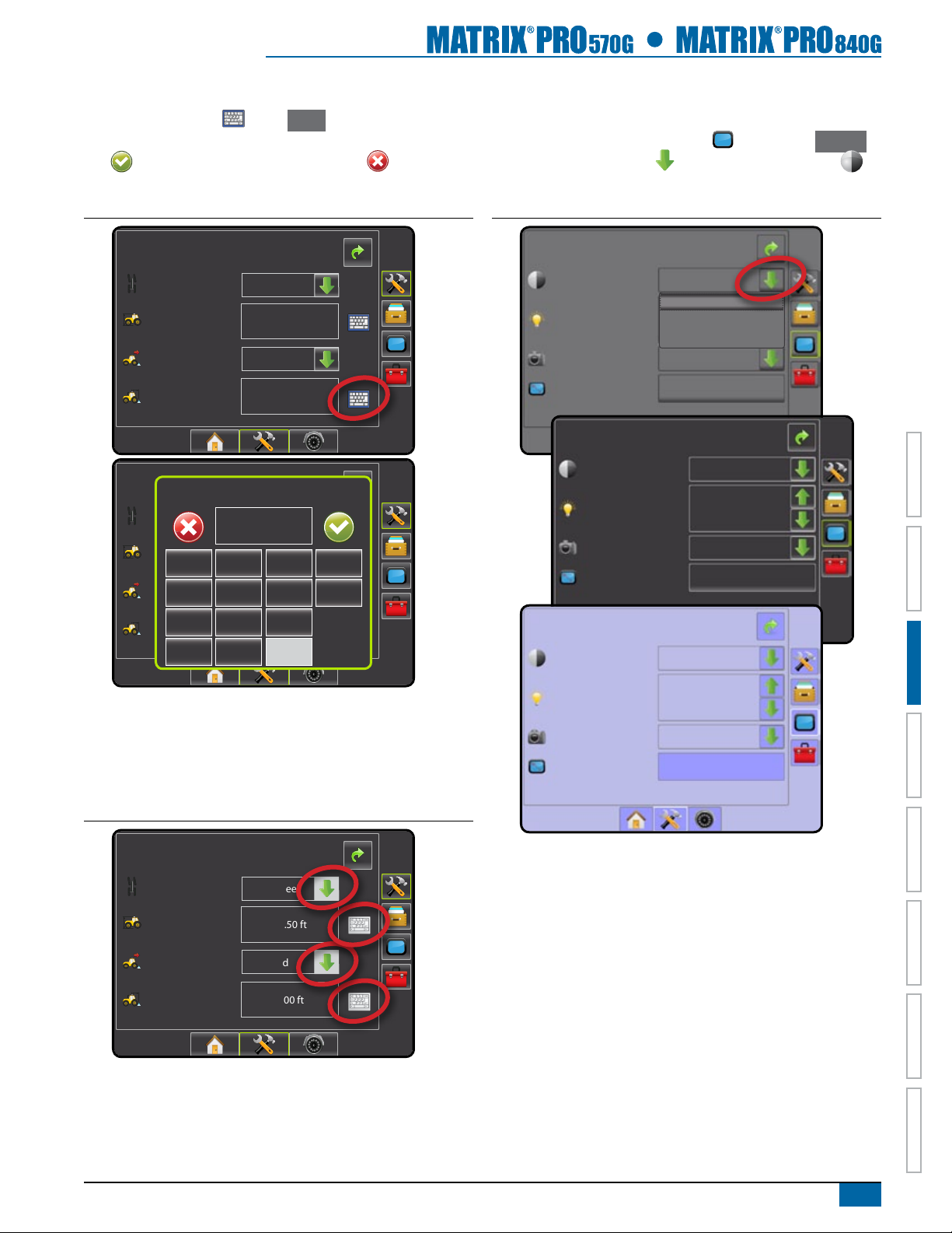
Keyboard Entry Screen
Press the KEYPAD icon . Press Clear to erase the existing
value. Use the numeric keypad to enter a value. Press the ACCEPT
icon to save the settings or the CANCEL icon to leave the
keypad without saving.
Light or Dark Console Screen
The console is available in three color schemes. From the Unit Setup
Bottom Key, press CONSOLE side tab and enter the Display
options. Press DOWN arrow to access the Color Scheme
options to select color mode.
Figure 3-6: Example of Keyboard
Cong-> Vehicle
Vehicle Type
Ant Height
Dir to Boom
Dist to Boom
Cong-> Vehicle
Front Wheel
Backward
Dist to Boom (ft)
Vehicle Type
Ant Height
1 2 3
Dir to Boom
4 5 6 <--
7 8 9
Dist to Boom
0 .
Front Wheel
0.00
Backward
12.50 ft
0.00 ft
12.50 ft
0.00 ft
+/-
Clear
Figure 3-8: Color Scheme
Console->Display
Color Scheme
Brightness
Screenshot
Calibrate
Console->Display
Style 1
Style 1
Style 2
Style 3
Enabled
Start
Colour Scheme
Brightness
Screenshot
Calibrate
Console->Display
Colour Scheme
Style 2
40%
Enabled
Start
Style 3
Unavailable Options When Job is Activate
When a job is active some setup options are unavailable. See
the Unit Setup Mode Menu Structure Chart for indication of which
options are not accessible.
Figure 3-7: Example of Unavailable Options
Cong-> Vehicle
Vehicle Type
Ant Height
Dir to Boom
Dist to Boom
Front Wheel
12.50 ft
Backward
0.00 ft
Brightness
Screenshot
Calibrate
Enabled
40%
Start
HOME OVERVIEWSETUP POWERAPPENDIX FULL SCREEN INTRODUCTIONGUIDANCE
98-05238 R1 EN-US
15
Page 23
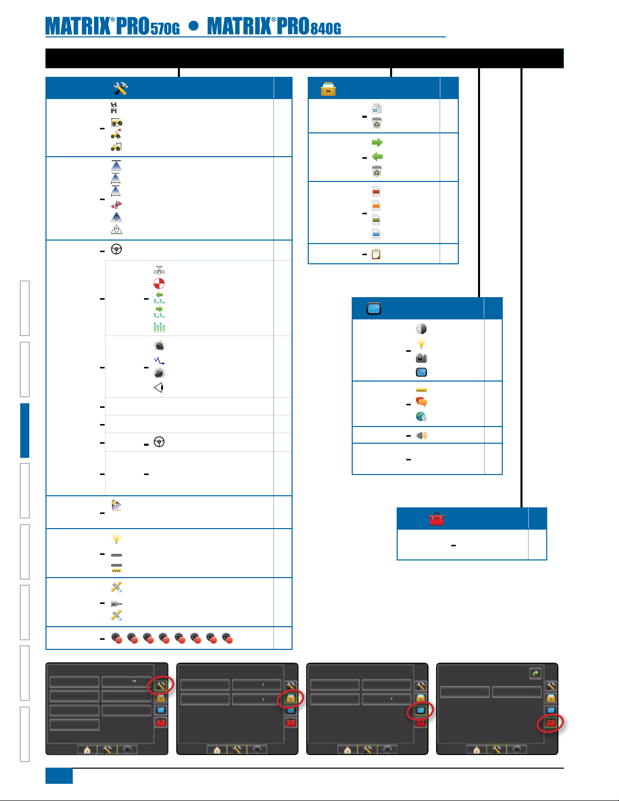
UNIT SETUP MODE MENU STRUCTURE
HOMEOVERVIEW SETUP POWER APPENDIXFULL SCREENINTRODUC TION GUIDANCE
Vehicle –
Implement –
AutoSteer
Conguration (page 35)
Vehicle Type
Antenna Height
Direction to Boom
Distance to Boom
#
Number of Sections
Guidance Width
Spray Width
Overlap
Delay On
Delay Off
–
Enable
Valve
–
Setup
Steering
–
Settings
– Valve Test
– Valve Diagnostics
Options
–
Angle
–
Sensor
–
–
–
–
Valve Type
Frequency
Minimum Duty Cycle Left
Minimum Duty Cycle Right
Maximum Duty Cycle
Coarse Adjustment
Deadband
Fine Adjustment
Lookahead
Steering Wheel Sensor
Enable
Calibrate Sensor
Offset Adjustment
Job*
Data Management (page 61)
Manage Data –
Duplicate
Delete Job Data
Job*
Transfer –
Reports –
Options –
Export Job Data
Import Job Data
Delete Job Data
PDF
Save PDF
KML
Save KML
SHP
Save SHP
ALL
Save All Types
Job Mode
Console Settings (page 70)
Display –
Cultural –
Sound –
About –
Color Scheme
Brightness
Screenshot
Calibrate
Units
Language
Time Zone
Volume
• System Information
• Save System Info
Job*
Tilt –
Lightbar –
GPS –
Video –
Conguration
Vehicle
AutoSteer
Lightbar
Video
16
www.teejet.com
Enabled
Field Level
Brightness
Mode
LED Spacing
GPS Type
GPS Port
GPS Status
B C D
A
Implement
Tilt
GPS
E
Data
F G H
Manage Data
Cameras
Transfer
OptionsOptions
Available during an active job
Not Available during an active job
Console Settings
Display
Sound
Extras –
Cultural
About
Tools (page 75)
• Calculator
• Units Converter
Tools->Extras
Calculator
Job*
Units Converter
Page 24
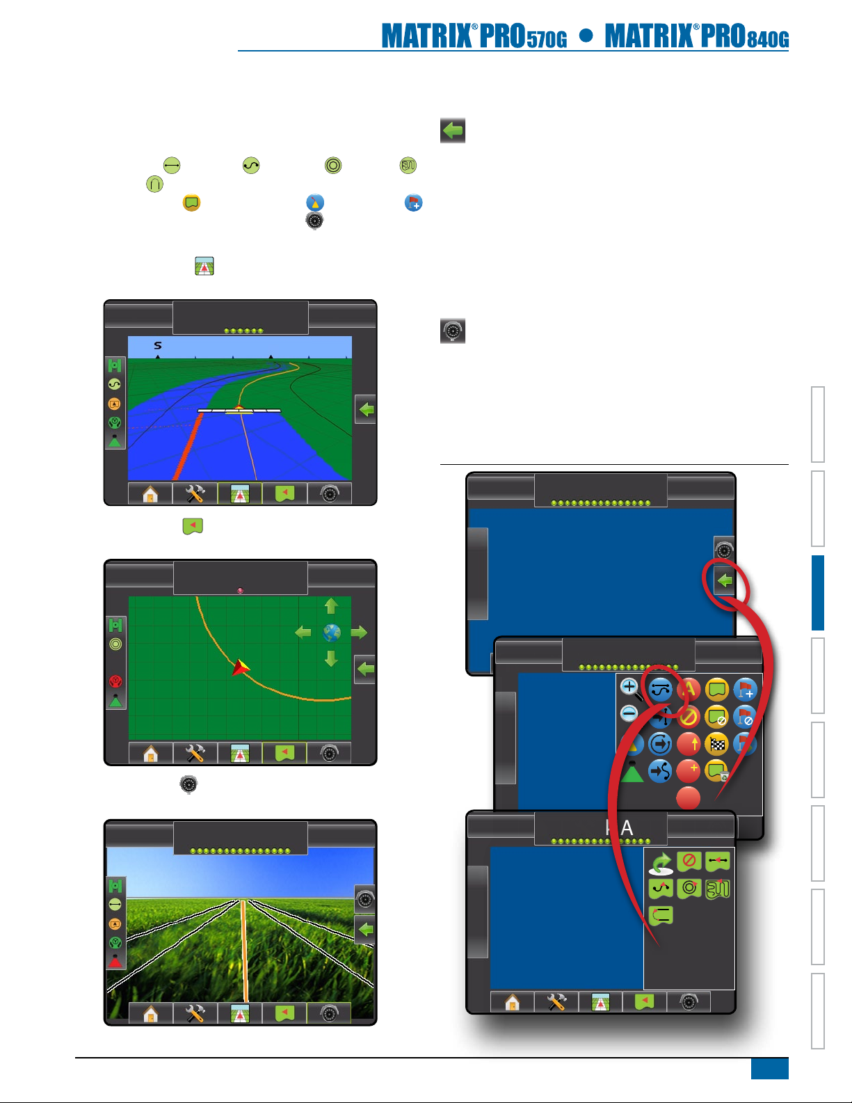
Guidance
6.0 mph 7.6 ac
< 0.0 >
6.0 mph 0 ac
Mark A
6.0 mph 0 ac
< 0.0 >
The Matrix Pro allows product application and vehicle guidance to be
performed simultaneously. Once Unit Setup is complete, guidance can
begin. Five guidance modes allow the operator to optimize the eld
work: Straight AB , Curved AB , Circle Pivot , Last Pass
and NextRow . Additional optimization can be accomplished with
Boundary Application , Curved Lookahead Return to Point
guidance and RealView Guidance Over Video . Three guidance
screens keep the user informed.
Vehicle View Guidance creates a computer-generated image of
the vehicle position displayed in the application area
Side Tab Keys in Guidance
Two side tabs on the Guidance screens access setup options for:
Navigation and Guidance Options
• Guidance mode
• Next guideline
• Mark A or mark B
• Azimuth guidance
• Create boundary
• Mark and return to point
• BoomPilot
RealView Guidance
• Single or split camera view
• Guidance over video
• Steering angle indicator
NOTE: All settings are automatically saved when selected.
Figure 3-9: Navigation and Guidance Options*
Field View Guidance creates a computer-generated image of
the vehicle position and application area from an aerial perspective.
RealView Guidance allows live video input to be displayed
instead of a computer-generated image.
-13 7.2 mph
> 0.0 <
A
A
A
B
0.0 mph 0 ac
Mark A
HOME OVERVIEWSETUP POWERAPPENDIX FULL SCREEN INTRODUCTIONGUIDANCE
* Simulated screen example to show all possibilities.
98-05238 R1 EN-US
17
Page 25
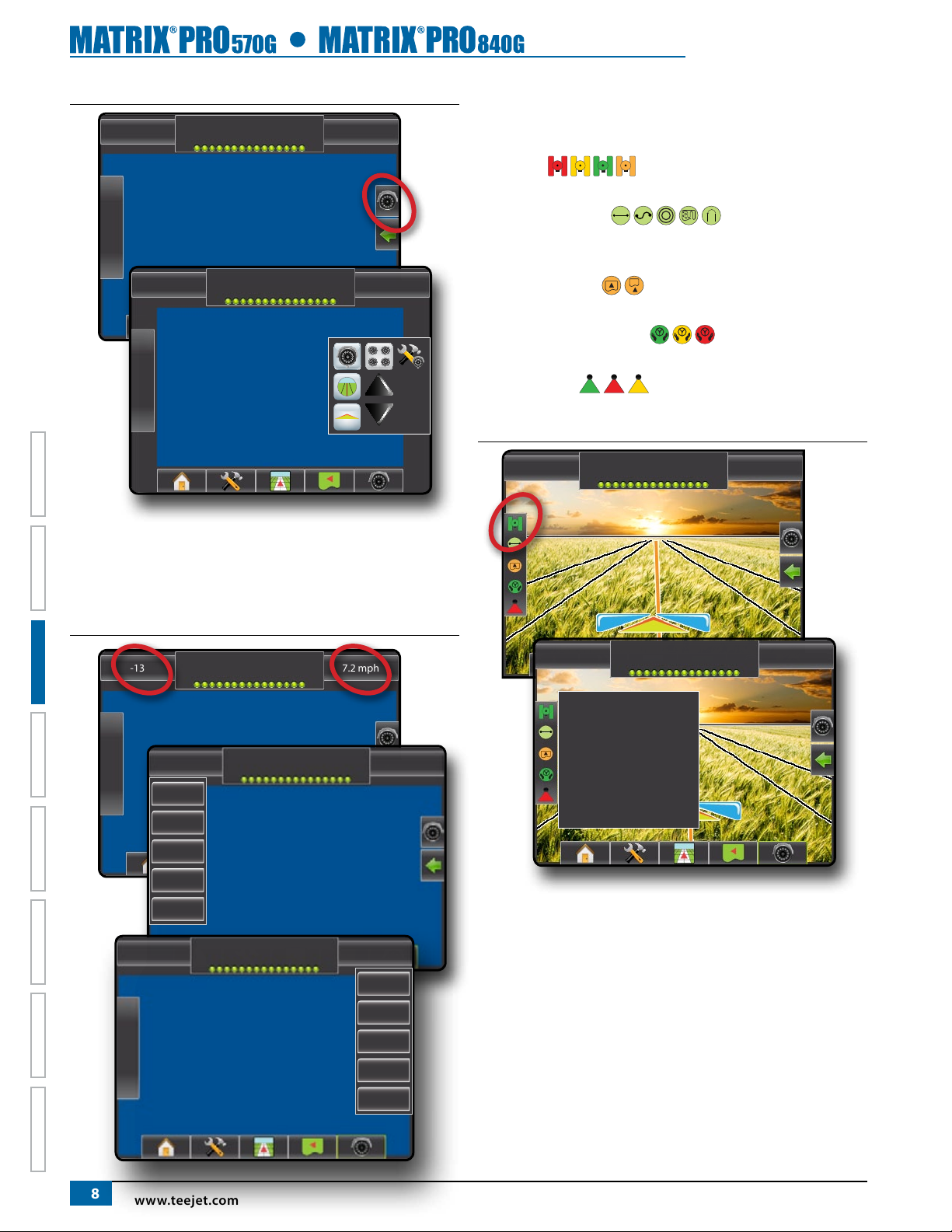
Figure 3-10: RealView Options*
-13 7.2 mph
> 0.0 <
Status/Information Screens
Status and information regarding the status bar icons can be
accessed by pressing the icon on the status bar.
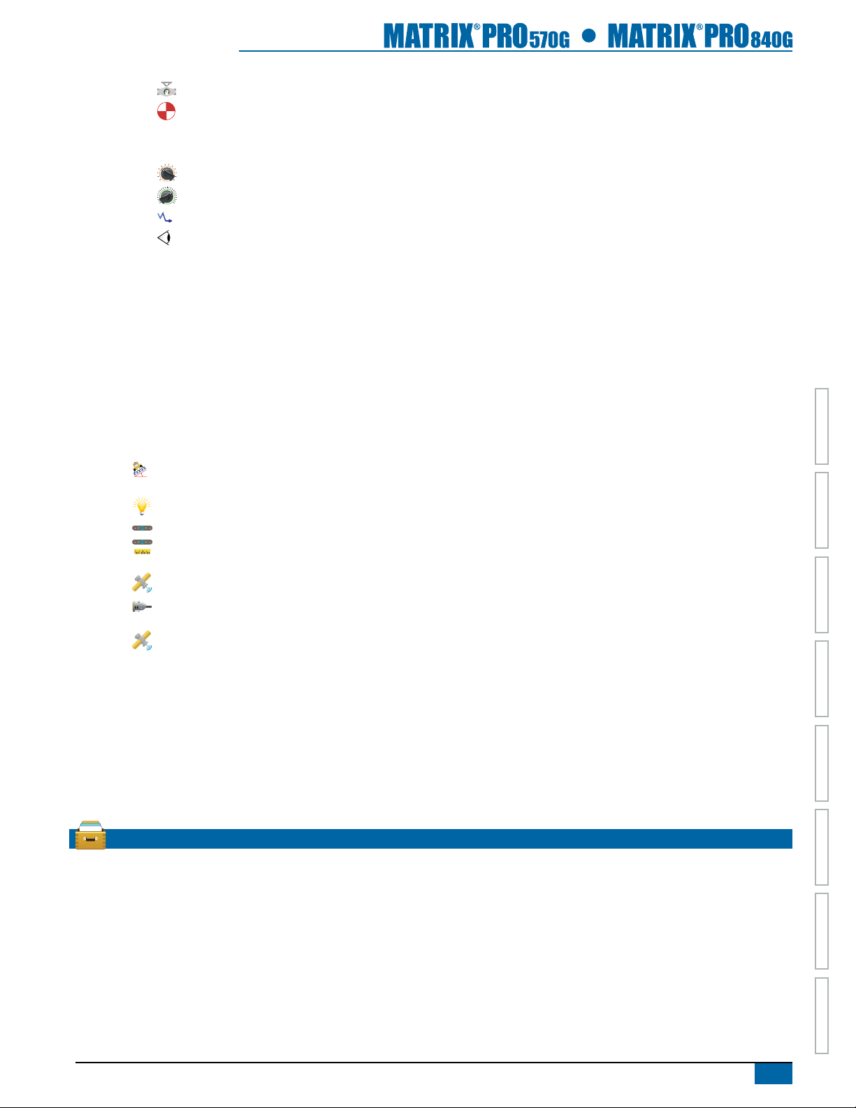
GPS Status displays information regarding data
rates, number of satellites in view, and satellite quality and ID.
Guidance Mode Status displays information
regarding the pattern of guidance, name of the current guideline and
how many guidelines are saved in the console.
Bounded Area Status displays information regarding the
areas in the current boundaries.
Assisted/Auto Steering Status displays information
regarding the current status of the auto steering system.
BoomPilot Status displays information regarding the
current status of the BoomPilot system
Figure 3-12: GPS Status
* Simulated screen example to show all possibilities.
Guidance Bar Selectable Information
Press the left or right section of the guidance bar to change the
selectable job information.
Figure 3-11: Selectable Job Information
-13 7.2 mph
HOMEOVERVIEW SETUP POWER APPENDIXFULL SCREENINTRODUC TION GUIDANCE
12:32 PM 1 deg
Speed
Area
Time
Swath #
Heading
> 0.0 <
No GPS
-13 7.2 mph
-13 7.2 mph
GGA Rate: 5 Hz
VTG Rate: 5 Hz
Num Sats: 10
HDOP: 1
PRN: 135
GGA Quality: 2
Receiver: 1
Mark A
Mark A
18
12:32 PM 1 deg
www.teejet.com
No GPS
Speed
Area
Time
Swath #
Heading
Page 26
Required- Setup Options
A series of setup options are required for guidance to properly
function. These should be setup before starting a job as they are not
available after a job has been started.
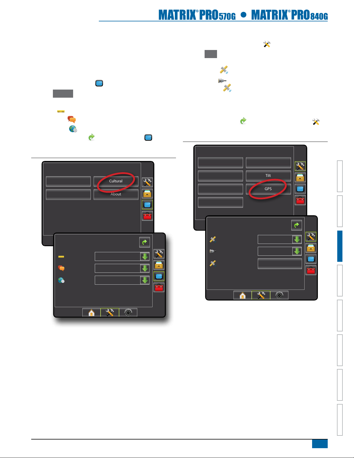
Cultural Setup
1. Press CONSOLE side tab .
2. Press Cultural .
3. Select from:
►Units – denes the system measurements
►Language – denes the system language
►Time Zone – establishes the local time zone.
4. Press RETURN arrow or CONSOLE side tab to return
to the main Console screen.
Figure 3-13: Cultural Options
Console Settings
Display
Sound
Cultural
About
GPS
1. Press CONFIGURATION side tab .
2. Press GPS .
3. Select from:
►GPS Type – select GPS source transmissions
►GPS Port – sets (D)GPS COM port
►GPS Status – displays information for TeeJet Customer
Service use on GGA/VTG (Data Rates), Number of Satellites,
HDOP, PRN, GGA Quality, GPS Receiver and Receiver
Version
4. Press RETURN arrow
return to the main Conguration screen.
Figure 3-14: GPS
Conguration
Vehicle
AutoSteer
Lightbar
Video
or CONFIGURATION side tab to
Implement
Tilt
GPS
Console->Cultural
Units US
Language
Time Zone
English-US
UTC
Cong->GPS
GPS Type
GPS Port
GPS Status
GPS/DGPS
Internal
Information
HOME OVERVIEWSETUP POWERAPPENDIX FULL SCREEN INTRODUCTIONGUIDANCE
98-05238 R1 EN-US
19
Page 27
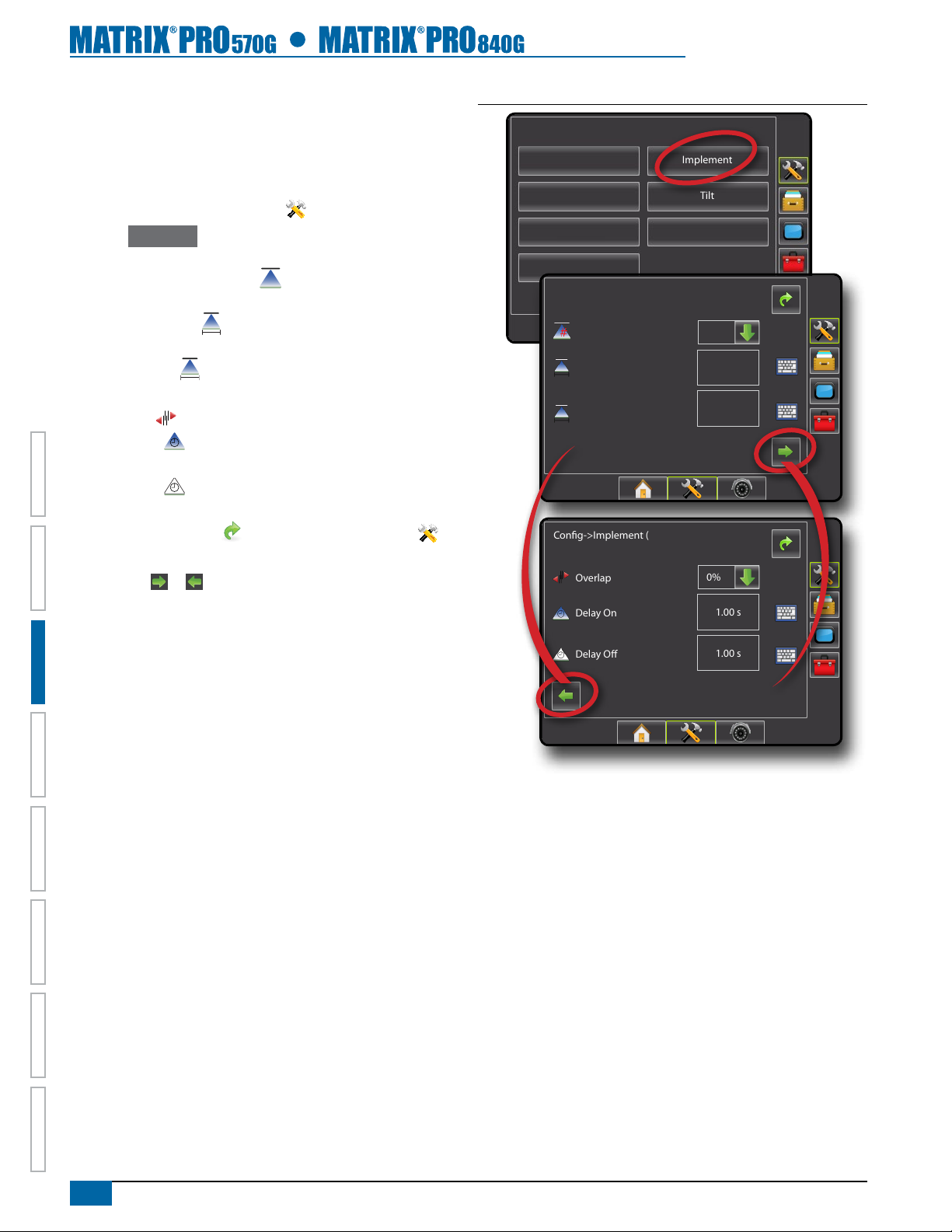
Implement Setup
When a SmartCable or Section Driver Module (SDM) is not present
only a single boom setup is available. Congurations for Overlap,
Delay On and Delay Off will not be available, and Number of
Sections will be set to one.
1. Press CONFIGURATION side tab .
2. Press
3. Select from:
4. Press RETURN arrow or CONFIGURATION side tab to
NOTE: Press or to switch between Implement setup screens.
Implement .
#
►Number of Boom Sections
– establishes the number of
boom sections
►Guidance Width – establishes the width between
guidelines
►Spray Width – establishes the width of each boom
section for a total spray width
►Overlap
►Delay On
– determines the amount of overlap allowed
– establishes the timing for the boom section
valves to switch on
►Delay Off – establishes the timing for the boom section
valves to switch off
return to the main Conguration screen.
Figure 3-15: Implement Setup Options
Conguration
Vehicle
AutoSteer
Lightbar
Video
Cong->Implement
Num Sections
Guidance Width
Spray Width
Cong->Implement (2)
Overlap
Implement
Tilt
GPS
15
60.00 ft
144.00 ft
50%
HOMEOVERVIEW SETUP POWER APPENDIXFULL SCREENINTRODUC TION GUIDANCE
Delay On
Delay O
1.00 s
1.00 s
20
www.teejet.com
Page 28
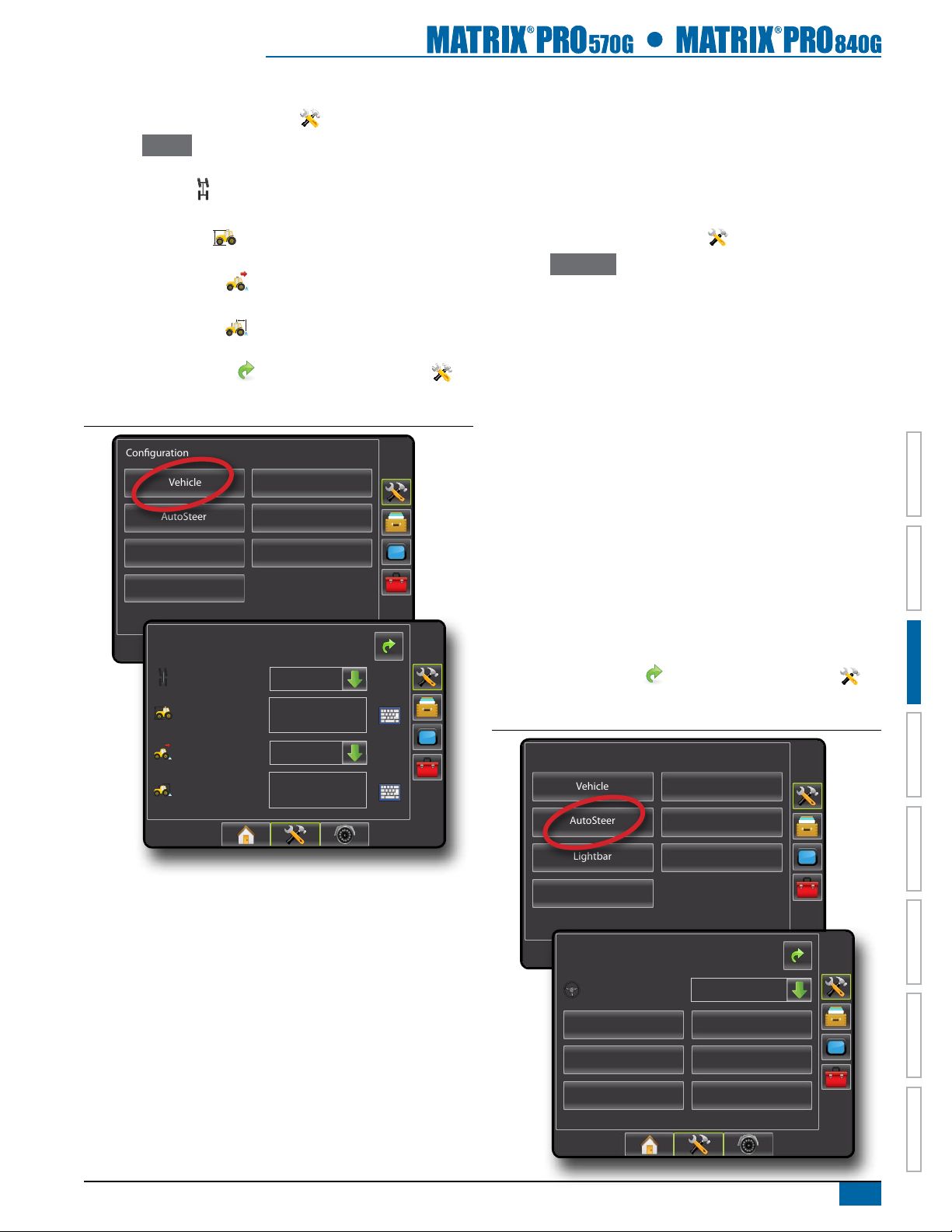
Vehicle Setup
1. Press CONFIGURATION side tab .
2. Press Vehicle .
3. Select from:
►Vehicle Type – selects the type of vehicle that most closely
represents your vehicle
►Antenna Height – sets the height of the antenna from the
ground
►Direction to Boom – sets whether the boom is located
behind or in front of the GPS antenna
►Distance to Boom
antenna to the boom
4. Press RETURN arrow
return to the main Conguration screen.
Figure 3-16: Vehicle Setup Options
Conguration
Vehicle
AutoSteer
Lightbar
Video
Cong-> Vehicle
Vehicle Type
Ant Height
– denes the distance from the GPS
or CONFIGURATION side tab to
Implement
Tilt
GPS
Front Wheel
12.50 ft
AutoSteer Setup
When a Steering Control Module (SCM) is present, Assisted/Auto
Steering options will be available. For detailed setup instructions,
refer to your specic assisted/auto steering installation manual.
NOTE: An update of your SCM software will also be required when
updating an existing Matrix console to Matrix Pro.
1. Press CONFIGURATION side tab .
2. Press
3. Select:
4. Select from:
5. Press RETURN arrow
Figure 3-17: AutoSteer
AutoSteer .
►On – enabled
►Off – disabled
►Valve Setup – used to congure Valve Type, Valve Frequency,
Minimum Duty Cycle Left, Minimum Duty Cycle Right and
Maximum Duty Cycle
►Steering Settings – used to establish Coarse Adjustment, Fine
Adjustment, Deadband and Lookahead
►Valve Test – used to verify if steering is directed correctly
►Valve Diagnostics – used to test the valves to see if they are
connected properly
►Options: Steering Wheel Sensor – used to select whether the
steering disengage sensor is magnetic or pressure based
►Angle Sensor – used to establish the Steering Angle Sensor
(SAS) as the primary feedback sensor for auto steering,
calibrate the SAS and set an offset adjustment.
or CONFIGURATION side tab to
return to the main Conguration screen.
Dir to Boom
Dist to Boom
Backward
0.00 ft
Conguration
Vehicle
AutoSteer
Lightbar
Video
Cong-> AutoSteer
Enabled
Valve Setup
Valve Test
Implement
Tilt
GPS
On
Steering Settings
Valve Diagnostics
Angle SensorOptions
98-05238 R1 EN-US
HOME OVERVIEWSETUP POWERAPPENDIX FULL SCREEN INTRODUCTIONGUIDANCE
21
Page 29
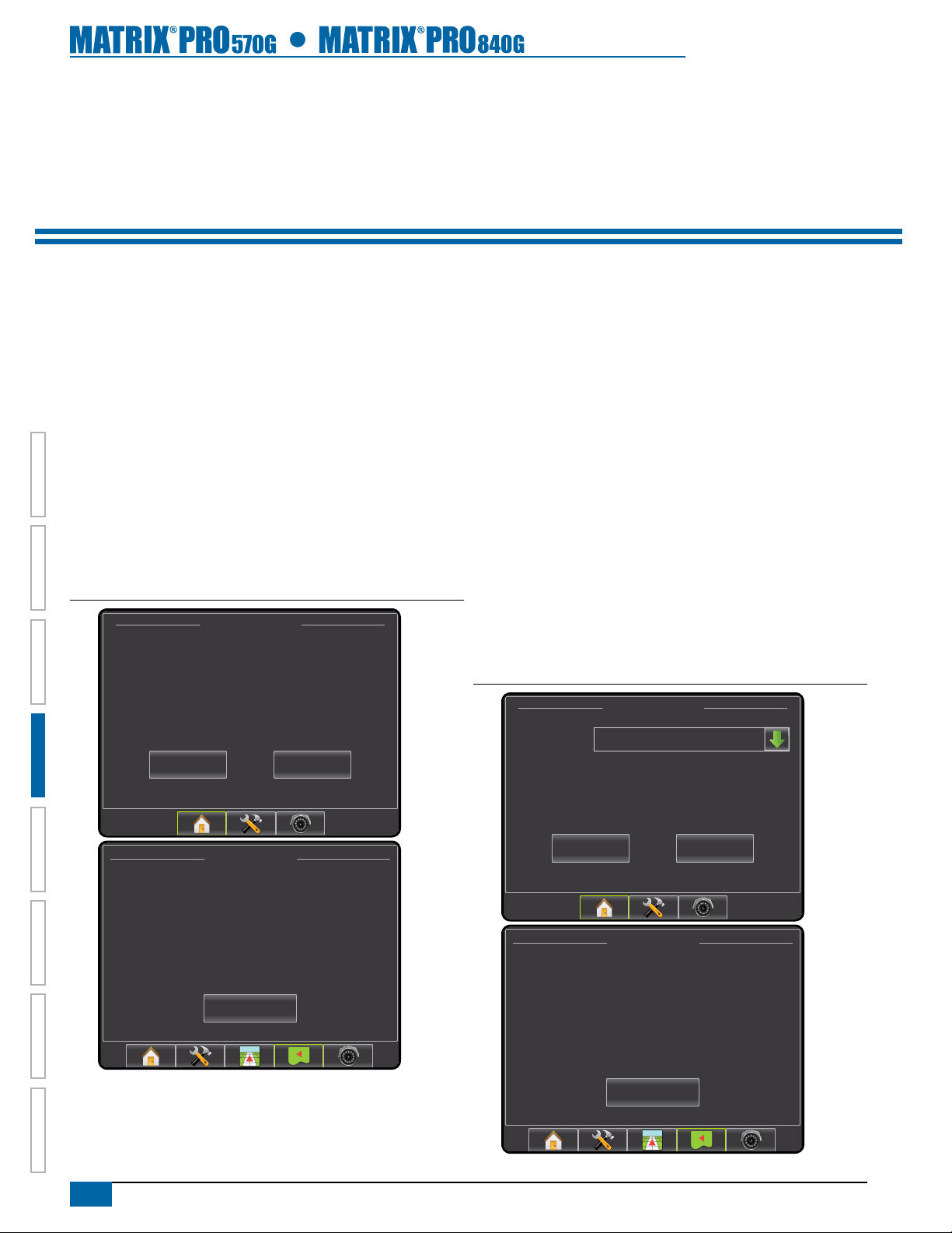
CHAPTER 4 JOBS / HOME SCREEN
Once the power up sequence has completed, the Home screen will appear with the option to start a new job or continue an existing job.
The console must have GPS before starting or continuing job.
Setup for the specic vehicle and its components must be completed before starting a job. Once a job is active, some setup
options are not available to be changed. See the Unit Setup Mode Menu Structure chart in the introduction chapter or setup chapter for details.
To change between simple mode and advanced mode, see the conguration chapter under Data Management – Options.
Simple Mode
In simple mode, only one job will be available at a time. Only bounded
and applied area are displayed on the home screen. Only the current
job is available for saving in Reports, and use with Fieldware Link is
not available.
Figure 4-1: Simple Mode Home Screen
12/14/10 3:52 AM
Do you want to start a new job data or continue last job?
Starting a new job will clear the previous job data.
HOMEOVERVIEW SETUP POWER APPENDIXFULL SCREENINTRODUCTION GUIDANCE
New Job
12/14/10 6:33 AM
Bounded: --
Applied: 17.21 ac
Continue
Advanced Mode
In advanced mode, more than one job will be available at any time.
Client, farm, eld, job, bounded area and applied area are displayed
on the home screen. The Job name is the only information that can
be entered using the console. All saved jobs can be saved in Reports.
With Fieldware Link, a user can input client, farm and eld data as
well as duplicate/edit jobs for reuse of boundaries and guidelines.
Client, Farm and Field information can only be inputted using
Fieldware Link.
Figure 4-2: Advanced Mode Home Screen
4/4/11 6:38 AM
Fertilize
Job
Client: Mr. Nelson
Farm: Townville Station
Field: Nelson Plot #23
New Job
Start Job
12/14/10 6:33 AM
22
www.teejet.com
Close Job
Client: Mr. Nelson
Farm: Townville Station
Field: Nelson Plot #23
Job: Fertilize
Bounded: --
Applied: 17.21 ac
Close Job
Page 30

SIMPLE MODE
Once the power up sequence has completed, the Home screen will
appear with the option to start a new job or continue an existing job.
In simple mode, only one job will be available at a time. Only
bounded and applied area are displayed on the home screen.
Only the current job is available for saving in Reports. Job specic
information input with Fieldware Link is not available.
The console must have GPS before starting or continuing a job.
Figure 4-3: GPS Not Available
12/14/10 3:52 AM
Must have valid GPS signal before starting job.
New Job
Please wait.
Continue
Figure 4-4: Home Screen with Acquired GPS
New Job
To start a New Job:
1. Press New Job .
The console will jump to Vehicle View.
Figure 4-6: Start New Job with No Previous Job Started
12/14/10 3:52 AM
Do you want to start a new job data or continue last job?
Starting a new job will clear the previous job data.
New Job
0.0 mph 0,00 ac
Continue
Mark A
12/14/10 3:52 AM
Do you want to start a new job data or continue last job?
Starting a new job will clear the previous job data.
New Job
Figure 4-5: Home Screen with Job Active
12/14/10 6:33 AM
Bounded: --
Applied: 17.21 ac
Close Job
Continue
HOME OVERVIEWSETUP POWERAPPENDIX FULL SCREEN INTRODUCTIONGUIDANCE
98-05238 R1 EN-US
23
Page 31

Starting a new job will clear the previous job data.
Continue Job
To start a New Job:
1. Press New Job .
2. “Starting new job will delete the previous job.”
Select:
►OK – to create a new job and delete the last job
►Cancel – to return to the Home screen without starting a new
job
The console will jump to Vehicle View.
Figure 4-7: Start New Job, Deleting Previous Job
12/14/10 3:52 AM
Do you want to start a new job data or continue last job?
Starting a new job will clear the previous job data.
New Job
12/14/10 3:52 AM
Continue
To continue the existing job:
1. Press Continue .
2. The console will jump to Vehicle View and begin providing
navigation information.
Figure 4-8: Continue the Existing Job
12/14/10 3:52 AM
Do you want to start a new job data or continue last job?
Starting a new job will clear the previous job data.
New Job
12/14/10 3:52 AM
Do you want to start a new job data or continue last job?
Starting a new job will clear the previous job data.
New Job
Continue
Loading data, please wait.
Continue
HOMEOVERVIEW SETUP POWER APPENDIXFULL SCREENINTRODUCTION GUIDANCE
Do you want to start a new job data or continue last job?
0.0 mph 0,00 ac
Starting new job will delete the
Starting a new job will clear the previous job data.
New Job
previous job.
OK
Cancel
Continue
Mark A
2.5 mph 0.00 ac
> 0.0 <
24
www.teejet.com
Page 32

Close Job
To close a job:
1. Press HOME bottom tab .
2. Press Close Job .
Figure 4-9: Close a Job
-13 7.2 mph
8.9 <
Close Job and Save Reports
When closing a job with a USB drive in the console, you get the
option to create a report on the current job.
To create a report of the job:
1. Insert a USB drive into the USB port of the console.
2. Press HOME bottom tab
3. Press
Close Job .
4. Select:
►Yes – to create a report of the last job
►No – to return to the Home screen without saving
Figure 4-10: Close Job and Save Reports
.
12/14/10 3:52 AM
12/14/10 6:33 AM
Bounded: --
Applied: 17.21 ac
Close Job
12/14/10 6:33 AM
Bounded: --
Applied: 17.21 ac
Saving job, please wait.
Close Job
12/14/10 3:52 AM
Do you want to start a new job data or continue last job?
Starting a new job will clear the previous job data.
Do you want to start a new job data or continue last job?
Do you want to create a report?
Starting a new job will clear the previous job data.
Yes
New Job
Do you want to start a new job data or continue last job?
Starting a new job will clear the previous job data.
Please wait, saving PDF, Google, and
New Job
12/14/10 3:52 AM
Do you want to start a new job data or continue last job?
Starting a new job will clear the previous job data.
Saved data to thumb drive.
New Job
No
Continue
12/14/10 3:52 AM
ESRI data to thumb drive.
Do not remove thumb drive.
Continue
Continue
HOME OVERVIEWSETUP POWERAPPENDIX FULL SCREEN INTRODUCTIONGUIDANCE
New Job
Continue
12/14/10 3:52 AM
Do you want to start a new job data or continue last job?
Starting a new job will clear the previous job data.
New Job
Continue
98-05238 R1 EN-US
25
Page 33

ADVANCED MODE
Once the power up sequence has completed, the Home screen will
appear with the option to start a new job or continue an existing job.
In advanced mode, more than one job will be available at any time.
Client, farm, eld, job, bounded area and applied area are displayed
on the home screen. The Job name is the only information that
can be entered using the console. All saved jobs can be saved
in Reports. With Fieldware Link, a user can input client, farm and
eld data as well as duplicate/edit jobs for reuse of boundaries and
guidelines. Client, Farm and Field information can only be inputted
using Fieldware Link.
The console must have GPS before starting or continuing a job.
Figure 4-11: GPS Not Available
12/14/10 3:52 AM
Must have valid GPS signal before starting job.
New Job
Please wait.
Start Job
New Job
To start a New Job with an automatically generated name:
1. Press New Job .
2. Press Yes to automatically generate a name.
►No – to enter a name using the on screen keyboard
Client, farm and eld information are inputted using Fieldware Link.
The console will jump to Vehicle View.
Figure 4-14: New Job with Automatic Name
4/4/11 6:38 AM
Job
Client:
Farm:
Field:
New Job
Job
Do you want to automatically generate the job
Client:
Farm:
Field:
Start Job
4/4/11 6:38 AM
name?
Figure 4-12: Home Screen with Acquired GPS
4/4/11 6:38 AM
Fertilize
Job
HOMEOVERVIEW SETUP POWER APPENDIXFULL SCREENINTRODUCTION GUIDANCE
Client: Mr. Nelson
Farm: Townville Station
Field: Nelson Plot #23
New Job
Figure 4-13: Home Screen with Job Active
12/14/10 6:33 AM
Client: Mr. Nelson
Farm: Townville Station
Field: Nelson Plot #23
Job: Fertilize
Bounded: --
Applied: 17.21 ac
Close Job
Start Job
New Job
4/4/11 6:38 AM
Job
Client:
Farm:
Field:
Loading data, please wait.
New Job
0.0 mph 0,00 ac
NoYes
Start Job
Mark A
Cancel
Start Job
26
www.teejet.com
Page 34

To start a New Job with a custom name:
1. Press New Job .
2. Press
No to enter a name using the on screen keyboard.
►Yes – to automatically generate a name
Client, farm and eld information are inputted using Fieldware Link.
The console will jump to Vehicle View.
Figure 4-15: New Job with a Custom Name
4/4/11 6:38 AM
Job
Client:
Farm:
Field:
New Job
Start Job
Start Job
The Matrix Pro is programmed with a eld nder tool to assist the
user in nding the job closest to the vehicle’s location. With GPS
acquired, the job pick list will be updated every ten seconds. During
this update, the list of jobs is sorted by distance and the closest two
jobs are displayed on the top of the list. The remaining jobs are listed
beneath these.
To continue an existing job:
1. Press DOWN arrow to access the list of jobs saved in the
console.
2. Select the job name to be started/continued.
3. Press Start Job .
The console will jump to Vehicle View and begin providing navigation
information.
Figure 4-16: Continue an Existing Job
4/4/11 6:38 AM
Job
New Job
4/4/11 6:38 AM
New Job
Client:
Farm:
Field:
e
r
s
d
x
Client:
Farm:
Field:
Fertilize
t
f
v
c
Mark A
name?
y
g
NoYes
b
u
h
Start Job
n
i
j
Do you want to automatically generate the job
Job
1 5 92 6 03 74 8
q
w
Caps
a
New Job
Alt
z
0.0 mph 0,00 ac
Cancel
Start Job
o
k
m
<---
Shift
4/4/11 6:38 AM
Fertilize
Job
Fertilize
Client:
Headline Herbicide
Farm:
Thur Mar 31 06:10:00 2011
Field:
Wed Mar 30 06:55:30 2011
Tue Mar 29 06:45:40 2011
4/4/11 6:38 AM
New Job
Mon Mar 28 06:11:08 2011
Fri Mar 25 07:55:30 2011
Fertilize
Job
New Job
p
l
Thur Mar 24 12:45:42 2011
Client: Mr. Nelson
Wed Mar 23 13:11:18 2011
Farm: Townville Station
Field: Nelson Plot #23
4/4/11 6:38 AM
Mon Apr 4 06:38:50 2011
Job
Client:
Farm:
Field:
Loading data, please wait.
Start Job
Start Job
HOME OVERVIEWSETUP POWERAPPENDIX FULL SCREEN INTRODUCTIONGUIDANCE
New Job
2.5 mph 0.00 ac
> 0.0 <
Start Job
98-05238 R1 EN-US
27
Page 35

Close Job
To close a job:
1. Press HOME bottom tab .
2. Press Close Job .
Figure 4-17: Close a Job
-13 7.2 mph
8.9 <
12/14/10 6:33 AM
Client: Mr. Nelson
Farm: Townville Station
Field: Nelson Plot #23
Job: Fertilize
Bounded: --
Applied: 17.21 ac
Close Job and Save Reports
When closing a job with a USB drive in the console, you get the
option to create a report on the current job.
To create a report of the job:
1. Insert a USB drive into the USB port of the console.
2. Press HOME bottom tab
3. Press
Close Job .
4. Select:
►Yes – to create a report of the last job
►No – to return to the Home screen without saving
Figure 4-18: Close Job and Save Reports
Fertilize
Job
Client: Mr. Nelson
Do you want to create a report?
Farm: Townville Station
Field: Nelson Plot #23
Yes
New Job
.
4/4/11 6:38 AM
No
Start Job
HOMEOVERVIEW SETUP POWER APPENDIXFULL SCREENINTRODUCTION GUIDANCE
12/14/10 6:33 AM
Client: Mr. Nelson
Farm:
Field:
Job: Field 1
Bounded: --
Applied: 2.24 ac
Job
Client: Mr. Nelson
Farm: Townville Station
Field: Nelson Plot #23
New Job
Close Job
Saving job, please wait.
Close Job
4/4/11 6:38 AM
Fertilize
Start Job
Fertilize
Job
Client: Mr. Nelson
Farm: Townville Station
Field: Nelson Plot #23
Please wait, saving PDF, Google, and
New Job
4/4/11 6:38 AM
Fertilize
Job
Client: Mr. Nelson
Farm: Townville Station
Field: Nelson Plot #23
Saving job, please wait.
New Job
Fertilize
Job
Client: Mr. Nelson
Farm: Townville Station
Field: Nelson Plot #23
4/4/11 6:38 AM
ESRI data to thumb drive.
Do not remove thumb drive.
Start Job
Start Job
4/4/11 6:38 AM
28
www.teejet.com
New Job
Start Job
Page 36

CHAPTER 5 FULL SCREEN VIDEO VIEW
RealView Full Screen Video View allows live video input to be displayed. View video feed(s) and setup cameras without GPS available.
Options for RealView Guidance are not available on this screen.
If a Video Selection Module (VSM) is installed on the system, two (2) video options are available:
• Single Camera View – one (1) of up to eight (8) camera inputs can be selected to change the view of the video input.
• Split Camera View – one (1) of two (2) sets of four (4) camera inputs (A/B/C/D or E/F/G/H) can be selected to divide the screen into
four (4) separate video feeds.
RealView Guidance options also include guidance over video and a steering angle indicator.
RealView Full Screen Video View
1. Press REALVIEW CAMERA FULL SCREEN VIDEO VIEW bottom tab .
Figure 5-1: RealView Camera Full Screen Video View
12/14/10 3:52 AM
Do you want to start a new job data or continue last job?
Starting a new job will clear the previous job data.
New Job
Continue
HOME OVERVIEWSETUP POWERAPPENDIX FULL SCREEN INTRODUCTIONGUIDANCE
98-05238 R1 EN-US
29
Page 37

VSM Not Installed
H
If a VSM is not installed, the REALVIEW OPTIONS icon (and
therefore the VIDEO icon and SPLIT VIEW icon ) is not
available and only one (1) video feed will be available.
Figure 5-2: VSM Not Installed
Inactive Camera Port
When a selected camera feed is not available, a blue screen with the
TeeJet logo will ll the screen of that port’s screen quarter.
Figure 5-3: Inactive Camera Ports
Single Camera Selection
One (1) of up to eight (8) camera views can be activated in RealView
Guidance if a Video Selection Module (VSM) is attached.
When an eight (8) channel VSM is on the system, up to eight (8)
cameras can be installed. When a four (4) channel VSM is on the
system, up to four (4) cameras can be installed.
To change active a single camera view:
1. Press REALVIEW OPTIONS icon to display RealView
options
2. Press the VIDEO icon .
3. Select the desired CAMERA A,B,C,D,E,F,G or
to change the active video feed.
Figure 5-4: Camera Selection
HOMEOVERVIEW SETUP POWER APPENDIXFULL SCREENINTRODUCTION GUIDANCE
A
E E
C
F G H
B
30
www.teejet.com
Page 38

Split Camera View
Split Camera View allows one (1) of two (2) sets of four (4) camera
inputs (A/B/C/D or E/F/G/H) to be selected to divide the screen into
four (4) separate video feeds while in RealView Guidance if a Video
Selection Module (VSM) is attached.
When an eight (8) channel VSM is on the system, up to eight (8)
cameras can be installed. When a four (4) channel VSM is on the
system, up to four (4) cameras can be installed.
To change the active set of split camera views:
1. Press REALVIEW OPTIONS icon to display RealView
options.
2. Press the SPLIT VIEW icon .
3. Select:
►Cameras A/B/C/D
►Cameras E/F/G/H
Figure 5-5: Select Split View
A
DBC
F
HEG
A
F
DBC
HEG
98-05238 R1 EN-US
31
HOME OVERVIEWSETUP POWERAPPENDIX FULL SCREEN INTRODUCTIONGUIDANCE
Page 39

CHAPTER 6 SYSTEM SETUP
System Setup is used to congure the console, the vehicle and its implements. Four side tabs access options for Vehicle/Implement
Conguration, Data Management, Console Settings and Tools.
OVERVIEW
Four side tabs access setup options for:
Vehicle/Implement Conguration
• Vehicle (Vehicle Type, Antenna Height, Direction to Boom,
Distance to Boom)
• Implement (Number of Sections, Guidance Width, Spray Width,
Overlap, Delay On, Delay Off)
• AutoSteer (Valve Type, Frequency, Minimum Duty Cycle Left/
Right, Maximum Duty Cycle, Coarse Adjustment, Deadband,
Fine Adjustment, Lookahead, Valve Test, Valve Diagnostics,
Steering Wheel Sensor, Steering Angle Sensor)
• Tilt Conguration
• Lightbar (Brightness, Mode, LED Spacing)
• GPS (GPS Type, GPS Port, GPS Information)
HOMEOVERVIEW SETUP POWER APPENDIXFULL SCREENINTRODUCTION GUIDANCE
• Video Conguration
NOTE: All settings are automatically saved when selected.
Figure 6-1: Setup Options
Conguration
Data Management
• Manage Data (delete a job or duplicate a job’s Guideline Data,
Boundary Data and/or Applied Data)
• Transfer (Delete, Import or Export Job Data)
• Reports (Save PDF, KML and/or SHP le)
• Job Mode
Console Settings
• Manage Data (copy or delete Guideline Data, Boundary Data
and/or Applied Data)
• Cultural (Units, Language, Time Zone)
• Sound (Volume)
• About System Information
Tools (Calculator, Units Converter)
Side Tab Keys
32
Vehicle
AutoSteer
Lightbar
Video
www.teejet.com
Implement
Tilt
GPS
Conguration side tab
Data Management side tab
Console Settings side tab
Tools side tab
Unit Setup bottom tab
Page 40

UNIT SETUP MODE MENU STRUCTURE
Vehicle –
Implement –
AutoSteer
Tilt –
Lightbar –
Conguration (page 35)
Vehicle Type
Antenna Height
Direction to Boom
Distance to Boom
#
Number of Sections
Guidance Width
Spray Width
Overlap
Delay On
Delay Off
–
Enable
Valve
–
Setup
Steering
–
Settings
– Valve Test
– Valve Diagnostics
Options
–
Angle
–
Sensor
–
–
–
–
Enabled
Field Level
Brightness
Mode
LED Spacing
Valve Type
Frequency
Minimum Duty Cycle Left
Minimum Duty Cycle Right
Maximum Duty Cycle
Coarse Adjustment
Deadband
Fine Adjustment
Lookahead
Steering Wheel Sensor
Enable
Calibrate Sensor
Offset Adjustment
Job*
Job*
Data Management (page 61)
Manage Data –
Duplicate
Delete Job Data
Transfer –
Reports –
Options –
Export Job Data
Import Job Data
Delete Job Data
PDF
Save PDF
KML
Save KML
SHP
Save SHP
ALL
Save All Types
Job Mode
Console Settings (page 70)
Display –
Cultural –
Sound –
About –
Color Scheme
Brightness
Screenshot
Calibrate
Units
Language
Time Zone
Volume
• System Information
• Save System Info
Job*
HOME OVERVIEWSETUP POWERAPPENDIX FULL SCREEN INTRODUCTIONGUIDANCE
Extras –
Tools (page 75)
• Calculator
• Units Converter
Job*
GPS –
Video –
Conguration
Vehicle
AutoSteer
Lightbar
Video
GPS Type
GPS Port
GPS Status
B C D
A
Implement
Tilt
GPS
E
Data
F G H
Manage Data
Cameras
Transfer
OptionsOptions
Available during an active job
Not Available during an active job
Console Settings
Display
Sound
Cultural
About
Tools->Extras
Calculator
Units Converter
98-05238 R1 EN-US
33
Page 41

Setup Option Information
Press the option’s icon or option’s name of any menu item to display
a denition and range values of that item. To remove the information
box, press anywhere on the screen.
Figure 6-2: Example of Information Text Box
Cong-> Lightbar
Keyboard Entry Screen
Press the KEYPAD icon to use a numeric keypad to enter a
value. Press Clear to erase the existing value. Press the ACCEPT
icon to save the settings or the CANCEL icon to leave the
keypad without saving.
Figure 6-4: Example of Keyboard
Cong-> Vehicle
Brightness
Mode
LED Spacing
50%
Swath
1.50 ft
LED Spacing
The distance illustrated by the
illuminated LED’s can be customized.
Input the desired spacing as required or
individual preference.
Drop Down Menu Selections
Press DOWN arrow to access the options. Use the UP/DOWN
arrows or slide bar if necessary to scroll through the
extended list. Select the appropriate option. To close the list without
selecting an option, tap anywhere on the screen outside the drop
down menu.
Figure 6-3: Example of Drop Down Menu
Cong-> Vehicle
Vehicle Type
Ant Height
Dir to Boom
Front Wheel
12.50 ft
Backward
Ant Height (ft)
Dist to Boom
Unavailable Options When Job is Active
When a job is active some setup options are unavailable. See the
Unit Setup Mode Availability Chart for indication of which options are
not accessible.
Figure 6-5: Example of Unavailable Options
Cong-> Vehicle
0.00 ft
1 2 3
4 5 6 <--
7 8 9
0 .
12.50
Clear
+/-
HOMEOVERVIEW SETUP POWER APPENDIXFULL SCREENINTRODUCTION GUIDANCE
Vehicle Type
Ant Height
Dir to Boom
Dist to Boom
Cong->Implement
Num Sections
Guidance Width
Spray Width
Front Wheel
Front Wheel
12.50 ft
Articulated
Tracked
Backward
0.00 ft
15
7
8
9
10
11
12
13
14
15
75.00 ft
75.00 ft
Vehicle Type
Ant Height
Dir to Boom
Dist to Boom
Cong-> AutoSteer
Enabled
Valve Setup
Valve Test
Options
Front Wheel
12.50 ft
Backward
0.00 ft
On
Steering Settings
Valve Diagnostics
34
www.teejet.com
Page 42

CONFIGURATION
Conguration is used to congure the Vehicle, Implement, AutoSteer,
Tilt, Lightbar, GPS and Video.
1. Press UNIT SETUP bottom tab .
2. Press CONFIGURATION side tab .
3. Select from:
►Vehicle – used to establish vehicle type, antenna height,
direction to boom and distance to boom
►Implement – used to establish number of boom sections,
guidance width, spray width, overlap percentage, implement
delay on time and implement delay off time
►Lightbar – used to establish LED brightness, LED mode and
LED spacing
►GPS – used to establish the GPS type and port as well as to
view GPS status information
►Video – used to set up individual cameras
Figure 6-6: Configuration Options
Conguration
Vehicle
AutoSteer
►AutoSteer – used to enable/disable assisted/auto steering as
well as establish valve setup settings, steering settings and
steering angle sensor settings; and preform valve tests and
Lightbar
Video
valve diagnostics
►Tilt – used to enable/disable and calibrate the tilt function,
allowing for tilt correction for application on hilly or sloped
terrain
Vehicle Setup
Vehicle Setup is used to congure Vehicle Type, Antenna Height, Direction to Boom and Distance to Boom.
Implement
Tilt
GPS
1. Press CONFIGURATION side tab .
2. Press Vehicle .
3. Select from:
►Vehicle Type – used to select the type of vehicle steering that most closely represents your vehicle
►Antenna Height – used to enter the height of the antenna from the ground
►Direction to Boom – used to select whether the boom is located behind or in front of the GPS antenna
►Distance to Boom – used to enter the distance from the GPS antenna to the boom
4. Press RETURN arrow or CONFIGURATION side tab to return to the main Conguration screen
NOTE: All settings under Vehicle Setup are required for autosteer and tilt sensor operation, as well as proper implement operation.
Figure 6-7: Vehicle Setup Options
Conguration
Vehicle
AutoSteer
Lightbar
Video
Implement
Tilt
GPS
Cong-> Vehicle
Vehicle Type
Ant Height
Dir to Boom
Dist to Boom
Front Wheel
12.50 ft
Backward
0.00 ft
HOME OVERVIEWSETUP POWERAPPENDIX FULL SCREEN INTRODUCTIONGUIDANCE
98-05238 R1 EN-US
35
Page 43

Vehicle Type
Vehicle Type selects the type of vehicle steering that most closely
represents your vehicle.
1. Press DOWN arrow to access the list of options.
2. Select:
►Front wheel (also used for combines)
►Articulated
►Tracked
Figure 6-8: Vehicle Type
Cong-> Vehicle
Vehicle Type
Ant Height
Dir to Boom
Dist to Boom
Front Wheel
Front Wheel
12.50 ft
Articulated
Tracked
Backward
0.00 ft
Direction to Boom
Direction to Boom sets whether the boom is located behind or in
front of the GPS antenna as the vehicle moves in a forward direction.
1. Press DOWN arrow to access the list of options.
2. Select:
►Backward – indicates the boom is located behind the GPS
antenna
►Forward – indicates the boom is located in front of the GPS
antenna
Figure 6-10: Direction to Boom
Cong-> Vehicle
Vehicle Type
Ant Height
Dir to Boom
Dist to Boom
Front Wheel
12.50 ft
Backward
Backward
0.00 ft
Forward
Antenna Height
Antenna Height sets the height of the antenna from the ground.
Range is 0.0 - 32.8 feet / 0.0 - 10.0 meters.
NOTE: This setting is required for auto steering and tilt sensor
operation.
1. Press the KEYPAD icon .
2. Use the entry screen to establish the antenna height.
HOMEOVERVIEW SETUP POWER APPENDIXFULL SCREENINTRODUCTION GUIDANCE
Figure 6-9: Antenna Height
Cong-> Vehicle
Vehicle Type
Ant Height
Dir to Boom
Dist to Boom
Front Wheel
12.50 ft
Backward
0.00 ft
Antenna Height (ft)
12.50
Distance to Boom
Distance to Boom denes the distance from the GPS antenna to the
boom. Range is 0.0 - 164.0 feet / 0.0 - 50.0 meters.
1. Press the KEYPAD icon .
2. Use the entry screen to establish the distance from the GPS
antenna to the boom.
Figure 6-11: Distance to Boom
Cong-> Vehicle
Vehicle Type
Ant Height
Dir to Boom
Dist to Boom
Front Wheel
12.50 ft
Backward
0.00 ft
Dist to Boom (ft)
0.00
36
1 2 3
4 5 6 <--
7 8 9
0 .
www.teejet.com
+/-
Clear
1 2 3
4 5 6 <--
7 8 9
0 .
Clear
+/-
Page 44

Implement - Single Boom Setup
Implement Setup for a single boom is used to establish guidance
width and spray width.
Note: If a SmartCable or Section Driver Module (SDM) is present
the configurations for Number of Boom Sections, Overlap,
Delay On and Delay Off will be available. Please refer to the
Implement - SmartCable or SDM section to view setup steps.
1. Press CONFIGURATION side tab .
2. Press Implement .
3. Select from:
►Guidance Width – used to enter the width between the
guidelines
►Spray Width – used to enter the width of the implement
4. Press RETURN arrow or CONFIGURATION side tab to
return to the main Conguration screen.
Figure 6-19: Implement Setup Options with No SDM
Figure 6-20: Guidance Width
Cong->Implement
Num Sections
Guidance Width
Spray Width
Guidance Width (ft)
1 2 3
4 5 6 <--
7 8 9
1
60.00 ft
12.00 ft
60.00
Clear
Conguration
Vehicle
AutoSteer
Lightbar
Video
Cong->Implement
Num Sections
Guidance Width
Spray Width
Implement
Tilt
GPS
1
60.00 ft
12.00 ft
Guidance Width
Guidance Width establishes the width between the guidelines.
Range is 3.28 - 246.1 feet / 1.0 - 75.0 meters.
1. Press the KEYPAD icon .
2. Use the entry screen to establish the guidance width.
NOTE: This setting is required for auto steering and tilt sensor
operation.
0 .
+/-
Spray Width
Spray Width establishes the width of the implement.
Range is 3.28 feet (39.3701 inches) - 246.06 feet (2952.76 inches) /
1.0 - 75.0 meters.
1. Press the KEYPAD icon .
2. Use the entry screen to establish the spray width.
NOTE: This setting is required for auto steering and tilt sensor
operation.
Figure 6-21: Spray Width
Cong->Implement
Num Sections
Guidance Width
Spray Width
1
60.00 ft
12.00 ft
Section 1 Width (in)
12.00
1 2 3
4 5 6 <--
Clear
HOME OVERVIEWSETUP POWERAPPENDIX FULL SCREEN INTRODUCTIONGUIDANCE
7 8 9
0 .
+/-
98-05238 R1 EN-US
37
Page 45

Implement - SmartCable or SDM
Implement Setup is used to establish number of boom sections, guidance width, spray width, overlap percentage, implement delay on time
and implement delay off time.
Note: If a SmartCable or Section Driver Module (SDM) is not present the configurations for Number of Boom Sections, Overlap, Delay On
and Delay Off will not be available - only Guidance Width and Spray Width can be entered. Please refer to Single Boom Setup to
view setup steps.
1. Press CONFIGURATION side tab .
2. Press Implement .
3. Select from:
►Number of Boom Sections #– used to select the number of available boom sections
►Guidance Width – used to enter the width between the guidelines
►Spray Width – used to enter the width of each implement section
►Overlap – used to select the amount of overlap allowed when the boom sections are turned on and off
►Delay On – used to enter the timing for the boom section valves to switch on
►Delay Off – used to enter the timing for the boom section valves to switch off
4. Press RETURN arrow or CONFIGURATION side tab to return to the main Conguration screen.
NOTE: Press or to switch between Implement setup screens.
Figure 6-12: Implement Setup Options with SmartCable or SDM
Conguration
HOMEOVERVIEW SETUP POWER APPENDIXFULL SCREENINTRODUCTION GUIDANCE
Vehicle
AutoSteer
Lightbar
Video
Cong->Implement
Num Sections
Guidance Width
Spray Width
Cong->Implement (2)
Overlap
Delay On
Implement
Tilt
GPS
15
60.00 ft
144.00 ft
50%
1.00 s
38
Delay O
www.teejet.com
1.00 s
Page 46

#
Number of Boom Sections
Number of Boom Sections establishes the number of available boom
sections. If a SmartCable or Section Driver Module (SDM) is present,
1 to 6 or 1 to 15 section widths can be entered (depending on which
SmartCable or Section Driver Module (SDM) is detected).
Spray Width
Spray width establishes the width of each implement section. When
facing forward, boom sections are ordered from left to right along
the boom. Spray width range is 3.28 - 246.1 feet / 1.0 - 75.0 meters.
Boom section width range is 0.0 - 2957.8 inches / 0.0 - 75.0 meters.
1. Press DOWN arrow to access the list of options.
2. Select the number of boom sections on the implement:
Figure 6-13: Number of Boom Sections
Cong->Implement
Num Sections
Guidance Width
Spray Width
15
7
75.00 ft
8
9
10
75.00 ft
11
12
13
14
15
Guidance Width
Guidance Width establishes the width between the guidelines.
Range is 3.28 - 246.1 feet / 1.0 - 75.0 meters.
NOTE: This setting is required for auto steering operation.
1. Press the KEYPAD icon .
2. Use the entry screen to establish the guidance width.
Figure 6-14: Guidance Width
Cong->Implement
Num Sections
Guidance Width
15
60.00 ft
NOTE: When entering a boom section width, the total of all sections
must be greater than 3.28 feet (39.3701 inches) / 1.0 meter.
1. Press the KEYPAD icon .
2. Highlight the section to be established.
3. Press the KEYPAD icon .
4. Use the entry screen to establish the spray width.
5. Repeat steps 2 to 4 until all sections have been established.
NOTE: Individual boom sections can be set to different widths.
Figure 6-15: Spray Width
Cong->Implement
Num Sections
Guidance Width
Spray Width
Config->Implement->Section Widths
Spray Width: 180.00 ft
Section 1 - 144.00 in
Section 2 - 144.00 in
Section 3 - 144.00 in
Section 4 - 144.00 in
Section 5 - 144.00 in
Section 6 - 144.00 in
Section 7 - 144.00 in
15
60.00 ft
180.00 ft
HOME OVERVIEWSETUP POWERAPPENDIX FULL SCREEN INTRODUCTIONGUIDANCE
Spray Width
180.00 ft
Guidance Width (ft)
60.00
1 2 3
4 5 6 <--
7 8 9
0 .
+/-
Clear
Section 1 Width (in)
144.00
1 2 3
4 5 6 <--
7 8 9
0 .
98-05238 R1 EN-US
Clear
+/-
39
Page 47

Overlap
Overlap determines the amount of overlap allowed when each boom
section is turned on and off using Automatic Boom Section Control.
Figure 6-17: Delay On
Cong->Implement (2)
1. Press DOWN arrow to access the list of options.
2. Select:
►0%
►50%
►100%
Figure 6-16: Overlap
Cong->Implement (2)
Overlap
Delay On
Delay O
0%
50%
0%
50%
100%
50%
1.00 s
1.00 s
Overlap
Delay On
Delay O
50%
1.00 s
1.00 s
Delay On Time (s)
1.00
1 2 3
4 5 6 <--
7 8 9
0 .
Delay Off
Delay Off functions as a “look ahead” for establishing the timing for
the boom section valves to switch off exactly when entering an area
that has been applied. If the boom turns off too soon when entering
an applied area, decrease the Delay Off setting. If the boom turns
off too late when entering an applied area, increase the Delay Off
setting. Range is 0.0 - 10.0 seconds.
Clear
+/-
100%
HOMEOVERVIEW SETUP POWER APPENDIXFULL SCREENINTRODUCTION GUIDANCE
Delay On
Delay On functions as a “look ahead” for establishing the timing
for the boom section valves to switch on exactly when entering an
area that has not been applied. If the boom turns on too soon when
entering a non-applied area, decrease the Delay On setting. If the
boom turns on too late when entering a non-applied area, increase
the Delay On setting. Range is 0.0 - 10.0 seconds.
1. Press the KEYPAD icon .
2. Use the entry screen to establish the delay on time.
1. Press the KEYPAD icon .
2. Use the entry screen to establish the delay off time.
Figure 6-18: Delay Off
Cong->Implement (2)
Overlap
Delay On
Delay O
50%
1.00 s
1.00 s
Delay O Time (s)
1.00
1 2 3
4 5 6 <--
7 8 9
0 .
Clear
+/-
40
www.teejet.com
Page 48

AutoSteer
When a Steering Control Module (SCM) is present, Assisted/Auto
Steering options will be available. For detailed setup instructions,
refer to your specic assisted/auto steering installation manual.
Figure 6-22: AutoSteer
Conguration
Vehicle
Implement
NOTE: An update of your SCM software will also be required when
updating an existing Matrix console to Matrix Pro.
AutoSteer setup is used to Enable/Disable Assisted/Auto Steering
and congure Valve Setup, Steering Settings, Valve Test, Valve
Diagnostics and Angle Sensor.
1. Press CONFIGURATION side tab .
2. Press AutoSteer .
3. Select if assisted/auto steering is
►On – enabled
►Off – disabled
4. Select from:
►Valve Setup – used to congure Valve Type, Valve Frequency,
Minimum Duty Cycle Left, Minimum Duty Cycle Right and
Maximum Duty Cycle
►Steering Settings – used to establish Coarse Adjustment, Fine
Adjustment, Deadband and Lookahead
►Valve Test – used to verify if steering is directed correctly
►Valve Diagnostics – used to test the valves to see if they are
connected properly
►Options: Steering Wheel Sensor – used to select whether the
steering disengage sensor is magnetic or pressure based
►Angle Sensor – used to establish the Steering Angle Sensor
(SAS) as the primary feedback sensor for auto steering,
calibrate the SAS and set an offset adjustment.
5. Press RETURN arrow or CONFIGURATION side tab to
return to the main Conguration screen.
AutoSteer
Lightbar
Video
Cong-> AutoSteer
Enabled
Valve Setup
Valve Test
Tilt
GPS
On
Steering Settings
Valve Diagnostics
Angle SensorOptions
Assisted/Auto Steering Unavailable
If an auto steering system is not installed, calibration options will not
be available.
Figure 6-23: Auto Steering Not Detected
Conguration
Vehicle
AutoSteer
Lightbar
Video
Implement
Tilt
GPS
HOME OVERVIEWSETUP POWERAPPENDIX FULL SCREEN INTRODUCTIONGUIDANCE
98-05238 R1 EN-US
41
Page 49

Enable/Disable Assisted/Auto Steering
Set assisted/auto steering to On or Off.
Figure 6-26: Valve Setup
Cong-> AutoSteer
1. Press DOWN arrow to access the list of options.
2. Select:
►On
►Off
Figure 6-24: Enabled and Disabled Assisted/Auto Steering Options
Cong-> AutoSteer
Enabled
Valve Setup
Valve Test
On
On
Steering Settings
O
Valve Diagnostics
Angle SensorOptions
If Enabled is set to“Off”, all Assisted/Auto Steering capabilities and
setup functions will be disabled (options will be grayed out).
Figure 6-25: Assisted/Auto Steering Off
Cong-> AutoSteer
Enabled
Valve Setup
Valve Test
HOMEOVERVIEW SETUP POWER APPENDIXFULL SCREENINTRODUCTION GUIDANCE
O
Steering Settings
Valve Diagnostics
Angle SensorOptions
Valve Setup
Valve Setup is used to congure Valve Type, Valve Frequency,
Minimum Duty Cycle Left, Minimum Duty Cycle Right and Maximum
Duty Cycle.
1. Select
2. Select from:
Valve Setup .
►Valve Type – used to select the type of steering valve
►Frequency
– used to select the valve frequency used to
drive the steering valve
►Minimum Duty Cycle Left and Right – used to set
the minimum amount of drive required to begin steering the
vehicle left or right
►Maximum Duty Cycle – used to select the maximum
speed that the wheels will steer from lock to lock
Enabled
Valve Setup
Valve Test
Cong-> AutoSteer->Valve Setup
Valve Type
Frequency
Min DC Left
Min DC Right
Max DC
On
Steering Settings
Valve Diagnostics
Angle SensorOptions
Standard/PWM
175 Hz
20%
20%
50%
Valve Type
Valve type is used to set the type of steering valve.
NOTE: See section “Verify Operation of Hydraulics and Set the
Steering Control Rate” of your specific FieldPilot Installation
Manual for your specific valve type.
1. Press DOWN arrow to access the list of options.
2. Select:
►Standard/PWM
►Standard Voltage
►Reversed Voltage
►One-Wire PWM
►UniPilot
Figure 6-27: Valve Type
Cong-> AutoSteer->Valve Setup
Valve Type
Frequency
Min DC Left
Min DC Right
Max DC
Standard/PWM
Standard/PWM
175 Hz
Standard Voltage
20%
Reverse Voltage
20%
One-Wire PWM
UniPilot
50%
42
www.teejet.com
Page 50

Valve Frequency
Valve frequency is used to drive the steering valve. The type of valve
being used determines the frequency. Range is 0.9 - 15000.1.
NOTE: See section “Verify Operation of Hydraulics and Set the
Steering Control Rate” of your specific FieldPilot Installation
Manual for your specific valve frequency.
1. Press the KEYPAD icon .
2. Use the entry screen to establish the valve frequency.
Figure 6-28: Valve Frequency
Cong-> AutoSteer->Valve Setup
Valve Type
Frequency
Min DC Left
Min DC Right
Max DC
Standard/PWM
175 Hz
20%
20%
50%
Valve Frequency (Hz)
175
1 2 3
4 5 6 <--
7 8 9
0 .
The following are common frequencies/valves:
TeeJet Technologies
Part # Valve Frequency
35-02151 FP, CC, NP 2 Hz
35-02152 FP, OC, HF, NP 2 Hz
35-02153 FP, OC, NP 2 Hz
35-02180 FP, CC, PWM 2.1 110 Hz
35-02181 FP, CC, PWM 1.1 110 Hz
35-02182 FP, OC, PWM 4.0 175 Hz
35-02183 FP, OC, PWM 1.1 110 Hz
35-02184 FP, OC, PWM 7.9 175 Hz
35-02185 FP, OC, PWM 2.1 110 Hz
35-02186 FP, CC, PWM 4.0 110 Hz
35-02187 FP, CC, PWM 7.9 175 Hz
35-02189 FP, OC, PWM 3.2 110 Hz
35-02192 FP, CC, PWM 1.1, Master 110 Hz
35-02193 FP, CC, PWM 2.1, Master 110 Hz
Clear
+/-
TeeJet Technologies
Part # Valve Frequency
35-02194 FP, CC, PWM 3.2, Master 110 Hz
35-02195 FP, CC, PWM 4.0, Master 175 Hz
35-02196 FP, CC, PWM 7.9, Master 175 Hz
FP = FieldPilot, HF = High Flow, CC = Closed Center, OC = Open Center,
NP = Non-Proportional
For valves manufactured by sources other than TeeJet Technologies,
please refer to manufacturer’s specications for appropriate valve
frequency.
Minimum/Maximum Duty Cycle Tests
Minimum Duty Cycle (Minimum DC Left + Right) sets the minimum
amount of drive required to begin steering the vehicle left or right.
Range is 0.0 - 50.0.
Maximum Duty Cycle sets the maximum speed that the wheels will
steer from left to right / right to left (lock to lock). Range is 25 - 100.
NOTE: A GPS signal is required for these tests.
Machine must be at normal operation RPM.
RECOMMENDATION: Have a large area of clear space available to
perform test cycles. Vehicle speed must be between
1.0 mph and 8.0 mph / 1.5 - 13.0 km/h (0.4 - 3.6 m/s).
WARNING: Pinch Point Hazard!
To prevent serious injury or death, avoid unsafe practice
while manually operating hydraulic steering circuits. Keep
others away and stay clear of mechanical linkage.
Minimum Duty Cycle Left Test
Minimum Duty Cycle Left sets the minimum amount of drive required
to begin steering the vehicle to the left.
NOTE: If the valve frequency is set below 15 Hz (non proportional),
set the amount of drive to “25.0”. Cycle test is not necessary.
1. Press the KEYPAD icon .
2. While the vehicle is moving in a slow forward straight line motion
between 1.0 mph and 8.0 mph / 1.5 - 13.0 km/h (0.4 - 3.6 m/s),
press Test Left .
3. Press the engage/disengage switch or foot switch to activate the
test.
4. Slowly increase the duty cycle number using the UP arrow
until the vehicle begins to turn left.
5. Turn the steering wheel or press the engage/disengage switch or
foot switch to complete the test.
HOME OVERVIEWSETUP POWERAPPENDIX FULL SCREEN INTRODUCTIONGUIDANCE
98-05238 R1 EN-US
43
Page 51

Figure 6-29: Minimum Duty Cycle Test
Cong-> AutoSteer->Valve Setup
Minimum Duty Cycle Right Test
Minimum Duty Cycle Right sets the minimum amount of drive
required to begin steering the vehicle to the right.
Valve Type
Frequency
Min DC Left
Min DC Right
Max DC
Cong-> AutoSteer->Min Duty Cycle
10.3%
Test Left Test Right
Note: Press foot switch to activate valve test.
Cong-> AutoSteer->Min Duty Cycle
10.3%
Test Left Test Right
Standard/PWM
10.3%
20%20%
175 Hz
20%
20%
50%
10.3%
20%10.3%
NOTE: If the valve frequency is set below 15 Hz
(non proportional), set the amount of drive to “25.0”.
Cycle test is not necessary.
1. Press the KEYPAD icon .
2. While the vehicle is moving in a slow forward straight line motion
between 1.0 mph and 8.0 mph / 1.5 - 13.0 km/h
(0.4 - 3.6 m/s), press Test Right .
3. Press the engage/disengage switch or foot switch to activate the
test.
4. Slowly increase the duty cycle number using the UP arrow
until the vehicle begins to turn right.
5. Turn the steering wheel or press the engage/disengage switch or
foot switch to complete the test.
Figure 6-30: Minimum Duty Cycle Test
Cong-> AutoSteer->Valve Setup
Valve Type
Frequency
Min DC Left
Min DC Right
Max DC
Standard/PWM
175 Hz
20%
20%
50%
HOMEOVERVIEW SETUP POWER APPENDIXFULL SCREENINTRODUCTION GUIDANCE
Note: Press foot switch to activate valve test.
Cong-> AutoSteer->Min Duty Cycle
10.3%
10.3%
Test Left Test Right
Note: Press foot switch to activate valve test.
Cong-> AutoSteer->Min Duty Cycle
10.3%
Test Left Test Right
Note: Press foot switch to activate valve test.
20%20%
10.3%
10.3%10.3%
44
www.teejet.com
Page 52

Maximum Duty Cycle Test
Maximum Duty Cycle sets the maximum speed that the wheels will
steer from lock to lock.
Figure 6-31: Calibrate Maximum Duty Cycle
Cong-> AutoSteer->Valve Setup
NOTE: If the valve frequency is below 15 Hz (non proportional),
set the value to 100. Speed will be established during the
Valve Test.
NOTE: See section “Verify Operation of Hydraulics and Set the
Steering Control Rate” of your specific FieldPilot Installation
Manual for your specific lock to lock time.
1. Press the KEYPAD icon .
2. While the vehicle is moving in a slow forward motion between
1.0 mph and 8.0 mph / 1.5 - 13.0 km/h (0.4 - 3.6 m/s), turn the
wheels all the way to the left (or right).
3. Press the RIGHT arrow (or LEFT arrow ).
4. Press the engage/disengage switch or foot switch to activate the
test. This will start a timer as well as turn the vehicle to the right
(or left).
WARNING! When using a UniPilot, the UniPilot will move the
steering wheel very quickly. Keep loose clothing, hair and
hands away from the steering wheel while preforming this
test.
5. When the wheels are all the way to the right (or left), stop the
test by pressing the engage/disengage switch or foot switch. The
time displayed is the lock to lock time.
6. Repeat to perform procedure to the opposite side.
7. Compare the lock-to-lock time with the recommended time.
8. Press the UP/DOWN arrows to adjust the value.
►Lock-to-lock time is too low (turning too fast) – decrease the
value
►Lock to lock time is too high (turning too slow) – increase the
value
9. Repeat until recommended lock time is achieved.
Valve Type
Frequency
Min DC Left
Min DC Right
Max DC
Conguration-> AutoSteer->Max Duty Cycle
50%
Note: Press foot switch to activate valve test.
Vehicle speed must be between 1.0 mph and 8.0 mph.
Conguration-> AutoSteer->Max Duty Cycle
Note: Press foot switch to activate valve test.
Vehicle speed must be between 1.0 mph and 8.0 mph.
Standard/PWM
175 Hz
20%
20%
50%
0 s
60%
9 s
HOME OVERVIEWSETUP POWERAPPENDIX FULL SCREEN INTRODUCTIONGUIDANCE
98-05238 R1 EN-US
45
Page 53

Steering Settings
Steering Settings is used to congure Coarse Adjustment, Fine
Adjustment, Deadband and Lookahead settings.
Figure 6-33: Coarse Steering Adjustment
Cong-> AutoSteer->Steering Setting
1. Select Steering Settings .
2. Select from:
►Coarse Adjustment – used to select how aggressively
the vehicle maintains a guideline in Straight AB Guidance
►Fine Adjustment – used to select how aggressively the
vehicle maintains a guideline in Curved AB Guidance
►Deadband – used to set if steering is too choppy/
responsive or remains consistently off the guideline
►Lookahead – used to select the vehicle’s approach to the
guideline in Straight AB Guidance mode
Figure 6-32: Steering Settings
Cong-> AutoSteer
Enabled
Valve Setup
Valve Test
Cong-> AutoSteer->Steering Setting
HOMEOVERVIEW SETUP POWER APPENDIXFULL SCREENINTRODUCTION GUIDANCE
On
Coarse Adjustment
Fine Adjustment
Steering Settings
Valve Diagnostics
Angle SensorOptions
Deadband
Lookahead
Coarse Adjustment
Fine Adjustment
Deadband
125.0
Lookahead
4.0 s25.0
Fine Steering Adjustment
Fine Steering Adjustment adjusts how aggressively the vehicle
maintains a guideline in Curved AB Guidance mode.
Range is 0.0 - 100.0.
1. Press:
125.0
4.0 s25.0
►UP arrow if the vehicle drives outside of corners
►DOWN arrow if the vehicle cuts corners
Figure 6-34: Fine Steering Adjustment
Cong-> AutoSteer->Steering Setting
Coarse Steering Adjustment
Coarse Steering Adjustment adjusts how aggressively the vehicle
maintains a guideline in Straight AB Guidance mode.
Range is 0.0 - 100.0.
1. Press:
►UP arrow if the vehicle is drifting away from the guideline
or not approaching it fast enough
►DOWN arrow if the vehicle is oscillating rapidly or
overshooting the guideline
46
www.teejet.com
Coarse Adjustment
Fine Adjustment
Deadband
125.0
Lookahead
4.0 s25.0
Page 54

Deadband
Deadband adjusts if steering is too choppy/responsive or remains
consistently off the guideline. As the value is increased, stability will
increase but so will steady state error. Range is 1 - 10. Default is 1.
1. Press:
►UP arrow if steering is too choppy or too responsive.
►DOWN arrow if the vehicle remains consistently off the
guideline.
Figure 6-35: Deadband
Cong-> AutoSteer->Steering Setting
Figure 6-36: Lookahead
Cong-> AutoSteer->Steering Setting
Coarse Adjustment
Fine Adjustment
Deadband
125.0
Lookahead
4.0 s25.0
Coarse Adjustment
Fine Adjustment
Deadband
125.0
Lookahead
4.0 s25.0
Lookahead
Lookahead used during Straight AB Guidance mode to
adjust the vehicle’s approach to the guideline. Fine tune the
Lookahead by conducting several approaches to the guideline.
Range is 0.0 - 10.0 seconds. Default is 4.0 seconds.
1. Press:
►UP arrow if the vehicle is overshooting the guideline when
approaching.
►DOWN arrow if the vehicle takes too long to get to the
guideline.
Valve Test
The Valve Test veries if steering is directed correctly. It can also be
used to test the amount of time to steer the wheels from full left to full
right (lock to lock) for non-proportional valves.
For non-proportional valves, the amount of time for left-to-right
or right-to-left (lock to lock) will be established by mechanically
adjusting oil ow through the valve.
For a UniPilot ESM, the amount of time for left-to-right or right-to-left
(lock to lock) will be established by adjusting the Max Duty Cycle
value.
NOTE: See section “Verify Operation of Hydraulics and Set the
Steering Control Rate” of your specific FieldPilot Installation
Manual for your specific lock to lock time.
1. Select Valve Test .
2. While the vehicle is moving in a slow forward motion,
turn the wheels all the way to the left.
3. Press RIGHT arrow .
4. Press the engage/disengage switch or foot switch to activate the
test. This will start a timer as well as turn the vehicle to the right.
WARNING! When using a UniPilot, the UniPilot will move the
steering wheel very quickly. Keep loose clothing, hair and
hands away from the steering wheel while preforming this
test.
HOME OVERVIEWSETUP POWERAPPENDIX FULL SCREEN INTRODUCTIONGUIDANCE
5. Press the engage/disengage switch or foot switch when the
wheels are all the way to the right. The time displayed is the lock
to lock time.
98-05238 R1 EN-US
47
Page 55

6. While the vehicle is moving in a slow forward motion,
turn the wheels all the way to the right.
7. Press LEFT arrow
.
8. Press the engage/disengage switch or foot switch to activate the
test. This will start a timer as well as turn the vehicle to the left.
WARNING! When using a UniPilot, the UniPilot will move the
steering wheel very quickly. Keep loose clothing, hair and
hands away from the steering wheel while preforming this
test.
9. Press the engage/disengage switch or foot switch when the
wheels are all the way to the right. The time displayed is the lock
to lock time.
10. Compare the lock-to-lock time with the recommended time.
11. Adjust the valve oil ow as needed and repeat test as needed.
Figure 6-37: Valve Test
Valve Diagnostics
The valve diagnostic test veries if the valve is operating correctly.
This test is not necessary for UniPilot.
NOTE: The diagnostic tests do not require that the vehicle is in
motion. A valid GPS signal is not required.
Figure 6-38: Valve Diagnostics
Cong-> AutoSteer
Enabled
Valve Setup
Valve Test
On
Steering Settings
Valve Diagnostics
Angle SensorOptions
HOMEOVERVIEW SETUP POWER APPENDIXFULL SCREENINTRODUCTION GUIDANCE
Cong-> AutoSteer
Enabled
Valve Setup
Valve Test
Options Angle Sensor
Cong-> AutoSteer->Valve Test
Note: Press foot switch to activate valve test.
Vehicle speed must be between 1.0 mph and 8.0 mph
Cong-> AutoSteer->Valve Test
On
Steering Settings
Valve Diagnostics
0.0 s
Cong->AutoSteer->Valve Diagnostics
Master
Note: Press and hold foot switch to activate valve test.
48
7.3 s
Note: Press foot switch to activate valve test.
Vehicle speed must be between 1.0 mph and 8.0 mph
www.teejet.com
Page 56

Steering Valve – No Master Solenoid
1. Select Valve Diagnostics .
2. Activate the Left or Right check boxes associated with the valve direction to be tested.
3. Press and hold the engage/disengage switch or foot switch for one second.
NOTE: Do not activate the Master check box.
Test Reactions
Selected
Left Master Right
Reaction Issue
None Valve is operating correctly
Wheels turn Either the left valve or right valve is stuck open
● Vehicle turns left Valve is operating correctly
● None SCM, harness or valve malfunction
● Vehicle turns right Left and right connections to valve are reversed
● Vehicle turns right Valve is operating correctly
● None SCM, harness or valve malfunction
● Vehicle turns left Left and right connections to valve are reversed
Steering Valve – With Master Solenoid
1. Select Valve Diagnostics .
2. Activate the
3. Activate the Left or Right check boxes associated with the valve direction to be tested.
4. Press and hold the engage/disengage switch or foot switch for one second.
Master check box.
Test Reactions
Selected
Left Master Right
Reaction Issue
● None Valve is operating correctly
● Wheels turn Either the left valve or right valve is stuck open
● None Valve is operating correctly
● Wheels turn Master valve is stuck open
● None Valve is operating correctly
● Wheels turn Master valve is stuck open
● ● Vehicle turns left Valve is operating correctly
● ● Vehicle turns right Left and right connections to valve are reversed
● ● None SCM, harness or valve malfunction
● ● Vehicle turns right Valve is operating correctly
● ● Vehicle turns left Left and right connections to valve are reversed
● ● None SCM, harness or valve malfunction
HOME OVERVIEWSETUP POWERAPPENDIX FULL SCREEN INTRODUCTIONGUIDANCE
98-05238 R1 EN-US
49
Page 57

Options: Steering Wheel Sensor
Steering wheel sensor selects whether the sensor used to
automatically disengage FieldPilot is magnetic or pressure based
when the steering wheel is turned. Check your specic conguration
to determine if a Steering Wheel Switch Kit or a Pressure Sensor is
being used.
The UniPilot is not affected by this setting.
1. Select Options .
2. Press DOWN arrow
3. Select:
►Magnetic
►Pressure
Figure 6-39: Options: Steering Wheel Sensor
Cong-> AutoSteer
Enabled
Valve Setup
Valve Test
to access the list of options.
On
Steering Settings
Valve Diagnostics
Angle SensorOptions
Angle Sensor
Angle Sensor is used to establish the Steering Angle Sensor (SAS)
as the primary feedback sensor for auto steering, calibrate the SAS
and set an offset adjustment.
1. Select Angle Sensor .
2. Select if the angle sensor is
►Enabled
►Disabled.
3. Select from:
►Calibrate Sensor – sets the turn rate when steering the
vehicle left and right.
►Offset Adjustment – adjusts the path of travel to the
established guideline.
Figure 6-40: Steering Angle Sensor
Cong-> AutoSteer
Enabled
Valve Setup
Valve Test
On
Steering Settings
Valve Diagnostics
Angle SensorOptions
HOMEOVERVIEW SETUP POWER APPENDIXFULL SCREENINTRODUCTION GUIDANCE
Cong-> AutoSteer->Options
Steering Wheel Sensor
Magnetic
Magnetic
Pressure
Cong-> AutoSteer->Angle Sensor
Angle Sensor
Calibrate Sensor
Oset Adjustment
Enabled
50
www.teejet.com
Page 58

Enable/Disable Angle Sensor
Set the use of a steering angle sensor to enabled or disabled.
1. Press DOWN arrow to access the list of options.
2. Select:
►Enabled
►Disabled
If Angle Sensor is set to “Disabled”, all Angle Sensor capabilities and
setup functions will be disabled (options will be grayed out).
Figure 6-41: Enabled and Disabled Assisted/Auto Steering Options
Figure 6-42: Calibrate Sensor
Cong-> AutoSteer->Calibration
Calibrate Start
Calibration Not Started
Calibration Needed
Cong-> AutoSteer->Angle Sensor
Angle Sensor
Calibrate Sensor
Oset Adjustment
Disabled
Enabled
Disabled
Calibrate Sensor
Calibrate Sensor sets the turn rate when steering the vehicle
left and right.
NOTE: A GPS signal is required for this test.
RECOMMENDATION: Have a large area of clear space available to
perform test cycles. Vehicle speed must be between 1.0 mph
and 8.0 mph / 1.5 - 13.0 km/hr (0.4 - 3.6 m/s).
1. Select Calibrate Sensor .
2. Slowly move the vehicle in a slow forward motion so
the center two calibration boxes ll to 100%.
3. While still moving, slowly turn to the right or left until the
appropriate right or left calibration boxes are lled to 100%.
4. While still moving, slowly turn in the opposite direction until the
appropriate left or right calibration boxes are lled to 100%
5. “Calibration Successful” will appear when both left and right
calibrations have been completed.
Press Stop to cancel the calibration.
Cong-> AutoSteer->Calibration
Cong-> AutoSteer->Calibration
Calibrate Stop
Straight
Calibration In Progress
Cong-> AutoSteer->Calibration
Cong-> AutoSteer->Calibration
Calibrate Stop
Straight
Calibration In Progress
RightLeft
Calibrate Stop
Straight
Calibration In Progress
RightLeft
HOME OVERVIEWSETUP POWERAPPENDIX FULL SCREEN INTRODUCTIONGUIDANCE
RightLeft
Calibrate Start
Calibration Successful
Calibration Good
98-05238 R1 EN-US
51
Page 59

Offset Adjustment
Offset Adjustment adjusts the path of travel to the established
guideline.
NOTE: A GPS signal is required for this test.
RECOMMENDATION: Have a large area of clear space available
to perform a test cycle. Typical operating speed must be
maintained for at least 30 seconds.
1. Establish and/or activate a Straight AB guideline.
2. Select
3. Engage assisted/auto steering guidance on established straight
4. While the vehicle is moving in a slow forward straight line
5. Allow the vehicle to drive using the Assisted/Auto Steering for
6. “Adjust Successful” will appear when adjustment has been
Press Stop to cancel the adjustment.
Figure 6-43: Offset Adjustment
Offset Adjustment .
AB guideline.
motion at typlical operating speed on the established guideline,
Start .
press
30 seconds
completed.
HOMEOVERVIEW SETUP POWER APPENDIXFULL SCREENINTRODUCTION GUIDANCE
Cong-> AutoSteer->Oset Adjust
Oset Adjust Start
Cong-> AutoSteer->Oset Adjust
Oset Adjust
Time Remaining: 25 s
Cong-> AutoSteer->Oset Adjust
Oset Adjust
Stop
Adjust In Progress
Start
52
Adjust Successful
www.teejet.com
Page 60

Tilt
The Tilt function corrects the GPS signal to compensate for errors in
the GPS position while operating on sloped terrain.
Enable/Disable Tilt
Set Tilt option to on or off.
NOTE: A mistake in the calibration process that results in a 1
degree error in the Tilt reading from the SCM/TGM will
result in a 2.0 in. / 5.1 cm error in guidance [on a machine
that has 9.5 ft. / 2.9 m antenna height]. This potential error
necessitates that all reasonable care is taken to ensure that
the system is installed and calibrated correctly in order to
produce accurate Tilt measurement and machine guidance.
1. Press CONFIGURATION side tab .
2. Press Tilt .
3. Select from:
►Enabled – used to set tilt correction to on or off
►Field Level – used to calibrate tilt correction
4. Press RETURN arrow or CONFIGURATION side tab to
return to the main Conguration screen.
NOTE: If FieldPilot or UniPilot is being used, tilt correction is built
into the SCM.
NOTE: Antenna Height must be entered prior to Tilt Calibration.
Figure 6-44: Tilt
Conguration
Vehicle
Implement
1. Press DOWN arrow to access the list of options.
2. Select:
►On
►Off
NOTE: When tilt is enabled and the vehicle is in motion, Field Level
will not be available. Vehicle must be stopped for at least
10 seconds to begin to calibrate tilt correction.
Figure 6-45: Tilt On/Off
Cong-> Tilt
Enabled
Field Level
Cong-> Tilt
Enabled
On
On
O
On
AutoSteer
Lightbar
Video
Cong-> Tilt
Enabled
Tilt
GPS
On
Field Level
Tilt Correction Unavailable
If a TGM or SCM is not connected or the vehicle is in motion,
calibration option will not be available. Vehicle must be stopped for at
least 10 seconds to begin to calibrate tilt correction.
Field Level
If Enabled is set to “Off”, eld leveling capabilities will be
disabled (option will be grayed out).
Figure 6-46: Tilt Correction Off
Cong-> Tilt
Enabled
Field Level
O
HOME OVERVIEWSETUP POWERAPPENDIX FULL SCREEN INTRODUCTIONGUIDANCE
98-05238 R1 EN-US
53
Page 61

Field Level
Field level will calibrate the SCM/TGM’s level surface value.
Figure 6-47: Field Level
Before performing Field Level:
• Use a quality GPS receiver/antenna
• Make sure the GPS antenna is mounted as per the
manufacturer’s installation instructions
• The SCM/TGM must be securely mounted to a surface
that moves in parallel to the surface that the GPS antenna is
mounted on. For example, if the antenna is mounted to the
roof of the cab, the SCM/TGM should be mounted to another
surface on the cab, not on the chassis.
• Mount the SCM/TGM on a horizontal surface with the
connectors facing straight up and the arrow on the decal
pointing in the primary direction of travel.
• Choose a calibration site that is as level as possible
To calibrate the SCM/TGM:
1. Position the vehicle on a level surface. Let vehicle sit/settle for at
least 10 seconds.
2. Select Field Level .
3. Let vehicle sit/settle for at least 10 seconds.
4. Press OK .
NOTE: Until vehicle has been stopped for at least 10 seconds, OK
will not be available.
5. Get out of the vehicle to mark on the ground the exact position of
the vehicle (use paint, sticks, or something similar).
6. Turn the vehicle 180 degrees and reposition the vehicle in
exactly the same location (the front wheels should now be where
HOMEOVERVIEW SETUP POWER APPENDIXFULL SCREENINTRODUCTION GUIDANCE
the back wheels were, and the back wheels should be where the
front wheels were).
7. Let vehicle sit/settle for at least 10 seconds.
8. Press OK .
NOTE: Until vehicle has been stopped for at least 10 seconds, OK
will not be available.
Cong-> Tilt
Enabled
Field Level
Cong-> Tilt
Enabled
Level Tilt Position One
Note: Antenna Height must be
entered prior to Tilt Calibration.
Position the vehicle on a level surface
and press "OK" to advance to the next
step, or "Cancel" to cancel.
OK
Level Tilt Position Two
Turn the vehicle 180 degrees and
return to the same location. Press
“OK” to record the level position.
OK
On
Field Level
Cancel
Cancel
On
Level Tilt Position One
Note: Antenna Height must be
entered prior to Tilt Calibration.
Position the vehicle on a level surface
and press "OK" to advance to the next
step, or "Cancel" to cancel.
OK
Level Tilt Position Two
Turn the vehicle 180 degrees and
return to the same location. Press
“OK” to record the level position.
Cancel
54
www.teejet.com
Tilt Calibration Complete
OK
Cancel
Page 62

Lightbar
Lightbar Setup is used to congure LED Brightness, Display/Swath Mode and LED Spacing.
1. Press CONFIGURATION side tab .
2. Press Lightbar .
3. Select from:
►Brightness – used to select the brightness of the lightbar LEDs
►Display Mode – used to select whether the lightbar represents the swath or vehicle
►LED Spacing – used to set the distance illustrated by the illuminated LEDs
Press RETURN arrow or CONFIGURATION side tab to return to the main Conguration screen.
Figure 6-48: Lightbar
Conguration
Vehicle
AutoSteer
Lightbar
Video
Implement
Tilt
GPS
Cong-> Lightbar
Brightness
Mode
LED Spacing
LED Brightness
LED Brightness adjusts the brightness of the lightbar LEDs. Range is 0 - 100.
1. Press:
►UP arrow to brighten the LEDs
►DOWN arrow to darken the LEDs
Figure 6-49: LED Brightness
Cong-> Lightbar
50%
Swath
3,50 m
HOME OVERVIEWSETUP POWERAPPENDIX FULL SCREEN INTRODUCTIONGUIDANCE
Brightness
Mode
LED Spacing
Swath
50%
3,50 m
98-05238 R1 EN-US
55
Page 63

Display Mode
Display mode determines whether the lightbar represents the swath
or vehicle.
1. Press DOWN arrow to access the list of options.
2. Select:
►Swath – the LEDs represent the guideline location and the
moving LED represents the vehicle
►Vehicle – the center LED represents vehicle location and the
moving LED represents the guideline
Figure 6-50: Display Mode
Cong-> Lightbar
LED Spacing
LED Spacing sets the distance illustrated by the illuminated LEDs.
Range is 0.04 - 9.8 feet / 0.01 - 3.0 meters. Recommended distance
is 1.5 feet / 0.3 meter.
1. Press the KEYPAD icon .
2. Use the entry screen to establish the distance.
Figure 6-52: LED Spacing
Cong-> Lightbar
Brightness
50%
Brightness
Mode
LED Spacing
Figure 6-51: Swath Lightbar
HOMEOVERVIEW SETUP POWER APPENDIXFULL SCREENINTRODUCTION GUIDANCE
Lights illuminated on the left of
the Lightbar require a steering
adjustment to the right.
Vehicle Lightbar
Swath
Swath
Vehicle
50%
3,50 m
Lights illuminated on the right of
the Lightbar require a steering
adjustment to the left.
Mode
LED Spacing
Swath
LED Spacing (ft)
110
1 2 3
4 5 6 <--
7 8 9
0 .
3,50 m
Clear
+/-
Lights illuminated on the left of
the Lightbar require a steering
adjustment to the left.
56
www.teejet.com
Lights illuminated on the right of
the Lightbar require a steering
adjustment to the right.
Page 64

GPS
GPS is used to congure GPS Type and GPS Port.
NOTE: These settings are required for assisted/auto steering and tilt
sensor operation, as well as proper implement operation.
1. Press CONFIGURATION side tab .
2. Press GPS .
3. Select from:
►GPS Type – select GPS source transmissions
►GPS Port – sets (D)GPS COM port
►GPS Status – displays information for TeeJet Customer
Service use on GGA/VTG (Data Rates), Number of Satellites,
HDOP, PRN, GGA Quality, GPS Receiver and Receiver
Version
4. Press RETURN arrow or CONFIGURATION side tab to
return to the main Conguration screen.
Figure 6-53: GPS
Conguration
Vehicle
AutoSteer
Implement
Tilt
GPS Type
GPS Type customizes the system to accept GPS source or DGPS
source transmissions. GLONASS is only available with a compatible
receiver.
1. Press DOWN arrow to access the list of options.
2. Select:
►GPS Only – uncorrected signals
►DGPS Only – differentially corrected signals
►GPS/DGPS – either type of signal
►GPS+GLONASS – uncorrected signals from both the GPS
and GLONASS systems
Figure 6-54: GPS Type
Cong->GPS
GPS Type
GPS Port
GPS Status
GPS/DGPS
GPS Only
Internal
DGPS Only
GPS/DGPS
Information
GPS+GLONASS
Lightbar
Video
Cong->GPS
GPS Type
GPS Port
GPS Status
GPS
GPS/DGPS
Internal
Information
GPS Port
GPS Port sets port transmission to Internal or External.
1. Press DOWN arrow to access the list of options.
2. Select:
►Internal – use the internal (D)GPS (if equipped) and transmit
out
►External – receive external (D)GPS data
NOTE: Working with GPS signals such as OmniStar HP/XP or RTK
will require GPS port to be set to External.
Figure 6-55: GPS Port
Cong->GPS
GPS Type
GPS Port
GPS Status
GPS/DGPS
Internal
Internal
Information
External
HOME OVERVIEWSETUP POWERAPPENDIX FULL SCREEN INTRODUCTIONGUIDANCE
98-05238 R1 EN-US
57
Page 65

External Receiver Minimum Conguration Requirements
Before the Matrix will connect and work with an external GPS
receiver, these minimum conguration requirements must be met.
Figure 6-56: GPS Status
Cong->GPS
Serial Port Settings
Baud rate: 19,200
Data Bits: 8
Parity: None
Stop Bits: 1
Serial Port connection requirements
Male 9 pin RS-232 serial cable
NOTE: May require Null modem adapter depending on pin
out of receiver.
NMEA Strings
GGA 5 Hz
Optional VTG 5 Hz, 2 Hz, Off
ZDA 0.2 Hz
GPS Status
GPS Status displays information regarding data rates, number of
satellites in view, and satellite quality and ID.
1. Press Information .
2. View data including:
◄GGA/VTG (Data Rates) – the number of GPS positions per
second
◄Num Sats – the number of GPS satellites in view (minimum of
HOMEOVERVIEW SETUP POWER APPENDIXFULL SCREENINTRODUCTION GUIDANCE
4 are required for DGPS)
◄HDOP – a measure of satellite geometry strength in the
horizontal plane. A HDOP value of less than 2 is preferred
◄PRN – the current DGPS satellite ID.
◄GGA Quality – the current quality indicator of the GPS signal.
(see GGA chart)
◄Receiver – the current indicator of the receiver
◄Version – the software version installed on the receiver
3. Press OK to return to GPS setup screen
GPS Type
GPS Port
GPS Status
Cong->GPS
GPS Type
GPS Port
GPS Status
GPS/DGPS
Internal
Information
GPS Information
GGA Rate: 5 Hz
GPS/DGPS
VTG Rate: 5 Hz
Num Sats: 10
HDOP: 1
Internal
PRN: 135
GGA Quality: 2
Receiver: 1
Version:
OK
Information
NOTE: If GPS is not available, all entries will be “Invalid”
GGA Requirements
GGA Quality required to be able to work with various types of signal
can vary. See table below for requirements.
Service Indicator Accuracy
GPS only 1 <3 m
WAAS/EGNOS/Beacon 2 <1 m
RTK 4 4 cm
OmniStar HP/XP 5 10 cm
ClearPath®/Glide
9 <1 m
58
www.teejet.com
Page 66

Video
Video Setup is used to set up individual cameras while using an
Eight (8) Channel or Four (4) Channel Video Selector Module (VSM)
or a single directly connected camera. Up to 8 cameras can be
congured if a VSM is installed.
1. Press CONFIGURATION side tab .
2. Press Video .
3. Select the appropriate check box(es):
►Reverse –
►Upside Down –
For normal video view un-check all check boxes.
4. Press RETURN arrow or CONFIGURATION side tab to
return to the main Conguration screen.
Figure 6-57: Video
Video Setup Unavailable
If a camera or VSM is not connected, setup options will not be
available.
Figure 6-58: Video Unavailable
Conguration
Vehicle
AutoSteer
Lightbar
Video
Implement
Tilt
GPS
Conguration
Vehicle
AutoSteer
Lightbar
Video
Cong-> Video
Implement
Tilt
GPS
RealView Camera Full Screen Video View
View video feed(s) and setup cameras without GPS available.
Options for RealView Guidance are not available on this screen.
1. Press REALVIEW CAMERA FULL SCREEN VIDEO VIEW
bottom tab .
Figure 6-59: RealView Camera Full Screen Video View
Cong-> Video
HOME OVERVIEWSETUP POWERAPPENDIX FULL SCREEN INTRODUCTIONGUIDANCE
98-05238 R1 EN-US
59
Page 67

Single Camera - Matrix Pro 570G
When a single camera is attached to the Matrix Pro 570G, only
Camera A will be available for setup.
Eight Channel VSM
When an eight (8) channel VSM is on the system, up to eight (8)
cameras can be installed and congured.
Figure 6-60: Video w/ Single Camera
Cong-> Video
Single Camera - Matrix Pro 840G
When a single camera is attached to the Matrix Pro 840G, no setup
options will be available.
Figure 6-61: Video w/ Single Camera
Cong-> Video
There are currently no setting for the attached
camera.
Figure 6-63: Video w/ Eight Channel VSM
Cong-> Video
HOMEOVERVIEW SETUP POWER APPENDIXFULL SCREENINTRODUCTION GUIDANCE
Four Channel VSM
When a four (4) channel VSM is on the system, up to four (4)
cameras can be installed. Only Cameras A, B, C and D will be
available for setup.
Figure 6-62: Video w/ Four Channel VSM
Cong-> Video
60
www.teejet.com
Page 68

DATA MANAGEMENT
Data Management allows for creation of job reports, storing of job data and clearing of stored jobs.
To access the Data Management Setup screens:
1. Press UNIT SETUP bottom tab .
2. Press DATA MANAGEMENT side tab
3. Select from:
►Manage Data – in advanced job mode, used to delete a job or duplicate a job’s Guideline Data, Boundary Data and/or Applied Data
►Transfer – in advanced job mode, used to manage job data (delete, import, export)
►Reports – used to create job reports and save them to a USB drive
►Options – used to select simple job mode or advanced job mode
Figure 6-64: Data Management Options
Data
.
Manage Data
Transfer
OptionsReports
Manage Data
When in advanced job mode, the Manage Data screen allows the duplicating of a selected job's Guideline Data, Boundary Data and/or
Applied Data to a new job as well as deleting a selected job.
1. Press DATA MANAGEMENT side tab .
2. Press Manage Data .
3. Select from:
►Duplicate Job Data – used to duplicate a job’s Guideline Data, Boundary Data and/or Applied Data
►Delete Job Data from Internal Storage – used to delete job data from internal storage
4. Press RETURN arrow or DATA MANAGEMENT side tab to return to the main Data Management screen.
Figure 6-65: Manage Data
HOME OVERVIEWSETUP POWERAPPENDIX FULL SCREEN INTRODUCTIONGUIDANCE
Data
Manage Data
Transfer
OptionsReports
Data-> Management
Internal Storage
Fertilize
Headline Herbicide
Thur Mar 31 06:10:00 2011
Wed Mar 30 06:55:30 2011
98-05238 R1 EN-US
61
Page 69

Manage Data Unavailable
The job(s) shown on the Manage Data screen are not available for
selection when a job is active/started. Stop the current job to enable
the Manage Data function.
Manage Data is not available in Simple Job Mode (option is greyed
out).
Figure 6-66: Manage Data Unavailable
Data
Figure 6-67: Duplicate Job Data
Data-> Management
Internal Storage
Headline Herbicide
Thur Mar 31 06:10:00 2011
Wed Mar 30 06:55:30 2011
Tue Mar 29 06:45:40 2011
Manage Data
Transfer
OptionsReports
Duplicate Job Data
Duplicate Job Data is used to duplicate a job’s Guideline Data,
Boundary Data and/or Applied Data.
1. Under Internal Storage, select the job to be used for duplication.
2. Press DUPLICATE icon .
3. Select the appropriate check box(es):
►Guideline Data
►Boundary Data
►Applied Data
4. Press Copy .
HOMEOVERVIEW SETUP POWER APPENDIXFULL SCREENINTRODUCTION GUIDANCE
5. Enter a new job name using the on screen keyboard.
Data-> Management
Internal Storage
Headline Herbicide
Thur Mar 31 06:10:00 2011
Wed Mar 30 06:55:30 2011
Tue Mar 29 06:45:40 2011
Data-> Management->Copy Job
Copying Headline Herbicide
Guideline Data
Boundary Data
Applied Data
Copy
Data-> Management->Copy Job
New Job
Copying Headline Herbicide
Guideline Data
1 5 92 6 03 74 8
q
w
Caps
a
Alt
e
s
z
Boundary Data
r
Applied Data
d
x
Fertilize
Copy
c
<---
t
y
u
f
g
h
v
b
o
i
j
n
p
k
l
Shift
m
62
Data-> Management
Internal Storage
Fertilize
Headline Herbicide
Thur Mar 31 06:10:00 2011
Wed Mar 30 06:55:30 2011
www.teejet.com
Page 70

Delete Job Data
Delete job data from internal storage.
1. Select the job to be deleted.
2. Press RECYCLE BIN icon .
3. An information box will appear prompting for conrmation.
Press:
►Yes – to delete the saved job data
►No – to cancel and return to the Transfer screen
Figure 6-68: Delete Job Data
Transfer
When in advanced job mode, the transfer screen allows the
exporting or importing of selected jobs to or from a USB drive as well
as deleting jobs.
Jobs exported to a USB storage device can be opened and updated
using Fieldware Link. In Fieldware Link a user can input client, farm
and eld data as well as duplicate/edit jobs for reuse of boundaries
and guidelines. From Fieldware Link, jobs can be ported back to a
USB storage device to be imported back onto the console's internal
storage for use.
Data-> Management
Internal Storage
Fertilize
Headline Herbicide
Thur Mar 31 06:10:00 2011
Wed Mar 30 06:55:30 2011
Data-> Management
Fertilize
Headline Herbicide
Thur Mar 31 06:10:00 2011
Wed Mar 30 06:55:30 2011
Data-> Management
Internal Storage
Fertilize
Headline Herbicide
Thur Mar 31 06:10:00 2011
Wed Mar 30 06:55:30 2011
Do you want to delete the job
Headline Herbicide?
Internal Storage
1. Press DATA MANAGEMENT side tab .
2. Press Transfer .
3. Select from:
►Export Job Data to USB Storage – used to move job data
from internal storage to USB storage
►Import Job Data to Internal Storage – used to move job data
from USB storage to internal storage
►Delete Job Data from Internal Storage – used to delete job
data from internal storage
4. Press RETURN arrow or DATA MANAGEMENT side tab
to return to the main Data Management screen.
Figure 6-69: Transfer
Data
Manage Data
Data-> Transfer
Internal Storage
Field 1 Test Drive
Transfer
OptionsReports
USB Storage
HOME OVERVIEWSETUP POWERAPPENDIX FULL SCREEN INTRODUCTIONGUIDANCE
Yes
Data-> Management
Internal Storage
Fertilize
Thur Mar 31 06:10:00 2011
Wed Mar 30 06:55:30 2011
Tue Mar 29 06:45:40 2011
No
98-05238 R1 EN-US
63
Page 71

Transfer Unavailable
The job(s) shown on the Transfer screen are not available for
selection when a job is active/started. Stop the current job to enable
the Transfer function.
Transfer is not available in Simple Job Mode (option is greyed out).
Figure 6-70: Transfer Unavailable
Data
Figure 6-71: Export Job Data to USB Storage
Data-> Transfer
Internal Storage
Field 1
Test Drive
USB Storage
Manage Data
Transfer
OptionsReports
USB Storage
Export job data from internal storage to USB storage.
1. Insert a USB drive into the console.
2. Under Internal Storage, select the job name to be exported.
3. Press RIGHT arrow to export the job to the USB Storage.
4. Repeat as needed.
5. Remove USB Drive from the console.
Data-> Transfer
Internal Storage
Field 1
Test Drive
Data-> Transfer
Internal Storage
Field 1
Test Drive
USB Storage
USB Storage
Moving job data, please wait.
HOMEOVERVIEW SETUP POWER APPENDIXFULL SCREENINTRODUCTION GUIDANCE
Data-> Transfer
Internal Storage
Field 1 Test Drive
USB Storage
64
www.teejet.com
Page 72

Internal Storage
Import job data from USB storage to internal storage.
Delete Job Data
Delete job data from internal storage.
1. Insert a USB drive into the console.
2. Select the job name to be imported in the Internal Storage.
3. Press LEFT arrow to import the job to Internal Storage.
4. Repeat as needed.
5. Remove USB Drive from the console.
Figure 6-72: Import Job Data From USB Storage
Data-> Transfer
Internal Storage
Field 1 Test Drive
Data-> Transfer
Internal Storage
Field 1 Test Drive
USB Storage
USB Storage
1. Select the job to be deleted.
2. Press RECYCLE BIN icon .
3. An information box will appear prompting for conrmation.
Press:
►Yes – to delete the saved job data
►No – to cancel and return to the Transfer screen
Figure 6-73: Delete Job Data
Data-> Transfer
Internal Storage
Field 1
Test Drive
Data-> Transfer
Internal Storage
Field 1
Test Drive
USB Storage
USB Storage
Data-> Transfer
Internal Storage
Field 1 Test Drive
Moving job data, please wait.
USB Storage
Data-> Transfer
Internal Storage
Field 1
Test Drive
USB Storage
Do you want to delete the job
Test Drive?
Yes
No
HOME OVERVIEWSETUP POWERAPPENDIX FULL SCREEN INTRODUCTIONGUIDANCE
98-05238 R1 EN-US
65
Page 73

Reports
ALL
PDF
KML
SHP
Reports is used to create job reports and save them to a USB drive:
NOTE: If Simple Job Mode is selected in the Options page, only the current job can be saved.
When a job is active/started, Reports are not available for selection. Stop the current job to enable the function.
When closing a job with a USB drive in the console, you get the option to create a report on the current job.
1. Press DATA MANAGEMENT side tab .
2. Press Reports .
3. Insert USB drive into the console.
4. Select the job to be saved
5. Select:
►PDF
►KML
►SHP
►ALL
6. Press RETURN arrow or DATA MANAGEMENT side tab to return to the main Data Management screen.
NOTE: The file icons
Figure 6-74: Reports - Advanced Job Mode
PDF
– report for print
KML
– Google Earth Map
SHP
– ESRI shape data
PDF
– all available le types
Data
or buttons are not available for selection (greyed out) until a USB drive is inserted properly.
Manage Data
HOMEOVERVIEW SETUP POWER APPENDIXFULL SCREENINTRODUCTION GUIDANCE
Figure 6-75: Reports - Simple Job Mode
Data
Manage Data
Transfer
OptionsReports
Transfer
OptionsReports
Data-> Reports
Internal Storage
Field 1
Test Drive
Fri Dec 3 01:02:00 2010
Data-> Reports
PDF
KML
SHP
ALL
66
www.teejet.com
Page 74

Simple Job Mode Options
If 'Simple' Job Mode is selected in the Options page, only the current
job can be reported.
Advanced Job Mode Options
If 'Advanced' Job Mode is selected in the Options page, any stored
job can be reported.
1. Insert a USB drive into the console.
2. Press the desired le format and the report will be generated and
saved to the USB drive.
3. An information box will appear as conrmation that the report(s)
were saved successfully.
4. Repeat as needed.
5. Remove USB Drive from the console.
Figure 6-76: Reports Options
Data-> Reports
Save All Formats
Save KML
Save PDF
Save SHP
1. Insert a USB drive into the console.
2. Under Internal Storage, select the job name to be reported.
3. Press the desired le format and the report will be generated and
saved to the USB drive.
4. An information box will appear as conrmation that the report(s)
were saved successfully.
5. Repeat as needed.
6. Remove USB Drive from the console.
Figure 6-77: Save PDF
Data-> Reports
Internal Storage
Field 1
Test Drive
Fri Dec 3 01:02:00 2010
Data-> Reports
Internal Storage
Field 1
Test Drive
Fri Dec 3 01:02:00 2010
PDF
KML
SHP
ALL
PDF
KML
SHP
Data-> Reports
Data-> Reports
Please wait, saving PDF, Google, and
ESRI data to thumb drive.
Do not remove thumb drive.
Saved data to thumb drive.
Data-> Reports
Internal Storage
Field 1
Test Drive
Fri Dec 3 01:02:00 2010
Data-> Reports
Field 1
Test Drive
Fri Dec 3 01:02:00 2010
Please wait, saving PDF, Google, and
Internal Storage
PDF
ESRI data to thumb drive.
Do not remove thumb drive.
Saved data to thumb drive.
KML
SHP
ALL
ALL
HOME OVERVIEWSETUP POWERAPPENDIX FULL SCREEN INTRODUCTIONGUIDANCE
PDF
KML
SHP
ALL
98-05238 R1 EN-US
67
Page 75

More Information on File Formats
PDF
PDF Report
Selecting to save a PDF report will create a pre-built PDF report with
associated coverage map. Customer information, weather data and
eld data will have to be entered manually.
Figure 6-78: PDF Report Example
!!"#$% &'()#"*
!#+ !!($% *,)$%
- ./)0(/ 1")0$%
-!+ .23(/)" 4)+
+4 -+25 !2 ! )
&'
& 4
& 67' !8
!19 !2
:9
4
777);) 806 )"*
Figure 6-79: KML Google Data Overlay Example
SHP
ESRI Data
Selecting to save a SHP le will create a GIS (Geographic
Information System) or shapele. Shape les are a useful tool as
many customers use third party GIS software to plot, store and
analyze data collected by the Matrix 570G.
"Balancing the inputs and outputs on a farm is fundamental to its
success and protability. The ability of GIS to analyze and visualize
agricultural environments and workows has proven to be very
benecial to those involved in the farming industry.
NOTE: The PDF report is available in all languages and generated
in the current language selection.
KML
KML Data
Selecting to save a KML le will create a Google Earth le. A KML
le can be overlaid on top of Google Maps to view application areas
HOMEOVERVIEW SETUP POWER APPENDIXFULL SCREENINTRODUCTION GUIDANCE
on a map.
KML, or Keyhole Markup Language, is an XML grammar and le
format for modeling and storing geographic features such as points,
lines, images, polygons, and models for display in Google Earth,
Google Maps and other applications. You can use KML to share
places and information with other users of these applications.
A KML le is processed by Google Earth in a similar way that HTML
and XML les are processed by web browsers. Like HTML, KML has
a tag-based structure with names and attributes used for specic
display purposes. Thus, Google Earth acts as a browser of KML les.
Please visit Google.com for more details and viewing instructions.
From mobile GIS in the eld to the scientic analysis of production
data at the farm manager's ofce, GIS is playing an increasing role
in agriculture production throughout the world by helping farmers
increase production, reduce costs, and manage their land more
efciently."
– ESRI.com
A shapele is a digital vector storage format for storing geometric
location and associated attribute information.
Figure 6-80: ESRI Data Example
68
www.teejet.com
Page 76

Options
Options allows the operator to select between Simple or Advanced
Job Mode.
WARNING! Changing job modes deletes all internal job data.
Figure 6-81: Options - Change Job Mode
Data
Manage Data
Transfer
1. Press DATA MANAGEMENT side tab .
2. Press Options .
3. Press DOWN arrow to access the list of options.
4. Select:
►Simple – Only bounded and applied area are displayed on the
home screen. Only the current job is available for saving in
Reports. Job specic information input with Fieldware Link is
not available.
►Advanced – Client, farm, eld, job, bounded area and applied
area are displayed on the home screen. All saved jobs can
be saved in Reports. With Fieldware Link, a user can input
client, farm and eld data as well as duplicate/edit jobs for
reuse of boundaries and guidelines.
5. "Changing job modes requires deleting all job data. Do you wish
to change modes?"
Press:
►Yes – to make the change
►No – to keep the current setting
6. Press RETURN arrow or DATA MANAGEMENT side tab
to return to the main Data Management screen.
NOTE: The job stored in Reports is not available for selection (icons
greyed out) when a job is active/started. Stop the current job
to enable the Reports function.
Data->Options
Data->Options
Job Mode
Job Mode
Changing job modes requires
deleting all job data.
Do you wish to change
Yes
Advanced
modes?
OptionsReports
Advanced
Simple
Advanced
No
98-05238 R1 EN-US
HOME OVERVIEWSETUP POWERAPPENDIX FULL SCREEN INTRODUCTIONGUIDANCE
69
Page 77

CONSOLE
Console Setup is used to congure Color Scheme, LCD Brightness, Screenshot and Screen Calibrate. and volume. Cultural settings covering
Units, Language and Time Zone and About information as well as Save system software information can also be accessed from this screen.
1. Press UNIT SETUP bottom tab .
2. Press CONSOLE side tab
3. Select from:
►Display – used to congure color scheme and LCD brightness, establish screenshot availability and calibrate the touchscreen
►Cultural – used to congure units, language and time zone settings
►Sound – used to adjust the volume level of the audio speaker
►About – used to display the system software version as well as the software versions of modules connected to the CAN bus
Figure 6-82: Console Options
Console Settings
.
Display
Sound
Cultural
About
Display
Settings related to the display can be changed here.
1. Press CONSOLE side tab .
2. Press Display .
3. Select from:
HOMEOVERVIEW SETUP POWER APPENDIXFULL SCREENINTRODUCTION GUIDANCE
►Color Scheme – used to change the background and text colors of the display
►Brightness – used to adjust the brightness of the console display
►Screenshot – used to allow screen images to be saved a USB drive
►Calibrate – used to force a touch screen calibration
4. Press RETURN arrow or CONSOLE side tab to return to the main Console Settings screen.
Figure 6-83: Console Options
Console Settings
70
Display
Sound
www.teejet.com
Cultural
About
Console->Display
Color Scheme
Brightness
Screenshot
Calibrate
Style 2
40%
Enabled
Start
Page 78

Color Scheme
Color Scheme changes the background and text colors of the
display.
1. Press DOWN arrow to access the list of options.
2. Select style.
Figure 6-84: Color Scheme
Console->Display
Color Scheme
Brightness
Screenshot
Style 1
Style 1
Style 2
Style 3
Enabled
Brightness
Adjusts the brightness of the display.
1. Press:
►UP arrow
►DOWN arrow
WARNING!: In hot conditions, settings above 50% may cause a High
Temperature Warning. The console will automatically dim the
screen to reduce the console temperature.
Figure 6-85: Brightness
Console->Display
to brighten the display
to darken the display
Color Scheme
Style 2
Calibrate
Console->Display
Colour Scheme
Brightness
Screenshot
Calibrate
Console->Display
Colour Scheme
Brightness
Screenshot
Calibrate
Style 3
Enabled
Start
Style 2
Enabled
40%
Start
40%
Start
Brightness
Screenshot
Calibrate
40%
Enabled
Start
Screenshot
Screenshot allows screen images to be saved to a USB drive.
To aid when troubleshooting problems in the eld, an end user can
use Screenshot to save a screen to a USB drive, and then e-mail the
image to support personnel.
If the USB drive is removed from the console, the icon will become
inactive (greyed out).
1. Press DOWN arrow to access the list of options.
2. Select:
►Enable – a screenshot icon
right of each screen.
►Disable – removes the camera from the upper right of the
screen
Figure 6-86: Screenshot Disabled
is displayed on the upper
HOME OVERVIEWSETUP POWERAPPENDIX FULL SCREEN INTRODUCTIONGUIDANCE
Console->Display
Color Scheme
Brightness
Screenshot
Calibrate
Style 2
40%
Disabled
Enabled
Start
Disabled
98-05238 R1 EN-US
71
Page 79

Capture a Screenshot
1. Insert a USB drive into the USB port on the console
2. Go to the desired screen and press the SCREENSHOT icon
in the upper right corner of the screen.
3. The console will make a click sound when the image is captured
and saved on the USB drive.
Figure 6-87: Example of Screenshot Icon on Screen
Console->Display
Color Scheme
Brightness
Screenshot
Calibrate
Style 2
40%
Enabled
Enabled
Disabled
Start
Figure 6-88: Touch Screen Calibration
Console->Display
Color Scheme
Brightness
Screenshot
Calibrate
Console->Display
Color Scheme
Brightness
Style 2
Enabled
Begin touch screen
calibration?
40%
Start
Style 2
40%
Touch Screen Calibration
Touch Screen Calibration is used to activate a touch screen
calibration.
1. Select Start .
2. “Begin touch screen calibration?”
Press:
►Yes – to perform touch screen calibration
►No – to return to the display options screen
3. Press series of 5 crosshairs .
4. Press OK to complete the touch screen calibration
HOMEOVERVIEW SETUP POWER APPENDIXFULL SCREENINTRODUCTION GUIDANCE
Screenshot
Calibrate
Console->Display
Color Scheme
This message will timeout after 10
seconds if you are unable to close
Brightness
it and will restart the touch screen
Screenshot
Calibrate
Enabled
Yes
Press "OK" to complete
calibration.
calibration process.
No
Style 2
40%
Enabled
OK
Start
Start
72
www.teejet.com
Page 80

Cultural
Culture is used to congure Units, Language and Time Zone
settings.
1. Press CONSOLE side tab .
2. Press Cultural .
3. Select from:
►Units – used to dene the system measurements
►Language – used to dene the system language
►Time Zone – used to establish the local time zone
4. Press RETURN arrow or CONSOLE side tab to return
to the main Console Settings screen.
Figure 6-89: Cultural Options
Console Settings
Display
Cultural
Units
Units denes the system measurements (U.S. or Metric).
1. Press DOWN arrow to access the list of options.
2. Select:
►U.S.
►Metric
NOTE: This setting is required for Assisted/Auto Steering and Tilt
Sensor Operation, as well as proper BoomPilot operation.
Figure 6-90: Units
Console->Cultural
Units
Language
Time Zone
US
Metric
English-US
US
UTC
Sound
Console->Cultural
Units
Language
Time Zone
US
English-US
UTC
About
Language
Languages denes the system language. Options include but are
not limited to: Chinese, Czech, Danish, Dutch, English - American,
English - International, Estonian, Finnish, French, German,
Hungarian, Italian, Japanese, Polish, Portuguese - European,
Portuguese - Brazilian, Romanian, Russian, Serbian, Spanish European, Spanish - Central/South American and Swedish.
1. Press DOWN arrow to access the list of options.
2. Select between the available languages.
NOTE: Changing to or from some languages will require the console
to be manually restarted for language to appear correctly. An
information box will pop-up when this is required.
Figure 6-91: Language
Console->Cultural
HOME OVERVIEWSETUP POWERAPPENDIX FULL SCREEN INTRODUCTIONGUIDANCE
Units
Language
Time Zone
US
English - US
Dansk
UTC
Deutsch
Eesti
English - UK
English - US
Español
98-05238 R1 EN-US
73
Page 81

Time Zone
Time zone establishes the local time zone.
1. Press DOWN arrow to access the list of options.
2. Select the appropriate time zone.
Time zones are listed alphabetically by continent then city. A list of
the continents and cities is in Appendix A.
Figure 6-92: Time Zone
Console->Cultural
Units
Language
Time Zone
Pacic - Tarawa
Pacic - Tongatapu
Pacic - Truk
US
Pacic - Wake
Pacic - Wallis
English-US
UTC
UTC
Sound
Sound adjusts the volume level of the audio speaker.
Range is 0 - 100.
About
About/Save screen displays the system software version as well as
the software versions of modules connected to the CAN bus.
To aid when troubleshooting problems in the eld, an end user
can use Save to download a text le containing current software
information to a USB drive, then e-mail the le to support personnel.
1. Press CONSOLE side tab .
2. Press About to view data including:
◄Unit Model Number
◄Software Version
◄Connected Modules
OR
Press Save to save the About information to a USB Drive
“Saved version information to USB drive” will conrm save.
3. Press RETURN arrow or CONSOLE side tab to return
to the main Console Settings screen.
NOTE: The Save option is not available for selection (grayed out)
until a USB drive is inserted properly.
Figure 6-94: About Options
Console Settings
1. Press:
►UP arrow to increase the sound
►DOWN arrow to soften the sound
2. Press RETURN arrow or CONSOLE side tab to return
to the main Console Settings screen.
Figure 6-93: Sound Options
HOMEOVERVIEW SETUP POWER APPENDIXFULL SCREENINTRODUCTION GUIDANCE
Console Settings
Display
Sound
Console->Sound
Volume
Cultural
About
50%
Display
Sound
Console->About
Matrix Pro HSVga
©2011 TeeJet Technologies Illinois, LLC.
v2.00
SC: v1.00
SCM: v10.00, Protocol: v1.0
AGM: v10.00, Protocol: v1.0
VSM: v1.00, Protocol: v1.00
Cultural
About
Save
74
www.teejet.com
Page 82

TOOLS
The Tool menu allows the operator to do various calculations on a regular calculator or on a unit converter. The unit converter calculates
various measurements based on area, length or volume.
1. Press UNIT SETUP bottom tab .
2. Press TOOLS side tab
3. Press
Extras .
4. Select from:
►Calculator – used to perform mathematical calculations
►Units Converter– used to perform unit conversions for area, length and volume
Figure 6-95: Tools
Tools
Extras
.
Tools->Extras
Tools
Extras
Calculator
Units Converter
HOME OVERVIEWSETUP POWERAPPENDIX FULL SCREEN INTRODUCTIONGUIDANCE
98-05238 R1 EN-US
75
Page 83

Calculator
The calculator is an on screen option to performing mathematical calculations.
1. Press TOOLS side tab .
2. Press Extras .
3. Press Calculator .
4. Press numbers and options on screen to preform calculations.
5. Press CANCEL to close the calculator and return to the Extras screen.
6. Press RETURN arrow or TOOLS side tab to return to the main Tools screen.
Figure 6-96: Calculator
Tools->Extras
Calculator
Units Converter
Backspace
Clear
0.00
Clear All
Units Converter
The units converter is an on screen option to performing unit
conversions for area, length and volume.
1. Press CONSOLE side tab .
2. Press Units Converter .
3. Press DOWN arrow at the top of the screen to access the list
of options.
4. Select from:
HOMEOVERVIEW SETUP POWER APPENDIXFULL SCREENINTRODUCTION GUIDANCE
►Area
►Length
►Volume
5. Set the From and To units
6. Select the From or To value
◄The opposite value will automatically update to the equivalent
value in the selected unit.
7. Press RETURN arrow or TOOLS side tab to return to
the main Tools screen.
MC
MR
MS
M+
7
5
9
4
5
6
1
2
3
0
.
±
Figure 6-97: Units Converter
Tools->Extras
Calculator
Tools-> Extras-> Units Converter
From:
To:
Tools-> Extras-> Units Converter
/
√
Area
2
x
1/x
=
0.40469
Units Converter
1
acres
hectares
*
-
+
76
www.teejet.com
From:
To:
Area
Area
Length
Volume
1
0.40469
acres
hectares
Page 84

Set Units
1. Press DOWN arrow in the "From" section to access the list of
measurement options.
2. Select measurement units.
3. Press DOWN arrow in the "To" section to access the list of
measurement options.
4. Select measurement units.
Figure 6-98: Set "From:" Units (Area Converter)
Select Value
1. Press the KEYPAD icon .
2. Use the entry screen to establish the "From" value.
3. Press:
►Accept to save the settings
►Cancel to leave the keypad without saving
The "To" measurement will automatically update to the equivalent
value in the selected unit.
Tools-> Extras-> Units Converter
Area
From:
acres
1
To:
0.40469
acres
hectares
square meters
hectares
Figure 6-99: Set "To:" Units (Area Converter)
Tools-> Extras-> Units Converter
Area
From:
acres
1
acres
To:
0.40469
hectares
square meters
hectares
Figure 6-100: Set Value (Area Converter)
Tools-> Extras-> Units Converter
Area
From:
acres
1
To:
0.40469
1 2 3
4 5 6 <--
7 8 9
0 .
hectares
0
+/-
Clear
98-05238 R1 EN-US
HOME OVERVIEWSETUP POWERAPPENDIX FULL SCREEN INTRODUCTIONGUIDANCE
77
Page 85

CHAPTER 7 GUIDANCE
6.0 mph 7.6 ac
< 0.0 >
6.0 mph 0 ac
Mark A
6.0 mph 0 ac
< 0.0 >
The Matrix Pro allows product application and vehicle guidance to be performed simultaneously. Once Unit Setup is complete, guidance can
begin. Five guidance modes allow the operator to optimize the eld work: Straight AB
and NextRow
guidance and RealView Guidance Over Video
. Additional optimization can be accomplished with Boundary Application , Curved Lookahead Return to Point
.
, Curved AB , Circle Pivot , Last Pass
Three guidance screens assist in keeping the user informed.
Vehicle View Guidance creates a computer-generated image
of the vehicle position displayed in the application area
Field View Guidance creates a computer-generated
image of the vehicle position and application area from an
aerial perspective.
HOMEOVERVIEW SETUP POWER APPENDIXFULL SCREENINTRODUCTION GUIDANCE
To choose a Guidance Mode:
1. Press NAVIGATION AND GUIDANCE OPTIONS icon to
display navigation options.
2. Press GUIDANCE MODE icon .
3. Select from:
►Straight AB
►Curved AB
►Circle Pivot
►Last Pass
►NextRow
Figure 7-82: Choose a Guidance Mode
0.0 mph 0 ac
Mark A
A
A
RealView Guidance allows live video input to be
displayed instead of a computer-generated image.
78
www.teejet.com
0.0 mph 0 ac
Mark A
Page 86

Navigation Screens Icons
A
B
B
A
Navigation and Guidance Options
Guidelines
Mark A – Marks the rst point of the guideline.
Mark B – Marks the end point of the guideline.
Grayed = minimum distance has not been traveled.
Cancel Mark A – Cancels the Mark A process. Reverts to
previous AB guideline (when established).
NextRow Mark B – Marks the end point of the row.
A
Return to Point
Azimuth Degree – Establishes a straight guideline
measured by degrees clockwise from a north base line.
North = 0, East = 90, South = 180, West = 270.
A+ Nudge – Shifts the existing guideline to the vehicle’s
current position.
Next Straight AB or Azimuth Degree Guideline – Shows the
next straight guideline saved in the current job.
Next Curved AB Guideline – Shows the next Curved AB
guideline saved in the current job.
Next Circle Pivot Guideline – Shows the next
Circle Pivot AB guideline saved in the current job.
Curved Lookahead – Provides an indication of where the
current steering will take the vehicle using a ‘pointer’ as
guidance.
Mark Point
Grayed = GPS is unavailable.
Return to Point – Provides distance back to an established
point. (Switch to Vehicle View to provide navigation back to
an established point.)
Cancel Point – Deletes the Marked Point.
– Establishes a point at the vehicle location.
Boundaries
Mark Boundary – Establishes application area and
determines no apply zones. Boundary is established to the
outside of an applied pass. Grayed = GPS is unavailable.
Finish Boundary – Finalizes boundary process. Boundaries
can also be closed by travelling to within a swath width of the
starting point. Grayed = minimum distance has not been
traveled.
Cancel Boundary – Cancels the new mark boundary
process. Reverts to previous boundary (when established).
Delete Boundary – Deletes all established boundaries from
current job.
RealView Guidance Options
Video Camera Select – Selects one of up to eight camera
views if a Video Selection Module (VSM) is attached.
Split Camera View – Selects one of two sets of four camera
inputs (A/B/C/D or E/F/G/H) to divide the screen into four
separate video feeds.
Guidance Over Video Setup – Access to turn on Guidance
Over Video or Steering Angle and adjust guidelines.
Guidance Over Video – Places three-dimensional
guidelines over the video feed for navigational assistance.
Steering Angle – Displays the direction in which the
steering wheel needs to be adjusted.
Up & Down Icons – Used to adjust the guidance lines to
match the camera’s view.
Screen Options
Zoom Options –
Icons – To be used on the Matrix Pro 570GS
HOME OVERVIEWSETUP POWERAPPENDIX FULL SCREEN INTRODUCTIONGUIDANCE
BoomPilot
BoomPilot – Selects BoomPilot mode. Grayed = GPS is
unavailable.
Buttons – To be used on the Matrix Pro 840GS
Vehicle View – Icons or buttons adjust the vehicle’s
view or perspective to the horizon from vehicle view to
bird’s eye view.
Field View – Icons or buttons increase/decrease the
area displayed on the screen.
Pan – Touching the screen allows operator to focus on
specic map areas without moving the vehicle. Arrows
on screen move the view
corresponding direction.
World View – Extends screen view to the widest area
available.
in the
98-05238 R1 EN-US
79
Page 87

GUIDANCE BAR
The Guidance bar keeps you informed of your choice of selectable job information (Current Speed, Accumulated Area, Current Time, Swath
Number and Heading), Navigation Activity (Cross Track Error (feet or meters), Current Activity and GPS Status) and Boom Status.
Figure 7-1: Guidance Bar Examples
Selectable Job Information
Speed
Area
Time
Swath Number
Heading
-13 7.2 mph
Speed
Area
Time
Navigation Activity & Boom Status
Selectable Job Information
0.0 mph 32.85 ac
12:32 PM 1 deg
GPS Status
Cross Track Error
Current Activity
No GPS
Selectable Job Information
8.9 <
Mark A
Selectable Job Information
Speed
Area
Time
Swath Number
Heading
Speed
Area
Time
Swath #
Heading
Swath #
HOMEOVERVIEW SETUP POWER APPENDIXFULL SCREENINTRODUCTION GUIDANCE
Heading
Selectable Job Information
Speed – Displays the current speed of travel
Area – Displays the accumulated area that has had application
applied
Time – Displays the current time based on the selected time zone
Swath Number – Displays the current swath number in reference to
the initial guidance line. Number will be shown as a positive number
when the vehicle is to the right of the AB baseline or a negative
number when the vehicle is to the left of the AB baseline)
Heading – Displays the course of travel based clockwise from a
north base line. North = 0, East = 90, South = 180, West = 270.
Navigation Activity & Boom Status
GPS Status – Displays “No GPS” when GPS is unavailable or “Slow
GPS” when GPS is receiving GGA data at less than 5Hz.
Cross Track Error – Displays the distance from your desired
guideline.
Current Activity – Displays activities such as mark an A or B point,
approaching the end of a row, indicating to turn now and distance to
return to a marked point.
Boom Status – One dot is displayed for each boom section
programmed. A green dot indicates the section is active, a red dot
indicates the section is not currently active.
80
www.teejet.com
Page 88

STATUS BAR
The Status Bar provides information on GPS Status, Guidance Mode, Boundary Area,
Assisted/Auto Steering Engagement and Implement Control Status.
Figure 7-2: Status Bar
GPS Status
Guidance Mode
Bounded Area Status
AutoSteer Status
BoomPilot Status
Figure 7-3: Status Bar Icons
GPS Status
Red = no GPS
-13 7.2 mph
8.9 <
Assisted/Auto Steering Status
Green = Engaged, actively steering
Yellow = GPS only
Green = DGPS,WAAS/RTK, GLONASS
Peach = Glide/ClearPath
Guidance Mode
Straight AB Guidance
Curved AB Guidance
Circle Pivot Guidance
Last Pass Guidance
NextRow
No icon = No Guidance
Bounded Area Status
Outside Boundary = Currently traveling outside bounded
area
Inside Boundary = Currently traveling inside bounded area
No icon = No boundary established
Yellow = Enabled, all conditions have been met to allow
for assisted/auto steering
Red = Disabled, all conditions have not been met to allow
for assisted/auto steering.
No icon = no assisted/auto steering system installed on
system
BoomPilot Status
Red = Off/Manual
Green = Automatic
Yellow = All On
No icon = Single Boom Section (no SmartCable or SDM
installed on system)
HOME OVERVIEWSETUP POWERAPPENDIX FULL SCREEN INTRODUCTIONGUIDANCE
98-05238 R1 EN-US
81
Page 89

Status/Information Screens
GPS Status
GPS Status displays information regarding data rates, number of
satellites in view, and satellite quality and ID. See GPS section in
Setup Chapter of this manual for more information.
1. Press GPS STATUS icon to view data including:
◄GGA/VTG (Data Rates) – the number of GPS positions per
second
◄Num Sats – the number of GPS satellites in view
◄HDOP – a measure of satellite geometry strength in the
horizontal plane
◄PRN – the current DGPS satellite ID
◄GGA Quality – the current quality indicator of the GPS signal
◄Receiver – the current indicator of the receiver
Figure 7-4: GPS Status
Guidance Mode Status
Guidance Mode Status displays information regarding the pattern of
guidance, name of the current guideline and how many guidelines
are saved in the console.
1. Press GUIDANCE MODE icon to view data
including:
◄Pattern – current guidance mode
◄Name – name of the current guideline
◄Total – how many guidelines are saved in the current job
Figure 7-5: Guidance Mode Status
-13 7.2 mph
Mark A
HOMEOVERVIEW SETUP POWER APPENDIXFULL SCREENINTRODUCTION GUIDANCE
-13 7.2 mph
-13 7.2 mph
GGA Rate: 5 Hz
VTG Rate: 5 Hz
Num Sats: 10
HDOP: 1
PRN: 135
GGA Quality: 2
Receiver: 1
Mark A
Mark A
-13 7.2 mph
Pattern: Straight AB
Name: Stream Edge
Total: 4
Mark A
Bounded Area Status
Bounded Area Status displays information regarding the areas in the
current boundaries.
1. Press BOUNDED AREA icon to view data including:
◄Working Area – the total area of the external boundary
excluding the internal bounded areas
◄Field Area – the total area of the external boundary
◄Internal Area – the area excluded from the active area (or the
total area of the internal bounded areas)
82
www.teejet.com
Page 90

Figure 7-6: Bounded Area Status
-13 7.2 mph
Mark A
BoomPilot Status
BoomPilot Status displays information regarding the current status of
the BoomPilot system
1. Press BOOMPILOT STATUS icon to view the
number of sections.
Figure 7-8: BoomPilot Status
-13 7.2 mph
Working Area: 12.54 ac
Field Area: 10.49 ac
Internal Area: 2.05 ac
Mark A
Assisted/Auto Steering Status
Assisted/Auto Steering Status displays information regarding the
current status of the assisted/auto steering system.
1. Press AUTOSTEER STATUS icon to view the
assisted/auto steering status.
Figure 7-7: Assisted/Auto Steering Status
-13 7.2 mph
-13 7.2 mph
Num Sections: 15
Mark A
Mark A
-13 7.2 mph
-13 7.2 mph
AutoSteer Status:
Mark A
Mark A
Disengaged
Under Minimum Speed
Seat Unoccupied
Steer Wheel Sensor Error
HOME OVERVIEWSETUP POWERAPPENDIX FULL SCREEN INTRODUCTIONGUIDANCE
98-05238 R1 EN-US
83
Page 91

NAVIGATION SCREENS
Matrix Pro guidance and navigation can be accessed from the Vehicle View screen, Field View screen or RealView screen.
• Press NAVIGATION AND GUIDANCE OPTIONS icon to display navigation options
• Press REALVIEW OPTIONS icon to display camera setup and guidance options
• Press the left or right section of the guidance bar to change the selectable job information
Figure 7-9: Guidance Screen Options
Navigation Activity & Boom Status
HOMEOVERVIEW SETUP POWER APPENDIXFULL SCREENINTRODUCTION GUIDANCE
12:32 PM 1 deg
Speed
Area
Time
Swath #
Heading
No GPS
-13 7.2 mph
Home/Job Screen
(or press Home Button)
Unit Setup
Vehicle View Guidance
Field View Guidance
RealView Guidance
GPS Status
Cross Track Error
Current Activity
> 0.0 <
12:32 PM 1 deg
No GPS
Speed
Swath #
Heading
RealView Options*
Area
Time
84
Navigation and Guidance Options*
A
A
A
B
Zoom In/Out Icon not available on Matrix Pro 840G
* Simulated screen example to show all possibilities.
www.teejet.com
Page 92

Vehicle View
-13 7.2 mph
Mark A
Vehicle View creates a computer-generated image of the vehicle position displayed in the application area. From this screen all setup and
navigation options can be accessed via the icons in the bottom and right side of the screen.
Figure 7-10: Vehicle View
Guidance Bar
Horizon Compass
Vehicle with Real-time Representation
of Active Boom Sections
Status Bar
Navigation Guidelines
Overlap Coverage Area
On Screen Guidance
• Guidelines
►Orange Line – active guidance line
►Black Lines – adjacent guidance lines
• Points – markers for established points
►Red Point – Return to Point
►Blue Point – Mark A
►Green Point – Mark B
• Horizon Compass – general heading can be displayed on
horizon (when zoomed in)
• Coverage Area – illustrates applied area and overlap:
►Blue – one application
►Red – two or more applications
Navigation and Guidance options
Painted Coverage Area
• Zoom In/Out & Perspective – adjusts the vehicle’s view or
perspective to the horizon from vehicle view to bird’s eye
view.
• Boom Sections
►Hollow boxes – inactive booms
►White boxes – active booms
Matrix Pro 840G Console Button Assistance
• Zoom In/Out & Perspective – the Up/Down Buttons
adjust the vehicle’s view or perspective to the horizon from
vehicle view to bird’s eye view.
• Home/Job Screen – the Home button accesses the
Home/Job screen.
HOME OVERVIEWSETUP POWERAPPENDIX FULL SCREEN INTRODUCTIONGUIDANCE
To access the Vehicle View screen:
1. Press VEHICLE VIEW GUIDANCE icon
Figure 7-11: Vehicle View w/ Common Icons Shown
0.0 mph 0 ac
Mark A
.
0.0 mph 0 ac
Mark A
A
A A
98-05238 R1 EN-US
85
Page 93

Field View
Field View creates a computer-generated image of the vehicle position and application area from an aerial perspective. From this screen one
can access options for boundary areas and a marked point or enter World View and Pan modes.
Figure 7-12: Field View
Guidance Bar
Pan Mode Option
Vehicle Representation
-13 7.2 mph
Mark A
Navigation Guidelines
On Screen Guidance
• Guidelines
►Orange – active guidance line
►Black – boundary line
• Points – markers for established points
►Red Point – Return to Point
►Blue Point – Mark A
►Green Point – Mark B
• Coverage Area – illustrates applied area and overlap:
►Blue – one application
►Red – two or more applications
HOMEOVERVIEW SETUP POWER APPENDIXFULL SCREENINTRODUCTION GUIDANCE
• Pan – adjust the map’s visible area without moving the vehicle.
• Zoom In/Out – adjust the map’s visible area.
Status Bar
Navigation and Guidance options
Overlap Coverage Area
Painted Coverage Area
Matrix Pro 840G Console Button Assistance
• Zoom In/Out – the Up/Down Buttons adjust the map’s
visible area.
• Home/Job Screen – the Home/ the Home button accesses
the Home/Job screen.
To access the Field View screen:
1. Press FIELD VIEW GUIDANCE icon
Figure 7-13: Field View w/ Common Icons Shown
0.0 mph 0 ac
86
www.teejet.com
Mark A
.
0.0 mph 0 ac
Mark A
A
A A
Page 94

RealView Guidance
-13 7.2 mph
Mark A
RealView Guidance allows live video input to be displayed instead of a computer-generated image.
If a Video Selection Module (VSM) is installed on the system, two video options are available:
• One Camera View – one of up to eight camera inputs can be selected to change the view of the video input.
• Split Camera View – one of two sets of four camera inputs (A/B/C/D or E/F/G/H) can be selected to divide the screen into four separate
video feeds.
From this screen one can enter guidance over video and steering angle modes.
Figure 7-14: RealView Guidance
Guidance Bar
Navigation Guidelines
RealView options
Status Bar
Steering Angle
Navigation and Guidance options
On Screen Guidance
• Guidelines
►Orange Line – active guidance line
►Black Lines – adjacent guidance lines
To access the RealView screen:
1. Press REALVIEW GUIDANCE icon .
Figure 7-15: Real View w/ Common Icons Shown
0.0 mph 0 ac
Mark A
0.0 mph 0 ac
0.0 mph 0 ac
Mark A
Mark A
A
A A
HOME OVERVIEWSETUP POWERAPPENDIX FULL SCREEN INTRODUCTIONGUIDANCE
98-05238 R1 EN-US
87
Page 95

GUIDANCE MODES
Guidance Modes include: Straight AB , Curved AB , Circle Pivot , Last Pass and NextRow as well as the Next
Guideline options: Next Straight AB , Next Curved AB and Next Circle Pivot .
Straight AB Guidance
Straight AB guidance provides straight line guidance based on A and
B reference points. The original A and B points are used to calculate
all other parallel guidelines.
NOTE: Offset to adjacent guidelines will be calculated using the
guidance width, which is encoded in Unit Setup in the
Implement menu.
1. Press NAVIGATION AND GUIDANCE OPTIONS icon to
display navigation options.
2. Press GUIDANCE MODE icon .
3. Select STRAIGHT AB GUIDANCE icon .
◄Status Bar Icon will change to
Figure 7-16: Straight AB Guidance
0.0 mph 0.00 ac
0.0 mph 0.00 ac
HOMEOVERVIEW SETUP POWER APPENDIXFULL SCREENINTRODUCTION GUIDANCE
0.0 mph 0.00 ac
Mark A
A
A
88
www.teejet.com
Page 96

Curved AB Guidance
Curved AB Guidance provides guidance along curved lines based on
an initial AB reference line. This initial baseline is used to calculate
all other guidelines.
NOTE: Curved guidance is recommended not to exceed 30° within
the AB guideline.
1. Press NAVIGATION AND GUIDANCE OPTIONS icon to
display navigation options.
2. Press GUIDANCE MODE icon .
3. Select CURVED AB GUIDANCE icon .
◄Status Bar Icon will change to
Figure 7-17: Curved AB Guidance
Offset to adjacent guidelines will be calculated using the
guidance width, which is encoded in Unit Setup in the
Implement menu.
HINT: Start on the longest curve of the field. While working in a
bounded area, the guidance pattern extending beyond the
established AB points will be straight line guidance.
0.0 mph 0.00 ac
0.0 mph 0.00 ac
0.0 mph 0.00 ac
Mark A
A
98-05238 R1 EN-US
HOME OVERVIEWSETUP POWERAPPENDIX FULL SCREEN INTRODUCTIONGUIDANCE
89
Page 97

Circle Pivot Guidance
Circle Pivot guidance provides guidance around a central location
that radiates inward or outward based on an initial AB reference line.
This initial baseline is used to calculate all other guidelines.
It is used for product application in a center pivot eld while being
guided along a circular guideline that matches a center pivot
irrigation system radius.
NOTE: Offset to adjacent guidelines will be calculated using the
guidance width, which is encoded in Unit Setup in the
Implement menu.
1. Press NAVIGATION AND GUIDANCE OPTIONS icon to
display navigation options.
2. Press GUIDANCE MODE icon .
3. Select CIRCLE PIVOT GUIDANCE icon .
◄Status Bar Icon will change to
Figure 7-18: Circle Pivot Guidance
0.0 mph 0.00 ac
0.0 mph 0.00 ac
HOMEOVERVIEW SETUP POWER APPENDIXFULL SCREENINTRODUCTION GUIDANCE
0.0 mph 0.00 ac
Mark A
A
90
www.teejet.com
Page 98

Last Pass Guidance
Last Pass Guidance offers true last pass navigation. The console
will automatically detect the nearest “applied” guideline and establish
adjacent pass based on that guideline.
NOTE: If a boundary is established but no application occurred
during the boundary process, guidance will not initiate.
1. Press NAVIGATION AND GUIDANCE OPTIONS icon to
display navigation options.
2. Press GUIDANCE MODE icon .
3. Select LAST PASS GUIDANCE icon .
◄Status Bar Icon will change to
Figure 7-19: Last Pass Guidance
0.0 mph 0.00 ac
0.0 mph 0.00 ac
0.0 mph 0.00 ac
Mark A
A
HOME OVERVIEWSETUP POWERAPPENDIX FULL SCREEN INTRODUCTIONGUIDANCE
98-05238 R1 EN-US
91
Page 99

NextRow Guidance
3:28 PM 7.2 mph
Turn Now
3:37 PM 7.2 mph
> 0.0 <
NextRow Guidance indicates where the NextRow is located and
provides guidance at row ends to the next adjacent row. When the
operator marks the end of the row and begins turning to the next
row, a Straight AB guidance line is provided in the next row. When
the vehicle is in the NextRow, guidance is turned off.
NOTE: Offset to adjacent guidelines will be calculated using the
guidance width, which is encoded in Unit Setup in the
Implement menu.
Figure 7-20: NextRow Guidance
0.0 mph 0.00 ac
0.0 mph 0.00 ac
1. Press NAVIGATION AND GUIDANCE OPTIONS icon to
display navigation options.
2. Press GUIDANCE MODE icon .
3. Select NEXTROW GUIDANCE icon .
◄Status Bar Icon will change to
will automatically be marked
NOTE: The NextRow Guidance does not support skipping rows.
HOMEOVERVIEW SETUP POWER APPENDIXFULL SCREENINTRODUCTION GUIDANCE
and the Mark A point
0.0 mph 0.00 ac
End Row
B
92
www.teejet.com
Page 100

No Guidance
No Guidance turns off guidance.
NOTE: No Guidance Mode does not delete established guide lines
or points from the console. To delete established/saved data
from the console, please refer to the Data Management
section under Unit Setup.
1. Press NAVIGATION AND GUIDANCE OPTIONS icon
display navigation options.
2. Press GUIDANCE MODE icon .
3. Select NO GUIDANCE icon
◄Status Bar will have no icon
Figure 7-21: No Guidance
0.0 mph 0.00 ac
0.0 mph 0.00 ac
Mark A
.
Mark A
A
A
to
0.0 mph 0.00 ac
HOME OVERVIEWSETUP POWERAPPENDIX FULL SCREEN INTRODUCTIONGUIDANCE
98-05238 R1 EN-US
93
 Loading...