

Instruction Sheet
PROPER USE GUIDELINES
Cumulative Trauma Disorders can result from the prolonged use of manually powered hand tools. Hand tools are intended for occasional use
and low volume applications. A wide selection of powered application equipment for extended-use, production operations is available.
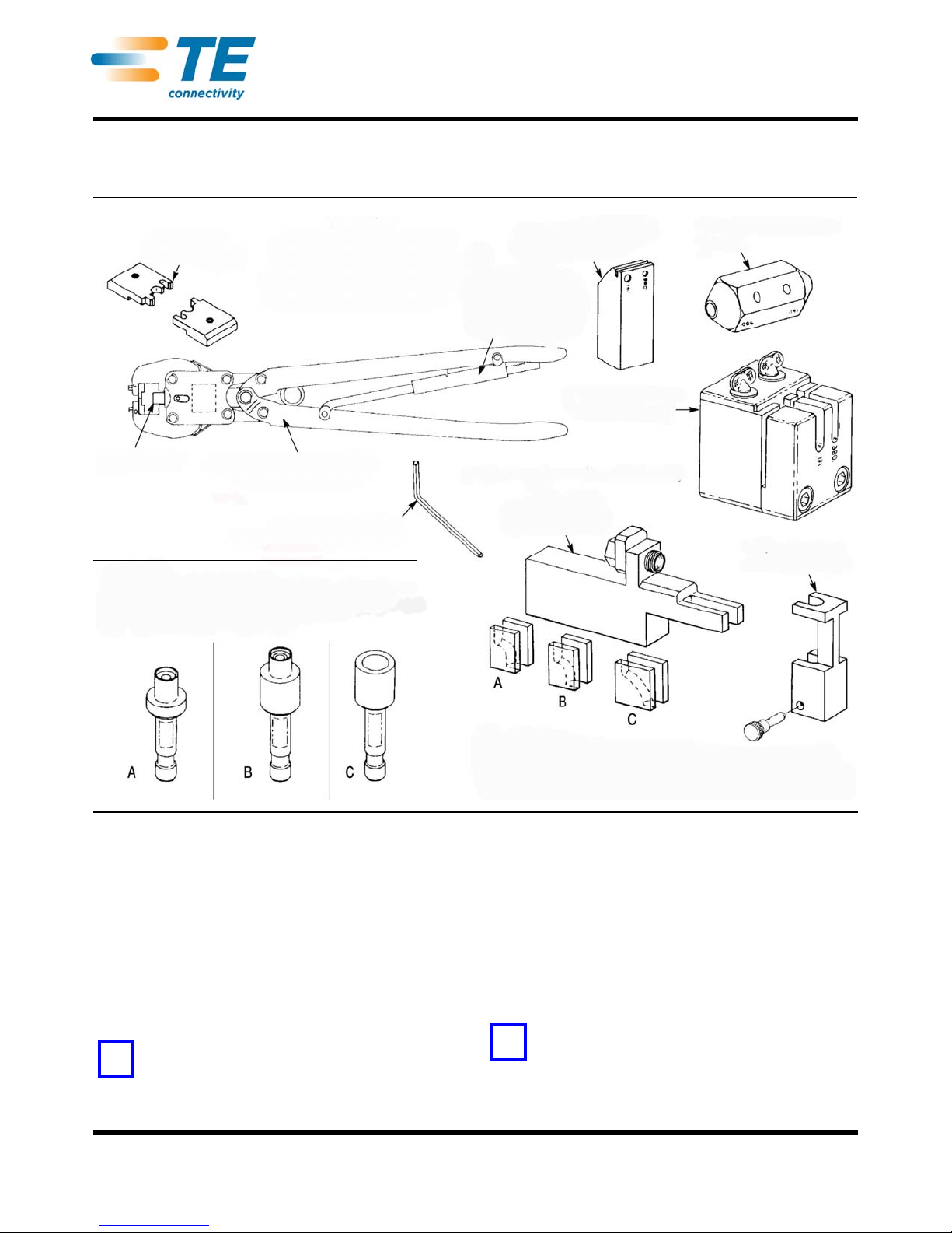
Die Set (Typ)
Locator (Typ)
Hand Crimping Tool
59980-1 (36-01)
Kit 59981-1
Kit contains all the parts listed;
part numbers in parenthesis are
per MIL22520. All components
listed can be ordered separately
for specific application needs.
CERTI-CRIMP*
Hand Crimping Tool
Ratchet Control
Hex Wrench (.094-in.) 21027-6
Cable Dressing Fixture
311396-1 (36-07)
Trimmer Tool 312317-1
(36-08)
Cable Cutoff Fixture
311395-1 (36-09)
Bend Tool Holder
311392-1 (36-10)
90 ° Bending Fixture Assembly (36-10)
Conforming Block
312067-1 (36-10)
Bend Segments:
A -- 311386-1 (36-11) for RG-402, 3.17mm [.125 in]. Radius
B -- 311386-2 (36-12) for RG-402, 6.35mm [.250 in.] Radius
C -- 311386-3‘(36-13) for RG-405, 3.17mm [.125 in.] Radius
Locators:
A -- 220221-2 (36-04) for Plugs with Center Contact
B -- 220220-2 (36-06) for Plugs without Center Contact
C -- 220222-2 (36-05) for Jacks
NOTE
i
NOTE
i
Hand Crimping Tool and Cable
Preparation Kit 59981-1
408-6788
23 AUG 13 Rev L
ORIGINAL INSTRUCTIONS
1. INTRODUCTION
Hand Crimping Tool and Cable Preparation Kit
59981-1 (shown in Figure 1) is used to prepare and
terminate RG-402 (3.581mm [.141 in.] outside
diameter) and RG-405 (2.184mm [.086 in.] outside
diameter) semi-rigid coaxial cable onto SMA Series,
N Series, and TNC Series connectors listed in
Figure 2. Read these instructions thoroughly before
using the kit.
NOTE
Dimensions in this instruction sheet are in millimeters
[with inches in brackets]. Figures and illustrations are for
reference only and are not drawn to scale.
Figure 1
Reasons for reissue of this instruction sheet are
provided in Section 11, REVISION SUMMARY.
2. DESCRIPTION
The kit contains a hand crimping tool (with a
CERTI-CRIMP hand crimping tool ratchet control), two
interchangeable die sets (one for RG-402 cable and
the other for RG-405 cable), and three locators for
specific connector terminations. See Figure 1.
NOTE
The tool ratchet ensures full crimping of the connector.
Once engaged, the ratchet will not release until the
handles have been FULLY closed. Do NOT adjust the
ratchet.
©2013 Tyco Electronics Corporation, a TE Connectivity Ltd. company
All Rights Reserved
*Trademark
TE Connectivity, TE connectivity (logo), and TE (logo) are trademarks. Other logos, product and/or company names may be trademarks of their respective owners.
TOOLING ASSISTANCE CENTER
PRODUCT INFORMATION
1-800-722-1111
1-800-522-6752
This controlled document is subject to change.
For latest revision and Regional Customer Service,
visit our website at www.te.com
1 of 12

408-6788
1
TE
Dies
2
Locator
CONNECTOR TYPE FOR
RG-402 CABLE
TE
PART NUMBERS
CATEGORY B CATEGORY F HAND TOOL 59980-1
Military
M39012/
TE
Military
M39012/
Plug with Center Contact --- 79B3104 227743-1 79-3308 228634-1 312253-1 220221-2
Plug with Center Contact and
Safety Wire Holes
Sealed Plug with Center
Contact
Sealed Plug with Center
Contact and Safety Wire Holes
228634-4 --- --- --- --- 312253-1 220221-2
221328-1 --- --- --- --- 312253-1 220221-2
221328-2 --- --- --- --- 312253-1 220221-2
Plug without Center Contact 228635-2 92B3103 227531-1 92-3301 228635-1 312253-1 220220-2
Sealed Plug with Center
Contact and Safety Wire Holes
221328-2 --- --- --- --- 312253-1 220221-2
Plug without Center Contact 228635-2 92B3103 227531-1 92-3301 228635-1 312253-1 220220-2
Plug without Center Contact
and with Safety Wire Holes
Sealed Plug without Center
Contact
228635-4 --- --- --- --- 312253-1 220220-2
221329-1 --- --- --- --- 312253-1 313585-1‡
2
Plug with Retractable Collar
Sealed Plug with Retractable
Collar
Sealed Plug with Retractable
Collar and Safety Wire Holes
227531
227531-6
--- --- --- --- 312962-1‡ 220220-2
221329-3 --- --- --- --- 312962-1‡ 313585-1‡
221329-4 --- --- --- --- 312962-1‡ 313585-1‡
Right-Angle Plug 228626-2 --- --- 80-3308 228626-1 312253-1 312173-1‡
Right-Angle Plug with Safety
Wire Holes
Sealed Right-Angle Plug with
Safety Wire Holes
228626-4 --- --- --- --- 312253-1 312173-1‡
222066-2 --- --- --- --- 312253-1 312173-1
Jack 228636-2 --- --- 81-3208 228636-1 312253-1 220222-2
4-Hole Panel Jack 228637-2 --- --- --- --- 312253-1 220222-2
Bulkhead Jack 228638-2 83B3004 227746-1 83-3208 228638-1 312253-1 220222-2
N Series Connectors:
Front-Mounted Jack
Rear-Mounted Jack
Plug
TNC Series Connectors:
Rear-Mounted Jack Plug
228448-1
228658-1
228440-1
228502-1
228179-2
--- --- --- --- 312253-1 220222-2
--- --- --- --- 312253-1 220222-2
Adapter Assemblies 228446-1† --- --- --- --- 312253-1 220222-2
1. Consult latest issue of MIL-C-39012 and QPL for current military dash numbers.
2. All items are included in Kit 59981-1, except those marked with ‡
† For both N Series and TNC Series
Rev L
Figure 2 (Cont’d)
2 of 12

408-6788
1
TE
Dies
2
Locator
CONNECTOR TYPE FOR
RG-405 CABLE
TE
PART NUMBERS
CATEGORY B CATEGORY F HAND TOOL 59980-1
Military
M39012/
TE
Military
M39012/
Plug with Center Contact --- 79B3103 227868-1 79-3307 228639-1 312253-2 220221-2
Plug with Center Contact and
Safety Wire Holes
Short Plug with Center Contact
Short Plug with Center Contact
and with Safety Wire Holes
228639-4 --- --- 79-3207 228639-3 312253-2 220221-2
221447-1
221447-2
221447-3
221447-4
--- --- --- --- 313113-1‡ 220221-3‡
--- --- --- --- 313113-1‡ 220221-3‡
Sealed Short Plug 221812-1 --- --- --- --- 313113-1‡ 220221-3‡
Sealed Short Plug with Safety
Wire Holes
Short Plug with Retractable
Collar
221812-2 --- --- --- --- 313113-1‡ 220221-3‡
221447-5 --- --- --- --- 313113-1‡ 220221-3‡
Right-Angle Plug 228583-2 --- --- 80-3307 228583-1 312253-2 312173-1‡
Right-Angle Plug with Safety
Wire Holes
228583-4 --- --- 80-3207 228583-3 312253-2 312173-1‡
2
Sealed Right-Angle Plug 222264-1 --- --- --- --- 312253-1 312173-1
Sealed Right-Angle Plug with
Safety Wire Holes
222264-2 --- --- --- --- 312253-1 312173-1
Jack 228640-2 --- --- 81-3207 228640-1 312253-2 220222-2
4-Hole Panel Jack --- 82B3003 227870-1 82-3207 228641-1 312253-2 220222-2
Bulkhead Jack
TNC Series Connector:
Rear-Mounted Jack
Adapter Assembly
(For TNC Series Only)
1. Consult latest issue of MIL-C-39012 and QPL for current military dash numbers.
2. All items are included in Kit 59981-1, except those marked with ‡
† For both N Series and TNC Series
227871-3
228642-2
83B3003 227871-1 83-3207 228642-1 312253-2 220222-2
228507-1 --- --- --- --- 312253-2 220222-2
228505-1† --- --- --- --- 312253-2 220222-2
Figure 2 (End)
Rev L
3 of 12

408-6788
NOTE
i
Cable Preparation-Strip Length and Pointing
Detail A
Recommended•
Detail B
Optional
90°
60-90°
Deburr Around Edge of
Center Conductor
Note: Not to Scale
Strip Length
•Required on cables
terminated to connectors
without center contacts
NOTE
i
NOTE
i
NOTE
i
Cable Cutoff Fixture
Cable Size
Designations
.086
.141
Clamp
Screws
Cable
Saw Blade
in Slot
NOTE: Enter preformed cable from this end of fixture if cut
end is desired up to 12.70 mm [.500 in.] of cable bend radius.
Minimum straight cable length of 12.70 mm [.50 in.] is
required for cable bend to clear tool head during crimping.
The kit also includes the following cable preparation
tools: cable dressing fixture, trimmer tool, cable cutoff
fixture, and 90° bending fixture assembly.
NOTE
Special die sets and special locators are NOT supplied
with Kit 59981-1. These items MUST be ordered
separately. They include: (1) RG-402 cable, Die Set
312962-1 for plugs with retractable collars, and Locator
313585-1 for sealed plugs without center contacts; and
(2) RG-405 cable, Die Set 313113-1, and Locator
220221-3 for short plugs, and Locator 312173-1 for
right-angle plugs.
3. CABLE, CONNECTOR, AND LOCATOR SELECTION
Select the correct combination of cable, connector,
hand tool locator, and die set from Figure 2.
4. CABLE PREPARATION
Semi-rigid cable must be properly prepared for
termination. Correct use of cable preparation tools
(cutoff fixture, dressing fixture, and trimming tool) will
give the strip length and recommende d po int ing as
shown in Figure 3, Detail A.
If TE Connectivity tools are not used for cable
preparation, strip the cable to the dimension shown,
and deburr (point) the center conductor as shown in
Figure 3, Detail B, then proceed directly to Section 5,
TOOL SETUP.
NOTE
All cable terminated with connectors without center
contacts must be pointed to ensure a sound connection.
3. Trim the cable dielectric to the strip length
dimension shown in Figure 3. Be careful to avoid
nicking the center conductor.
4. Brush the prepared cable end to remove any
metallic debris that might be present.
NOTE
The cable can also be prepared by using Semi-Rigid
Cable Stripping Machine 220211-2 with Stripping Kit
813599-[ ]. Refer to Customer Manual 409-2909 for
detailed operating procedures.
4.1. Cable Cutoff Fixture (Figure 4)
Clamp the cable to the fixture, with the cable in the
proper groove, and cut the cable end square ly with a
jeweler's saw with a 0.28 to 0.33 mm [.011 to .013 in.]
blade thickness.
NOTE
On preformed cables with 90° or 180° bends, a
minimum straight cable length of 12.70 mm [.500 in.] is
required to clear the tool head during crimping.
To prepare the cable:
1. Strip the outer cable jacket to the dimension
provided in Figure 3. Make sure that the cut is at a
90° angle to the cable length.
2. Point the center conductor.
Rev L
CABLE STRIP LENGTH DIMENSION
RG-402, RG-405 2.16 ±0.13 [.085 ±.005]
Figure 3
Figure 4
4.2. Cable Dressing Fixture and Trimmer Tool
1. Place the cable dressing fixture in a vise.
2. Insert the cable into the hole corresponding to the
cable size as shown in Figure 5, Detail A.
3. Using the jeweler's saw, carefu lly cu t thr ough th e
cable shield while rotating the cable, maintaining
pressure against the fixture.
4 of 12

408-6788
Slot for
Saw Blade
.086
.141
Cable
Using Cable Dressing Fixture
Vise
Detail A
Detail B
Insert Cable into Hole
and Saw Through
Jacket While Rotating
Cable
Rotate Cable Slowly
While Filing Across This
Surface to Form 45° Tip
on End of Conductor
!
After Slipping Trimmer Over
Cable, Rotate Trimmer (As
Shown) 2 or 3 Revolutions to
Smooth Copper Shield and
Dielectric
Holes
Cable Size
Designations
Cable
Using Trimmer Tool
NOTE
i
!
NOTE
i
2. Push lightly against the cable while slowly
rotating the trimmer tool clockwise several times.
3. Remove the trimmer tool and clean any chips
from the cable end.
4. Re-insert the cable into the cable dressing fixture
for pointing. Refer to Figure 5, Detail B. Keep
pressure against the fixture and rotate the cable
slowly while filing on the 45° surface with a small
pillar file or mill file. Continue filing until the
conductor offers no resistance to the file.
5. Remove the cable and brush off any chips.
NOTE
A final inspection must be performed to ensure that no
metal chips or burrs are present on the cable dielectric
surface or on the cable shield inner or outer surfaces.
5. TOOL SETUP (Figure 7)
Before prepared cable can be crimped to a connector,
the hand crimping tool must be set up with the
appropriate locator and die set. Proceed as follows:
1. Select the proper hand tool locator from Figure 2.
4. Remove the cable from the fixture. Using a razor
blade, carefully cut and remove the dielectric to
expose the center conductor.
CAUTION
DO NOT nick or score the center conductor.
T o smooth th e copper shield and dielectric, proceed as
follows:
1. Slip the correct end of the trimmer tool over the
exposed cable end. See Figure 6.
Figure 5
Figure 6
2. Loosen the locator locking screw, insert the
locator into the tool head cavity, making sure that
the locator is bottomed in the cavity, then re-tighten
the locking screw. Refer to Figure 7, Detail A.
3. Select the proper die set for either RG-402 or
RG-405 cable. Position each die on the respective
tool jaw and make sure that the chamfer is oriented
as shown in Figure 7, Detail A.
CAUTION
An unacceptable crimp will result if the die chamfers are
not positioned as shown.
4. Fasten the dies to the jaws with the screws, but
do not tighten the screws until the dies are aligned.
5. To align the dies, place the cable inside the
locator and squeeze the tool handles to close the
tool. Check for even alignment of the dies, as
shown in Figure 7, Detail B, then tighten the screws
to secure the dies.
6. CRIMPING PROCEDURE
NOTE
Before crimping, insert the prepared cable into the
BACK of the connector assembly until the cable bottoms
on the shoulder of the connector assembly.
6.1. For Connectors with Fixed Collars
(Except Right Angle Connectors)
Figures 8 and 9 show typical plug and panel jack
connectors with fixed collars.
Proceed as follows:
1. Carefully insert the cable into the connector until
the cable bottoms on the shoulder of the connector.
Rev L
5 of 12

Figure 7
Tool Setup
Die-Holding Hex Head
Screws (Captive)
Detail A
Detail B
Locator Locking
Screw (Ref)
Chamfer
Chamfer
Locator
(Typ)
Slip Cable in Locator
Between Dies. Tighten
Screws While Cable Holds
Dies in Proper Alignment
Center Conductor
of Connector Must
Enter Hole in
Locator
Crimping Connectors with Fixed Collars
(Except Right-Angle Connectors)
Connector with
Fixed Collar
Dies will Close Against
Cable and Connector to
Complete Termination
408-6788
2. Place the connector and cable inside the tool
locator, making sure that:
— the center conductor of center contact enters the
locator hole
— the connector is seated squarely on the locator
— if crimping a panel jack to the cable, the sides of
the panel jack should align with the tool jaws as
shown in Figure 9
3. Support the cable-and-connector assembly, and
squeeze the tool handles to complete the crimp as
shown in Figure 9.
6.2. For Connectors with Retractable Collars
Connectors with sliding coupling nuts (shown in Figure
10) require Special Die Set 312962-1 which is not
included in the kit and MUST be ordered separately.
Proceed as follows:
1. Slide the nut then the connector body, flange end
first, onto the cable.
2. Place the connector body and cable inside the
tool locator, making sure that the center conductor
enters the locator hole, and that the coupling nut is
positioned above the tool head.
Rev L
Figure 8
6 of 12

408-6788
Sides of Panel Jack
Align with Dies as
Tool Jaws Close
Panel Jack
Crimping Connectors with Fixed Collars
Crimping Connectors with
Retractable Collars
Coupling Nut
(Retractable)
Connector
Body
Coupling Nut Positioned
Above Tool Head During
Crimping
Special Die
Set 312962-1
Chamfer
Cable
Crimping Right-Angle Connectors
Right-Angle
Connector
Connector Collar
Facing Forward
Locator
Knob
Collar
Crimped
Connector
3. Squeeze the tool handles to crimp the connector
body to the cable.
Figure 9
— the connector collar faces forward, as shown in
Figure 11
3. Support the cable and connector assembly, and
squeeze the tool handles together to complete the
crimp.
6.3. For Right-Angle Connectors
Right-angle connectors require Locator 312173-1
which is not included in the kit and MUST be ordered
separately. Proceed as follows:
1. Slide the connector, flange end first, over the
cable end as shown in Figure 11.
2. Place the connector and cable inside of the tool
locator, making sure that:
— the recessed area of the connector body sits
squarely on the locator knob
Rev L
Figure 10
Figure 11
7. INTERNAL REFERENCE PLANES FOR CABLE
The dimensions shown in Figure 12 are from the
cable-bottoming surface or plane in the connector to
the mating reference plane.
8. CABLE BENDING
The 90° bending fixture assembly is used to make
precise right-angle bends on the cable near SMA
plugs as shown in Figure 13. Bends can have a radius
of 3.18mm [.125 in.] (on RG-402 or RG-405 cable),
6.35mm [.250 in.] (on RG-402 cable only), or 1.57mm
[.062 in.] (on RG-405 cable only).
The spacer shown in Figure 14 must be positioned
behind the dummy jack when bending:
— RG-402 cable to either 3.18mm [.125 in.] or
6.35mm [.250 in.] radii terminated onto plugs
with center contacts
— RG-405 cable to 1.57mm [.062 in.] or 3.18mm
[.125 in.] radii when terminated onto plugs with
center contacts except Short Plugs 221447-[ ].
For short plugs, a special spacer is required and
MUST be ordered separately from Special Kit
220224-2
Loosen the dummy jack to insert the spacer, and retighten the jack before proceeding.
7 of 12

408-6788
Plugs with Center Contacts (All Sizes)
Reference
Plane
Cable-Bottoming Plane
4.50 ±0.25 [.177 ±.010]
Right-Angle Plugs
Mating Interface Centerline
Cable-Bottoming Plane
3.76 ±0.25 [.148 ±.010]
Panel Jacks (All Sizes)
Reference
Plane
Cable-Bottoming Plane
6.48 ±0.25 [.259 ±.010]
90° Bend Plug Assemblies
(Plug Applied Before Bending Cable)
Interface
6.35 [.250]
Radius
6.35 [.250]
Radius
Interface
1.57 [.062]
Radius
8.1. To Make 6.35 mm [.250 in.] Bends on RG-402 Cable
or 3.18 mm [.125 in.] Bends on RG-405 Cable
1. Screw the terminated plug onto the dummy jack
of the tool holder. See Figure 15.
2. Slip the appropriate bend segment under the
cable as shown in Figure 15.
3. Using finger pressure, bend the cable around the
segment to the desired angle, to a 90° maximum.
4. Unscrew the plug from the tool holder.
8.2. To Make 3.18mm [.125 in.] Bends on RG-402 Cable
(Figure 16)
1. Make the 6.35mm [.250 in.] radial bend as
described in Paragraph 8.1, and remove the plug
from the tool holder.
2. Replace the 6.35mm [.250 in.] bend segment with
the 3.18 mm [.125 in.] segment for RG-402 cable.
3. Re-attach the plug to the dummy jack of the tool
holder.
4. Place the conforming block over the cable with
the tongue of the block in the slot of the tool holder,
as shown in Figure 16.
5. Insert the limiting pin and slide the block against
the opening.
Figure 12
SMA PLUG TYPE
CABLE
SIZE
6.35 [.250] RADIUS 3.18 [.125] RADIUS 1.57 [.062] RADIUS
ABABAB
DIMENSION
Plugs without Center Contact
Plugs without Center Contact 19.18 [.755] 22.61 [.890] 16.00 [.632] 19.43 [.765] --- --Plugs with Center Contact
Short Plugs --- --- 12.70 [.500] 15.88 [.625] 11.10 [.437] 14.27 [.562]
RG-402
RG-405
14.68 [.578] 18.11 [.713] 11.51 [.453] 14.94 [.588] --- ---
--- --- 15.34 [.604] 18.75 [.738] 13.72 [.540] 17.14 [.675]
Rev L
Figure 13
8 of 12
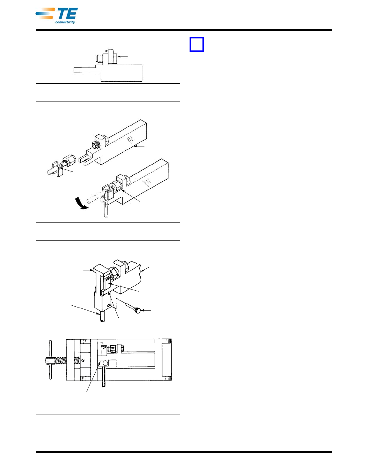
Figure 14
Spacer Used
with SMA Plugs
Dummy Jack
Cable Bending
Bending RG-402 Cable to 6.35mm [.250 in.] Radius or
RG-405 Cable to 3.18mm [.125 in.] Radius
Bend Segment
Oriented Properly
Plugs Screwed
onto Tool Holder
Tool Holder
Apply Finger Pressure
Bending RG-402 Cable to 3.18 mm [.125 in.] Radius
Tool Holder
Tongue
Cable Previously
Formed to 6.35
[.250] Radius
Bend
3.18 [.125]
Radius Bend
Segment
Limiting Pin
Conforming
Block Shoulder
Legs of Tool Holder Prevent Further
Movement of Vise Against Conforming Block
NOTE
i
408-6788
NOTE
Make sure that the shoulders of the conforming block
bear on the bottom surface of the tool holder BEFORE
applying pressure in the vise.
7. Tighten the vise to force the conforming block into
the slot. Continue to tighten until the legs of the tool
holder prevent further movement of the vise jaws.
8. Remove the assembly from the vise, and
unscrew the plug from the fixture.
9. Remove the conforming block and bend
segment.
8.3. To Make 1.57 mm [.062 in.] Bends on RG-405 Cable
It is recommended that a special kit be used to make
1.57 mm [.062 in.] bends on RG-405 cable. Kit
220224-2 includes a limiting pin, a 90° bend tool body
assembly, a 90° bend segment, and a conforming
block. The figures referenced for the 6.35 mm
[.250 in.] and 3.18 mm [.125 in.] bends will assist in
making the 1.57 mm [.062 in.] bends. These steps are
recommended:
Figure 15
1. Make the 3.18 mm [.125 in.] radial bend as
described in Paragraph 8.1, and remove the plug
from the tool holder.
2. Replace the 3.18 mm [.125 in.] bend segment
with the special 1.57 mm [.062 in.] bend segment,
which is a part of Kit 220224-2.
3. Re-attach the plug to the dummy jack of the tool
holder.
4. Place the special 1.57 mm [.062 in.] conforming
block over the cable with the tongue of the block in
the tool holder slot. The conforming block is part of
Kit 220224-2.
5. Insert the limiting pin and slide the block against
the tool holder.
6. Place the assembly in a vise with a 69.85 mm
[2.75 in.] opening.
7. Remove the assembly from the vise, and
unscrew the plug from the fixture.
8. Remove the assembly from the vise, and
unscrew the plug from the fixture.
9. Remove the special conforming block and special
bend segment.
6. Place the assembly in a vise with a 69.85 mm
[2.75 in.] opening.
Rev L
Figure 16
9. MAINTENANCE AND INSPECTION
Hand Crimping Tool and Cable Preparation Kit
59981-1 is inspected before shipment. The tool and kit
should be inspected immediately upon arrival to
ensure that they have not been damaged during
shipment, and that they perform according to the
criteria described in this sheet. If the tool and kit are
damaged upon arrival, retain the shipping container,
file a claim with the carrier, and notify TE immediately.
9 of 12

9.1. Daily Maintenance
Suggested Plug Gage Design
63.5 [2.5] (Typ)
6.35 ±0.25 [.25 ±.01]
12.7 [.50]
12.7 [.50]
NO-GO
GO
Inspection of Crimping Chamber
Top of Ram
Crimping Chamber
16.0 ±0.08
[.630 ±.003]
Stop
Surface
GO Element
NO-GO Element
Crimping
Chamber
Crimping
Chamber
12.2 ±0.25
[.48 ±.010]
GO element must
pass completely
through the
crimping chamber.
NO-GO element may
enter partially, but must
not pass completely
through the crimping
chamber.
Die Inserts
312253-1
(Required)
GO/NO-GO
Gage
1. Remove dust, moisture, and other contaminants
from the tool with a clean brush or a soft, lint-free
cloth. Do NOT use objects that could damage the
tool.
2. Make sure that the proper retaining pins are in
place and are secured with the proper retaining
rings.
3. Make certain that all pins, pivot points, and
bearing surfaces are protected with a THIN coat of
any good SAE 20 motor oil. Do NOT oil excessively.
4. When the tool is not in use, keep the handles
closed to prevent objects from becoming lodged in
the crimping chambers and store the tool in a clean,
dry area.
9.2. Periodic Inspection
Regular inspections should be performed by quality
control personnel. A record of scheduled inspections
should remain with the tool and/or be supplied to
supervisory personnel responsible for the tool. Though
recommendations call for at least one inspection per
month, the inspection frequency should be based on
the amount of use, working conditions, operator
training and skill, and established company standards.
These inspections should be performed in the
following sequence:
408-6788
GAGE ELEMENT DIAMETERS
GO NO-GO
15.915-15.920 [.6266-.6268] 16.078-16.083 [.6330-.6332]
A. Visual Inspection
1. Remove all lubrication and accumulated film by
immersing the tool (handles partially closed) in a
suitable commercial degreaser that will not affect
paint or plastic material.
2. Make certain that all retaining pins are in place
and are secured with retaining rings. If
replacements are necessary, refer to Section 10,
REPLACEMENT AND REPAIR.
3. Inspect crimping chambers for pitted or chipped
surfaces.
4. Close the tool handles until the ratchet releases,
then allow handles to open freely. If they do not
open quickly and fully, the spring is defective and
must be replaced. Refer to Section 10,
REPLACEMENT AND REPAIR.
B. Gaging the Crimping Chambers
This inspection requires the use of a plug gage
conforming to the dimensions listed in Figure 17. TE
does not manufacture or market these gages. To gage
the crimping chambers, proceed as follows:
1. Insert Die Set 312253-1 as described in
Section 5, TOOL SETUP. Do NOT insert the locator.
2. Close the tool handles until the ram touches the
stop surfaces. Refer to Figure 17.
Rev L
Figure 17
3. Align the GO element of the gage with the
crimping chamber so that the top and bottom of the
gage align with the surfaces of the die inserts and
ram.
4. Push the element straight into the crimping
chamber without using force. The GO element must
pass completely through the crimping chamber as
shown in Figure 17.
10 of 12

5. Align the NO-GO element and try to insert it
CUSTOMER SERVICE (038-035)
TYCO ELECTRONICS CORPORATION
PO BOX 3608
HARRISBURG PA 17105-3608
straight into the crimping chamber. The NO-GO
element may start entry, but must not pass
completely through the crimping chamber , as shown
in Figure 17.
408-6788
If the crimping chamber conforms to the gage
inspection, the tool is considered dimensionally
correct. If the crimping chamber does not conform to
the inspection, the tool must be repaired before
returning it to service. Refer to Section 10,
REPLACEMENT AND REPAIR.
For additional information concerning the use of the
plug gage, refer to Instruction Sheet 408-7424.
C. CERTI-CRIMP Hand Crimping Tool Ratchet Control
Inspection
Obtain a .0254 mm [.001 in.] shim that is suitable for
checking the clearance between th e ra m an d stop
surfaces. To inspect the ratchet:
1. Squeeze the tool handles together until the
ratchet releases. Allow the handles to open FULLY.
2. Place the shim between the top of the ram and
the stop surfaces.
3. Support the shim and squeeze the tool hand les
together until the ratchet releases, then HOLD the
tool handles in this position.
4. Check the clearance between the ra m an d the
stop by trying to remove the shim. If shim cannot be
removed, lubricate it with a THIN coat of any good
SAE 20 motor oil and return it to service. If the shim
can be removed, the ratchet is out of adjustment
and must be repaired. Refer to Section 10,
REPLACEMENT AND REPAIR.
10. REPLACEMENT AND REPAIR
Customer-replaceable parts for the cable preparation
kit are listed in Figure 18, and customer-replaceable
parts for the hand crimping tool ar e listed in Figure 19.
A complete inventory should be stocked and
controlled to prevent lost time when replacement of
parts is necessary. Replacement parts can be ordered
from:
Parts other than those specified in Figures 18 and 19
must be replaced to ensure correct operation of the
tool. For customer repair service, please contact an
TE Representative at 1-800-526-5136.
CABLE PREPARATION KIT REPLACEMENT PARTS
TE
PART
NUMBER
59980-1 36-01
220220-2 36-06 Plug Locator without Center Contact
220221-2 36-04 Plug Locator with Center Contact
220222-2 36-05 Jack Locator
312253-1 36-03 Dies (2 for RG-402 Cable)
312253-2 36-02 Dies (2 for RG-405 Cable)
21027-6 --- Hex Wrench, .0938-in.
311395-1 36-09 Cutoff Fixture
311396-1 36-07 Cable Dressing Fixture
312317-1 36-08 Trimmer Tool
220224-1 36-10 90_ Bending Fixture Assembly
311386-3 36-13
311386-2 36-12
311386-1 36-11
311392-1 36-10 Bend Tool Holder
312067-1 36-10 Conforming Block
307581-1 36-10 Limiting Pin
13126-1 --- Carrying Case
13127-1 --- Case Insert
MILITARY
PART
NUMBER
22520/
DESCRIPTION
Hand TooL (Locator and Dies Not
Included with Tool)
Bend Segment, RG-405,
3.18 mm [.125 in.] Radius
Bend Segment, RG-402,
6.35 mm [.250 in.] Radius
Bend Segment, RG-402,
3.18 mm [.125 in.] Radius
Figure 18
Rev L
11. REVISION SUMMARY
•Updated document to corporate requirements
•Changed artwork in Figures 7, 8, 9, 10, 11, and 17
11 of 12

408-6788
305 [12]
24 [.94]
69.8 [2.75]
(Closed)
Weight: 0.9 kg [2 lb]
HAND CRIMPING TOOL REPLACEMENT PARTS
ITEM PART NUMBER DESCRIPTION QTY PER TOOL
1 300388 PIN. Retaining 2
2 21045-3 RING, Retaining 8
3 300389 PIN. Retaining 1
4 21045-6 RING, Retaining 6
5 305340 PIN. Retaining 2
6 305340 PIN. Retaining 2
7 2-304668-9 SPRING 1
8 21028-5 PIN, Slotted Spring 2
9 312065-1 SCREW, Special 2
Figure 19
Rev L
12 of 12

Mouser Electronics
Authorized Distributor
Click to View Pricing, Inventory, Delivery & Lifecycle Information:
TE Connectivity:
59981-1
 Loading...