

Page 1
EN
Instruction Manual
TechniSat
TechniNet
Base Unit &
IP IRD-Cards
DVB-S2
DVB-C
DVB-T
www.technisat.de
www.technisat.com
1
Page 2

EN
Content
1 Safety advice.................................................................................................................................. 4
2 General ............................................................................................................................................ 6
2.1 Description ......................................................................................................................................................... 6
2.2 Description of the operating elements ................................................................................................. 7
3 Bringing into service .................................................................................................................. 8
3.1 Assembling ......................................................................................................................................................... 8
3.2 Connection to the network ......................................................................................................................... 8
3.2.1 LAN ......................................................................................................................................................................... 8
3.2.2 TS/IP ..................................................................................................................................................................... 8
3.2.3 Handset ................................................................................................................................................................ 9
3.2.4 TUNER IN ............................................................................................................................................................ 9
3.2.5 LOOP THRU ........................................................................................................................................................ 9
3.2.6 ASI OUT ................................................................................................................................................................ 9
3.2.7 ASI2/SDI OUT1 ................................................................................................................................................. 9
3.2.8 ASI IN .................................................................................................................................................................... 9
3.2.9 CVBS ...................................................................................................................................................................... 9
3.2.10 AV OUT ................................................................................................................................................................. 9
4 Programming .............................................................................................................................. 10
4.1 Programmer ................................................................................................................................................... 11
4.1.1 Menu structure .............................................................................................................................................. 11
4.2 Connection of the programmer Remote Control .......................................................................... 17
4.3 Main Menu, System ..................................................................................................................................... 18
4.3.1 LAN Interface .................................................................................................................................................
4.3.2 Trap-IP .............................................................................................................................................................. 19
4.3.3 Module name .................................................................................................................................................. 19
4.3.4 Firmware version ......................................................................................................................................... 20
4.3.5 Factory settings ............................................................................................................................................. 21
4.3.6 TS/IP Interface .............................................................................................................................................. 21
4.3.7 HTTP Login...................................................................................................................................................... 22
4.4 Main Menu, Inputs ....................................................................................................................................... 23
4.4.1 DVB-S2 reception ......................................................................................................................................... 23
4.4.2 DVB-C reception ........................................................................................................................................... 25
4.4.3 DVB-T reception ........................................................................................................................................... 26
4.4.4 Multicast-reception ..................................................................................................................................... 27
4.4.5 Monitoring of the RSSI Data .................................................................................................................... 29
4.4.6 Request input status .................................................................................................................................. 29
4.5 Main Menu, Outputs .................................................................................................................................... 30
4.5.1 TS/IP Interface configured ...................................................................................................................... 30
4.5.1.1 Uni-/Multicast play out ............................................................................................................................. 33
4.6 Web-Interface ................................................................................................................................................ 37
4.6.1 Status .................................................................................................................................................................. 37
4.6.2 Input ................................................................................................................................................................... 39
4.6.2.1 DVB-S2............................................................................................................................................................... 39
4.6.2.2 DVB-C ................................................................................................................................................................. 40
4.6.2.3 DVB-T ................................................................................................................................................................. 41
4.6.3 Output ................................................................................................................................................................ 41
4.6.3.1 ASI Output........................................................................................................................................................ 41
18
2
Page 3
EN
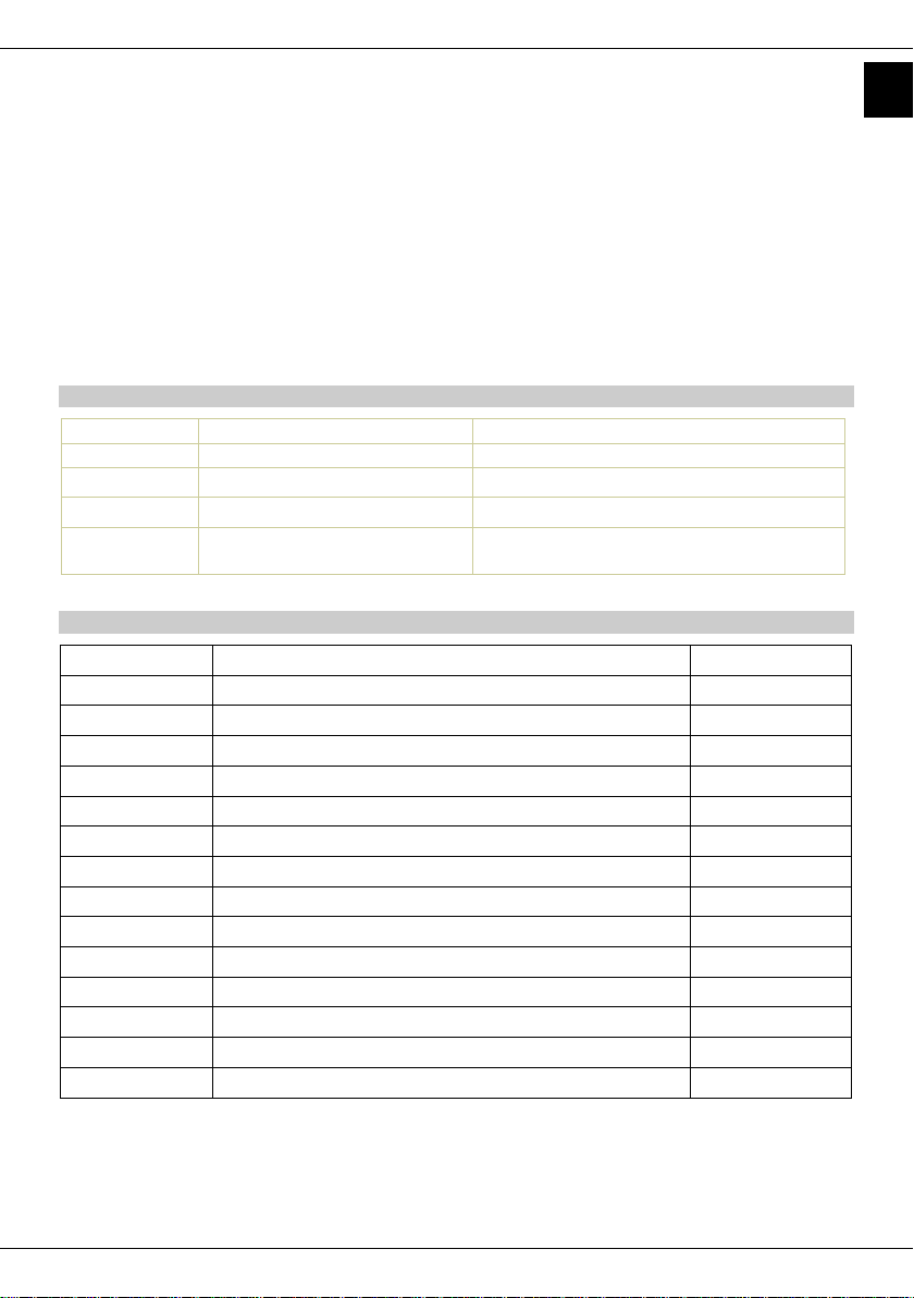
Artikel No.
Description
0000/5972
TechniNet IP DVB-S2/IP
DVB-S2 IRD-Card (x6 Multicast Channels)
0000/5975
TechniNet IP DVB-C/IP
DVB-C IRD-Card (x6 Multicast Channels)
0000/5976
TechniNet IP DVB-T/IP
DVB-T IRD-Card (x6 Multicast Channels)
0000/5977
TechniNet IP DVB-S2/IP 32M
DVB-S2 IRD-Card (x32 Multicast
Channels)
RSSI
Received Signal Strength Indication
ASI
Asynchronous Serial Interface
DiSEqC
Digital Satellite Equipment Control
FBAS
Farb-Bild-Austast-Synchron-Signal
IRD
Integrated Receiver Decoder
MTPS
Multiple Program Transport Stream
PES
Packetized Elementary Stream
PSI
Program Specific Information
RTP
Real-Time Transport Protocol
SDI
Serial Digital Interface
SI
Service Information
SNMP
Simple Network Management Protocol
SPTS
Single Program Transport Stream
TSoIP
Transport Stream over Internet Protocol
UDP
User Datagram Protocol
4.6.3.2 ASI2/SDI Output ........................................................................................................................................... 42
4.6.3.3 Decoder Play ................................................................................................................................................... 43
4.6.3.4 Decoder Config .............................................................................................................................................. 44
4.6.4 CI .......................................................................................................................................................................... 46
4.6.5 IP In/Out ........................................................................................................................................................... 47
4.6.5.1 Uni-/Multicast play out ............................................................................................................................. 48
4.6.6 System ............................................................................................................................................................... 51
5 Technical Data ............................................................................................................................ 54
5.1 Input ................................................................................................................................................................... 54
5.2 Output ................................................................................................................................................................ 55
5.3 Configuration, Monitoring ....................................................................................................................... 55
5.4 General .............................................................................................................................................................. 56
This manual is describing the following pages:
List of used abbreviations
3
Page 4

EN
1 Safety advice
For your own safety you should read this first and carefully – please pay attention to the
given advice before you start operating the device.
All assembling and installations have to be carried out by professional staff. Professionals are
persons who have an extended knowledge in the area of Sat Equipment installations and are
also familiar with the safety and emergency standards. In addition they should be familiar
with governmental rules and standards (e.g. DIN) that are applicable for the assembling of
such a device.
For your own protection you are advised to read the safety precautions carefully before
using the set.
The manufacturer will not assume liability for any damages caused by improper handling or
by not following the safety precautions properly.
In the following situations you should unplug the set from the mains power and seek
professional help:
> If the power cable or plug is damaged
> If the set has been subjected to dampness or liquid has entered.
> If there is a serious malfunction
> If it has suffered serious external damage
Special Risk- and Positioning Advice:
Notes on dangers and setting up which need your particular attention:
Mains connection:
> It is only permitted to use an adequate mains socket 0f 230 V as voltage source.
> Position the mains cable so that nobody will trip over it.
Location:
> The ambient temperature must be between 0 and 40 °C.
4
Page 5

EN
> The device may only be kept in rooms (away from radiated heat or heat sources), where,
even if the climatic conditions change, the permissible surrounding temperatures can be
assured.
> Do not subject the set to any spray or dripping water..
> Liquid-filled objects are not allowed to be placed on the set.
> Only mount it to vertical surfaces.
> Keep the ventilation slots clear (30 cm each from the top and bottom).
> Ensure good ventilation (do not fit in cupboards or niches).
> In the event of water condensation, wait until the set has dried out completely.
> If the sets are used in conjunction with BS 3 fans to maintain the permissible surrounding
temperature, it is essential that additional suitable measures are taken to ensure that in the
event the fan stops, the set is switched off (disconnection from the mains).
Please note:
> DIN VDE regulations 0701, Parts 1 and 200.
> EN 50 083 - Part 1, safety requirements.
> The set may only be opened by qualified professionals (dealership).
> Repairs may only be carried out by qualified professionals (dealership), or the faulty set may
be returned to TechniSat with a precise description of the fault(s).
For your safety:
> Observe the above rules and notes.
> Set up the SAT set in accordance with the safety requirements
> Observe the rules on grounding and potential equalisation
> Only replace the mains lead with an original mains lead
> Only replace fuses with fuses of the same type, value and the same melting characteristics.
> The mains fuse is in the fuse holder between the mains socket and the mains switch and is
accessible after removal of the mains lead.
It is essential that all safety notes are observed!
EMV security
The device has to be used with TechniNet IP base unit 0000/5970 only. The interfaces have to
be connected with appropriate shield cables only. The unused slots in the base unit have to be
covered with suitable front plate fittings.
5
Page 6

EN
2 General
2.1 Description
The TechniNet IP IRD cards receive a large number of channels of the DVB-S/S2, DVB-C or
DVB-T signal and transmit those as IPTV or TSoIP via Ethernet 100BaseT interfaces in your IP
based network. As network protocol UDP or RTP are used.
The equipment is fitted with a TWIN-CI interface which can, with the aid of up to two CAMs,
encrypt the channels directly through the card.
The integrated ASI-Input and ASI-output enables various applications for further transmission
of the signal. Alternatively a SDI-out is offered.
It is further possible to convert one of the existing services with the integrated MPEG-2 SD Decoder in a FBAS –AV signal. In addition the card has also the possibility to receive IPTV data
streams and process them accordingly.
Due to an integrated switch matrix various ways of operations are offered:
Picture: 3-1 block diagram
The TechniNet IP IRD cards are intended for use in the TEchniNet IP base unit. In this, 8
modules can be operated next to the redundant power supply.
The control of the device is either possible via a local cable connected programmer remote
control, via web interface or preferably with the TechniNet Management Software by Ethernet
via PC.
6
Page 7

EN
Element
Description
LAN
RJ-45 socket, network connection, full-duplex
TS/IP
RJ-45 socket, TSoIP-connection, half - duplex,
Input or output
POWER
LED, operational voltage display
LOCK
LED, Tuner lock display
IP RST
Button, IP Reset
RESET
Button, Card Reset
Remote Control
15pol. D-Sub socket,
for the connection of programmer unit
0000/5971
Common Interface
2x PCMCIA
Element
Description
TUNER IN
F-Socket, SAT-ZF In
LOOP THRU
F-Socket, SAT-ZF loop through
ASI OUT
BNC-Socket, ASI-out
ASI2/SDI OUT
BNC-Socket, ASI- or SDI-out
ASI IN
BNC-Socket, ASI-in
CVBS
BNC-Socket, FBAS-out
AV OUT
2,5mm jack plug
FBAS-out, Audio-out left/right
2.2 Description of the operating elements
Front view
Rear view
7
Page 8

EN
3 Bringing into service
ESD-safety
During operation of the device the ESD-safeguards in accordance with DIN EN 100
015-1 have to be observed. (Induced by a potential equalization between chassis
and equipment material as well as housing materials through high resistance
(approx. 1 MOhm), for example with a standard ESD-wristband).
3.1 Assembling
The operation of the module is solely carried out in one of the various slots of the TechniNet IP
base unit. Before bringing into service it should be noted that the device is within the range of
nominal temperature. After assembling the device is operable immediately.
The module is hot-plus capable. The integration and removal is thus possible during the
operation of the system.
The printed circuit has to be moved from the front of the device in between the appropriate
conductor till the terminal tag is connected with the printed circuit on the back. Afterwards
the front –and back plate have to be screwed to the chassis.
All possible and needed settings for the device can now be carried out with the TechniNet IP
Programmer (0000/5971) or the TechniNet Management Software.
3.2 Connection to the network
3.2.1 LAN
The module will be connected with the LAN RJ-45 socket via the Ethernet network. Through
this the control of the modules via the web-interface or via the TMS – TechniNet Management
Software (TMS) will be carried out. The factory site IP address is 10.10.70.48.
3.2.2 TS/IP
The TS/IP interface can be configured as in- or output (half-duplex) and enables the
transmission or reception of an IPTV-or TSoIP data stream.
Using for IPTV applications, the MPEG
transport stream received by the IRD-card
will play out into the network as so called
SPTS (Single program Transport Stream)
via a multicast-address into the network.
The needed information to recover
encoded TV programs is already integrated
into the SPTS. It only contains the video
and audio Information (PES).
In case of TSoIP application, the received
DVB-transport stream will be implemented
via Ethernet. The implemented transport
stream will be transmitted through a
Multicast Address.
8
 Loading...