

Page 1
Field strength
DigiMeter M3
Meter
Professional field strength Meter with
four digital Modulations
DVB-S, DVB-S2, DVB-C, DVB-T
Page 2

DIGIMETER M3
USER MANUAL
Thank you, that you have choosen our DigiMeter M3.
We hope you are satisfied with your decision, but if you do have any problem or Suggestions which
could lead to an improvement of our field strenght meters please write to
TechniSat Digital GmbH
Kunden- und Logistikzentrum
St. Laurentiusstraße 45
D-54550 Daun
www.technisat.com
Attention before you start the first time, do not forget to charge the
Battery !!!!!!
Charging time apr. 6 .. 8 hours.
UG-DIGIMETER-M3-1.06-BS1.1-EN-1.00
2
Page 3

DIGIMETER M3
USER MANUAL
INDEX
OVERVIEW .......................................................................................................8
1___ FRONT PANEL & KEYBOARD DESCRIPTION................................................................................ 8
2___ SIDE BODYPANELS....................................................................................................................... 9
2.1 RIGHTSIDE BODYPANEL..................................................................................................... 9
2.2 LEFTSIDE BODYPANEL....................................................................................................... 9
SPEEDY MEASUREMENTS ?.......................................................................10
3___ ONE TOUCH AND GO ...................................................................................................................10
3.1 ANALOGUE TV, DIGITAL (COFDM) TV AND QAM (CATV) SIGNALS..................................10
3.2 ANALOGUE SATELLITE SIGNALS, DIGITAL QPSK & 8PSK SATELLITE SIGNALS............10
3.3 FM / FM RADIO SIGNALS [87,5 – 108 MHz].........................................................................11
3.4 SPECTRUM ANALYZER FEATURE (ANY FREQUENCY)....................................................11
USER MANUAL..............................................................................................12
4___ TURN THE METER ON..................................................................................................................12
5___ TURN THE METER OFF ................................................................................................................12
6___ CHECK THE BATTERY CHARGE STATUS....................................................................................12
7___ THE ENCODER – STANDARD NAVIGATION MODE .....................................................................13
8___ METER CONFIGURATION............................................................................................................14
8.1 METER LOUDSPEAKER VOLUME SETUP..........................................................................14
8.2 METER SETUP....................................................................................................................14
____ BATTERY SAVING – SELF POWER OFF (TIMER OFF)..................................................14
____ FIELD AND CHANNEL POWER MEASUREMENT UNIT...................................................15
____ LANGUAGE.......................................................................................................................15
____ KEYS BEEP ......................................................................................................................15
____ DISPLAY BACKLIGHT.......................................................................................................15
8.3 MAIN RECEPTION PARAMETER SETUP............................................................................15
____ COUNTRY CHANNEL PLAN.............................................................................................15
____ LOCAL OSCILLATOR (FREQUENCY) .............................................................................15
____ RF INPUT SIGNAL TYPE (CABLE OR OFF AIR)...............................................................16
8.4 SATELLITE RECEPTION SETUP.........................................................................................16
____ LOCAL OSCILLATOR SETUP...........................................................................................16
____ LNB 1 ALLOWED POLARIZATION SETUP......................................................................16
____ LNB 2 ALLOWED POLARIZATIONS SETUP.....................................................................16
____ SINGLE-CABLE SCR COMPLIANT LNB OR MULTISWITCH SETUP : SAT SCR MENU...16
SatSCR USER:...............................................................................................................................17
SatSCR FREQ:...............................................................................................................................17
SatSCR CABLE..............................................................................................................................17
8.5 ADVANCED SETTINGS .......................................................................................................17
____ MANUAL SIGNAL STANDARD SELECTION.....................................................................18
9___ DC AT RF IN...................................................................................................................................19
TV SIGNALS – AUDIO FM – FM RADIO SIGNALS ANALYZER.................20
10__ SIGNAL TUNING: PLAN.................................................................................................................20
10.1 NAVIGATE INTO THE SELECTED COUNTRY CHANNEL PLAN.........................................20
10.2 NAVIGATE INTO THE CHANNEL PLAN (USER DEFINED CHANNEL PLAN)......................20
FINE-TUNING THE FREQUENCY VALUE.......................................................................................21
3
Page 4

DIGIMETER M3
USER MANUAL
DIRECT FREQUENCY INPUT.........................................................................................................21
WHO IS THERE?AUTODISCOVERY ®...........................................................................................22
____ FM /FM RADIO SIGNALS TUNING [87,5 – 108 MHz]........................................................23
10.3 EXPLORE USER DEFINED CHANNEL................................................................................24
11__ PERFORMING MEASURES: MEAS...............................................................................................25
11.1 THE SELECTED CHANNEL CARRIERS ON AN ANALOGUE TV SIGNAL...........................25
____ VIDEO SIGNAL PEAK LEVEL MEASUREMENT...............................................................25
____ VIDEO Vs. AUDIO PEAK LEVEL RATIO AND SIGNAL TO NOISE RATIO........................25
____ SPECTRUM ANALYSIS OF THE TUNED CHANNEL........................................................26
11.2 THE SELECTED CHANNEL CARRIERS ON A DTT (COFDM) SIGNAL...............................27
____ THE CHANNEL IS SUCCESSFULLY LOCKED (THE LOCK ON THE LCD BOTTOM-RIGHT
CORNER IS CLOSED)......................................................................................................27
NOISE MARGIN, QUALITY TEST, MER AND ERROR COUNT MEASUREMENTS..........................27
BER MEASUREMENTS BEFORE AND AFTER ERROR CORRECTION VITERBI............................27
CONSTELLATION CHART AND OFDM PARAMETER ....................................................................28
IMPULSE RESPONSE OF THE SELECTED CHANNEL..................................................................29
BOUQUET DATA ID........................................................................................................................29
CHANNEL POWER MEASUREMENT.............................................................................................30
DISPLAYING THE SERVICE LIST OF THE CURRENT BOUQUET..................................................31
BUZZER FUNCTION (ASSISTED ANTENNA ALIGNMENT)............................................................31
SPECTRUM ANALYZER MODE......................................................................................................32
____ THE CHANNEL IS NOT SUCCESSFULLY LOCKED (THE LOCK ON THE LCD BOTTOM-
RIGHT CORNER IS OPEN)...............................................................................................32
11.3 THE SELECTED CHANNEL CARRIES ON A QAM (CATV) SIGNAL....................................33
____ THE CHANNEL IS SUCCESSFULLY LOCKED (THE LOCK ON THE LCD BOTTOM-RIGHT
CORNER IS CLOSED)......................................................................................................33
NOISE MARGIN, QUALITY TEST, MER AND ERROR COUNT MEASUREMENTS..........................33
BER MEASUREMENTS BEFORE AND AFTER VITERBI ERROR CORRECTION............................33
CONSTELLATION CHART AND QAM PARAMETER.......................................................................34
BOUQUET DATA ID........................................................................................................................35
CHANNEL POWER MEASUREMENT.............................................................................................35
DISPLAYING THE SERVICE LIST OF THE CURRENT BOUQUET..................................................37
SPECTRUM ANALYZER MODE......................................................................................................37
____ THE CHANNEL IS NOT SUCCESSFULLY LOCKED (THE LOCK ON THE LCD BOTTOM-
RIGHT CORNER IS OPEN)...............................................................................................37
12__ SPECTRUM ANALYZER MODE.....................................................................................................38
12.1 SURFING THE CHANNELS..................................................................................................38
12.2 MOVING THE MARKER (FREQUENCY VALUE)..................................................................38
12.3 EDITING THE SIGNAL LEVEL END OF SCALE...................................................................39
12.4 EDITING THE SPAN VALUE................................................................................................39
12.5 ACTIVATE THE MAX HOLD FUNCTION..............................................................................39
12.6 FULL BAND MAPPING.........................................................................................................39
____ FULL BAND MAPPING DISPLAY CONFIGURATION........................................................39
SIGNAL LEVEL / CHANNEL POWER DETECTED INTO EACH CHANNEL (BARSCAN)..................39
AUDIO AND VIDEO PEAK LEVEL DETECTED INTO EACH CHANNEL...........................................39
SIGNAL LEVEL COMPARISON (TILT) BETWEEN TWO USERS-DEFINED CHANNEL....................39
____ ACTIVATE THE FULL BAND MAPPING............................................................................40
FULL BAND SIGNAL LEVEL ANALYSIS IN EACH CHANNEL (LEVEL)............................................40
FULL BAND AUDIO AND VIDEO PEAK LEVEL ANALYSYS INTO EACH CHANNEL (AUD/VID)......40
FULL BAND SIGNAL LEVEL COMPARISON BETWEEN TWO USER-DEFINED CHANNELS (TILT)41
QAM CATV SIGNAL ANALYZER..................................................................42
13__ TUNING QAM CATV SIGNALS.......................................................................................................42
4
Page 5

DIGIMETER M3
USER MANUAL
14__ CABLE SYSTEM MEASUREMENTS..............................................................................................42
14.1 INGRESS MODE (MEASUREMENTS ON THE FREQUENCY RANGE 4 ÷ 66 MHz).............42
____ MOVING THE MARKER (FREQUENCY VALUE)...............................................................42
____ EDITING THE SWEEP TIME.............................................................................................43
____ EDITING THE END-OF-SCALE VALUE.............................................................................43
____ SETTING THE START FREQUENCY AND THE STOP FREQUENCY IN INGRESS MODE
..........................................................................................................................................43
SETTING THE START FREQUENCY..............................................................................................43
SETTING THE STOP FREQUENCY................................................................................................43
INGRESS MODE MAX HOLD ON/OFF............................................................................................43
14.2 CABLE LEAKAGE MEASUREMENTS..................................................................................43
____ LEAKAGE SETUP.............................................................................................................43
AREA AND MEASUREMENT UNIT STANDARD SETUP.................................................................44
ANTENNA TYPE SETUP (USA ONLY)............................................................................................44
ANTENNA FACTOR SETUP...........................................................................................................44
DISTANCE SETUP.........................................................................................................................44
THRESHOLD SETUP .....................................................................................................................44
____ PERFORMING CABLE LEAKAGE MEASUREMENTS.......................................................44
MEMORY FEATURES FOR TV (ANALOGUE, COFDM,..............................46
QAM) AND FM RADIO SIGNALS..................................................................46
15__ CREATE MEMORY PLANS............................................................................................................46
15.1 CREATING A MEMORY PLAN BY AUTO SEEK & STORE OF ANY RECEIVABLE
CHANNEL: AUTOSCAN.......................................................................................................46
____ SELECT A TARGET AUTOMEMORY CHANNEL PLAN....................................................46
____ ANALOGUE SIGNALS: VIDEO SIGNAL LEVEL THRESHOLD SETUP .............................46
DIGITAL SIGNALS: CHANNEL POWER LEVEL THRESHOLD SETUP............................................46
____ SEEK&STORE (SCAN) START.........................................................................................46
15.2 MANUALLY CREATING A MEMORY PLAN: MANUMEMORY..............................................47
____ CREATE A BRAND NEW MEMORY PLAN........................................................................47
____ ADDING A FURTHER CHANNEL TO AN EXISTING MEMORY PLAN...............................47
____ ADDING A FURTHER CHANNEL TO A MEMORY PLAN CURRENTLY IN USE................48
15.3 DELETING A MEMORY PLAN..............................................................................................48
____ DELETING AN AUTOMEMORY CHANNEL PLAN.............................................................48
____ DELETING A MANUAL MEMORY CHANNEL PLAN..........................................................49
16__ TV AND COFDM AUTO MEAS&STORE (DATA LOGGER).............................................................50
16.1 AUTO MEAS&STORE..........................................................................................................50
____ PERFORMING AUTO MEAS&STORE...............................................................................50
____ RECALL A PREVIOUSLY STORED LOGGER MEMORY PLAN........................................51
SATELLITE SIGNAL ANALYZER .................................................................52
17__ SATELLITE DISH ALIGNMENT......................................................................................................52
17.1 DISH ALIGNMENT TO A SPECIFIC SATELLITE WITH AUTOMATIC SATELLITE
IDENTIFICATION: (SAT FINDER).........................................................................................52
17.2 “DUAL FEED” DISH ALIGNMENT.........................................................................................53
____ DiSEqC SWITCH...............................................................................................................53
____ SATELLITE DISH POINTING AND FINE ALIGNMENT......................................................53
LNB 1:................................................................................................................................................53
SATELLITE SETUP.........................................................................................................................53
LNB 2: SATELLITE SETUP.............................................................................................................54
5
Page 6

DIGIMETER M3
USER MANUAL
DISH ALIGNMENT & FINE DISH ALIGNMENT................................................................................54
17.3 POINTING AND MOVING A MOTORIZED DISH (DiSEqC MOTOR).....................................54
____ SPECTRUM VIEW?...........................................................................................................55
____ MOVE................................................................................................................................55
____ GOTO................................................................................................................................55
____ STORE..............................................................................................................................55
____ RESET ..............................................................................................................................55
17.4 ANTENNA POINTING AID: BUZZER....................................................................................55
18__ METER CONFIGURATION : PLAN.................................................................................................56
18.1 EXPLORING ALL THE TRANSPONDERS OF A SATELLITE ...............................................56
____ CHANGING THE SATELLITE............................................................................................56
____ CHANGE THE TRANSPONDER.......................................................................................57
____ MANUALLY CHANGE THE FREQUENCY VALUE............................................................57
18.2 MANUALLY TUNING THE TRANSPONDER.........................................................................57
18.3 NAVIGATE THE SOLE TRANSPONDERS INCLUDED IN A USER DEFINED
TRANSPONDER MEMORY PLAN........................................................................................58
____ SELECT THE REQUIRED TRANSPONDER......................................................................59
____ MANUALLY MODIFY THE FREQUENCY VALUE..............................................................59
____ MODIFY THE TRANSPONDERS GROUP TO BE EXPLORED..........................................59
19__ PERFORMING MEASURES: MEAS...............................................................................................60
19.1 ANALOGUE TRANSPONDERS............................................................................................60
____ VIDEO SIGNAL PEAK LEVEL MEASUREMENT...............................................................60
____ SPECTRUM ANALYSIS OF THE TUNED CHANNEL........................................................60
19.2 DIGITAL TRANSPONDER....................................................................................................61
____ CHANNEL POWER MEASUREMENT...............................................................................61
____ NOISE MARGIN, QUALITY TEST, MER AND ERROR COUNT MEASUREMENTS...........62
____ BER MEASUREMENTS BEFORE AND AFTER VITERBI ERROR CORRECTION............63
____ FEC AND BOUQUET MAIN DATA.....................................................................................63
____ DISPLAYING THE SERVICE LIST OF THE CURRENT BOUQUET...................................64
____ SPECTRUM ANALYZER MODE........................................................................................64
20__ SPECTRUM ANALYZER MODE.....................................................................................................65
20.1 MODIFY/CHANGE THE TRANSPONDER............................................................................65
20.2 MOVING THE MARKER (FREQUENCY VALUE)..................................................................65
20.3 EDITING THE LEVEL END OF SCALE.................................................................................65
20.4 EDITING THE SPAN VALUE................................................................................................65
20.5 ACTIVATE THE MAX HOLD FUNCTION..............................................................................66
21__ SATELLITE AUTO MEAS&STORE (DATA LOGGER).....................................................................67
21.1 AUTO MEAS&STORE..........................................................................................................67
21.2 RECALL A PREVIOUSLY STORED LOGGER MEMORY PLAN...........................................67
21.3 DELETING A MEMORY PLAN..............................................................................................67
MEMORY FEATURES FOR SATELLITE SIGNALS.....................................68
22__ CREATING A TRANSPONDER MEMORY PLAN............................................................................68
22.1 MANUALLY CREATING A TRANSPONDER MEMORY PLAN: MANUMEMORY..................68
____ CREATE A BRAND NEW MEMORY PLAN........................................................................68
____ ADDING A FURTHER TRANSPONDER TO AN EXISTING MEMORY PLAN.....................68
22.2 ADDING A FURTHER TRANSPONDER TO A MEMORY PLAN CURRENTLY IN USE.........69
22.3 DELETING A MEMORY PLAN..............................................................................................69
____ DELETING A USER DEFINED TRANSPONDER MEMORY PLAN....................................70
6
Page 7

DIGIMETER M3
USER MANUAL
____ DELETING A LOGGER FILE (LOGGER MEMORY PLAN) ................................................70
TECHNICAL SPECIFICATIONS ....................................................................72
TECHNISAT SERVICE / GUARANTEE CARD ...........................................74
MANTAINING THE METER ...........................................................................76
DISPOSAL OF ELECTRONIC EQUIPMENT
................................................77
7
Page 8
DIGIMETER M3
USER MANUAL
OVERVIEW
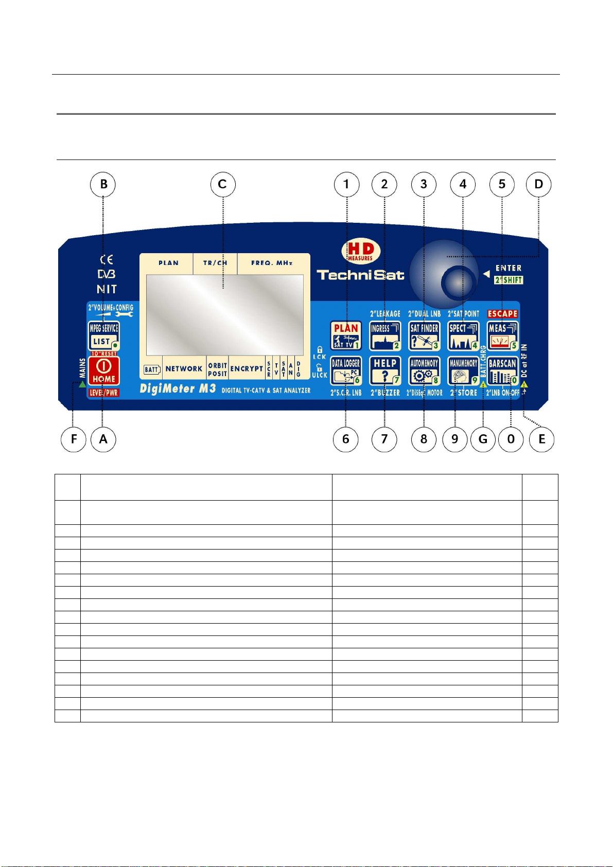
1 FRONT PANEL & KEYBOARD DESCRIPTION
A Main switch (ON/OFF) Level/Ch. Power meas. (press once)
B MPEG SERVICE LIST Setup menu configuration key .
C Graphic Display LCD
D Select (rotate) and confirm (press) Direct Frequency Input
E RF feed LED indicator
F External Power supplier/adaptor LED indicator
G Built-in battery CHARGE IN PROGRESS
1 PLAN (channel plan, memory plan) 1
2 INGRESS MODE LEAKAGE 2
3 SAT FINDER DUAL LNB 3
4 SPECT SAT POINT 4
5 MEAS (activates the measurements options) ESCAPE 5
6 DATA LOGGER S.C.R. LNB 6
7 HELP (authomatic identification of the satellite/signal) BUZZER (antenna pointing aid) 7
8 AUTOMEMORY (automatic search and storage) DiSEqC MOTOR 8
9 MANUMEMORY (manual storage) STORE 9
0 BARSCAN Enable/Disable the RF power feed 0
The keys labeled through a number can also be used for direct frequency input.
MAIN FUNCTION
SECONDARY FUNCTION
(press and hold for 2s)
RESET (press and hold for 10”)
Bloc
Num
8
Page 9
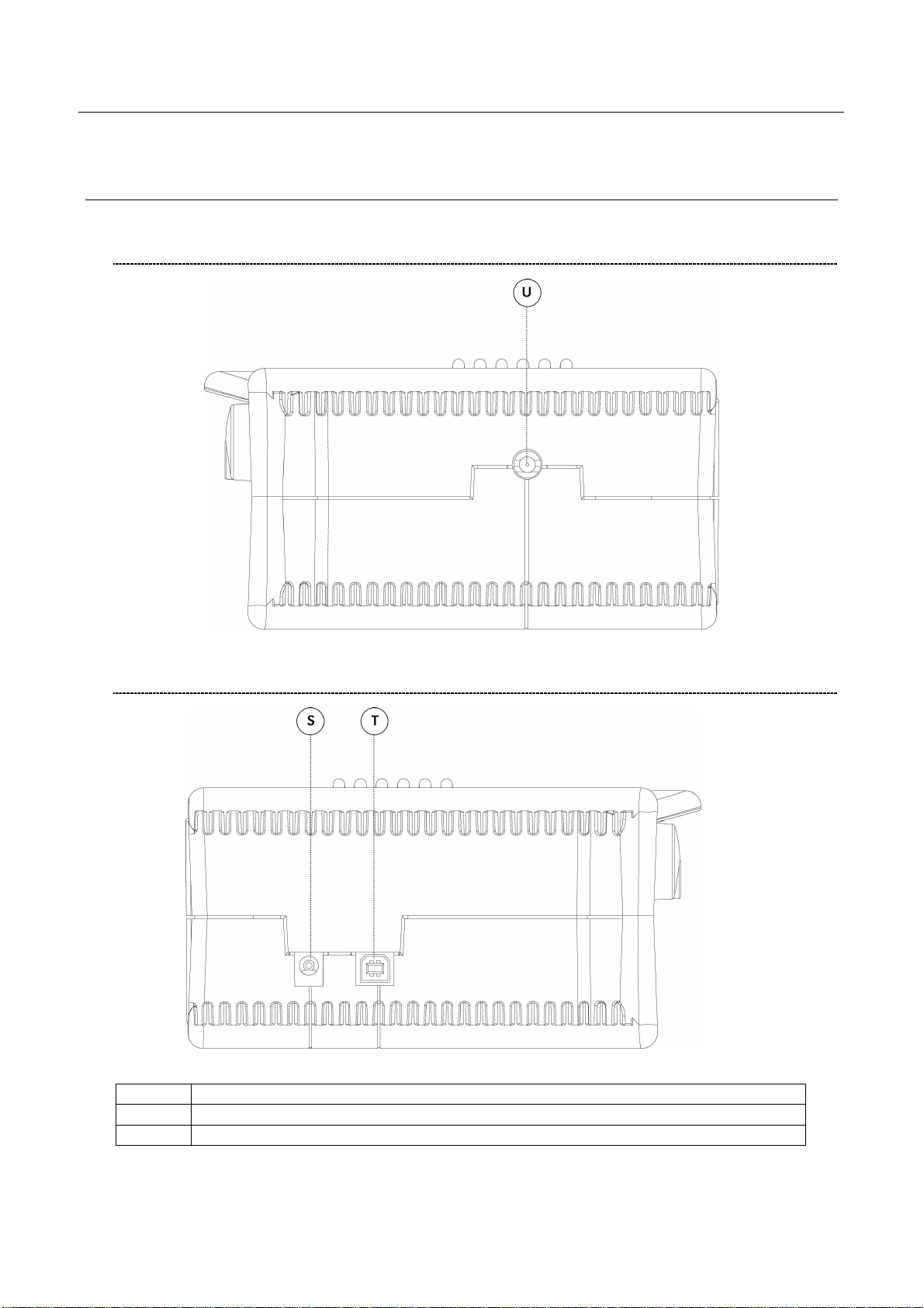
2 SIDE BODYPANELS
2.1 RIGHTSIDE BODYPANEL
DIGIMETER M3
USER MANUAL
2.2 LEFTSIDE BODYPANEL
S External power supply
T USB socket
U RF connector, type “F”, 75 ohm
9
Page 10
DIGIMETER M3
USER MANUAL
SPEEDY MEASUREMENTS ?
The DIGIMETER M3 is a really complete instrument: you will be able to perform a wide variety of
measurements on an extensive range of frequencies and of signal kinds.
This user manual will guide you throughout all the functionalities of your meter.
Should you need a brief shortcut to manage a specific kind of signal, please refer to the content of
this paragraph.
3 ONE TOUCH AND GO
3.1 ANALOGUE TV, DIGITAL (COFDM) TV AND QAM (CATV)
SIGNALS
1 Connect the signal cable to the F-type connector [U] on the meter.
2 Press once and release the PLAN [1] key. Highlight the item TELEVISION and
select the proper Country Channel Plan.
3 Press once and release the MEAS [5] key.
4 Rotate the encoder [D] to navigate the selected Country Channel Plan. The
AUTODISCOVERY ® feature will automatically detect the signal type (analogue, digital,
QAM, …) as well as the related parameters (bandwidth, symbol rate, …) and will
properly tune it.
5 Press and release the MEAS
screens. Each pulse on the MEAS [5] key will display a further measurement screen, on
a round-robin basis.
[5] key to display the various measurements
3.2 ANALOGUE SATELLITE SIGNALS, DIGITAL QPSK & 8PSK
SATELLITE SIGNALS
1 Connect the signal cable to the F-type connector [U] on the meter.
2 Press once and release the PLAN [1] key. Highlight the item SATELLITE and
select the required Satellite.
3 Press once and release the MEAS [5] key.
4 Rotate the encoder [D] to surf the various transponders of the selected satellite. The
AUTODISCOVERY ® feature will automatically detect the signal type (analogue, digital,
…) as well as the related parameters (bandwidth, symbol rate, …) and will properly tune
it.
5 Press and release the MEAS
screens. Each pulse on the MEAS [5] key will display a further measurement screen, on
a round-robin basis.
10
[5] key to display the various measurements
Page 11
DIGIMETER M3
USER MANUAL
3.3 FM / FM RADIO SIGNALS [87,5 – 108 MHz]
1 Connect the signal cable to the F-type connector [U] on the meter.
2 Press once and release the PLAN [1] key. Highlight the item MANUAL MEMORY
and select one of the MANU Memory Plans.
3 Press once and release the MEAS [5] key.
4 Rotate the encoder [D] and select a channel where no signal or an Analogue TV signal
is received.
5 Press and release repeatedly the MEAS
[5] key up to display the main Audio
peak level measurement screen.
6 Using the Standard navigation Mode, highlight the tuned signal type (TV ANALOG / TV
COFDM DVB-T/H) and select select the item FM RADIO.
7 Rotate the encoder [D] and select the desired frequency. The signal level is displayed
and the received audio signal can be listened through the meter built-in loudspeaker
3.4 SPECTRUM ANALYZER FEATURE (ANY FREQUENCY)
1 Connect the signal cable to the F-type connector [U] on the meter.
2 Tune the desired frequency (no matter if TV or Satellite).
3 Press once and release the SPECT [4] key to display the spectrum of the current
signal.
11
Page 12
DIGIMETER M3
USER MANUAL
USER MANUAL
4 TURN THE METER ON
Press and release the HOME [A] key.
5 TURN THE METER OFF
Press and hold for 2’’ the HOME [A] key.
6 CHECK THE BATTERY CHARGE STATUS
When the meter is on, at the bottom left corner of the LCD display [C] an icon will show the
current power source of the meter: built-in battery or mains external feed.
Build-in battery feed Mains external feed
Connect the supplied AC adaptor or the supplied cigarette lighter adaptor to the [S7] inlet
(located on the left side of the meter) to recharge the built-in battery. When the meter is
connected to an external power supply, the LED indicator [F] (located on the meter front
panel) turns on. When the external power connection is suitable to re-charge the build-in
battery, the LED indicator “CHARGE” [G] (located on the meter front panel) also turns on.
When the meter is off, but it is still connected to an external power supply, the built-in battery
fast charge mode is activated, and the LED indicators [F] and “CHARGE”[G] turn on brighter.
Don’t leave the instrument in LOW BATTERY conditions (1/4 charge or less) for more
than 2 months to preserve the capabilities of the built-in battery. Should the
instruments be stored for longer periods, it is required to periodically charge its
battery.
12
Page 13

DIGIMETER M3
USER MANUAL
7 THE ENCODER – STANDARD NAVIGATION MODE
Navigate into the various functions and menus of the DIGIMETER M3 is quick and easy. A
multi-function continuous encoder [D] allows the user to surf all the meter
functions, easily selecting the required function and quickly setting the desired values, by
simply rotating and pressing the encoder itself. Thanks to the ergonomic design of the
encoder knob just one hand is required.
When an item in the LCD [C] is black-highlighted, rotating the encoder [D] one step
clockwise will highlight the next item; rotating the encoder [D] one step counter-clockwise will
highlight the previous item.
Once black-highlighted the desired item, press and release the encoder knob, and the black
highlight will start blinking. When the black highlight is blinking, rotating the encoder [D] one
step clockwise will raise the value of the selected (highlighted) item; rotating the encoder [D]
one step counter-clockwise will decrease the value of the selected (highlighted) item. Once
set the appropriate value, just press and release the encoder knob, and the black highlight
will stop blinking, allowing you to move to a different item by simply rotating the encoder
knob.
These features will from now on be referred to as “Standard Navigation Mode”
13
Page 14
DIGIMETER M3
USER MANUAL
8 METER CONFIGURATION
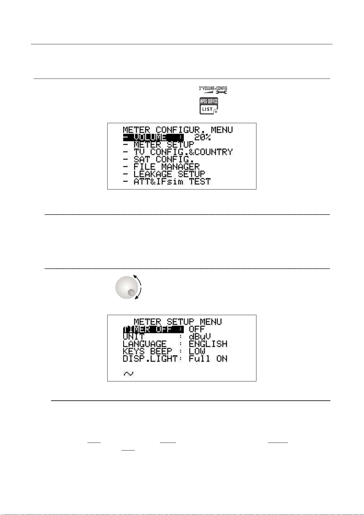
Press and hold for 2s the MPEG SERVICE LIST [B] key.
8.1 METER LOUDSPEAKER VOLUME SETUP
Using the Standard Navigation Mode, highlight the item VOLUME and adjust the volume
level of the built-in loudspeaker: you can highlight one level among: 0% (loudspeaker off),
20%, 40%, 60%, 80%, 100% (max. volume).
8.2 METER SETUP
Rotate the encoder [D] to highlight the item METER SETUP.
Press the encoder [D] to enter the meter setup menu.
BATTERY SAVING – SELF POWER OFF (TIMER OFF)
If no key of the meter is pressed within the self power off time herein sat, the meter
automatically turns itself off in order to save battery life. To set up the auto power off
time, rotate the encoder [D] to highlight the item TIMER OFF, then press it. The black
icon which highlights the item POWER OFF starts blinking. Rotate the encoder [D] and
select: OFF
off in 10 minutes). OFF (meter always on). Press the encoder [D] to enter your selection.
14
(meter always on), 5 min (meter turns off in 5 minutes), 10 min (meter turns
Page 15
DIGIMETER M3
USER MANUAL
FIELD AND CHANNEL POWER MEASUREMENT UNIT
Using the Standard Navigation Mode, highlight the item UNIT and select the requested
measurement unit: dBm, dBmV (dBmillivolt) dBuV (dBmicrovolt)
LANGUAGE
Using the Standard Navigation Mode, highlight the item LANGUAGE and select the
required language. In some releases of the meter English language only might be
available.
KEYS BEEP
Using the Standard Navigation Mode, highlight the item KEYS BEEP and select the
desired keys beep volume: OFF, LOW, MEDIUM, HIGH (max.).
DISPLAY BACKLIGHT
If no key of the meter is pressed within the backlight power off time herein sat, the
display backlight automatically turns itself off in order to save battery life.
To set up the auto backlight power off time, highlight the item DISP.LIGHT using the
Standard Navigation Mode, then select FullON (backlight always on) or 30 sec
(backlight turns off within 30 sec).
8.3 MAIN RECEPTION PARAMETER SETUP
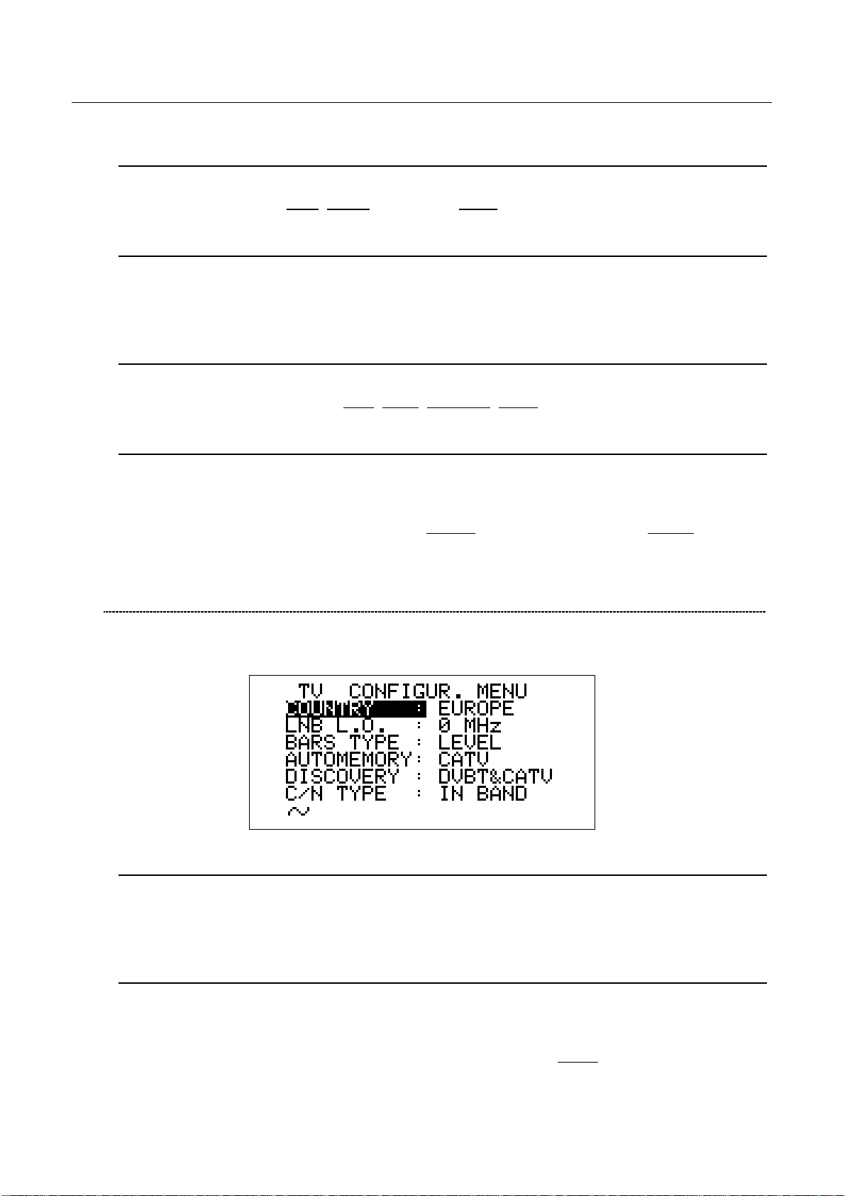
Using the Standard Navigation Mode, highlight the item TV CONFIG.& COUNTRY.
Press the encoder [D] to enter the reception parameters setup menu.
COUNTRY CHANNEL PLAN
Rotate the encoder [D] to highlight the item COUNTRY.
Press the encoder [D] once. Then, using the Standard Navigation Mode, select the
relevant Country Channel Plan (for example: ITALY)
LOCAL OSCILLATOR (FREQUENCY)
Set up the appropriate local oscillator frequency value in case a frequency conversion of
the received signals is required, .
Highlight the item LNB L.O. using the Standard Navigation Mode, then set the required
frequency (rate) of the local oscillator. The default value is 0MHz
conversion).
(no frequency
15
Page 16
DIGIMETER M3
USER MANUAL
RF INPUT SIGNAL TYPE (CABLE OR OFF AIR)
Using the Standard Navigation Mode, highlight the AUTOMEMORY item select the RF
band, terrestrial analogue and digital, (TV ONLY) or cable (CATV).
8.4 SATELLITE RECEPTION SETUP
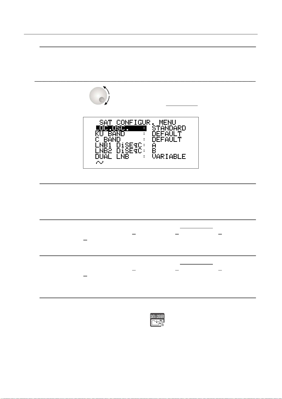
Rotate the encoder [D] to highlight the item SAT CONFIG, then press it to enter
the selection menu.
LOCAL OSCILLATOR SETUP
Using the Standard Navigation Mode, highlight the item LOC.OSC. and select
STANDARD (signal coming directly from the antenna, down-conversion required) or
0MHz(IF) (intermediate frequency signal, e.g. from a LNB).
LNB 1 ALLOWED POLARIZATION SETUP
Using the Standard Navigation Mode, highlight the item LNB1 DiSEqC and select the
required polarization for the LNB1 (A=4 polarizations, B=8 polarizations, C=12
polarizations, D=16 polarizations).
LNB 2 ALLOWED POLARIZATIONS SETUP
Using the Standard Navigation Mode, highlight the item LNB1 DiSEqC and select the
required polarization for the LNB2 (A=4 polarizations, B=8 polarizations, C=12
polarizations, D=16 polarizations).
SINGLE-CABLE SCR COMPLIANT LNB OR MULTISWITCH SETUP : SAT SCR
MENU
This function allows the user to check and manage single cable multi-users satellite
installations.
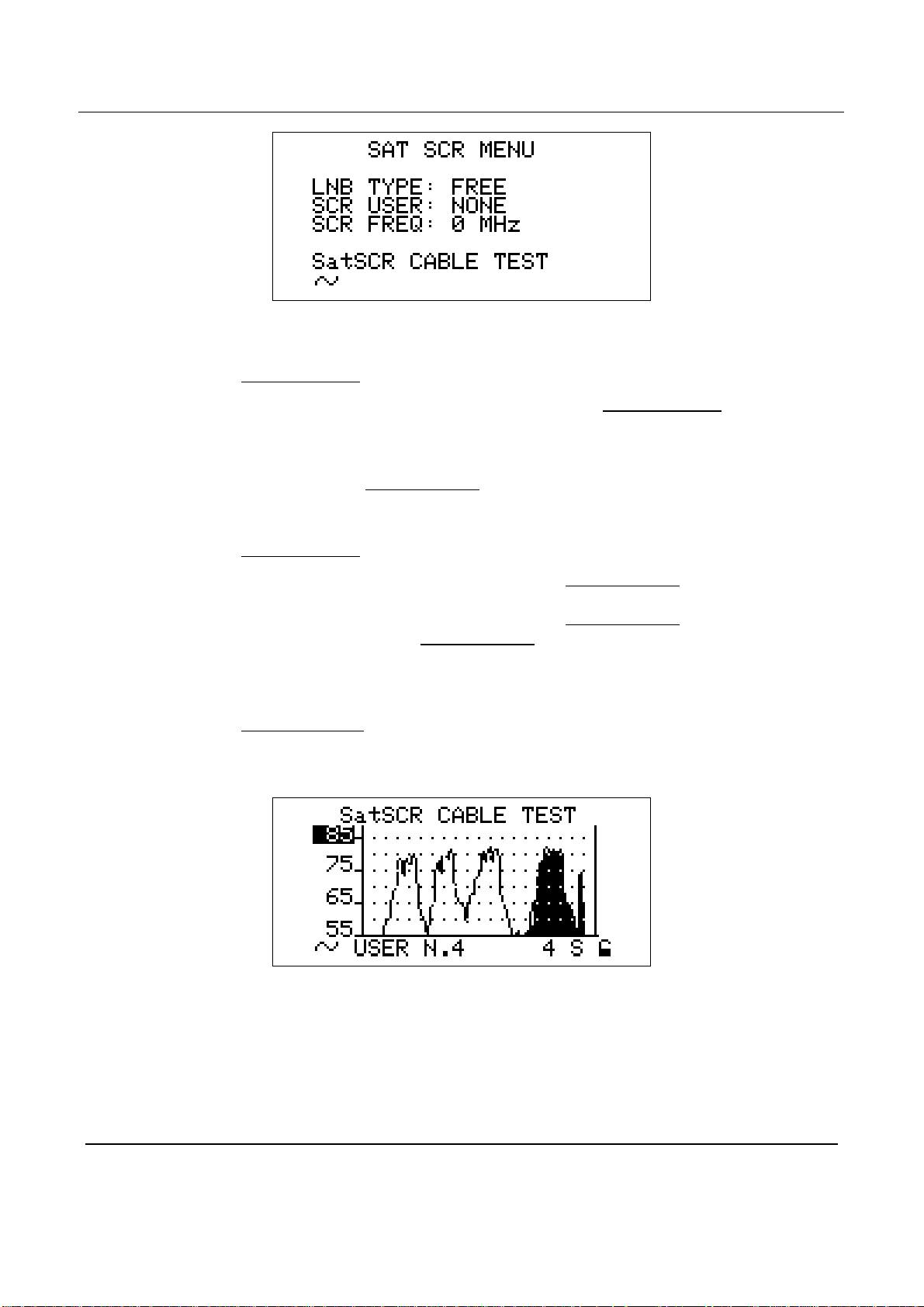
Press and hold for 2s the DATA LOGGER [6] key. The LCD [C] will display the
SAT SCR configuration menu:
16
Page 17
DIGIMETER M3
USER MANUAL
SatSCR USER:
Using the Standard Navigation Mode, highlight the item SatSCR USER. and select the
appropriate user. Up to 8 different users can be set up together with their relevant
SCR frequency value.
To manually enter each frequency value, proceed as described at paragraph SatSCR
FREQ at page 17. If the SatSCR USER item is set to NONE, it won’t be possible to set
up any frequency value.
SatSCR FREQ:
Using the Standard Navigation Mode, highlight the SatSCR USER item and select the
User whose SCR frequency value has to be set up.
Using the Standard Navigation Mode, highlight the SatSCR FREQ item and set up the
required frequency value. If the SatSCR USER item is set to NONE, it won’t be
possible to set any frequency value.
SatSCR CABLE
Using the Standard Navigation Mode, highlight the item SatSCR CABLE. Then press
the encoder [D] knob once and the LCD [C] will display:
The meter will perform the spectrum analysis for each user (from USER N.1 to USER
N.8).
The black-filled spectrum is referred to the currently selected user; the other users’
signals appears as a shape.
Using the Standard Navigation Mode, you can set up the signal level end-of-scale.
8.5 ADVANCED SETTINGS
The patented Autodiscovery feature is capable to automatically detect the standard of the
tuned signal (analogue TV, DVB-T, DVB-S, QAM, …), the relevant bandwidth as well as the
appropriate Symbol Rate (where applicable). This feature allows the user to navigate any
17
Page 18

DIGIMETER M3
USER MANUAL
frequency band by simply surfing the selected frequency band or by simply adjusting the
frequency value to be tuned; from time to time and with no action by the user required the
meter will detect the proper standard for the received signal, and will set the meter
accordingly to it, together with the appropriate measurements set.
Under rare and very critical conditions (like a co-channel interference caused on a DVB-T
signal by an analogue TV signal receivable on the same channel and with a comparable
signal strength), the Autodiscovery system could set the meter to manage the analogue
signal (the interfering one) instead of the digital one.
In these conditions it is possibile to manually select the signal standard and the relevant
measurements set.
MANUAL SIGNAL STANDARD SELECTION
Select a User Defined (MANU) Memory Plan, as described at Chapter 10.2 “NAVIGATE
INTO THE CHANNEL PLAN (USER DEFINED CHANNEL PLAN)” at page 20. Using the
Standard Navigation Mode tune the desired channel or the desired frequency value.
From the channel power (or signal level) measurement screen, using the Standard
Navigation Mode, highlight the signal standard (TV ANALOG / TV COFDM DVB-T/H /
…) and select the requested one. Then press the encoder [D] knob to enter your
selection.
Press once and release the MEAS [5] key to quit the menu.
18
Page 19

DIGIMETER M3
USER MANUAL
9 DC AT RF IN
Press and hold for 2’’ the [0] key to activate the DC AT RF IN function
When the DC power at RF in is on, the yellow led DC at RF IN [E] will be on.
WARNING: BEFORE ACTIVATING THE RF FEED, PLEASE CHECK WHETHER THE
RECEPTION SYSTEM (ANTENNA AND ACTIVE PARTS) CONNECTED TO THE METER
CAN BEAR AN RF POWER FEED.
Press and hold the BARSCAN [0] key for 2’’ to switch the DC at RF IN off. When the RF feed
is disabled, the yellow led DC at RF in [E] will be off.
19
Page 20
DIGIMETER M3
USER MANUAL
TV SIGNALS – AUDIO FM – FM RADIO SIGNALS
ANALYZER
10 SIGNAL TUNING: PLAN
Connect the signal cable to the F-type connector [U] on the meter.
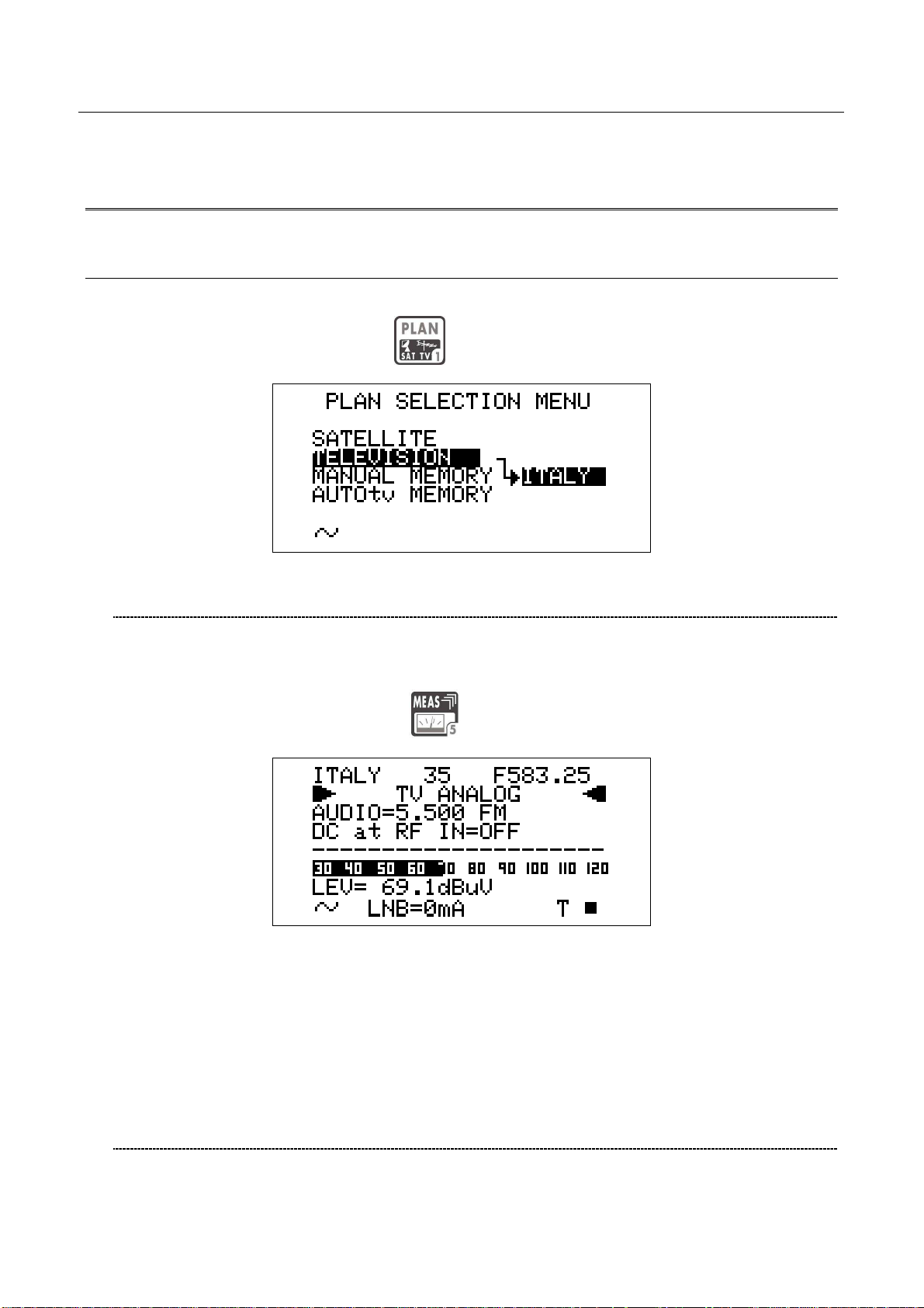
Press once and release the PLAN
[1] key.
10.1 NAVIGATE INTO THE SELECTED COUNTRY CHANNEL PLAN
Using the Standard Navigation Mode, highlight the item TELEVISION.
Check the highlighted Country Channel Plan is the required one. If not, proceed as
described in Chapter 8.3 MAIN RECEPTION PARAMETER SETUP at page 15.
Press once and release the MEAS
[5] key.
The LCD [C] top row will display (from left to right): the selected Country Channel Plan, the
channel currently tuned and the related frequency value.
Press the encoder [D] to highlight the current channel ID and rotate the encoder [D] to surf
the channels. Each step of the encoder moves the channel ID one step forward or
backward. To speed up the channel ID selection, rotate the encoder [D] continuously.
10.2 NAVIGATE INTO THE CHANNEL PLAN (USER DEFINED
CHANNEL PLAN)
To create an User Defined Channel Plan, proceed as described at Chapter 15.2
“MANUALLY CREATING A MEMORY PLAN: MANUMEMORY” at page 47 .
20
Page 21
DIGIMETER M3
USER MANUAL
Using the Standard Navigation Mode, highlight the item MANUAL MEMORY, then select
the required channels group (MANUxx plan).
Press once and release the MEAS [5] key.
The LCD [C] top row will display (from left to right): the selected channel plan, the currently
tuned channel and the corresponding frequency value.
Press the encoder [D] to highlight the current channel ID and rotate it to surf the channels
within the selected memory plan. Each step of the encoder moves the channel ID one step
forward or backward. To speed up the channel ID selection, rotate the encoder [D]
continuously.
THE METER WILL TUNE ONLY THE CHANNELS INCLUDED IN THE SELECTED
CHANNEL PLAN. To explore/navigate into a new user defined channel plan, press
once and release the PLAN key and, using the Standard Navigation Mode, highlight
the MANUAL MEMORY item to select the required channel plan.
FINE-TUNING THE FREQUENCY VALUE
Should you need to change the frequency value, using the Standard Navigation Mode
highlight the current frequency value and set the desired frequency value (Frequency
range: 45 – 878 MHz).
DIRECT FREQUENCY INPUT
Using the Standard Navigation Mode, highlight the current frequency value, and then
press and hold the encoder knob [D] for 3’’. The frequency value will be reset and a
black icon will appear to right of the “F” indicator.
This way, the BLOC NUM function is active. Enter the desired Frequency Value (in
MHz) using the numerical keys on the front panel (as described into the chart FRONT
PANEL AND KEYBOARD at page 8). To insert the comma (e.g. frequency value:
21
Page 22
839,25 MHz), press the SAT FINDER [3] key. Once entered the desired frequency
value, press the encoder knob[D] to confirm the selection.
in case the frequency value is not applicable or invalid in the TV service range (e.g.
48354 MHz), the “OUT OF RANGE” warning will be displayed and the entered value
will be voided.
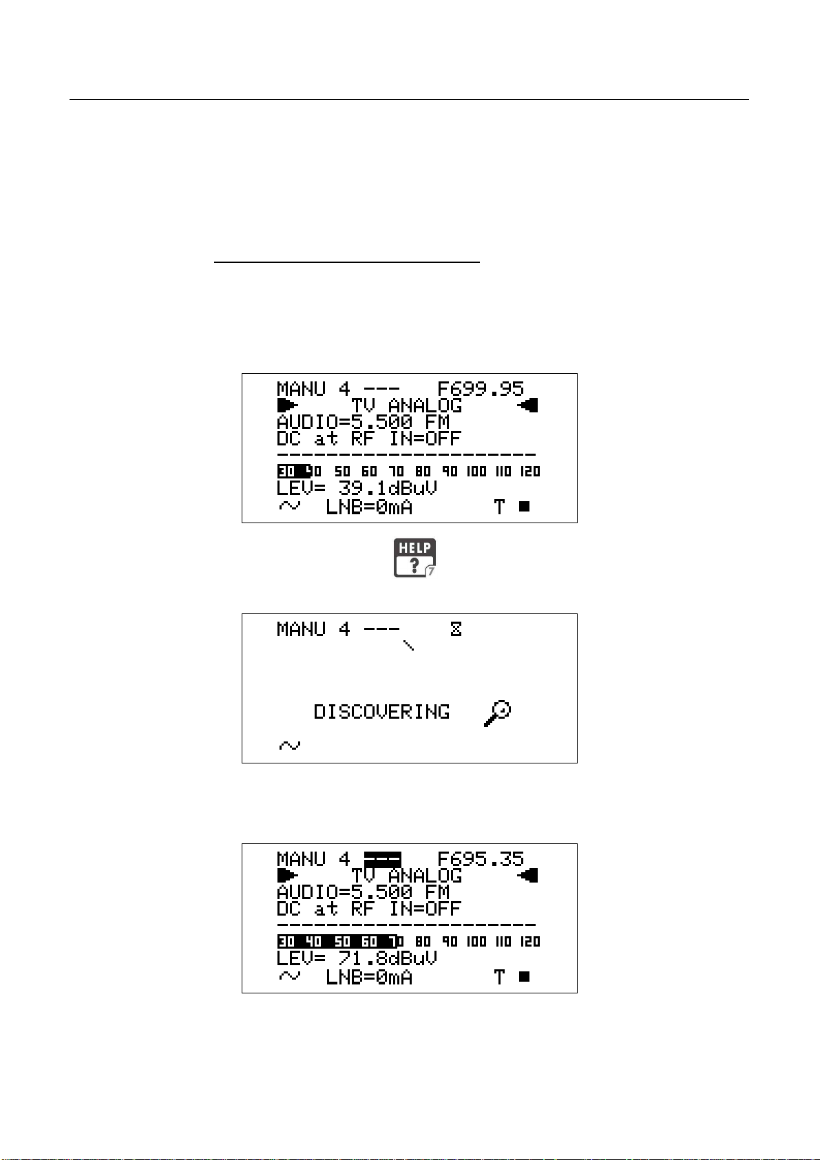
WHO IS THERE?AUTODISCOVERY ®
Once selected or fine-tuned the desired frequency value, the meter can provide the
user with the Autodiscovery ® function to self-detect and tune the received signal, both
analogue and digital, and to set the appropriate signal bandwidth.
Suppose you are starting from the frequency value 699,95 MHz, which has no
correspondence with any significant frequency value in any country channel plan:
DIGIMETER M3
USER MANUAL
Press once and release the HELP [7] key. The meter will start the
Autodiscovery ® process and will display a rotating bar as an “in progress” indicator.
When terminated, the meter displays the Autodiscovery ® results. In this case the
received signal was detected as analogue TV type at 695,35 MHz (as) video carrier
frequency.
In this case the meter was receiving an on-air analogue TV signal on EU channel 49,
thus corresponding to a 695,25 video carrier frequency. From the practical point of
view, as well as from the end user one, the meter has correctly detected the received
signal even if the start frequency (699,95) was 4,6 MHz far from the correct one.
22
Page 23
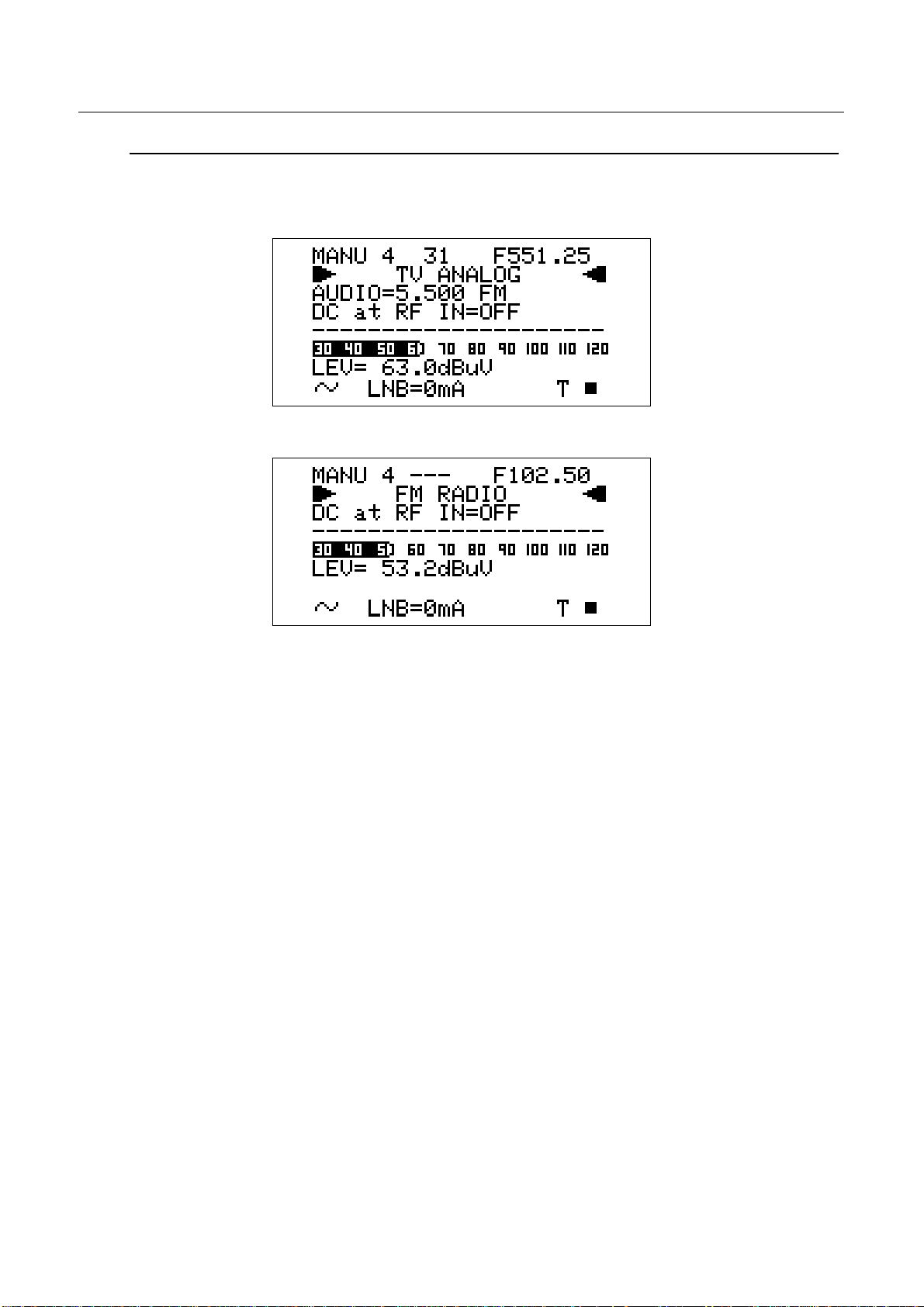
FM /FM RADIO SIGNALS TUNING [87,5 – 108 MHz]
When in the main Audio peak level measurement screen, using the Standard navigation
Mode, highlight the tuned signal type (TV ANALOG / TV COFDM DVB-T/H).
Using the encoder [D], select the item FM RADIO.
DIGIMETER M3
USER MANUAL
On the right handside of the F icon the tuned frequency is displayed, and the received
audio signal can be listened through the meter built-in loudspeaker.
Change the frequency value using the Standard Navigation Mode, or proceed as
described at page 21 DIRECT FREQUENCY INPUT
23
Page 24
DIGIMETER M3
USER MANUAL
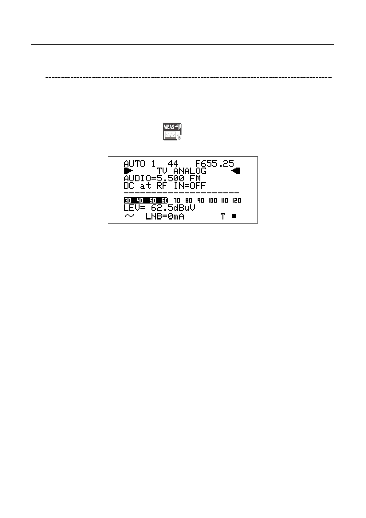
10.3 EXPLORE USER DEFINED CHANNEL
To create a channel plan (user defined list of channels), proceed as described in Chapter
15 CREATE MEMORY PLANS at page 46.
Using the Standard navigation Mode, highlight the AUTOtv MEMORY item, and press the
encoder knob [D] once. The black icon of the AUTO memory plans will start blinking. Rotate
the encoder [D] to select the required channel groups.
Press once and release the MEAS
[5] key.
Proceed as described in Chapter 10.2 NAVIGATE INTO THE CHANNEL PLAN (USER
DEFINED CHANNEL PLAN) at page 20.
24
Page 25

DIGIMETER M3
USER MANUAL
11 PERFORMING MEASURES: MEAS
The DIGIMETER M3 is equipped with one LCD [C] display; at the same time, all the
measurement values can be displayed on a high brightness screen and their reading is
immediate and intuitive, also under direct sunlight and in any weather condition.
Refer to the Chapter 10 SIGNAL TUNING: PLAN at page 20 to tune the desired channel.
11.1 THE SELECTED CHANNEL CARRIERS ON AN ANALOGUE TV
SIGNAL
VIDEO SIGNAL PEAK LEVEL MEASUREMENT
The LCD second row (from the top) displays “TV ANALOG”.
On the bottom right side of the screen, the letter “T” will be displayed above the TV icon
marked on the display frame, and a black filled quadrangle will be displayed above the AN
icon marked on the display frame.
The current video signal peak level will be displayed on the bottom of the screen, together
with the relevant measurement unit. The video signal peak level real time value is also
displayed on a level bar with peak level memory.
The last line in the display will show the video sync status.
VIDEO Vs. AUDIO PEAK LEVEL RATIO AND SIGNAL TO NOISE RATIO
From the previous measurement screen, press once and release the MEAS [5] key. The
Video Vs. Audio peak level ratio and the signal to noise ratio will be displayed.
25
Page 26

DIGIMETER M3
USER MANUAL
The meter will display the Video peak level Vs. Audio peak level Ratio (V/A, in dB) and the
Signal to Noise Ratio (C/N, in dB). Both the real time Ratios are also displayed on level bars
with peak level memory.
By repeatedly pressing and releasing the MEAS [5] key the above mentioned
screens will appear in sequence. Press once and release the [A] key once to
directly enter the Video signal peak level measurement.
SPECTRUM ANALYSIS OF THE TUNED CHANNEL
Proceed as described in Chapter 12 SPECTRUM ANALYZER MODEat page 38.
26
Page 27

DIGIMETER M3
USER MANUAL
11.2 THE SELECTED CHANNEL CARRIERS ON A DTT (COFDM)
SIGNAL
THE CHANNEL IS SUCCESSFULLY LOCKED (THE LOCK ON THE LCD
BOTTOM-RIGHT CORNER IS CLOSED)
NOISE MARGIN, QUALITY TEST, MER AND ERROR COUNT
MEASUREMENTS
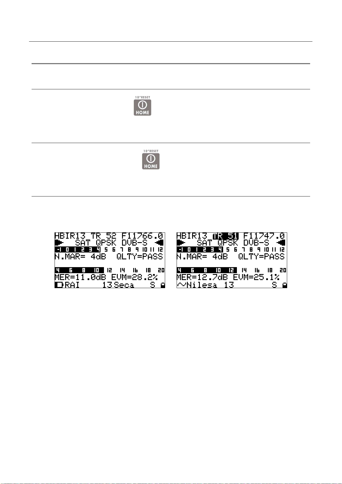
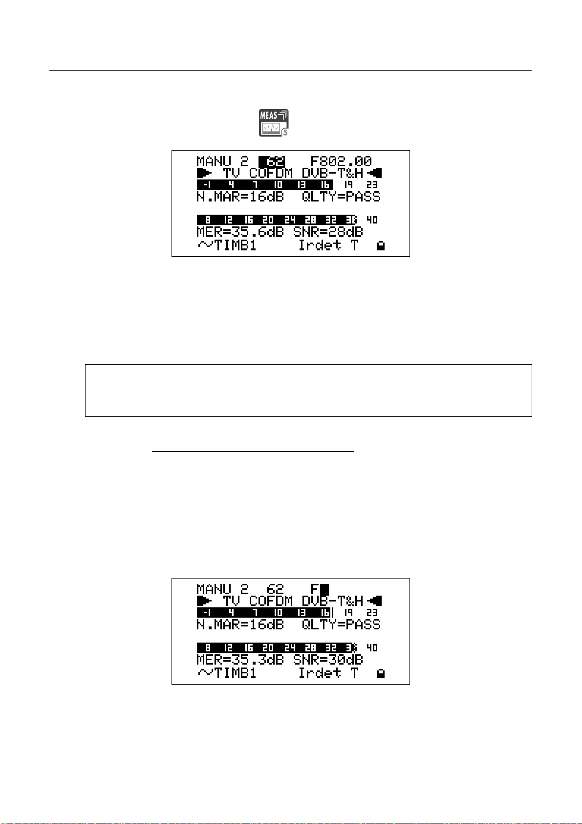
The second row of the LCD [C] displays TV COFDM DVB-T&H.
When the channel is properly locked, the first screen of the meter shows the Noise Margin
value (N.MARG), the result of the real time quality test (QLTY, FAIL, MARG. and PASS), and
the MER and ERROR COUNT measurements. The Noise Margin and the MER
measurements are also displayed on level bars with peak level memory.
Furthermore, the bottom row of the LCD will display the main information of the tuned
bouquet:
• Bouquet name (network name), after some seconds and under acceptable
receiving conditions.
• Encryption system (encrypt), if there is at least one encrypted program in the
bouquet, after some seconds and in acceptable receiving conditions.
• T, above the TV icon on the LCD [C] frame
• A closed lock in the bottom right corner of the LCD [C]
BER MEASUREMENTS BEFORE AND AFTER ERROR CORRECTION
VITERBI
From the previous measurement screen, press once and release the MEAS [5] key
once. The BER before Viterbi error correction (in this meter labeled as bBER or preBER) and
the BER after Viterbi error correction (in this meter labeled as aBER or posBER) parameters
will be displayed.
27
Page 28

These measurements are also displayed on a level bar with peak level memory.
CONSTELLATION CHART AND OFDM PARAMETER
From the previous measurement screen, press once and release the MEAS [5] key.
The constellation will be displayed together with the following parameters:
DIGIMETER M3
USER MANUAL
• Bandwidth of the tuned signal (COFDM)
• Modulation / Order of QAM (MODE)
• Number of Carries and modulation system (CARR)
• Guard Interval (G.INT)
• High and Low Priority stream code rate (HP / LP)
• Hierarchic modulation mode active (HIER)
This meter allows to zoom-in the upper-right quadrant of the constellation chart.
Using the Standard Navigation Mode, highlight the ZOOM item and select the zoom
level: just the upper-right quadrant of the complete constellation (both I and Q
positive), the top right section of the first quadrant, or the whole constellation chart.
28
Page 29

DIGIMETER M3
USER MANUAL
IMPULSE RESPONSE OF THE SELECTED CHANNEL
From the previous measurement screen, press once and release the MEAS [5] key.
The impulse response of the tuned channel will be displayed.
The meter assumes as main signal (i.e. the signal with zero delay) the “echo” with the
highest level among all the detected signals.
To tune a different channel, using the Standard Navigation Mode, highlight the
channel ID item and select the required channel.
WARNING: only the channels included into the Channels Plan (PLAN) in use will be
displayed.
Refer to Chapter 10 SIGNAL TUNING: PLAN at page 20
To switch from the time to space domain for the echoes measurement, using the
Standard Navigation Mode highlight the (DIST or TIME) item at the top of the vertical
axis and select the required domain. To change the marker position, using the
Standard Navigation Mode highlight the echoes position item located at the top right
side of the display and sweep the marker position. The current marker position is
shown on the display through a vertical dotted row.
The marker can also be moved in the negative portion of the selected domain (both
time and space). Into the negative portion the echoes:
• occurring before the main signal (PRE ECHOES) and
• whose level is below the main signal level
can be found.
BOUQUET DATA ID
From the previous measurement screen, press once and release the MEAS [5] key.
29
Page 30

In case the tuned bouquet contains the relevant information, the LCD will display:
• the network name (NETW. NAME)
• the bouquet name (BOUQ. NAME)
• the current date (DATE), as stated in the bouquet itself
• the signal / noise ratio (SNR)
Any information missing not included in the bouquet will result in a blank field. Anyway,
the signal is properly locked even when one or all of said information is missing provided
that the lock at the LCD bottom right corner is closed.
DIGIMETER M3
USER MANUAL
CHANNEL POWER MEASUREMENT
From the previous measurement screen, either Press once and release the MEAS
[5] key once or
under any circumstance press the HOME [A] key once to enter the channel power
measurement.
On the LCD bottom row, the channel power measurement, together with the
relevant measurement unit will be displayed. This real time value is also displayed
on a level bar with peak level memory.
WHILE PERFORMING SUCH MEASUREMENTS, THE LOCK DISPLAYED AT
BOTTOM RIGHT SIDE OF THE SCREEN WILL BE OPEN. THIS IS BECAUSE THE
METER EXPLORES THE WHOLE CHANNEL BAND IN ORDER TO DETECT THE
TRUE CHANNELPOWER.
However in the following measurement screens, the signal will be displayed as correctly locked.
All the six measurements screens above described, and related to DTT (COFDM) signals
will be cyclically displayed by repeatedly pressing the MEAS
[5] key.
30
Page 31

DIGIMETER M3
USER MANUAL
Press once and release the HOME [A] key to directly switch to the channel power
measurement.
DISPLAYING THE SERVICE LIST OF THE CURRENT BOUQUET
Press once and release the MPEG SERVICE LIST [B] key once.
The LCD [C] will display:
• the full program list of the currently tuned bouquet;
• the relevant video (Vpid) and audio (Apid) PIDs, and
• the encryption status key (Y= encrypted, N= not encrypted/free to air).
It might take few second to get the full information displayed.
Rotate the encoder [D] to scroll down the program list (up to 64).
Press once and release the MEAS [5] key to quit to the previous measurement screen.
BUZZER FUNCTION (ASSISTED ANTENNA ALIGNMENT)
Press and hold for 2’’ the HELP
[7] key. You can hear a beep whose duty
cycle is proportionally to the signal Noise Margin.
This is an antenna alignment aid feature. The buzzer tone can be activated only when
the received digital signal is correctly locked. The LCD [C] will display:
The LCD [C] second row shows (from the left): the memory plan in use, the currently
tuned channel ID and the relevant frequency value. The frequency value can be
changed using the Standard Navigation Mode.
The bottom section of the display shows the Noise Margin measurement (also on a
level bar with peak memory display) and the result of the signal quality test (PASS,
MARGINAL, FAIL).
Press any key to deactivate the buzzer tone and to quit this function.
31
Page 32

WARNING: the buzzer function is active only with digital signals.
SPECTRUM ANALYZER MODE
Proceed as described in Chapter 12 SPECTRUM ANALYZER MODEat page 38.
THE CHANNEL IS NOT SUCCESSFULLY LOCKED (THE LOCK ON THE LCD
BOTTOM-RIGHT CORNER IS OPEN)
The meter will display as first measurement screen the channel power measurement (see
the Chapter CHANNEL POWER MEASUREMENT at page 35).
The further measurement screens, related to DTT (COFDM) signals will be cyclically
DIGIMETER M3
USER MANUAL
It cannot be activated for analogue signals
displayed by repeatedly pressing the MEAS [5] key.
From any measurement screen press once and release the HOME [A] key to
directly perform the channel power measurement.
32
Page 33

DIGIMETER M3
USER MANUAL
11.3 THE SELECTED CHANNEL CARRIES ON A QAM (CATV) SIGNAL
THE CHANNEL IS SUCCESSFULLY LOCKED (THE LOCK ON THE LCD
BOTTOM-RIGHT CORNER IS CLOSED)
The Autodiscovery will automatically detect the QAM signal type. The second row of the
LCD [C] displays TV QAM, together with the relevant standard (e.g.: DVB-C).
NOISE MARGIN, QUALITY TEST, MER AND ERROR COUNT
MEASUREMENTS
The second row of the LCD [C] displays TV QAM and the relevant standard.
When the channel is properly locked, the first screen of the meter shows the Noise Margin
value (N.MARG), the result of the real time quality test (QLTY, FAIL, MARG. and PASS),
and the MER and ERROR COUNT (ERRORS) measurements. The Noise Margin and the
MER measurements are also displayed on level bars with peak level memory.
Furthermore, the bottom row of the LCD will display the main information of the tuned
bouquet:
• Bouquet name (network name), after some seconds and under acceptable
receiving conditions.
• Encryption system (encrypt), if there is at least one encrypted program in the
bouquet, after some seconds and in acceptable receiving conditions.
• C, above the TV icon on the LCD [C] frame
• A closed lock in the bottom right corner of the LCD [C]
BER MEASUREMENTS BEFORE AND AFTER VITERBI ERROR
CORRECTION
33
Page 34

From the previous measurement screen, press once and release the MEAS [5] key
once. The BER before Viterbi error correction (in this meter labeled as bBER or
preBER) and the BER after Viterbi error correction (in this meter labeled as aBER or
posBER) parameters will be displayed.
These measurements are also displayed on a level bar with peak level memory.
CONSTELLATION CHART AND QAM PARAMETER
DIGIMETER M3
USER MANUAL
From the previous measurement screen, press once and release the MEAS [5] key.
The constellation will be displayed together with the following parameters:
• The broadcasting standard of the tuned signal (Annex)
• The QAM modulation mode (MODE)
• The signal Symbol Rate (SR)
This meter allows to zoom-in the upper-right quadrant of the constellation chart.
Using the Standard Navigation Mode, highlight the ZOOM item and select the zoom
level: just the upper-right quadrant of the complete constellation (both I and Q
positive), the top right section of the first quadrant, or the whole constellation chart.
34
Page 35

DIGIMETER M3
USER MANUAL
BOUQUET DATA ID
From the previous measurement screen, press once and release the MEAS [5] key.
In case the tuned bouquet contains the relevant information, the LCD will display:
• the network name (NETW. NAME)
• the bouquet name (BOUQ. NAME)
• the current date (DATE), as stated in the bouquet itself
Any information missing not included in the bouquet will result in a blank field. Anyway, the
signal is properly locked even when one or all of said information is missing provided that
the lock at the LCD bottom right corner is closed.
CHANNEL POWER MEASUREMENT
From the previous measurement screen, either Press once and release the MEAS [5]
key once or under any circumstance press the HOME [A] key once to enter the
channel power measurement.
On the LCD bottom row, the channel power measurement, together with the relevant
measurement unit will be displayed. This real time value is also displayed on a level
bar with peak level memory.
WHILE PERFORMING SUCH MEASUREMENTS, THE LOCK DISPLAYED AT BOTTOM
RIGHT SIDE OF THE SCREEN WILL BE OPEN. THIS IS BECAUSE THE METER
EXPLORES THE WHOLE CHANNEL BAND IN ORDER TO DETECT THE TRUE
CHANNELPOWER.
35
Page 36

From the previous measurement screen, either Press once and release the MEAS [5]
key once or under any circumstance press the HOME [A] key once to enter the
channel power measurement.
DIGIMETER M3
USER MANUAL
On the LCD bottom row, the channel power measurement, together with the relevant
measurement unit will be displayed. This real time value is also displayed on a level
bar with peak level memory.
WHILE PERFORMING SUCH MEASUREMENTS, THE LOCK DISPLAYED AT BOTTOM
RIGHT SIDE OF THE SCREEN WILL BE OPEN. THIS IS BECAUSE THE METER
EXPLORES THE WHOLE CHANNEL BAND IN ORDER TO DETECT THE TRUE
CHANNELPOWER.
However in the next measurement screens, the signal will be displayed as correctly
locked.
All the various measurements screens above described, and related to QAM (CATV) signals will
be cyclically displayed by repeatedly pressing the MEAS [5] key. Press once and release
the HOME
[A] key to directly switch to the channel power measurement.
36
Page 37

DIGIMETER M3
USER MANUAL
DISPLAYING THE SERVICE LIST OF THE CURRENT BOUQUET
Press once and release the MPEG SERVICE LIST [B] key once.
The LCD [C] will display:
• the full program list of the currently tuned bouquet;
• the relevant video (Vpid) and audio (Apid) PIDs, and
• the encryption status key (Y= encrypted, N= not encrypted/free to air).
It might take few second to get the full information displayed.
Rotate the encoder [D] to scroll down the program list (up to 64).
Press once and release the MEAS [5] key to quit to the previous measurement screen.
SPECTRUM ANALYZER MODE
Proceed as described in Chapter 12 SPECTRUM ANALYZER MODE at page 38.
THE CHANNEL IS NOT SUCCESSFULLY LOCKED (THE LOCK ON THE LCD
BOTTOM-RIGHT CORNER IS OPEN)
The meter will display as first measurement screen the channel power measurement (see
the Chapter CHANNEL POWER MEASUREMENT at page 35).
The further measurement screens, related to DTT (COFDM) signals will be cyclically
displayed by repeatedly pressing the MEAS [5] key.
From any measurement screen press once and release the HOME [A] key to
directly perform the channel power measurement
37
Page 38

DIGIMETER M3
USER MANUAL
12 SPECTRUM ANALYZER MODE
Press once and release the SPECT [4] key to display the spectrum of the current
signal.
In case the tuned signal is analogue, the marker will be positioned by default on the
frequency value corresponding to the analogue Video signal peak level. The relevant level is
displayed in the LCD bottom row (MRK
), together with the relevant measurement unit.
12.1 SURFING THE CHANNELS
Using the Standard Navigation Mode, highlight the currently tuned channel ID, then select
the desired channel ID.
WARNING: only the channels included into the channel plan (PLAN) currently in use
will be displayed.
Refer to Chapter 10 SIGNAL TUNING: PLAN at page 20
12.2 MOVING THE MARKER (FREQUENCY VALUE)
Using the Standard Navigation Mode, highlight the frequency item, then move the marker
position (current frequency value).
The meter LCD will at any time display the current frequency value (first row, top right) and
the relevant signal level measurement (bottom row, MRK
38
).
Page 39

DIGIMETER M3
USER MANUAL
12.3 EDITING THE SIGNAL LEVEL END OF SCALE
Using the Standard Navigation Mode, highlight the top level (end of scale) value on the yaxis, then select the desired end of scale value.
12.4 EDITING THE SPAN VALUE
Using the Standard Navigation Mode, highlight the span (SP) value. Then select the
desired span value. Only pre-defined span values (from 2 MHz to FULL) can be set. No fine
adjustment is possible.
12.5 ACTIVATE THE MAX HOLD FUNCTION
Press once and release the SPECT [4] key. The MaxH icon will be displayed on the bottom
row in correspondence with the “ENCRYPT” item on the right edge of the display. Press
once and release the SPECT [4] key again to quit the MaxHold function.
12.6 FULL BAND MAPPING
The meter can display a bar diagram in which each bar displays the signal level detected
on a specific channel into the whole selected frequency band. The bar diagram, the marker,
and the display bottom row can display several parameters, depending on the meter
configuration.
FULL BAND MAPPING DISPLAY CONFIGURATION
Press and hold for 2’’ the MPEG SERVICE LIST [B] key. Using the Standard Navigation
Mode, highlight the TV CONFIG.& COUNTRY item, then press the encoder knob to
enter the configuration menu. Using the Standard Navigation Mode, highlight the BARS
TYPE item and select the required display mode as described below.
SIGNAL LEVEL / CHANNEL POWER DETECTED INTO EACH CHANNEL
(BARSCAN)
Using the Standard Navigation Mode, select the LEVEL item. Each bar will display the
real time video signal peak level (analogue signals) or the real time channel power
(digital signals) detected in the corresponding frequency channel.
AUDIO AND VIDEO PEAK LEVEL DETECTED INTO EACH CHANNEL
Using the Standard Navigation Mode, select AUD/LEV. Each bar will display at the
same time the real time audio peak level and the real time video peak level measured
in the corresponding channel. This display mode make sense only when performed on
analogue signals.
SIGNAL LEVEL COMPARISON (TILT) BETWEEN TWO USERS-DEFINED
CHANNEL
Using the Standard Navigation Mode, select TILT. The meter will display the signal
level difference between two user-defined channels. These two channels can be
39
Page 40

DIGIMETER M3
USER MANUAL
directly set while this measurement function is active.
ACTIVATE THE FULL BAND MAPPING
Select one channel ID in the band (VHF, UHF, or CATV) to be analyzed (refer to
Chapter 12.1 SURFING THE CHANNELS at page 38.
Press once and release the BARSCAN [0] key. Depending on the selected
configuration a specific bar diagram will be displayed.
FULL BAND SIGNAL LEVEL ANALYSIS IN EACH CHANNEL (LEVEL)
The marker (the vertical dotted line) is positioned on the channel which is currently
displayed in the centre field of the LCD top row and whose frequency is displayed in
the LCD top right edge. The LCD bottom row displays the signal level measured in the
currently selected channel (MRK) together with the measurement unit currently set for
the meter. An horizontal dotted line shows the real time signal level value measured in
the currently selected channel.
FULL BAND AUDIO AND VIDEO PEAK LEVEL ANALYSYS INTO EACH
CHANNEL (AUD/VID)
Each black bar will contain a white pixel in it.
The overall height of each bar displays the video peak level measured in the relevant
channel.
The height of the bar segment between the x-axis and the above white pixel displays
the audio peak level measured in the relevant channel.
The marker (the vertical dotted line) is positioned on the channel which is currently
displayed in the centre field of the LCD top row and whose frequency is displayed in
40
Page 41

DIGIMETER M3
USER MANUAL
the LCD top right edge. The LCD bottom row displays the video peak level measured
in the currently selected channel (MRK) together with the measurement unit currently
set for the meter. An horizontal dotted line shows the real time video peak level
measured in the currently selected channel.
This measure makes sense when performed on analogue signals only.
FULL BAND SIGNAL LEVEL COMPARISON BETWEEN TWO USER-
DEFINED CHANNELS (TILT)
Two triangle - shaped markers on the x-axis locate the two channels whose signal
level is under comparison.
Each bar displays the signal level measured in the relevant channel.
The LCD top row displays the two channels (1: and 2:) whose signal level has to be
compared. The LCD bottom row displays (TLT, tilt) the difference between the signal
level value measured in channel 1: and the one measured in channel 2:.
To select the channels whose signal level has to be compared, using the Standard
Navigation Mode highlight the channel (1:A; 2:F) to be edited. Then rotate the encoder
[D] to select the desired channel.
41
Page 42

DIGIMETER M3
USER MANUAL
QAM CATV SIGNAL ANALYZER
13 TUNING QAM CATV SIGNALS
The patented Autodiscovery feature is capable to automatically detect both the modulation
type and the standard of the received signal. Thus no need for the user to operate any specific
setup in order to perform measurements on CATV signals, both analogue and digital (QAM)
ones.
To perform measurements on QAM signals just procede as described in Chapter 0 “
THE SELECTED CHANNEL CARRIES ON A QAM (CATV) SIGNAL
” at page 33.
14 CABLE SYSTEM MEASUREMENTS
14.1 INGRESS MODE (MEASUREMENTS ON THE FREQUENCY
RANGE 4 ÷ 66 MHz)
Press and release the INGRESS [2] key to enter the Ingress Mode.
The LCD will display the real time spectrum monitoring in the frequency band 4 ÷ 66 MHz.
A dotted vertical line (marker) displays the frequency value whose signal level is currently
displayed in the LCD bottom row (MRK) together with the relevant measurement unit. In the
top right edge the LCD displays frequency value corresponding to the current marker position
(F, highlighted in the above screenshot, in MHz) An horizontal dotted line shows the real time
signal level value at the current marker position (current frequency value).
MOVING THE MARKER (FREQUENCY VALUE)
Using the standard navigation mode, highlight the current frequency value and modify the
marker position (current frequency value). The meter displays will at any time display the
current frequency value (first row, top right) and the relevant signal level measurement
(bottom row, MRK
specific frequency using the Direct Frequency input
42
). Please note: while in INGRESS Mode you cannot set up a
Page 43

DIGIMETER M3
USER MANUAL
EDITING THE SWEEP TIME
Using the standard navigation mode, highlight the sweep time on the display top left
corner of the y-axis. and select the desired sweep time. Only pre-defined sweep times
(from 50 ms to 50 s) can be set.
EDITING THE END-OF-SCALE VALUE
Using the standard navigation mode, highlight the end-of-scale value and select the
desired value
SETTING THE START FREQUENCY AND THE STOP FREQUENCY IN INGRESS
MODE
Once entered the INGRESS MODE, press and release the INGRESS [2] key.
SETTING THE START FREQUENCY
Using the Standard navigation mode, highlight the Start F.: item and set the desired
Start Frequency value.
SETTING THE STOP FREQUENCY
Using the Standard navigation mode, highlight the Stop F.: item and set the desired
Stop Frequency value.
INGRESS MODE MAX HOLD ON/OFF
Using the Standard Navigation Mode, highlight the Hold item and select Enable or
Disable.
Press once and release the INGRESS [2] key to return to the INGRESS MODE.
14.2 CABLE LEAKAGE MEASUREMENTS
LEAKAGE SETUP
Press and hold for at least two seconds the MPEG SERVICE LIST [B] key. Using the
Standard Navigation Mode highlight the LEAKAGE SETUP item and press the encoder
[D] knob to enter the setup menu.
Press once and release the MEAS [5] key to quit the CABLE LEAKAGE setup menu.
43
Page 44

AREA AND MEASUREMENT UNIT STANDARD SETUP
Using the Standard Navigation Mode highlight the field AREA and select the
appropriate area. The meter will then accordingly set the appropriate measurement
units and antenna sets
ANTENNA TYPE SETUP (USA ONLY)
Using the Standard Navigation Mode highlight the field ANT.TYPE and select the
appropriate antenna type in use.
DIGIMETER M3
USER MANUAL
ANTENNA FACTOR SETUP
Using the Standard Navigation Mode highlight the field ANT.FACT. and select the
appropriate antenna factor.
DISTANCE SETUP
Using the Standard Navigation Mode highlight the field DISTANCE and set the
appropriate distance according to the cable network on test.
THRESHOLD SETUP
Using the Standard Navigation Mode highlight the field THRESH and set up the
appropriate threshold value expressed in the measurement unit which is currently
displayed by the meter.
PERFORMING CABLE LEAKAGE MEASUREMENTS
Press and hold for at least 2s the INGRESS [2] key to activate a cable leakage
measurement session using the parameters set up as per Chapter LEAKAGE SETUP at
page 43.
44
Page 45

DIGIMETER M3
USER MANUAL
Use the Standard Navigation Mode to edit the test frequency. The meter will display
both the real time cable leakage factor (LIVE VAL) and the maximum leakage factor
detected during the same measurement session (PEAK VAL). A measurement session
does NOT get stopped when editing the test frequency, therefore the PEAK VAL
displays the maximum value of the cable leakage factor detected by the meter on all the
test frequencies set on the meter by the user while performing the same measurement
session.
Press and release the MEAS [5] key o stop the current measurement session; this will
also quit the Cable Leakage measurement.
45
Page 46

DIGIMETER M3
USER MANUAL
MEMORY FEATURES FOR TV (ANALOGUE, COFDM,
QAM) AND FM RADIO SIGNALS
15 CREATE MEMORY PLANS
15.1 CREATING A MEMORY PLAN BY AUTO SEEK & STORE OF ANY
RECEIVABLE CHANNEL: AUTOSCAN
Press once and release the AUTOMEMORY [8] key.
SELECT A TARGET AUTOMEMORY CHANNEL PLAN
The target destination plan is the channel plan where the result of the seek&store
operation will be stored.
Right to the DESTINAT. item, the name of the current target automemory plan is
displayed. If the current target plan is void, the LCD bottom row will display START?. In
case the current target plan already exists and contains data, the LCD bottom row will
display OVERWRITE?.
Using the Standard Navigation Mode, highlight the DESTINAT. item and select the
desired target Automemory channel plan (AUTO 1, AUTO 2, …).
ANALOGUE SIGNALS: VIDEO SIGNAL LEVEL THRESHOLD SETUP
Using the Standard Navigation Mode, highlight the LEVEL item and set the video level
threshold. Only the channels whose video signal level is above this threshold will be
saved to the target Automemory plan.
DIGITAL SIGNALS: CHANNEL POWER LEVEL THRESHOLD SETUP
Using the Standard Navigation Mode, highlight the POWER L item and set the channel
power threshold. Only the channels whose channel power is above this threshold will
be saved to the target Automemory plan.
SEEK&STORE (SCAN) START
Using the Standard Navigation Mode, highlight the display bottom row.
46
Page 47

DIGIMETER M3
USER MANUAL
If START? appears a brand new memory plan will be stored. Should OVERWRITE?
appear, the selected target Automemory plan already contains data, and will be
overwritten without further notice.
Press the encoder [D] knob once and the auto seek & store will start. The display will
also give information on the status of the research. When finished, the total number of
both analogue and digital found and stored channels will be displayed.
15.2 MANUALLY CREATING A MEMORY PLAN: MANUMEMORY
Press and release the MANUMEMORY [9] key.
CREATE A BRAND NEW MEMORY PLAN
Using the Standard Navigation Mode, highlight the MANUxx item of the LCD display top
row on the left and select the desired target memory plan. When the current target plan
is void, the LCD row under the dotted line bottom row displays MEM P1: ---.
• Select a void memory plan (the LCD row under the dotted line bottom row displays
MEM P1: ---)
• Using the Standard Navigation Mode, highlight the channel ID item in the first row of
the LCD display. Then select the channel ID to be stored into the target memory
plan.
• Using the Standard Navigation Mode, highlight the SAVE? item.
• Press the encoder knob. The selected channel will be stored.
To add further channels to the current memory plan:
• Using the Standard Navigation Mode, highlight the channel ID item in the first row of
the LCD display. Then select the new channel ID to be stored.
• Using the Standard Navigation Mode, highlight the MEM..:P item, and select a void
memory position (the LCD row under the dotted line will displays, e.g. MEM: P 5: ---).
• Highlight the SAVE? item.
• Press the knob. The selected channel has now been stored.
Press once and release the MEAS [5] key to quit the memory menu.
ADDING A FURTHER CHANNEL TO AN EXISTING MEMORY PLAN
Using the Standard navigation Mode, highlight the MANUxx item in the LCD top row on
the left, then select the desired target memory plan (in which a new channel has to be
added). Then:
• Using the Standard navigation Mode, highlight the channel ID item on the first row of
the display and select a new channel ID to be stored.
47
Page 48

DIGIMETER M3
USER MANUAL
• Highlight the MEM..:P item, and select a void memory position (the first LCD row
under the dotted line displays, e.g., MEM: P 6: ---).
• Highlight the SAVE? Item and press the encoder knob. The selected channel ID has
now been stored.
Further channels may be added by repeating the above steps.
Press once and release the MEAS [5] key to quit this menu.
ADDING A FURTHER CHANNEL TO A MEMORY PLAN CURRENTLY IN USE
When the channel ID to be added to the memory plan in use is already correctly tuned
(proceed as described in Chapter 10 SIGNAL TUNING: PLAN at page 20), press and
hold for 2’’ the MANUMEMORY [9] key.
The tuned channel will be automatically stored in the first void position of the current
memory plan. The LCD [C] will display:
Press and release the MEAS [5] key to quit this menu.
15.3 DELETING A MEMORY PLAN
Press and hold for 2s the MPEG SERVICE LIST [B] key. Using the Standard navigation
Mode, highlight the FILE MANAGER item, then press the encoder knob [D] to enter the
configuration menu.
THE MEMORY PLAN CURRENTLY IN USE CANNOT BE DELETED.
To change the memory plan currently in use, proceed as described in Chapter 10 SIGNAL
TUNING: PLAN at page 20.
DELETING AN AUTOMEMORY CHANNEL PLAN
Using the Standard navigation Mode, highlight the SELECT TYPE item and select
AUTOSCAN.
48
Page 49

• Using the Standard navigation Mode, highlight SELECT FILE and select the memory
plan to be deleted (AUTO 1, AUTO 2, …).
• Highlight the item DELETE FILE and press the encoder knob [D] to permanently
delete the above selected memory plan.
The meter will confirm the selected plan has been deleted (DELETED!). The warning
message VOIDED! means you have tried to delete a permanent and not erasable
memory plan (e.g.: ITALY).
DELETING A MANUAL MEMORY CHANNEL PLAN
Using the Standard navigation Mode, highlight the item SELECT TYPE, then select the
item PLAN.
DIGIMETER M3
USER MANUAL
• Highlight the item SELECT FILE and select the memory plan to be deleted (MANU1,
MANU2, …).
• Highlight the item DELETE FILE and press the encoder knob [D] to permanently
delete the above selected memory plan.
The meter will confirm the selected plan has been deleted (DELETED!). The warning
message VOIDED! means you have tried to delete a permanent and not erasable
memory plan (e.g.: ITALY).
49
Page 50

DIGIMETER M3
USER MANUAL
16 TV AND COFDM AUTO MEAS&STORE (DATA LOGGER)
The meter can automatically tune all of the channels included in any memory plan
(whichever the type) and automatically perform all the available measurements on each of
the tuned channels. The measurements results are stored into a user selected target file
(LOGGER files).
Any LOGGER file can be downloaded to a PC in MS Excel ® format using the connection
software Technisat TECHNITOOL.
The meter is capable to store up to 99 different LOGGER files, thus allowing the user to
perform a complete auto Meas&Store at almost every end-user socket in a building, and to
archive the results only when back home, without any need to stop the field activity to free
memory space for allowing further measurements.
16.1 AUTO MEAS&STORE
Press once and release the DATA LOGGER [6] key; the LCD will display:
PERFORMING AUTO MEAS&STORE
In the second row from the top [PLAN], the LCD will display the group of channels
(Memory Plan) whose channels will be automatically tuned to perform the Auto
Meas&Store feature. Country Memory Plans (e.g.: ITALY) cannot be selected for Auto
Meas&Store.
Using the Standard Navigation Mode, highlight the item PLAN and select the Memory
Plan on which the Auto Meas&Store will be performed.
Please be careful not to select a Memory Plan including Satellite Transponders.
For TV signals, only user defined memory plans (Manual Memory or AutoMemory) can
be selected.
Into the LCD third row from the top the current target LOGGER file [DataFile] is
displayed. Into this LOGGER file the measurement data will be stored. To edit the target
LOGGER file, using the Standard Navigation Mode highlight the item DataFile and
select the desired target file. Target LOGGER file names can be selected from LOG.1 to
LOG.99.
In case the current target Logger file is void, the LCD bottom row will display SAVE? In
case the current target Logger file already contains data from a previous Auto
Meas&Store, the LCD bottom row will display OVERWRITE? In this case, should you
proceed to a new Meas&Store, the former data will be deleted without further notice.
50
Page 51

DIGIMETER M3
USER MANUAL
To start the auto Meas&Store, using the Standard Navigation Mode, highlight the item
SAVE? or, resp., OVERWRITE? and press the encoder knob [D]. In the lowest part of
the LCD a progress bar will display the status of the running Meas&Store as well as the
message WAIT!. When the auto Meas&Store is completed the LCD will display
STORED!
RECALL A PREVIOUSLY STORED LOGGER MEMORY PLAN
The meter allows the user to recall the required measurement files (LOGGER type) and
display all the measurement previously performed and stored. While in the previous
screen:
In the second row from the bottom, the display shows the LOGGER file [DataFile] which
will be recalled. To select the desired file, using the Standard Navigation Mode highlight
the item DataFile and select the required LOGGER file.
The meter will let you select only previously created files. If the LOG.45 is void, i.e. no
automatic measurements have been ever stored, the meter will not allow you to select
this file.
When the required DataFile has been chosen, highlight the item RECALL and press the
encoder knob [D]. The LCD will display a resume screen showing the stored
measurement data for each channel:
The LCD will report (from the left): the channel ID, channel type, channel level (analogue
signal) or power (digital signal) and the quality test results.
Rotate the encoder to scroll (up or down) the complete channel list.
Press once and release the MEAS [5] key to quit the menu.
51
Page 52

DIGIMETER M3
USER MANUAL
SATELLITE SIGNAL ANALYZER
17 SATELLITE DISH ALIGNMENT
17.1 DISH ALIGNMENT TO A SPECIFIC SATELLITE WITH AUTOMATIC
SATELLITE IDENTIFICATION: (SAT FINDER)
The meter can assist you in aligning the satellite dish to a specific satellite. Just mount and
briefly align the dish to the desired satellite. The meter can detect if you are really pointing
to the desired satellite by looking for three user-defined reference transponders within any
received satellite signal, then it can support you in fine-aligning the dish.
Set up the desired satellite (refer to Chapter 18 METER CONFIGURATION : PLAN at page
56, and above all to Chapter 18.1 EXPLORING ALL THE TRANSPONDERS OF A
SATELLITE at page 56) or a Transponder Memory Plan including one or more
transponders carried by the desired satellite (Refer to Chapter 18 METER
CONFIGURATION : PLAN at page 56, and above all to paragraph 18.3 NAVIGATE THE
SOLE TRANSPONDERS INCLUDED IN A USER DEFINED TRANSPONDER MEMORY
PLAN. at page 58).
Press once and release the SAT FINDER [3] key. The LCD will display (this
screenshot is related to EUTELSAT 7E satellite):
If the displayed transponders do not match with the appropriate ones, using the Standard
Navigation Mode highlight the transponder name to be modified, and select the required
transponder.
In case you wish to indicate less than three reference transponders, just set up the one or
the two reference ones you like, and set into the unused field(s) the reference transponder
set up as the first one.
Then highlight the item START? and press the encoder knob [D] to activate the SAT
FINDER function.
During the identification process, the START icon will be replaced by the item
SATLOOKING and a rotating bar will be displayed as an “in progress” indicator.
When the satellite will be correctly found, the meter will start the buzzer (refer to Chapter
17.4 ANTENNA POINTING AID: BUZZER at page 55) . The Noise Margin value (also
displayed on a level bar with peak level) and the Quality Test results will be displayed on
the LCD:
52
Page 53

Proceed to fine align the dish until the level bar will be to its peak. The buzzer sound will
also help you while performing this fine-alignment.
17.2 “DUAL FEED” DISH ALIGNMENT
The meter allows the alignment of Dual LNB satellite dishes by performing simultaneous
measurements on both LNB, with no need to continuously switch between RF cables and
to set different frequencies.
DiSEqC SWITCH
DIGIMETER M3
USER MANUAL
Before performing Dual Feed measurements, connect the two RF cables from the two
LNBs to a DiSEqC switch (a suitable DiSEqC switch is included in the meter
accessories).
SATELLITE DISH POINTING AND FINE ALIGNMENT
Press and hold for at least 2s the SAT FINDER [3] key. The LCD will display:
LNB 1: SATELLITE SETUP
Using the Standard navigation Mode, select the satellite (satellite name) or the
Transponder Memory Plan (PLAN) to which the LNB1 has to be aligned.
Right to the satellite name or, resp. the Transponder Memory Plan, the reference
transponder for the LNB1 alignment is displayed.
If required, use the Standard Navigation Mode to select a different reference
transponder .
53
Page 54

LNB 2: SATELLITE SETUP.
Using the Standard navigation Mode, select the satellite (satellite name) or the
Transponder Memory Plan (PLAN) to which the LNB2 has to be aligned.
Right to the satellite name or, resp. the Transponder Memory Plan, the reference
transponder for the LNB2 alignment is displayed.
If required, use the Standard Navigation Mode to select a different reference
transponder.
DIGIMETER M3
USER MANUAL
DISH ALIGNMENT & FINE DISH ALIGNMENT
Once selected the desired satellites, the LCD will display the Noise Margin and the
Quality Test results (FAIL, MARGIN, PASS) for each LNB. Each Noise Margin value
(LNB1 and LNB2) will be also displayed on a level bar with peak level memory.
Move the antenna dish till you get the maximum Noise Margin value on both LNB at
the same time. The peak level memory of each level bar displays a vertical bar
showing the maximum Noise Margin level reached by the relevant LNB while pointing.
In some cases it won’t be possible to maximize the Noise Margin value for both LNBs,
depending on the signal receiving conditions. In this case the antenna should be set to
get the best compromise between the Noise Margin value of the two LNBs.
Press once and release the MEAS [5] key to quit this function.
17.3 POINTING AND MOVING A MOTORIZED DISH (DiSEqC MOTOR)
Select the satellite (proceed as described in Chapter 18.1 EXPLORING ALL THE
TRANSPONDERS OF A SATELLITE at page 56) or the transponder included in the
satellite to which the antenna must be aligned (refer to the paragraph 18.2 MANUALLY
TUNING THE TRANSPONDER at page 57).
Press and hold for 2s the AUTOMEMORY [8] key. The LCD will display:
The LCD third row from the top displays (left to right): the selected satellite name (or the
Transponder Channel Plan), the selected transponder and the relevant frequency value.
The LCD bottom rows display (bottom to top, left to right): the name of the selected
bouquet, the encryption system in use, the Noise Margin value (also displayed on the level
bar with peak memory level), and the result of the Quality Test.
In the previous screenshot, the ACT.:
item is highlighted: this item indicates the command
which will be sent to the motorized antenna.
54
Page 55

Using the Standard Navigation Mode, select one of the available commands:
SPECTRUM VIEW?
This command will enable the user to send ACT. and DIR commands while displaying
on the LCD [C] the currently received spectrum
MOVE
This command moves the antenna to the direction mentioned in the DIR item (EAST o
WEST).
Select the movement direction. The measurement values reported by the meter before
the satellite or the transponder identification (while the dish is moving) have to be
neglected.
GOTO
This command selects one of the 99 pre-stored antenna positions.
Highlight the item POS.: and select the required pre-stored position, then highlight
the item APPLY? and press the encoder knob [D] to send the command to the dish.
DIGIMETER M3
USER MANUAL
STORE
This command allows to store the current motor position. Up to 99 different antenna
positions can be stored in the meter (POS.: 1 to 99).
Highlight the item POS.:. and select the memory location where the current antenna
position will be stored.
Highlight the item STORE?. and press the encoder knob [D] to confirm.
RESET
In case some no-go zones (banned sectors) were previously set up on the concerned
motor antenna system, this command removes any previously set limitation.
Highlight the item APPLY? and press the encoder knob [D] to reset any banned sector.
17.4 ANTENNA POINTING AID: BUZZER
Press and hold for 2s the HELP [7] key.
You can hear a beep whose duty cycle is proportional to the signal Noise Margin. This is a
dish alignment aid feature: when the satellite transponder is locked (satellite is found) the
meter will start the Buzzer and at the same time the LCD will display:
55
Page 56

DIGIMETER M3
USER MANUAL
The LCD second row displays (left to right) the selected Satellite or the selected
Transponder Memory Plan, the currently tuned transponder and the relevant frequency
value. The frequency value can be modified using the encoder [D].
The two bottom rows display the Noise Margin measurement (also on a level bar with peak
memory function) and the Quality Test result.
Press any key to quit this function. The buzzer function is active with digital signals ONLY
18 METER CONFIGURATION : PLAN
Connect the coax cable to the connector F [U] on the meter.
Press once and release the PLAN [1] key.
18.1 EXPLORING ALL THE TRANSPONDERS OF A SATELLITE
Using the Standard Navigation Mode, highlight the item SATELLITE and select the required
satellite.
Press once and release the MEAS
The LCD first row displays (left to right) the selected satellite, the transponder and the
relevant frequency value.
[5] key.
CHANGING THE SATELLITE
Press once and release the PLAN [1] key. Highlight the item SATELLITE and select the
desired satellite. Press once and release the MEAS [5] key to return to the current
measurement screen.
56
Page 57

DIGIMETER M3
USER MANUAL
CHANGE THE TRANSPONDER
Highlight the transponder currently in use. Select the required transponder. Each encoder
step moves the transponder one step forward or backward. To speed up the surfing, rotate
the encoder quickly.
MANUALLY CHANGE THE FREQUENCY VALUE
Should you need to manually change the frequency value, highlight the frequency item and
setup the desired frequency value.
Each encoder step increase or decrease the frequency value by 0,1 MHz.
To speed up the surfing, rotate the encoder quickly.
18.2 MANUALLY TUNING THE TRANSPONDER
ALL THE TRANSPONDER DISTINCTIVE PARAMETERS MUST BE KNOWN.
Select a Transponder Memory Plan (refer to Chapter 18.3 NAVIGATE THE SOLE
TRANSPONDERS INCLUDED IN A USER DEFINED TRANSPONDER MEMORY PLAN.
at page 58).
Starting from any measurement screen, repeatedly Press once and release the MEAS
[5] to highlight the level measurement screen (analogue signals) or the power
measurement (digital signals).
Using the Standard Navigation Mode, highlight the display second row (the signal type to
be tuned).
WARNING: the frequency value is the last item to be modified.
Select the required signal type to be tuned (SAT ANALOG, SAT QPSK DVB-S, SAT QPSK
DSS).
IT MIGHT BE NECESSARY TO GO BACK TO THE LEVEL/POWER MEASUREMENT
SCREEN (REPEATEDLY PRESS THE MEAS KEY) TO COMPLETE THE SIGNAL TYPE
SELECTION. THE SIGNAL TYPE CANNOT BE MODIFIED IN OTHER MEASUREMENT
SCREENS.
57
Page 58

Highlight the item LNB and set the required polarization and the high/low band.
Highlight the item DiSEqC and set the required value.
Highlight the item L.O. and select the required frequency value. To speed up the surfing,
rotate the encoder quickly.
Highlight the item S.R. (Symbol Rate) and select the required value. To speed up the
surfing, rotate the encoder quickly.
Highlight the frequency value item and select the required value. To speed up the surfing,
rotate the encoder quickly.
Press once and release the HELP [7] key to start the automatic tuning of the selected
transponder. While processing, the following screen will be displayed:
DIGIMETER M3
USER MANUAL
When completed, the LCD will display:
18.3 NAVIGATE THE SOLE TRANSPONDERS INCLUDED IN A USER
DEFINED TRANSPONDER MEMORY PLAN.
To create a Transponder Memory Plan, refer to the Chapter 22 CREATING A
TRANSPONDER MEMORY PLAN at page 68.
A Transponder Memory Plan can contain transponders from different satellites.
Highlight the item MANUAL MEMORY and select the required Transponder Memory Plan
(MANU…).
Press once and release the MEAS [5] key.
58
Page 59

The LCD first row displays (left to right) the selected Transponder Memory Plan, the
transponder currently in use, the relevant frequency value.
SELECT THE REQUIRED TRANSPONDER
Highlight the currently tuned transponder and select the required transponder. Each
encoder step selects the previous or the next transponder. To speed up the surfing, rotate
the encoder quickly.
ONLY A TRANSPONDER INCLUDED IN THE SELECTED TRANSPONDER MEMORY
PLAN CAN BE SELECTED.
MANUALLY MODIFY THE FREQUENCY VALUE
Should you need to manually modify the frequency value, highlight the current frequency
value item. Each encoder step increase or decrease the frequency value by 0,1 MHz. To
speed up the surfing, rotate the encoder quickly.
DIGIMETER M3
USER MANUAL
MODIFY THE TRANSPONDERS GROUP TO BE EXPLORED
The transponders group can be modified only from the main screen. Press once and
release the PLAN [1] key and select the item MANUAL MEMORY to enter the main screen.
WARNING: After showing the user defined Transponder Memory Plans, the meter
will display the pre-stored groups of transponder (refer to Chapter 18.1 EXPLORING
ALL THE TRANSPONDERS OF A SATELLITE at page 56)
59
Page 60

DIGIMETER M3
USER MANUAL
19 PERFORMING MEASURES: MEAS
The DIGIMETER M3 is equipped with one LCD [C] display.
Refer to the Chapter 10 SIGNAL TUNING: PLAN at page 20 to tune the desired channel.
19.1 ANALOGUE TRANSPONDERS
The LCD second row shows the item SAT ANALOG.
On the next rows :
• Polarization and high/low band (third row, on the left)
• DiSEqC status (third, on the right)
• Local Oscillator frequency (fourth row, on the right) are displayed.
The LCD bottom row displays on the left the power supplied to the antenna LNB ; on the
right, a “S” icon and a black filled quadrangle are displayed in correspondence to the
items SAT and AN.
VIDEO SIGNAL PEAK LEVEL MEASUREMENT
The LCD bottom row shows the current video signal peak level together with the
relevant measurement unit. The video signal peak level real time value is also displayed
on a level bar with peak level memory. The level bar displays an horizontal bar showing
the maximum level (peak level) reached by signal during the measurements.
SPECTRUM ANALYSIS OF THE TUNED CHANNEL
Refer to Chapter 20 SPECTRUM ANALYZER MODE at page 65.
60
Page 61

DIGIMETER M3
USER MANUAL
19.2 DIGITAL TRANSPONDER
The LCD second row displays the standard of the tuned signal (SAT QPSK DVB-S, DVB-S2,
or SAT QPSK DSS).
The LCD bottom row displays the main information of the relevant bouquet:
• Bouquet name (network name), after some seconds and under acceptable receiving
conditions.
• Orbital position of the detected satellite.
• Encryption system (encrypt), if there is at least one encrypted program in the
bouquet, after some seconds and in acceptable receiving conditions.
• An S icon in correspondence with the SAT icon on the LCD frame
A lock in correspondence with the DIG icon on the LCD frame. The lock is closed when the
received signal has been correctly locked, otherwise it appears open.
CHANNEL POWER MEASUREMENT
Press and release the MEAS [5] key up to display the following screen:
The LCD second row displays the items SAT QPSK DVB-S or SAT QPSK DSS.
In the next rows, the:
• Polarization and high/low band (third row on the left)
• DiSEqC status (third row on the right)
• Local oscillator frequency (fourth row on the left)
• Symbol Rate (fourth row on the right)
information are displayed on the screen. On the LCD bottom right corner, the icon “S” and a
open lock will be displayed in correspondence with SAT and “DIG” respectively.
WHILE PERFORMING SUCH MEASUREMENTS, THE LOCK DISPLAYED AT BOTTOM
RIGHT SIDE OF THE SCREEN WILL BE OPEN. THIS IS BECAUSE THE METER
EXPLORES THE WHOLE CHANNEL BAND IN ORDER TO DETECT THE TRUE
CHANNEL POWER.
61
Page 62

DIGIMETER M3
USER MANUAL
The LCD bottom row displays the power of the detected signal together with the relevant
measurement unit.
The real time video signal peak level value is displayed also on a level bar with peak level
memory: a vertical bar is showing the maximum level (peak level) reached by signal during
the measurements.
NOISE MARGIN, QUALITY TEST, MER AND ERROR COUNT MEASUREMENTS
From the previous measurement screen, press once and release the MEAS [5] key.
In case the signal is properly locked, the LCD displays the Noise Margin (Noise Margin,
N.MAR), quality test (QLTY), MER and ERROR COUNT measurements.
The Noise Margin and MER values are also displayed on a level bar with peak level
memory.
Furthermore, the bottom row of the screen displays the main information of the relevant
bouquet:
• Bouquet name (network name), after some seconds and under acceptable
receiving conditions.
• Orbital position of the detected satellite.
• Encryption system (encrypt), if there is at least one encrypted program in the
bouquet, after some seconds and under acceptable receiving conditions.
• An S icon, in correspondence with the SAT icon on the LCD frame
A lock in correspondence with the DIG icon on the LCD frame. The lock is closed when the
received signal has been correctly locked, otherwise it appears open.
62
Page 63

DIGIMETER M3
USER MANUAL
BER MEASUREMENTS BEFORE AND AFTER VITERBI ERROR CORRECTION
From the previous measurement screen, press once and release the MEAS [5] key. The
BER before Viterbi error correction (appointed as bBER or preBER) and the BER after
Viterbi error correction (appointed as aBER or posBER) parameters will be displayed.
The measurements are also displayed on a level bar with peak level memory.
FEC AND BOUQUET MAIN DATA
Form the previous measurement screen, press once and release the MEAS [5] key.
The FEC and the EVM value of the selected bouquet will be displayed.
In case the tuned bouquet contains the relevant information, the LCD will display:
• the network name (NETW. NAME)
• the bouquet name (BOUQ. NAME)
• the current date (DATE), as stated in the bouquet itself
Any information missing (not included in the bouquet) will result in a blank field. Anyway, the
signal is properly locked even when one or all of said information is missing provided that the
lock at the LCD bottom right corner is closed.
Press once and release the MEAS [5] key repeatedly to cyclically display the above
mentioned measurement screen. Press once and release the HOME [A] key to
directly switch to the level / channel power measurements.
63
Page 64

DIGIMETER M3
USER MANUAL
DISPLAYING THE SERVICE LIST OF THE CURRENT BOUQUET
Press once and release the MPEG SERVICE LIST [B] key.
The following information will be displayed: the full program list of the currently tuned
bouquet, the relevant video (Vpid) and audio (Apid) PIDs and the encryption status key (Y=
encrypted, N= not encrypted/free to air). It might take a few second to get the full
information displayed.
Rotate the encoder [D] to scroll down the program list (up to 64).
Press MEAS [5] key to go back to the previous screen.
SPECTRUM ANALYZER MODE
Please refer to Chapter 20.
64
Page 65

DIGIMETER M3
USER MANUAL
20 SPECTRUM ANALYZER MODE
Press once and release the SPECT [4] key. The spectrum of the tuned signal will be
displayed.
The relevant level or channel power is displayed in the LCD bottom row next to the item
MRK, together with the relevant measurement unit.
20.1 MODIFY/CHANGE THE TRANSPONDER
Using the Standard Navigation Mode, highlight the transponder item and select the desired
transponder.
WARNING: only the transponder in the selected Satellite or Memory Plan can be
selected. Refer to the Chapter 18 METER CONFIGURATION : PLAN at page 56 to
change the selected Satellite or Transponder Memory Plan.
20.2 MOVING THE MARKER (FREQUENCY VALUE)
Using the Standard Navigation Mode, highlight the frequency value and move the marker.
The relevant level/channel power value will be displayed on the bottom row on the left
(MRK).
While pointing the antenna, the meter might detect the transponder pattern of an
unidentified satellite. Press once and release the HELP [7] key to tune the relevant signal
(refer to Chapter 18.2 MANUALLY TUNING THE TRANSPONDER at page 57).
20.3 EDITING THE LEVEL END OF SCALE
Highlight the top level (end of scale) value on the y-axis and rotate the encoder [D] to
increase or decrease the end of scale value.
20.4 EDITING THE SPAN VALUE
Highlight the span (SP…) value and set the desired one.
Only the pre-defined span values (from 50 MHz to FULL) can be set. No fine adjustment is
possibile.
65
Page 66

DIGIMETER M3
USER MANUAL
20.5 ACTIVATE THE MAX HOLD FUNCTION
Press once and release the SPECT [4] key again.
The MaxH icon will be displayed on the display bottom row in correspondence with the
“ENCRYPT” item on the right edge of the display.
Press once and release the SPECT [4] key again to quit the MaxHold function.
66
Page 67

DIGIMETER M3
USER MANUAL
21 SATELLITE AUTO MEAS&STORE (DATA LOGGER)
This meter can automatically tune all of the transponder of a specific satellite, or included in
any Transponder Memory Plan (whichever the type), and to automatically perform all the
available measurements on each of the tuned transponders. The measurements results are
stored into a user selected target file (LOGGER files).
Any LOGGER file can be downloaded to a PC in MS Excel ® format using the connection
software Technisat TECHNITOOL.
The meter is capable to store up to 99 different LOGGER files, thus allowing the user to
perform a complete auto Meas&Store at almost every end-user socket in a building, and to
archive the results only when back home, without any need to stop the field activity to free
memory space for allowing further measurements.
21.1 AUTO MEAS&STORE
Refer to the Chapter 16.1 AUTO MEAS&STORE at page 50
21.2 RECALL A PREVIOUSLY STORED LOGGER MEMORY PLAN
Refer to the Chapter RECALL A PREVIOUSLY STORED LOGGER MEMORY PLAN at
page 51.
21.3 DELETING A MEMORY PLAN
Refer to Chapter 22.3 DELETING A MEMORY PLAN at page 69 to delete the useless files.
67
Page 68

DIGIMETER M3
USER MANUAL
MEMORY FEATURES FOR SATELLITE SIGNALS
22 CREATING A TRANSPONDER MEMORY PLAN
22.1 MANUALLY CREATING A TRANSPONDER MEMORY PLAN:
MANUMEMORY
Press and release the MANUMEMORY [9] key.
CREATE A BRAND NEW MEMORY PLAN
Using the Standard navigation Mode, highlight the MANUxx item in the LCD top left
corner. Select the memory plan to be created (target memory plan). When the current
target memory plan is void, the LCD displays (top row, right to the MANUxx item) PR 1;
otherwise, a number greater than 1 will appear to the right hand-side of item PR.
Using the Standard Navigation Mode, highlight the MANUxx item and then select a void
memory plan.
• Highlight the signal type item displayed on the LCD second row (analogue, digital
DVB-S, digital DSS) and select the required signal type. Then proceed in the same
way with the LNB high/low band and polarization, DISEqC, Local oscillator (L.O.)
and Symbol rate (SR).
• Highlight the frequency value displayed on the LCD top right corner, and select the
desired value. Rotate the encoder [D] quickly to speed up the frequency surfing.
• Highlight the item STORE? AND press the encoder knob [D] to store the selected
transponder.
To add further transponders to the memory plan, highlight the signal type icon and
proceed as described above.
Press once and release the MEAS [5] key to quit this function.
ADDING A FURTHER TRANSPONDER TO AN EXISTING MEMORY PLAN
Using the Standard Navigation Mode, highlight the MANUxx item (MANU 1, MANU 2,
…) in the LCD top left corner, and select the desired memory plan. On the right handside to the highlighted item, the first available memory position (PR…) will be displayed
Should you need To add
as described into the next chapter.
To replace
a transponder previously stored in the current target memory plan:
a new transponder to the current target memory plan, proceed
68
Page 69

DIGIMETER M3
USER MANUAL
• Highlight the memory plan position item (PR…) and select the transponder to be
replaced.
• Highlight the signal type (analogue, digital DVB-S and DSS) item displayed on the
LCD second row and select the required signal type.
• Highlight the LNB high/low band and polarization, DISEqC, Local oscillator (L.O.)
and Symbol rate (SR) items. Select the required value for each item.
• Highlight the frequency value displayed on the LCD top right corner, and select the
required value. Rotate the encoder [D] quickly to speed up the surfing of the desired
frequency value.
• Highlight the item STORE? or the item OVERWRITE? to replace the transponder,
and press the encoder knob [D] .
The selected transponder will be stored in the current target memory plan.
To add and/or replace further channels to the memory plan, highlight the memory
position item (PRxxx) on the display top row and proceed as above described.
Press once and release the MEAS [5] key to quit this menu.
22.2 ADDING A FURTHER TRANSPONDER TO A MEMORY PLAN
CURRENTLY IN USE
Refer to Chapter 18.2 MANUALLY TUNING THE TRANSPONDER at page 57 to tune the
transponder.
• Press and hold for 2’’ the MANUMEMORY [9] key.
• The transponder will be automatically stored in the first void position of the current
target memory plan. The LCD will display:
Press once and release the MEAS [5] key to quit the menu.
22.3 DELETING A MEMORY PLAN
THE MEMORY PLAN CURRENTLY USED CANNOT BE DELETED. THE SATELLITE
MEMORY PLANS PROGRAMMED EX FACTORY (EUTE70, PANS68, …), CANNOT BE
DELETED.
To modify the memory plan currently in use, refer to the Chapter 18 METER
CONFIGURATION : PLAN at page 56.
69
Page 70

DIGIMETER M3
USER MANUAL
Press and hold for 2’’ the MPEG SERVICE LIST [B] key. Using the Standard
Navigation Mode, highlight the item FILE MANAGER and press the encoder knob [D] to
enter the FILE MANAGER menu.
DELETING A USER DEFINED TRANSPONDER MEMORY PLAN
Highlight the item SELECT TYPE and select PLAN.
Then highlight the item SELECT FILE and select the memory plan to be deleted (PLAN
1, PLAN 2, …).
Highlight the item DELETE. Press the encoder knob [D] to delete the selected memory
plan.
The meter will confirm the selected plan has been deleted (DELETED!). The warning
message VOIDED! means you have tried to delete a permanent and not erasable
memory plan (e.g.: EUTE70).
DELETING A LOGGER FILE (LOGGER MEMORY PLAN)
When an auto Meas&Store procedure has been completed (see Chapter 21 SATELLITE
AUTO MEAS&STORE (DATA LOGGER) at page 67), the relevant data are stored into a
user defined target Logger Memory Plan.
To delete a logger memory plan, highlight the item SELECT TYPE and select the item
LOGGER.
Then highlight the item SELECT FILE and select the Logger File to be deleted (LOG.01,
LOG.02,…).
Highlight the item DELETE FILE. Press the encoder knob [D] to delete the selected
Logger Memory Plan.
The LCD will confirm the Memory Plan deletion (DELETED!).
70
Page 71

DIGIMETER M3
USER MANUAL
NOTES
________________________________________________
________________________________________________
________________________________________________
________________________________________________
________________________________________________
________________________________________________
________________________________________________
________________________________________________
________________________________________________
________________________________________________
________________________________________________
________________________________________________
________________________________________________
________________________________________________
71
Page 72

DIGIMETER M3
USER MANUAL
TECHNICAL SPECIFICATIONS
Analogue and Digital (COFDM) TV, FM Radio, QAM and Satellite Signal Analyzer
Frequency range: TV: 4 ÷ 1.000 MHz (FM radio included)
SAT: 930 ÷ 2.250 MHz
Digital Modulation types: QPSK – 8PSK – COFDM – QAM
Measurement capabilities:
Analogue TV e CATV Measurement Range
Field Level 5 ÷ 125 dBµV
Video Peak Level 5 ÷ 125 dBµV
Audio Peak Level 5 ÷ 125 dBµV
Video/Audio Level Ratio 60 dB (in spectrum)
Digital TV
Channel Power 5 ÷ 125 dBµV
Pre-Viterbi BER up to 1*10-5
After-Viterb BERi up to 1*10-8
MER up to 38 dB
SNR up to 38 dB
Constellation Diagram 4 – 16 – 64
Impulse response YES, time and distance (µs/km)
CATV (QAM)
Channel Power 5 ÷ 125 dBµV
MER 40 dB
C/N 60 dB in spectrum
Error Count YES
BER up to 1*10-9
FM RADIO
Field level 5 ÷ 125 dBµV
Analogue Satellite
Field level 30 ÷ 125 dBµV
Digital Satellite
Channel Power 30 ÷ 125 dBµV
Pre-Viterbi BER up to 1*10-4
After-Viterbi BER (QPSK) up to 1*10-8
MER up to 25 dB
EVM 10 to 50%
PER (8PSK) up to 1*10-7
Complementary/Common Measurements
Noise Margin From -1 dB to
Automatic Signal Quality Test FAIL – MARG – PASS
RF Spectrum Analysis YES – TV & SAT
72
Page 73

DIGIMETER M3
USER MANUAL
MPEG-2 Special Features:
Bouquet ID & CELL-ID identification
Modulation parameters identification
Service encryption status indicator
Encryption/CA system detection Bouquet
Service List with Audio and Video associated
PID table
Audio Special Features: Analogue TV, FM and FM radio audio playback
TV Special Features: TV Auto seek&store
TV channel surfing
Antenna pointing aid (DVB-T) device: buzzer
Full band mapping display
Signal level comparison (tilt) between two
users-defined channel
SAT Special Features: Exploring Satellite
Exploring Transponders (SAT)
LNB S.C.R. Driver
DiSEqC motors Driver
Dual LNB dish alignment
“Sat finder” function”
DiSEqC Standard
RF Feed: 5 – 12 – 13 – 18 – 24 V
Main Specifications: TV measurement accuracy: 1,0 dB
SAT measurement accuracy: 1,5 dB
Signal Tuning/Surfing: By transponders
(measurement and spectrum analysis) By frequency value (also Direct Frequency
Input)
By program
By channel
Memory Plans: 99 total with 199 Transponders per Plan
99 Logger-type Plans
Other Features: Graphic, DOT-matrix LCD (64 x 128)
User upgradable Firmware (also via web)
USB 2.0 data connection
Built-in battery operation: 2 to 4 H
Standard package includes: Soft case + Shock-proof ABS carrying case
AC adaptor & Battery charger
12V lighter adaptor & Battery charger
USB 2.0 Cable
TECHNISATs everyday efforts constantly aim at developing better and better instruments, more
reliable and easier to use. Thus, we know you will be on our side when we update the core
software powering our instruments before being able to update our user manuals too.
This way, you will always be entitled to rely on having in your hands the best available version of
the instrument you have chosen. Thank-you for choosing us.
73
Page 74

DIGIMETER M3
USER MANUAL
TechniSat Service / Guarantee card
www.technisat.de
with product registration
You have purchased a top quality TechniSat product, which has undergone several quality
checks at all of the production stages as well as strict outgoing goods checks. If, despite
all this, your unit develops a fault, TechniSat Digital GmbH still gives a full 2-year
TechniSat guarantee on all TechniSat receiving systems and separate components that
starts from the date that you purchased the unit from your
dealer, provided that you have registered the product with us.
Neither are you obliged to prove that the fault existed when you purchased the unit.
You must also ensure that only original TechniSat accessories such as cables, plugs, etc.,
are used during the installation in order to enjoy the benefits of the full guarantee.
This guarantee includes the repair of defective parts (normal case) or exchanging parts at
our discretion for commercial reasons. All guarantee claims will be invalidated if the unit is
opened by anyone other than by TechniSat or if modifications are made to the unit (i.e.
hardware or software modifications).
Guarantee claims cannot be made for any damage caused by incorrect installation,
incorrect operation or if the product serial number is altered or rendered unreadable and
mechanical damage resulting from an accident or from being dropped.
The guarantee does not cover damage claims resulting from use, especially for any loss of
data, e.g. station lists or recordings saved in the Instrument. If your unit develops a fault
despite our ultramodern production methods and permanent quality testing, we would ask
you to contact our technical hotline at
+49 (0) 180/500 59 07
(0.14 €/min on the German network, mobile telephone charges and foreign call charges
will differ) first. If we are unable to clear the problem over the phone we would ask you to
contact your dealer or supplier.
74
Page 75

DIGIMETER M3
USER MANUAL
Guarantee card: Instrument Type: TechniPlus / TechniPlus HD
Error description: Serial Nr. : _____________________
Customer / Dealer Address:
Dear Customer pleas fill in Your Name, Address and purchasing Date:
Already TechniSat Customer New TechniSat Customer
Customer Nr.: _________________
Name: _________________________________________
Street: _________________________________________
ZIP Code: ______ City: __________________________
Purchasing Date: _________________________________
Telephone: _____________________________________
Fax: ___________________________________________
e-mail: _________________________________________
Yes I agree, that TechniSat Digital GmbH can save my Data listed above for their
own advertising / direct Marketing purpose.
Yes I know, that in addition to my name and address as well as Telephone, Fax and e-mail
TechniSat Digital GmbH will also store the Instrument Type and number.
Customer Signature: ________________________________________________
The warranty registration will be independent of the above agreement for Advertising /
mailing purpose. The Warranty information will be stored in a separate, protected area at
TechniSat. This Data will be used exclusively for the warranty purpose and will not be
given to third party. For further information contact our Data security Department under
email: datenschutz@technisat.de
75
Page 76

DIGIMETER M3
USER MANUAL
MANTAINING THE METER
CLEANING THE METER
Cleaning the meter from dust and dirt is easy and helps maintaining it in optimal work
conditions through the years. The cleaning procedure is simple and quick and requires only
minor attention.
Never use chemical aggressive products (diluents) and/or abrasive or rough clothes which
may damage plastics and displays.
Always use a soft cloth, damped with some simple water and alcohol solution or a degreasing not abrasive liquid soap.
Keyboard and display should be gently cleaned. Rubbing the keyboard and/or the display(s)
may seriously damage their functions.
MANTEINANCE AND CARE OF THE METER
This meter has been designed to withstand severe conditions of use. Even so, its life may be
prolonged by respecting some simple and effective rules:
• The meter has not been designed to withstand high temperatures (over 60°C or 140°
F). Those temperatures can be easily reached when the meter is left in a car,
especially behind the windshield, or in the trunk. The LCD display and/or other details
may easily be damaged by the extreme temperature.
• The internal battery may rapidly loose its efficiency if exposed to high or low
temperatures. This will result in reduced autonomy of the meter when powered by
internal battery.
• When recharging the internal battery, do allow a good air circulation around the meter
and the adapter: do not cover it with clothes and do not recharge the battery when
the meter is contained in its transport case
• The meter is not waterproof, even if it is protected against incidental water drops. In
case of contact with water, when electronic circuits may be damaged, allow the meter
to dry thoroughly before trying to turn it on. Do not use hairdryer or other strong
heating sources, but just leave the meter in quiet air. Contact as soon as possible
TechniSat for Technical Assistance.
• The graphic display is protected by a special glass screen. If hit, this protective
screen may adhere to the actual display, causing a “stain” effect. The result will be a
reduced visibility and blind spots on the screen. It is possible to solve this
inconvenient by applying a strip of mild paper-masking tape to the display and gently
pulling it out. Do not use any kind of strong adhesive tape (electrical tape, duct tape
or even scotch tape) which may leave glue stains on the display. In case of doubt,
please contact TechniSat for Technical Assistance.
76
Page 77

DIGIMETER M3
USER MANUAL
DISPOSAL OF ELECTRONIC EQUIPMENT
Disposal of electric / electronic equipment (applicable in
all CEE countries and wherever separate waste collection
system is applied
This symbol on the packaging indicates that the product should not be considered as
domestic waste. The product, at the moment of disposal, should be brought to a waste
collection point with the proper facilities to manage electrical/electronic appliances.
Electric/electronical appliances, if not disposed of correctly, may have negative
consequences on your health and environment.
Furthermore, a proper recycling procedure helps maintaining natural resources.
To have more information about proper disposal of this product, please refer to your local
waste management offices or the shop where this product was bought.
).
77
Page 78

DIGIMETER M3
USER MANUAL
NOTES
________________________________________________
________________________________________________
________________________________________________
________________________________________________
________________________________________________
________________________________________________
________________________________________________
________________________________________________
________________________________________________
________________________________________________
________________________________________________
________________________________________________
________________________________________________
________________________________________________
________________________________________________
________________________________________________
78
Page 79

DIGIMETER M3
USER MANUAL
NOTES
________________________________________________
________________________________________________
________________________________________________
________________________________________________
________________________________________________
________________________________________________
________________________________________________
________________________________________________
________________________________________________
________________________________________________
________________________________________________
________________________________________________
________________________________________________
________________________________________________
________________________________________________
________________________________________________
79
Page 80

MADE IN EUROPE
 Loading...