

Page 1

Service Manual
Stereo Integrated Amplifier
SPECIFICATIONS
(DIN
45
500)
• MAIN AMP. SECTION
(POWER AMP. DIRECT Input)
20 Hz 20 kHz continuous power output
both channels driven
1 kHz continuous power output
both channels driven (THD: 1%)
63 H ~ 12.5 kHz continuous power output
both channels driven (THD: 0.7%)
Total harmonic distortion (Power A mp Direct Input)
rated power at 20 Hz~20 kHz 0.007% (8 Ω)
half power at 20 Hz ~ 20 kHz 0.005% (8 Ω)
Intermodulation distortion (SO Hz: 7 kHz = 4:1. SMPTE)
rated power 0.007 % (8 Ω)
Residual hum and noise 0.2 mV
Damping factor 60 (8 Ω). 30 (4 Ω)
Headphones output level and Impedance 540 mV/330 Ω
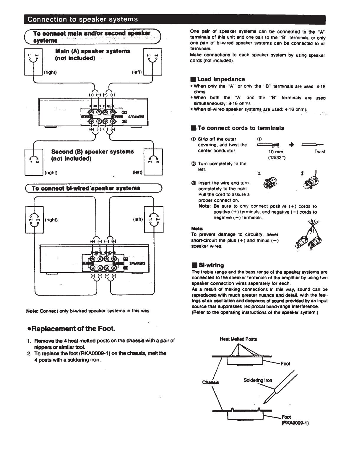
Load Impedance
A or B, BIWIRING 4 Ω1 6Ω
Aand B 8Ω16Ω
PRE AMP. SECTION
Input sensitivity a
Phono maximum Input voltage (1 kHz, RMS)
and impedance
PHONO MM 25 mV/47 kΩ
PHONO MC 170 µV/220 Ω
TUNER, CD, AUX, TAPE 1, TAPE 2/DAT 150 mV/22 kΩ
POWER AMP DIRECT 1 V/18 kΩ
MM 160 mV.
MC 12 mV.
2 x
50 W (8 Ω)
2x65 W (8 Ω)
R O M
2X9 0 W (4 Ω)
2 x
60 W (8
2
× 80 W (4
IMF'
IMF'
oM)
SUVX500
Areas
Country
Code
(E)
Continental Europe
Great Britain
(EB)
(EG)
F.R. Germany and Italy
Asia. Latin America.
(GC)
Middle Near E as t an d
Africa
(GN)
Oceania
S/N (rated power, 4 Ω)
PHONO MM 78 dB (85 dB. IMF' 66)
PHONO MC 66 dB (S = 250 µV. 67 dB, IHF` 66)
POWER AMP DIRECT
S/N at ~ 26 dB power (4 Ω)
PHONO MM 76 dB
PHONO MC 66 dB
Ω)
66
66
TUNER, CD, AUX, TAPE 1, TAPE 2/DAT 84 dB
SIN at 50 mW power (4 Ω)
PHONO MM 75 dB
PHONO MC 66 dB
TUNER, CD, AUX, TAPE 1, TA PE 2/DAT 78 dB
Frequency response
PHONO MM RIAA standard curve
TUNER, CD, AUX. TAPE 1, TAPE 2/DAT
POWER AMP DIRECT 2 Hz~120 kHz (+0, 3 dB)
Tone controls
BASS 50HZ, +10 dB, 10dB
TREBLE 20kHz +10 dB, 10 dB
Loudness control (volume at 30 dB ) 50 Hz. +9 dB
Output vo ltage
TAPE 1, TAPE 2/DAT REC OUT 150 mV
+0 dB, 0.2 dB (20 Hz~20 kHz)
+0 dB. 0.2 dB (20 Hz~20 kHz)
Amplifier
Color
(K) Black Typ e
Area
3Hz100kHz(+0, 3dB)
Color
97 dB (99 dB. IHF'66)
106
dB
(115
dB, IHF
±0.8 dB (30 Hz~15 kHz)
(K)
'661
Technics
Page 2

micro
SU-VX500
e
8
9
0
1
7
5
8
• GENERAL
Power consumption
Power supply
• for Great Britain and Oceania
F.R. Germany, Italy and Continental Europe:
for Others: AC 50760 Hz. 110 V/127 V/220 V/240 V
530 W
AC 50/60 Hz. 230/240 V
Dimension.
(W x H x D)
430x 125x316
Weight 8,1 kg (17.82 Ib.)
Notes:
1. Specifications are subject to change without notice.
Weight and dimensions are approximate.
2. Total harmonic distortion is measured by the digital spectrum
analyzer.
(16-15/16" x4-15/16"x 12-7/16")
mm
• CONTENTS
BEFORE REPAIR AND ADJUSTMENT 2 PRINTED CIRCUIT BOARDS 15-1
PROTECTION CIRCUITRY 2 WIRING CONNECTION DIAGRAM 1
ACCESSORY 2 BLOCK DIAGRAM 2
LOCATION OF CONTROLS 3 MEASUREMENTS AND ADJUSTMENTS 2
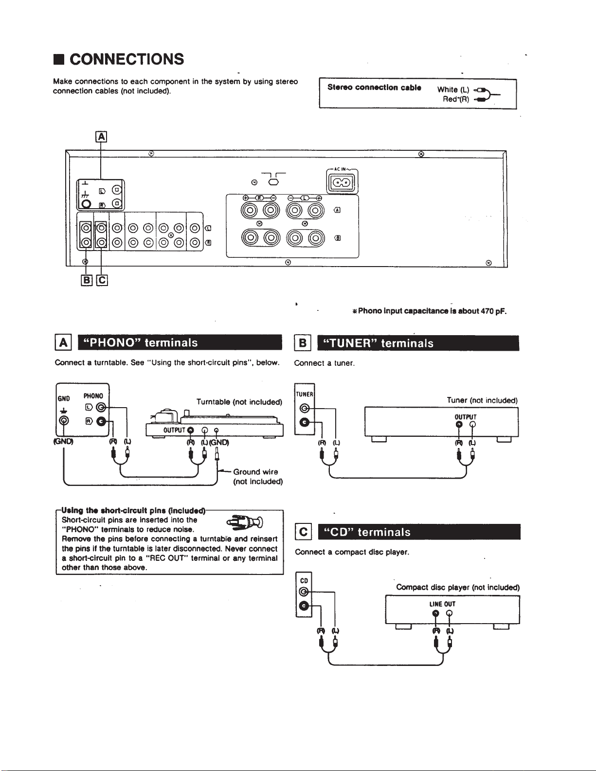
CONNECTIONS 4-6 REPLACEMENT PARTS LIST 22-24,2
DISASSEMBLY INSTRUCTIONS 7-10 CABINET PARTS LOCATION 25 2
SCHEMATIC DIAGRAM 11-14 PACKAGING ' 2
Page Pag
I BEFORE REPAIR AND ADJUSTMENT
(1) Tum off the power supply. Using a. 10oM, 10 W resistor, shortcircuit both ends of power supply capacitors C001, C002. C705
and C706 in order to discharge the voltage.
(2) Before turning on th e power switch of the unit,
A. Connect the voltage controller to the primary side.
B.
Connect
the AC
ampere
meter
to the
primary side
or
conned
the DC
voltage
meter
to the
"±B"
circuit
of the
side.
C. Turn the VR of ICQ (VR451, VR452. VR501 and VH502) to minimum (counterclockwise).
D.
Alter
setting
the
output
to
zero
of the
And increa se the output of voltage controller gradually.
Then, check carefully whether the current value of primary side become more than following value or whether the DC
voltage of secondary side is increasing slowly.
E. II the value of current is increasing unusually or the DC voltage is not increasing, lower the output level of voltage
controller Immediately.
•The current value of the primary side at no signal. (Confirm the power supply voltage ot each area and provided voltage of
the unit.)
Power supply voltage
Consumed current
voltage controller,
50 Hz
turn
AC 1 1 0 V
210-500
250-540 mA
AC
on the
120V
power switch
mA
AC 220V
90-370 mA
of the
unit.
80-360 mA
secondary
AC
230
V
AC
240
V
70-350 mA
I PROTECTION CIRCUITRY
The protection circuitry of the amplifier may have operated if either of
the following conditions is noticed:
•No sound Is heard when the power is turned on.
•Sound stops during a performance.
The function of thi s circ uitr y is to prevent circuitry damage if, for
example, the positive and negative speaker connection wires are
"shorted", or if speaker systems with an impedance less than the
indicated rated Impedance of the amplifier are used.
I ACCESSORY
It this occurs, follow the procedure outlined below:
1. Turn off the power.
2. Determine the cause of the problem and correct it.
3. Turn on the power once again.
Note:
When the protection circuitry functions, the unit w i ll not operate
unless
the
power
is
first
turned
off and
•AC power supply cords
<SFDAC05E03> For (E), (EG) areas.
<SJA193> For ( EB) a re a only.
<RJA0004> For (GC) area only.
<SJA173> For (GN) area only.
then
on
again.
-2-
Page 3

Page 4
Page 5

Page 6
Page 7

Page 8
Page 9

Page 10

Page 11

Page 12

Page 13

PRINTED CIRCUIT BOARD DIAGRAM
Page 14

SU-VX500 SU-VX500
5
6
7
PHONO PC.B.
8
9
PHONO SELECTOR
OPERATION PC.B.
Page 15

8
9
10
11
PHONO SELECTOR
INPUT SELECTOR P.C.B.
OPERATION PC.B.
Page 16

SU-VX500
SU-VX500
13
14
15
POWER SWITCH PC.B. For[E.EB, EG.GN) areas.
16
17
V-AMP PC.B
AC IN / VOLTAGE ADJ. PC. B. For[E, EB, EG.GN]areas
VOLTAGE ADJ
Page 17

SU-VX500
17
V-AMP PC.B
Power Source For (GC] area.
18
19
20
21
UPC4570C
AN7062N
2SA1309AQSTA
2SC3311AQSTA
2SA1535AQRS
2SC3944AQRS
18 Pin
8 Pin
22
SVI3205A
A
Anode
MA4033MTA
MA4036MTA
Cα
Δ
Anode
P300DLF
Anodβ
Ca
Cathode
Cathode
Ca
Cathode
Cathode
Cαthode
Page 18

Page 19

Page 20

Page 21

REPLACEMENT PARTS LIST
Notes : * Important safety notice:
Ref.Na
IC101
IC301
IC401
IC501
Q101104
101,
402
Q451.
452
Q453, 454
0455. 456
Q457. 458
0459, 460
0461,
462
0463, 464
Q465, 466
0501503
Q751
Q752
Q753, 754
Q755
Components identified by A mark have special characteristics important for safety.When replacing any of these
components use only manufacturer's specified parts.
* The
parenthesited
Parts without these indications can be used for all areas.
Part No.
UPC4570C
UPC4570C
AN7062N
SVI3205A
2SK170BLTPE2
2SA1123RSπA
2SC2631RSπA
2SC3311AQ
2SA1309AR
2SC2631RSπA
2SA1123RSπA
2SC3944AQRS
2SA1535AQRS
2SC1685RST
2SA992EFPTA
2SD2037DEFTA
2SB1357DEFTA
2SK301PQTA
2SA1309AR
Part
Name & Description
NTEGRATED CIRCUIT (S)
.C.PHONO/EQ.AMP.
. C, TONE AMP.
. C, VOLTAGE AMP.
. C, POWER AMP.
TRANSISTOR(S)
TRANSISTOR
TRANSISTOR
TRANSISTOR
TRANSISTOR
TRANSISTOR
TRANSISTOR
TRANSISTOR
TRANSISTOR
TRANSISTOR
TRANSISTOR
TRANSISTOR
TRANSISTOR
TRANSISTOR
TRANSISTOR
TRANSISTOR
indications
in the
Re•arks columns
Remarks
specify
VR202
VR301, 302
VR451. 452
TH201, 202
LI
L101.
L501504
the
Ref.Na
102
L551
Tl
Tl
Fl
Fl
F2
areas.
(Refer
Part
No.
EVJ02QFA2G15
EVJYA1FA2C15
EVNDXAAOOB52
RTD2ZHL104T
SLQZ650MH49
SLM1Z33
SLQY18G10
ELEPK2R2MA
RTP1N5E011
RTP1N5E012
XBA2C25TBO
XBA2C50TBO
XBA2C25TBO
Part
V. R, BALANCE
V. R. BASS/TREBLE CONT.
V. R. ICQ ADJ. (VAMP. )
THERMISTOR(S)
THERMISTOR
COIL(S)
COIL
COIL
COIL
COIL
TRANSFORMER(S)
POWER TRANSFORMER
PtWER TRANSFORMER
FUSE(S)
FUSE. 250V T2. 5A
FUSE. 250V T5A
FUSE, 250V T2. 5A
to the
cover page
Name & Description
for
area.)
Reaarks
∆(E.EB.EG,GN)
∆(E.EB,EG,GN)
∆(GC)
∆(E.EB,EG,GN)
∆(GC)
∆(GC)
D101.
102
D401.
402
D403, 404
D405, 406
D451
M53456
D501503
D503
D504
D601
D602
0603,604
D605
D702705
D751
VR201
MA165
MA167
MA4036MTA
MA165
MA29WA
MA165
MA165
MA4160M
MA4160M
1SR35200TB
LN014304P
LN018304P
MA4033TA
P300DLF
MA4180M
RRV16J02A
DIODE (S)
DIODE
DIODE
DIODE
DIODE
DIODE
DIODE
DIODE
DIODE
DIODE
DIODE
L.E.D.
LŁD.
DIODE
DIODE
DIODE
VARIABLE RESISTOR(S)
V.R. VOLUME CONTROL
SWITCH(ES)
SI
S2
S2
S101
S102
S103
S201
S202
S203
∆
S501
ESB8249V
ESD26200A
ESE37263
RSR6B002J
RSS6D001
RSS2D006A
ESB68107
ESB68132
RSP2DX8A
RSR4B004A
S». POWER
SW, VOLTAGE SELECTOR
SW, VOLTAGE SaECTOR
S», INPUT SELECTOR
S», REC SELECTOR
St. PHONO SELECTOR
SW.MODE
SW. LOUDNESS/TONE
SW. POWER AMP DIRECT
SW, SPFJiKER SELECTOR
CONNECTOR(S)
∆
∆(F,EB,EG.GN)
∆(GC)
A
CN101
CN102
CN103. 104
CN105107
CN201
RJU003K010U
RJU003K008M1
RJT060B05
RJU057W007
RJU003K010M1
SOCKET(IOP)
SOCKET(8P)
CONNECTOR(5P)
SOCKETS)
SOCKET (10P)
Page 22

Ref.No.
Part
No.
Part
Name
& Description
Remarks Ref.No.
Part
No.
Part
Name & Description
Remarks
CN202
CN401. 402
CN403
CN404
CN501
CN601
CN701
CN702A
CN702B
CP101
CP102
CP103, 104
CP105107
CP201
CP202
CP401, 402
CP403
CP404
CP501
CP601
Notes :
SJS50382JQH
RJT060B05
RJT060B07
RJU003K010M1
RJU057TO04
RJU003K008M1
RJP1A3303
RJS1A1703
RJS1A1704
RJT003KD10M1
RJT003KD08M1
RJU060G05T
RJT057W0071
RJT003KD10M1
SJT30345JQ
RJU060G05T
RJU060G07T
RJT003K010M1
RJTO5710041
RJT003KD08M1
* Capacity valuse are in
* Resistance values are
SOCKET (3P)
CONNECTOR (5P)
CONNECTOR (7P)
SOCKET (10P)
SOCKET (4P)
SOCKET (8P)
CONNECTOR (3P)
SOCKET (3P)
SOCKET ( 4P)
CONNECTOR (10P)
CONNECTOR (8P)
SOCKET (5P)
CONNECTOR (7P)
CONNECTOR (10P)
CONNECTOR (3P)
SOCKET (5P)
SOCKET(7P)
CONNECTOR (10P)
CONNECTOR (4P)
CONNECTOR (8P)
microfarads (uF) unless
in ohms, unless specified
FC1.2
FC3.4
RL501, 502
RL503
JK1
JK1
JK24
JK101
JK102
JK103
JK104
JK105
JK501
JK502
specified
otherwise.
FUSE HOLDER (S)
EYF52BC
SJT388
SSY134
RSY00090
SJS92311B
SJS9234B
SJS9233B
SJF30579N
SJF3069N
SJF3069N
SJF3069N
SJF3069N
RJH48011
QJA0455ZCA
otherwise, P=Picofarads (pF) F=Farads(F)
IK=l.000(OHM) , 1M=
FUSE HOLDER
FUSE HOLDER
RELAY (S)
RELAY
RELAY
JACK(S)
AC INLET
AC INLET
AC OUTLET
PHONO JACK
TUNER/CD JACK
AUX/TAPE1 REC. OUT JACK
TAPE1/PBAAPE2 REC. OUT JACK
TAPE2/PB/POWER AMP. JACK
SPEAKER TERMINAL
HEADPHONES JA CK
1.000k
(OHM)
(GC)
∆(E,EB,EG.GC)
∆(GN)
∆(GC)
Ref.No
RlOl104
R105,
106
R107,
108
R109,
110
Rlll116
R117.
118
R119.120
R121.
122
R123.124
R125,
126
R127.
128
R129,
130
R13L.
132
R201210
R211. 212
R213.
214
R215,
216
R217
R219.220
R221224
R225.226
R23L232
R233.234
R301.302
R303.304
No.
Part
ERDS2TJ102
ERDS2TJ274
ERDS2TJ221
ERDS2TJ220T
ERDAS3G332T
ERDS2TJ151
ERDS2TJ100
ERDS2TJ101
ERDS2TJ151
ERDS2TJ682T
ERDS2TJ823T
ERDS2TJ334
ERDS2TJ561
ERDAS3G102T
ERMS3G223T
ERDS2TJ183T
ERDS2TJ332
ERDS2TJ824
ERDAS3G272T
ERDS2TJ471
ERDAS3G102T
ERDAS3G472T
ERDAS3G124T
ERDAS3G561
ERDS2TJ823T
Values & Remarks
RESISTORS
1/4W
IK
1/4W 270K
1/4W
220
1/4W
22
1/4W
3. 3K
1/4W
150
1/4W
10
1/4W
100
1/4W
150
1/4W
6. 8K
1/4W
82K
1/4W 330K
1/4W
560
1/4W
1K
1/4W
22K
1/4W
18K
1/4W
3. 3K
1/4W 820K
1/4W
2. 7K
1/4W
470
1/4W
1K
1/4W 4.7K
1/4* 120K
1/4W
560
1/4W
82K
Ref.No.
R305. 306
R307, 308
R309. 310
R311,
312
R313,
314
R315.
316
R317. 318
R319,
320
R401,
402
R403.404
R405, 406
R407, 408
R409.410
R411.412
R437
R451.452
R455.456
R457
R459.460
R461464
R465468
R469.470
R471474
R501.502
R503.504
R5OS.506
R507. 508
R509512
Part Na
ERDS2TJ224T
ERDS2TJ392T
ERDS2TJ223
ERDS2TJ102
ERDS2TJ562
ERDAS3G392T
ERDAS3G223T
ERDS2TJ183T
ERDS2TJ122
ERDS2TJ823T
ERDAS3G272T
ERDAS3G823T
ERDS2TJ561
ERDFS2VJ470T
ERDS2TJ473
ERDFS2VJ182T
ERDFS2VJ391T
ERDS2TJ823T
ERDFS2VJ101T
ERDS2TJ223
ERDFS2VJ101T
ERDFS2VJ821T
ERDFS2VJ2R2T
ERDS2TJ362T
ERDFS2VJ121T
ERDS2TJ392T
ERDFS2VJ121T
ERF2EXKR10V
1/4W 220K
1/4W
1/4*
1/4W
1/4W
1/4W
1/4W
1/4W
1/4W
1/4W
1/4W
1/4W
1/4W
1/4W
1/4W
1/4W 1,8K
1/4W
1/4W
1/4*
1/4W
1/4W
l/4W
1/4W 3.6K
Values & Remarks
3. 9K
22K
1K
5. 6K
3.
9K
22K
18K
1. 2K
82K
2. 7K
82K
560
47
47K
390
82K
100
22K
1/4W
100
820
2,2
1/4W
120
1/4W 3,9K
1/4W
120
2W
0.1
Ref.No.
R513516
R517.
518
R519,
520
R521,
522∆
R527
R528
R529
R530∆
R531,
532
R533, 534
R555558
R559, 560
R561.
562
R563, 564
R565570
R601
∆
R604
R607
R707.708
R709, 710
R751,
752
R753. 754
R755
C001, 002
C1
∆
Part No.
ERDFS2VJ100T
ERDFS2VJ1R0T
ERDFS2VJ100T
ERDS1FVJ100T
ERDS2TJ223
ERDS2TJ824
ERDS2TJ124T
ERDS1FVJ682T
ERDS1FVJ100T
ERDS2TJ182
ERG1SJ561E
ERG1SJ102E
ERG1SJ151E
ERG1SJ181E
ERDS2TJ223
ERDS1FJ120
ERDS2TJ471
ERDS2TJ391
ERDFS2VJ6R8T
ERDFS2VJ470T
ERDFS2VJ221T
ERDS2TJ183T
ERDS2TJ102
ECED1HT682P
ECKWNS103ZVS
1/4W
1/4W
1/4W
1/2W
1/4W
1/4W 820K
1/4W 120K
1/2W 6.8K
1/2W
1/4W 1.8K
1/4W
1/2W
1/4W
1/4W
1/4W
1/4W
1/4W
1/4W
1/4W
CAPACITORS
500V 0.01U
Values & Remarks
10
1
10
10
22K
10
1W
560
1W 1K
1W
180
22K
12
470
390
6.8
47
220
18K
1K
50V 6800U
Page 23

Ref.No.
Part No.
Values & Remarks
Ref.
No.
Part Nα
Values & Reaarks
Cl0l, 102
C103,
104
C105,
106
C107,
108
C109.
110
C111,
112
Cl
13, 114
C115,
116
C117.
118
C119,
120
C121.
122
C123,
124
C125.
126
C201210
C213,
214
C219,
220
C221224
C225, 226
C301,
302
C303. 304
C305, 306
C307, 308
C309, 310
C311,
312
C313.
314
C315,
316
C317,
318
C319,
320
C321,
322
C401.
402
C403, 404
C405, 406
C407, 408
C409, 410
C411.
412
C413,
414
C415,
416
C426
C427
C428
C451,
452
C453456
C457460
C501504
C505, 506
C507
C508
C509
C511,
512
C513518
C519522
C523.524
ECBT1H120J5
ECBT1H102KB5
ECBT1H820KB5
ECA0JM222B
ECKW1H222KB5
ECQB1H122KF3
ECQB1H103KF3
ECQV1H393JZ3
UES1H010M1TA
ECQB1H472KF3
ECKR1H103ZF5
ECBT1H270J5
ECBT1H181KB5
ECCR1H101K5
ECQV1H563JZ3
ECCR1H271K5
ECBT1H181KB5
ECCR1H101K5
ECA1HPXS3R3B
ECCR1H101K5
ECBT1H820KB5
ECA1HPXS4R7B
ECBT1H390J5
ECA1CPXS100B
ECQV1H823JZ
ECQB1H153KF3
ECQB1H183KF3
ECQB1H182KF3
ECBT1E223ZF
ECA1HPXS3R3B
ECCR1H271K5
ECA1CPXS220B
ECBT1H820KB5
ECBT1H100J5
ECBA1H681KB5
ECCV2H070D
ECQB1H102KF3
ECBT1H102KB5
ECBT1E223ZF
ECKR1H103ZE5
ECKR1H33.3ZF5
ECCV2H680K
ECEA1HKA3R3B
ECAOJPXS101B
ECQV1H473JZ3
ECEAOJK/U01B
ECA1HM70B
ECEA1HN100SB
ECBT1H180J5
ECQV1H473JZ3
ECQB1H153KF3
ECBT1H102KB5
50V 12P
50V 1000P
50V 82P
6.3V 2200U
50V 2200P
50V 1200P
50V
50V 0.039U
50V 1U
50V 4700P
50V
50V 27P
50V
50V
50V 0, 056U
50V 270P
50V
50V
50V
50V 100 P
50V 82P
50V 4. 7U
50V 39P
16V 10U
50V 0. 082U
50V
50V
50V 1800P
25V 0. 022U
50V
50V 270P
16V 22U
50V 82P
50V 10P
50V 680P
500V 7P
50V 1000P
50V 1000P
25V 0. 022U
50V
50V 0. 033U
500V 68P
50V
6. 3V
50V 0.047U
6. 3V
50V 47U
50V 10U
50V 18P
50V0.047U
50V0.015U
50V 1000P
0.01U
0.01U
180P
100P
180P
100P
3. 3U
0.
015U
0.
018U
3. 3U
0.01U
3. 3U
100U
100U
C525. 526
C531.
532
C551.552
C601
C705. 706
C707709
C711
C712
C751756
ECQB1H272JF3
ECBT1C332KR5
ECEA1JU010B
ECA1CM221B
ECA1JPXS221B
ECA1JAP220B
ECQE2104KF3
ECKR1H103ZF5
ECA1HPXS4R7B
50V 2700P
16V 3300P
63V
16V 220U
63V 220U
63V 22U
100V
50V 0.0
50V
1U
0. 1U
1U
4.7U
Page 24

Page 25

Ref . No.
Part No.
Part Name & Description
. Remarks
Ref.No.
Part No.
Part
Name & Description
Remarks
10
11
12
12
12
12
13
14
15
16
161
17
18
19
20
21
22
23
24
25
26
27
28
29
30
31
32
33
34
35
36
36
37
38
39
40
41
43
44
CABINET PARTS L I ST
RGW0124K
RGW0126K
RGW0127K1
RKM0036AK
RKM0179K
SJPA111
SNE2 1291
XTBS3+8JFZ1
XTW3+8T SCREW
SHR415
SUS227
RFKGUVX500EK
RGR0129AD1
RGR0129AF1
RGR0129AE1
RGR0129BA1
RGU0030 BUTTON, POWER
RGU0509K
RHN90001
RFKJUVX500EK
RKA00091
RMN0143
KNOB, TONE
KNOB, SELECTOR
KNOB, VOLUME
CABINET
CABINET
SHORT P I N
SCREW
SCREW
CLAMPER
SPRING (AK451. 452)
FRONT PANEL ASS` Y
REAR PANEL
REAR PANEL
REAR RANEL
REAR PANEL
BUTTON, MODE
NUT
BOTTOM BOARD ASS' Y
FOOT
HOLDER
RMNOH9 HOLDER
RMQ0259 ANGLE
RSQ0022
RSQ0023
RGKD394A
RGKD412K
RGKD413K
RGK0414K
RGL0134C
RGL0136C
RGU0611K
RMR0460K HOLDER
RMR0461K
RMR0502
RSC0245
XTBS26+8J
SHE1873
SHR9814
SJS9231A
SJS9234A
SNE2123
XTB3+16JFZ
XTB3+20JFZ
XTB3+8JFZ
XTfS3+8T
RGKD415K
SJS9233A
REMOTE SWITCH(REC. )
REMOTE SW ITC H (PHONO)
RING
SIDE ORNAMENT(L)
SIDE ORNAMENT (R)
VOLUME ORNAMENT
ORNAMENT
ORNAMENT
BUTTON, POWER AMP. DIRECT
HOLDER
HOLDER
SHIELD PLATE
SCREW
SPACER
CLAMPER
AC I NLE T COVER
AC INLET COVER
GND SCREW
SCREW
SCREW
SCREW
SCREW
UPPER PLATE
AC OUTLET COVER
(E, EG, GC, GN)
(EB)
(E)
(EG)
(EB,
GN)
(GC)
(E, EB, EG, GC)
(GN)
(EB)
(GC)
45
46
P1
P2 RPN0539
P3
P4
P5
Al RQF1226 INSTRUCTIONS MANUAL ASS' Y (E)
Al
Al RQF1228 INSTRUCTIONS MANUAL ASS' Y (EG )
Al
Al RQF1229 INSTRUCTIONS MANUAL ASS' Y (GC)
Al 1 RFKSUVX500EK INSTRUCTIONS MANUAL (E)
Al1 RQTU61B INSTRUCTIONS MANUAL (EB)
Al1
Al1
A12
Al3
A2
A2
A2
A2
A3
XYN3+C6FZ
RWJ3907130QQ
RPG0975
XZB24X34C04 PROTECTION COVER
SPB1061 [P RO TECTION COVER (MANUAL)
RPQ0164 ACCESSORY BOX
RQF1227
RQF1230 INSTRUCTIONS MANUAL ASS' Y (GN)
RQT1162D INSTRUCTIONS MANUAL (EG )
RQT1159G INSTRUCTIONS MANUAL (GC. GN)
RQA0013 WARRANTY CARD
RQCB0169
SFDAC05E03
SJA193
SJA173
RJA0004 AC POWER SUPPLY CORD ∆ (GC)
SJP9215
SCREW (GC)
CABLE ASS' Y(W702)
PACKIN G MATERIALS
PACKING CASE
PAD
ACCESSORIES
INSTRUCTIONS MANUAL ASS' Y (EB)
SERVICE CENTER LIST
AC POWER SUPPLY CORD ∆(E. EG)
AC POWER SUPPLY CORD ∆ (EB)
AC POWER SUPPLY CORD ∆ (GN)
AC
PLUG ADAPTOR
∆
(GC)
Page 26

 Loading...