

Page 1
SU-G700
Stereo Integrated Amplifier Owner’s Manual
Amplificateur intégré stéréo Manuel d’utilisation
Page 2

Page 3

Music is borderless and timeless, touching people’s
hearts across cultures and generations.
Each day the discovery of a truly emotive experience
from an unencountered sound awaits.
Let us take you on your journey to rediscover music.
Sans frontières, la musique est aussi intemporelle,
touchant le coeur des gens en traversant les cultures et
les générations.
Tous les jours, nous attendons la révélation d’une
expérience émotionnelle authentique à partir d’un son
venu de nulle part.
Permettez-nous de vous emmener en voyage pour
redécouvrir la musique.
(03)
03
Page 4

04
(04)
Page 5

Delivering the Ultimate Emotive Musical
Experience to All
At Technics we understand that the listening experience is not purely
about technology but the magical and emotional relationship between
people and music.
We want people to experience music as it was originally intended
and enable them to feel the emotional impact that enthuses and
delights them.
Through delivering this experience we want to support the
development and enjoyment of the world’s many musical cultures.
This is our philosophy.
With a combination of our love of music and the vast high-end audio
experience of the Technics team, we stand committed to building a
brand that provides the ultimate emotive musical experience by music
lovers, for music lovers.
Apportez à tous l’expérience musicale
empreinte d’émotions
Chez Technics, nous savons que l’expérience de l’écoute n’est pas
purement et simplement une question de technologie, mais de
relation magique entre les personnes et la musique.
Nous voulons que tout un chacun puisse ressentir la musique telle
qu’elle a été conçue à l’origine et lui permettre de ressentir le choc
émotionnel qu’il brûle de connaître.
En apportant ce vécu, nous cherchons à accompagner le
développement et le plaisir des nombreuses cultures musicales du
monde. Telle est notre philosophie.
Ici et maintenant, alliant l’amour de la musique et la grande
expérience musicale de l’équipe Technics, nous sommes pleinement
déterminés à construire une marque qui apporte le vécu musical
émotionnel aux fervents de la musique.
Director
Directeur
Michiko Ogawa
(05)
05
Page 6

Thank you for purchasing this product.
Please read these instructions carefully before using this product, and save this manual for future use.
• About descriptions in this Owner’s Manual
- Pages to be referred to are indicated as “ ○○”.
- The illustrations shown may differ from your unit.
If you have any questions, visit:
U.S.A.: http://shop.panasonic.com/support
Canada: www.panasonic.ca/english/support
Register online at http://shop.panasonic.com/support (U.S. customers only)
Features
High-Quality Audio Technologies
Employed including JENO Engine
and LAPC
The JENO Engine transmits and processes audio
signals in full digital and with minimal jitter from
the input stage to the power stage. The LAPC
conducts speaker load adaptive phase calibration
to achieve ideal gain and phase characteristics
for any type of speaker. Also, a unique, highprecision PWM conversion circuit is used for
PWM conversion, which is important for sound
quality.
Three-section Configuration
High Rigidity Aluminum Cabinet
The high-rigidity metal double chassis features
a steel-plate inner chassis and a steel-plate
outer chassis to reduce vibration and noise that
degrade the purity of sound.
In integrated amplifiers, there are a variety of
circuits such as circuits handling the microsignals of input, circuits handling large current,
etc. SU-G700 uses a three-section construction
with partitions installed between the circuit
blocks according to the signal level handled. This
eliminates interference between circuit blocks,
thus achieving clear sound quality.
(06)
06
Page 7
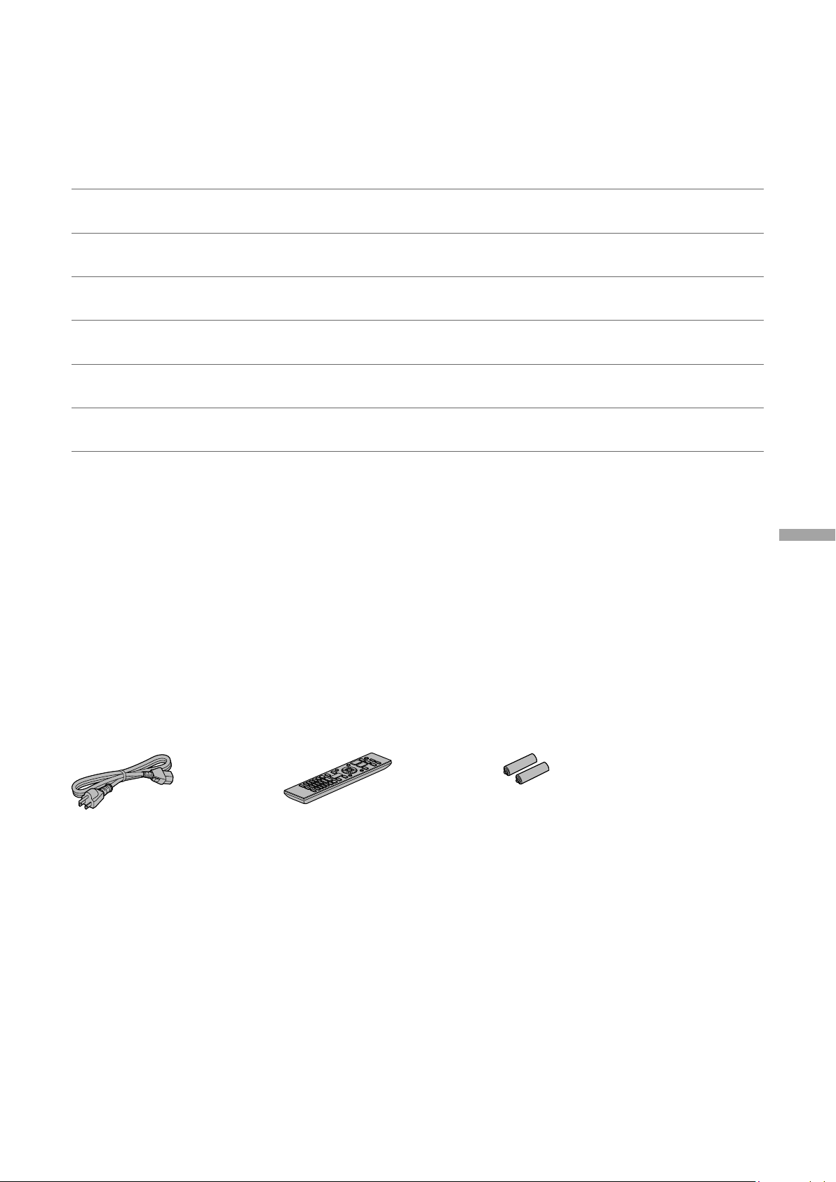
Table of contents
IMPORTANT SAFETY
08
INSTRUCTIONS
Control reference guide 10
Connections 14
Operations 16
Settings 24
Troubleshooting 30
Others 33
Please carefully read the “IMPORTANT SAFETY
INSTRUCTIONS” of this manual before use.
This unit, Remote control
Speaker connection, AC power supply cord
connection
Playing back connected devices
Other settings, Using output correction function
(LAPC)
Before requesting service, read the
troubleshooting.
Specifications, etc.
English
Accessories
AC power supply cord (1)
K2CG3YY00191
(ONLY FOR CANADA)
The enclosed Canadian French label sheet corresponds to the English display on the unit.
• Product numbers provided in this Owner’s Manual are correct as of February 2017.
• These may be subject to change.
• Do not use AC power supply cord with other equipment.
Remote control (1)
N2QAYA000143
Batteries for remote
control (2)
(07)
07
Page 8

IMPORTANT SAFETY INSTRUCTIONS
Read these operating instructions carefully before
using the unit. Follow the safety instructions on the
unit and the applicable safety instructions listed below.
Keep these operating instructions handy for future
reference.
1 Read these instructions.
2 Keep these instructions.
3 Heed all warnings.
4 Follow all instructions.
5 Do not use this apparatus near water.
6 Clean only with dry cloth.
7 Do not block any ventilation openings. Install in
accordance with the manufacturer’s instructions.
8 Do not install near any heat sources such as
radiators, heat registers, stoves, or other apparatus
(including amplifiers) that produce heat.
9 Do not defeat the safety purpose of the polarized
or grounding-type plug. A polarized plug has two
blades with one wider than the other. A groundingtype plug has two blades and a third grounding
prong. The wide blade or the third prong are
provided for your safety. If the provided plug does
not fit into your outlet, consult an electrician for
replacement of the obsolete outlet.
10 Protect the power cord from being walked on
or pinched particularly at plugs, convenience
receptacles, and the point where they exit from the
apparatus.
11 Only use attachments/accessories specified by the
manufacturer.
12 Use only with the cart, stand,
tripod, bracket, or table specified
by the manufacturer, or sold with
the apparatus. When a cart is used,
use caution when moving the cart/
apparatus combination to avoid injury
from tip-over.
13 Unplug this apparatus during lightning storms or
when unused for long periods of time.
14 Refer all servicing to qualified service personnel.
Servicing is required when the apparatus has been
damaged in any way, such as power-supply cord or
plug is damaged, liquid has been spilled or objects
have fallen into the apparatus, the apparatus has
been exposed to rain or moisture, does not operate
normally, or has been dropped.
Warning
Unit
• To reduce the risk of fire, electric shock or product
damage,
- Do not expose this unit to rain, moisture, dripping
or splashing.
- Do not place objects filled with liquids, such as
vases, on this unit.
- Use only the recommended accessories.
- Do not remove covers.
- Do not repair this unit by yourself. Refer servicing
to qualified service personnel.
- Do not let metal objects fall inside this unit.
- Do not place heavy items on this unit.
AC power supply cord
• The power plug is the disconnecting device.
Install this unit so that the power plug can be
unplugged from the socket outlet immediately.
• Ensure the earth pin on the power plug is securely
connected to prevent electrical shock.
- An apparatus with CLASS I construction shall
be connected to a power socket outlet with a
protective earthing connection.
Caution
Unit
• Do not place sources of naked flames, such as lighted
candles, on this unit.
• This unit may receive radio interference caused by
mobile telephones during use. If such interference
occurs, please increase separation between this unit
and the mobile telephone.
• Do not touch the top surface of this unit. This unit
becomes hot while it is on.
Placement
• Place this unit on an even surface.
• To reduce the risk of fire, electric shock or product
damage,
- Do not install or place this unit in a bookcase, built-
in cabinet or in another confined space. Ensure this
unit is well ventilated.
- Do not obstruct this unit’s ventilation openings
with newspapers, tablecloths, curtains, and similar
items.
- Do not expose this unit to direct sunlight, high
temperatures, high humidity, and excessive
vibration.
• Ensure that the placement location is sturdy enough
to accommodate the weight of this unit ( 34).
• Keep your speakers at least 10 mm (
the system for proper ventilation.
• Do not lift or carry this unit by holding the knobs.
Doing so may cause this unit to fall, resulting in
personal injury or malfunction of this unit.
Battery
• Danger of explosion if battery is incorrectly replaced.
Replace only with the type recommended by the
manufacturer.
• Mishandling of batteries can cause electrolyte
leakage and may cause a fire.
- Remove the battery if you do not intend to use the
remote control for a long period of time. Store in a
cool, dark place.
- Do not heat or expose to flame.
- Do not leave the battery(ies) in a car exposed to
direct sunlight for a long period of time with doors
and windows closed.
- Do not take apart or short circuit.
- Do not recharge alkaline or manganese batteries.
- Do not use batteries if the covering has been
peeled off.
- Do not mix old and new batteries or different types
at the same time.
• When disposing of the batteries, please contact your
local authorities or dealer and ask for the correct
method of disposal.
13
/32”) away from
08
(08)
Page 9
CAUTION
RISK OF ELECTRIC SHOCK
CAUTION: TO REDUCE THE RISK OF ELECTRIC
Conforms to UL STD 60065.
Certified to CAN/CSA STD C22.2 No.60065.
THE FOLLOWING APPLIES ONLY IN CANADA.
CAN ICES-3(B)/NMB-3(B)
Information on Disposal in other
Countries outside the European Union
DO NOT OPEN
SHOCK, DO NOT REMOVE SCREWS.
NO USER-SERVICEABLE PARTS INSIDE.
REFER SERVICING TO QUALIFIED
SERVICE PERSONNEL.
The lightning flash with arrowhead
symbol, within an equilateral triangle,
is intended to alert the user to the
presence of uninsulated “dangerous
voltage” within the product’s enclosure
that may be of sufficient magnitude
to constitute a risk of electric shock to
persons.
The exclamation point within an
equilateral triangle is intended to
alert the user to the presence of
important operating and maintenance
(servicing) instructions in the literature
accompanying the appliance.
This symbol is only valid in the European
Union.
If you wish to discard this product, please
contact your local authorities or dealer and
ask for the correct method of disposal.
THE FOLLOWING APPLIES ONLY IN THE U.S.A.
FCC Note:
This equipment has been tested and found to comply
with the limits for a Class B digital device, pursuant to
Part 15 of the FCC Rules.
These limits are designed to provide reasonable
protection against harmful interference in a
residential installation. This equipment generates,
uses, and can radiate radio frequency energy and,
if not installed and used in accordance with the
instructions, may cause harmful interference to radio
communications.
However, there is no guarantee that interference will
not occur in a particular installation. If this equipment
does cause harmful interference to radio or television
reception, which can be determined by turning the
equipment off and on, the user is encouraged to try
to correct the interference by one or more of the
following measures:
• Reorient or relocate the receiving antenna.
• Increase the separation between the equipment
and receiver.
• Connect the equipment into an outlet on a
circuit different from that to which the receiver is
connected.
• Consult the dealer or an experienced radio/TV
technician for help.
FCC Caution: To assure continued compliance,
follow the attached installation instructions and use
only shielded interface cables when connecting to
peripheral devices.
Any changes or modifications not expressly approved
by the party responsible for compliance could void
the user’s authority to operate this equipment.
This device complies with Part 15 of the FCC Rules.
Operation is subject to the following two conditions:
(1) This device may not cause harmful interference,
and (2) this device must accept any interference
received, including interference that may cause
undesired operation.
Declaration of Conformity
Trade Name: Technics
Model No.: SU-G700
Responsible Party:
Panasonic Corporation of North America
Two Riverfront Plaza, Newark, NJ 07102-5490
Support Contact:
http://shop.panasonic.com/support
English
SU-G700
IMPORTANT SAFETY INSTRUCTIONS
(09)
09
Page 10
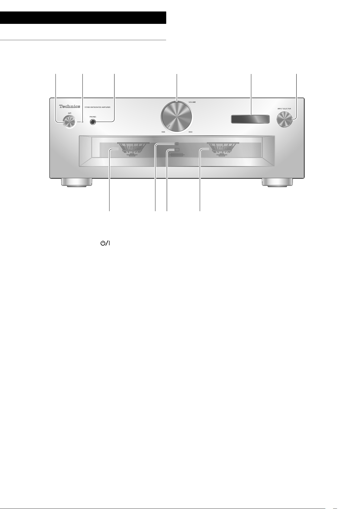
Control reference guide
This unit
01 Standby/on button ( )
• Press to switch the unit from on to standby
mode or vice versa. In standby mode, the
unit is still consuming a small amount of
power.
02 Power indicator
• Blue: The unit is on.
• Off: The unit is in standby mode.
03 Headphones jack
• When a plug is connected, the speakers and
PRE OUT terminals do not output sound.
( 22)
• Sound is not output from headphones jack
while “MAIN IN” is selected as input source
of this unit. ( 20)
• Excessive sound pressure from earphones
and headphones can cause hearing loss.
• Listening at full volume for long periods may
damage the user’s ears.
07 Peak power meter
• Display the output level. 100 % is the rated
output ( 34).
• Peak power meter does not work while the
light is turned off.
08 LAPC indicator ( 26)
09 Remote control signal sensor
• Reception distance: Within approx. 7 m
(23 ft) directly in front
• Reception angle: Approx. 30° left and right
04 Volume knob
• -- (min), 1 to 100 (max)
• To display the volume, set “VOLUME
Display” to “On”. ( 25)
05 Display
• Information such as input source, etc. is
displayed. ( 32)
06 Input selector knob
• Turn this knob clockwise or anticlockwise to
switch the input source.
(10)
10
Page 11
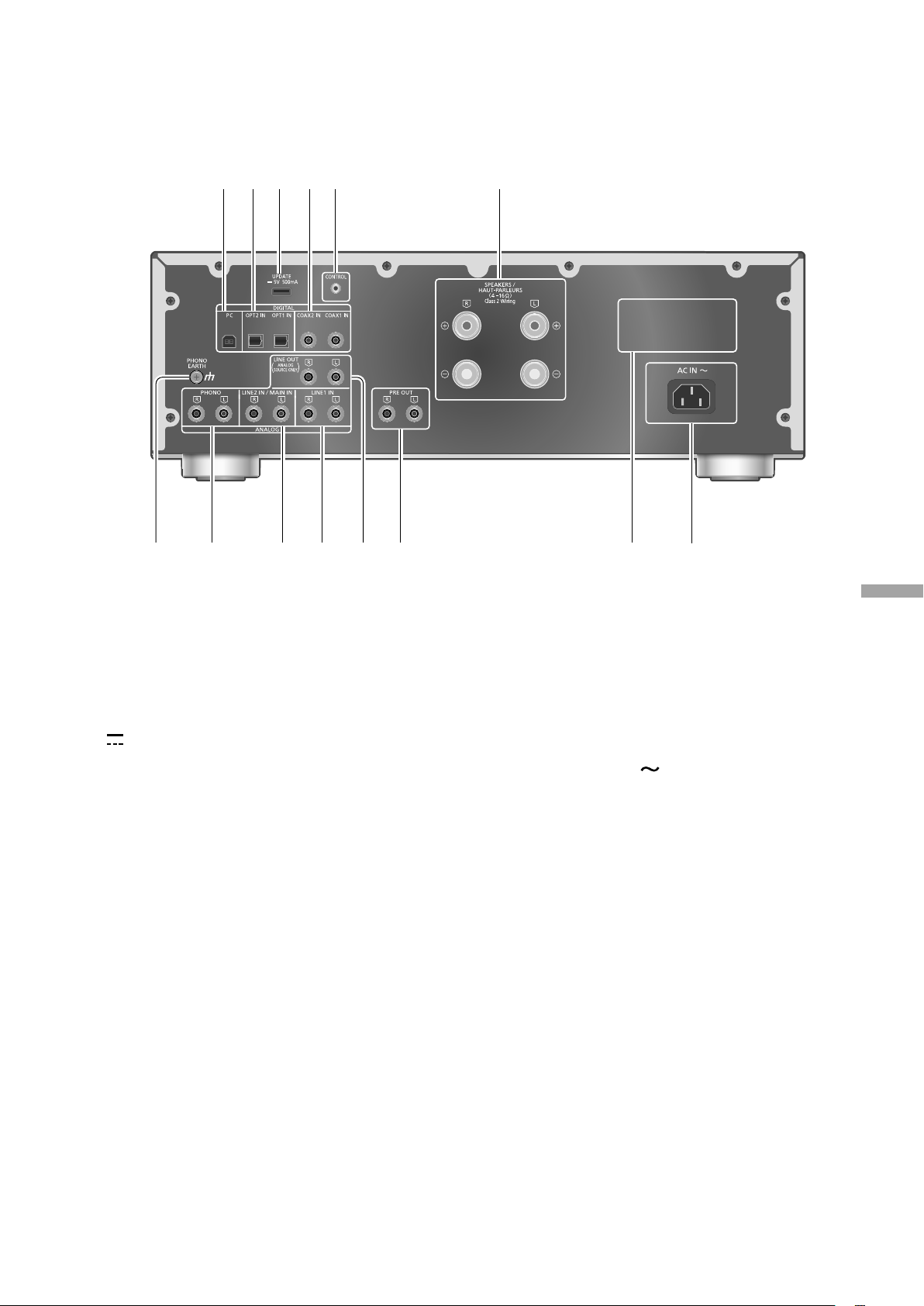
10 USB-B terminal
• For connecting to a PC, etc. ( 17)
11 Optical digital input terminal
(OPT1 IN/OPT2 IN) ( 16)
12 UPDATE terminal (USB-A)
DC 5 V 500 mA) ( 27)
(
13 Coaxial digital input terminals
(COAX1 IN/COAX2 IN) ( 16)
14 System terminal (CONTROL) ( 28)
15 Speaker output terminals ( 14)
16 PHONO EARTH terminal ( 18)
• For connecting the ground wire of a
turntable.
17 Analog audio input terminals (PHONO)
( 18)
• MM cartridges are supported.
20 Analog audio output terminals
(LINE OUT) ( 23)
21 Analog audio output terminals (PRE OUT)
( 22)
22 Product identification marking
• The model number is indicated.
23 AC IN terminal (
) ( 15)
English
18 Analog audio input terminals
(LINE2 IN/MAIN IN)
• These input terminals are combined with
LINE2 IN and MAIN IN. Switch the function
according to the connected equipment.
( 19, 20)
19 Analog audio input terminals (LINE1 IN)
( 19)
Control reference guide
(11)
11
Page 12
Control reference guide
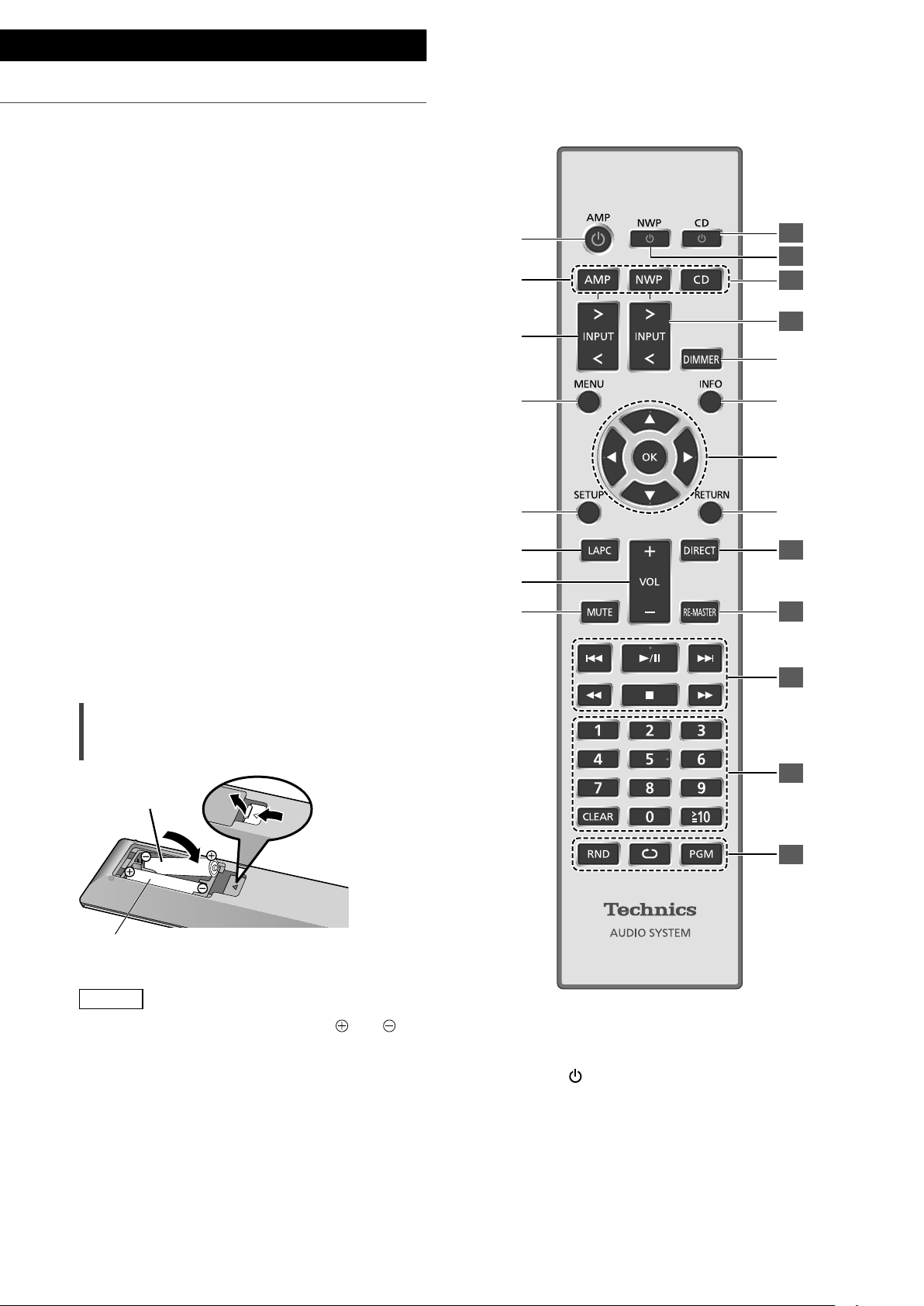
Remote control
Using the remote control
2
1
R03/LR03, AAA
(Alkaline or manganese batteries)
Note
• Insert the battery so the terminals (
match those in the remote control.
• Point it at the remote control signal sensor on
this unit. ( 10)
• Keep the batteries out of reach of children to
prevent swallowing.
(12)
12
and )
01 [AMP ]: Standby/on button
• Press to switch the unit from on to standby
mode or vice versa. In standby mode, the
unit is still consuming a small amount of
power.
02 [AMP]/[NWP]/[CD]:
Select the device to be operated
Page 13

03 [>INPUT<]: Switch the input source
( 16, 17, 18, 19, 20)
04 [MENU]: Enter menu ( 18, 19, 20, 21)
05 [SETUP]: Enter setup menu ( 24)
06 [LAPC]: Measure the output signal of the
amplifier when speakers are connected,
and correct its output ( 26)
07 [+VOL-]: Adjust the volume
• Volume range: -- (min), 1 to 100 (max)
08 [MUTE]: Mute the sound
• Press [MUTE] again to cancel. “MUTE” is
also cancelled when you adjust the volume
with this unit or when you turn the unit to
standby.
09 [DIMMER]: Adjust the brightness of the
peak power meter light, display, etc.
• When the display is turned off, it will
light up for a few seconds only when you
operate this unit. Before the display turns
off, “Display Off” will be displayed for a few
seconds.
• Press repeatedly to switch the brightness.
• Peak power meter does not work while the
light is turned off.
10 [INFO]: View content information
• Press this button to display sampling
frequency and other information. (The
information varies depending on the input
source.)
11 [
], [ ], [ ], [ ]/[OK]: Selection/OK
12 [RETURN]: Return to the previous display
: Press [AMP] first to operate this unit. (The
*
remote control may work for other Technics
devices and may not for this unit when
pressing [NWP] or [CD].)
*
*
*
*
■ Buttons that work for Technics devices
supporting system control function
The remote control of this unit also works for
Technics devices supporting system control
function (Network Audio Player, Compact Disc
Player, etc.). For information on the operations of
the devices, please also refer to their operating
instructions.
[ ] Standby/on switch for the Compact
01
Disc Player
[ ] Standby/on switch for the Network
02
Audio Player
Select the device to be operated
03
Select the input source of the Network
04
Audio Player
Turn on/off Direct mode
05
Turn on/off Re-master
06
Playback control buttons
07
Numeric buttons, etc.
08
Playback control buttons
09
Remote control mode
When other equipment responds to the supplied
remote control, change the remote control
mode.
• The factory default is “Mode 1”.
1 Press [AMP].
English
2 Press [SETUP].
3 Press [
], [ ] repeatedly to select
“Remote Control” and then press
[OK].
• The current remote control mode of this unit
is displayed for a few seconds.
4 When “Set Mode 1/2” is displayed,
change the remote control mode of
the remote control.
To set “Mode 1”:
Press and hold [OK] and [1] for at least 4
*
seconds.
To set “Mode 2”:
Press and hold [OK] and [2] for at least 4
seconds.
5 Point the remote control at this unit,
and press and hold [OK] for at least 4
seconds.
• When the remote control mode is changed,
the new mode will appear on the display for
a few seconds.
■ When “Remote 1” or “Remote 2” is
displayed
When “Remote 1” or “Remote 2” is displayed,
the remote control modes of this unit and
remote control are different. Perform step 3
above.
Control reference guide
(13)
13
Page 14
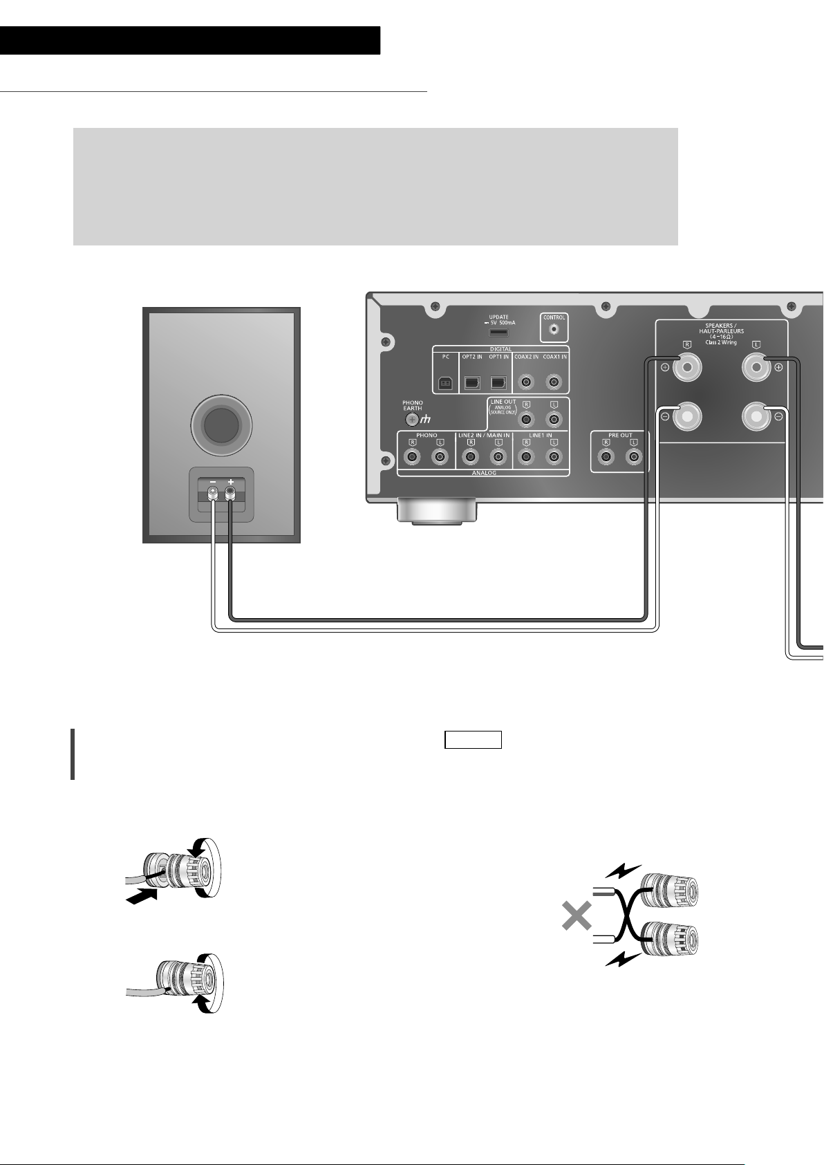
Connections
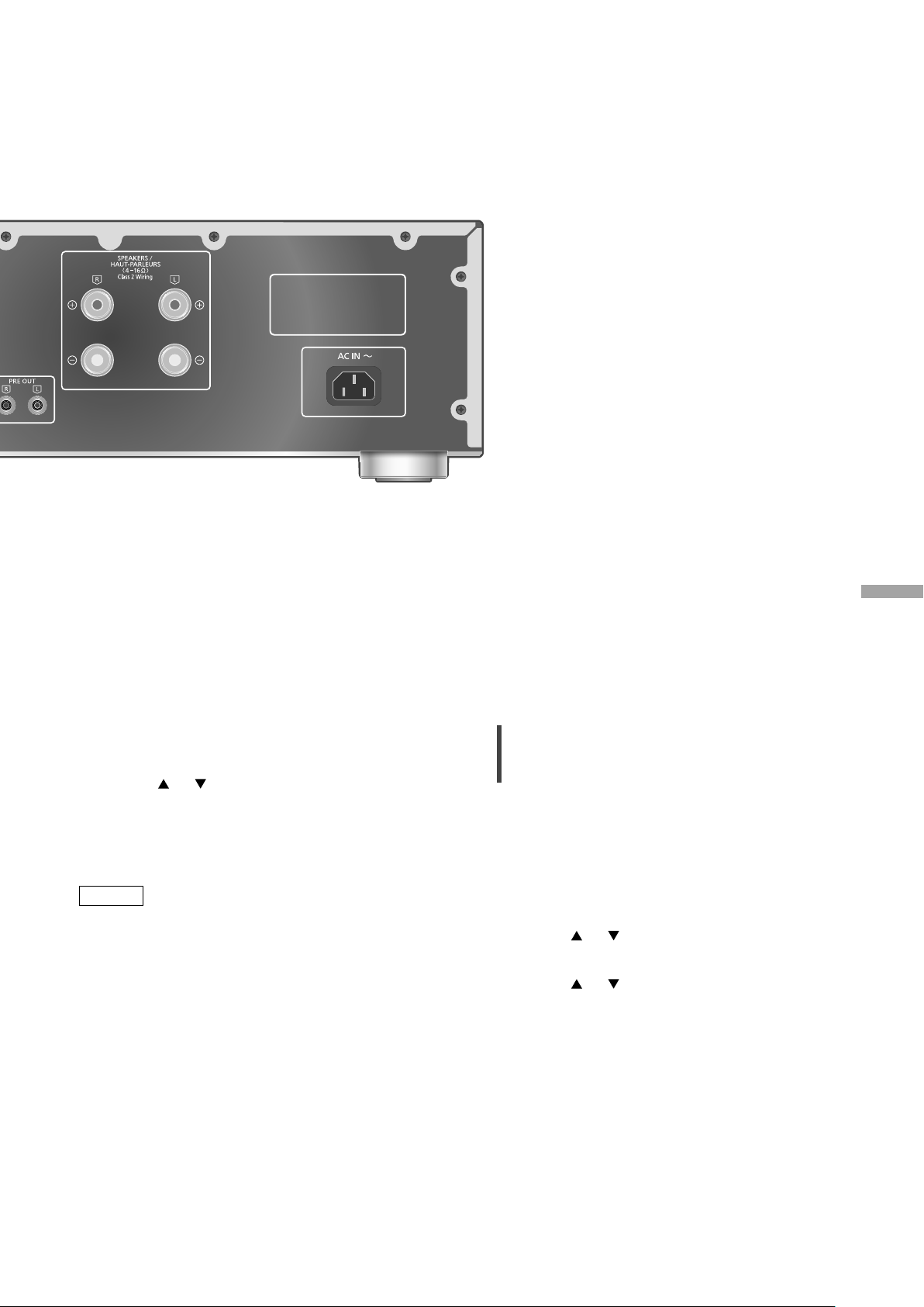
Speakers/AC power supply cord
• Use only the supplied AC power supply cord.
• Do not connect the AC power supply cord until all other connections are complete.
• Insert the plugs of the cables to be connected all the way in.
• Do not bend cables at sharp angles.
• To optimize the audio output, you can measure the amplifier output signal and correct its
output when it is connected to the speakers. ( 26)
Speaker cable (not supplied)
Speaker connection
1 Turn the knobs to loosen them, and
insert the core wires into the holes.
2 Tighten the knobs.
Note
• When the connections are completed, pull the
speaker cables lightly to check that they are
connected firmly.
• Be careful not to cross (short-circuit) or reverse
the polarity of the speaker wires as doing so
may damage the amplifier.
DO NOT
• Wire the polarity (+/-) of the terminals correctly.
Not doing so may adversely affect stereo
effects or cause malfunction.
• For details, refer to the operating instructions of
the speakers.
14
(14)
Page 15
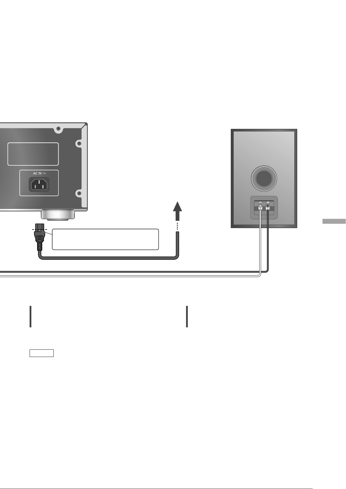
Insert the AC power supply cord up
to a point just before the round hole.
AC power supply cord (supplied)
Speaker cable (not supplied)
To a household
AC outlet
English
AC power supply cord connection
Connect only after all other connections are
completed.
Note
• This unit consumes a small amount of AC power
( 34) even when the unit is in standby mode.
Remove the plug from the main electrical outlet
if you will not be using the unit for an extended
period of time. Place the unit so the plug can be
easily removed.
Speaker output correction (LAPC)
You can make the optimum adjustment
according to your own speakers. ( 26)
Connections
(15)
15
Page 16
Operations
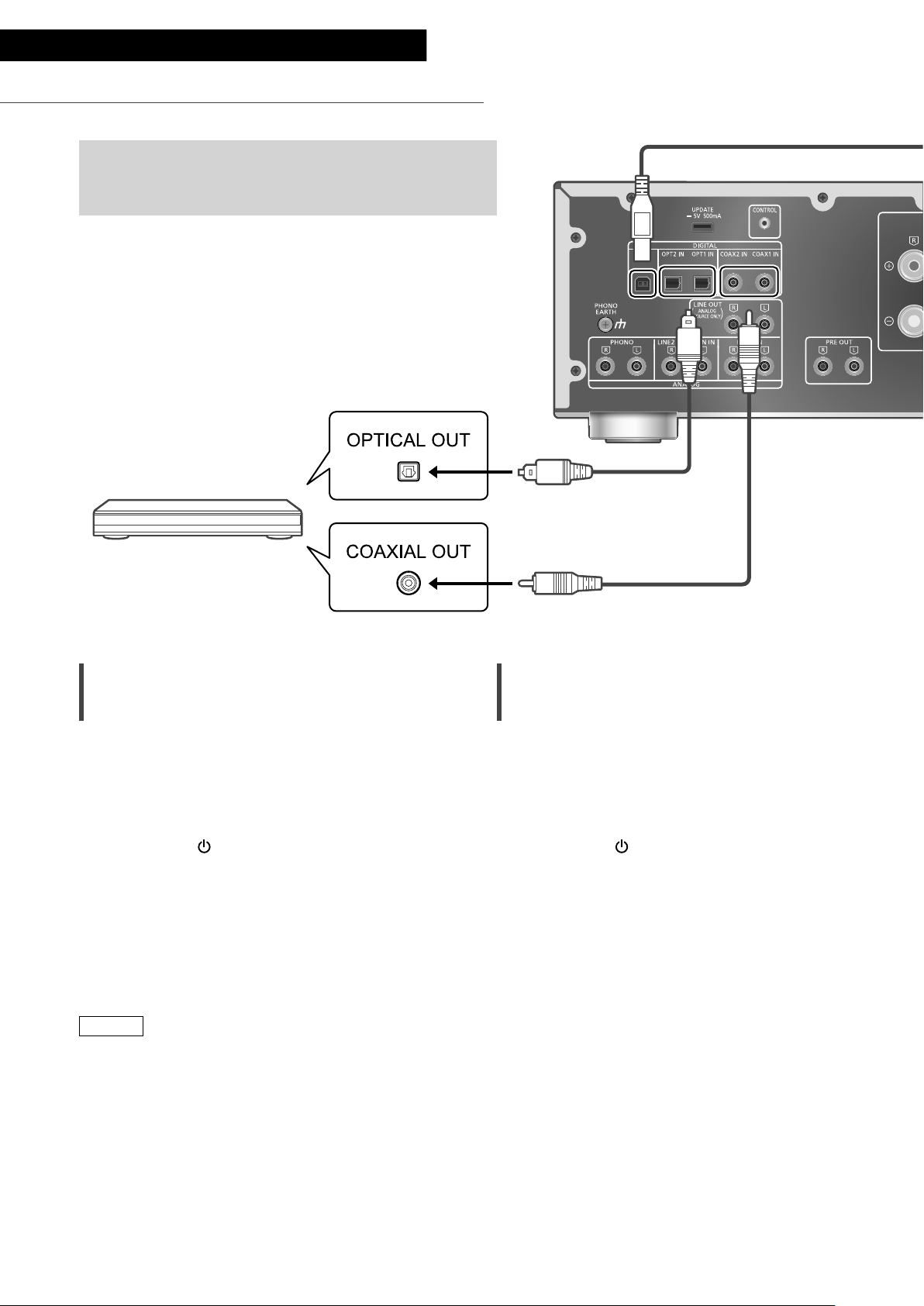
Using digital audio output device
You can connect the CD player, etc. with coaxial digital
cable (not supplied)/optical digital audio cable (not
supplied) to this unit and play back music.
Optical digital audio cable
(not supplied)
CD player, etc.
Using coaxial digital cable
1 Disconnect the AC power supply cord.
2 Connect this unit and a CD player, etc.
3 Connect the AC power supply cord to
this unit. ( 15)
4 Press [AMP
5 Press [>INPUT<] repeatedly to select
“COAX1” or “COAX2”.
• You can also select the input source by
turning the input selector knob on the unit.
6 Start playback on the connected
device.
] to turn this unit on.
Coaxial digital cable
(not supplied)
Using optical digital audio cable
1 Disconnect the AC power supply cord.
2 Connect this unit and a CD player, etc.
3 Connect the AC power supply cord to
this unit. ( 15)
4 Press [AMP
5 Press [>INPUT<] repeatedly to select
“OPT1” or “OPT2”.
• You can also select the input source by
turning the input selector knob on the unit.
6 Start playback on the connected
device.
] to turn this unit on.
Note
• The digital audio input terminals of this unit can
only detect the following linear PCM signals.
For details, refer to the operating instructions of
the connected device.
- Sampling frequency:
Coaxial digital input
32/44.1/48/88.2/96/176.4/192 kHz
Optical digital input
32/44.1/48/88.2/96 kHz
- Number of quantization bits:
16/24 bit
(16)
16
Page 17
USB 2.0 cable
(not supplied)
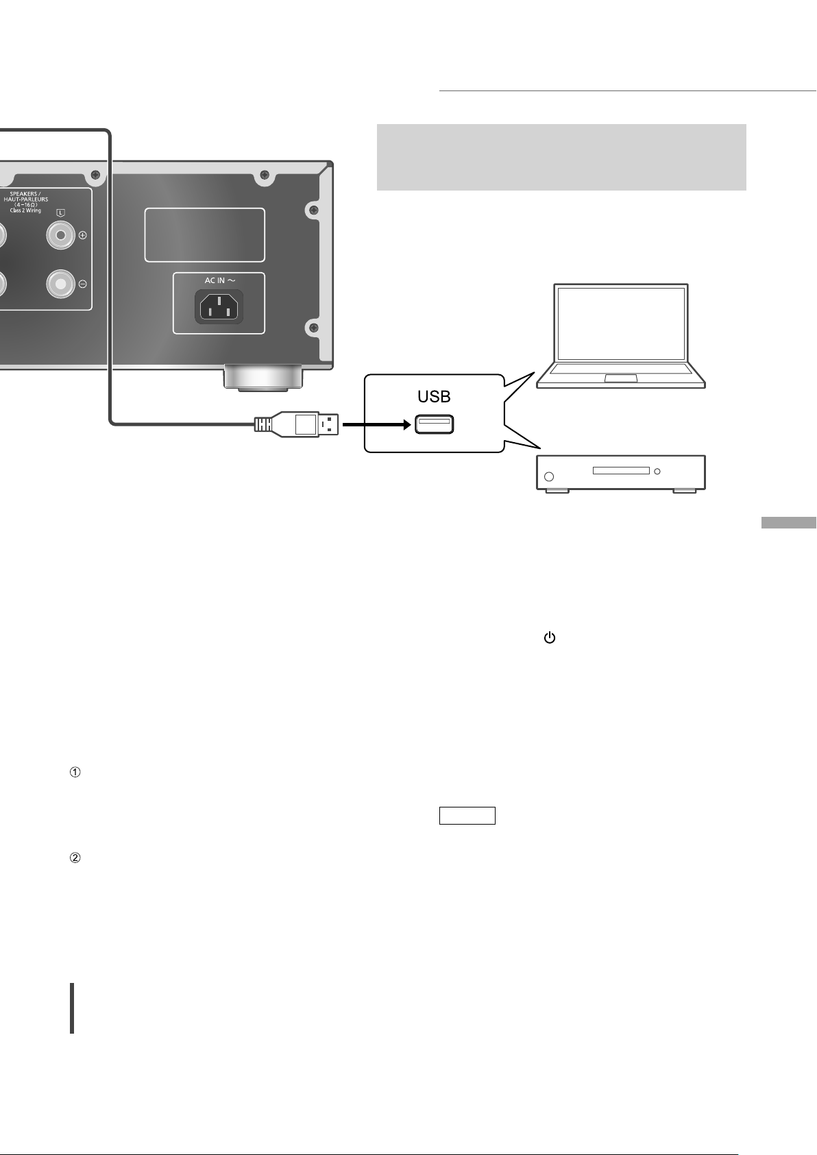
Using PC, etc.
You can connect the PC, etc. or another device with
USB 2.0 cable (not supplied) to this unit and play back
music.
PC, etc.
■ Preparation
Connecting to a PC
• Before connecting to a PC, follow the steps
below.
• Refer to the following for the recommend OS
versions for your PC (as of February 2017):
- Windows 7, Windows 8, Windows 8.1,
Windows 10
- OS X 10.7, 10.8, 10.9, 10.10, 10.11,
macOS 10.12
Download and install the dedicated USB driver
to the PC. (Only for Windows OS)
• Download and install the driver from the
website below.
www.technics.com/support/
Download and install the dedicated app
“Technics Audio Player” (free of charge) on
your PC.
• Download and install the app from the
website below.
www.technics.com/support/
Using USB 2.0 cable
Audio device with USB-DAC output
terminal such as ST-G30, etc.
3 Connect the AC power supply cord to
this unit. ( 15)
4 Press [AMP
] to turn this unit on.
5 Press [>INPUT<] repeatedly to select
“PC”.
• You can also select the input source by
turning the input selector knob on the unit.
6 Start playback using the dedicated
app “Technics Audio Player” on the
connected PC.
Note
• When connecting an audio device with USB-
DAC output terminal such as ST-G30, etc., refer
to the operating instructions of the connected
device.
• About supported format, refer to “Format
support”. ( 35)
• Windows is a trademark or a registered
trademark of Microsoft Corporation in the
United States and other countries.
• Mac and OS X are trademarks of Apple Inc.,
registered in the U.S. and other countries.
• macOS is a trademark of Apple Inc.
English
1 Disconnect the AC power supply cord.
2 Connect this unit and a PC, etc.
Operations
(17)
17
Page 18
Operations
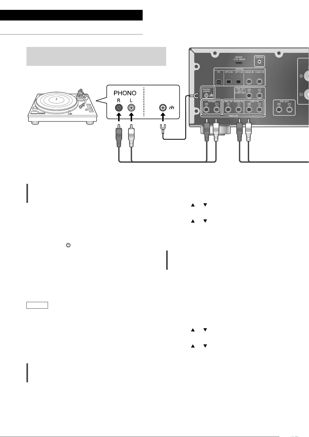
Using turntable (PHONO)
You can connect the turntable with PHONO cable (not
supplied) to this unit and play back music.
PHONO
EARTH
Turntable
PHONO earth lead
(not supplied)
PHONO cable (not supplied)
Using PHONO cable
1 Disconnect the AC power supply cord.
2 Connect this unit and a turntable.
3 Connect the AC power supply cord to
this unit. ( 15)
4 Press [AMP
5 Press [>INPUT<] repeatedly to select
“PHONO”.
• You can also select the input source by
turning the input selector knob on the unit.
6 Start playback on the connected
turntable.
Note
• When connecting a turntable with a built-in
PHONO equalizer, connect the PHONO cable
to the analog audio input terminals (LINE1 IN or
LINE2 IN) of this unit. ( 19)
• When connecting a turntable with a PHONO
earth lead, connect the PHONO earth lead to
the PHONO EARTH terminal of this unit.
] to turn this unit on.
1 Press [AMP].
2 Press [MENU].
3 Press [
], [ ] repeatedly to select
“Attenuator” and then press [OK].
4 Press [
], [ ] to select “On(-3dB)”/
”On(-6dB)”/”On(-10dB)” and then
press [OK].
Reducing low frequency noise
Reduces the low frequency noise caused by the
warpage of record.
• The factory default is “Off”.
• You can also set this menu while “LINE1” or
“LINE2” is selected as input source of this unit.
1 Press [AMP].
2 Press [MENU].
3 Press [
“Subsonic Filter” and then press [OK].
4 Press [
press [OK].
], [ ] repeatedly to select
], [ ] to select “On” and then
Minimizing sound distortion
If sound distortion occurs when using the analog
audio input terminals, setting the attenuator to
“On(-3dB)”/”On(-6dB)”/”On(-10dB)” may improve
the sound quality.
• The factory default is “Off”.
(18)
18
Page 19
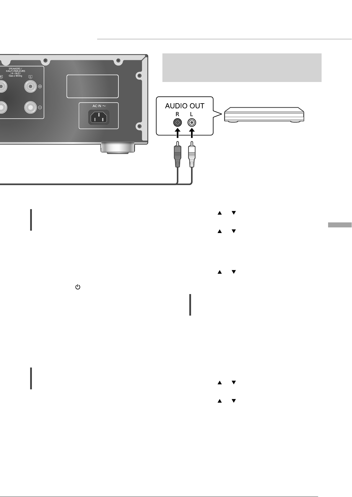
Using analog audio output device (LINE1/LINE2)
Analog audio cable (not supplied)
You can connect the Blu-ray Disc player, etc. with
analog audio cable (not supplied) to this unit and play
back music.
Blu-ray Disc player, etc.
Using analog audio cable
1 Disconnect the AC power supply cord.
2 Connect this unit and a Blu-ray Disc
player, etc.
3 Connect the AC power supply cord to
this unit. ( 15)
4 Press [AMP
] to turn this unit on.
5 Press [>INPUT<] repeatedly to select
“LINE1” or “LINE2”.
• You can also select the input source by
turning the input selector knob on the unit.
• Set to “LINE2” (see below) when “MAIN IN”
is displayed as input source of this unit.
6 Start playback on the connected
device.
When connecting to “LINE2”
Analog audio input terminals (LINE2 IN/MAIN IN)
have both LINE2 IN and MAIN IN functions.
When connecting an analog audio output device,
switch the input setting of this unit to “LINE2”.
• The factory default is “LINE2”.
4 Press [
], [ ] repeatedly to select
“Input Mode” and then press [OK].
5 Press [
], [ ] repeatedly to select
“LINE2” and then press [OK].
• The volume level set after switching to
“LINE2” is displayed. Confirm and adjust the
volume before pressing [OK].
6 Press [ ], [ ] to select “Yes” and then
press [OK].
Minimizing sound distortion
If sound distortion occurs when using the analog
audio input terminals, setting the attenuator to
“On” may improve the sound quality.
• The factory default is “Off”.
1 Press [AMP].
2 Press [MENU].
3 Press [
“Attenuator” and then press [OK].
4 Press [
press [OK].
], [ ] repeatedly to select
], [ ] to select “On” and then
English
1 Press [AMP].
2 Press [>INPUT<] repeatedly to select
“MAIN IN”.
3 Press [MENU].
Operations
(19)
19
Page 20
Operations
Using this unit as power amplifier
You can connect the AV receiver, control amplifier, etc. with
analog audio cable (not supplied) to this unit and use this unit as
power amplifier.
AV receiver, control
amplifier, etc.
Set the volume of the AV receiver,
control amplifier, etc. to minimum before
connecting.
While using this unit as power amplifier,
the volume adjustment with this unit is
disabled. Adjust the volume little by little
with the connected device.
Do not input the audio signal from PRE
OUT/LINE OUT terminals to the MAIN IN
terminals of this unit. Doing so may cause
malfunction.
Analog audio cable
(not supplied)
Using analog audio cable
1 Disconnect the AC power supply cord.
2 Connect this unit and AV receiver,
control amplifier, etc. after minimizing
the volume of the device.
3 Connect the AC power supply cord to
this unit. ( 15)
4 Press [AMP
5 Press [>INPUT<] repeatedly to select
“LINE2”.
• You can also select the input source by
turning the input selector knob on the unit.
6 Press [AMP].
] to turn this unit on.
20
(20)
7 Press [MENU].
8 Press [
], [ ] repeatedly to select
“Input Mode” and then press [OK].
9 Press [
], [ ] to select “MAIN IN” and
press [OK].
Page 21
10 Confirm the displayed message and
press [OK].
English
Minimizing sound distortion
11 Press [
], [ ] to select “Yes” and then
press [OK].
12 Start playback on the connected
device.
Note
• It is not possible to adjust the volume with this
unit.
• Sound is not output from headphones jack and
PRE OUT terminals.
• Select “LINE2” when not using this unit as
power amplifier. ( 19)
• When the input source is switched to “LINE2”
or other source from “MAIN IN” and the current
volume level is higher than previous level, the
volume is automatically adjusted.
If sound distortion occurs, setting the attenuator
to “On” may improve the sound quality.
• The factory default is “Off”.
1 Press [AMP].
2 Press [MENU].
3 Press [
], [ ] repeatedly to select
“Attenuator” and then press [OK].
4 Press [
], [ ] to select “On” and then
press [OK].
Operations
(21)
21
Page 22
Operations
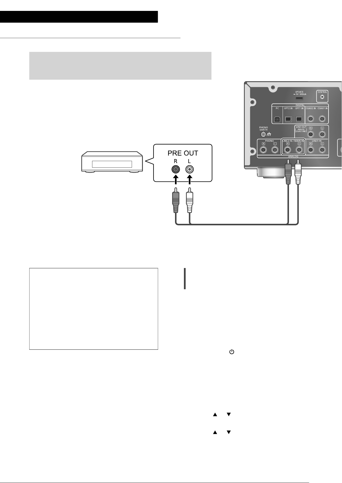
Connecting a power amplifier, subwoofer, etc.
You can connect the power amplifier, subwoofer, etc.
with analog audio cable (not supplied) to output the
analog audio signals.
Power amplifier,
Subwoofer, etc.
Do not input the audio signal from PRE
OUT/LINE OUT terminals to the analog
audio input terminals of this unit. Doing so
may cause malfunction.
Using analog audio cable
1 Disconnect the AC power supply cord.
2 Connect this unit and a power
amplifier, subwoofer, etc.
3 Connect the AC power supply cord to
this unit. ( 15)
4 Press [AMP
Note
• For details, refer to the operating instructions of
the connected device.
• Sound is not output from PRE OUT terminals
while “MAIN IN” is selected as input source of
this unit.
] to turn this unit on.
Analog audio cable (not supplied)
Setting the audio output (PRE OUT)
You can set the audio output of the speaker
output terminals and PRE OUT terminals.
1 Press [AMP].
2 Press [SETUP].
3 Press [
“PRE OUT” and then press [OK].
4 Press [
setting and then press [OK].
• The factory default is “On”.
• Not available when “MAIN IN” is selected as
input source of this unit.
On:
Sound is output from the speaker output
terminals and PRE OUT terminals.
On (Speaker:Off):
Sound is not output from the speaker output
terminals. Sound is output from PRE OUT
terminals.
Off:
Sound is not output from PRE OUT terminals.
Sound is output from the speaker output
terminals.
], [ ] repeatedly to select
], [ ] to select the output
22
Note
• It is recommended to set to “On (Speaker:Off)”
(rated output: 1 V) when connecting a power
amplifier.
(22)
Page 23

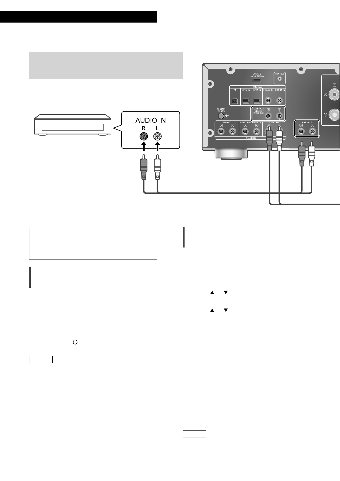
Using analog audio input device
You can connect the CD recorder, etc. with analog
audio cable (not supplied) to output analog audio
signals from this unit (LINE1/LINE2/PHONO).
CD recorder, etc.
Analog audio cable (not supplied)
Do not input the audio signal from PRE
OUT/LINE OUT terminals to the analog
audio input terminals of this unit. Doing so
may cause malfunction.
Using analog audio cable
1 Disconnect the AC power supply cord.
2 Connect this unit and a CD recorder,
etc.
3 Connect the AC power supply cord to
this unit. ( 15)
4 Press [AMP
Note
• When a digital audio signal (COAX1/COAX2/
OPT1/OPT2/PC) is selected as input source of
this unit, analog audio signal (LINE1) is output.
• The choppy audio occurs in output audio signal
when switching the input source.
] to turn this unit on.
English
Operations
(23)
23
Page 24

Settings
Sound adjustment, Other settings
The sound effects and other settings can be set up.
1 Press [AMP].
2 Press [SETUP].
3 Press [
], [ ] repeatedly to
select the menu and then
press [OK].
4 Press [
], [ ], [ ], [ ] to select
a desired item or value, and
press [OK].
Language setting
“Language”
Select “English” or “Français” for the display.
• The factory default is “English”.
Adjusting BASS/MID/TREBLE
“Tone Control”
You can adjust the tone of this unit. Each tonal
range (BASS/MID/TREBLE) can be adjusted.
• To enable this function, select “On
(adjustment)”.
• Each level can be adjusted between “-10” and
“+10”.
• “TONE” is displayed after setting.
• While connecting Technics device supporting
system control function (Network Audio
Player, etc.) to this unit, sound setting on the
connected device may have a priority over this
unit. Adjust the sound with the connected
device.
• Not available when using this unit as power
amplifier ( 20). Adjust the sound with the AV
receiver, control amplifier, etc.
Adjusting the volume attenuator
“VOLUME Attenuator”
Set to “On (-20dB)” for the attenuator to ease
the volume adjustment at a low volume.
• The factory default is “Off”.
• ”ATT” is displayed after setting.
• Not available when using this unit as power
amplifier ( 20). Adjust the sound with the AV
receiver, control amplifier, etc.
24
(24)
Page 25

English
Auto off function
“AUTO OFF”
This unit is designed to conserve its power
consumption and save energy. The unit has been
left unused for about 20 minutes and will enter
standby mode within a minute. Press any button
to cancel it.
• The factory default is “Off”.
• “AUTO OFF” is displayed 3 minutes before this
unit is turned off.
Note
• The setting is stored even if the power is turned
off and on.
Displaying the volume status
“VOLUME Display”
The volume status is displayed when adjusting
the volume.
• The factory default is “Off”.
• Not available when “MAIN IN” is selected as
input source of this unit.
Checking the model name
“Model No.”
The model name is displayed.
Checking the firmware version
“F/W Version”
The version of the installed firmware is displayed.
Settings
(25)
25
Page 26

Settings
Using output correction function (LAPC)
You can make the optimum adjustment according to your own speakers.
Measuring the output signal of the
amplifier and correcting its output
(LAPC)
■ Preparation
• Disconnect the headphones.
Test tone emitted during measurement
To ensure the measurement accuracy,
the speakers output a test tone at regular
intervals. (For approximately 3 minutes)
It is not possible to change the volume of the
audio being output while the measurement is
in progress.
1 Press [AMP ] to turn this unit on.
2 Press and hold [LAPC] until “Please
Wait” is displayed.
“LAPC Measuring” is displayed and this unit
will start measuring the output signal of the
amplifier. Check that a test tone is output from
both the left and right speakers.
When the measurement is complete, amplifier
output correction will be automatically turned
on.
• If you press [LAPC] while the measurement is
in progress, it will be cancelled.
• If you connect headphones during amplifier
signal measurement or amplifier output
correction, it will be cancelled.
■ Turning on/off the output correction
function
Press [LAPC] to select “On”/“Off”.
• LAPC indicator lights and “LAPC : On” is
displayed while the output correction function
is in progress.
Note
• Measurement is not available for the audio
output signal from PRE OUT terminals of this
unit. ( 22)
• Depending on the type of the connected
speakers, the effect of the output correction
function may be minimal.
• The corrected output remains in effect until you
measure the output signal again. When you use
other speakers, redo the measurement.
26
(26)
Page 27

Firmware updates
Firmware updates
“F/W Update”
Occasionally, Panasonic may release updated
firmware for this unit that may add or improve
the way a feature operates. These updates are
available free of charge.
• For the update information, refer to the
following website.
www.technics.com/support/firmware/
Downloading takes approx. 3 minutes.
Do not disconnect the AC power supply
cord or turn this unit to standby while
updating.
Do not disconnect the USB flash memory
while updating.
• The progress is displayed as “Updating
while updating. (“ ” stands for a number.)
Note
• During the update process, no other operations
can be performed.
• If there are no updates, “Firmware is Up To
Date” is displayed. (No need to update it.)
• Updating the firmware may reset the settings
of this unit.
%”
■ Preparation
• Download the latest firmware on the USB flash
memory. For details, refer to the following
website.
www.technics.com/support/firmware/
1 Connect the USB flash memory with
new firmware.
2 Press [AMP].
3 Press [SETUP].
4 Press [
“F/W Update” and then press [OK].
5 Press [
press [OK].
• The progress is displayed as “Updating %”
while updating. (“ ” stands for a number.)
• When the update has finished successfully,
“Success” is displayed.
], [ ] repeatedly to select
], [ ] to select “Yes” and then
English
6 Disconnect the AC power supply cord
and USB flash memory, and reconnect
it after 3 minutes.
Note
• Downloading may take longer depending on
the USB flash memory.
• Use a USB flash memory with FAT16 or FAT32
format.
• UPDATE terminal is used only for firmware
updating. Do not connect any USB device
other than the USB flash memory for firmware
updating.
• No USB device can be charged from the
UPDATE terminal of this unit.
Settings
(27)
27
Page 28

Settings
System control connection
You can operate this unit and Technics devices supporting
system control function (Network Audio Player, Compact Disc
Player, etc.) simultaneously with ease on the remote control.
For details, refer to the operating instructions of each device.
Network Audio Player, etc.
Using system connection cable and
audio cable
1 Disconnect the AC power supply cord.
2 Connect this unit and Technics device
supporting system control function
(Network Audio Player, etc.).
• Use both of the system connection cable and
the audio cables when connecting this unit
and the device.
• Use the system connection cable supplied
with the connected device.
3 Connect the AC power supply cord to
this unit. ( 15)
4
Press [AMP
5 Press [AMP].
6 Press [SETUP].
7 Press [
“System Control” and then press [OK].
] to turn this unit on.
], [ ] repeatedly to select
System connection cable
Coaxial digital cable
(not supplied)
*
8 Press [ ], [ ] to select the input
source for the device which is
connected at step 2, and press [OK].
• Select “Off” to disable the system control
function.
: The illustration shows the example when
*
connecting with coax digital cable. Connect
the device with proper cable/terminal
supporting the device.
Note
• When using the system control function by
connecting the Technics device to the LINE2 IN
terminal of this unit, select “LINE2” ( 19) for
the input setting of the analog audio input
terminals (LINE2 IN/MAIN IN) of this unit.
• When using this unit as power amplifier ( 20),
the system control function for the Technics
device connected to the MAIN IN terminals is
disabled.
28
(28)
Page 29

English
Switching this unit and the
connected device
• If you point the remote control at this unit
and press [AMP ] when this unit and the
connected device are in standby mode, this
unit and the device of the selected input source
which is set with “System Control” will be
turned on simultaneously.
• If you point the remote control at this unit
and press [AMP
connected device are turned on, this unit and
the connected device will enter standby mode.
• You can also switch this unit and the connected
device by pressing the standby/on button on
this unit.
] when this unit and the
Switching this unit’s input source
automatically
When you perform an operation such as
playback on the connected device, the input
source of this unit will be automatically switched
to the source which is set with “System Control”.
Settings
(29)
29
Page 30

Troubleshooting
Before requesting service, make the following checks. If you are uncertain about some of the check
points, or if the solutions indicated in the following guide do not resolve the issue, then consult your
dealer for instructions.
Heat buildup of this unit
This unit becomes warm while in use. This is not
a malfunction.
Do you have the latest firmware
installed?
Panasonic is constantly improving the unit’s
firmware to ensure that our customers are
enjoying the latest technology. ( 27)
To restore all settings to the factory
defaults
When the following situations occur, reset the
memory:
• There is no response when buttons are pressed.
• You want to clear and reset the memory
contents.
1 Press [AMP].
2 Press [SETUP].
3 Press [
“Initialization” and then press [OK].
• A confirmation screen appears. Select “Yes”
in the following steps to restore all the
settings to defaults.
4 Press [ ], [ ] to select “Yes” and then
press [OK].
5 Press [
press [OK] again.
], [ ] repeatedly to select
], [ ] to select “Yes” and then
General
The unit does not work.
Operations are not done properly.
• One of the unit’s safety devices may have been
activated.
Press [ ] on the unit to switch the unit to
standby.
• If the unit does not switch to standby,
disconnect the AC power supply cord, wait
for at least 3 minutes, then reconnect it.
Press [ ] on the unit to switch on. If the
unit still cannot be operated, consult the
dealer.
A “humming” sound can be heard during
playback.
• An AC power supply cord of another device
or fluorescent light is near the cables. Turn off
other appliances, or keep them away from the
cables of this unit.
• A strong magnetic field near a TV or other
device may adversely affect the audio quality.
Keep this unit away from such a location.
• The speakers may output noise when a device
nearby is emitting powerful radio waves, such
as when a mobile phone is on a call.
No sound.
• Check the volume of this unit and the
connected device.
• Check connections to speakers and other
equipment.
• Connect speakers and measure the output
signal of the amplifier. ( 26)
• Check the impedance of the connected
speakers.
• Check to see if the correct input source is
selected.
• Insert the plugs of the cables to be connected
all the way in.
• Confirm the sound output setting. (Sound is
not output from the speakers connected to the
speaker output terminals of this unit while “PRE
OUT” is set to “On (Speaker:Off)”.) ( 22)
• Playback of multi-channel content is not
supported.
• The digital audio input terminals of this unit can
only detect linear PCM signals. For details, refer
to the operating instructions of the device.
30
(30)
Page 31

Sound is distorted.
• Setting “Attenuator” to “On” according to the
analog audio input may minimize the sound
distortion. ( 18, 19, 21)
• Setting the attenuator is not available for the
output audio signal from LINE OUT terminal.
The volume is automatically changed.
• When the input source is switched to “LINE2”
or other source from “MAIN IN” and the current
volume level is higher than previous level, the
volume is automatically adjusted. (Volume knob
automatically turns.) ( 20)
The unit turns to standby mode
automatically.
• Is the auto off function turned on? ( 25)
• This unit incorporates a protection circuit
to prevent damage caused by heat buildup.
When you use this unit at a high volume
level for a long period of time, it may turn
off automatically. Wait for this unit to cool
down before turning on this unit again. (For
approximately 3 minutes)
The settings are reset to the factory defaults.
• Updating the firmware may reset the settings.
The peak power meter does not operate.
• In the following cases, this meter does not
operate:
- When the headphones are connected.
- When the peak power meter light is turned
off by pressing [DIMMER].
- When this unit is muted by pressing [MUTE].
- When “PRE OUT” is set to “On (Speaker:Off)”
( 22)
The system control function is not working.
• Use the system connection cable supplied with
the connected device.
• Connect the system connection cable to the
system terminals (CONTROL). ( 28)
• Check the connection of system connection
cable, audio cable and the input source which is
set with “System Control”. ( 28)
• Connect Technics device supporting system
control function (Network Audio Player,
Compact Disc Player, etc.) to this unit. For
details, refer to the following website.
www.technics.com/support/
PC
The PC does not recognize this unit.
• Check your operating environment. ( 17)
• Restart the PC, turn this unit to standby and on,
and then reconnect the USB cable.
• Use another USB port of the connected PC.
• Install the dedicated USB driver if using a PC
with Windows. ( 17)
Remote control
The remote control does not work properly.
• The batteries are depleted or inserted
incorrectly. ( 12)
• To avoid interference, please do not put any
objects in front of signal sensor. ( 10)
• If the remote control mode of the remote
control differs from that of this unit, match the
mode of the remote control to the mode of this
unit. ( 13)
English
Troubleshooting
(31)
31
Page 32

Troubleshooting
Messages
ATTENTION : MAX Output Setting
• While using this unit as power amplifier, the
volume adjustment with this unit is disabled.
• Adjust the volume little by little with the
connected device. ( 20)
AUTO OFF
• The unit has been left unused for about 20
minutes and will shut down within a minute.
Press any button to cancel it. ( 25)
Connect USB Device
• The firmware download has failed.
• Download the latest firmware on the USB flash
memory and try again. ( 27)
Disconnect PHONES
• When the headphones are connected,
measuring the output signal of the amplifier
(LAPC) will not start.
• Disconnect the headphones.
• If you connect headphones during amplifier
signal measurement or amplifier output
correction, it will be cancelled. ( 26)
” (“ ” stands for a number.)
“F
• An abnormality has occurred. (If this unit
detects an abnormality, the protection circuit
is activated, and the power may be turned off
automatically.)
- Is the volume extremely high? Or is this unit
placed in an extremely hot place?
Wait a few seconds and then turn the unit
on again. (The protection circuit will be
deactivated.)
Load Fail
• The firmware cannot be found on the USB flash
memory.
• Download the latest firmware on the USB flash
memory and try again. ( 27)
No Device
• USB flash memory with new firmware is not
connected.
Connect the USB flash memory with new
firmware. ( 27)
Not Measured
• Measuring the output signal for the output
correction function (LAPC) has not been done
yet.
• Measure the output signal. ( 26)
Not Valid
• The function you have tried to use is not
available with the current settings. Check the
steps and settings.
PHONES Connected
• The headphones are connected.
• Sound is not output from headphones jack and
speaker output terminals when the headphones
are connected and “MAIN IN” is selected as
input source of this unit. ( 20)
“Remote
• The remote control and this unit are using
different modes.
Change the mode on the remote control. ( 13)
Signal Overflow
• The sound from the analog audio input
terminals in use is distorted. Select ”Attenuator”
according to the selected analog audio input,
and change the setting of the attenuator to
“On”. ( 19)
Unlocked
• “COAX1”, “COAX2”, “OPT1”, “OPT2” or “PC” is
selected, but no device is connected. Check the
connection with the device. ( 16, 17)
• The sampling frequency components, etc. of
the audio signals are not input correctly.
- About supported format, refer to “Format
support”. ( 35)
USB Over Current Error
USB device is drawing too much power.
• Disconnect the USB device and connect it
again. ( 27)
• Turn the unit to standby and on again.
VOLUME
• When the input source is switched to “LINE2”
or other source from “MAIN IN”, the volume
level after switching the input source is
displayed.
• Confirm and adjust the volume before pressing
[OK].
” (“ ” stands for a number.)
OK (“ ” stands for a number.)
32
(32)
Page 33

Others
Unit care
• Pull out the AC power supply cord from the
outlet before maintenance. Clean this unit with
a soft cloth.
• When dirt is heavy, wring a wet cloth tightly to
wipe the dirt, and then wipe it with a soft cloth.
• Do not use solvents including benzine, thinner,
alcohol, kitchen detergent, a chemical wiper,
etc. This might cause the exterior case to be
deformed or the coating to come off.
To dispose or transfer this unit
• This unit may contain private information.
Before disposing of or transferring this unit,
perform the following to delete the data,
including personal or secret information.
• “To restore all settings to the factory defaults”
( 30)
English
Troubleshooting / Others
(33)
33
Page 34

Others
Specifications
■ GENERAL
Power supply AC 120 V, 60 Hz
Power
consumption
Power
consumption in
standby mode
Dimensions
(W×H×D)
Mass Approx. 12.3 kg (27.2 lbs)
Operating
temperature range
Operating humidity
range
■ AMPLIFIER SECTION
FTC output power
Load impedance 4 - 16
Frequency
response
PHONO (MM)
LINE
DIGITAL
Input sensitivity/
Input impedance
PHONO (MM) 2.5 mV / 47 k
LINE 200 mV / 22 k
85 W
Approx. 0.3 W
15
430 mm (16
148 mm (5 13/16”) ×
428 mm (16
0 °C to +40 °C
(+32 °F to +104 °F)
35 % to 80 % RH
(no condensation)
70 W + 70 W
(1 kHz, T.H.D. 0.5 %, 8 ,
20 kHz LPF)
140 W + 140 W
(1 kHz, T.H.D. 0.5 %, 4 ,
20 kHz LPF)
20 Hz to 20 kHz
(RIAA DEVIATION ±1 dB,
8 )
5 Hz to 80 kHz
(-3 dB, 8 )
5 Hz to 90 kHz
(-3 dB, 8 )
/16”) ×
27
/32”)
■ TERMINALS SECTION
Headphones Jack
PC
Analog input
LINE IN ×2 Pin jack
PHONO (MM) Pin jack
Digital input
OPT IN ×2 Optical terminal
COAX IN ×2 Pin jack
Format support LPCM
Analog output
LINE OUT Pin jack
PRE OUT Pin jack
System port
System control 3.5 mm (
Stereo, 6.3 mm (
0.75 mW, 32
REAR USB
Type B Connector
■ FORMAT SECTION
USB-B
USB 2.0 high-speed
USB Standard
DSD control mode
USB Audio Class 2.0,
Asynchronous mode
ASIO Native mode,
DoP mode
1
/8”), Jack
1
/4”)
34
(34)
Page 35

■ Format support
This unit supports the following formats.
• Playback of all formats supported by this unit is not guaranteed.
• Playback of a format not supported by this unit may cause choppy audio or noise. In such cases, check to
see if this unit supports the format.
• File information (sampling frequency, etc.) shown by this unit and playback software may differ from each
other.
PC (USB-B)
File format Sampling frequency
PCM 32/44.1/48/88.2/96/176.4/192/352.8/384 kHz 16/24/32 bit
DSD 2.8 MHz/5.6 MHz/11.2 MHz
: If you download and install the dedicated app, you can play back files in wide-ranging formats. ( 17)
*
For details, refer to the operating instructions of the app.
Note
• Specifications are subject to change without notice.
• Mass and dimensions are approximate.
• DSD is a trademark of Sony Corporation.
*
Bit rate / Number of
quantization bits
English
Others
(35)
35
Page 36

Others
Limited Warranty (ONLY FOR U.S.A.)
Technics Products – Limited Warranty
Limited Warranty Coverage
(For USA Only)
If your product does not work properly because of a defect
in materials or workmanship, Panasonic Corporation of North
America (referred to as “the warrantor”) will, for the length
of the period indicated on the chart below, which starts with
the date of original purchase (“warranty period”), at its option
either (a) repair your product with new or refurbished parts,
(b) replace it with a new or a refurbished equivalent value
product, or (c) refund your purchase price. The decision to
repair, replace or refund will be made by the warrantor.
Product or Part Name Parts Labor
Stereo Integrated Amplifier
Technics Music Server
Technics CD Stereo System
3 (three)
years
Technics Turntable System
During the “Labor” warranty period there will be no charge
for labor. During the “Parts” warranty period, there will be
no charge for parts. This Limited Warranty excludes both
parts and labor for non-rechargeable batteries, antennas,
and cosmetic parts (cabinet). This warranty only applies to
products purchased and serviced in the United States. This
warranty is extended only to the original purchaser of a new
product which was not sold “as is”.
Mail-In Service--Online Repair Request
Online Repair Request
To submit a new repair request and for quick repair status visit
our Web Site at
http://shop.panasonic.com/support
When shipping the unit, carefully pack, include all supplied
accessories listed in the Owner’s Manual, and send it prepaid,
adequately insured and packed well in a carton box. When
shipping Lithium Ion batteries please visit our Web Site at
http://shop.panasonic.com/support as Panasonic is committed
to providing the most up to date information. Include a
letter detailing the complaint, a return address and provide
a daytime phone number where you can be reached. A valid
registered receipt is required under the Limited Warranty.
IF REPAIR IS NEEDED DURING THE WARRANTY PERIOD,
THE PURCHASER WILL BE REQUIRED TO FURNISH A
SALES RECEIPT/PROOF OF PURCHASE INDICATING
DATE OF PURCHASE, AMOUNT PAID AND PLACE OF
PURCHASE. CUSTOMER WILL BE CHARGED FOR THE
REPAIR OF ANY UNIT RECEIVED WITHOUT SUCH PROOF
OF PURCHASE.
Limited Warranty Limits and Exclusions
This warranty ONLY COVERS failures due to defects in
materials or workmanship, and DOES NOT COVER normal
wear and tear or cosmetic damage. The warranty ALSO DOES
NOT COVER damages which occurred in shipment, or failures
which are caused by products not supplied by the warrantor,
or failures which result from accidents, misuse, abuse, neglect,
mishandling, misapplication, alteration, faulty installation,
set-up adjustments, misadjustment of consumer controls,
improper maintenance, power line surge, lightning damage,
modification, introduction of sand, humidity or liquids,
commercial use such as hotel, office, restaurant, or other
business or rental use of the product, or service by anyone
other than a Factory Service Center or other Authorized
Servicer, or damage that is attributable to acts of God.
The model number and serial number of this product can
be found on either the back or the bottom of the unit.
Please note them in the space provided below and keep for
future reference.
MODEL NUMBER SU-G700
SERIAL NUMBER
(36)
36
3 (three)
years
THERE ARE NO EXPRESS WARRANTIES EXCEPT AS
LISTED UNDER “LIMITED WARRANTY COVERAGE”.
THE WARRANTOR IS NOT LIABLE FOR INCIDENTAL OR
CONSEQUENTIAL DAMAGES RESULTING FROM THE USE
OF THIS PRODUCT, OR ARISING OUT OF ANY BREACH OF
THIS WARRANTY.
(As examples, this excludes damages for lost time, travel to
and from the servicer, loss of or damage to media or images,
data or other memory or recorded content. The items listed
are not exclusive, but for illustration only.)
ALL EXPRESS AND IMPLIED WARRANTIES, INCLUDING
THE WARRANTY OF MERCHANTABILITY, ARE LIMITED
TO THE PERIOD OF THE LIMITED WARRANTY.
Some states do not allow the exclusion or limitation of
incidental or consequential damages, or limitations on how
long an implied warranty lasts, so the exclusions may not
apply to you.
This warranty gives you specific legal rights and you may also
have other rights which vary from state to state. If a problem
with this product develops during or after the warranty
period, you may contact your dealer or Service Center. If the
problem is not handled to your satisfaction, then write to:
Consumer Affairs Department
Panasonic Corporation of North America
661 Independence Pkwy
Chesapeake, VA 23320
PARTS AND SERVICE, WHICH ARE NOT COVERED BY THIS
LIMITED WARRANTY, ARE YOUR RESPONSIBILITY.
for all your Technics gear
Go to
http://shop.panasonic.com/support
Get everything you need to get the most out of
your Technics products
Accessories & Parts for your Camera, Phone, A/V
products, TV, Computers & Networking, Personal
Care, Home Appliances, Headphones, Batteries,
Backup Chargers & more…
Customer Services Directory
For Product Information, Operating Assistance,
Parts, Owner’s Manuals, Dealer and Service info
go to http://shop.panasonic.com/support
For the hearing or speech impaired TTY: 1- 877-833-8855
As of December 2015
User memo:
DATE OF PURCHASE
DEALER NAME
DEALER ADDRESS
TELEPHONE NUMBER
Page 37

Limited Warranty (ONLY FOR CANADA)
Panasonic Canada Inc.
Panasonic Canada Inc. warrants this product to be free from defects in material and workmanship under normal use and
for a period as stated below from the date of original purchase agrees to, at its option either (a) repair your product with
new or refurbished parts, (b) replace it with a new or a refurbished equivalent value product, or (c) refund your purchase
price. The decision to repair, replace or refund will be made by Panasonic Canada Inc.
Stereo Integrated Amplifier 3 (three) years parts and labour
Technics Music Server 3 (three) years parts and labour
Technics CD Stereo System 3 (three) years parts and labour
Technics Turntable System 3 (three) years parts and labour
This warranty is given only to the original purchaser, or the person for whom it was purchased as a gift, of a Technics
brand product mentioned above sold by an authorized Panasonic dealer in Canada and purchased and used in Canada,
which product was not sold “as is”, and which product was delivered to you in new condition in the original packaging.
IN ORDER TO BE ELIGIBLE TO RECEIVE WARRANTY SERVICE HEREUNDER, A PURCHASE RECEIPT OR OTHER
PROOF OF DATE OF ORIGINAL PURCHASE, SHOWING AMOUNT PAID AND PLACE OF PURCHASE IS REQUIRED
LIMITATIONS AND EXCLUSIONS
This warranty ONLY COVERS failures due to defects in materials or workmanship, and DOES NOT COVER normal
wear and tear or cosmetic damage. The warranty ALSO DOES NOT COVER damages which occurred in shipment, or
failures which are caused by products not supplied by Panasonic Canada Inc., or failures which result from accidents,
misuse, abuse, neglect, mishandling, misapplication, alteration, faulty installation, set-up adjustments, misadjustment
of consumer controls, improper maintenance, power line surge, lightning damage, modification, introduction of sand,
humidity or liquids, commercial use such as hotel, office, restaurant, or other business or rental use of the product, or
service by anyone other than an Authorized Servicer, or damage that is attributable to acts of God.
Dry cell batteries are also excluded from coverage under this warranty.
THIS EXPRESS, LIMITED WARRANTY IS IN LIEU OF ALL OTHER WARRANTIES, EXPRESS OR IMPLIED, INCLUDING
ANY IMPLIED WARRANTIES OF MERCHANTABILITY AND FITNESS FOR A PARTICULAR PURPOSE. IN NO EVENT WILL
PANASONIC CANADA INC. BE LIABLE FOR ANY SPECIAL, INDIRECT OR CONSEQUENTIAL DAMAGES RESULTING
FROM THE USE OF THIS PRODUCT OR ARISING OUT OF ANY BREACH OF ANY EXPRESS OR IMPLIED WARRANTY. (As
examples, this warranty excludes damages for lost time, travel to and from the Authorized Servicer, loss of or damage to
media or images, data or other memory or recorded content. This list of items is not exhaustive, but for illustration only.)
In certain instances, some jurisdictions do not allow the exclusion or limitation of incidental or consequential damages,
or the exclusion of implied warranties, so the above limitations and exclusions may not be applicable. This warranty gives
you specific legal rights and you may have other rights which vary depending on your province or territory.
WARRANTY SERVICE
For product operation, repairs and information assistance, please visit our Support page on:
Carefully pack and send prepaid, adequately insured and preferably in the original carton.
Include details of the defect claimed, and proof of date of original purchase.
5770 Ambler Drive, Mississauga, Ontario L4W 2T3
TECHNICS PRODUCT – LIMITED WARRANTY
www.panasonic.ca/english/support
IF YOU SHIP THE PRODUCT TO A SERVICENTRE
English
Others
(37)
37
Page 38

Nous vous remercions d’avoir arrêté votre choix sur cet appareil.
Il est recommandé de lire attentivement ce manuel avant d’utiliser l’appareil et de le conserver pour
consultation ultérieure.
• À propos des illustrations dans le présent manuel
- Les pages à consulter sont indiquées par “ ○○”.
- Les illustrations peuvent être différentes de l’apparence réelle de l’appareil.
Pour toute assistance supplémentaire, visiter :
États-Unis : http://shop.panasonic.com/support
Canada : www.panasonic.ca/french/support
Inscrivez-vous en ligne sur le site :
http://shop.panasonic.com/support (clients situés aux États-Unis uniquement)
Caractéristiques
Technologies audio de haute qualité
incluant le circuit numérique JENO
et le LAPC
Le circuit JENO transmet et traite les signaux
audio entièrement au format numérique avec
un minimum de gigue, depuis l’étage d’entrée
jusqu’à l’étage de puissance. Le LAPC dirige
l’étalonnage de la phase adaptative de la charge
de l’enceinte afin d’obtenir un gain et des
spécifications de phase idéaux pour tout type
d’enceinte. En outre, un circuit de conversion de
modulation d’impulsions en durée (MID) unique,
de haute précision, est utilisé pour la conversion
de modulation d’impulsions en durée (MID), très
importante pour la qualité du son.
Configuration en trois sections
Les amplificateurs intégrés contiennent divers
circuits, par exemple des circuits traitant les
micro-signaux d’entrée, des circuits traitant
un courant élevé, etc. Le SU-G700 utilise
une conception en trois sections avec des
partitions installées entre les blocs de circuits en
fonction de leur niveau de signal. Cela évite les
interférences entre les blocs de circuits et offre
donc une qualité claire du son.
Coffret en aluminium haute rigidité
Le double châssis métallique haute rigidité
présente un châssis intérieur en tôle d’acier et un
châssis extérieur en tôle d’acier pour réduire les
vibrations et le bruit qui dégradent la pureté du
son.
06
(38)
Page 39

Table des matières
IMPORTANTES MISES EN GARDE 08
Veuillez lire attentivement les “IMPORTANTES
MISES EN GARDE” de ce manuel avant
utilisation.
Guide de référence 10
Connexions 14
Fonctionnement 16
Paramètres 24
Guide de dépannage 30
Autres 33
Unité principale, Télécommande
Connexion des enceintes, Connexion du
cordon d’alimentation secteur
Lecture d’appareils connectés
Autres paramètres, Utilisation de la fonction
de correction de sortie (LAPC)
Avant de faire appel à l’assistance, lisez la
section Dépannage.
Spécifications, etc.
Accessoires
Cordon d’alimentation (1)
K2CG3YY00191
(SEULEMENT POUR LE CANADA)
La feuille d’autocollants en français ci-incluse correspond aux noms des touches, prises et voyants sur
l’appareil.
• Les numéros de produit fournis dans ce manuel de l’utilisateur sont exacts en février 2017.
• Ces numéros peuvent être modifiés sans préavis.
• Ne pas utiliser le cordon d’alimentation avec aucun autre appareil.
Télécommande (1)
N2QAYA000143
Piles pour la télécommande (2)
Français
(39)
07
Page 40

IMPORTANTES MISES EN GARDE
Avant d’utiliser l’appareil, lire attentivement
les instructions qui suivent. Se conformer tout
particulièrement aux avertissements inscrits sur
l’appareil et aux consignes de sécurité indiquées
ci-dessous. Conserver le présent manuel pour
consultation ultérieure.
1 Lire attentivement ces instructions.
2 Conserver ces instructions.
3 Lire toutes les mises en garde.
4 Suivre toutes les instructions.
5 Ne pas utiliser cet appareil près d’une source d’eau.
6 Ne nettoyer qu’avec un chiffon sec.
7 Ne pas bloquer les évents d’aération. Installer
l’appareil selon les instructions du fabricant.
8 Ne pas installer l’appareil près d’un appareil de
chauffage tel qu’un radiateur, une cuisinière, un
registre de chaleur ou tout dispositif émettant de la
chaleur (y compris un amplificateur).
9 Pour des raisons de sécurité, ne pas modifier la
fiche polarisée ou celle de mise à la terre. Une fiche
polarisée est une fiche à deux lames, dont une plus
large. Une fiche de mise à la terre est une fiche à
deux lames avec une broche de masse. La lame plus
large ou la broche de masse procure une protection
accrue. Si ce genre de fiche ne peut être inséré
dans une prise de courant, communiquer avec un
électricien pour remplacer la prise.
10 S’assurer que le cordon est placé dans un endroit
où il ne risque pas d’être écrasé, piétiné ou coincé.
Faire particulièrement attention à ses extrémités de
branchement, y compris sa fiche.
11 N’utiliser que les accessoires ou périphériques
recommandés par le fabricant.
12 N’utiliser l’appareil qu’avec un
chariot, meuble, trépied, support ou
table recommandé par le fabricant
ou vendu avec l’appareil. Lors de
l’utilisation d’un chariot, le déplacer
avec le plus grand soin afin d’éviter
tout dommage.
13 Débrancher cet appareil lors d’un orage ou en cas
de non-utilisation prolongée.
14 Confier l’appareil à un technicien qualifié pour
toute réparation : cordon d’alimentation ou fiche
endommagé, liquide renversé ou objet tombé
dans l’appareil, exposition à la pluie ou à une
humidité excessive, mauvais fonctionnement ou
échappement de l’appareil.
AVERTISSEMENT
Appareil
• Pour réduire les risques d’incendie, de choc électrique
ou de dommages à l’appareil,
- N’exposez pas cet appareil à la pluie, à l’humidité, à
l’égouttement ou aux éclaboussements.
- Ne placez sur l’appareil aucun objet rempli de
liquide, comme par exemple des vases.
- Utilisez exclusivement les accessoires
recommandés.
- Ne retirez pas les couvercles.
- Toute réparation doit être faite par un personnel
qualifié et non par l’usager.
- Ne laissez aucun objet en métal tomber à l’intérieur
de cet appareil.
- Ne posez pas d’objets lourds sur cet appareil.
Cordon d’alimentation c.a.
• La fiche d’alimentation permet de déconnecter
l’appareil.
L’appareil doit être installé à proximité d’une prise
secteur facile d’accès.
• Assurez-vous que la lame pour la mise à la terre
est insérée bien à fond afin de prévenir tout choc
électrique.
- Un appareil de classe 1 peut être branché dans une
prise secteur avec une protection pour mise à la
terre.
ATTENTION
Appareil
• Ne placer aucune source de flamme nue, telles des
bougies allumées, sur l’appareil.
• Il est possible que cette unité reçoive des
interférences provenant de téléphones cellulaires
pendant son utilisation. Si de telles interférences se
produisent, veuillez éloigner l’unité du téléphone
cellulaire.
• Ne pas toucher la surface supérieure de cette unité.
L’unité chauffe lorsqu’elle est sous tension.
Emplacement
• Positionner cet appareil sur une surface plane.
• Pour réduire les risques d’incendie, de choc électrique
ou de dommages à l’appareil,
- Ne pas installer cet appareil dans une bibliothèque,
une armoire ou tout autre espace confiné. S’assurer
que la ventilation de l’appareil est adéquate.
- Ne pas obstruer les évents d’aération de l’appareil
avec des journaux, des nappes, des rideaux ou
d’autres objets similaires.
- Ne pas exposer cet appareil aux rayons directs du
soleil, aux températures élevées, à une humidité
élevée et à des vibrations excessives.
• S’assurer que l’emplacement d’installation est
suffisamment robuste pour supporter le poids de
cette unité ( 34).
• Installer les enceintes à au moins 10 mm (
la chaîne pour assurer une ventilation adéquate.
• Ne pas soulever ou transporter cette unité en la
tenant par les boutons. Cela pourrait faire tomber
l’appareil, mener à des blessures ou à des anomalies
de fonctionnement de cet appareil.
13
/32 po) de
08
(40)
Page 41

Pile
• Il y a un danger d’explosion si la pile n’est pas
correctement remplacée. Remplacez uniquement par
le type recommandé par le fabricant.
• Manipuler de façon incorrecte les piles peut causer
une fuite d’électrolyte ainsi qu’un incendie.
- Retirez la pile si vous n’avez pas l’intention d’utiliser
la télécommande pendant un long moment.
Rangez-la dans un endroit frais et sombre.
- Ne chauffez pas et n’exposez pas les piles à une
flamme.
- Ne laissez pas la (les) pile(s) dans un véhicule
exposé directement aux rayons du soleil pendant
un long moment avec fenêtres et portières
fermées.
- Ne démontez pas les piles et ne les court-circuitez
pas.
- Ne rechargez pas des piles alcalines ou au
manganèse.
- N’utilisez pas des piles dont le revêtement a été
enlevé.
- Ne mélangez pas les anciennes piles avec les piles
neuves ou différents types de piles.
• Pour jeter les piles, veuillez contacter les autorités
locales ou votre revendeur afin de connaître la
procédure d’élimination à suivre.
AVIS
RISQUE DE CHOC ÉLECTRIQUE
AVIS : AFIN DE PRÉVENIR LE RISQUE DE
Conforme à la norme CAN/CSA C22.2 No.60065.
CE QUI SUIT NE S’APPLIQUE QU’AU CANADA.
CAN ICES-3(B)/NMB-3(B)
NE PAS OUVRIR
CHOCS ÉLECTRIQUES, NE PAS RETIRER
LES VIS.
CONFIER TOUTE RÉPARATION À UN
TECHNICIEN QUALIFIÉ.
Le symbole de l’éclair dans un triangle
équilatéral indique la présence
d’une tension suffisamment élevée
pour engendrer un risque de chocs
électriques.
Le point d’exclamation dans un
triangle équilatéral indique que
le manuel d’utilisation inclus avec
l’appareil contient d’importantes
recommandations quant au
fonctionnement et à l’entretien de ce
dernier.
Information sur la mise au rebut dans
les pays n’appartenant pas à l’Union
européenne
Ce symbole est uniquement valide dans
l’Union européenne.
Si vous désirez mettre ce produit au rebut,
contactez l’administration locale ou le
revendeur et informez-vous de la bonne
façon de procéder.
Français
IMPORTANTES MISES EN GARDE
(41)
09
Page 42

Guide de référence
Unité principale
01 Interrupteur d’attente/marche ( )
• Appuyez sur cet interrupteur pour commuter
l’appareil du mode d’attente au mode de
marche et vice versa. En mode d’attente,
l’appareil continue de consommer une petite
quantité de courant.
02 Voyant d’alimentation
• Bleu : L’unité est en marche.
• Éteint : L’unité est en attente.
03 Prise des écouteurs/casque d’écoute
• Lorsqu’une fiche est branchée, les enceintes
et les bornes PRE OUT n’émettent pas de
son. ( 22)
• Le son n’est pas acheminé par la prise
du casque si “ENTRÉE PRINCIPALE” est
sélectionné comme source d’entrée de cette
unité. ( 20)
• Une pression sonore excessive provenant
d’écouteurs ou d’un casque audio peut
provoquer une perte auditive.
• L’écoute prolongée à volume élevé peut
endommager l’audition de l’utilisateur.
06 Molette de sélection d’entrée
• Tournez cette molette dans le sens horaire
ou antihoraire pour commuter la source
d’entrée.
07 Indicateur de crête
• Pour afficher le niveau de sortie. La valeur
100 % indique la puissance de sortie
nominale ( 34).
• L’indicateur de crête ne fonctionne pas
lorsque l’éclairage est éteint.
08 Indicateur LAPC ( 26)
09 Capteur de signal de télécommande
• Distance : À l’intérieur d’environ 7 m (23 pi),
directement en avant
• Angle : environ 30° vers la gauche ou la
droite
04 Molette du volume
• -- (min), 1 à 100 (max)
• Pour afficher le volume, réglez “Affichage
VOLUME” sur “Activé”. ( 25)
05 Afficheur
• Des informations comme la source d’entrée,
etc., s’affichent. ( 32)
(42)
10
Page 43

10 Borne USB-B
• Pour brancher à un PC, etc. ( 17)
11 Bornes d’entrée optique numérique
(OPT1 IN/OPT2 IN) ( 16)
12 Borne de mise à jour (UPDATE) (USB-A)
( 5 V c.c. 500 mA) ( 27)
13 Bornes d’entrée numérique coaxiale
(COAX1 IN/COAX2 IN) ( 16)
14 Borne de système (CONTROL) ( 28)
15 Bornes de sortie d’enceinte ( 14)
16 Borne de mise à la terre (PHONO EARTH)
( 18)
• Pour le branchement du fil de terre d’une
platine tourne-disque.
17 Bornes d’entrée audio analogique
(PHONO) ( 18)
• Les cartouches MM sont prises en charge.
19 Bornes d’entrée audio analogique
(LINE1 IN) ( 19)
20 Bornes de sortie audio analogique
(LINE OUT) ( 23)
21 Bornes de sortie audio analogique
(PRE OUT) ( 22)
22 Plaque signalétique
• Le numéro du modèle est indiqué.
23 Prise d’alimentation c.a. (
) ( 15)
Français
18 Bornes d’entrée audio analogique
(LINE2 IN/MAIN IN)
• Les entrées audio analogiques sont
combinées sur les bornes LINE2 IN et
MAIN IN. Commutez la fonction selon
l’équipement connecté. ( 19, 20)
Guide de référence
(43)
11
Page 44

Guide de référence
Télécommande
Fonctionnement de la
télécommande
2
1
R03/LR03, AAA
(Utiliser des piles alcalines ou au manganèse)
Nota
• Placer les piles de manière à respecter la
polarité (
• Pointer en direction du capteur de signal de la
télécommande de cet appareil. ( 10)
• Conserver les piles hors de portée des enfants
pour éviter qu’ils les avalent.
(44)
12
et ).
01 Interrupteur d’attente/marche [AMP ] :
• Appuyez sur cet interrupteur pour commuter
l’appareil du mode d’attente au mode de
marche et vice versa. En mode d’attente,
l’appareil continue de consommer une petite
quantité de courant.
02 Touche de sélection [AMP]/[NWP]/[CD] :
Pour sélectionner l’appareil à utiliser
03
Touche d’entrée [>INPUT<] : Pour commuter
la source d’entrée
( 16, 17, 18, 19, 20)
Page 45

04 Touche de menu [MENU] : Pour accéder
au menu ( 18, 19, 20, 21)
05 Touche de configuration [SETUP] : Pour
accéder au menu de configuration ( 24)
06
Touche de calibration de phase à adaptation
de charge [LAPC] : Pour mesurer le signal
de sortie de l’amplificateur et corriger sa
puissance
07 Touche de volume [+VOL-] : Pour régler le
volume
• -- (min), 1 à 100 (max)
08 Touche de mise en sourdine [MUTE] : Pour
mettre le son en sourdine
• Appuyez de nouveau sur [MUTE] pour
annuler. “MUET” est également annulé
lorsque vous réglez le volume ou mettez
l’unité en attente.
09 Touche d’atténuation [DIMMER] : Pour
régler la luminosité de l’éclairage de
l’indicateur de crête, de l’écran, etc.
•
Lorsque l’affichage est éteint, il ne s’allume que
lorsque vous utilisez cet appareil. Avant que
l’affichage ne s’éteigne à nouveau, “Affichage
éteint” s’affiche pendant quelques secondes.
• Appuyez plusieurs fois pour changer la
luminosité.
• L’indicateur de crête ne fonctionne pas
lorsque l’éclairage est éteint.
10 Touche d’information [INFO] : Pour voir
les informations du contenu
• Appuyez sur ce bouton pour afficher la
fréquence d’échantillonnage et d’autres
informations. (Les informations varient en
fonction de la source d’entrée).
11 Touche de curseur [
Sélection/OK
12 Touche retour [RETURN] : Pour retourner
à l’affichage précédent
: Appuyez d’abord sur [AMP] pour utiliser cette
*
unité. (La télécommande peut fonctionner
pour d’autres appareils Technics et pas pour
cette unité lorsque vous appuyez sur [NWP]
ou sur [CD].)
( 26)
*
*
*
*
], [ ], [ ], [ ]/[OK] :
*
■ Touches qui fonctionnent pour des
appareils Technics prenant en charge la
fonction du contrôle de système
La télécommande de cette unité fonctionne également
pour les appareils Technics prenant en charge la fonction
du contrôle de système (lecteur réseau audio, lecteur
de disque compact, etc.). Pour plus d’informations sur le
fonctionnement des appareils, veuillez également vous
reporter à leurs instructions d’utilisation.
[ ] Interrupteur d’attente/marche pour le
01
lecteur de disque compact
[ ] Interrupteur d’attente/marche pour le
02
lecteur réseau audio
Pour sélectionner l’appareil à utiliser
03
Pour sélectionner la source d’entrée du
04
lecteur réseau audio
Pour activer/désactiver le mode direct
05
Pour activer/désactiver le mode de
06
remastérisation
Touches de commande des fonctions de
07
lecture de base
Touches numériques, etc.
08
Touches de commande des fonctions de
09
lecture de base
Code de télécommande
Si d’autres appareils répondent au signal de la
télécommande fournie, modifier le code de la
télécommande.
Par défaut, cette fonction est réglée sur “Mode 1”.
•
1 Appuyez sur [AMP].
2 Appuyez sur [SETUP].
3 Appuyez à répétition sur [
sélectionner “Télécommande”, puis
appuyez sur [OK].
• Le code actuel de la télécommande de cette
unité s’affiche pendant quelques secondes.
4
Lorsque “Régler mode 1/2” est affiché,
paramétrez le code de la télécommande.
Pour paramétrer le “Mode 1” :
Maintenez enfoncées [OK] et [1] pendant au
moins 4 secondes.
Pour paramétrer le “Mode 2” :
Maintenez enfoncées [OK] et [2] pendant au
moins 4 secondes.
5 Pointez la télécommande vers cette
unité et maintenez enfoncée [OK]
pendant au moins 4 secondes.
• Lorsque le code de la télécommande est
modifié, le nouveau code s’affiche à l’écran
pendant quelques secondes.
■
Lorsque “Télécom.1” ou “Télécom.2” est affiché
Lorsque “Télécom.1” ou “Télécom.2” est affiché,
les codes de télécommande de cette unité et
de la télécommande sont différents. Effectuez
l’étape 3 ci-dessus.
], [ ] pour
Français
Guide de référence
(45)
13
Page 46

Connexions
Enceintes/Cordon d’alimentation secteur
• N’utilisez que le cordon d’alimentation secteur fourni.
• Ne branchez pas le cordon d’alimentation secteur avant d’avoir effectué tous les autres
raccordements.
• Insérez à fond les fiches des câbles à brancher.
• Ne tordez pas les câbles.
• Afin d’optimiser la sortie audio, vous pouvez mesurer le signal de sortie de l’amplificateur et
corriger sa puissance lorsqu’il est connecté aux enceintes. ( 26)
Connexion des enceintes
1 Tournez les molettes pour les
desserrer et insérez les fils centraux
dans les orifices.
2 Serrez les molettes.
Câble d’enceinte (non fourni)
Nota
• Lorsque les raccordements sont terminés,
tirez légèrement sur les câbles d’enceinte pour
vérifier qu’ils sont bien branchés.
• Veillez à ne pas croiser (court-circuiter) ou
inverser la polarité des fils d’enceinte, car cela
risque d’endommager l’amplificateur.
INTERDIT
• Câblez correctement la polarité (+/-) des bornes.
Sinon, cela peut nuire aux effets stéréo ou
causer des dysfonctionnements.
• Pour plus de détails, référez-vous au mode
d’emploi des enceintes.
14
(46)
Page 47

Insérez le cordon d’alimentation
secteur au point situé juste avant le
trou rond.
Cordon d’alimentation secteur (fourni)
À une prise
secteur murale
Câble d’enceinte (non fourni)
Connexion du cordon d’alimentation
secteur
Branchez le cordon d’alimentation après
que tous les autres raccordements sont
complétés.
Nota
• Cette unité consomme une petite quantité de
courant alternatif ( 34) même lorsqu’elle est
en veille. Retirez la prise du secteur lorsque
vous n’utilisez pas l’unité pendant une longue
période. Positionnez l’unité pour pouvoir
facilement débrancher la prise.
Français
Correction de sortie d’enceinte
(LAPC)
Vous pouvez effectuer un réglage optimal en
fonction de vos enceintes. ( 26)
Connexions
(47)
15
Page 48

Fonctionnement
Utilisation d’un périphérique à sortie audio numérique
Vous pouvez raccorder le lecteur de CD, etc., avec un
câble numérique coaxial (non fourni)/un câble audio
numérique optique (non fourni) à cette unité et écouter
de la musique.
Câble audio numérique
optique
(non fourni)
Lecteur CD, etc.
Utilisation d’un câble numérique
coaxial
1
Débranchez le cordon d’alimentation secteur.
2
Raccordez cette unité et un lecteur CD, etc.
3 Branchez le cordon d’alimentation
secteur de cette unité. ( 15)
4 Appuyez sur [AMP
cette unité en marche.
Appuyez sur [>INPUT<] plusieurs fois
5
pour sélectionner “COAX1” ou “COAX2”.
•
Vous pouvez aussi sélectionner la source d’entrée en
tournant la molette de sélection d’entrée sur l’unité.
6
Démarrez la lecture sur l’appareil connecté.
Nota
• Les bornes d’entrée audio numérique de cet
appareil peuvent seulement détecter les signaux
PCM linéaires. Pour plus de détails, référez-vous
au mode d’emploi du périphérique.
- Fréquence d’échantillonnage :
Entrée numérique coaxiale
32/44,1/48/88,2/96/176,4/192 kHz
Entrée numérique optique
32/44,1/48/88,2/96 kHz
- Nombre de bits de quantification :
16/24 bits
(48)
16
] pour mettre
Câble numérique coaxial
(non fourni)
Utilisation d’un câble audio
numérique optique
1 Débranchez le cordon d’alimentation
secteur.
Raccordez cette unité et un lecteur CD, etc.
2
3 Branchez le cordon d’alimentation
secteur de cette unité. ( 15)
4 Appuyez sur [AMP
cette unité en marche.
5 Appuyez sur [>INPUT<] plusieurs fois
pour sélectionner “OPT1” ou “OPT2”.
• Vous pouvez aussi sélectionner la source
d’entrée en tournant la molette de sélection
d’entrée sur l’unité.
6 Démarrez la lecture sur l’appareil
connecté.
] pour mettre
Page 49

Câble USB 2.0
(non fourni)
Utilisation d’un PC, etc.
Vous pouvez raccorder le PC, etc., ou un autre dispositif
avec un câble USB 2.0 (non fourni) à cette unité et
écouter de la musique.
PC, etc.
■ Préparatifs
Branchement à un PC
• Avant de brancher un PC, suivre les étapes ci-
dessous.
• Se reporter à ce qui suit concernant les versions
OS recommandées pour votre PC (en date de
février 2017) :
- Windows 7, Windows 8, Windows 8.1,
Windows 10
- OS X 10.7, 10.8, 10.9, 10.10, 10.11, macOS 10.12
Télécharger et installer le pilote USB dédié
sur le PC. (Uniquement pour le système
d’exploitation Windows)
• Télécharger et installer le pilote dédié à partir
du site Internet ci-dessous.
www.technics.com/support/
Télécharger et installer l’appli dédiée “Technics
Audio Player” (sans frais) sur votre PC.
• Télécharger et installer l’appli dédiée à partir
du site Internet ci-dessous.
www.technics.com/support/
Utilisation d’un câble USB 2.0
1 Débrancher le cordon d’alimentation
secteur.
2 Brancher un PC, etc. à cet appareil.
Périphérique audio avec borne de
sortie USB-DAC tel qu’un ST-G30, etc.
3 Brancher le cordon d’alimentation
secteur de cette unité. ( 15)
4 Appuyer sur [AMP
] pour mettre
cette unité en marche.
5 Appuyer plusieurs fois sur [>INPUT<]
pour choisir “PC”.
• Vous pouvez aussi sélectionner la source
d’entrée en tournant la molette de sélection
d’entrée sur l’unité.
6 Lancer la lecture en utilisant
l’application dédiée “Technics Audio
Player” sur l’ordinateur connecté.
Nota
• Lorsque vous connectez un périphérique audio
avec une borne de sortie USB-DAC tel qu’un
ST-G30, etc., reportez-vous aux instructions
d’utilisation du périphérique.
• Pour en savoir plus sur le format pris en charge,
consulter “Format de fichier”. ( 35)
• Windows est une marque de commerce ou une
marque déposée de Microsoft Corporation aux
États-Unis et dans d’autres pays.
• Mac et OS X sont des marques de commerce de
Apple Inc., déposées aux États-Unis et dans les
autres pays.
• macOS est une marque de commerce de Apple
Inc.
Fonctionnement
(49)
Français
17
Page 50

Fonctionnement
Utilisation d’une platine tourne-disque (PHONO)
Vous pouvez raccorder une platine tourne-disque avec
un câble PHONO (non fourni) à cette unité et écouter
de la musique.
PHONO
EARTH
Platine tourne-disque
Câble de terre PHONO
(non fourni)
Câble PHONO (non fourni)
Utilisation d’un câble PHONO
1 Débranchez le cordon d’alimentation
secteur.
2 Raccordez cette unité et une platine
tourne-disque.
3 Branchez le cordon d’alimentation
secteur de cette unité. ( 15)
4 Appuyez sur [AMP
cette unité en marche.
5 Appuyez plusieurs fois sur [>INPUT<]
pour sélectionner “PHONO”.
• Vous pouvez aussi sélectionner la source
d’entrée en tournant la molette de sélection
d’entrée sur l’unité.
6 Démarrez la lecture sur la platine
tourne-disque connectée.
Nota
• Lorsque vous connectez une platine tourne-
disque avec un égaliseur PHONO intégré,
raccordez son câble aux bornes d’entrée audio
analogique (LINE1 IN ou LINE2 IN) de cette
unité. ( 19)
• Lorsque vous connectez une platine tourne-
disque avec un câble de terre PHONO,
raccordez le câble de terre PHONO à la borne
PHONO EARTH de cette unité.
] pour mettre
Réduction de la distorsion sonore
Si une distorsion sonore se produit lors de l’utilisation
des bornes d’entrée audio analogique, réglez
l’atténuateur sur “Activé (-3dB)”/“Activé (-6dB)”/
“Activé (-10dB)” pour apporter une amélioration.
• Le mode d’usine par défaut est “Désactivé”.
1 Appuyez sur [AMP].
2 Appuyez sur [MENU].
Appuyez à répétition sur [ ], [ ] pour
3
sélectionner “Atténua.”, puis appuyez sur [OK].
4 Appuyez sur [ ], [ ] pour sélectionner
“Activé (-3dB)”/“Activé (-6dB)”/“Activé
(-10dB)” puis appuyez sur [OK].
Réduction du bruit faible
Réduit le bruit faible causé par la déformation
d’un enregistrement.
• Le mode d’usine par défaut est “Désactivé”.
Vous pouvez régler ce menu lorsque la source d’entrée
•
“LIGNE1” ou “LIGNE2” est sélectionnée pour cette unité.
1 Appuyez sur [AMP].
2 Appuyez sur [MENU].
Appuyez à répétition sur [ ], [ ] pour sélectionner
3
“Filtre subsonique”, puis appuyez sur [OK].
18
4 Appuyez sur [ ], [ ] pour sélectionner
“Activé”, puis appuyez sur [OK].
(50)
Page 51

Utilisation d’un périphérique à sortie audio analogique (LIGNE1/LIGNE2)
Vous pouvez raccorder un lecteur de disque Blu-ray,
etc. avec un câble audio analogique (non fourni) à cette
unité et écouter de la musique.
Lecteur de disque Blu-ray, etc.
Câble audio analogique (non fourni)
Utilisation d’un câble audio
analogique
1 Débranchez le cordon d’alimentation
secteur.
2 Raccordez cette unité et un lecteur de
disque Blu-ray, etc.
3 Branchez le cordon d’alimentation
secteur de cette unité. ( 15)
4 Appuyez sur [AMP
] pour mettre
cette unité en marche.
Appuyez sur [>INPUT<] plusieurs fois
5
pour sélectionner “LIGNE1” ou “LIGNE2”.
• Vous pouvez aussi sélectionner la source
d’entrée en tournant la molette de sélection
d’entrée sur l’unité.
• Réglez sur “LIGNE2” (voir ci-dessous) quand
“ENTRÉE PRINCIPALE” est affiché comme
source d’entrée de cette unité.
6 Démarrez la lecture sur l’appareil
connecté.
Lors d’une connexion à “LIGNE2”
2 Appuyez plusieurs fois sur [>INPUT<]
pour sélectionner “ENTRÉE
PRINCIPALE”.
3 Appuyez sur [MENU].
4 Appuyez à répétition sur [
], [ ] pour
sélectionner “Mode d’entrée”, puis
appuyez sur [OK].
5 Appuyez à répétition sur [
], [ ] pour
sélectionner “LIGNE2”, puis appuyez
sur [OK].
• Le niveau de volume après la commutation
à “LIGNE2” s’affiche. Vérifiez et ajustez le
volume avant d’appuyer sur [OK].
6 Appuyez sur [ ], [ ] pour sélectionner
“Oui”, puis appuyez sur [OK].
Réduction de la distorsion sonore
Si une distorsion sonore se produit lors de l’utilisation des
bornes d’entrée audio analogique, réglez l’atténuateur
sur “Activé” pour apporter une amélioration.
• Le mode d’usine par défaut est “Désactivé”.
1 Appuyez sur [AMP].
Français
Les bornes LINE2 IN et MAIN IN offrent une
fonction de sélection du niveau d’entrée
audio analogique. Lors de la connexion d’un
périphérique à sortie audio analogique,
commutez l’entrée de cette unité à “LIGNE2”.
• Le mode d’usine par défaut est “LIGNE2”.
1 Appuyez sur [AMP].
2 Appuyez sur [MENU].
3 Appuyez à répétition sur [
], [ ] pour
sélectionner “Atténua.”, puis appuyez
sur [OK].
4 Appuyez sur [
], [ ] pour sélectionner
“Activé”, puis appuyez sur [OK].
Fonctionnement
(51)
19
Page 52

Fonctionnement
Utilisation de cette unité comme amplificateur de puissance
Vous pouvez connecter le récepteur AV, l’amplificateur de
commande, etc. avec un câble audio analogique (non fourni)
à cette unité et utiliser cette unité comme amplificateur de
puissance.
Récepteur audiovisuel,
amplificateur de
commande, etc.
Réglez le volume du récepteur audiovisuel,
de l’amplificateur de commande, etc., au
minimum avant le raccordement.
Lors de l’utilisation de cette unité comme
amplificateur de puissance, le réglage du
volume est désactivé. Réglez le volume
graduellement avec le périphérique
raccordé.
Ne raccordez pas le signal audio provenant
des bornes PRE OUT/LINE OUT en mode
MAIN IN de cette unité. Cela pourrait
provoquer un dysfonctionnement.
Câble audio analogique
(non fourni)
Utilisation d’un câble audio
analogique
1 Débranchez le cordon d’alimentation
secteur.
2 Raccordez cette unité et un récepteur
audiovisuel, un amplificateur de
commande, etc., après avoir réduit le
volume du périphérique.
3 Branchez le cordon d’alimentation
secteur de cette unité. ( 15)
4 Appuyez sur [AMP
cette unité en marche.
5 Appuyez plusieurs fois sur [>INPUT<]
pour sélectionner “LIGNE2”.
• Vous pouvez aussi sélectionner la source
d’entrée en tournant la molette de sélection
d’entrée sur l’unité.
] pour mettre
20
(52)
6 Appuyez sur [AMP].
7 Appuyez sur [MENU].
8 Appuyez à répétition sur [
], [ ] pour
sélectionner “Mode d’entrée”, puis
appuyez sur [OK].
Page 53

9 Appuyez sur [ ], [ ] pour
sélectionner “ENTRÉE PRINCIPALE”
puis appuyez sur [OK].
Réduction de la distorsion sonore
Français
10 Confirmez le message affiché et
appuyez sur [OK].
11 Appuyez sur [
], [ ] pour
sélectionner “Oui”, puis appuyez sur
[OK].
12 Démarrez la lecture sur l’appareil
connecté.
Nota
• Il n’est pas possible de régler le volume avec
cette unité.
• Le son n’est pas acheminé par la prise du
casque ni par la borne PRE OUT.
• Sélectionnez “LIGNE2” quand vous n’utilisez
pas cette unité comme amplificateur de
puissance. ( 19)
• Lorsque la source d’entrée est commutée de
“ENTRÉE PRINCIPALE” à “LIGNE2” ou une autre
source et que le niveau de volume actuel est
plus élevé que le niveau précédent, le volume
est ajusté automatiquement.
Si une distorsion sonore se produit, réglez
l’atténuateur à “Activé” pour apporter une
amélioration.
• Le mode d’usine par défaut est “Désactivé”.
1 Appuyez sur [AMP].
2 Appuyez sur [MENU].
3 Appuyez à répétition sur [
], [ ] pour
sélectionner “Atténua.”, puis appuyez
sur [OK].
4 Appuyez sur [
], [ ] pour sélectionner
“Activé”, puis appuyez sur [OK].
Fonctionnement
(53)
21
Page 54

Fonctionnement
Raccordement d’un amplificateur de puissance, d’une enceinte d’extrêmes-graves avec amplificateur, etc.
Vous pouvez raccorder un amplificateur de puissance,
une enceinte d’extrêmes-graves avec amplificateur,
etc., avec un câble audio analogique (non fourni) pour
écouter des signaux audio analogiques.
Amplificateur de puissance,
enceinte d’extrêmes-graves
avec amplificateur, etc.
Ne raccordez pas le signal audio provenant
des bornes PRE OUT/LINE OUT aux
bornes d’entrée audio analogique de
cette unité. Cela pourrait provoquer un
dysfonctionnement.
Utilisation d’un câble audio
analogique
1 Débranchez le cordon d’alimentation
secteur.
Raccordez cette unité et un amplificateur
2
de puissance, une enceinte d’extrêmesgraves avec amplificateur, etc.
3 Branchez le cordon d’alimentation
secteur de cette unité. ( 15)
4 Appuyez sur [AMP
cette unité en marche.
Nota
• Pour plus de détails, référez-vous au mode
d’emploi du périphérique connecté.
• Le son n’est pas acheminé par les bornes
PRE OUT quand “ENTRÉE PRINCIPALE” est
sélectionné comme source d’entrée de cette
unité.
(54)
22
] pour mettre
Câble audio analogique (non fourni)
Réglage de la sortie audio
(SORTIE PRÉAMPLI)
Vous pouvez régler la sortie audio des bornes de
sortie des enceintes et des bornes PRE OUT.
1 Appuyez sur [AMP].
2 Appuyez sur [SETUP].
3 Appuyez à répétition sur [
sélectionner “SORTIE PRÉAMPLI”, puis
appuyez sur [OK].
4 Appuyez sur [
la sortie, puis appuyer sur [OK].
• Le mode d’usine par défaut est “Activé”.
Non disponible quand “ENTRÉE PRINCIPALE” est
•
sélectionné comme source d’entrée de cette unité.
Activé :
Le son est acheminé par les bornes de sortie
d’enceinte et les bornes PRE OUT.
Act. (H.-P.:dés.) :
Le son n’est pas acheminé par les bornes de sortie
d’enceinte. Le son est acheminé par les bornes PRE OUT.
Désactivé :
Aucun son n’est acheminé par les bornes PRE OUT. Le
son est acheminé par les bornes de sortie d’enceinte.
Nota
• Un réglage sur “Act. (H.-P.:dés.)” (puissance
nominale : 1 V) est recommandé en cas de
connexion d’un amplificateur de puissance.
], [ ] pour sélectionner
], [ ] pour
Page 55

Utilisation d’un périphérique à entrée audio analogique
Vous pouvez raccorder un graveur de CD, etc., avec un
câble audio analogique (non fourni) pour diffuser des
signaux audio analogiques à partir cette unité (LIGNE1/
LIGNE2/PHONO).
Graveur de CD, etc.
Câble audio analogique (non fourni)
Ne raccordez pas le signal audio provenant
des bornes PRE OUT/LINE OUT aux
bornes d’entrée audio analogique de
cette unité. Cela pourrait provoquer un
dysfonctionnement.
Utilisation d’un câble audio
analogique
1 Débranchez le cordon d’alimentation
secteur.
2 Raccordez cette unité et un graveur de
CD, etc.
3 Branchez le cordon d’alimentation
secteur de cette unité. ( 15)
4 Appuyez sur [AMP
cette unité en marche.
Nota
• Quand un signal audio numérique (COAX1/
COAX2/OPT1/OPT2/PC) est sélectionné
comme source d’entrée de cette unité, un signal
audio analogique (LIGNE1) est acheminé.
• Le son du signal audio de sortie peut être
saccadé lorsque vous commutez la source
d’entrée.
] pour mettre
Français
Fonctionnement
(55)
23
Page 56

Paramètres
Réglage du son, autres paramètres
Les effets sonores et les autres paramètres peuvent être réglés.
1 Appuyez sur [AMP].
2 Appuyez sur [SETUP].
3 Appuyez sur [
], [ ] de façon
répétée pour choisir le menu
puis appuyez sur [OK].
4 Appuyez sur [
], [ ], [ ], [ ]
pour configurer et appuyez sur
[OK].
Réglage de la langue
“Langue”
Sélectionner “English” ou “Français” pour
l’affichage.
• Par défaut, cette fonction est réglée sur
“English”.
Réglage des GRAVES/MÉDIUM/
AIGUS
“Com. tonalité”
Vous pouvez régler la tonalité avec cette unité.
Chaque plage de tonalité (GRAVES/MÉDIUM/
AIGUS) peut être réglée.
• Pour activer cette fonction, choisissez
“Act ivé (réglage) ”.
• Chaque niveau peut être réglé entre “-10” et
“+10”.
• “TON.” est affiché après les réglages.
• Lorsque vous raccordez un appareil Technics
prenant en charge la fonction du contrôle de
système (lecteur réseau audio, etc.) à cette
unité, le réglage du son sur l’appareil connecté
peut avoir priorité sur celui de cette unité.
Réglez le volume avec le périphérique raccordé.
• Indisponible quand vous n’utilisez pas cette
unité comme amplificateur de puissance
( 20). Réglez le son avec le récepteur AV,
l’amplificateur de commande, etc.
(56)
24
Réglage de l’atténuateur de volume
“Atténuat. VOLUME”
Réglez l’atténuateur sur “Activé (-20dB)” pour
faciliter le réglage du volume à un niveau faible.
• Le mode d’usine par défaut est “Désactivé”.
• “ATT.” s’affiche après le réglage.
• Indisponible quand vous n’utilisez pas cette
unité comme amplificateur de puissance
( 20). Réglez le son avec le récepteur AV,
l’amplificateur de commande, etc.
Page 57

Fonction de mise hors marche
Affichage de l’état du volume
automatique
“H/M AUTO”
Cet appareil est conçu pour minimiser sa
consommation en électricité et ainsi économiser
de l’énergie. Lorsque l’appareil n’est pas utilisé
pendant environ 20 minutes, il passe en mode
attente après une minute. Appuyez sur une
touche pour annuler.
• Le mode d’usine par défaut est “Désactivé”.
• “H/M AUTO” s’affiche 3 minutes avant que
l’unité soit mise hors tension.
Nota
• La fonction d’arrêt automatique marche sauf si
vous la désactivez, même si vous mettez cette
unité en veille puis en marche.
“Af fichage VOLUME”
L’état du volume s’affiche lors du réglage du
volume.
• Le mode d’usine par défaut est “Désactivé”.
• Non disponible quand “ENTRÉE PRINCIPALE”
est sélectionné comme source d’entrée de cette
unité.
Vérification du numéro de modèle
“Nº de modèle”
Le numéro de modèle s’affiche.
Vérification de la version du logiciel
en cours
“Vers. microl.”
La version du micrologiciel installé est affichée.
Français
Paramètres
(57)
25
Page 58

Paramètres
Utilisation de la fonction de correction de sortie (LAPC)
Vous pouvez effectuer un réglage optimal en fonction de vos enceintes.
Mesure du signal de sortie de
l’amplificateur et correction de sa
puissance (LAPC)
■ Préparatifs
• Débranchez le casque d’écoute.
Tonalité de test émise pendant la mesure
Afin de garantir la précision de la mesure,
les enceintes émettent une tonalité de test
à intervalles réguliers. (Pendant environ
3 minutes)
Vous ne pouvez pas changer le volume de
l’audio acheminé lorsque la mesure est en
cours.
1 Appuyez sur [AMP ] pour mettre
cette unité en marche.
2 Maintenez enfoncée [LAPC] jusqu’à ce
que “Patienter” s’affiche.
“Mesure LAPC” s’affiche et cette unité
commence à mesurer le signal acheminé par
l’amplificateur. Vérifiez qu’une tonalité de test
est émise à la fois depuis les enceintes gauche
et droite.
Lorsque la mesure est terminée, la
correction de sortie de l’amplificateur est
automatiquement activée.
• Si vous appuyez sur [LAPC] alors que la
mesure est en cours, cela l’annule.
• Si vous branchez un casque d’écoute pendant
la mesure du signal de l’amplificateur ou la
correction de la sortie de l’amplificateur, cela
l’annule.
■ Activation/désactivation de la fonction de
correction de sortie
Appuyez sur [LAPC] pour sélectionner
“Activé”/“Désactivé”.
• L’indicateur LAPC s’allume et “LAPC : Activé”
s’affiche lorsque la fonction de correction de
sortie est en cours.
Nota
• La mesure n’est pas disponible pour le signal
audio de sortie des bornes PRE OUT de cette
unité. ( 22)
• En fonction des enceintes connectées, l’impact
de la fonction de correction de sortie risque
d’être minimal.
• La sortie corrigée s’applique jusqu’à ce que vous
mesuriez à nouveau le signal de sortie. Lorsque
vous utilisez d’autres enceintes, mesurez à
nouveau.
26
(58)
Page 59

Mises à jour du micrologiciel
Mises à jour du micrologiciel
“MàJ microl.”
Panasonic diffuse à l’occasion des mises à jour du
micrologiciel de cet appareil qui peuvent ajouter
des fonctionnalités ou améliorer celles en place.
Ces mises à jour sont mises à votre disposition
sans frais.
• Pour obtenir des informations sur la mise à jour,
référez-vous au site Internet suivant.
www.technics.com/support/firmware/
Le téléchargement nécessite environ
3 minutes.
Ne débranchez pas le cordon
d’alimentation secteur et ne mettez pas
cette unité en veille pendant la mise à jour.
Ne déconnectez pas la mémoire flash USB
pendant la mise à jour.
• La progression est affichée en tant que
“Updating
(“
” représente un chiffre.)
Nota
• Durant la mise à jour, aucune autre opération
ne peut être effectuée.
• S’il n’y a aucune mise à jour, “Firmware is Up To
Date” s’affiche. (Pas besoin de mettre à jour.)
• La mise à jour du micrologiciel peut réinitialiser
les paramètres.
%” pendant la mise à jour.
■ Préparatifs
• Téléchargez le micrologiciel le plus récent sur
une mémoire flash USB. Pour plus de détails,
référez-vous au site Internet suivant.
www.technics.com/support/firmware/
1 Connectez la mémoire flash USB avec
le nouveau micrologiciel.
2 Appuyez sur [AMP].
3 Appuyez sur [SETUP].
4 Appuyez à répétition sur [
pour sélectionner “MàJ microl.”, puis
appuyez sur [OK].
5 Appuyez sur [
], [ ] pour sélectionner
“Oui”, puis appuyez sur [OK].
• La progression est affichée en tant que
“Updating
(“ ” représente un chiffre.)
• Une fois la mise à jour faite, “Réussite”
s’affiche.
%” pendant la mise à jour.
], [ ]
Français
6 Déconnectez le cordon d’alimentation
secteur et la mémoire flash USB et
reconnectez le cordon d’alimentation
secteur après 3 minutes.
Nota
• Le téléchargement peut être plus long en
fonction de la mémoire flash USB.
• Utilisez une mémoire flash USB au format
FAT16 ou FAT32.
• La borne UPDATE n’est utilisée que pour la mise
à jour du micrologiciel. Ne raccordez pas d’autre
périphérique USB qu’une mémoire flash USB
pour la mise à jour du micrologiciel.
• Aucun périphérique USB ne peut être chargé
avec la borne UPDATE de cette unité.
Paramètres
(59)
27
Page 60

Paramètres
Branchement du contrôle de système
Vous pouvez commander cette unité et un appareil Technics
prenant en charge la fonction du contrôle de système (lecteur
réseau audio, lecteur de disque compact, etc.) simultanément
avec facilité en utilisant la télécommande.
Pour plus de détails, référez-vous au mode d’emploi du
périphérique.
Lecteur réseau audio, etc.
Utilisation d’un câble de
raccordement du système et d’un
câble audio
1 Débranchez le cordon d’alimentation
secteur.
2 Raccordez cette unité et un appareil
Technics prenant en charge la fonction
du contrôle de système (lecteur réseau
audio, etc.).
• Utilisez le câble de raccordement du système
et les câbles audio lorsque vous raccordez
cette unité et l’appareil.
• Utilisez le câble de raccordement du système
fourni avec l’appareil connecté.
3 Branchez le cordon d’alimentation
secteur de cette unité. ( 15)
4
Appuyez sur [AMP
cette unité en marche.
5 Appuyez sur [AMP].
6 Appuyez sur [SETUP].
] pour mettre
Câble de raccordement du
système
Câble numérique coaxial
(non fourni)
*
7 Appuyez à répétition sur [ ], [ ] pour
sélectionner “Contrôle système”, puis
appuyez sur [OK].
8 Appuyez sur [
], [ ] pour sélectionner
la source d’entrée de l’appareil qui est
raccordé à l’étape 2 et appuyez sur
[OK].
• Sélectionnez “Désactivé” pour désactiver la
fonction du contrôle de système.
: L’illustration montre un exemple de
*
raccordement avec un câble numérique
coaxial. Raccordez l’appareil avec le câble/la
borne adapté(e).
Nota
• Sélectionnez “LIGNE2” ( 19) comme mode
d’entrée pour cette unité pour utiliser la
fonction du contrôle de système de l’appareil
Technics raccordé aux bornes d’entrée
analogique (LINE2 IN/MAIN IN).
• La fonction du contrôle de système de
l’appareil Technics raccordé aux bornes d’entrée
analogique (LINE2 IN/MAIN IN) est désactivée
lors de l’utilisation de cette unité comme
amplificateur de puissance ( 20).
28
(60)
Page 61

Commutation de cette unité et de
l’appareil connecté
Commutation automatique de la
source d’entrée de cette unité
Français
• Si vous pointez la télécommande vers cette
unité et appuyez sur [AMP ] quand cette
unité et l’appareil connecté sont en attente,
cette unité et l’appareil de la source d’entrée
sélectionnée, réglée avec “Contrôle système”,
sont mis en marche simultanément.
• Si vous pointez la télécommande vers cette
unité et appuyez sur [AMP
unité et l’appareil connecté sont en marche,
cette unité et l’appareil connecté passent
simultanément en attente.
• Vous pouvez également commuter cette
unité et l’appareil raccordé en appuyant sur
l’interrupteur d’attente/marche de cette unité.
] quand cette
Lorsque vous effectuez une action comme la
lecture sur l’appareil connecté, la source d’entrée
de cette unité est automatiquement commutée
sur la source définie avec “Contrôle système”.
Paramètres
(61)
29
Page 62

Guide de dépannage
Avant de demander de l’aide, procédez aux vérifications suivantes. Si vous n’êtes pas sûr de certains
points de vérification, ou si les solutions indiquées dans ce guide ne résolvent pas le problème, consultez
votre revendeur.
Accumulation de chaleur de cet
Généralités
appareil
Cet appareil chauffe lorsque le volume est élevé.
Il ne s’agit pas d’une erreur de fonctionnement.
La plus récente version du
micrologiciel est-elle installée ?
Panasonic améliore sans cesse le micrologiciel de
cet appareil afin que ses clients puissent profiter
des technologies les plus récentes. ( 27)
Rétablissement de tous les
paramètres par défaut
Dans les situations suivantes, réinitialiser la
mémoire :
• Absence de réponse aux pressions sur les
touches.
• Pour vider la mémoire et en réinitialiser le
contenu.
1 Appuyer sur [AMP].
2 Appuyer sur [SETUP].
3 Appuyer à répétition sur [
pour sélectionner “Initialisation”, puis
appuyer sur [OK].
• Tous les paramètres sont à nouveau
réglés sur les paramètres par défaut. Il est
nécessaire de régler à nouveau les mémoires.
4 Appuyer sur [ ], [ ] pour sélectionner
“Oui”, puis appuyer sur [OK].
5 Appuyer sur [
], [ ] pour sélectionner
“Oui” puis appuyer à nouveau sur
[OK].
], [ ]
L’unité ne fonctionne pas.
Les opérations ne sont pas effectuées
correctement.
• L’un des appareils de sécurité de l’unité est
peut-être désactivé.
Appuyez sur [ ] sur l’unité pour la mettre
en attente.
• Si l’unité ne se met pas en attente,
déconnectez le cordon d’alimentation
secteur, attendez au moins 3 minutes, puis
rebranchez-le.
Appuyez sur [ ] sur l’unité pour la mettre
en marche. Si l’unité ne fonctionne toujours
pas, consultez votre détaillant.
Un “bourdonnement” se fait entendre à la
lecture.
• Un cordon d’alimentation secteur ou une lampe
fluorescente se trouve près des câbles. Éloignez
les autres appareils et les autres cordons des
câbles de ce système.
• Un fort champ magnétique situé près d’un
téléviseur ou d’un autre dispositif pourrait
réduire la qualité audio. Éloignez cet appareil de
tels dispositifs.
• Il est possible que les enceintes émettent un
son lorsqu’un dispositif proche émet de fortes
ondes radio, comme lorsqu’un téléphone
cellulaire reçoit un appel.
Aucun son.
• Vérifiez le volume de cette unité.
• Vérifiez les branchements des enceintes et des
autres équipements.
• Raccordez les enceintes et mesurez le signal de
sortie de l’amplificateur. ( 26)
• Vérifiez l’impédance des enceintes raccordées.
• Vérifiez que la source entrante correcte est
sélectionnée.
• Insérez à fond les fiches des câbles à brancher.
• Confirmez les paramètres de sortie du son.
(Le son n’est pas acheminé aux enceintes
raccordées aux bornes de sortie d’enceinte si
“SORTIE PRÉAMPLI” est réglé sur
“Act. (H.-P.:dés.)”.) ( 22)
• La lecture de contenu multicanal n’est pas prise
en charge.
• Les bornes d’entrée audio numérique de cet
appareil peuvent seulement détecter les signaux
PCM linéaires. Pour plus de détails, référez-vous
au mode d’emploi du périphérique.
30
(62)
Page 63

Le son est déformé.
• Paramétrez “Atténua.” sur “Activé” en fonction
de l’entrée audio analogique pour réduire la
distorsion du son. ( 18, 19, 21)
• Le paramétrage de l’atténuateur n’est pas
disponible pour le signal audio de sortie sur la
borne LINE OUT.
Le volume change automatiquement.
• Lorsque la source d’entrée est commutée de
“ENTRÉE PRINCIPALE” à “LIGNE2” ou une autre
source et que le niveau de volume actuel est
plus élevé que le niveau précédent, le volume
est ajusté automatiquement. (Le bouton de
volume tourne automatiquement.) ( 20)
Cette unité se met automatiquement en
attente.
• La fonction de mise hors contact automatique
est-elle activée ? ( 25)
• Cet appareil contient un circuit de protection
afin d’éviter tout dommage dû à une
accumulation de chaleur. Lorsque vous utilisez
cet appareil à un niveau de volume élevé
pendant une période prolongée, il est possible
qu’il se mette automatiquement hors marche.
Attendez que cet appareil refroidisse avant de le
mettre à nouveau en marche. (Pendant environ
3 minutes)
Les paramètres sont réinitialisés aux
paramètres par défaut.
• La mise à jour du micrologiciel peut réinitialiser
les paramètres.
L’indicateur de crête ne fonctionne pas.
• Dans les cas suivants, cet indicateur ne
fonctionne pas :
- Quand le casque est branché.
- Lorsque l’éclairage de l’indicateur de crête a
été éteint en appuyant sur [DIMMER].
- Quand cette unité est mise en sourdine en
appuyant sur [MUTE].
- Quand “SORTIE PRÉAMPLI” est réglé sur
“Act. (H.-P.:dés.)” ( 22)
La fonction du contrôle de système ne
fonctionne pas.
• Utilisez le câble de raccordement du système
fourni avec l’appareil connecté.
• Branchez le câble de raccordement du système
dans les bornes (CONTROL) du système. ( 28)
• Vérifiez le branchement du câble de
raccordement du système, du câble audio et
de la source d’entrée réglée avec “Contrôle
système”. ( 28)
• Raccordez un appareil Technics prenant en
charge la fonction de contrôle du système
(lecteur réseau audio, lecteur de disque
compact, etc.) à cette unité. Pour plus de
détails, référez-vous au site Internet suivant.
www.technics.com/support/
PC
Le PC ne reconnaît pas cet appareil.
• Vérifiez que votre environnement d’exploitation
est adapté. ( 17)
• Redémarrez l’ordinateur, mettez en attente puis
en marche cette unité, puis rebranchez le câble
USB.
• Utilisez un autre port USB du PC branché.
• Installez le pilote USB dédié si vous utilisez un
PC avec Windows. ( 17)
Télécommande
La télécommande ne fonctionne pas
adéquatement.
Les batteries sont déchargées ou mal insérées. ( 12)
•
• Afin de prévenir le risque d’interférence, ne pas
placer d’objets devant le capteur de signal de
télécommande. ( 10)
Modifier le code de la télécommande lorsque d’autres
•
appareils répondent à cette télécommande. ( 13)
Français
Guide de dépannage
(63)
31
Page 64

Guide de dépannage
Messages
ATTENTION : Réglage sortie MAX.
• Lors de l’utilisation de cette unité comme
amplificateur de puissance, le réglage du
volume est désactivé.
• Réglez le volume graduellement avec le
périphérique raccordé. ( 20)
H/M AUTO
• Cette unité est restée inactive pendant environ
20 minutes et elle va se mettre hors marche
d’ici une minute. Appuyez sur n’importe quel
bouton pour annuler. ( 25)
Connect USB Device (Branchez le
périphérique USB)
• Le téléchargement du logiciel a échoué.
• Téléchargez le micrologiciel le plus récent sur la
mémoire flash USB et essayez à nouveau.
( 27)
Déconnectez CASQUE
• Quand le casque est raccordé, la mesure du
signal de sortie de l’amplificateur (LAPC) ne
démarre pas.
• Débranchez le casque d’écoute.
• Si vous branchez un casque d’écoute pendant
la mesure du signal de l’amplificateur ou la
correction de la sortie de l’amplificateur, cela
l’annule. ( 26)
” (“ ” représente un chiffre.)
“F
• Il y a un problème avec cet appareil.
- Le volume est-il extrêmement élevé ?
Si c’est le cas, baissez le volume.
- Cet appareil est-il placé dans un endroit
extrêmement chaud ?
Si c’est le cas, déplacez cet appareil vers un
endroit moins chaud et attendez un moment,
puis essayez à nouveau de le mettre en
marche.
Si le problème persiste, notez le numéro affiché,
débranchez le cordon d’alimentation secteur et
consultez votre vendeur.
Éch chrg.
• Le micrologiciel présent sur la mémoire flash
USB ne peut pas être trouvé.
• Téléchargez le micrologiciel le plus récent sur la
mémoire flash USB et essayez à nouveau.
( 27)
Pas périph.
• Une mémoire flash USB avec un nouveau
micrologiciel n’est pas connectée.
Connecter la mémoire flash USB avec le
nouveau micrologiciel. ( 27)
Non mesuré
• La mesure du signal de sortie pour la fonction
de correction de sortie (LAPC) n’a pas encore
été effectuée.
• Mesurez le signal de sortie. ( 26)
Non valide
• La fonction que vous avez essayé d’utiliser n’est
pas disponible avec les paramètres actuels.
Vérifiez les étapes et les paramètres.
CASQUE connecté
• Le casque est branché.
• Le son n’est pas acheminé de la prise du
casque et des bornes de sorties des enceintes
quand le casque est raccordé et que “ENTRÉE
PRINCIPALE” est sélectionné comme source
d’entrée de cette unité. ( 20)
“Télécom.
• La télécommande et l’appareil n’utilisent pas les
mêmes codes de commande.
Modifier le code sur la télécommande. ( 13)
Signal débordmt
• Le son provenant des bornes d’entrée audio
analogique en cours d’utilisation présente
une distorsion. Sélectionnez “Atténua.” en
fonction des bornes d’entrée audio analogique
sélectionnées et changez le réglage de
l’atténuateur sur “Activé”. ( 19)
Déverr.
• “COAX1”, “COAX2”, “OPT1”, “OPT2” ou “PC”
est sélectionné, mais aucun appareil n’est
connecté. Vérifiez la connexion de l’appareil.
( 16, 17)
• Les composants de fréquence
d’échantillonnage, etc. des signaux audio ne
sont pas entrés correctement.
- Pour en savoir plus sur le format pris en
charge, consulter “Format de fichier”. ( 35)
Erreur de surintensité USB
La consommation de puissance du périphérique
USB est trop élevée.
• Débranchez le dispositif USB et rebranchez-le.
( 27)
• Mettez l’unité en veille puis en marche.
VOLUME
• Quand vous commutez la source d’entrée de
“ENTRÉE PRINCIPALE” à “LIGNE2” ou une
autre source, le niveau de volume après avoir
commuté la source d’entrée s’affiche.
• Vérifiez et ajustez le volume avant d’appuyer sur
[OK].
” (“ ” représente un chiffre.)
OK (“ ” représente un chiffre.)
32
(64)
Page 65

Autres
Entretien de l’appareil
• Débrancher le cordon d’alimentation avant de
procéder à l’entretien de l’appareil. Nettoyer cet
appareil avec un chiffon doux.
• Si l’appareil est particulièrement sale, utiliser
un chiffon humide bien essoré pour essuyer la
saleté, puis essuyer l’appareil avec un chiffon
doux.
• Ne pas utiliser de solvants tels que la benzine,
du diluant, de l’alcool, des détergents de
cuisine, etc. Cela pourrait modifier l’apparence
du boîtier externe ou décoller son revêtement.
Avant de mettre cette unité au
rebut ou la donner
• Cette unité peut contenir des informations
privées. Avant de mettre au rebut ou de
donner cette unité, réalisez l’opération suivante
pour supprimer les données, y compris les
informations personnelles ou secrètes.
• “Rétablissement de tous les paramètres par
défaut” ( 30)
Français
Guide de dépannage / Autres
(65)
33
Page 66

Autres
Spécifications
■ DONNÉES GÉNÉRALES
Alimentation 120 V c.a./60 Hz
Consommation 85 W
Consommation
électrique en
attente
Dimensions
(L×H×P)
Poids Environ 12,3 kg (27,2 lb)
Température de
fonctionnement
Humidité relative
■ SECTION AMPLIFICATEUR
Puissance de sortie
FTC
Impédance de
charge
Réponse de
fréquence
PHONO (MM)
LINE
DIGITAL
Sensibilité
d’entrée/
impédance
d’entrée
PHONO (MM) 2,5 mV / 47 k
LINE 200 mV / 22 k
Environ 0,3 W
15
430 mm (16
148 mm (5 13/16 po) ×
428 mm (16 27/32 po)
0 °C à +40 °C
(+32 °F à +104 °F)
35 % à 80 %
(sans condensation)
70 W + 70 W
(1 kHz, D.H.T. 0,5 %, 8 ,
20 kHz filtre LPF)
140 W + 140 W
(1 kHz, D.H.T. 0,5 %, 4 ,
20 kHz filtre LPF)
4 - 16
20 Hz à 20 kHz
(DÉVIATION RIAA ±1 dB,
8 )
5 Hz à 80 kHz
(-3 dB, 8 )
5 Hz à 90 kHz
(-3 dB, 8 )
/16 po) ×
■ SECTION PRISES
Prise écouteurs/
casque
PC
Entrée analogique
LINE IN ×2 Prise à broche
PHONO (MM) Prise à broche
Entrée numérique
OPT IN ×2 Borne optique
COAX IN ×2 Prise à broche
Format de fichier LPCM
Sortie analogique
LINE OUT Prise à broche
PRE OUT Prise à broche
Port du système
Contrôle de
système
Stéréo, 6,3 mm (
0,75 mW, 32
USB arrière
Connecteur de type B
3,5 mm (
■ SECTION FORMAT
USB-B
USB 2.0 grande vitesse
Norme USB
Mode de contrôle
DSD
USD classe audio 2.0,
mode asynchrone
Mode natif ASIO,
mode DoP
1
/4 po)
1
/8 po), prise
34
(66)
Page 67

■ Format de fichier
Cette unité prend en charge les formats suivants.
• La lecture de tous les formats pris en charge par cette unité n’est pas garantie.
• La lecture d’un format qui n’est pas pris en charge par cette unité peut entraîner un son saccadé ou du
bruit. Dans ce cas, vérifier si cette unité prend en charge le format.
• Les informations du fichier (fréquence d’échantillonnage, etc.) affichées par cet appareil et par le logiciel de
lecture peuvent différer.
PC (USB-B)
Format du fichier Fréquence d’échantillonnage
PCM 32/44,1/48/88,2/96/176,4/192/352,8/384 kHz 16/24/32 bits
DSD 2,8 MHz/5,6 MHz/11,2 MHz
: Si vous téléchargez et installez l’application dédiée, vous pourrez lire des fichiers dans de nombreux
*
formats. ( 17)
Pour plus de détails, consulter les instructions de fonctionnement de l’appli.
Nota
• Spécifications sous réserve de modifications.
• Le poids et les dimensions sont approximatifs.
• DSD est une marque commerciale de Sony Corporation.
*
Débit binaire /
Nombre de bits de
quantification
Français
Autres
(67)
35
Page 68

Autres
Certificat de garantie limitée
Panasonic Canada Inc.
5770, Ambler Drive, Mississauga (Ontario) L4W 2T3
PRODUIT TECHNICS – GARANTIE LIMITÉE
Panasonic Canada Inc. garantit que ce produit est exempt de défauts de matériaux et de main-d’oeuvre dans un contexte
d’utilisation normale pendant la période indiquée ci-après à compter de la date d’achat original et, dans l’éventualité
d’une défectuosité, accepte, à sa discrétion, de (a) réparer le produit avec des pièces neuves ou remises à neuf, (b)
remplacer le produit par un produit neuf ou remis à neuf d’une valeur équivalente ou (c) rembourser le prix d’achat. La
décision de réparer, remplacer ou rembourser appartient à Panasonic Canada Inc.
Amplificateur intégré stéréo Technics Trois (3) ans, pièces et main-d’oeuvre
Serveur de musique Technics Trois (3) ans, pièces et main-d’oeuvre
Chaîne stéréo avec lecteur CD Technics Trois (3) ans, pièces et main-d’oeuvre
Platine tourne-disque Technics Trois (3) ans, pièces et main-d’oeuvre
La présente garantie n’est fournie qu’à l’acheteur original d’un des produits de marque Technics indiqués plus haut, ou à
la personne l’ayant reçu en cadeau, vendu par un détaillant Panasonic agréé au Canada et utilisé au Canada. Le produit
ne doit pas avoir été « vendu tel quel » et doit avoir été livré à l’état neuf dans son emballage d’origine.
POUR ÊTRE ADMISSIBLE AUX SERVICES AU TITRE DE LA PRÉSENTE GARANTIE, LA PRÉSENTATION D’UN
REÇU D’ACHAT OU DE TOUTE AUTRE PIÈCE JUSTIFICATIVE DE LA DATE D’ACHAT ORIGINAL, INDIQUANT LE
MONTANT PAYÉ ET LE LIEU DE L’ACHAT, EST REQUISE.
RESTRICTIONS ET EXCLUSIONS
La présente garantie COUVRE SEULEMENT les défaillances attribuables à un défaut des matériaux ou à un vice de
fabrication et NE COUVRE PAS l’usure normale ni les dommages esthétiques. La présente garantie NE COUVRE PAS
NON PLUS les dommages subis pendant le transport, les défaillances causées par des produits non fournis par Panasonic
Canada Inc. ni celles résultant d’un accident, d’un usage abusif ou impropre, de négligence, d’une manutention
inadéquate, d’une mauvaise application, d’une altération, d’une installation ou de réglages impropres, d’un mauvais
réglage des contrôles de l’utilisateur, d’un mauvais entretien, d’une surtension temporaire, de la foudre, d’une
modification, de la pénétration de sable, de liquides ou d’humidité, d’une utilisation commerciale (dans un hôtel, un
bureau, un restaurant ou tout autre usage par affaires ou en location), d’une réparation effectuée par une entité autre
qu’un centre de service Panasonic agréé ou encore d’une catastrophe naturelle.
Les piles sèches sont également exclues de la présente garantie.
CETTE GARANTIE LIMITÉE ET EXPRESSE REMPLACE TOUTE AUTRE GARANTIE, EXPRESSE OU IMPLICITE, INCLUANT
LES GARANTIES IMPLICITES DU CARACTÈRE ADÉQUAT POUR LA COMMERCIALISATION ET UN USAGE PARTICULIER.
PANASONIC CANADA INC. N’AURA D’OBLIGATION EN AUCUNE CIRCONSTANCE POUR TOUT DOMMAGE DIRECT,
INDIRECT OU CONSÉCUTIF RÉSULTANT DE L’UTILISATION DE CE PRODUIT OU DÉCOULANT DE TOUTE DÉROGATION À
UNE GARANTIE EXPRESSE OU IMPLICITE. (À titre d’exemples, cette garantie exclut les dommages relatifs à une perte de
temps, le transport jusqu’à et depuis un centre de service agréé, la perte ou la détérioration de supports ou d’images, de
données ou de tout autre contenu en mémoire ou enregistré. Cette liste n’est pas exhaustive et n’est fournie qu’à des fins
explicatives.)
Certaines juridictions ne reconnaissent pas les exclusions ou limitations de dommages indirects ou consécutifs, ou les
exclusions de garanties implicites. Dans de tels cas, les limitations stipulées ci-dessus peuvent ne pas être applicables.
La présente garantie vous confère des droits précis; vous pourriez aussi avoir d’autres droits pouvant varier selon votre
province ou territoire de résidence.
SERVICE SOUS GARANTIE
Pour tout renseignement sur les produits, réparation ou assistance technique, veuillez visiter notre page Soutien :
www.panasonic.ca/french/support
EXPÉDITION D’UN PRODUIT À UN CENTRE DE SERVICE
Emballez soigneusement, de préférence dans son carton d’origine, et expédiez, franco de port, suffisamment assuré.
Accompagnez le tout d’une description de la défectuosité présumée et d’une pièce justificative de la date d’achat original.
36
Il est recommandé de noter, dans l’espace prévu cidessous, le numéro de modèle et le numéro de série
inscrits à l’arrière, ou sous le fond de l’appareil, et de
conserver ce manuel pour référence ultérieure.
NUMÉRO DE MODÈLE SU-G700
NUMÉRO DE SÉRIE
(68)
Homologation :
DATE D’ACHAT
DÉTAILLANT
ADRESSE DU DÉTAILLANT
N° DE TÉLÉPHONE
Page 69

Français
Autres
(69)
37
Page 70

Page 71

Page 72

Panasonic Corporation of North America
Two Riverfront Plaza, Newark, NJ 07102-5490
http://www.panasonic.com
Panasonic Canada Inc.
5770 Ambler Drive,
Mississauga, Ontario,
L4W 2T3
www.panasonic.com
© Panasonic Corporation 2017
Printed in Malaysia
Imprimé en Malaisie
En Cf
TQBM0060-1
M0317KZ1047
 Loading...