

Page 1

Table Of Contents
COVER
1 Before Repair
2 Protection Circuitry
3 Accessories
4 Caution for AC Mains Lead
5 Operations
6 Operation Checks and Component ReplacementProcedures
7 About the+/- 15 V Line Abnormality Detect Function
7.1 About the abnormality detect function with the operation LED turned off
8 Schematic Diagram
8.1 Schematic Diagram Notes
8.2 Schematic Diagram
9 Printed Circuit Board Diagram
10 Wiring Connection Diagram
11 Type Illustration of ICs, Transistors and Diodes
12 Block Diagram
13 Measurements and Adjustments
13.1 Measuring Instruments and Special Tools
13.2 Output Voltage Adjustment
Page 2

14 Terminal Function of ICs
PV
PV
14.1 IC801 (M38503M2405F) : System Control
15 Replacement Parts List
16 Cabinet Parts Location
17 Packaging
Page 3
Service Manual
TOP NEXT
AD9908184C2
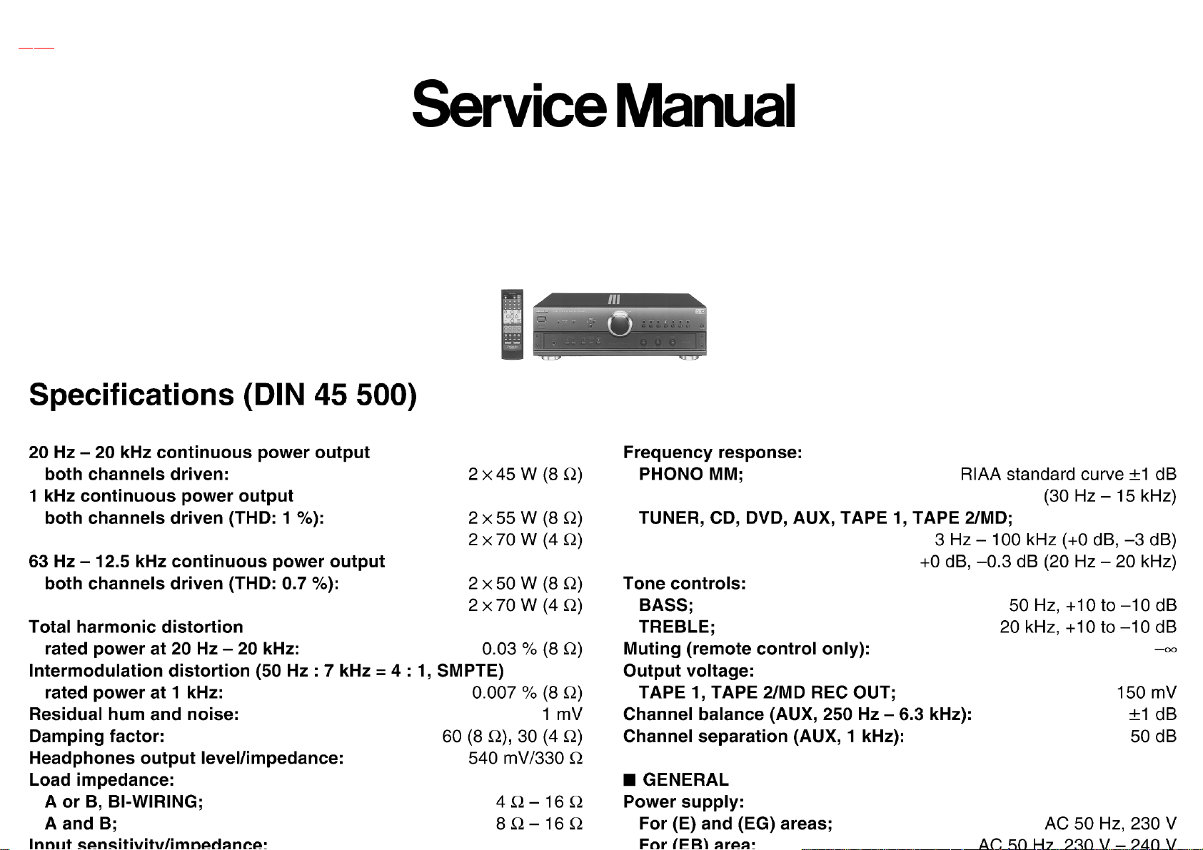
Stereo Integrated Amplifier
SU-A707
Colour
(K)...............Black Type
Areas
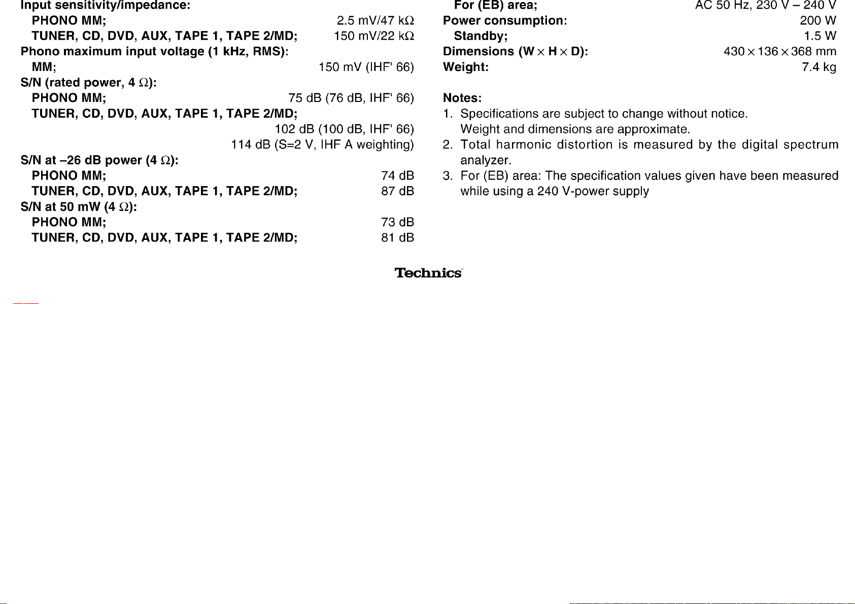
(E)...............Europe and Russia.
(EB)............Great Britain.
(EG)............Germany, France and Italy.
Page 4
© 1999 Matsushita Electric Industrial Co., Ltd. All rights reserved. Unauthorized copying and distribution is a violation of law.
•@
TOP NEXT
Page 5

1 Before Repair
TOP PREVIOUS NEXT
1. Turn off the power supply. Using a 10Ω, 10 W resistor, connect both ends of power supply
capacitors (C701, C702) in order to discharge the voltage.
2. Before turning the power supply on, after completion of repair, slowly apply the primary
voltage by using a power supply voltage controller to make sure that the consumed current at
50 Hz in NO SIGNAL mode should be shown below with respectto supply voltage 230/240 V.
•@
TOP PREVIOUS NEXT
Power supply
voltage
Consumed current 70-270 mA 60-260 mA
AC 230 V, 50
Hz
AC 240 V, 50
Hz
Page 6

2 Protection Circuitry
TOP PREVIOUS NEXT
The protection circuitry may have operated if either of the following conditions is noticed:
No sound is heard when the power is switched ON.
Sound stops during a performance.
The functions of this circuitry is to prevent circuitry damage if, for example, the positive and negative
speaker connection wires are shorted, or if speaker systems with an impedance less than the indicated
rated impedance of this unit are used.
If this occurs, follow the procedure outlined bellow:
1. Switch OFF the power.
2. Determine the cause of the problem and correct it.
3. Switch ON the power once again.
Note:
When the protection circuitry functions, the unit will not operate unless the power is first switched
OFF and ON again.
•@
TOP PREVIOUS NEXT
Page 7
3 Accessories
TOP PREVIOUS NEXT
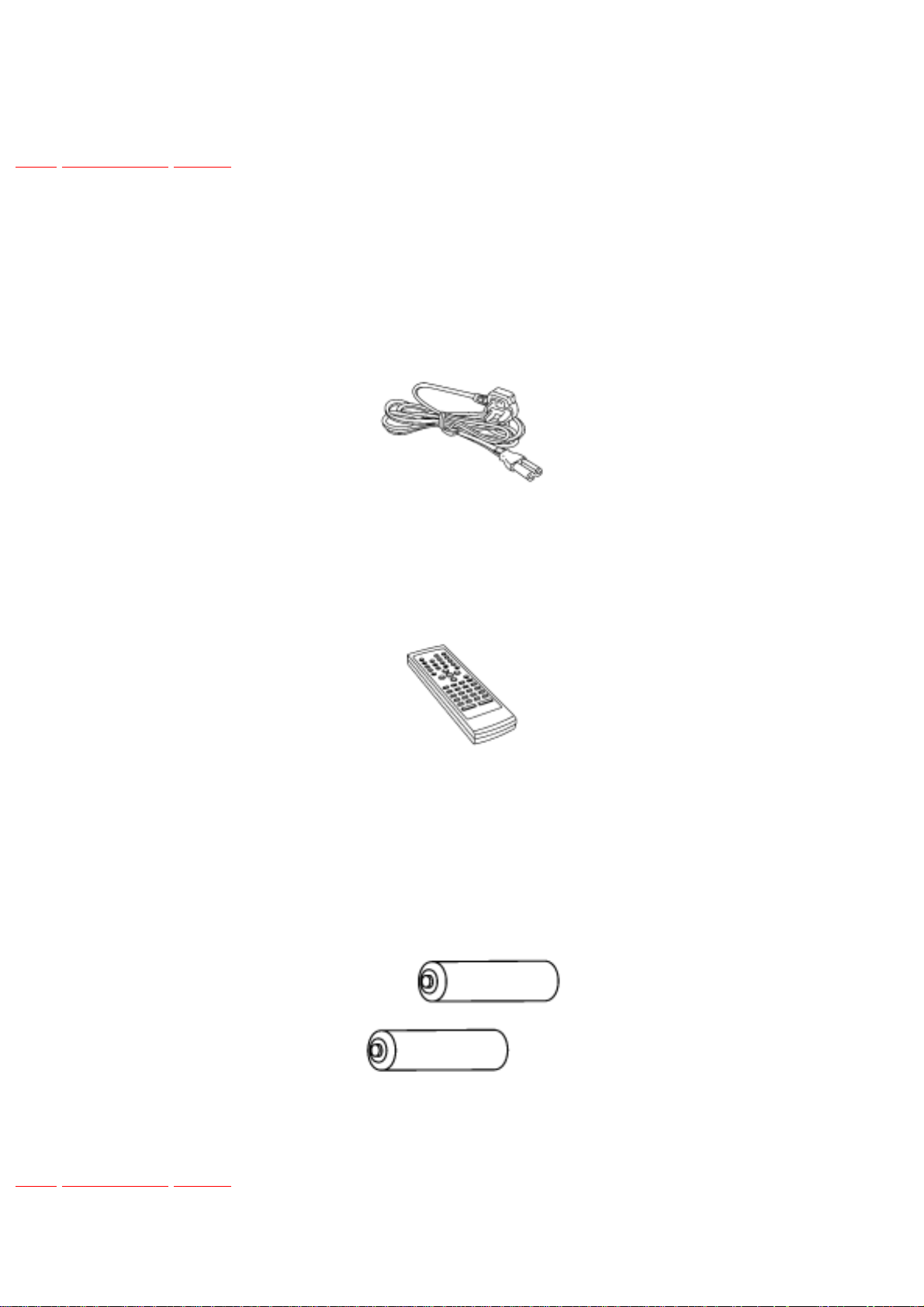
AC mains lead
(E) and (EG) areas : (RJA0019-X)......... 1 pc.
(EB) area : (RJA0053-2X)........................1 pc.
Remote control transmitter
(RAK-SUA11WH).............................................1 pc.
Batteries
(R6/LR6, AA, UM-3).............................................2 pcs.
Note: These are available on sales route.
•@
TOP PREVIOUS NEXT
Page 8
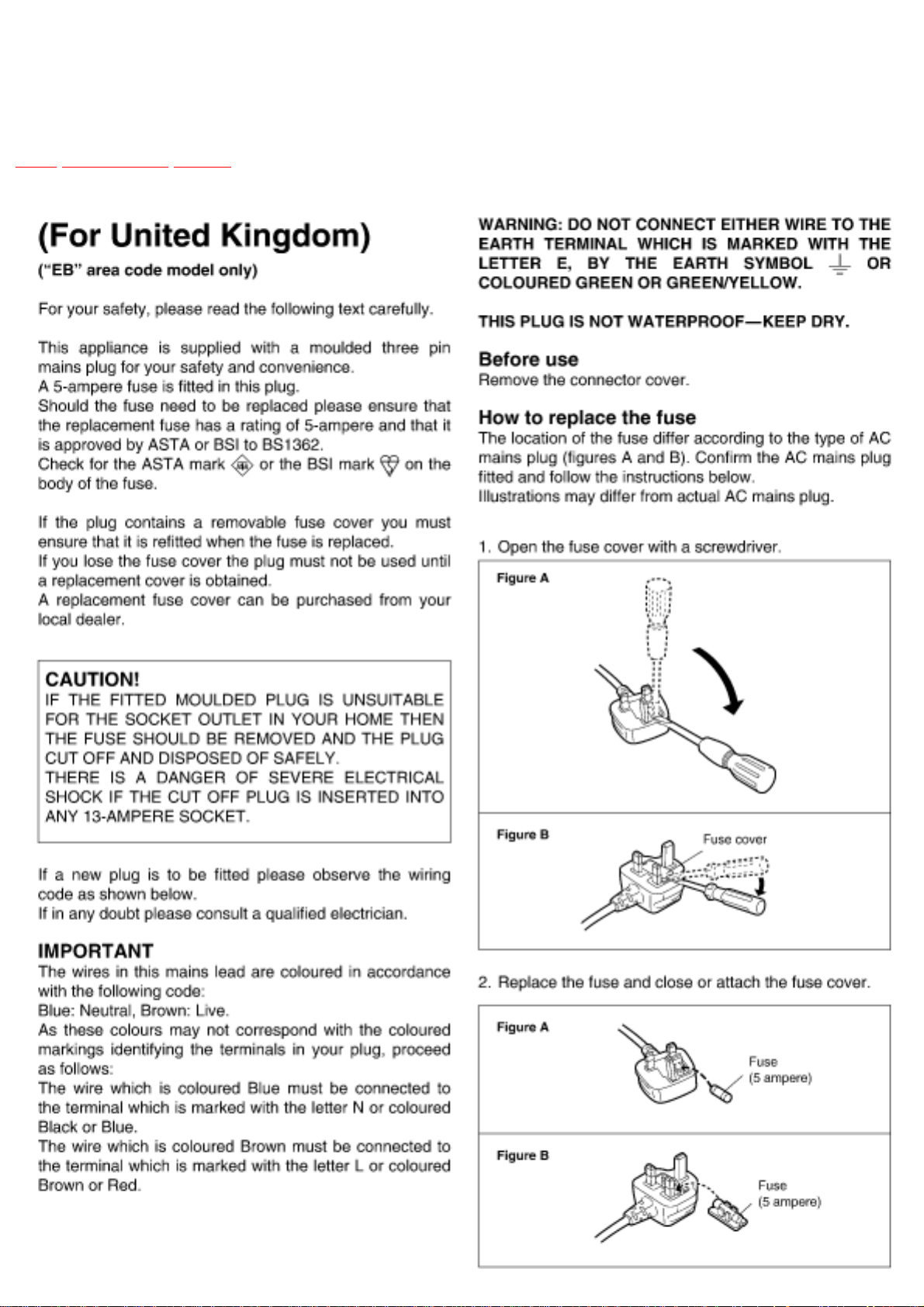
4 Caution for AC Mains Lead
TOP PREVIOUS NEXT
Page 9

5 Operations
TOP PREVIOUS NEXT
•@
TOP PREVIOUS NEXT
Page 10
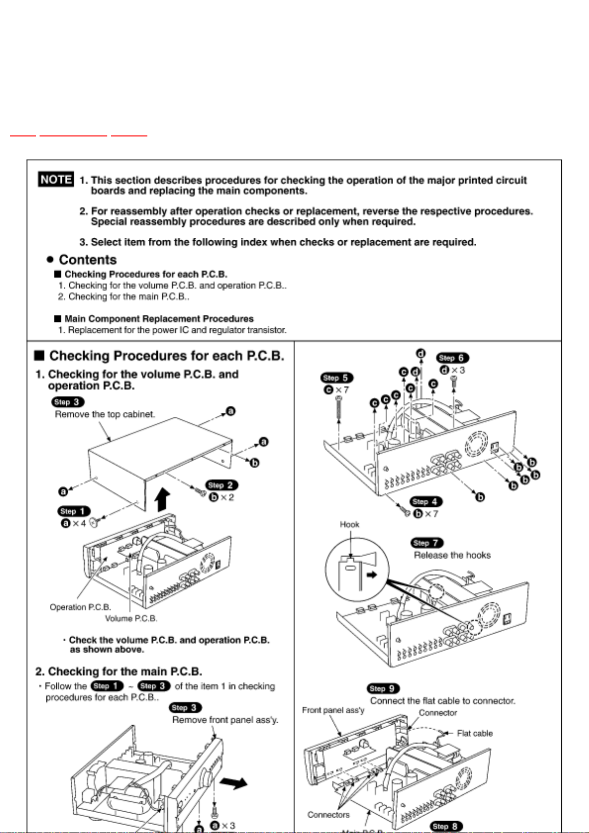
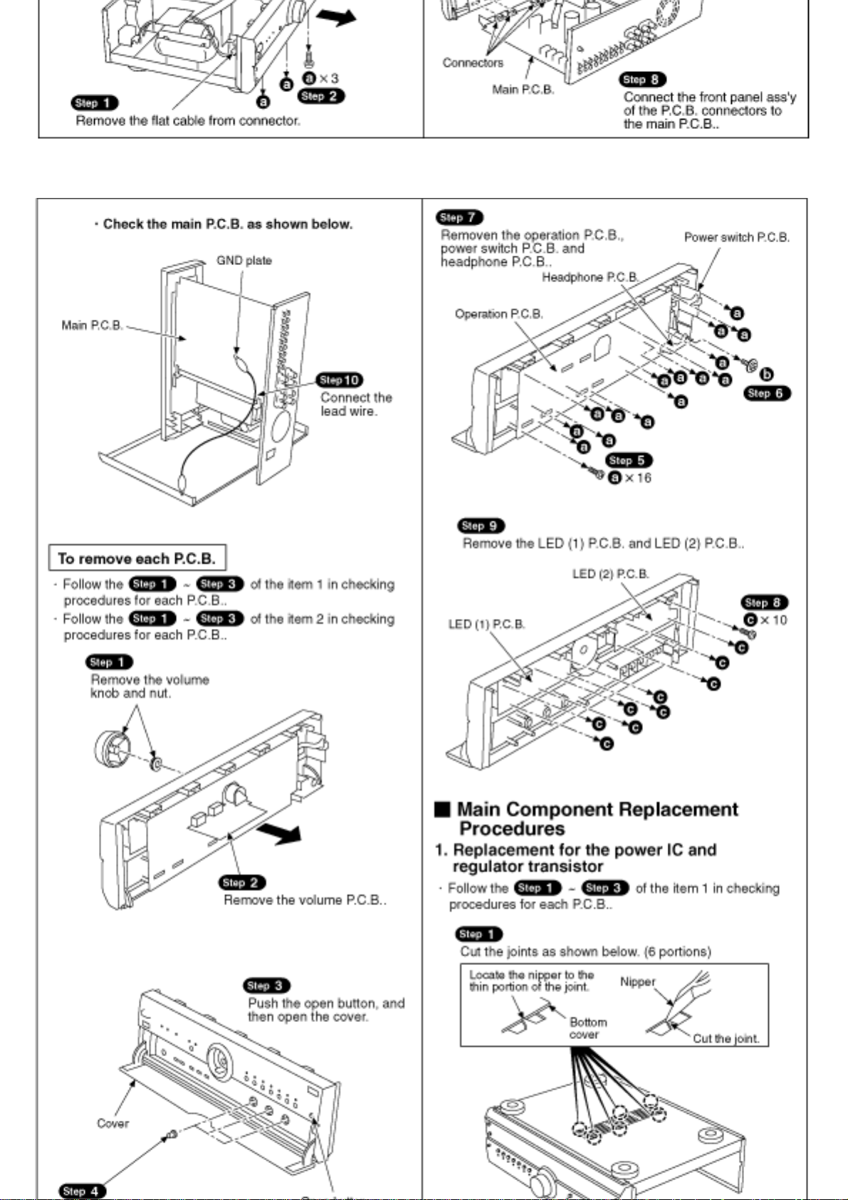
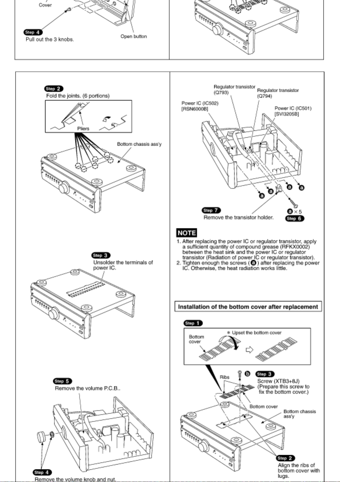
6 Operation Checks and Component
Replacement/Procedures
TOP PREVIOUS NEXT
Page 11
Page 12
Page 13

•@
TOP PREVIOUS NEXT
Page 14

7 About the+/- 15 V Line Abnormality Detect
Function
TOP PREVIOUS NEXT
1. This model features the function that shuts down the main power source when it check the± 15
V line with the IC801 (microcomputer) and find the different voltage. (After power is turned
on, the unit enters the stand-by mode.)
2. When the unit enters stand-by mode with abnormality detected, check the circuits around the±
15 V line. (Specially check the abnormality of the stabilizing power source circuit.)
3. To clear this stand-by mode, short-circuit the TP801 land on the circuit board. However,
clearance of the stand-by mode and turn on the electricity when the repair is not completed
may lead to another trouble. Therefore, be especially carefulto do so. (Do not turn on the
electricity for a long time.)
4. When the repair is completed, leave the TP801 open.
7.1 About the abnormality detect function with the operation LED turned off
•@
TOP PREVIOUS NEXT
Page 15

7.1 About the abnormality detect function with
the operation LED turned off
TOP PREVIOUS NEXT
1. If the operation LED is turned off, there are possibilities of the following abnormalities in
addition to the LED itself malfunctioning:
2. Power amplifier´s malfunction by the speaker terminal short-circuit.
3. Malfunction of cooling fan.
The unit features the function that detects above abnormalities.
•@
TOP PREVIOUS NEXT
Page 16

8 Schematic Diagram
TOP PREVIOUS NEXT
8.1 Schematic Diagram Notes
8.2 Schematic Diagram
•@
TOP PREVIOUS NEXT
Page 17

8.1 Schematic Diagram Notes
TOP PREVIOUS NEXT
This schematic diagram may be modified at any time with the development of new technology.
Notes:
S204:
Unit on/off switch (/I)
S801:
Input select switch (TAPE 1)
S802:
Input select switch (TAPE 2/MD)
S803:
Input select switch (AUX)
S804:
Input select switch (DVD)
S805:
Input select switch (CD)
S806:
Input select switch (TUNER)
S807:
Input select switch (PHONO)
S808:
Page 18

VGCA switch ()
S809:
Tape monitor (SOURCE) switch (TAPE MONITOR)
S810:
Tape monitor (TAPE 2/MD) switch (TAPE MONITOR)
S811:
Tape monitor (TAPE 1) switch (TAPE MONITOR)
S812:
Speaker select switch (SPEAKER B)
S813:
Speaker select switch (SPEAKER A)
VR201:
Volume control VR (VOLUME)
VR202:
Balance control VR (BALANCE)
VR203:
Output voltage adjustment VR (L ch)
VR204:
Output voltage adjustment VR (R ch)
VR301:
Tone control VR (BASS)
VR302:
Page 19

Tone control VR (TREBLE)
Indicated voltage values are the standard values for the unit measured by the DC electronic circuit
tester (high-impedance) with the chassis taken as standard. Therefore, there may exist some errors in
the voltage values, depending on theinternal impedance of the DC circuit tester.
No mark : Power ON
Important safety notice:
Components identified by
Furthermore, special parts which have purposes of fire-retardant (resistors), high-quality sound
(capacitors), low-noise (resistors), etc. are used.
When replacing any of components, be sure to use only manufacturers specified parts shown in the
parts list.
Caution!
IC and LSI are sensitive to static electricity.
Secondary trouble can be prevented by taking care during repair.
Cover the parts boxes made of plastics with aluminum foil.
Ground the soldering iron.
mark have special characteristics important for safety.
Put a conductive mat on the work table.
Do not touch the legs of IC or LSI with the fingers directly.
Voltage and signal line
: Positive voltage line
: Negative voltage line
: Phono signal line
: Tape rec signal line
•@
Page 20

8.2 Schematic Diagram
TOP PREVIOUS NEXT
•@
TOP PREVIOUS NEXT
Page 21

9 Printed Circuit Board Diagram
TOP PREVIOUS NEXT
•@
TOP PREVIOUS NEXT
Page 22

10 Wiring Connection Diagram
TOP PREVIOUS NEXT
•@
TOP PREVIOUS NEXT
Page 23

11 Type Illustration of ICs, Transistors and
Diodes
TOP PREVIOUS NEXT
•@
TOP PREVIOUS NEXT
Page 24

12 Block Diagram
TOP PREVIOUS NEXT
•@
TOP PREVIOUS NEXT
Page 25

13 Measurements and Adjustments
TOP PREVIOUS NEXT
13.1 Measuring Instruments and Special Tools
13.2 Output Voltage Adjustment
•@
TOP PREVIOUS NEXT
Page 26

13.1 Measuring Instruments and Special Tools
TOP PREVIOUS NEXT
AC electronic voltmeter (AC EVM)
AF oscillator
•@
TOP PREVIOUS NEXT
Page 27

13.2 Output Voltage Adjustment
TOP PREVIOUS NEXT
1. Turn on the power.
2. Select the input source to TUNER.
3. Connect the measuring instrument as shown
4. Apply 1 kHz, 100 mV to TUNER terminal.
5. Adjust the VOLUME to maximum.
6. Adjust VR203 (L ch) and VR204 (R ch) so that the output voltage to AC 14.0± 0.2 V. Shown in
Fig.1
Fig.1
Fig.2
Adjustment point
Fig.2
Page 28

•@
TOP PREVIOUS NEXT
Page 29

14 Terminal Function of ICs
TOP PREVIOUS NEXT
14.1 IC801 (M38503M2405F) : System Control
•@
TOP PREVIOUS NEXT
Page 30

14.1 IC801 (M38503M2405F) : System Control
TOP PREVIOUS NEXT
Pin
No.
1
2 VREF I Reference voltage input
3 AGND - GND terminal
4 MUTE LED O LED drive signal output (Mute)
5 STBY LED O LED drive signal output (Stand by)
6 REMCON I Remote control signal input
7 BACKUP I Power failure detect signal input
8 NC - Not used, connected to GND
9 SEL DATA O Data signal output for input select IC (IC201)
10 SEL CLK O
Name
VCC
I/
O
Power supply terminal
I
Clock signal output for input select IC
(IC201)
Function
11 SEL STB O
12 POWER SW I Power switch (S204) detect signal input
13 LED O - Not used, open
14 LED C O Input select LED drive signal output
15
16 LED B O Input select LED drive signal output
17 LED A O Input select LED drive signal output
18 RESET I System reset signal input
19 X IN I Connected to the ceramic oscillator (8 MHz)
20 X OUT O Connected to the ceramic oscillator (8 MHz)
21 GND - GND terminal
22 TAPE2 LED O LED drive signal output (Tape 2)
CNVSS
Strobe signal output for input select IC
(IC201)
Connected to GND
-
23 TAPE1 LED O LED drive signal output (Tape 1)
24
SOURCE
LED
O LED drive signal output (Source)
Page 31

25 SP B LED O LED drive signal output (Speaker B)
26 SP A LED O LED drive signal output (Speaker A)
27 VRDOWN O Motor drive signal output (Volume down)
28 VRUP O Motor drive signal output (Volume up)
29 S MUTE O Audio muting control signal output
30 POWER O Power relay control signal output
31 SP B RLY O Speaker B relay control signal output
32 SP A RLY O Speaker A relay control signal output
33 VGCA RLY O VGCA mode relay control signal output
34 TAPE1 RLY O Tape 1 relay control signal output
35 DVD RLY O DVD relay control signal output
36 CD RLY O CD relay control signal output
37 MON RLY O Monitor relay control signal output
38 VGCA LED O LED drive signal output (VGCA mode)
39 VIA LED O LED drive signal output (VIA mode)
40 REG MON I Regulation monitor signal input
41 KEY AD2 I Operation key signal input
42 KEY AD1 I Operation key signal input
•@
TOP PREVIOUS NEXT
Page 32

15 Replacement Parts List
TOP PREVIOUS NEXT
Notes:
Important safety notice:
Components identified by
Furthermore, special parts which have purposes of fire-retardant (resistors), high-quality sound
(capacitors), low-noise (resistors), etc. are used.
When replacing any of components, be sure to use only manufactures specified parts shown in the
parts list.
The<IA> <IB> <IC> <ID> marks in Remarks indicate language of instruction manual.
<IA> : English, Spanish, Swedish, Russian, Polish, Czech
<IB> : English
<IC> : German, Italian, French
<ID> : Netherlandish, Danish
mark have special characteristics important for safety.
The parenthesized indications in the Remarks columns specify the areas. (Refer to the cover page for
area.)
The marking (RTL) indicates that Retention Time is Limited for this item. After the discontinuation
of this assembly in production, the item will continue to be available for a specific period of time.
The retention period of availabilityis dependent on the type of assembly, and in accordance with the
laws governing part and product retention. After the end of this period, the assembly will no longer
be available.
All parts are supplied by MESA.
Ref. No. Part No. Part Name& Description Pcs. Remarks
1 RKM0219F-K TOP CABINET 1
2 RHD30035-K1 SCREW 4
Page 33

3 RMR1110-K SP TERMINAL COVER 8 (EB)
4 XTBS3+8JFZ1 SCREW 2
5 RDG0438 GEAR 1
6 REM0072-3 FAN 1
7 RHD30070 SCREW 1
8 XTB3+6G SCREW 4
9 XTB3+6JFZ SCREW 4
10 RKA0053-A FOOT 4
10-1 RMG0270-K RUBBER 4
11 RMG0332-K RUBBER 2
12 XTB3+8JFZ SCREW 2
13 RGK1111-K NUT 4
14 RHD26033 SCREW 4
15 RKF0596-Q DOOR 1
16 RMR1252-K ARM(L) 1
17 RMR1253-K ARM(R) 1
18 RGB0031-A TECHNICS BADGE 1
19 RGB0112-N VGCA BADGE 1
20 RGH0155B-K PANEL SHEET 1
21 RGK1182-N BUTTON ORNAMENT 1
22 RGK1184-S VOLUME RING 1
23 RGL0453-Q PANEL LIGHT 1 1
24 RGL0456-Q PANEL LIGHT 2 1
25 RGL0457-Q PANEL LIGHT 3 1
26 RGP0746B-K PANEL 1
27 RGU0890-1K BUTTON,POWER 1
28 RGU1712-K BUTTON,OPEN 1
29 RGU1782-K BUTTON,SELECTOR 1
30 RGU1784-S BUTTON,SPEAKER 1
31 RGW0285-S KNOB,TONE 3
32 RGW0325-K KNOB,VOLUME 1
33 RHD26016 SCREW 2
34 RHD26034 SCREW 1
35 RHN90001 NUT 1
Page 34

36 RKG0009 MAGNET 1
37 RKW0273A-K FILTER 1
38 RME0284 SPRING 1
39 RMR1254-K LEVER 1
40 RMR1261-K HOLDER 1
41 XTBS26+8J SCREW 26
42 XTBS3+8JFZ1 SCREW 22
43 XTW3+15T SCREW 5
44 XTB3+20JFZ SCREW 8
A1 RAK-SUA11WH REMOTE CONT.TRANSMITTER 1
A1-1 RKK0123-K BATTERY COVER 1
A2 RJA0019-X AC POWER SUPPLY CORD 1 (E,EG)/
A2 RJA0053-2X AC POWER SUPPLY CORD 1 (EB)/
A3 RQA0117 WARRANTY CARD 1
A4 RQCB0169 SERVICE CENTER LIST 1
A5 RQT5113-E OPERATING INSTRUCTIONS 1 (E)/<IA>
A6 RQT5116-B OPERATING INSTRUCTIONS 1 (EB)/<IB>
A7 RQT5114-D OPERATING INSTRUCTIONS 1 (EG)/<IC>
A8 RQT5115-H OPERATING INSTRUCTIONS 1 (EG)/<ID>
C103,04 ECBT1H181KB5 50V 180P 2
C107,08 ECEA1CKS101 16V 100U 2
C109,10 ECBT1H391KB5 50V 390P 2
C113,14 ECQB1H223JF3 50V 0.022U 2
C115,16 ECQB1H562JF3 50V 5600P 2
C117,18 RCE1HKA4R7BG 50V 4.7U 2
C119,20 ECQB1H472JF3 50V 4700P 2
C121,22 ECBT1E103ZF 25V 0.01U 2
C123,24 RCE1HKA3R3BG 50V 3.3U 2
C201-16 ECCR1H101K5 50V 100P 16
C251,52 ECEA0JKS101 6.3V 100U 2
C253,54 ECQV1H104JM3 50V 0.1U 2
C301,02 RCE1HKA3R3BG 50V 3.3U 2
C303,04 ECCR1H101K5 50V 100P 2
C305,06 ECBT1H820KB5 50V 82P 2
Page 35

C307,08 RCE1HKA4R7BG 50V 4.7U 2
C309,10 ECBT1H390J5 50V 39P 2
C311,12 RCE1CKA100BG 16V 10U 2
C313,14 ECQV1H823JZ 50V 0.082U 2
C315,16 ECQB1H153JF3 50V 0.015U 2
C317,18 ECQB1H183JF3 50V 0.018U 2
C319,20 ECQB1H222JF 50V 2200P 2
C321,22 ECBT1E223ZF 25V 0.022U 2
C323,24 ECBT1H121KB5 50V 120P 2
C351,52 ECA1EPXS100B 25V 10U 2
C353,54 ECBT1H101KB5 50V 100P 2
C355,56 ECA1APXS470B 10V 47U 2
C357,58 ECBT1H820KB5 50V 82P 2
C359,60 ECBT1H180J5 50V 18P 2
C361-64 ECA1EPXS100B 25V 10U 4
C367,68 ECA1CPXS330B 16V 33U 2
C369,70 ECA1EPXS100B 25V 10U 2
C401,02 ECA1CPXS470B 16V 47U 2
C403,04 ECKR1H121KB5 50V 120P 2
C405,06 ECA1APXS101B 10V 100U 2
C407,08 ECBT1H820KB5 50V 82P 2
C409,10 ECCR2H330J5 500V 33P 2
C413,14 ECCV2H070D 500V 7P 2
C415,16 ECBT1H102KB5 50V 1000P 2
C426 ECBT1H102KB5 50V 1000P 1
C427 ECBT1E223ZF 25V 0.022U 1
C428 ECKR1H103ZF5 50V 0.01U 1
C451,52 ECKR1H333ZF5 50V 0.033U 2
C453-56 ECCV2H680K 500V 68P 4
C457-60 RCE1HKA3R3BG 50V 3.3U 4
C461,62 ECBA1H681KB5 50V 680P 2
C501-04 ECA1APXS101B 10V 100U 4
C505,06 ECQV1H473JM3 50V 0.047U 2
C507 ECEA1CKS101 16V 100U 1
C508 ECA1HM470 50V 47U 1
C509 ECEA1HN100SB 50V 10U 1
C511,12 ECBT1H680J5 50V 68P 2
Page 36

C513-18 ECQV1H473JM3 50V 0.047U 6
C519-22 ECQB1H223JF3 50V 0.022U 4
C523,24 ECBT1H102KB5 50V 1000P 2
C525,26 ECQB1H152JF3 50V 1500P 2
C531,32 ECBT1C332KR5 16V 3300P 2
C601,02 RCE1CKA100BG 16V 10U 2
C603 ECEA0JKS101 6.3V 100U 1
C604 ECEA1HSN010 50V 1U 1
C605 ECEA0JKS331 6.3V 330U 1
C701,02 ECESX1H822UM 50V 8200U 2
C705 ECBT1H104KB5 50V 0.1U 1
C707,08 ECA1HPXS100B 50V 10U 2
C709,10 ECKR2H103ZU 500V 0.01U 2
C711 ECQE2104KF3 250V 0.1U 1
C712 ECBT1E103ZF 25V 0.01U 1
C714 ECA1CM471 16V 470U 1
C715 ECBT1E103ZF 25V 0.01U 1
C716 RCE1CM102BV 16V 1000U 1
C751,52 ECA1EPXS470B 25V 47U 2
C787,88 ECKR1H103ZF5 50V 0.01U 2
C793,94 ECEA1EKA470B 25V 47U 2
C801-03 ECBT1E103ZF 25V 0.01U 3
C804 ECA0JM102 6.3V 1000U 1
C805 RCE1HKAR47BG 50V 0.47U 1
C806 ECEA1HKS2R2 50V 2.2U 1
C807 ECBT1H102KB5 50V 1000P 1
C808 ECBT1E103ZF 25V 0.01U 1
C809,10 RCE1AKA470BG 10V 47U 2
C811 ECBT1H101KB5 50V 100P 1
C812,13 ECKR1H103ZF5 50V 0.01U 2
C814,15 ECA1CPXS100B 16V 10U 2
C816 RCE1CKA100BG 16V 10U 1
C817 RCE1AKA470BG 10V 47U 1
C820 ECQV1H224JM3 50V 0.22U 1
CN201 RJU003K010M1 CONNECTOR(10P) 1
CN202 RJU003K008M1 CONNECTOR(8P) 1
Page 37

CN301 ,02 RJU003K008M1 CONNECTOR(8P) 2
CN401 RJU057W004 CONNECTOR(4P) 1
CN601 SJT3213 CONNECTOR(2P) 1
CN702 RJS1A6607T1 CONNECTOR(7P) 1
CN703 RJS1A6603 CONNECTOR(3P) 1
CN704-11 RJS1A1101T1 CONNECTOR(1P) 8
CN801, 02 RJU003K008M1 CONNECTOR(8P) 2
CN803 RJU071H11M CONNECTOR(11P) 1
CN805 RJU071H11M CONNECTOR(11P) 1
CP201 RJT003K010-1 CONNECTOR(10P) 1
CP202 RJT003K008-1 CONNECTOR(8P) 1
CP301 ,02 RJT003K008-1 CONNECTOR(8P) 2
CP401 RJT057W004-1 CONNECTOR(4P) 1
CP801 ,02 RJT003K008-1 CONNECTOR(8P) 2
CP803 RJT071K11 CONNECTOR(11P) 1
CP805 RJT071K11 CONNECTOR(11P) 1
D351 MA165 DIODE 1
D401,02 MA167 DIODE 2
D403,04 MA4036M DIODE 2
D405,06 MA165 DIODE 2
D451 MA165 DIODE 1
D452 MA4056M DIODE 1
D453 MA29WA DIODE 1
D501,02 MA165 DIODE 2
D503,04 MA4160M DIODE 2
D505 MA165 DIODE 1
D506 1SS291TA DIODE 1
D507 MA165 DIODE 1
D605 MA4091M DIODE 1
D606 MA165 DIODE 1
D608-10 MA165 DIODE 3
D611,12 MA167 DIODE 2
D613 MA700 DIODE 1
D701-04 P300DLF DIODE 4
D705 1SR35200TB DIODE 1
Page 38

D706 MA165 DIODE 1
D709 MA4056-LTA DIODE 1
D710-13 1SR35200TB DIODE 4
D795,96 MA4160M DIODE 2
D801 MA4068L DIODE 1
D802 1SS291TA DIODE 1
D803-07 MA165 DIODE 5
D808 1SS291TA DIODE 1
D809,10 MA165 DIODE 2
D825-28 MA165 DIODE 4
D829 MA700 DIODE 1
D851-57 SLR325VCT31 LED 7
D858 SLR325DCT31 LED 1
D859-65 SLR325VCT31 LED 7
D866,67 SLR325DCT31 LED 2
F1 XBA2C20TB0 FUSE 1
IC101 AN6558F IC 1
IC201 NJU7312AL IC 1
IC251 BA6218 IC 1
IC301 UPC4570C IC 1
IC351,52 NJM4580DD IC 2
IC401 AN7062N IC 1
IC501 SVI3205B IC 1
IC502 RSN6000B IC 1
IC601 M5218AP IC 1
IC801 M38503M2405F IC 1
IC803 TC74HC42AP IC 1
JK1 SJS9236 JACK,AC INLET 1
JK201-04 SJF3069N JACK,IN/OUT 4
JK205 SJF3068-7N JACK,TAPE1 PLAY(IN) 1
JK501 RJH4801M-1 JACK,SPEAKERS 1 (E,EG)
JK501 RJH4801M-2 JACK,SPEAKERS 1 (EB)
JK502 RJJ63TA01 JACK,PHONES 1
Page 39

L1 RLQZ271M COIL,CHOKE 1
L201-04 ELEXT470KA9 COIL 4
L251,52 ELEXT1R0KA9 COIL 2
L501-04 SLQY18G-10 COIL,CHOKE 4
L801 ELEXT101KA9 COIL 1
P1 RPQ0164 PAD 1
P2 RPF0139 PROTECTION COVER 1
P3 RPG4559 PACKING CASE 1 (E)
P3 RPG4560 PACKING CASE 1 (EB,EG)
P4 RPN1221 PAD 1
P5 RPH0032 MIRROR SHEET 1 (EB)
P6 SPP730 SHEET 1
PCB1 REP2865D-M MAIN PCB 1 (E,EG)/(RTL)
PCB1 REP2865E-M MAIN PCB 1 (EB)/(RTL)
PCB2 REP2866D-S SUB PCB 1 (E,EG)/(RTL)
PCB2 REP2866E-S SUB PCB 1 (EB)/(RTL)
Q401,02 2SA992F TRANSISTOR 2
Q451,52 2SC1845F TRANSISTOR 2
Q453,54 2SC3311AR TRANSISTOR 2
Q455,56 2SA1309AR TRANSISTOR 2
Q501-03 2SA992F TRANSISTOR 3
Q601 2SD893AR TRANSISTOR 1
Q602-04 2SA1048GR TRANSISTOR 3
Q605,06 2SC3311AR TRANSISTOR 2
Q607 UN4113 TRANSISTOR 1
Q608 UN4213 TRANSISTOR 1
Q701 2SB621A-R TRANSISTOR 1
Q793 2SD2374PQAU TRANSISTOR 1
Q794 2SB1548PQAU TRANSISTOR 1
Q801 UN4211 TRANSISTOR 1
Q802 UN4111 TRANSISTOR 1
Q803 UN4211 TRANSISTOR 1
Q804 UN4111 TRANSISTOR 1
Page 40

Q805 UN4211 TRANSISTOR 1
Q806 UN4111 TRANSISTOR 1
Q807 UN4211 TRANSISTOR 1
Q808-10 UN4111 TRANSISTOR 3
Q811 UN4211 TRANSISTOR 1
Q812 UN4111 TRANSISTOR 1
Q813-18 UN4211 TRANSISTOR 6
Q819 2SD2037DEFTA TRANSISTOR 1
Q820 2SK2880BCTA TRANSISTOR 1
Q824,25 2SK301QRS TRANSISTOR 2
Q826 2SA1048GR TRANSISTOR 1
R101,02 ERDS2FJ152 1/4W 1.5K 2
R105,06 ERDS2FJ224 1/4W 220K 2
R109,10 ERDS2FJ101 1/4W 100 2
R113,14 ERDS2FJ563 1/4W 56K 2
R117,18 ERDS2FJ271 1/4W 270 2
R123,24 ERDS2FJ680 1/4W 68 2
R125,26 ERDS2FJ184 1/4W 180K 2
R127,28 ERDS2FJ123 1/4W 12K 2
R129,30 ERDS2FJ563 1/4W 56K 2
R131,32 ERDS2FJ102 1/4W 1K 2
R201,02 ERDS2FJ102 1/4W 1K 2
R205-16 ERDS2FJ102 1/4W 1K 12
R217,18 ERDS2FJ334 1/4W 330K 2
R219-21 ERDS2FJ103 1/4W 10K 3
R223,24 ERDS2FJ393 1/4W 39K 2
R251 ERDS1FJ100 1/2W 10 1
R301,02 ERDS2FJ563 1/4W 56K 2
R303,04 ERDS2FJ123 1/4W 12K 2
R305-08 ERDS2FJ224 1/4W 220K 4
R309,10 ERDS2FJ392 1/4W 3.9K 2
R311,12 ERDS2FJ102 1/4W 1K 2
R313,14 ERDS2FJ223 1/4W 22K 2
R315,16 ERDS2FJ392 1/4W 3.9K 2
R317,18 ERDS2FJ183 1/4W 18K 2
R351,52 ERDS2FJ102 1/4W 1K 2
Page 41

R353,54 ERDS2FJ473 1/4W 47K 2
R355,56 ERDS2FJ102 1/4W 1K 2
R357,58 ERDS2FJ224 1/4W 220K 2
R361,62 ERDS2FJ183 1/4W 18K 2
R365,66 ERDPS2VF102T 1/4W 1K 2
R367,68 ERDS2FJ392 1/4W 3.9K 2
R401,02 ERDS2FJ272 1/4W 2.7K 2
R403,04 ERDS2FJ393 1/4W 39K 2
R405,06 ERDS2FJ272 1/4W 2.7K 2
R407,08 ERDS2FJ393 1/4W 39K 2
R411,12 RREKFJ470VM 1/4W 47 2
R437 ERDS2FJ473 1/4W 47K 1
R457 ERDS2FJ153 1/4W 15K 1
R459,60 RREKFJ101VM 1/4W 100 2
R461-64 ERDS2FJ333 1/4W 33K 4
R465-68 RREKFJ101VM 1/4W 100 4
R469 ERDS2FJ103 1/4W 10K 1
R470 ERDS2FJ102 1/4W 1K 1
R471,72 ERDS2FJ561 1/4W 560 2
R501,02 ERDS2FJ362 1/4W 3.6K 2
R503,04 RREKFJ121VM 1/4W 120 2
R505,06 ERDS2FJ392 1/4W 3.9K 2
R507,08 RREKFJ121VM 1/4W 120 2
R513-16 RREKFJ100VM 1/4W 10 4
R517-20 ERDS1FJ6R8 1/2W 6.8 4
R521,22 ERDS1FJ100 1/2W 10 2
R527 ERDS2FJ223 1/4W 22K 1
R528 ERDS2FJ824 1/4W 820K 1
R529 ERDS2FJ124 1/4W 120K 1
R530 ERDS1FJ272 1/2W 2.7K 1
R531,32 ERDS1FJ100 1/2W 10 2
R533,34 ERDS2FJ182 1/4W 1.8K 2
R535 ERDS2FJ562 1/4W 5.6K 1
R536,37 ERDS2FJ103 1/4W 10K 2
R550,51 ERDS2FJ222 1/4W 2.2K 2
R555 ERG1SJ681 1W 680 1
R556 ERG1SJ561 1W 560 1
Page 42

R557 ERG1SJ681 1W 680 1
R558 ERG1SJ561 1W 560 1
R559,60 ERDS1FJ122 1/2W 1.2K 2
R561,62 ERG1SJ151 1W 150 2
R563,64 ERG1SJ181 1W 180 2
R565-70 ERDS2FJ223 1/4W 22K 6
R611-14 ERDS2FJ223 1/4W 22K 4
R615-18 ERDS2FJ103 1/4W 10K 4
R619 ERDS2FJ151 1/4W 150 1
R620 ERDS2FJ153 1/4W 15K 1
R621,22 ERDS2FJ223 1/4W 22K 2
R624 ERDS2FJ333 1/4W 33K 1
R625 ERDS2FJ223 1/4W 22K 1
R626 ERDS2FJ103 1/4W 10K 1
R628 ERDS2FJ564 1/4W 560K 1
R629 ERDS2FJ473 1/4W 47K 1
R630 ERDS2FJ150 1/4W 15 1
R632 ERDS2FJ222 1/4W 2.2K 1
R633 ERDS2FJ563 1/4W 56K 1
R634 ERDS2FJ223 1/4W 22K 1
R637 ERDS2FJ222 1/4W 2.2K 1
R707,08 RREKFJ6R8VM 1/4W 6.8 2
R709,10 RREKFJ470VM 1/4W 47 2
R711 ERDS2FJ221 1/4W 220 1
R712 RREKFJ2R2VM 1/4W 2.2 1
R713 ERDS2FJ223 1/4W 22K 1
R714 ERDS2FJ222 1/4W 2.2K 1
R715 ERDS2FJ221 1/4W 220 1
R793,94 ERDS2FJ103 1/4W 10K 2
R801 ERDS2FJ821 1/4W 820 1
R802 ERDS2FJ102 1/4W 1K 1
R803 ERDS2FJ122 1/4W 1.2K 1
R804 ERDS2FJ152 1/4W 1.5K 1
R805 ERDS2FJ182 1/4W 1.8K 1
R806 ERDS2FJ103 1/4W 10K 1
R807 ERDS2FJ821 1/4W 820 1
R808 ERDS2FJ102 1/4W 1K 1
Page 43

R809 ERDS2FJ122 1/4W 1.2K 1
R810 ERDS2FJ152 1/4W 1.5K 1
R811 ERDS2FJ182 1/4W 1.8K 1
R812 ERDS2FJ222 1/4W 2.2K 1
R813 ERDS2FJ103 1/4W 10K 1
R814 ERDS2FJ1R0 1/4W 1 1
R815 ERDS2FJ104 1/4W 100K 1
R816-18 ERDS2FJ102 1/4W 1K 3
R819 ERDS2FJ104 1/4W 100K 1
R820 ERDS2FJ102 1/4W 1K 1
R821,22 ERDS2FJ103 1/4W 10K 2
R823 ERDS2FJ102 1/4W 1K 1
R824 ERDS2FJ472 1/4W 4.7K 1
R825-27 ERDS2FJ104 1/4W 100K 3
R828 ERDS2FJ102 1/4W 1K 1
R829 ERDS2FJ103 1/4W 10K 1
R830 ERDS2FJ223 1/4W 22K 1
R831 ERDS2FJ333 1/4W 33K 1
R832,33 ERDS2FJ104 1/4W 100K 2
R834 ERD2FCJ4R7 1/4W 4.7 1
R835 ERDS2FJ105 1/4W 1M 1
R845 ERDS2FJ334 1/4W 330K 1
R851 ERDS2FJ331 1/4W 330 1
R852 ERDS2FJ271 1/4W 270 1
R853,54 ERDS2FJ331 1/4W 330 2
R855 ERDS2FJ271 1/4W 270 1
R857-61 ERDS2FJ331 1/4W 330 5
R862 ERDS1FJ471 1/2W 470 1
RL201-04 RSY0020M-R RELAY 4
RL351 RSY0020M-R RELAY 1
RL501 ,02 RSY0013M-0 RELAY 2
RL503 RSY0020M-R RELAY 1
RL701 ,02 RSY0019M-0 RELAY 2
S204 RSP2B023-A SW,UNIT ON/OFF 1
S801-13 EVQ21405R SW,PUSH 13
Page 44

•@
T1 RTP7K5E009AW POWER TRANSFORMER 1 (E,EG)/
T1 RTP7K5B005AW POWER TRANSFORMER 1 (EB)/
TH201 ,02 ERTD2ZHL104T THERMISTOR 2
VR201 EUWMRUF25461 VR,VOLUME 1
VR202 EVJ02SFA5G15 VR,BALANCE 1
VR203 ,04 EVNDXAA00B23 VR,OUTPUT VOL.ADJ. 2
VR301 ,02 EVJYA1FA5C15 VR,BASS/TREBLE 2
X801 RSXY8M00D01T OSCILLATOR 1
Z801 RCDGP1U27XD REMOTE SENSOR 1
TOP PREVIOUS NEXT
Page 45

16 Cabinet Parts Location
TOP PREVIOUS NEXT
•@
TOP PREVIOUS NEXT
Page 46

17 Packaging
TOP PREVIOUS
•@
TOP PREVIOUS
Page 47

Page 48

Page 49

Page 50

Page 51

Page 52

Page 53

PHONO
TUNER
PLAY(IN)
TAPE2/MD
REC(OUT)
TAPE1
REC(OUT)
AUX
PLAY(IN)
Q807,808
+B1
AN6558F
IC101
Phono
EQ amp.
RL201
Relay
drive
NJU7312AL
SIGNAL SELECTOR
7
(22)
6
(23)
8
(21)
2
(27)
3
(26)
4
(25)
10
(19)
11
(18)
CD
Q803,804
+B1
IC201
X5
X4
X6
X1
X2
X3
X7
X8
Mode
select
Relay
drive
Vss
VDD
GND
RL203
(20)
(24)
14
(17)
9
1
-B1
RL204
28
+B4
5
Q801,802
+B1
Relay
drive
12
13
15
16
NJM4580DD
IC351
Buffer
amp.
VR203(VR204)
(OUTPUT
VOLTAGE
ADJ.)
+B5
VR201
(VOLUME)
M
79
Drive
6
Pre amp
Logic
NJM4580DD
IC352
Buffer
amp.
(BALANCE)
BA6218
IC251
MOTORDRIVE
2,5,8
VR202
31
DVD
RL202
Q805,806
Relay
+B1
drive
+B4 -B1
42
REG MON
SP A LED
26
D863
(SP.A)
+B3
D864
(SP.B)
KEY SWITCH
(S808~813)
41
KEY AD242KEY AD1
SP B LED
25
D865
(SOURCE)
+B3
TAPE
RELAY
24
SOURCE
LED
(TAPE1)
+B3
X801
(8MHz)
2019
XIN
23
D866
+B3 +B3
X OUT
TAPE1 LED
D867
(TAPE2/MD)
CD
RELAY
RESET
Reset Q818
18
RESET
TAPE2 LED
22
10
9
SEL CLK
SEL DATA
M38503M2405F
IC801
SYSTEM CONTROL
LEDB
LED A
16
17
15
14
A
B
TC74HC42AP
IC803
LED DRIVE
Y1~Y7
16
2~7,
9
+B3
CD
DVD
TAPE
RELAY
RELAY
RELAY
11
34
36
35
RLY
TAPE1
CD RLY
SEL STB
LED C
14
REMCON
6
13
C
8
D851~857
(PHONO/TUNER/CD/
DVD/AUX/TAPE1/
/TAPE2&MD)
DVD
RELAY
MONITOR
27
37
DVD RLY
MON RLY
CNVss
3
15
+B3
Z801
(REMOTE
SENSOR)
MONITOR
RELAY
VR DOWN
28
RELAY
VR UP
SP ARLY
VGCA RLY
33
32
VRUP
VRDOWN
AGND
21
GND
SP ARLY
VGCA RLY
STBY LED
5
Q815
LED
drive
D861
()
+B3
31
SP BRLY
SP BRLY
Q816
30
4
LED
drive
+B3
POWER
VR UP
S MUTE
29
7
POWER
S MUTE
MUTE LED
Q813
D860
(MUTING)
VR DOWN
POWER
BUCKUP
12
BACKUP
VGCA LED
38
LED
drive
(VGCA ON)
+B3
SW
POWER
SW
D859
+B3
2
Q814
VREF
39
LED
drive
+B3
+B6
1
Vcc
VIA LED
D858
(VIA TONE)
+B3
Page 54

UPC4570C
IC301
Tone
amp.
treble
bass
VR301(BASS),
VR302(TREBLE)
RL351
Q811,812
+B2
Relay
drive
Q824
(Q825)
Q826
Muting
Muting
cont.
D405(D406)
14
(5)13(6)15(4)12(7)
Current
mirror
17
(2)
6(3)
NF
15(13)
Cascade
Current
stabilizer
11018
(12)
6
Bias Muting
–B1
SVI3205B
IC501
POWER AMP
NF
Bias
AN7062N
IC401
VOLTAGE AMP
–B2
7
11
(8)
9
Q401
(Q402)
Pre
amp.
+B8
Q451
(Q452)
Current
stabilizer
–B2
3
(6)
Notes
Signal line : PHONO signal
Signal line : TAPE REC signal
( ) indicates pin No.Right channel.
RSN6000B
(
)
1/2
IC502
Q453(Q454)
V-AMP/
CLASS AA
AMP
+B8
V-AMP/
CLASS AA
AMP
Q455(Q456)
RSN6000B
(
1/2
IC502
)
Motor
cont/drive
Motor
drive
FAN MOTOR
Q601~608
Rch
M5218AP
IC601
M
HEADPHONES
A
+B5
+B6
+B3
+B1
+B2
+B7
+B8
+B4
-B2
-B1
D808
VGCA RLY
D807
D802
D803
Q793
Regulator
Q794
Regulator
Q820
S MUTE
Q819
Regulator
Stabilizer
RL351
Q503
SPEAKERS
L1
B
AC IN
Short
POWER
4
+B7
POWER
Det.
Dc Det.
Ac Det.
11,
5
14
–B3
SW
S204
(UNIT ON/OFF)
Q817
Relay
drive
cont.
RESET
D809
Q701
Relay
drive
D701~704
8
BUCKUP
D810
D611,
612
D710~713
RL701
Relay
drive
SP BRLY
RL501,
502
Q501,502,
809,810
SP ARLY
T1
Relay
drive
F1
Mute
Det.
18
POWER TRANSFORMER
RL702
-B3
Page 55

UPC4570C
16
9
1
8
AN6558F
5
8
NJM4580DD
M5218AP
5
8
4
1
4
1
NJU7312AL M38503M2405F TC74HC42AP
15
28
1
1
14
42
22
21
18
AN7062N
10
9
1
BA6218
RSN6000B
SVI3205B
2SA992EFPTA
2SK301QRSTA
2SK2880BCTA
2SA933QRSTA
1
9
2SD2037DEFTA
1
18
2SD2374PQAU
E
C
B
2SB1548PQAU
B
C
E
MA165TA
MA29WATA
A
Anode
Ca
Cathode
B
C
E
SLR325DCT31
SLR325VCT31
A
Anode
Ca
Cathode
A
E
C
B
MA167ATA
MA700ATA
1SS291TA
A
Ca
Anode
Ca
Cathode
2SA1123RSTTA
2SB621AQRSTA
2SC2631RSTTA
2SD893RTA
2SA1309ATA
2SC3311ATA
UN4111TA
UN4113TA
UN4211TA
UN4213TA
1SR35200TB
A
Anode
Ca
Cathode
D
G
S
MA4036MTA
MA4056MTA
MA4068LTA
A
A
Anode
P300DLF
A
Anode
Ca
Ca
Cathode
Ca
Cathode
D
G
S
MA4091MTA
MA4056LTA
A
MA4160MTA
A
Anode
Ca
Ca
Cathode
Page 56

AC IN
AC IN P.C.B.
F
W2
SPEAKERS
W1
2 1
TAPE 1
CN601
TAPE 2/
MD
TUNER
PHONO
CDDVDAUX
Note:
....
BLK
BLACK
....
BLU
BLUE
....
RED
RED
....
BRN
BROWN
....
WHT
WHITE
POWER TRANSFORMER
E
P.C. B.
W703
1 . 3
W2
W702
1 . . . . . 7
T1(Power transformer)
WHT/BLU
W1
WHT/BRN
FAN MOTOR
CN302
1 . . . . . . 8
RED
BLK
CN301
1 . . . . . . 8
2
1
A
MAIN P.C.B.
CN702
7
.
.
.
.
.
1
CN801
1 . . . . . . 8
CN802
1 . . . . . . 8
POWER SWITCH
D
P.C. B.
8 . . . . . . 1
CP802
10 . . . . . . . . 1
CN201
VOLUME P.C.B.
H
8 . . . . . . 1
CP801
8 . . . . . . 1
CN202
CP803
CP201 CP202
10 . . . . . . . . 1
. .
1 . . . . . . .
11
8 . . . . . . 1
CP301
8 . . . . . . 1
8 . . . . . . 1
CP302
. .
11 . . . . . . .
1
CN803
LED(1) P.C. B.
B
OPERATION P.C.B.
G
CP805
1 . . . . . . .
CN401
4 . . 1
1
.
3
W807
. .
11
CP401
4 . . 1
I
11 . . . . . . .
LED(2) P.C. B.
C
CN703
W807
3 . 1
3 . 1
PHONES
HEADPHONES
P.C. B.
. .
1
CN805
Page 57

77
1
2
90˚
7 Front Panel Controls
77
1 293 4 5 6 7
/I
MUTING
OPERATION
SPEAKERS
PHONES
8
BA
10 11 1312
VGCA
VIA TONEON
TAPE MONITOR
SOURCETAPE 2/MDTAPE 1
Main unit
No. Name
1
Unit on/off button
( /I)
and remote standby indicator ( )
Use this button to turn the unit on and off.
(off): The unit is in standby mode.
(on): The unit is on. The unit can be turned on and off with
the remote control. When the unit is turned off with the
remote control it is in remote standby and the indicator
lights.
The unit is still using a small amount of power in the standby and
remote standby conditions. Standby uses less power.
2
Operation indicator (OPERATION)
3
Muting indicator (MUTING)
4
VGCA button/indicators ( )
VGCA
VOLUME
TAPE 1TAPE 2/MD AUX DVD CD TUNER PHONO
MAXMIN
BASS TREBLE BALANCE
MIN MAX MIN MAX L R
No. Name
5
Volume control (VOLUME)
6
Input select buttons/indicators
7
Panel button (PUSH OPEN)
Press to open the clear panel.
Close by hand.
8
Remote control signal sensor
9
Headphone jack (PHONES)
:
Speaker select buttons/indicators
(SPEAKERS A, B)
;
Tape monitor buttons/indicators
(TAPE MONITOR)
<
Tone contols (BASS, TREBLE)
=
Balance control (BALANCE)
PUSH OPEN
If the clear panel comes off
1
Insert the panel as shown in the illustration.
2
Ensure the panel is parallel to the unit, then press firmly down and in on the levers until they click into place.
3
Check that the panel now moves correctly.
If it does not, remove it and repeat the above procedure.
Page 58

77
GND
REC
(OUT)
REC
(OUT)
PLAY
(IN)
PLAY
(IN)
PHONO
TAPE 1
TUNER
TAPE 2/MD
AUX
CD
DVD
L
R
GND
REC
(OUT)
REC
(OUT)
PLAY
(IN)
PLAY
(IN)
PHONO
TAPE 1
TUNER
TAPE 2/MD
AUX
CD DVD
REC (IN) PLAY (OUT)
OUTPUTGND
OUTPUT
ANALOG
IN
ANALOG
OUT
OUTPUT
OUTPUT
AUDIO
OUT
VIDEO
OUT
7 Connections
77
Stereo phono cable (not included)
Connections to other equipment
White (L)
Red (R)
MD deck (or second tape deck)
(not included)
Tape deck (not included)
Tuner (not included)
Ground wire
(not included)
Turntable (not included)
CD player (or CD changer)
(not included)
Cooling fan
The cooling fan operates at high
power output levels only.
Second CD player, etc.
(not included)
DVD player (not included) TV (not included)
Page 59

Connecting the speakers
SPEAKERS
A
B
++
R
L
SPEAKERS
A
B
++
R
L
3
2
1
AC IN
Connecting the speaker cables
NO
Caution
To prevent damage to circuitry, never
short-circuit the positive (+) and negative
(–) speaker wires.
Right speaker
(not included)
Speaker cables
(not included)
Speaker impedance
When only the “A” or only the “B” terminals are used: 4–16 Ω
When the “A” and “B” terminals are used simultaneously: 8–16 Ω
Left speaker
(not included)
“B” terminals
For connection to a second pair of speakers.
Connecting the power supply
AC mains lead
(included)
Household mains socket
BE SURE TO READ THE CAUTION FOR THE AC MAINS
LEAD BEFORE CONNECTION.
Connect the AC mains lead only after all other connections have
been made.
Insertion of connector
Even when the connector is
perfectly inserted, depending on the
type of inlet used, the front part of
the connector may jut out as shown
in the drawing.
However there is no problem using
the unit.
Connector
Approx. 6 mm
Appliance inlet
Page 60

77
/I
SPEAKERS
A
B
SOURCETAPE 2/MDTAPE 1
TAPE MONITOR
TAPE 1TAPE 2/MD AUX DVD CD TUNER PHONO
VOLUME
MIN MAX
7 Listening
77
1 2
OPERATION
1
3
VOLUME
6
4
Preparation
Before operation, set [VOLUME] to the “MIN” position.
1
Press [ /I].
About 4 seconds later, the “OPERATION” indicator will light
up.
2
Select the speakers to be used.
The corresponding speaker indicator will illuminate.
3
Press [SOURCE].
4
Press input select buttons to select the
desired source.
The corresponding indicator lights.
TAPE 1: Tape deck
TAPE 2/MD: Second tape deck or MD deck
AUX: Component connected to the “AUX” terminals
DVD: DVD player
CD: CD player (or CD changer)
TUNER: Tuner
PHONO: Turntable
5
Start the desired source.
Refer to the appropriate operating instructions for details.
2
3
4
6
6
Adjust the volume.
After listening is finished
Be sure to reduce the volume level, and turn the unit off by pressing
the unit on/off button.
Page 61

To adjust the sound balance
MUTING
MD
TAPE 1 TUNER
DVD PHONO
MUTING
VOLUME
AUX
DECK1/2 BAND
V
TAPE 2 CD
/
–+
DVD
MUTING
BASS TREBLE
BALANCE
VIA TONEON
VOLUME
MIN MAX MIN MAX
LR
PHONES
VGCA
BALANCE
LR
BASS TREBLE
MIN MAX MIN MAX
VIA TONEON
1
2
VGCA
MUTING
MUTING
VOLUME
MIN MAX
PHONES
A
Turn [BALANCE] to adjust the left/right sound
balance.
The VGCA circuit
This unit features a state-of-the-art variable gain control amplifier
(VGCA).
Rather than reducing the volume of the input signal and then
amplifying it as was done in the past, this unit uses the VGCA circuit
to change the gain of the amplifier itself.
This has resulted in a 10 dB improvement on the S/N ratio of past
models.
Leave VGCA on during normal use.
VGCA is switched on at the time of purchase.
A
B
C
To adjust the tone quality
1
Press [VGCA] to turn the “VIA TONE” indicator
B
on.
2
Turn [BASS] to adjust the low-frequency sound.
Turn [TREBLE] to adjust the high-frequency
sound.
Press again to turn VGCA on again. Sound is heard unadjusted.
To mute the sound level
C
Remote control only
Press [MUTING].
The “MUTING” indicator on this unit will light up.
Press again to restore the volume indicated by the volume control.
The “MUTING” indicator will turn off.
Note
Muting is also canceled when the unit is turned off.
To listen through headphones
Decrease the volume, and connect the headphones.
Plug type: 6.3 mm stereo
If sound from speakers is not wanted, press SPEAKER [A] and/or
[B] to turn off the speaker indicators.
D
D
Note
Avoid listening for prolonged periods of time to prevent hearing
damage.
Headphones (not included)
Page 62

77
2
1
SOURCETAPE 2/MDTAPE 1
TAPE MONITOR
AUX DVD CD TUNER PHONO
SOURCETAPE 2/MDTAPE 1
TAPE MONITOR
7 Recording
77
1
Connect the tape deck or MD deck to either of the “REC (OUT)
(TAPE 1 or TAPE 2/MD)” terminals on the back of the unit.
1
Press [SOURCE].
2
Press on input select button to select the
source to be recorded.
AUX: Equipment connected to the AUX terminal.
DVD: DVD player
CD: CD player (or CD changer)
TUNER: Tuner
PHONO: Turntable
3
Begin recording on tape deck or MD deck.
Follow your equipment’s operating instructions.
4
Begin the source to be recorded.
Note
Some DVD players need special settings before recording. See the
DVD player’s operating instructions for details.
Recording between TAPE 1 and TAPE 2/MD
2
A
You can record from TAPE 1 to TAPE 2/MD and vice versa.
From TAPE 1 to TAPE 2/MD
1 Press [SOURCE].
2 Press input select buttons [TAPE 1].
3 Start recording on the recording deck and playback on the
playback deck.
From TAPE 2/MD to TAPE 1
In step 2, press input select buttons [TAPE 2/MD].
To check a recording
With a tape deck with 3 heads, it is possible to monitor the sound
recorded.
Press [TAPE MONITOR (TAPE 1 or TAPE 2/MD)]
and set the monitor switch on the tape deck to
“TAPE”.
TAPE 1: To monitor the deck connected to the TAPE 1 terminals.
TAPE 2/MD: To monitor the deck connected to the TAPE 2/MD
terminals.
Note
When finished using the tape monitor, press [SOURCE] again.
A
 Loading...