

Page 1

ServlceM
anL
Tuner
C3uzr,nrZ
Synthesizer
LW/MW/FM Stereo Tuner
SPECIFICATIONS
(DrN
45 s00)
FM TUNER
r
Frequency range
Sensitivity
's/N
30
s/N 26 dB
20 dB
slN
tHF 46
dB
Total harmonic distortlon MONO
s/N
Frequency
Alternate channel
Capture ratlo 1.0
tmage releitlon at 98 MHz
lF reiectlon
Spurious responsé
AM suppresslon
Stereo
separation
Carrier leak í9 kHz
Channet
Limiting
Bandwidth lF
Antenna
SECTIOhI
dB
quieting
stereo
response
selectlvity normal t400 kHz
at
MHz
98
kHz
38
balance
point
terminals
(250
ampliÍier
FM demodulator
rejection
fnz
t
10 kHz
Hz-6,300 Hz)
.
'
87.50-108.00 MHz
sensitivity
STEREO
MONO
STEREO
20 Hz-15
at 98 MHz
.
pV (lHF,
1.5
.
70
65
.
kHz,
t0.5 dB--1.5
dB
-30
dB
-45
7SA
(50
kHz:step9)
pV
1.3
1.2
rrV
pV
0.e
pvt7so
28
(78
dB
dB,
(70
dB
dB,
(-35
dB,
(-50
dB,
+1.5
1
1000
(unbalanced)
usable)
(7so)
0sA)
(7so)
o.15%
O.3o/o
6s dB
45dB
90 dB
75dB
s5 dB
40
30 dB
1.21tY
80
tHR
tHR
dB
dB
dB
tHF)
IHF)
dB
kHz
kHz
5T.61OL
Color
(R
(s)
Area
Country
Code
(E)
(EB)
(En
r AM TUNER SECTION
Frequency
MW
LW
sensirivity
selectivity
lmage
lF rejectlon MW
range
(s/N
(+9
reiectlon
LW
20 dB)
kHz) MW
LW
(at
MW
(at
LW
(at
999
(at
254 kHz)
'
Mw
LW
(at
999 kHz)
(at
254
999 kHz)
254 kHz)
kHz)
Continental Europe
Great
France
530 kHz-1620
Area
Britain
.
!';r.
..
522kHz-1611
'155
kHz-353 kHz
153 kHz-351 kHz
kHz)
r GENERAL
Outputvoltage
consumptlon
Power
Power supply
For Great
For others:
Dlmensions
Weight:
Notes:
1.
Specifications
2. Weight
3.
Total harmonic distortion is measured by the digital specírum
analyzer
pritain:
(WxHxD):
are
3045
subject
system).
and dimensions are
(H.P.
to
change
approximate.
(16t
without
.... BlackType
...
.
(9
kHz
(10
kHz
(9
(-2
pV,300 pV/m
20
0.3v(0.6vtHR
AC 50 Hzl60 Hz,Z4OV
AC 50 HZJ6OHz,220Y
430x69x290 mm
s/r
223/sz"
o"X
2.4k9
notice.
SilverType
Color
(K) (s)
(K)
(s)
(R
kHz-steps)
kl'tz-steps)
kHz-steps)
kHz shift)
50
50
s0 dB
40 dB
40 dB
60 dB
60dB
.
9W
xl17Aa')
(s.3lb.)
PV
dB
Technics
Matsushita
Central P.O. Box 288,
Electric
lndustrial
Osaka 530-91, Ja
Go.,
Lt'
!
!
I
t
I
I
I
Page 2

r CONTENTS
ACCESSOHIES
-
.
tl:i.
..:.
...;...
..
...
'-l'-
CONNECTIONS.
LOCATTONSOFCONTROLS
DISASSEMBLY
INSTRUCTIONS
MEASUREMENTSANDADJUSTMENTS
PANEL
FL
DESCRIPTION
FUNCTIONS
OF
]CTERMINALS
OF
. .. .
SCHEMANCDIAGRAM
r ACCESSORIES
oAC
power
For
[EB]area
For others
oStereo
pin
(sJP2276)
oFMindooranténna
(ssA270M)
I
CONNECTIONS
supply
only
areas
cord
cord
(SJA193)
(SFDAC05E03)
. . ; . . .. ..
...:..
Page
......
..:.2
......3
. ... 4
......5,6
. .
.
.. . 6
....,.
..8-11
.
..
?
7
TERMINALGUlDE OF IC!S,
TRANSISTORS AND
CIRCUIT
BOARDS AND
WIRING CONNECTION
DIOOES
DIAGRAM
.
BLOCKDIAGHAM
REPLACEMENTPABTSLIST .........
EXPLODED
VIEW
indlcation AM used
The
MW and
both
LW.
. 12.
...... 14,15
......... 16-19
includes
here
Page
11
13
An outdoor
Note:
(Necessary
reinÍorced-concrete
antenna
mounlainous
in
should be
reQions,
buildings.
inside
etc.)
installed
by a competent technicían only.
rackor'.o't
Stereo connection cable
.
Áttach
oÍbest
.
Tačk
r
Foi
na is
.
Disconnect this antenna
stalled.
(included)
'o
receptiqrt
shoulct
reception
best
recommended.
To
tuner
the ampliÍiel
oí
. *21l,iusing ta'ck
hoť
input
.'.
'
contact
sound
AC
(included)
terminals
íacing]ih'oírection
tape)
or
.'
-,,].
internal
quality.
if
an FM outdoor antenna
power
Fit a
power
.':
antenna
an FM
supply
\
'.f
Suitable
supply cord.
':.
cord
'_'.
wiré:
outdoor
Household
AC oullet
/
/
plug
to the
:
.
'
anten-.
;''''.''','"
'
'
'
is in-
AC
.
ť
. :.
-
,.
(Necessary
regions.
concrete
Use 5
vinyl-covered
horizontally
inside
builctings, etc.)
12
-
in mountainous
reinÍorced-
(16
wire
the
40
-
window.
m
at
Ít') oÍ
(16
12 m
Vinyl-covered wire
-
40 Ít.)
(option)
-2-
lÍ
this antenna
AM
broadcasts
Be sure to
when
even
property
is not
will not be
connect the AM
an outdooí
antenna
installed,
received.
loop
antenna
is
used.
Page 3

I LOCATIONS
CONTROLS
OF
Power "standby
(power/r
This switch switches
power
The unit
to the standby
primary
the
is connected
only.
is in
standbY
"standby" condition
the
posilion.
cb
is
circuit
electrical
to an
Ó/on''
Ó
ON
always
switch
_
on)
oFF the
and
Regardless
"live"
as long
outlet.
stereo
FM
indicator
This
stereo
an FM
Note:
not
will
lt
the
set to
Digital
The reception
selected
ing butlons
secondary
this switch
when
the switch
oÍ
as the
indicator
automatically
broadcast
illuminate
monaural
írequency
using the tuning
by
is
Quartz-lock
(quartz
This indicator
precisely
setling,
power
is being
iÍ
FM
the
mode.
Írequency
indicated
lock)
to
circuit
is
set
cord
(stereo)
illuminates
received.
mode selector
display
the
oÍ
buttons or
a
digital-type
by
indicator
illuminates
FM or AM
an
when
FM
when
station.
or
is
AM
the
display.
tuned
broadcast
pÍeset-tun-
lndlcatlon AM used
The
both MW and LW.
Band
selectors
FM:
Press this button
MW:
Press
this
button to
allocatlon:
This
step
When
seconds,
10
kHz
ohis
to the appropriate
Set
ln
order lo
tion,
LW:
Press.this
is
butlon
either 9
oÍ
MW
the
the
peí
step.
is
step
set
return to the original
press
this
button
íreq shlít:
When
the LW butlon
seconds during reception
írequency
the LW
So, íor example, to
kHz,
]n
tion,
and
order lo
press
then
return
lhis
(band)
to listen to an
listen to an
used to
also
10
kHz
or
is
button
Írequency step
MW
kHz beÍore shipment.)
to 9
position
Íor about
button
listen
to
is
will decrease by 2
receive
press
this
the original
to
Íor aboul
button
here lncludes
FM
broadcast.
MW broadcast.
select a
kHz.
pressed
to
pressed
oÍ an LW
button.
tor
will
your
Íot
írequency indica-
4
seconds
an LW broadcast.
íor about
153 kHz'
tune lo
írequency
4
seconds
Írequency
about
change
locality.
a9ain.
broadcast,
kHz.
'l55
indica-
again.
4
to
4
Memory
This
memory
Channel
The channel number
tuning
indicator
indicator
butlon
buttons
illuminates
pressed.
is
display
is
displayed.
Signal-strength
These indicators
being
signals
reception,
Íor
tion
illuminate
show
received
completely to
(El)
when
se]ected
indicators
the
by
FM
and AM'
íor
the
the
pÍeset'
by the
(signal
relative
strength
is
The
when
the antenna.
right.
Preset-tuning
(24
channel
These buttons
Írequencies
lo select
Note:
Fle'er
into
the desired
page
to
)
oÍ broadcast
best condi-
indicators
the
buttons
random
are used
the
6
íor
presst
preset
to
memoíy
preset
Írequencies.
inÍormation concerning
Tuning buttons
These
to the desired broadcast station.
Memory
This
oí the
FM
This
when a steíeo
lo
not
(1-0)
tuning)
FM
oÍ this unit, arrd are
and AM broadcasl
presel
are used
buttons
button
is
button
used
preset-tuning
mode selector
unit automatically
listen
illuminate
also
in
the
pressed
memoÍy.
broadcasl
monaural
in
the
(tuning)
Íor
tuning
(memory)
preset
when
buttons is made.
switches
mode. The slereo
monaural mode.
memory
(FM
mode)
received. Press
is
into
the
setting
stereo
button
this
indicator
mode
will
Page 4

I DISASSEMB
INSTRUCTIONS
LY
..ATTENTION
chassis
Some
No.
Ref.
1
Procedure
1
rRemove
No.
ReÍ.
3
Procedure
1+2+3
SERVICER''
components
may
Removal of the
6l ,.^- ,/
the 5 screws
(O-O).
Removal
P.C.B. and
LED
have sharp
Cabinet
Cabinet
Operation Switch
of the
P.C.B.
LED
edges.
Be carefulwhen
disassembling
No.
HeÍ.
2
Procedure
1+2
Frontpanel'
1. Remove
Remove
2.
ReÍ. No.
4
Procedlire
.
1+4
and servicing.
Removal
of the Front
-N-
i
o
screws
panel
(O,
O).
in the direction
4screws
the 2
tl"te Íront
Removal oÍ the Main P.C.B.
1.
Remove the 2 connector
2.
Remove the
Panel
the arrow.
oÍ
(eN701,
((D:@).
CN702).
Oper
r,r^1|
P.C.l
r LED P.C.B.
oRemove
I
Operation
oRemove
Ref.
5
No.
1
the
Switch P.C.B.
the 4
Removal
Procedure
1-+5 o
screw
screws
(Q).
(O-g).
of
FL Drive P.C.B.
the
FL Drive P.C.B.
o
T
1
Remove th
2
Remove th
3
Remove th
connector
e 2
e 3 screws
FL drive
e
(CN701,
(O-O).
P.C.B.
CN702).
in the direction
the arrow.
of
3. Remove the 4
4. Remove
the
screws
main
(O-O).
P.C.B.
in the
direction of
the
arrow.
Page 5

o
Replacement of the Foot.
1. Remove the 4 heat melted
or
nippers
To replace
2.
with a
I
MEASUREMENTS
r FM
similar tool.
the Íoot
soldering
(RlG0009-1)
iron.
ADJUSTMENT
Conlrol
.
I
porltlonr
FM signalgenerator
Stereo modulator
rnd
posts
on the chassis
the
on
equlpmenl
(FM-SG)
chassis'
AND
ured
pair
with
a
melt
the 4
ADJUSTMENTS
o Distortion analyser o
o Oscilloscope
íigure.
range.
oÍ
L-CH
parts.
generator
of L-CH is
and R-CH
For Z201and7202,
Note:
MONO DISTORTION ADJUSTMENT
FM
i.test equipment
unit
2.Set the
the
3.Set
100.10MH2.
4.Adjust
signal mode
S.Adjust
minimized.
6.Repeat steps
7.Make
are
Note:
to
radio Írequency display and signal
the
core'ot T2O1 so that the voltage measured
T2O2
sure
that
nearly
the same and
The
adjusting screwdriver used should be made
resin.
they are
connection
'Fll'
is
OmV
so that
4
and
5.
the
mode.
(0t20
mV) in 300
the
distortion
minimum.
supplied
is
shown
distortion
íactors
adjusted
as
in
mV
factor
of
posts
So, do not
to
in
oí
o
Choke coil
.
Resistor(100k0)
Frequency
o DC
electronic voltmeter(EVM)
tum the
FM
Modulation
Modulation
Output
(100pH)
counter
cores oÍ the
SIGNAL GENERATOR
parts.
..........................100%
frequency
level
.........................66d8
FI_s6
lag;l ffi
|:::'T.TJ
ili
;!*_==+==-Íl;
(RlG000e-1)
CONDITION
kHz
.........1
. Unil
l,":iifu
l'_a"-T7
75o
lll
lll-:.//;
Foot
0c
m
l /áÍ l
EYra
Ír_íal
llďo*o-v l
MPX VCO
1.Test
2.Set the
3. Set the radlo frequency
ADJUSTMENT
equipment
unit
to
connection
"auto"
1fil.l0ilHz
4.Adjust
.USING
1.Apply
2.Adjust
reading.
ALTERNATE
stereo
broadcast.
VR301
VH301
oÍ
vR30í for
signal Írom
until
as
shown in figure.
fr.s
is
shown in
position.
dlsplay
19kHzt3OHz
SYSTEM
stereo indicator lights
and
generator
slgnal
frequency
on
or
Íigure
genarator
receive
up.
Fix
counter
the
the
to
stereo
arm
-5-
FM
SIGNAL
Modulation
Modulation
Output |eve|........ 66dB
,-r*x-'
GENEBATOB CONDITION
............. ............0%
írequency ........0
g
-
kHz
ffi
lralffiil ol I hmrolB-
l;-*l l- T:91*:
looo
""i'l
FllALÍ(7to)
l
w
lcu..r
ili__:s___:ll
-J-
-.
) ,o,
@-@,
O-O.......
@-@.......
@..............
"Storoo"
"Storoo"
(lndlcator
polnt
AdJuot
clrcult
OFF
posltlon
ON
llghtlng)
oí
posltlon
pllot
Page 6

\DJUSTMENT
POINTS
O UTPUT
Í-l
"
AM
ANT
LooP
AMANTI
FM
p300O1
ANT
p
75Or
ll oHo
.t!
FM
(19
L324
MPX VCO
kHz )
L32
n
L322
n
u
r-r
,^^,
FM FRoNT-END
6=rel i-l t-l
lo
sl
I lH
z2202ll
i6
rEEa
/
/
I I
\rq
IET
FM offset
mC
DEsÓRlPTloN
GRID
Note: The
CONNECTION
ASSIGNMENT
grid
of 3G and
PIN
CONNECTION
PIN NO. 1 2
PIN
NO. 19 20 21
F1 F1 NP h f
oF
FL PANEL
are used
8G
3 4 5 6 7
22 23 24
[FLsOl
for external
I I 10
8G
AM
MW
25 26 27 28 29
(SAD8MTIOZYK)]
connection.
LW
CA
11 12
7G c
30
q
uartz
fEl
ch.
14
13
a
31 32 33
15
6G
í:l
{-l
e d
16
34
h
lock
17
18
g
5G
35
CONNECTTON
4G NP NP 3G
NP
b
NP
NP
ch
2G NP u 1G
NP F2 F2
L
Page 7

I FUNCTIONS
PIN NO.
1
2
3
IN/OUT
INPUT P83
OUTPUT
lC TERMINALS
OF
gcsor:
Lc6s12Asee7)
MARK DESCRIPTION OF
Computer
Data output
DATA
CL
drive
,-
'-
CL
DATA
CE
terminal.
I
Í Xosc
TERMINAL
4
5
6
7 OUTPUT
I OUTPUT
9
10
11
12
t
14
-22
25
15
16
17
18
19
2A
21
26
29
31
34
30
35
36
37
38
39
40
41
44
45
42
43
46
47
48
t
I
I
a
OUTPUT
IN PUT
INPUT
OUTPUT
OUTPUT
OUTPUT
INPUT
IN PUT
IN PUT
IN PUT
INPUT
CE
used
used
n
this
n
this unit.
changeover
drive
.
PC3
NC
PDO
PD1
Not
Not
Autolmono
Computer
PD2
PD3
PEO
PE1
I
PE3
PFO
t
PF3
RES
TEST
Vss
NC
oscl
osc2
PGO
t
PG3
PHO
t
PH3
Not used in
Digital
Terminal
Reset terminal.
Ground terminal.
Not
used
Connecting terminal
Segment
this unit.
terminat Íor display.
signal
Íor
key return signal
in
this
signal terminal
NC Not usedlnthis unit
NC Not used in this unit
P11
HOLD
INT
Voo
PAO
t
PA3
NC Not used
PBO
I
PB.2
Muting signal terminal.
power
Terminal
for
Terminal for remote
Power supply terminal of
Voltage
Terminal
external
Stereo
SD
Tuner
oÍ 5V is
íor
key
key matrix.
in
this unit.
signal terminal.
signal
terminal.
select
terminal.
XOSC:
í
Crystal oSC
unit
terminal.
terminal.
unit
Íor
crystal
Íor
(Muting
failure
control
device.
supplied
during
return signaI
(Ground
(auto
to external
oscillator.
display.
*
detection.
cord.
operation
to
connectlon)
High
Pin No.
D0-D13:
FlO-R2:
0V, mono
-
key matrix.
level)
of device.
IKEY
45
cH.
t4
cH0
22
23
21
MOOE MÉMoRY
25
Divided
Reíerence
*
MATRTXI
11
cH3 cH2 cHt
cH7
5V)
írequency
írequency
tll
cH6
cH5
cH0
cH9
AM
FM
UP oowN
data
data
10
-7
-
Page 8

MAIN
CIRCUIT
.
LOOP
AM
Jrr0 t
AFI
ANT
JÍ
ANŤ
lol.
ztol Fx FnoxT
_
!_
-
l
-2
r,
I
L
l
aTSrlxrroBIxr
oeennloN
fl
swrrcH
ctRculT
Pacx-ln^Loooel
Exo
-esxs+q_
'"r
i
^'p
tloS
oot
ávtl'
560
l.
oro
toz
zSCr740SOSTA
Fra
FiLŤER
LooP
z.?"
-2s-c2_78ďM
ÍlxER
FM
2SCt675 I
LIL2 I
FT
_l
B.'F
--,
l
o
I
i
I
I
t_
t
I FM osc
r
I
(oť'lo2v
2SCr740SOSTA
rvlLlr
U7Y
l0wr 52vl
'tLO
'ozoz
0.?v
OaOl.zoZ
2sc2787LTA
lF
FL
LooP
'u99v
AXP
F|LŤER
l-
lo
.vlÍo2vl
iTSi
'-*-'
,1
L'
'í
O2!alv/Dlv.
I
lclo
LM700l
FREAUEXCY
PLL
SYIITHESIZER
1
'.,-
/
'ru
lv
0v
-?2t
o
59Ol
ill
5904t
rfl
5x)9
t9l
--J-
s9t!
s9l?
lLťl
llrt
I
09tt
la,a 2
LxOl
-!
r---
I
r-a
t;
x
2SCr740SOSTA
LEO OerVE
r9aa
-16!.ffi',
rrG.
tyt
?20
o907
2SCt740SOSTA
swlÍcx
l t{o
(
NESETI
t?,
u
9l or
Ťoj
I ;l
'1.,.
I {920t
h'ďFtš
rgoz
I
llgotl
l
,",
1
rv
tt DRrvE
El
-B-
crRcurr
'L90l
l'^0llÍl0lYxl
Page 9

;j%
rctol
lo''-Ilx
11 A irzv
_r U' LIP'
C.2:r.lV/01Y.
cE cL
o^Íl
FM
+B LINE
o2!t Í-{F
2SA933SORST
lwlLw
sYrtcHtMl
2SCr740SOSTA
4j;.2;
lzot
l
rr rrÍ
šíí"š",*u,""'"*J9tzcz
DTCII4YST
š í".!,"n
Q209
OTA
I44ESTP
POWEN
SUPPLY
lF,r /Llť/yvt
+B
AM
LlŇE
o207
2SCI740SOS
gJFP.Y
FOY'ER
coťÍ l
tc20t
tc20r
aN72]BW
a,rt tF
fl/
Arf,,0EŤ
FM
oíjsat
voIfoqr iC.V
;
TA
.
.t
't
,-'+
9Ě EuFFER
J<i
it
-
eEt
Prz
Pť!
F3
PEo
to3
_-J-..'6y
PGI
froŇ
i--
I
mr EilO LC PCI
,/
.'
rv
rat
zsclT4ososTA
aLW/rWt I al- o;i
Ptl
CL onrr
CE
rat!r!
!rlnot
P82
sD
r.u
AxP
sÍr
I
-sr-^*
rll-u r
3ffi]ffiA
oEÍEc'o
o2o
il
o
DTCIZ4ESTP
srGN^L REcErv
rl
El I
isz roox
o706
DTAII4YSTP
-
09t9
6s?9lÍ^
POW R SUPPLY
\
0706
-=l
!š1l
r:r
QJQi{{fgfp
POF
!l tri
:i
ii*l
t
$fn_Y
- :í
t
I
cElo
rL
0306
í'l3'L^Ý
E60^cleLltc^tť^llcÍ
\. i7r6 roo
E
:
E
o
9
-9-
*;Jii",
t--;.---i
iltE
Ll*.
L:'::o'L
i
I
I
I
l
-..i
__l
Page 10
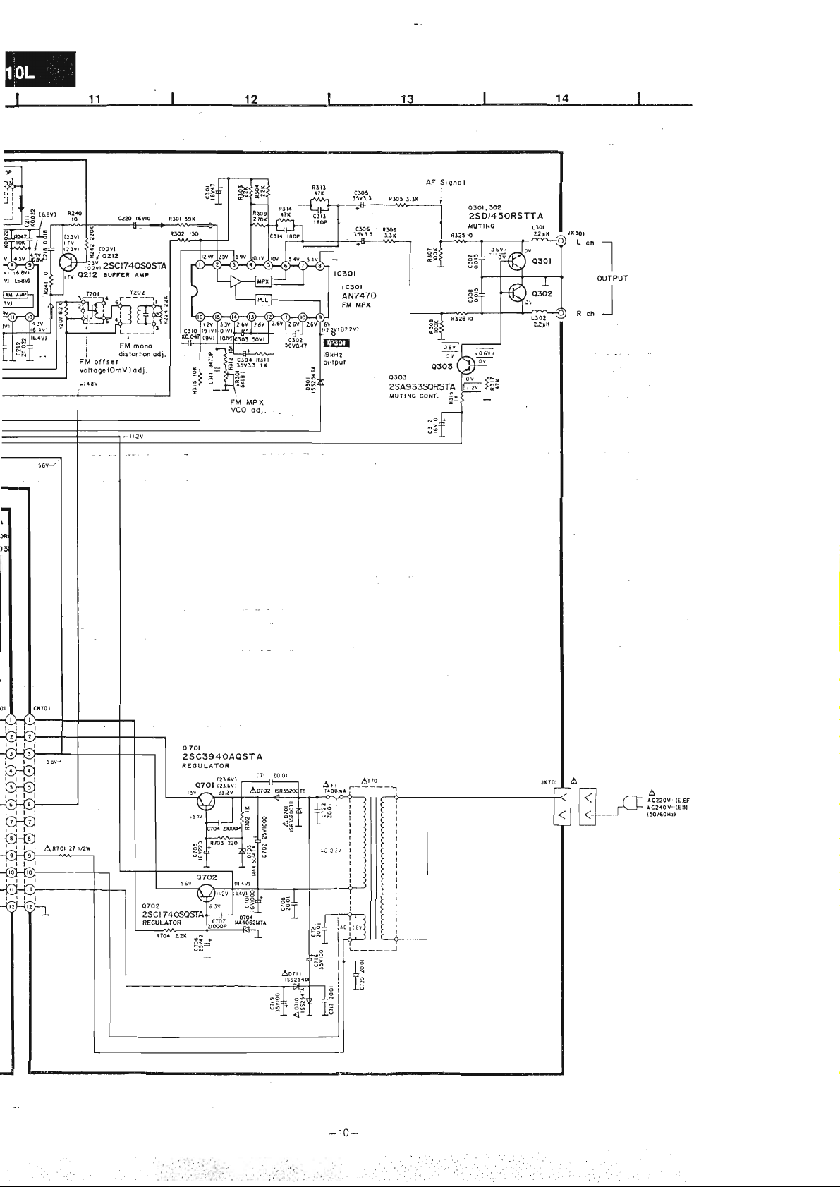
vl l
vl
fu] iEL
it
tswl
AF
Srgno I
ro?
o3or.
l6v1o
c220
Ý ro2vl
Ž
oztz
/
j/aiiY'
'ďl
Q2I2 AUFFER
N
zsctT4osostrA
filol ]9Í
AxP
25DI45ORSTTA
Llol
,lx!o1
u
Lch
"J"",
!rBg\.
_l
L----J-
i
,rl
oistortin
I
FM oíí5eÍ
Yoltogc(OmV)odl.
-iatv
'ono
ooi.
FM MPX
vCO
odi.
Llo2
22rA
Rch
o 70r
2SC3940AQSTA
REGU
LATOR
(21,6v)
OTOl rzr.svr
:5v
?!.2v
^
cTlr
loot
-'0-
-
Page 11
f
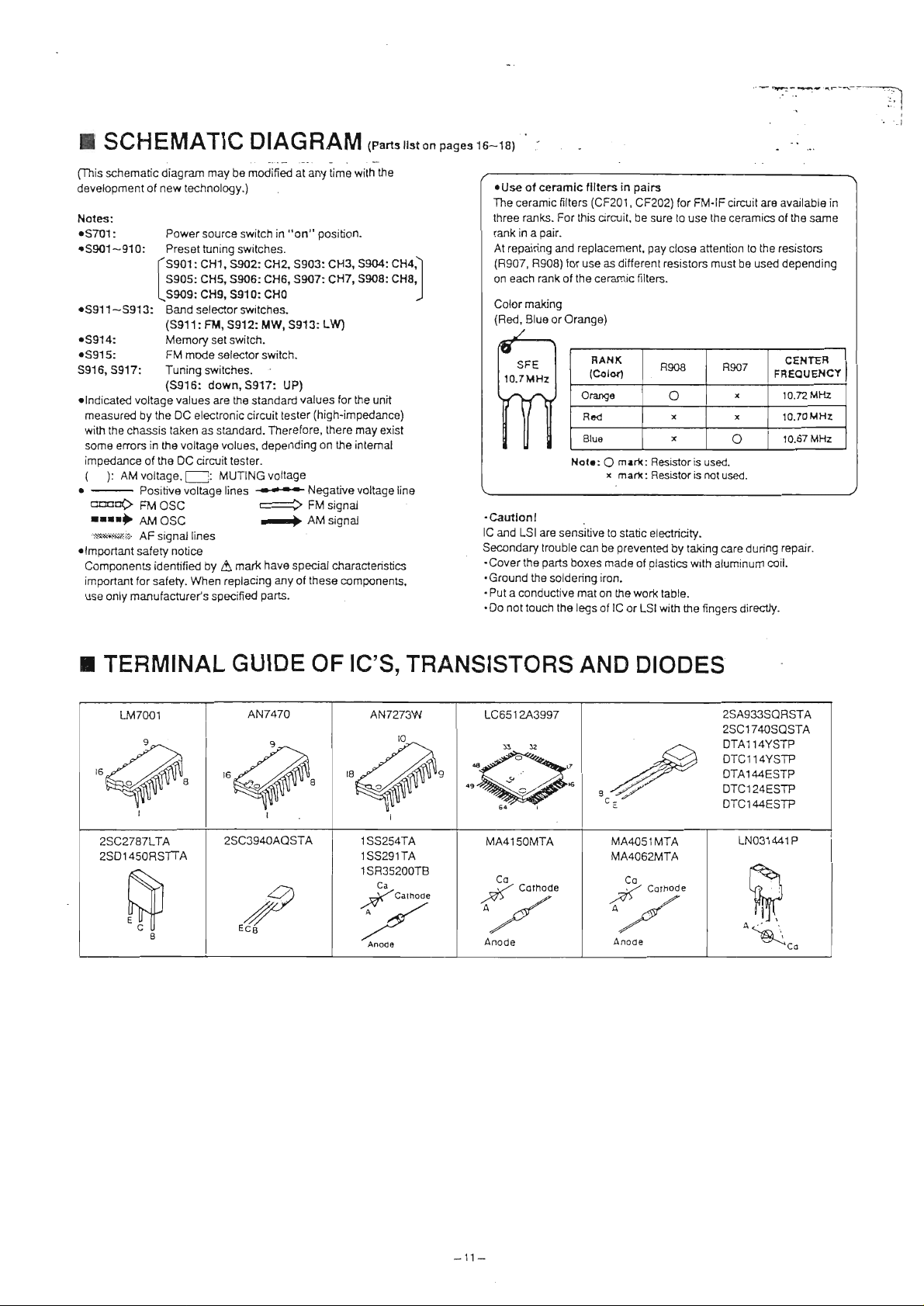
SCHEMATIC
DIAGRAM (parts
rtston
pases
16-18)
.-''-_s_.{r-Ť--
.
.,t
.::
I
I
.
|
.l
schematic
fl'his
development of new tecinology.)
Notes:
oS701
: Power source switch in
oS901-910:
oS911-S913:
oS914:
oS915:
S917: Tuning
S916,
olndicated
measured by
with
the
some
impedance
(
):
.
ctrtrtrD'
rrrr)
-
.:\Ťr*a_$&!i!'}.
o
l
mportant
Components identified by
important Íor
use only
diagram may be r"iin.a
Presettunings,witches.
CHl,
íssot:
ssos, cHS, s9o6: cHs, st[7: cH7,
I
l-ssos,
Band
(5911:
Memory
FM
(S916:
voltage values
the
oC electronic círcuit tester
taken
chassís
in the voltage volues,
erorc
AM voltage,[--i: MUTINGvoltage
oÍthe
Positive
FM
OSC
DC cirilittester.
5902: CH2' 5903: CH3,
cH9, S91o: cHo
selector
FM,
5912:
setswitch.
mods
selector switch.
sritches.
down,5917:
are
as standard.
vollage
lins5
AMOSC r+
AF signal
saÍety
lines
notice
A
When replacing
safety.
manufacture/s
specified
"i"ny
position.
"oÍl''
switches.
MW,
5913: LW)
the
marX have
UP)
standard
values
(high-impedance)
Therefore, there
depending on the intemal
.-
parS.
Negative voltage
AM
specialcharacteristics
any
these
oÍ
iime witn ne
5904: cH4)
sgoo: cHB,
for
unit
the
may
signal
components,
exist
line
oUse
oÍ ceramlc
The
ceramic
ranks. For
three
pair.
rank in a
At repairing and
(B907,
R908)
rank
each
I
)
on
Color
(Red,
making
Blue
Íllterc
filters
this orcuit.
replacement,
Íor
use as difÍerent resistors must
oÍ the ceramic
or Orange)
Orange
Rcd
Blue
Nolr:
(CF201'
RANK
(coloÍ'
O
x
in
mert:
mart:
pairs
cF202) for
be sure to use the
Íilters.
FM-lF
pay
closa attention to
8908 R907
o
x
x
Resisloris
Resistor
is
used.
rxrt
circuit are available ín
ceramics
o
used.
be used
x
x
of the
the
resistors
depending
cENŤER
FBEOUEI{CY
10.72 MHz
10.70MH2
10.67 MHz
same
.Cautlonl
lC and
LSI are
Secondary
.Cover
the
.Ground
.
Put
conductive
a
.Do
touch the legs
not
sensitive to
trouble
parts
boxes made
tha soldering iron.
can
mat
be
on
oÍ lC
static electricity.
preventd
the work
by taking
oÍ olastics with
table-
with
or
LSl
care during repair.
aluminum coil.
the fingers
directly.
r
TERMINAL
2SC2787LTA
2SO14s0RSTTA
GUIDE OF IC'S,
25C3940AQSTA
1SS254TA
rss291TA
1
SR35200TB
a
v
ecá
TRANSISTORS
AND
MA4O51MTA
MA4O62MTA
-4Ž
A
Anode
DIODES
LO
,/
Cothode
.<{
2SA933SQFISTA
2SC1740SOSTA
DTAI 14YSTP
DTCI 14YSTP
DTAI44ESTP
DTC124ESTP
DTC144ESTP
LN031441P
tq
víT/
oti(,."
-11-
Page 12

r
ctRculT
BoARDS
OPERATION SWITCH PC B.
AND WTRING
CONNECTTON
aNr
Í_{?5o-
I
r
l-FM
6N0
AM
l
líAM
lANrll
DTAGRAM
LooPl
ANr
I
(pa
['
lo
I
l=
l.
Á
l:I,
lÍl
lrh
lel-
lol
lÍi
lEl:
lzl
l<l
lěl
lcl
Lr_
l=
I
LED
FM
P.C.B.
/!
IEA @I
olí'.l \alloo.
íomvl
I'
L=
Page 13
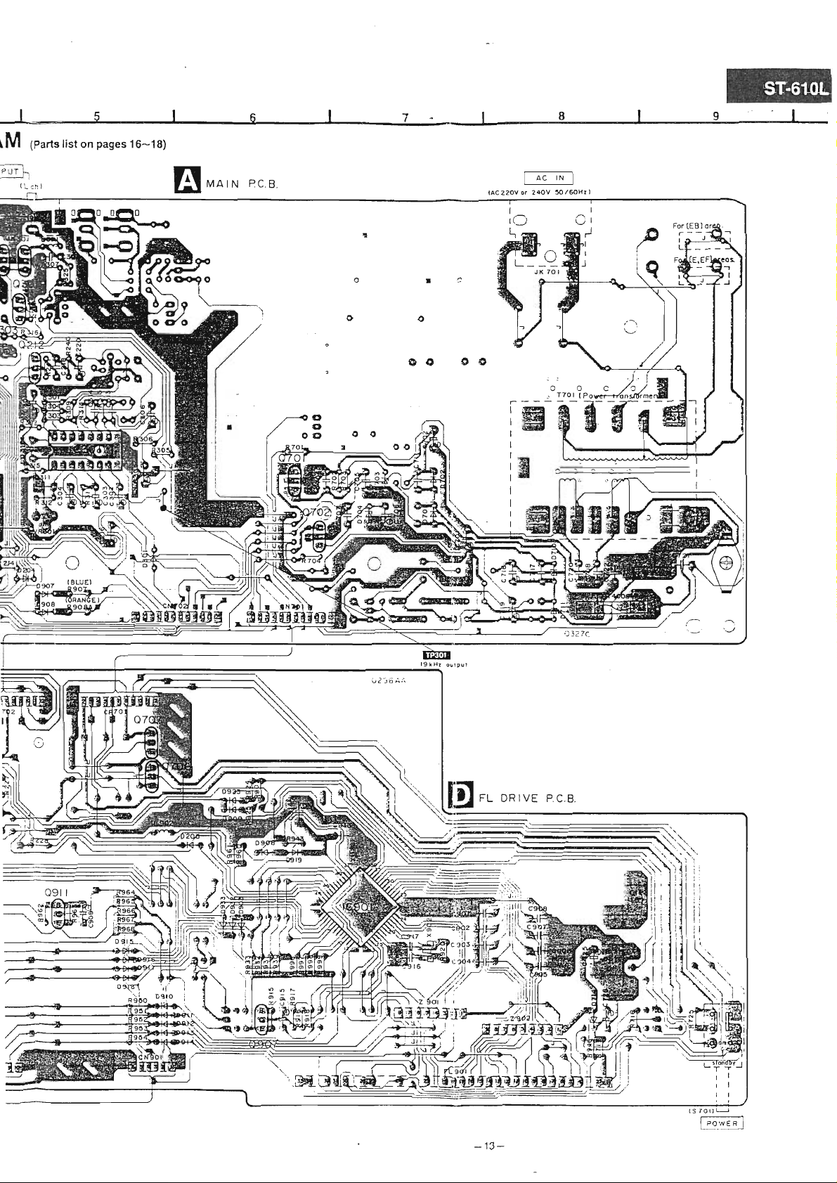
J-slsl r8l
\M
4
9.
ol
(Parts
llst
on
pages
16-18)
MA
IN
PC.B.
ÍD0 o0
(ac220v
rN
ac
240v
I
3'o/60Hrl
f
or
MII
Í/-.s
iiiíl,aa''r*
ub>
r. l_
íT\
-.,
h\-LJ
.BiT.
D{
[!l
r. DRrvE
-'t3-
Pc
9l!.
'
B
"fi
l!
rth.
l'r
\-'
!----.\
ti
\N
q'-{j
!
Page 14
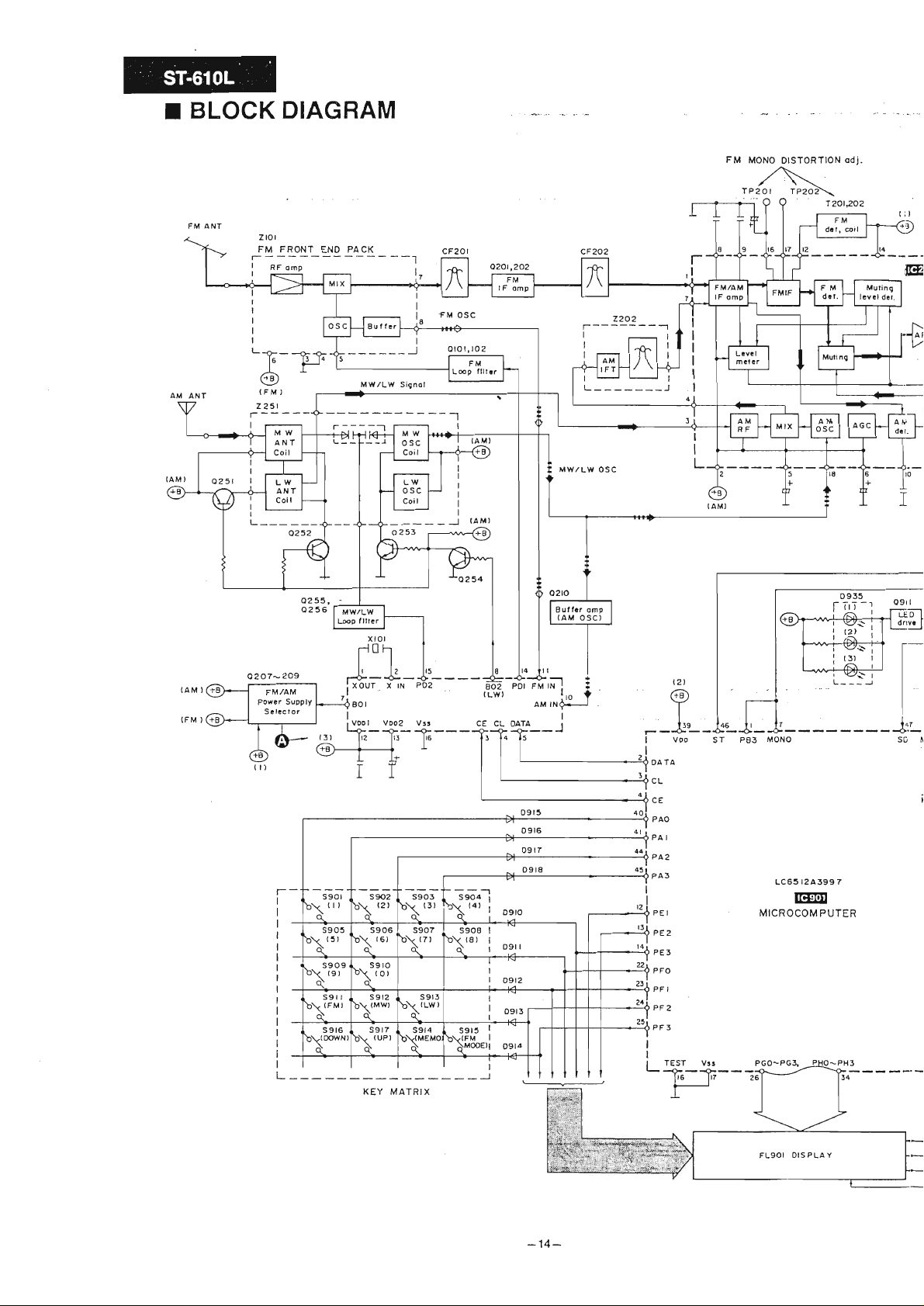
I
BLOCK DIAGRAM
rol
z
FRONT
FM
'Á_T$
)
IFM
z2sl
r----
0255,
0236
ENO
r-.----l
PACK
8uííer
MW/LW
Signol
Í...:r
LW
osc
Coil
fM
olotr to2
--1
osc
l
I
L---_-_-J
MW/LW
Buíí.' omP
(AM
OSC)
u
OSC
z2o2
FM
MONO
DISTORTION
,N
TP2ol
I
I
I
TPzož\
odi.
L
-i15-l
dn:1r
o2o7-
2O9
T---TTT
\ŤT |{'z; J.{LlF{i".r
s905
(3r
o\
č
s909
(st
b\
o\
s9r r
bxFM'
\oo.íNl
iťf
b\ (ot
d
r\'ds
b\
N
KEY
s9lo
s9r7
(uP)
s907
b\
\
ť]]
MATRIX
(zr
sgrs I
o\
s908
q
t-
I
I
l"z
SO
M
!'o Ý
I
J
t-
a
--rt
-1
--t
40i
4l r
rlrl
?3
2a
t2
ll
t4
t-
r
OATA
CL
CE
PAO
PAI
PA2
PA3
PEI
?E2
PE3
PFO
PFI
"F2
PF3
12,
?t
trE lcs
-<E
VOO
-ab:-
-
ST
PBs
MONO
Lc63
r2A399
7
tr@
MICROCOMPUTER
(Lwl
CE
tt
lt
tt
I
tet
CL
OATA
>{
Er
-
o9-lo
o9t
09t2
osl5
o916
oslT
0918
.
r
aM INQ+-J
-O--
rurx ! !
POI
aoa
,",.1t-
rEsT
I
l
-
vtJ
-ji'--ft--;;Ý-
Í
l4
--t
Page 15

I
:
''
r il
{)
FMIAM
------]
&Et
I
I
-ÁN7273w
trEt
tF AMq oET
+-
r----
l5
aN7470
lEttr
FM MPX
vR30l
MPX,vCO adl.
MPX
TP 30I
vCO
odl.
R3t4
c3r4
o303
'":"1",
a",
-l
{.t lr.
_o'.-.Ó'.-
so mu-re
ni:S
-
_._
Hol-DÓ_
osc'
o.".fLf
RLY
I
!'si
--
:37
l4-.1
lo
35
!
x902
(
960 kHr I
0706,707
(POWER
ON
s70l
)
o7or,702
oTto,71r
Notc:
í--:;-
:
!!!o
I
:
I
a
L:'::ť-(:Yy]
FM
AM
'is^"l-
osc
(LW/MW)
-
rtqnot
1'j
--l
I
j
15-
-
Page 16

HEPLACEMENT
I
Notes:
"'
lmportant
Components
only
'The
Parts
'"K" mark
..'s"
Parts other
{!:
safetY notice:
identified
manufacturer's
parenthesized
without these
parts
parts
mark
than
lndicates
parts
indications
indications
used for
are
used Íor
are
"K'and
that are
by
A
speciÍied
"S''
black type only.
silvertype
supplied
PARTS
mark have specíai
parts.
in
Remarks
the
used
can be
marked are used
íor
only.
PFS. (Panasonic
by
LIST
characteristics
columns specify
all areas.
Íor all color types.
France
important
the areas.
S.A. Longwy
for
saíety.
(ReÍer
When replacing any
lo
cover
the
division).
page
for
of
area.)
these
components
use
Ref.lb.
ICl0l
IC201
IC30I
ICg0l
u()l102
)20r,202
1203
120s
1206
l?07
u08
120s
)2r0.2r2
u51
)?sL253
12s4
256 2SC1740SQS[A InÁNsIsToR
1255,
1301,302
1303
l70r
1?02
1706
1707
1907
1911
)101
)204
)206
)301
)70r.702
)703
0704
)710,711
D7
t4 líA405IIíIA
D903
0907,
908^
Part No Part llam &
[.tl7001
N7273r
AN7470
lC6512A3997
zSC1740Sq$A IRAI{SISMR
2SC2787tTA
2SC1?4{NqSIA IM}ISISTOR
zSC174oSQSIA
DTC124ESIP INANSISMR
2SC1740SQSrA INAilSISMR
AA933SQRSTA IMI{SISMR
DTA144ESTP
zSC1740SQS[A
2SA933SQRSrA TMNSISMR
zSC17{NQSTA
D(Cl14YSIP
25D1450RSnA IMNSISTOR
2SA933SQRSIA
2SC3940A{SrA
zSC1740SQSrA
mAll4YSfP TNAilSISTOR
mcl44ESIP TRAI{SISTOR
2SC1740SQSrA
2SC1740SQS[A
1SS254TA DIODE
1SS254TA DIODE
1SS254TA
1SS254TA
tsR35200TB
r{A4t50il|IA
[A406aíIA
1SS254TA DIODE
tsszs4TA
lss254TA DIODE
Descriptior
INTTGRATED CIRqJIT(S)
IC,
PLL
FREQIIEI{CY
Ic.ril/Ail
IF ÁtlP. DET
IC,
FH HIX
Ic'l'{IcRm$íRnER
IMNSISTOR(S)
INANSISMR
IBANSISTOR
mÁNsIsToR
TMNSISTOR
INANSISMR
IMIISISTOR
IMT{SISTOR
MANSISTOR
IMNSISTOR
IBAI{SISTOR
INANSISTOR
(S)
DIODE
DIODE
DIODE
DIODE
DI ODE
DIODE
DIODE
DIODE
Renarks
Ref. No
)908-918
)919 1SS291TA
)923 1SS254TA
)93e
$3 1SS254TA
)935
m01 EvNDxÁAoo853
Part lb. Part Nane
1SS254TA
u{03144lP
DIODE
DIODE
DIODE
DIODE
LE.D.
VARIABLE
V. R. FIl ilT(
cu'íP0mm c0[lB IMTI 0l{
1101 M[0006
l20L RlÁ6z001-T
t"202
190
1902 DGFgElMJ
rF20r RLFKTFzIO2I,A CERA}IIC FILTER
rF201
1F201
)F202
iF?02
Ril22003M-T
EGFSEi04J
1
RLFKTFzMzLB CERAIIIC
RI.FKTF2II[2LC
H.FnFzlit]2lÁ
RLFKIFzMztB
CffiPOMNT
c$tP0NEt{T c0lts I MTI 0t{
CffiPOMNT
c$íPomilT c0ilBIMTIoll
COr{POl{EliT C0}ts I MTI 0N
FILTER(S)
CERAIIIC FILTER
CERA,\{IC
CIffAIIIC FILTER
& Description
RESISMR$)
VCO
COTtsII{ATIOII
COMBIMTIOI'l
FILTER
FILTER
ADJ.
(s)
iF2g2 RtFIflFzMzLC CERA,\IIC FILTER
(s)
corL
.101
.104 RtQZPR2z!fi-Y
.20J,m4
.301,
,902
t201
A
t29Z RL t48003-Z
t701 RTPlK4IOII
A
(10
(902
RtQZPR4TKT-Y COIL
ELEPKN2AU
302 BtQZPzR2KT-Y
RtQZPl0llfi-Y
Rt I48002-Z
t svQ4su722T-S
EF0A960l0l4A
COIL
COI
L
COIL
COIL
TRANSFOffiER(S)
TRAI{SFOffiER
TRANFomíER
PÚIEB
TMNsFoR}ltR
6CrLI.AT0R(S)
OSCILLAMR
OSCILL,\mR
Renarls
(NED)
(BLUE)
(oMlfrE)
(RED)
(BtUE)
(oMilGE)
A
-16-
Page 17

Ref. No Part l'la Part
llam & Descripticn Renarls
Reí }lo Part ltb.
Part
&
Nane
Description Renarks
DlsPláY TUBE
il901 SAD8}íI10zYl( DISPUY NEE
ilITCH(ES)
s70l
s901 EVQ2140sR $í'
s902 EVUl40sB
sg03
s904
s90s EVQz1405R $r, ct6
sg06
s907
s908
sg0g
s9l0
s9ll EVQz1405R
s912
ss 13 EVQzl{05R S[T. BAND LIT
ssl4 EVQz1405R
RSmB00l-J s[, PÚIEB
cHl
CI?
Str,
EVQz140sB sn,
EVQz1405R sw' cM'
EVQ21405R
EVQ21405B sn, cHn
EVQz1405R sw.
EVQz1405R sir. cru
EVQz140sR sY.
EVQz1405R s[t' BAliD ltílÍ
clB
cH6
stv,
cH8
clu
BAI{D
ST,
sn' [{BoEť
FM
s915
1916
s917
JIO{)l
A
Jn(lt
It001
EVQz1405R SII,
EVQz140sR $T,IUNING MW
EVQ2140sR SIT,
RJM2(l2
RrE320lr{
sts9236
JM04 EYFSzBC RSE }PLDEB
Jto05
cN701,
;!{901
:N902 R.nn03K010Ir1
tP70l, 702
tP902 R.JT003K010il1 C0NNEC[0R(10P)
1P903
EYFSzBC
702
ulmS[012 SMIGT(I2P)
Rnno3K00ffil
R,JT00srT0l2
RtT003K00ilu
F[l
IIODE
IUNING
UP
JACK(S)
A}ÍffJ{l{Á TEm{IilAL
ilITRJT
TERMIML
m flJftn
F(sE rcMER
smrcT(6P)
ffircT(10P)
coNmcToR(12P)
coNmcToR(6P)
A
A
A
FtsE(s)
:l
EMC04TB()
R.SE 250V 0.4A
A
r
Notes :
_+
Bef.lb.
R101,
r02
Rl04 EBNzTJÚn L/4n
Rl05 ENNNJ561T r/Av
Rl06 ERNNJSEN
Rl07 ERN2TJ1ON
Rl08 ERNZTJlSlT r/4v i50
M01 ERNZTJlSN
pa02
R203 ERNNJMIT t/4v 330
R204
M05 ERNNJillT L/AV 330
M06 ERNNJ561T r/4v s60
8207
MOB
R209
flzLZ ERDSzTJI53T
Capacity
Resistance values are in ohns, unless
Part [h
mN2TJ10íf
ERN2TJ824T
ERNNJ474T
ERN2TJS2ZT r/Av
ERNruM2T
EBN2TJ47lT
Ml3 IRDSzTJlO4T
M1{ ERN2TJ824T
M16
R2
18 ERNzTJ563T
TRDS2TJS6N
valuse
Values
RESISTORS
r/Av
L/4V
L/AY l()K
L/4V 1.
L/AW B20K
L/AW 470K
L/4fl
L/4V 470
L/4v
UI l00K
L/
L/4W
t/Av
L/4W
are
10K
560
s.6K
8.2K
820K
56K
56K
IK
sK
l5K
&
IK
Renarks
ricrofarads
in
(uF)
unless
specified
Ref. No
R219 iRDS2TJ223T 1/4fl
R?il
specified
otherrise,
Part ib.
MDSzTJI()3T L/Afl
otheryise' P=Pico-farads
lK=l.
Values & Beoark
PAzt ERDSzTJl{}4T L/4r
R223
p224
PC25
R227 ERDS2TJl04T
ERDSzTJ47lT
ERDSzTJz22T L/4V
TRDS2TJl04T
r/4fl
t/Av l00K
L/4fl l00K
u28 ERDSzTJl23T r/4fl
R229 ERDSzTJ822T
R230 ERDS2TJlO4T
R231
t23Z
R233 ERDSzTJ684T L/AW
M34
R235
M36
R23?
R240.
R242
R244
R247
R251
R253
ERDS2TJl02T
ERDSzTJl22T
ERDSzTJIO3T L/4W
ERDSzTJ4TIT L/4W 4t0
ENDSzTJ333T t/4w 33K
ERDSzTJISIT
241 ERDSzTJIO{)T
ERDSzTJ22{T L/AW
ERDSzTJ822T
ERDSzTJlO3T l/
ERDS2TJlO3T
EROSzTJIszT r/4w
L/4V
Í/qfl
L/Att
r/4\l
r/AJ,t
L/4W
L/4fi
\t l()K
t/4w
000(0HX),
22K
10K
moK
470
?-2K
12K
2K
&
100l(
1K
l. 2K
6B0K
loK
150
10
?20R
& 2K
loK
r. BK
(pF)
ť=Farads
000k(OHt)
1X=1,
Ref. No.
R254 ERDSzTJzz 3T r/4fr
R256 ffiNzTJI()2T
R258 ERDSzTJUN L/Afr
R261 ERDS2TJlO2T
R262
R263 ERDS2TJ15ÍT
R264 ERDSzTJIO2T
R301
R302
R303. 304 ERDSzTJzz3T r/4w
R305.
R307,
R309 ERDSzTJ274T L/4V
R31l
R312
R313,314 ERN2TJ47N L/*t
R3l5 ERDSzTJIO3T t/Aw 10K
R316
R3r7
R325, 326 ERNzTJIOOT L/4\t
R70 1 ERDSlFVJzTOT
R702
R703 ERDSzTJ22lT l/4w
ERDSzTJNN L/4W
EBDS2TJ393T
IBNzTJISIT L/4W
306
ERDSzTJ33N r/A\t
TRNzTJlO4T L/4W
308
ERDSzTJION
ERNzTJl53T L/4W
IRDSzTJlON
ERDSzTJ473T L/AW
ERDSzTJlO2T
(F)
Part lb. Values & Reuarls
L/AV
L/4r
L/Afl 15K
Li4V
L/Afr
r/4w
l/4w
r/4w
L/AUt
22K
lK
r.zK
1K
3.3K
1K
39K
150
?2K
3.3K
r00K
270K
1K
15K
4lK
1K
47K
t0
?7
IK
224
Page 18

Ref.Ib. Part
l,h Values &
Renarls
Ref.lib.
Part lb. Values & Reoarls
2.2K
701 ERNNJ22N
716.717
725 ERNNJ1OsT
902
907. 908 EBDzs\roM()T
915 EBN2TJ82lT
916 ERNZTJ2T2T
917 [nNnJ103T
918
920
924 ERNNJSgN r/Av
925 ERNNJ473T L/4V AlR
930- 933 ERNNJ1O4T L/An r00K
943 ERN2TJlO3T L/Afl
946 mNnJt0lT
950-954 ERNNJ683T L/AW 68K
960 ERNNJl()ST
961
962
963 ERNNJ563T L/4W
964
965 ERNNJUN L/4tt L.zK
966
967 ERNNJ18lT
968
996-999
101. 102 ECB[1Hl50JC5 50v rsP
103 ECB[lC103rS5 16V 0.01u
105
106. r07
108 ECEAlEK4RTB 25V 4.7U
ERNNJI()IT
ERN2TJ1O4T
ERN2TJ224T
ERNZTJI()ST
ERNNJz?3T
ERNZTJlS2T
ERNZTJS6lT
ERNNJz2lT 1/4V
ERNNJ33lT r/4n 330
ERNNJlO4T L/4n 100K
EcEáoJUIo1B
ECmffi103ZE5
t/Afr
L/4W
L/Afr 10K
100K
r/Aw
t/Aw
L/4fl
2.?R
L/Afr
L/Afr
L/4V
220K
L/4v 1H
3.9K
r/Aw 100
t/4v 10K
L/4fr 21K
r/Afr
L/4W
l/4Í 1B0
;APACITORS
6.3V
50v 0.otu
100
820
l()K
10K
1.8K
s6K
s60
220
l00u
l0g EcEÁ1cU330B l6v 33U
116
zll.2g2
203
za4
205 ECtfi1H223ZF5
206 ECB[1H150JC5 50v lsP
208
209
ll0.211
,.12
!13
,-L4
115 ECBTlC103t65 16V 0.01U
Ir6
tL7
!lB
ll9
Ecín1H103ZF5
ECmffi103ZF5 50v
ECBr$8R2KC5
ECBTlCl03Ns
ECEAO.IUI()IB
ECEAlEK4RTB 25V 4.7U
ECFRlE2NM
ECWLEU3ZTS
ECBT1Hr01t65 50v 100P
EcFálcK100B
ECEAlCKl()OB 16V rou
tcEAlHtol0B 50v 1U
ECFRlElE3rfr
tcBÍlc103l{s5 t6v 0.01u
50v 0.01u
0.01u
50v 8.2P
16V 0.01U
sov
0.022u
6.3V
25V 0.022U
25V 0.022U
16V rou
25V 0.018U
100U
c220 ECEA1CK1()OB
c222
c225 ECBnCl03NSs
cu6
0
cuL
c251
c2s2 ECEAltilOl0B 50v 1U
c253
;$l
302
;$3
)304-306
c307.308
1310 ECIRIE473KR 25V 0.04ru
:311
;312 ECEA1CKl(]()B
1313. 314
1701
j?0?
i?04
r705
)6
i707
1708
1711
1716
)71?
1719
)?m-I22
i725
i?26
ls0l-908
lg09
l9t3
1914
tgrS
1916
l9l7
ECFRIE4T3KR
ECBT1Hl8OJC5 50v 18P
ECBTlCl03NSs 16V 0.01U
ECKRltEz3ZF5 50v 0.02a,
ECKRIIPz32FS 50v
ECEAIq'4708
ECEAlilfr4?B 50v 0. dru
ECEAIt[CI108 50v lU
ECEAIVI$MB
ECFRTElS3KR 25v 0.01íJ
ECQPl47lJZ3
ECBTIHISlKBS 50v 180P
ECEA1A'222Y8 16v
ECEA1zu102B
EC|G1H102ZF5. 50v
ECEAlflJ221B
ECEA1EK4RTB
ECKRIHl(]22FS
ECKRIl{1032F5
ECKR1Hl()32F5
ECEA1WlOlB
ECKBIHl()32FS
ECEA1Wl()lB 35V 100tt
ECKR1Hl()32F5
ECEA1V{O008
ECEATVI$R3B 3sv
ECKRlH331KBs
ECEA1EK3R3B 25V 3.3U
tcKR1H103ZF5
ECEAÍ)JUl()2B
ECEA1I[822 B 50v 0.2n
ECBTlHl()1KB5
ECBT1HI2lKBs
16V
0.04ru
25V
161t 0.01u
0.02zu
16V 47tJ
35v 3. í'
50v 470P
1611 10U
?mÚJ
25V
1000t
1000P
16V 220U
25V 4.ru
50v
1000P
50v 0.01u
50v 0.01u
35V 100U
sov
0.0lu
50v 0.0Iu
3sv
3.3{J
50v
330P
50v 0.01u
6.3V
1000u
50v 100P
50v
120P
10U
10u
18-
-
Page 19

Ref.ltb. Part I'b.
Part Nare & Descriptim
Reoarls
tuf. No
Part lib. Part ltbne &
Description
.
Rena*s
cABImÍ PAnÍs
Rr00032-K CABINET
Rlsí]032-s CABINET
sl{E2129-1 sREÍ
st{82129
IffBS3+&JFZl scREn
mR008ltrc
RGno081trA
RťIGÍI610LEF REAR PANEL
RGWO30 RnÍEB BmT0N
RGU()030-S
RFKJT6l()LE-K
6-l
Rt$0009-1
R[lm145
míRo277
I RFI(GT6IOLE-K
s
10
l0
11 mn357-K
11 RGtn357-S
T2 RGU()358-K
L2
mrcT610LE-S FRONT
RfKI{T6lOLE-K
RFt0{T6t0LE-S
muo358-s
scREÍ
REAR PAI{EL
REAR PAI{EL
POf,ER
CHASSIS ASS'Y
:0m
il,BBER
FL HOLDER
IRONT PANEL ASS
FRONT
IROI{T GRILL
ruNING B{JTTON
ruNIrc
;HAilML iliTMN
ÍtAt{l{EL BmmN
l3 Rnn360-K MDE
l3 RGU(}360-S
14
15 KIBSZ6+&I
sl{E187-2 IPLDER
l6 XtB3+20JFZ
MDE
SCRET
SCRff
BUTTON
PANEL
GRILL
ilNON
zulTON
zulTON
ASS'Y
ASS'Y
ASS'Y
PACKIIS MATERIAT
P1
P1
P1
P2 RPffi25
P2
(E)
(EB)
(EF)
E
Y
P3 SPSD152
P4 l{ZB52X60A01Z
A1 PQÁ0013
T2
\3 RFIST6lOLE-K
\3
\3
RPG{)493 CATTON
RPG&94 CARMN BOX
RPG()498 CARTON BO,\
RPN{)i24-l PAD
BOX
PAD
ACCESSORIES BOX
PÚTECIIoN covER
ACCFSSORIES
ťARRANTY
mcm16g
mms18-B
mT0712-F
sERvlcE}Ír0R
II6TRI.ITIONS ilAMJAt
IIsTRUCTION }IAI{UAI
INsTnUcTIolls
CARD
LIst
}{ÁNIJAL
t{ SFDAC()SE{)3 PoťER coRD
t4 SJAIg3
\5 stnz76
\6
t6- t $íA233-lil IOLDER
sPB1163T ilI LOOP ANTENNA ASS'Y
PÚťER coRD
ýtERt0 PIN
c0RD
(G
EB)
EB)
iG
(EN
(I
EB)
GDEl
(E)
(EB)
(EF)
A(8.ET)
A(EB)
E
E
\6-2 KII{3+10AFZ SCRET
t7
t8 sJP9009 ATTACT
ssA270ll
TII ANTENM
IENT
PLUG
(83.
EF)
Page 20

r
EXPLODED
VIEW
2
,,/.
@
\
\
6-
Prínted in
F900306300TWFF/rY
Japan
 Loading...