

Page 1
Service Manual
TOP NEXT
Order No. MD0004066C2
AV Control Stereo Receiver
SA-EX140
Color
(K) ... Black Type
E ... Europe
EB ... Great Britain
EG ... Germany and Italy
FM Tuner Section
Frequency Range 87.50-108.00 MHz
Sensitivity
S/N 30 dB
S/N 26 dB
S/N 20 dB
IHF usable sensitivity
IHF 46 dB stereo quieting sensitivity
Total harmonic distortion
MONO 0.2%
STEREO 0.3%
1.5μV/75Ω
1.3μV/75Ω
1.2μV/75Ω
1.5μV/75Ω (IHF’58)
22μV/75 Ω
S/N
MONO
STEREO
Frequency response 20 Hz-15 kHz
Alternate channel selectivity±400 kHz 65 dB
Capture ratio 1.5 dB
Image rejection at 98 MHz 40 dB
IF rejection at 98 MHz 70 dB
Spurious response rejection at 98 MHz
AM suppression
Stereo separation
1 kHz 40 dB
Carrier leak
19 kHz -30 dB (-35 dB, IHF)
38 kHz -50 dB (-55 dB, IHF)
Channel balance (250 Hz-6.3 kHz)
Limiting point
60 dB (73 dB, IHF)
58 dB (67 dB, IHF)
+1 dB, -2 dB
70 dB
50 dB
±1.5 dB
1.2μV
Bandwidth
IF amplifier 180 kHz
FM demodulator 1000 kHz
Antenna terminal 75Ω (unbalanced)
AM Tuner Section
Frequency Range
522-1611 kHz
http://schema99.host.sk/
Page 2
Sensitivity 20μV, 330μV/m
Selectivity (at 999 kHz)
IF rejection (at 999 kHz)
55 dB
50 dB
Amplifier Section
Power output
DIN 1 kHz (T.H.D. 1%) 2 x 100 W (4Ω)
40 Hz-20 kHz continuous power outputboth channels driven
2 x 80 W (8Ω)
Total harmonic distortion
rated power at 40 Hz-20 kHz 0.5% (8Ω)
half power at 1 kHz 0.07% (8Ω)
Power bandwidth
both channels driven. -3 dB 10 Hz-40 kHz (8Ω)
Damping factor
Load impedance
Front
Frequency response
30 (8Ω)
4-16Ω
PHONO RIAA standard curve (30 Hz-15 kHz)±0.8 dB
CD, TAPE, VCR
Input sensitivity and impedance
PHONO
CD, TAPE, VCR 200 mV/22 kΩ
S/N at rated power (8Ω)
PHONO 70 dB (IHF, A: 80 dB)
CD, TAPE, VCR 75 dB (IHF, A: 85 dB)
Tone controls
BASS
TREBLE
Output voltage
TAPE REC (OUT), VCR OUT 200 mV
Channel balance (250 Hz-6.3 kHz) ±1 dB
Channel separation 55 dB
Headphones output level and impedance
10 Hz-40 kHz,±3 dB
3 mV/47 kΩ
50 Hz,+10 to -10 dB
20 kHz,+10 to -10 dB
430 mV/330Ω
General
Power supply AC 230-240 V, 50 Hz (For EB only)
AC 230 V, 50 Hz (For E/EG only)
Power consumption 190 W
(in standby condition: 3 W)
Dimensions (W x H x D)
Weight
430 x 136 x 312 mm
7.0 kg
Notes:
1.Specifications are subject to change without notice./Weight and dimensions are approximate.
2.Total harmonic distortion is measured by the digital spectrum analyzer.
© 2000 Matsushita Electronics (S) Pte. Ltd. All rights reserved. Unauthorized copying and distribution is a violation of law.
@
TOP NEXT
http://schema99.host.sk/
Page 3
7 Troubleshooting
TOP PREVIOUS NEXT
This unit has test points on each circuit board block for use in troubleshooting.
7.1 Connection
7.2 Required items
7.3 Test Procedure for Amplifier Circuit
7.4 Test Points Positions of Amplifier Circuit
7.5 Normal Waveforms of Amplifier Circuit and Likely Faulty Blocks
7.6 Circuit Blocks
@
TOP PREVIOUS NEXT
http://schema99.host.sk/
Page 4
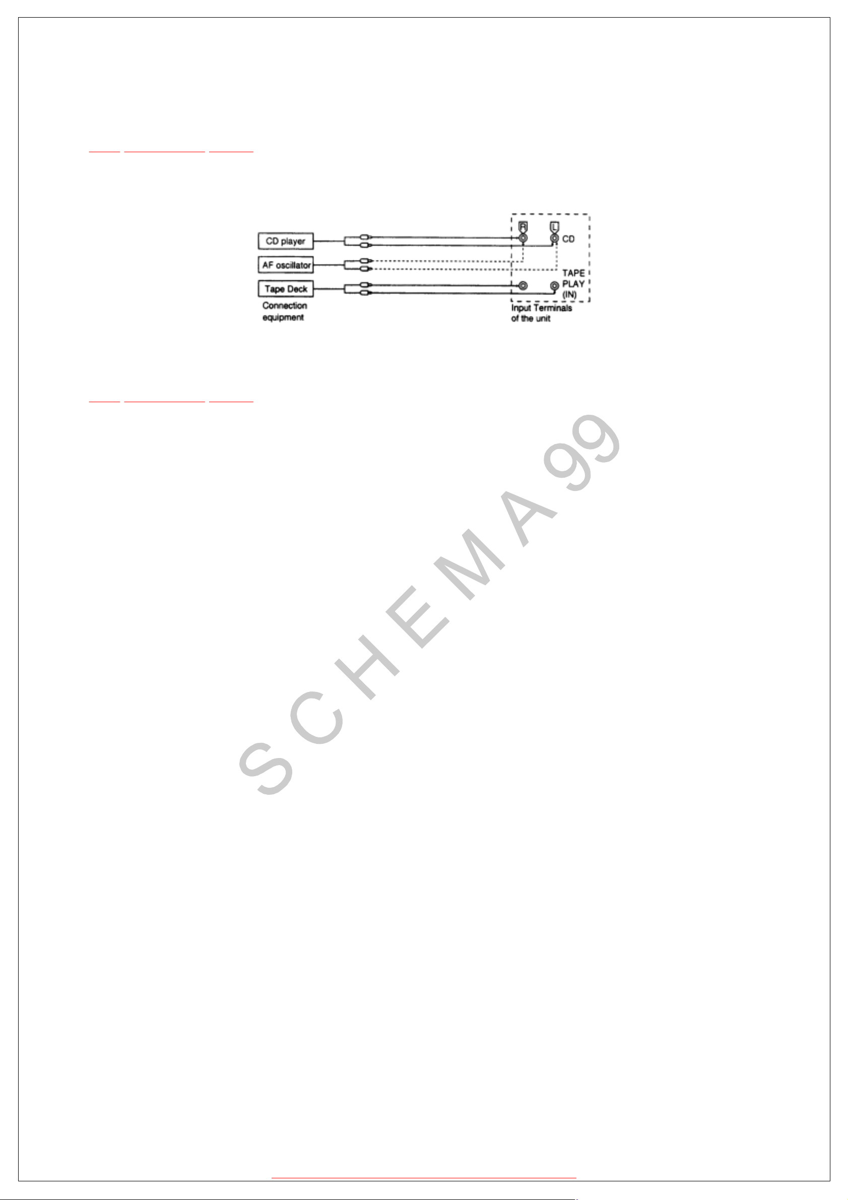
7.1 Connection
TOP PREVIOUS NEXT
Connect either a CD player, tape deck or AF oscillator to the input terminals of the unit.
@
TOP PREVIOUS NEXT
http://schema99.host.sk/
Page 5

7.2 Required items
TOP PREVIOUS NEXT
1.Testing with a CD player ---------- Test disc (SZZP1054C/ first program, 1 kHz, 0 dB)
2.Testing with a tape deck ---------- Test tape (QZZCLA/ 315 Hz, 0 dB)
3.Testing with a AF oscillator ---------- Set the output at 500 Hz, 200 mV
4.Oscilloscope (min. 10 MHz) ---------- To measure the output waveform at the test points.
@
TOP PREVIOUS NEXT
http://schema99.host.sk/
Page 6

7.3 Test Procedure for Amplifier Circuit
TOP PREVIOUS NEXT
@
TOP PREVIOUS NEXT
http://schema99.host.sk/
Page 7

7.4 Test Points Positions of Amplifier Circuit
TOP PREVIOUS NEXT
@
TOP PREVIOUS NEXT
http://schema99.host.sk/
Page 8

7.5 Normal Waveforms of Amplifier Circuit
and Likely Faulty Blocks
TOP PREVIOUS NEXT
@
TOP PREVIOUS NEXT
http://schema99.host.sk/
Page 9

7.6 Circuit Blocks
TOP PREVIOUS NEXT
@
TOP PREVIOUS NEXT
http://schema99.host.sk/
Page 10

11 Schematic Diagram
TOP PREVIOUS NEXT
(All schematic diagrams may be modified at any time with the development of new technology.)
Notes:
Power Switch
S946
Phone Switch
S947
Muting Switch
S948
S950
FM Mode Switch
Band Switch
S951
Tuning Down Switch
S952
Tuning Up Switch
S953
Memory Switch
S955
S956
Channel Down Switch
Channel Up Switch
S957
S960
Tuner Switch
S961
CD Switch
Tape Monitor Switch
S962
S964
VCR Switch
Search Switch
S970
EON Switch
S971
S972 PTY Select Up Switch
S973
PTY Select Down Switch
Display Mode Switch
S974
Speakers A/B/OFF Switch
S980
http://schema99.host.sk/
Page 11

The voltage value and waveforms are the reference voltage of this unit measured by DC electronic
voltmeter (high impedance) and oscilloscope on the basis of chassis. Accordingly, there may arise
some error in voltage values and waveformsdepending upon the internal impedance of the tester or
the measuring unit.
...FM
< >
...AM
( )
Importance safety notice:
Components identifed by mark have special characteristics important for safety. Furthermore,
special parts which have purposes of fire-retardant (resistors), high-quality sound (capacitors), lownoise (resistors), etc. are used. Whenreplacing any of components, be sure to use only
manufacturer’s specified parts shown in the parts list.
Caution!
IC, LSI and VLSI are sensitive to static electricity.
Secondary trouble can be prevented by taking care during repair.
Cover the parts boxes made of plastics with aluminium foil.
Put a conductive mat on the work table.
Ground the soldering iron.
Do not touch the pins of IC, LSI or VLSI with fingers directly.
@
TOP PREVIOUS NEXT
http://schema99.host.sk/
 Loading...