

Page 1
AV Control Stereo Receiver
Operating Instructions
Model No.
SA-DA10
SA-DA8
The photographs show the gold version of SA-DA8.
Model SA-DA10 is only for the United Kingdom.
The black version of SA-DA8 is only for the United Kingdom.
EB GN
Note:
“EB” on the packaging indicates the United Kingdom.
Before connecting, operating or adjusting this product,
please read these instructions completely.
Please keep this manual for future reference.
RQT5518-B
Page 2
Dear customer
Thank you for purchasing this product.
For optimum performance and safety, please read these
instructions carefully.
These operating instructions are applicable to models
for the United Kingdom, Australia and New Zealand,
however, are intended primarily for the United Kingdom
model.
Table of contents
Caution for AC Mains Lead ............................................. 3
Safety precautions ........................................................... 4
To enjoy surround sound ................................................ 5
Front panel controls......................................................... 6
Concerning the remote control....................................... 9
Connections .................................................................... 1 0
Connecting a DVD player .......................................................... 10
Connecting video equipment ..................................................... 11
Connecting audio equipment..................................................... 12
Antenna connections ................................................................. 12
Connecting the AC mains lead and other information .............. 13
Speaker connections ..................................................... 14
Placement of speakers .............................................................. 14
Connecting speakers ................................................................. 15
Preparatory steps ........................................................... 1 7
Speaker settings ........................................................................ 17
Adjusting speaker output level .................................................. 19
DSP sound modes .......................................................... 20
Enjoying the sounds ...................................................... 22
To enjoy bi-amp sound .............................................................. 24
To adjust the tone quality .......................................................... 25
To adjust the sound balance ..................................................... 25
When using the VCR 3 terminals .............................................. 25
Switching DVD analogue input ..................................... 26
VGCA mode ..................................................................... 27
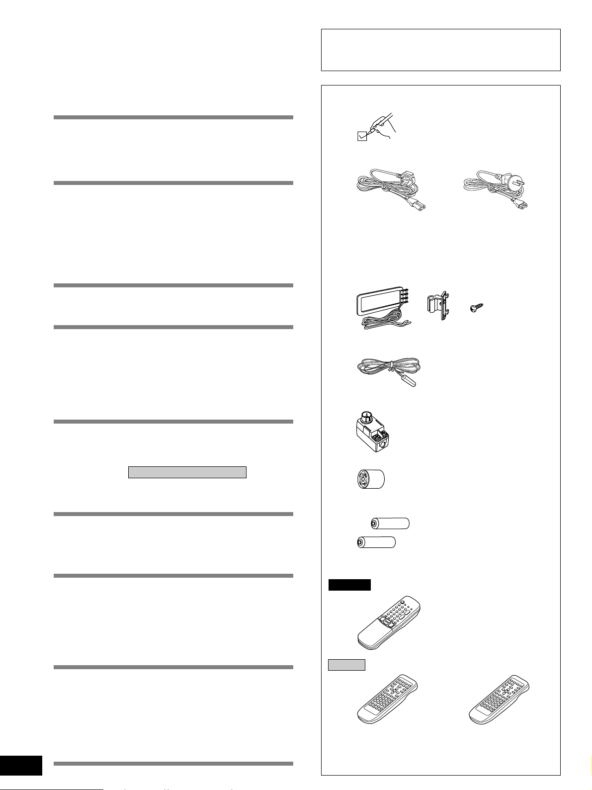
Supplied accessories
Please check and identify the supplied
accessories.
M AC mains lead .................................................................... 1 pc.
For the United Kingdom For Australia and New Zealand
(VJA0733) (RJA0035-X)
M AM loop antenna set
¡AM loop antenna ............................................................ 1 pc.
¡AM loop antenna holder ................................................. 1 pc.
¡Screw .............................................................................. 1 pc.
(RSA0012)
MFM indoor antenna ............................................................. 1 pc.
(RSA0007)
MAntenna plug ....................................................................... 1 pc.
2
RQT5518
The radio.......................................................................... 2 8
Sequential tuning ....................................................................... 28
Direct tuning ............................................................................... 29
Preset tuning.............................................................................. 30
RDS broadcasts Only for the United Kingdom ............ 32
To display RDS information....................................................... 32
PTY search and EON tuning ..................................................... 33
About the PTY display ............................................................... 35
Other functions ............................................................... 36
To listen through headphones ................................................... 36
Dynamic range compression ..................................................... 36
To mute the sound level ............................................................ 37
When using the unit in a darkened room .................................. 37
The remote control ......................................................... 3 8
To operate the receiver.............................................................. 39
To operate a CD player or MD deck.......................................... 41
To operate a cassette deck ....................................................... 41
To watch TV broadcasts ............................................................ 43
To watch video tapes................................................................. 43
To operate a DVD player ........................................................... 45
To change the remote control code........................................... 46
Making a recording......................................................... 48
Recording on a tape deck or VCR............................................. 48
Timer function................................................................. 49
Setting the timers ....................................................................... 49
Troubleshooting guide................................................... 50
The RESET function ....................................................... 5 1
Maintenance .................................................................... 5 1
Specifications .................................................. Back cover
Only for Australia and Ne w Zealand
(RFE0014)
MAntenna plug ....................................................................... 1 pc.
Only for the United Kingdom
(SJP9009)
MBatteries ............................................................................ 2 pcs.
MRemote control ................................................................... 1 pc.
SA-DA10
Only for the United Kingdom
(Gold model EUR51986)
(Black model EUR51987)
SA-DA8
For the United Kingdom For Australia and Ne w Zealand
(EUR647136) (EUR647137)
Use numbers indicated in parentheses when asking for
replacement parts.
Page 3
Caution for AC Mains Lead
(For United Kingdom)
(“EB” area code model only)
For your safety, please read the following text
carefully.
This appliance is supplied with a moulded three pin
mains plug for your safety and convenience.
A 5-ampere fuse is fitted in this plug.
Should the fuse need to be replaced please ensure
that the replacement fuse has a rating of 5-ampere
and that it is approved by ASTA or BSI to BS1362.
Check for the ASTA mark or the BSI mark on
the body of the fuse.
If the plug contains a removable fuse cover you must
ensure that it is refitted when the fuse is replaced.
If you lose the fuse cover the plug must not be used
until a replacement cover is obtained.
A replacement fuse cover can be purchased from your
local dealer.
CAUTION!
IF THE FITTED MOULDED PLUG IS
UNSUITABLE FOR THE SOCKET OUTLET IN
YOUR HOME THEN THE FUSE SHOULD BE
REMOVED AND THE PLUG CUT OFF AND
DISPOSED OF SAFELY.
THERE IS A DANGER OF SEVERE ELECTRICAL
SHOCK IF THE CUT OFF PLUG IS INSERTED
INTO ANY 13-AMPERE SOCKET.
If a new plug is to be fitted please observe the wiring
code as stated below.
If in any doubt please consult a qualified electrician.
WARNING: DO NOT CONNECT EITHER WIRE TO
THE EARTH TERMINAL WHICH IS MARKED WITH
THE LETTER E, BY THE EARTH SYMBOL OR
COLOURED GREEN OR GREEN/YELLOW.
THIS PLUG IS NOT WATERPROOF–KEEP DRY.
Before use
Remove the connector cover.
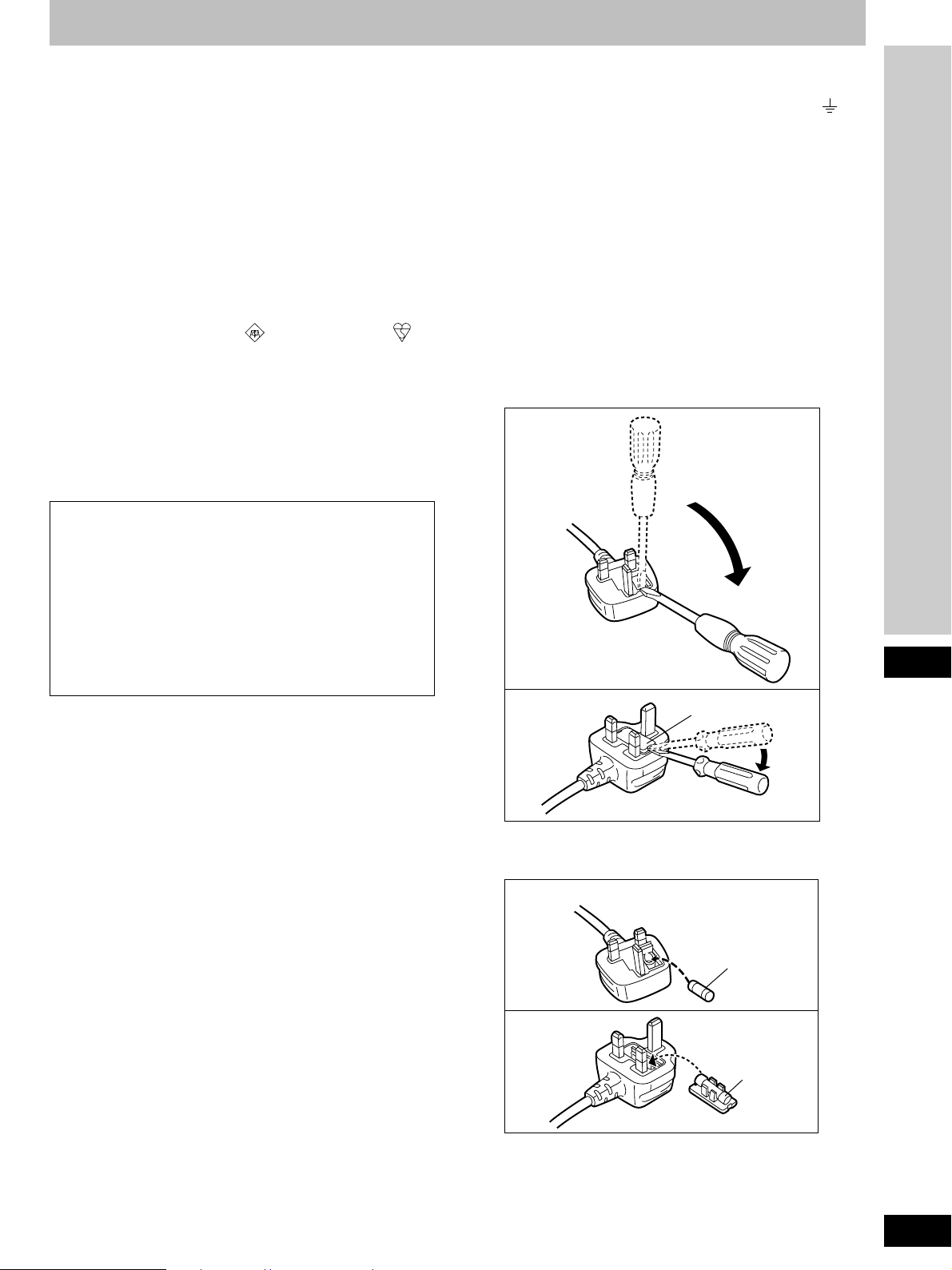
How to replace the fuse
The location of the fuse differ according to the type of
AC mains plug (figures A and B). Confirm the AC
mains plug fitted and follow the instructions below.
Illustrations may differ from actual AC mains plug.
1. Open the fuse cover with a screwdriver.
Figure A
Figure B
Fuse cover
Before use
IMPORTANT
The wires in this mains lead are coloured in
accordance with the following code:
Blue: Neutral, Brown: Live.
As these colours may not correspond with the
coloured markings identifying the terminals in your
plug, proceed as follows:
The wire which is coloured Blue must be connected to
the terminal which is marked with the letter N or
coloured Black or Blue.
The wire which is coloured Brown must be connected
to the terminal which is marked with the letter L or
coloured Brown or Red.
2. Replace the fuse and close or attach the fuse
cover.
Figure A
Fuse
(5 ampere)
Figure B
Fuse
(5 ampere)
3
RQT5518
Page 4
Safety precautions
Placement
Set the unit up on an even surface away from direct sunlight, high
temperatures, high humidity, and excessive vibration. These
conditions can damage the cabinet and other components,
thereby shortening the unit’s service life.
Place it at least 15 cm away from wall surfaces to avoid distortion
and unwanted acoustical effects.
Do not place heavy items on the unit.
Voltage
Do not use high voltage power sources. This can overload the unit
and cause a fire.
Do not use a DC power source. Check the source carefully when
setting the unit up on a ship or other place where DC is used.
AC mains lead protection
Ensure the AC mains lead is connected correctly and not
damaged. Poor connection and lead damage can cause fire or
electric shock. Do not pull, bend, or place heavy items on the lead.
Grasp the plug firmly when unplugging the lead. Pulling the AC
mains lead can cause electric shock.
Do not handle the plug with wet hands. This can cause electric
shock.
CAUTION!
DO NOT INSTALL OR PLACE THIS UNIT IN A BOOKCASE,
BUILT IN CABINET OR IN ANOTHER CONFINED SPACE.
ENSURE THE UNIT IS WELL VENTILATED. ENSURE THAT
CURTAINS AND ANY OTHER MATERIALS DO NOT
OBSTRUCT THE VENTILATION TO PREVENT RISK OF
ELECTRIC SHOCK OR FIRE HAZARD DUE TO
OVERHEATING.
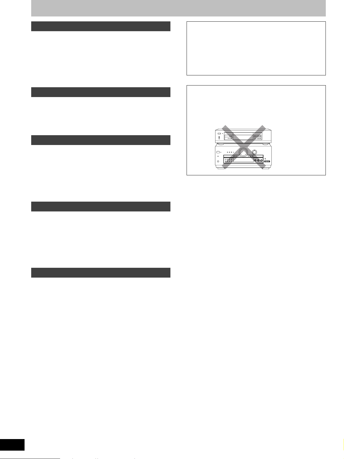
CAUTION
Do not place anything on top of this unit or block the heat
radiation vents in any way. In particular, do not place tape
decks or CD/DVD players on this unit as heat radiated from it
can damage your software.
NO
Foreign matter
Do not let metal objects fall inside the unit. This can cause electric
shock or malfunction.
Do not let liquids get into the unit. This can cause electric shock or
malfunction. If this occurs, immediately disconnect the unit from
the power supply and contact your dealer.
Do not spray insecticides onto or into the unit. They contain
flammable gases which can ignite if sprayed into the unit.
Service
Do not attempt to repair this unit by yourself. If sound is
interrupted, indicators fail to light, smoke appears, or any other
problem that is not covered in these instructions occurs,
disconnect the AC mains lead and contact your dealer or an
authorized service center. Electric shock or damage to the unit
can occur if the unit is repaired, disassembled or reconstructed by
unqualified persons.
Extend operating life by disconnecting the unit from the power
source if it is not to be used for a long time.
4
RQT5518
Page 5
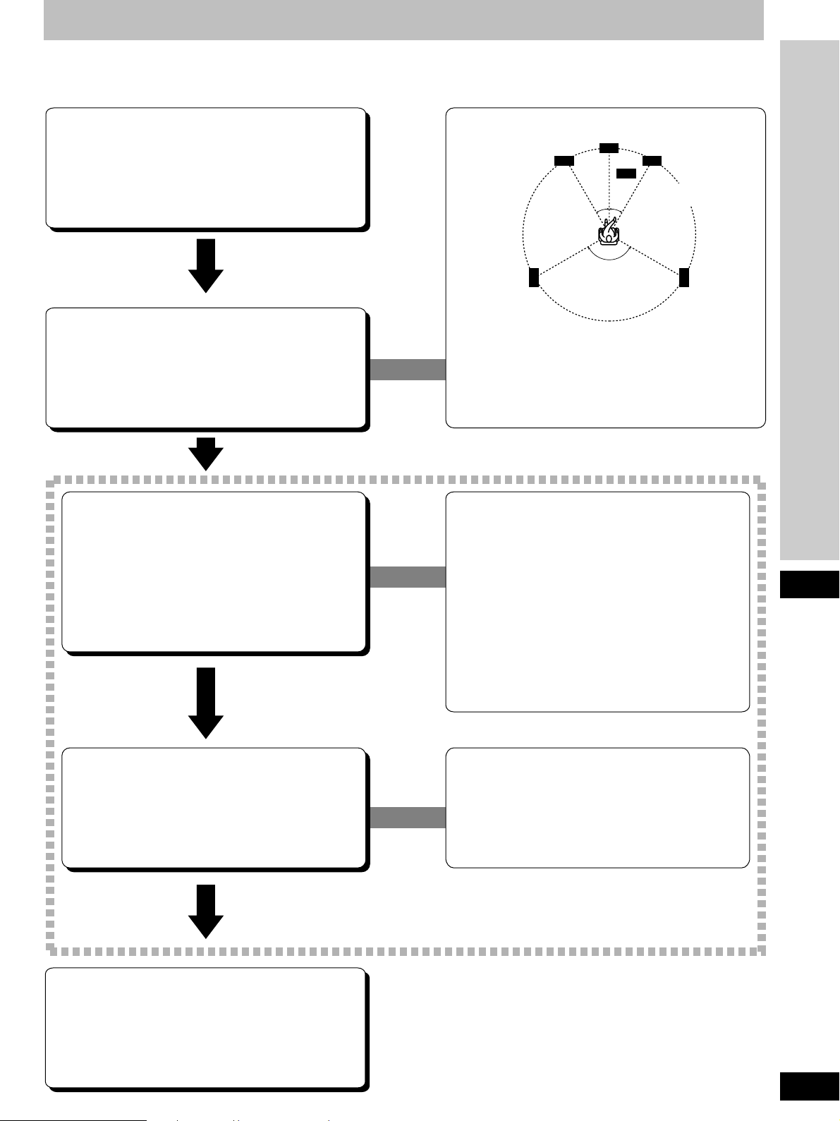
To enjoy surround sound
Do the connections, settings, and adjustments in the order shown to enjoy surround sound.
Be sure to make the correct speaker settings. If, for example, you have not connected a center speaker and you leave the initial setting value
of LARGE as it is, then dialog and other sounds may not be reproduced.
Center speaker
(not included)
30° 30°
30° 30°
120°
Front speaker
(right)
(not included)
Subwoofer
(not included)
Connect the equipment
(a Pages 10–13.)
Front speaker
(left)
(not included)
Position and connect the
speakers
(a Pages 14–16.)
Set the presence and type
(small/large), distance and
filter of the speakers you
have connected
(a Pages 17–18.)
Surround speaker
(left)
(not included)
The front, center, and surround speakers should be placed
at approximately the same distance from the listening
position. The angles in the diagram are approximate.
In SIZE
Select LARGE or SMALL for the front speakers
Select LARGE, SMALL, or NONE for the center and
surround speakers
Select YES or NO for the subwoofer
In DISTANCE
Enter the distance of the front, center, and surround
speakers from the listening position
In FILTER
Enter the cutoff frequency for your subwoofer based on
the bass capability of your front speakers
120°
Surround speaker
(right)
(not included)
Before use
Adjust the level for the
speakers
(a Page 19.)
Sit back and enjoy the
experience
(a Pages 22–23.)
While sitting in the usual listening position, use the test
signal to adjust the volume of the speakers to the same
apparent level.
When using DVD 6CH INPUT mode
These settings need to be changed on the player.
Read the player’s instructions for setting details.
5
RQT5518
Page 6
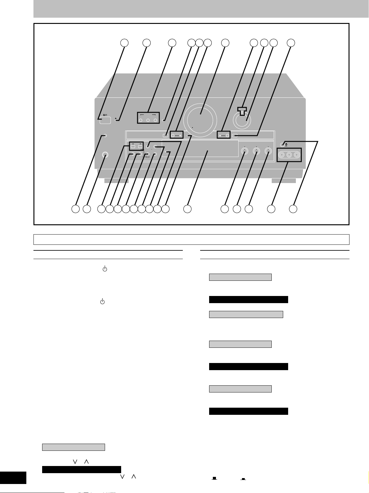
Front panel controls
TIMER
-MODE
–TIME
PHONES
SPEAKERS
A B BI-WIRE BI-AMP
TUNING PRESET MEMORY
PTY SELECTOR
DISPLAY MODE PTY SEARCH
BAND
FM MODE
RDSEON
DSP SOUND MODE
DVD 6CH INPUT
WAKE
32 4
MIN MAX
VGCA
VIA TONE
ON
5 6
71 8 9 10 11
VOLUME
TAPE MONITOR DIGITAL INPUT
DIGITAL
INPUT SELECTOR
BALANCETREBLEBASS
MIN MAX MIN MAX L R
VIDEO IN
VCR 2
VCR 3
VCR 3
L AUDIO IN R
1312 1514 16 17 18 20 2119 22 23 24 25 26 27 28
6
RQT5518
Main unit
No. Name Ref.page
qq
q Standby/on switch ( /l) .................................. 17
qq
Press to switch the unit from on to standby mode or vice
versa.
In standby mode, the unit is still consuming a small amount of
power.
ww
w Standby indicator ( )
ww
When the unit is connected to the AC mains supply, this
indicator lights up in standby mode and goes out when the unit
is turned on.
ee
e Speaker select buttons
ee
(SPEAKERS, A, B, BI-WIRE) ......................17, 22
rr
r Bi-amp indicator (BI-AMP) ............................... 24
rr
tt
t DVD 6CH input select button
tt
(DVD 6CH INPUT).............................................. 26
yy
y VGCA mode select button/indicator
yy
(VGCA, ON)........................................................ 27
uu
u Volume control (VOLUME)............................... 23
uu
ii
i Tape monitor button/indicator
ii
(TAPE MONITOR).............................................. 24
oo
o Digital input indicator (DIGITAL)..................... 22
oo
!0!0
!0 Input selector (INPUT SELECTOR) ...........17, 22
!0!0
!1!1
!1 Digital input select button
!1!1
(DIGITAL INPUT) ............................................... 22
!2!2
!2 Timer button (TIMER, -MODE, –TIME) ............ 49
!2!2
!3!3
!3 Headphones jack (PHONES) ...........................36
!3!3
!4!4
!4 For the United Kingdom
!4!4
Tuning/PTY select buttons
(TUNING, , , PTY SELECTOR) ........... 28, 33
For Australia and New Zealand
Tuning buttons (TUNING, , ) ................... 28
No. Name Ref.page
!5!5
!5 Band select button (BAND) .............................28
!5!5
!6!6
!6 For the United Kingdom
!6!6
FM mode select/EON button
(FM MODE, EON)......................................... 28, 34
For Australia and New Zealand
FM mode select button (FM MODE) ................ 28
!7!7
!7 Only for the United Kingdom
!7!7
RDS button (RDS) .............................................32
!8!8
!8 DSP sound mode select button
!8!8
(DSP SOUND MODE) ........................................ 22
!9!9
!9 For the United Kingdom
!9!9
Memory/PTY search button
(MEMORY, PTY SEARCH) .......................... 30, 33
For Australia and New Zealand
Memory button (MEMORY) .............................. 30
@0@0
@0 Wake indicator (WAKE).................................... 49
@0@0
@1@1
@1 For the United Kingdom
@1@1
Preset channel/Display mode select button
(PRESET, DISPLAY MODE) ....................... 31, 32
For Australia and New Zealand
Preset channel button (PRESET) .................... 31
@2@2
@2 Via tone indicator (VIA TONE)......................... 27
@2@2
@3@3
@3 Display section ................................................... 7
@3@3
@4@4
@4 Bass control (BASS)......................................... 25
@4@4
@5@5
@5 Treble control (TREBLE).................................. 25
@5@5
@6@6
@6 Balance control (BALANCE)............................25
@6@6
@7@7
@7 VCR 3 terminals (VCR 3) .................................. 11
@7@7
@8@8
@8 VCR 2/VCR 3 select button
@8@8
( VCR 2, VCR 3) .......................................... 25
Page 7
29 30 32 33 34 35 36 3831 37 39 40 41
TUNED STEREO
WAKE
MONO
LOW IMP
SPEAKERS
AB
BI-WIRE
SUBWOOFER
DIGITAL
EONPS PTY RT
SLEEP
PRO LOGIC
kHz
MHz
AAC
MRDS
PROGRAM FORMAT
LCR
LS S LFE RS
SOUND MODE
STEREO
SURROUND
SFC
4342 44 45 46
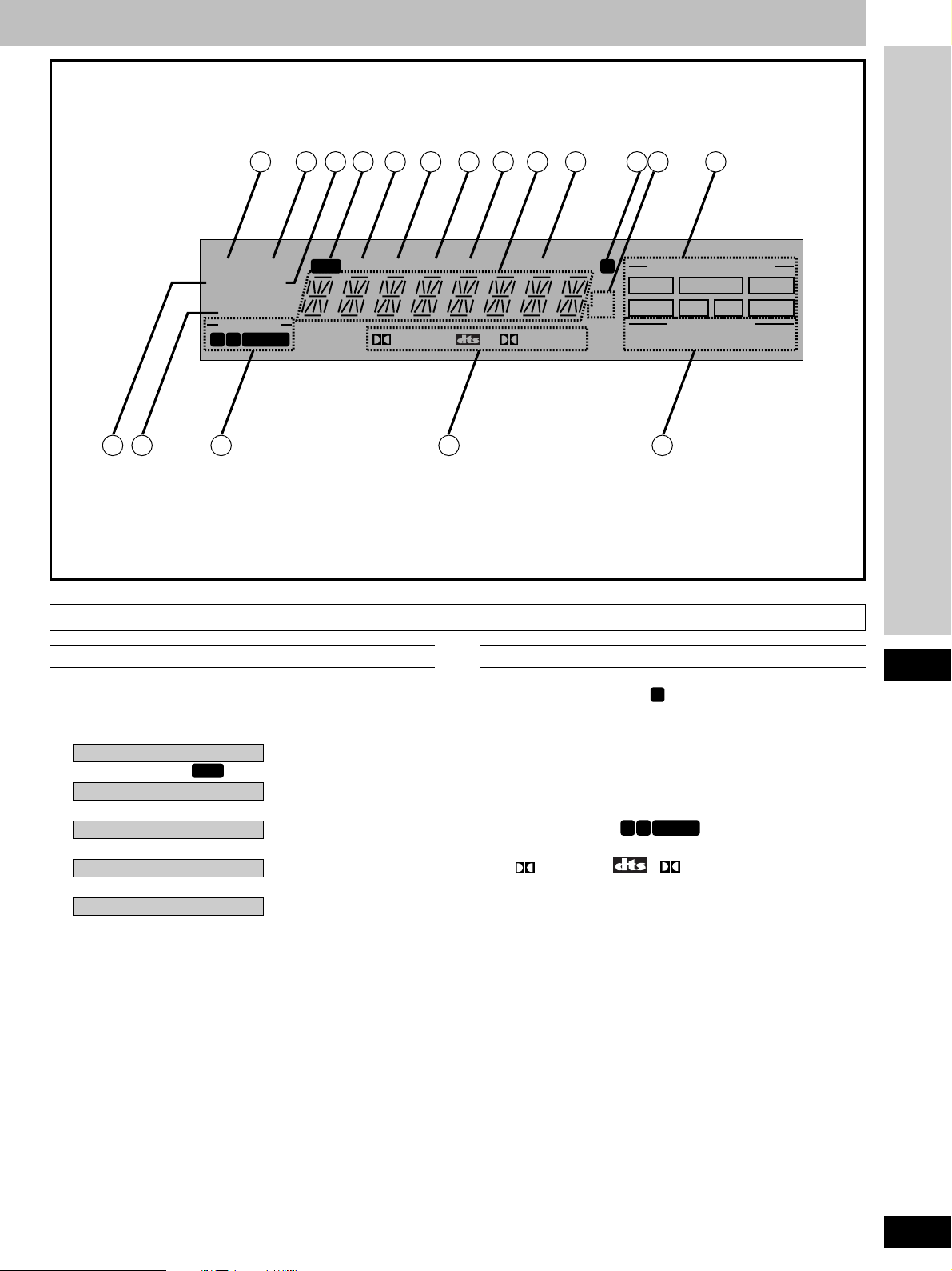
Display section
No. Name Ref.page No. Name Ref.page
@9@9
@9 Tuned indicator (TUNED).................................28
@9@9
#0#0
#0 Stereo indicator (STEREO) .............................. 28
#0#0
#1#1
#1 Monaural indicator (MONO)............................. 28
#1#1
#2#2
#2 Only for the United Kingdom
#2#2
RDS indicator (
#3#3
#3 Only for the United Kingdom
#3#3
RDS
) ........................................32
PS indicator (PS)............................................... 32
#4#4
#4 Only for the United Kingdom
#4#4
PTY indicator (PTY) .......................................... 32
#5#5
#5 Only for the United Kingdom
#5#5
RT indicator (RT)............................................... 32
#6#6
#6 Only for the United Kingdom
#6#6
EON indicator (EON)......................................... 34
#7#7
#7 Display
#7#7
#8#8
#8 Sleep indicator (SLEEP)...................................49
#8#8
#9#9
#9 Memory indicator (M)...................................... 30
#9#9
$0$0
$0 Frequency unit indicator (kHz, MHz) .............. 28
$0$0
$1$1
$1 Program format indicators
$1$1
(PROGRAM FORMAT, L, C, R, LS, S, LFE, RS)......
$2$2
$2 Wake indicator (WAKE).................................... 49
$2$2
$3$3
$3 Low impedance indicator (LOW IMP) ............. 24
$3$3
$4$4
$4 Front speaker indicator
$4$4
AB
(-SPEAKERS-,
$5$5
$5 Signal format indicators
$5$5
BI-WIRE
).............................. 22
20
( DIGITAL, , PRO LOGIC) ..............20
$6$6
$6 DSP sound mode indicators
$6$6
(SOUND MODE, STEREO, SURROUND, SFC) .......
20
Before use
7
RQT5518
Page 8
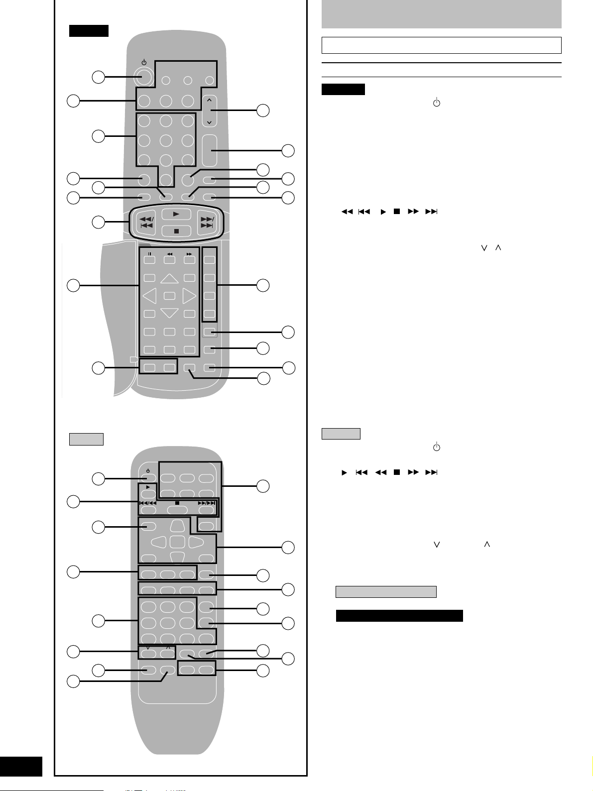
SA-DA10
Front panel controls
Remote control
48
50
51
53
47
49
48
52
54
TV VCR
TAPE CD
1
23
4
56
7089
DIRECT TUNING/
DISC ENTER
DISC/DECK 1/2MDSOUND MODE
DVD
TOP MENU
DISPLAY RETURN
SUB TITLE
GROUP
SLOW/
SEARCH
ENTER
AUDIO ANGLE
–+
PAGE
TV VOL TV/AV
–+
TUNER/BAND
VOLUME
≥10/ENTER
MUTING
-/--
DELAY
LEVEL
MENU
DIMMER
DVD 6CH
DVD
CH
+
–
SFC
+
–
TEST
55
57
59
61
63
65
56
58
60
62
64
No. Name Ref.page
SA-DA10
$7$7
$7 Standby/on button ( ) .................................... 39
$7$7
$8$8
$8 Input select buttons
$8$8
(TV, VCR, DVD, TAPE, CD, TUNER/BAND, MD) .....
$9$9
$9 Numbered buttons...................................... 29, 39
$9$9
%0%0
%0 Direct tuning/disc enter button
%0%0
39
(DIRECT TUNING/DISC ENTER) ................ 29, 39
%1%1
%1 Disc/deck 1/2 select button
%1%1
(DISC/DECK 1/2)................................................ 41
%2%2
%2 Disc and deck operation buttons
%2%2
( / , , , / )...................................... 41
%3%3
%3 DVD player operation buttons......................... 45
%3%3
%4%4
%4 TV volume buttons (–TV VOL+)....................... 43
%4%4
%5%5
%5 Channel up/down button (CH, , )............... 39
%5%5
%6%6
%6 Volume buttons (VOLUME, +, –) .............. 19, 39
%6%6
%7%7
%7 ≥10/ENTER, -/– – button
%7%7
(≥10/ENTER, -/– –)............................................. 39
%8%8
%8 Muting button (MUTING) ............................ 37, 39
%8%8
%9%9
%9 DSP sound mode select button
%9%9
(SOUND MODE)................................................. 39
^0^0
^0 SFC mode select button (SFC).................. 23, 39
^0^0
^1^1
^1 Delay time/level adjust buttons
^1^1
(DELAY, LEVEL, +, –) ...........................19, 23, 39
^2^2
^2 Test button (TEST)......................................19, 39
^2^2
^3^3
^3 Dimmer button (DIMMER) .......................... 37, 39
^3^3
^4^4
^4 DVD 6CH input select button
^4^4
(DVD 6CH).......................................................... 39
^5^5
^5 TV/AV select button (TV/AV)............................43
^5^5
8
RQT5518
SA-DA8
67
69
71
73
66
68
70
72
TV VCR
TAPE MD CD
TOP MENU
DISC/DECK
ENTER
1/2
DISPLAY
STEREO
SURROUND
SFC TEST
DELAY
LEVEL
123
456
7
890
TV VOL
TV/AV
DIMMER VOL
MUTING
TUNER/
BAND
DVD
MENU
+–
DIRECT TUNING/
DISC ENTER
≥10/–/– –
DVD 6CH
+–
74
76
78
80
82
75
77
79
81
SA-DA8
^6^6
^6 Standby/on button ( ) .................................... 39
^6^6
^7^7
^7 Disc and deck operation buttons
^7^7
( , / , , / )...................................... 41
^8^8
^8 Disc/deck 1/2 select button
^8^8
(DISC/DECK 1/2)................................................ 41
^9^9
^9 DSP sound mode and SFC mode select
^9^9
buttons (STEREO, SURROUND, SFC) ......23, 39
&0&0
&0 Numbered buttons...................................... 29, 39
&0&0
&1&1
&1 TV volume buttons ( TV VOL )................... 43
&1&1
&2&2
&2 Dimmer button (DIMMER)...........................37, 39
&2&2
&3&3
&3 Muting button (MUTING) ............................ 37, 39
&3&3
&4&4
&4 Input select buttons
&4&4
For the United Kingdom
(TV, VCR, TUNER/BAND, TAPE, MD, CD, DVD) .....
For Australia and New Zealand
39
(TV, VCR, TUNER/BAND, TAPE, CD, DVD)..... 39
&5&5
&5 DVD player operation buttons......................... 45
&5&5
&6&6
&6 Test button (TEST)......................................19, 39
&6&6
&7&7
&7 Delay time/level adjust buttons
&7&7
(DELAY, LEVEL, –, +) ...........................19, 23, 39
&8&8
&8 Direct tuning/disc enter button
&8&8
(DIRECT TUNING/DISC ENTER) ................ 29, 39
&9&9
&9 ≥10/-/– – button (≥10/-/– –)................................39
&9&9
*0*0
*0 DVD 6CH input select button
*0*0
(DVD 6CH).......................................................... 39
*1*1
*1 TV/AV select button (TV/AV)............................43
*1*1
*2*2
*2 Volume buttons (– VOL +) .......................... 19, 39
*2*2
Page 9
A
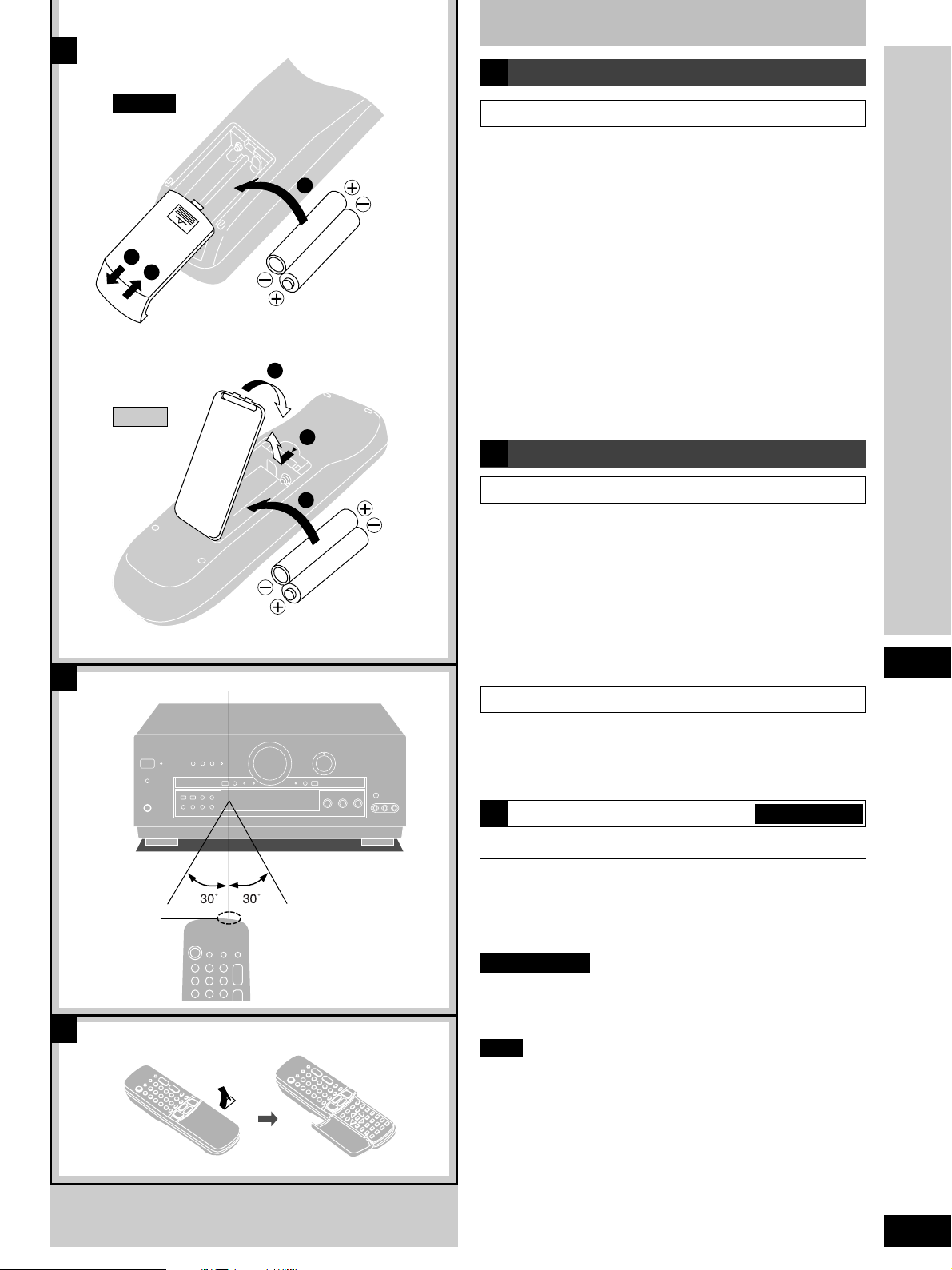
Concerning the remote control
A
Battery installation
B
SA-DA10
1
3
SA-DA8
Remote control signal sensor
Use of batteries
¡Align the poles (+ and –) properly when inserting the batteries.
Press in and down towards the minus end.
2
(R6, AA, UM-3)
3
1
2
(R6, AA, UM-3)
¡Do not mix old and new batteries or different types of batteries.
¡Do not recharge ordinary dry cell batteries.
¡Do not heat or disassemble the batteries. Do not allow them to
contact flame or water.
¡Remove the batteries if the unit is not to be used for a long time.
¡Do not keep together with metallic objects such as necklaces.
¡Do not use rechargeable type batteries.
¡Do not use batteries if the covering has been peeled off.
Mishandling of batteries can cause electrolyte leakage which can
damage items the fluid contacts and may cause a fire.
If electrolyte leaks from the batteries, consult your dealer.
Wash thoroughly with water if electrolyte comes in contact with
any part of your body.
B
Correct method of use
Operation notes
¡Do not place obstacles between the remote control signal
sensor and remote control unit.
¡Do not expose the remote control signal sensor to direct
sunlight or to the bright light of a fluorescent light.
¡Take care to keep the remote control signal sensor and end of
the remote control unit free from dust.
¡If the unit is installed in a rack with glass doors, the glass doors’
thickness or color might make it necessary to use the remote
control a shorter distance from the unit.
Before use
To prevent damage
Transmission
window
C
About 7 meters in front of the
signal sensor. (The actual
range will depend on the
angle at which the remote
control is used.)
¡Never place heavy items on top of the unit.
¡Do not disassemble or reconstruct the unit.
¡Do not spill water or other liquids into the unit.
How to open the remote control SA-DA10 only
C
For your reference
This remote control can be used to operate the receiver you
purchased and some other Panasonic and Technics cassette
decks, MD decks, CD players, TVs, VCRs and DVD players,
provided they are equipped with a remote control sensor.
SA-DA10 only
It is also possible to change-over the remote control code so that
the remote control can operate TVs, VCRs and DVD players which
have not been manufactured by this company (a pages 46–47).
Note
¡For details on operating other equipment, see the instruction
manual provided with specific unit.
¡Some models cannot be operated by this remote control.
¡Actual operations depend on your equipment and software.
9
RQT5518
Page 10
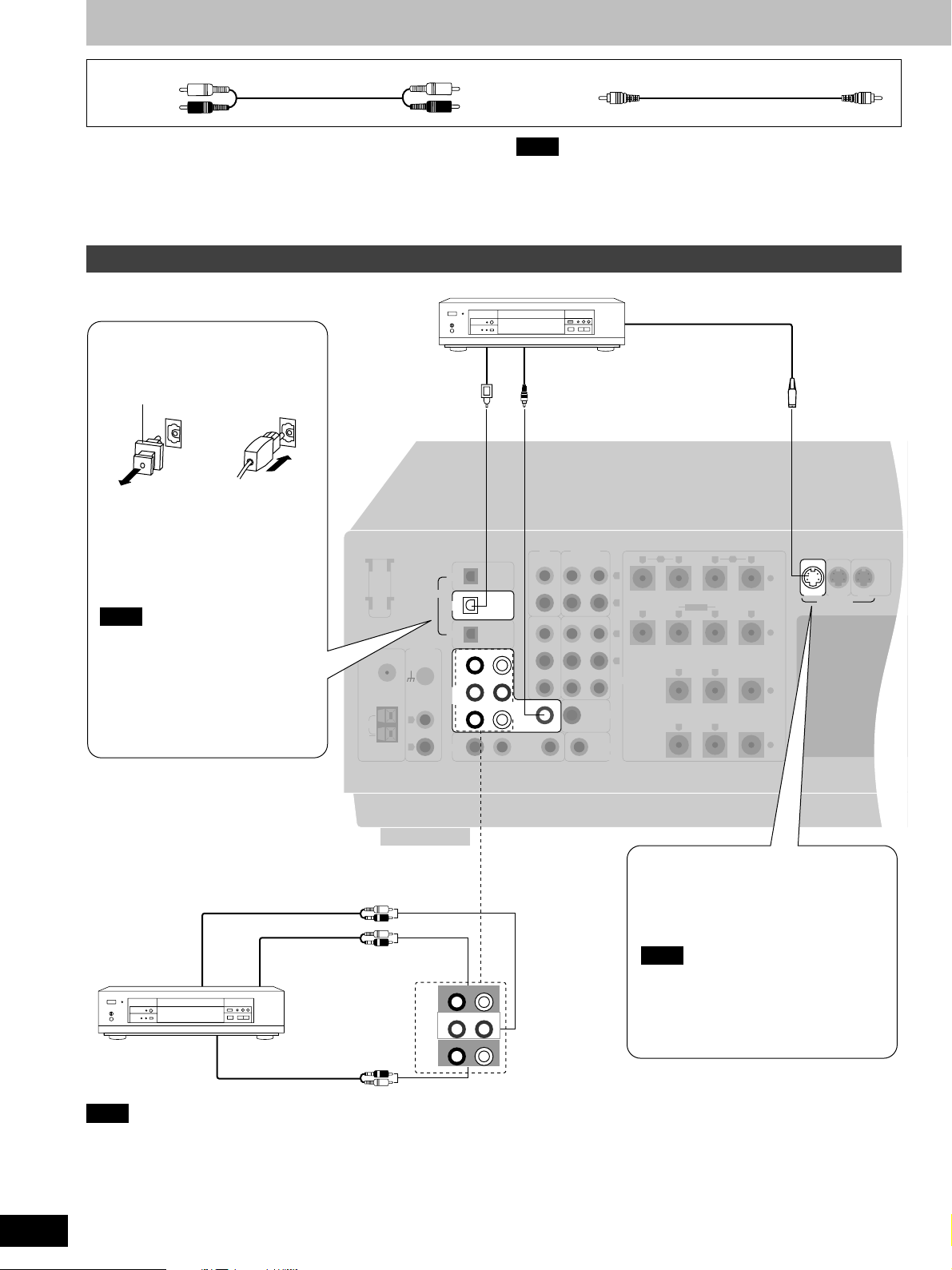
Connections
Stereo phono cable (not included)
White (L)
Red (R)
Turn off all components before making any connections.
To connect equipment, refer to the appropriate operating
instructions.
Connecting a DVD player
Optical fiber cable
connection
Dust cap
¡Do not bend the optical fiber cable.
¡If the digital optical connector is not
going to be used, be sure to attach
the dust cap to prevent exposure to
dust.
Note
Dolby Digital RF (radio frequency)
signals cannot be decoded with this
unit.
FM
ANT
75 Ω
LOOP
EXT
AM
ANT
LOOP ANT
HOLDER
DIGITAL
PHONO
GND
L
R
Note
¡Use digital connection to enjoy Dolby Digital or DTS
(\ page 20).
¡Use analogue connection to enjoy sources that cannot be
decoded on this unit and to record a source (a pages 22 and
48).
DVD player (not included)
VIDEO OUTDIGITAL OUT
OPTICAL
CD
OPTICAL
DVD
OPTICAL
TV
FRONT
RL
SUBWOOFERINCENTER
DVD/
DVD 6CH
SURROUNDRSURROUND
TV
RLIN IN
CD TAPE/MD
VCR 2 VCR 1
IN
IN
L
IN
Video connection cable (not included)
S-VIDEO OUT
FRONT
BI-WIRE
SURROUND
A
+
–
CENTER
+
–
B
RLRL
LF HF
RLRL
RL
RL
OUT
OUT
(OUT)
REC
PLAY
(IN)
IN
IN
SUBWOOFER
OUT
TV
MONITOR OUT
L
R
L
R
SPEAKERS
IN
DVD
IN
VCR 1 TV
S-VIDEO
MONITOR
OUT
10
RQT5518
To connect analogue 6 channel
AUDIO OUT
(CENTER)
(SUBWOOFER)
AUDIO OUT
(SURROUND L,R)
Note
Connect to FRONT L, R if your DVD player does not have 6 channel output.
AUDIO OUT
(FRONT L,R)
FRONT
RL
SUBWOOFERINCENTER
DVD/
DVD 6CH
SURROUNDRSURROUND
L
The S-VIDEO terminals
Connections through these terminals
provide higher quality pictures than
through the video terminal.
Note
When using S-VIDEO terminals, be
aware that video signals input into the
VIDEO terminals cannot be output from
S-VIDEO terminals or vice versa.
Page 11
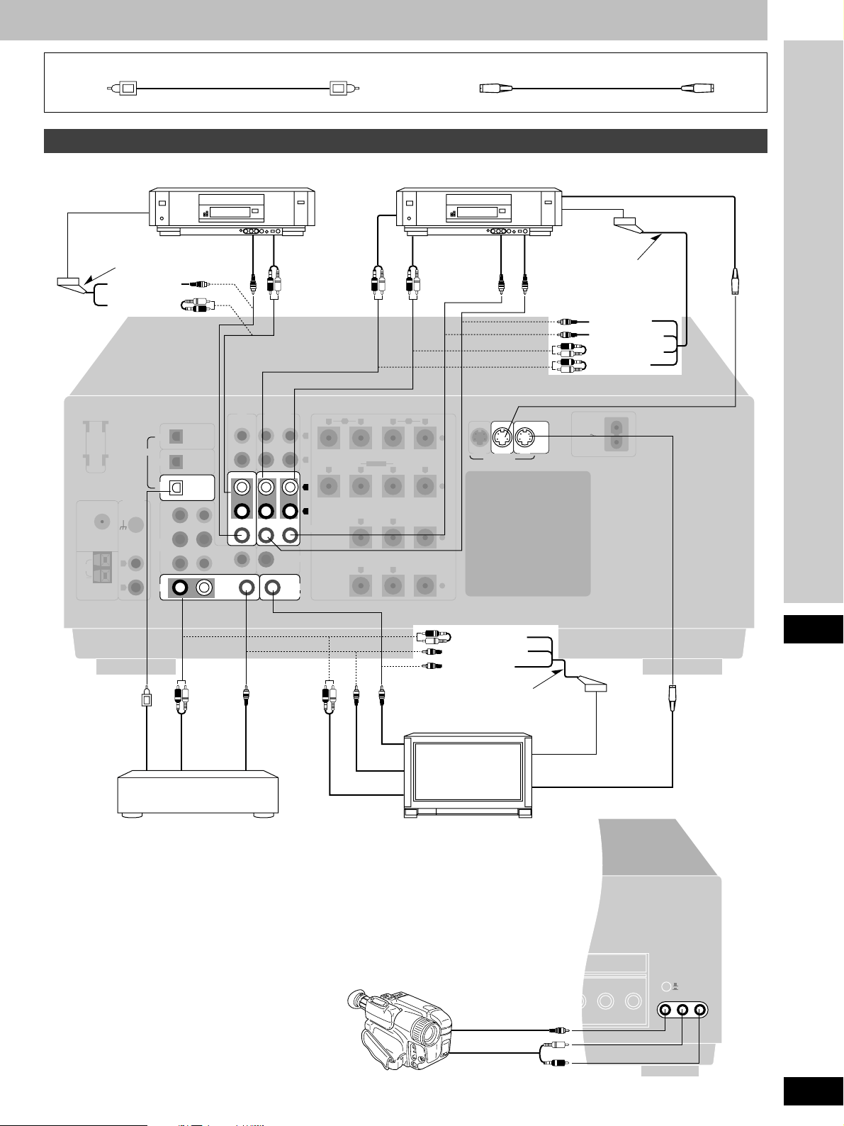
Optical fiber cable (not included)
Connecting video equipment
S-VIDEO cable (not included)
VCR (for play only) (not included)
AV IN
21pin scart cable
(not included)
(VIDEO OUT)
(AUDIO OUT)
LOOP ANT
HOLDER
DIGITAL
FM
ANT
75 Ω
LOOP
EXT
AM
ANT
PHONO
GND
DVD 6CH
L
R
OPTICAL
CD
OPTICAL
DVD
OPTICAL
TV
FRONT
RL
SUBWOOFERINCENTER
DVD/
SURROUNDRSURROUND
TV
RLIN IN
VIDEO
OUT
VCR 2 VCR 1
IN
IN
L
IN
or
CD TAPE/MD
REC
(OUT)
OUT
OUT
SUBWOOFER
OUT
MONITOR OUT
AUDIO
OUT
PLAY
(IN)
L
R
L
IN
R
IN
SPEAKERS
TV
VCR (not included)
AUDIO
IN
AUDIO
OUT
or
FRONT
B
RLRL
LF HF
RLRL
SURROUND
RL
RL
A
+
BI-WIRE
–
CENTER
+
–
VIDEO
OUT
IN
DVD
IN
VCR 1
S-VIDEO
VIDEO
IN
MONITOR
OUT
TV
S-VIDEO OUT
AV IN
21pin scart cable
(not included)
(VIDEO IN)
(VIDEO OUT)
(AUDIO OUT)
(AUDIO IN)
AC IN
Connections
DIGITAL
OUT
AUDIO
OUT
Satellite receiver, etc.
(not included)
Connecting to the VCR 3 terminals on the front panel
or
VIDEO
OUT
VIDEO
IN
VIDEO OUT
AUDIO OUT
(AUDIO OUT)
(VIDEO OUT)
(VIDEO IN)
21pin scart cable
(not included)
TV or TV monitor
(not included)
VIDEO
OUT
AV IN
S-VIDEO IN
VIDEO IN
VCR 2
VCR 3
VCR 3
L AUDIO IN R
Video camera, etc.
(not included)
AUDIO
OUT
11
RQT5518
Page 12
LOOP ANT
HOLDER
FM
ANT
75 Ω
EXT
AM
ANT
GND
OPTICAL
OPTICAL
OPTICAL
FRONT
RL
SUBWOOFERINCENTER
SURROUNDRSURROUND
L
RLIN
IN
IN
IN
IN
IN
IN
OUT
OUT
VCR 2 VCR 1
REC
(OUT)
PLAY
(IN)
FRONT
SURROUND
CENTER
LF HF
+
–
+
–
A
BI-WIRE
DIGITAL
CD
DVD
TV
DVD/
DVD 6CH
TV
LOOP
MONITOR OUT
TV
SUBWOOFER
OUT
CD TAPE/MD
SPEAKERS
PHONO
L
R
R
L
R
L
RLRL
RLRL
RL
RL
B
OUTPUT
OUTPUT GND
REC (IN) PLAY (OUT)
DIGITAL OUT
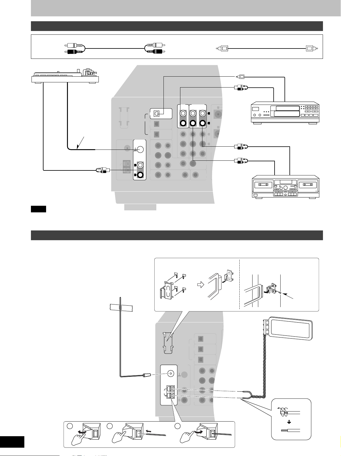
Connections
Connecting audio equipment
Stereo phono cable (not included)
Optical fiber cable (not included)
White (L)
Red (R)
Turntable (not included)
Only for
turntable with
ground
terminal.
CD player (or CD changer)
(not included)
Tape deck or MD deck (not included)
Note
If you want to connect a graphic equalizer, connect it to the TAPE/MD (for the United Kingdom) or TAPE (for Australia and New Zealand)
terminals (\ page 24).
Antenna connections
AM loop antenna
¡ Fit the AM loop antenna holder (included) onto the rear
panel of this unit and then attach the AM loop antenna
to the AM loop antenna holder (facing in the direction
of best reception).
¡ Keep the antenna cord away from tape decks, DVD
players, and other cords.
FM indoor antenna
(included)
FM antenna
Fix the other end of the antenna where
reception is best.
1 2 3
Adhesive tape
(not included)
LOOP ANT
HOLDER
FM
ANT
75 Ω
LOOP
EXT
AM
ANT
OPTICAL
CD
OPTICAL
DIGITAL
DVD
PHONO
GND
L
R
OPTICAL
TV
RL
SUBWOOFERINCENTER
DVD/
DVD 6CH
SURROUNDRSURROUND
TV
RLIN
FRONT
When mounting the antenna
to a column, wall or rack
CD TAPE
REC
PLAY
(OUT)
(IN)
IN
IN
SUBWOOFER
OUT
TV
MONITOR OUT
L
R
L
R
VCR 2 VCR 1
IN
OUT
IN
OUT
L
IN
IN
Screw
(included)
AM loop antenna
(included)
12
RQT5518
Page 13
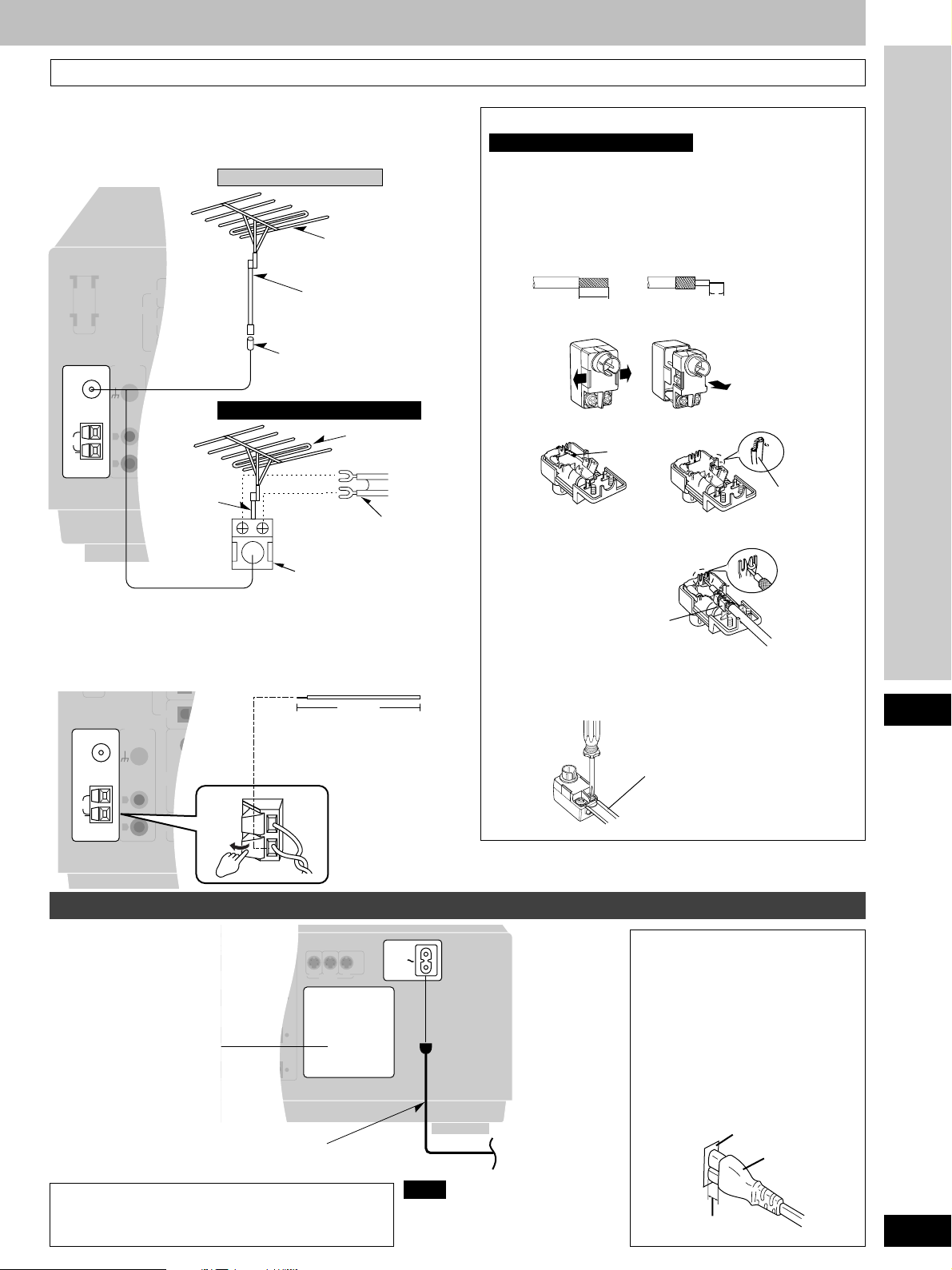
To connect an outdoor antenna
FM outdoor antenna
¡ Disconnect the FM indoor antenna.
¡ The antenna should be installed by a competent technician.
For the United Kingdom
FM outdoor antenna
(not included)
PLAY
(IN)
L
75 Ω coaxial cable
(not included)
R
L
Antenna plug (included)
IN
R
IN
SUBWOOFER
OUT
MONITOR OUT
FM outdoor antenna
(not included)
TV
FM
ANT
75 Ω
LOOP
EXT
AM
ANT
LOOP ANT
HOLDER
DIGITAL
PHONO
GND
L
R
OPTICAL
CD
OPTICAL
DVD
OPTICAL
TV
FRONT
RL
SUBWOOFERINCENTER
DVD/
DVD 6CH
SURROUNDRSURROUND
TV
75 Ω
RLIN
coaxial cable
CD TAPE
REC
(OUT)
VCR 2 VCR 1
IN
OUT
IN
OUT
For Australia and New Zealand
L
IN
IN
(not included)
300 Ω feeder wire
(not included)
Antenna plug (included)
AM outdoor antenna
¡ Run a piece of vinyl wire horizontally across a window or other
convenient location.
¡ Leave the loop antenna connected.
¡ Disconnect the antenna when the unit is not in use. Do not use
the antenna during an electrical storm.
FM
ANT
75 Ω
LOOP
EXT
AM
ANT
PHONO
GND
L
R
OPTICAL
TV
FRONT
RL
SUBWOOFERINCENTER
DVD/
DVD 6CH
SURROUNDRSURROUND
TV
RLIN
IN
IN
L
IN
VCR 2 VCR 1
OUT
OUT
IN
5–12 m
L
IN
Vinyl-covered wire
R
(not included)
IN
SUBWOOFER
OUT
TV
MONITOR OUT
How to use the antenna plug (included)
For Australia and New Zealand
Two types of wire are most commonly used for connection from
the antenna: 300 Ω parallel feeder wire or 75 Ω coaxial cable.
For best resistance to outside interference, the use of 75 Ω
coaxial cable is suggested.
¡¡
¡ To connect a 75 Ω coaxial cable
¡¡
q Remove a piece of the outer vinyl insulator.
a
20 mm 10 mm
w Carefully pull the tabs apart to remove the cover.
e Remove the lead wire and clamp it with the plastic bar.
Lead wire
Plastic bar
r Install the coaxial cable.
Clamp the cable conductor, and wind it on so that it doesn’t
contact anything else.
Press down with pliers.
t Attach the cover.
¡¡
¡ To connect a 300 Ω feeder wire
¡¡
Loosen the screws, connect the wires, and tighten the screws
to secure the connection.
300 Ω feeder wire
(not included)
Connections
Connecting the AC mains lead and other information
FRONT
A
Cooling fan
The cooling fan operates at
high power output levels
only.
LRL
LF HF
BI-WIRE
LRL
SURROUND
RL
RL
CENTER
+
–
+
–
AC mains lead (included)
(FOR THE UNITED KINGDOM ONLY)
READ THE CAUTION FOR THE AC MAINS
LEAD ON PAGE 3 BEFORE CONNECTION.
IN IN
S-VIDEO
MONITOR
OUT
VCR 1 TVDVD
AC IN
Note
The included AC mains lead is for
use with this unit only.
Do not use it with other equipment.
To household mains
socket
AC mains lead
Connect this lead only after all other
cables and cords are connected.
Insertion of Connector
Even when the connector is perfectly
inserted, depending on the type of inlet
used, the front part of the connector
may jut out as shown in the drawing.
However there is no problem using the
unit.
Appliance inlet
Connector
Approx. 6 mm
13
RQT5518
Page 14
LOOP ANT
HOLDER
FM
ANT
75 Ω
EXT
AM
ANT
GND
OPTICAL
OPTICAL
OPTICAL
FRONT
RL
SUBWOOFERINCENTER
SURROUNDRSURROUND
L
RLIN
IN
IN
IN
IN
IN
IN
OUT
OUT
VCR 2 VCR 1
REC
(OUT)
PLAY
(IN)
IN IN
FRONT
SURROUND
CENTER
LF HF
+
–
+
–
AC IN
A
BI-WIRE
DIGITAL
CD
DVD
TV
DVD/
DVD 6CH
TV
LOOP
MONITOR OUT
TV
SUBWOOFER
OUT
CD TAPE/MD
SPEAKERS
VCR 1 TVDVD
S-VIDEO
PHONO
L
R
R
L
R
L
RLRL
RLRL
RL
RL
B
MONITOR
OUT
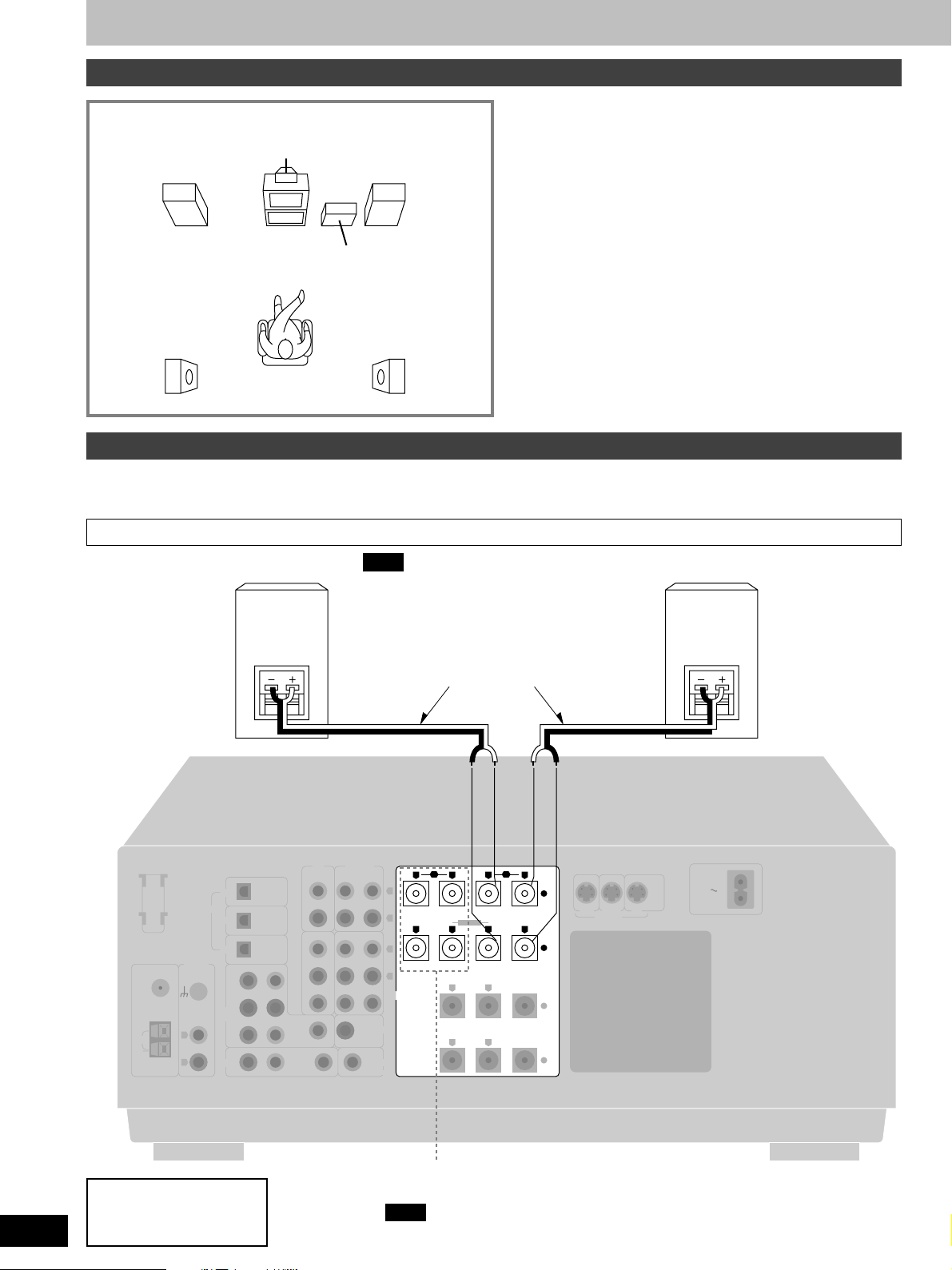
Speaker connections
Placement of speakers
Front speaker
(left)
(not included)
Center speaker
(not included)
Front speaker
(right)
(not included)
Subwoofer
(not included)
Surround speaker
(left)
(not included)
Surround speaker
(right)
(not included)
Connecting speakers
Other connections are possible depending on your speaker system.
See your speaker system’s operating instructions for details.
Front speakers
Note
If you connect speakers with an impedance
Front speaker
(right)
(not included)
under 6 Ω, switch on “LOW IMP” (\ page 24).
Speaker cables
(not included)
Front speakers
Place on the left and right of the TV at seated ear height so that
there is good coherency between the picture and sound.
Center speaker
Place underneath or above the center of the TV. Aim the speaker
at the seating area.
Surround speakers
Place on the side of or slightly behind the listening position, about
one meter higher than ear level.
Subwoofer
The subwoofer can be placed in any position as long as it is at a
reasonable distance from the TV.
Note that some experimentation can yield the smoothest low
frequency performance. Placement near a corner can increase the
apparent output level, but can result in unnatural bass.
Front speaker
(left)
(not included)
14
RQT5518
Speaker impedance:
A or B: 4-16 Ω
A and B: 8-16 Ω
“B” terminals
For connection to a second pair of speakers.
Note
Use the A terminals to enjoy SURROUND, SFC and DVD 6CH INPUT.
Page 15
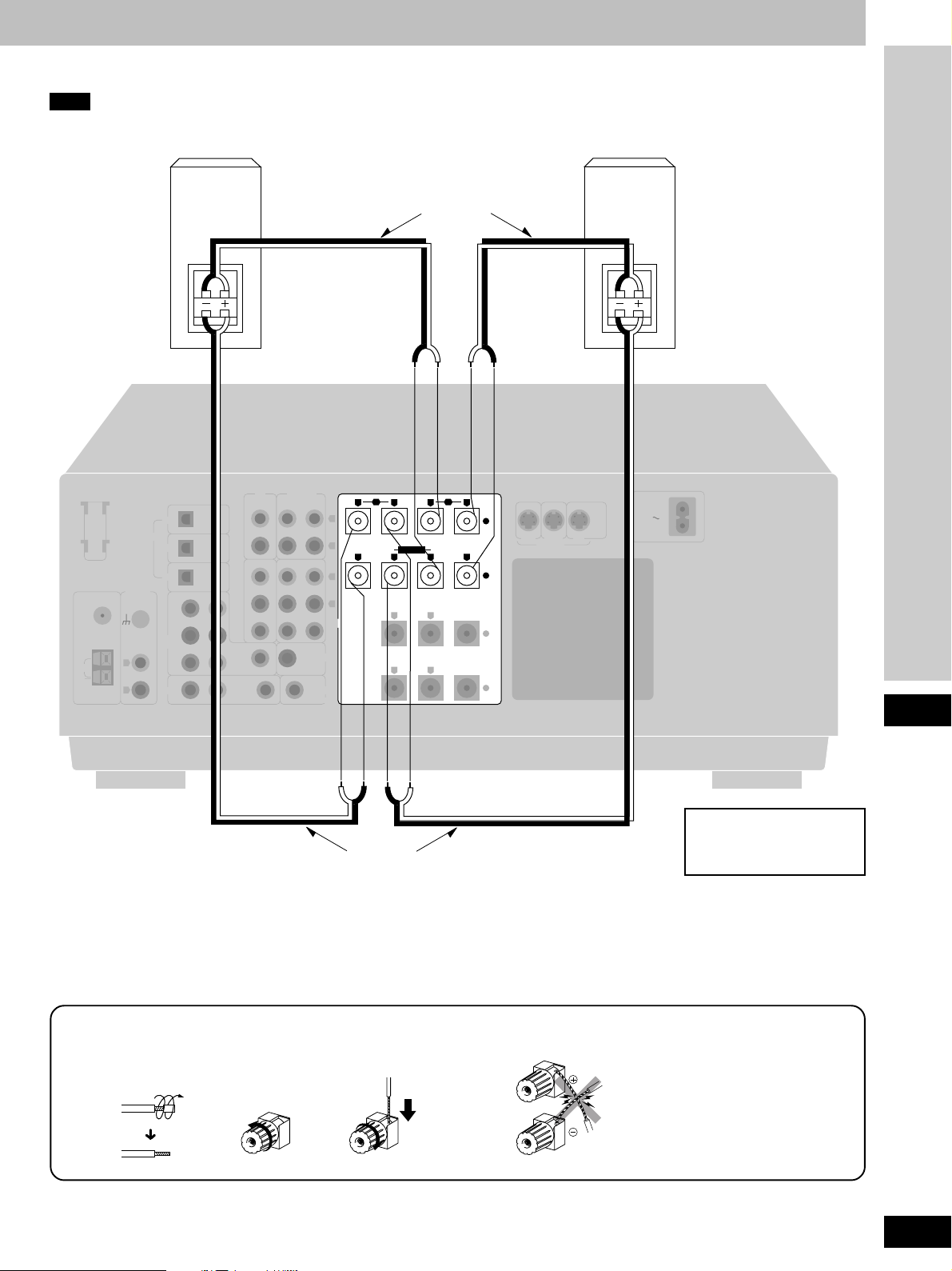
Bi-wiring connection
Note
When bi-wiring, use speakers designed for that purpose that have combined impedance of 6–16 Ω.
Speaker cables
(not included)
Front speaker
(right)
(not included)
Front speaker
(left)
(not included)
FM
ANT
75 Ω
LOOP
EXT
AM
ANT
LOOP ANT
HOLDER
PHONO
GND
L
R
DIGITAL
CD
DVD
TV
DVD/
DVD 6CH
TV
HF
LF
OPTICAL
OPTICAL
OPTICAL
FRONT
RL
SUBWOOFERINCENTER
SURROUNDRSURROUND
RLIN
L
IN
CD TAPE/MD
REC
(OUT)
VCR 2 VCR 1
IN
OUT
IN
OUT
IN
PLAY
(IN) IN IN
L
R
L
IN
R
IN
SPEAKERS
SUBWOOFER
OUT
TV
MONITOR OUT
FRONT
BI-WIRE
SURROUND
A
+
–
CENTER
+
–
B
RLRL
LF HF
RLRL
RL
RL
VCR 1 TVDVD
S-VIDEO
MONITOR
HF
LF
OUT
AC IN
Connections
Connecting the cables
1
2
Speaker cables
(not included)
3
Speaker impedance:
BI-WIRE: 6-16 Ω
NO
15
RQT5518
Page 16
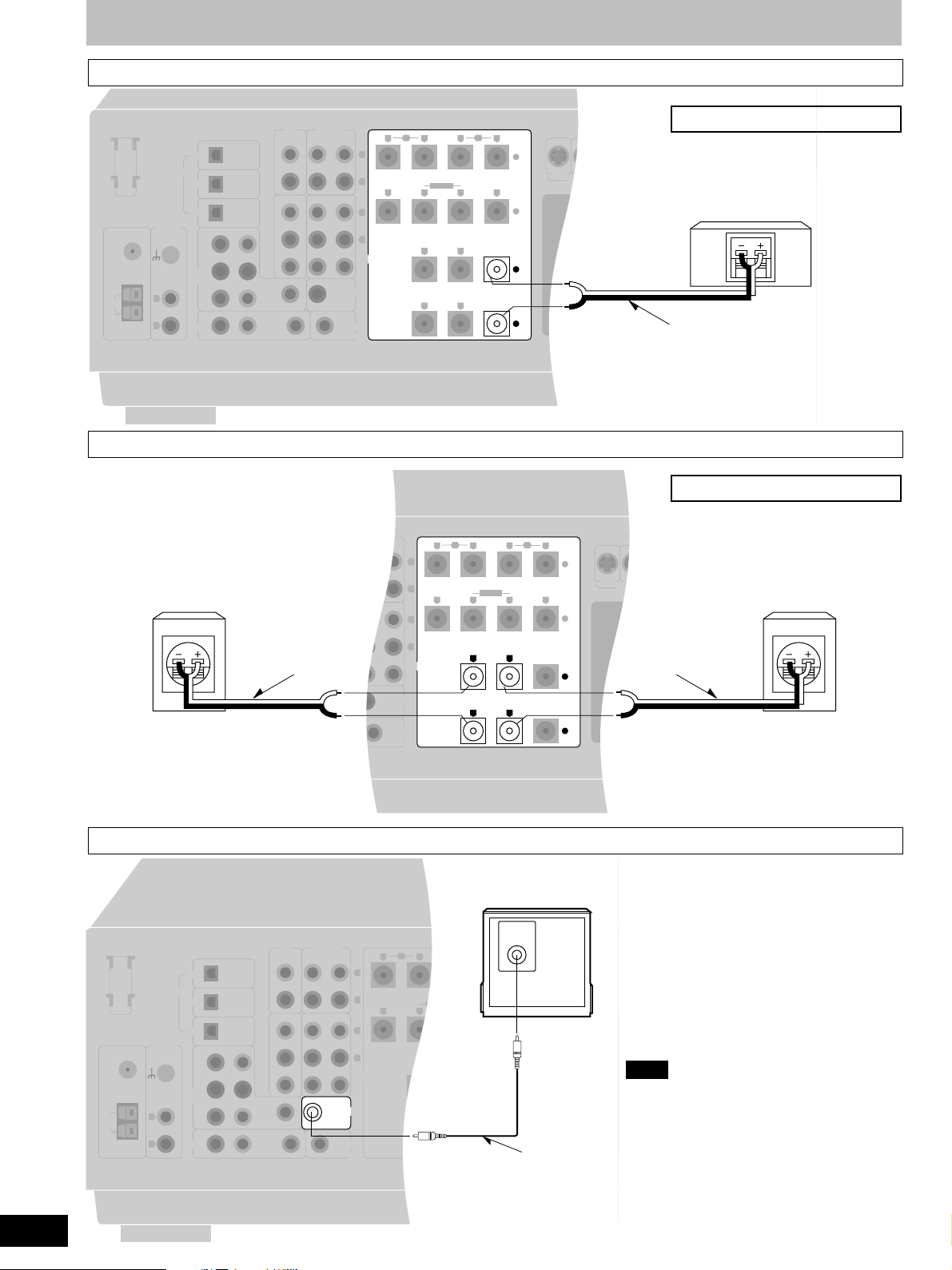
Speaker connections
Center speaker
FM
ANT
75 Ω
LOOP
EXT
AM
ANT
LOOP ANT
HOLDER
PHONO
GND
L
R
DIGITAL
CD
DVD
TV
DVD/
DVD 6CH
TV
Surround speakers
LOOP ANT
HOLDER
Surround speaker (right)
(not included)
FM
ANT
75 Ω
GND
LOOP
EXT
AM
ANT
OPTICAL
OPTICAL
OPTICAL
FRONT
RL
SUBWOOFERINCENTER
SURROUNDRSURROUND
RLIN
PHONO
GND
L
R
DIGITAL
CD
DVD
TV
DVD/
DVD 6CH
TV
L
OPTICAL
OPTICAL
OPTICAL
RL
SUBWOOFERINCENTER
SURROUNDRSURROUND
RLIN
CD TAPE/MD
REC
PLAY
(OUT)
VCR 2 VCR 1
IN
OUT
IN
OUT
SUBWOOFER
IN
FRONT
Speaker cable
(not included)
OUT
IN
MONITOR OUT
CD TAPE
VCR 2 VCR 1
IN
IN
L
IN
IN
FRONT
B
RLRL
(IN) IN IN
L
R
L
IN
R
IN
SPEAKERS
TV
REC
(OUT)
OUT
OUT
LF HF
RLRL
RL
RL
PLAY
(IN) IN IN
L
R
L
IN
R
IN
SPEAKERS
SUBWOOFER
OUT
TV
MONITOR OUT
A
+
BI-WIRE
–
SURROUND
CENTER
+
–
FRONT
B
RLRL
LF HF
RLRL
SURROUND
RL
RL
A
BI-WIRE
CENTER
S-VIDEO
+
–
+
–
Speaker impedance: 6-16 Ω
AC IN AC OUTLET
VCR 1 TVDVD
Center speaker
(not included)
Speaker cable
(not included)
Speaker impedance: 6-16 Ω
AC IN AC OUTLET
VCR 1 TVDVD
S-VIDEO
Speaker cable
(not included)
Surround speaker (left)
(not included)
16
RQT5518
FM
ANT
75 Ω
LOOP
EXT
AM
ANT
LOOP ANT
HOLDER
Subwoofer
CD
DIGITAL
DVD
TV
PHONO
GND
DVD/
DVD 6CH
L
R
TV
OPTICAL
OPTICAL
OPTICAL
FRONT
RL
SUBWOOFERINCENTER
SURROUNDRSURROUND
RLIN
L
CD TAPE/MD
REC
(OUT)
VCR 2 VCR 1
IN
OUT
IN
OUT
IN
IN
Active subwoofer
(not included)
INPUT
PLAY
(IN) IN IN
L
R
L
IN
R
IN
SPEAKERS
SUBWOOFER
OUT
TV
MONITOR OUT
FRONT
B
RLRL
A
+
LF HF
BI-WIRE
RLRL
–
SURROUND
RL
CENTER
+
RL
–
Monaural connection cable
(not included)
VCR 1 TVDVD
S-VIDEO
Note
This receiver does not have an amplifier for the
subwoofer.
To connect a passive subwoofer
¡ Connect another amplifier and connect the
subwoofer to it.
Or
¡ Connect a passive subwoofer that has front
speaker terminals
(See the operating instructions of the speaker
system for details.)
Page 17

Preparatory steps
1
2
12
3
-1
3
-2
SPEAKERS
AB
3
-3
Speaker settings
These settings should be done to get the most from the unit’s DSP
reproduction modes (a pages 20 and 21).
In SIZE
Set the type (LARGE or SMALL) and presence (NONE, YES or
NO) of your speakers. Select “LARGE” if the speakers can
produce bass (below around 100 Hz). Select “SMALL” if the
speakers cannot produce bass. Select “NONE” if center and
surround speakers aren’t connected. Select “NO” if a subwoofer
isn’t connected. The sound for those speakers is then produced
through the front speakers.
In DISTANCE
Enter the distance of front, center surround speakers from the
listening position so the sound from the speakers reaches the
listening position at the same time. The unit calculates the delay
time for the center and surround speakers based on these
distances.
In FILTER
Enter the cutoff frequency for your subwoofer based on the bass
capability of your front speakers
1 Press [ /l].
2 Press [A] and [B] at the same time.
“SETTING” appears on the display.
3
3
To set “SIZE”
11
1 Press [A] to select “SIZE”.
11
Each time you press the button, the display switches as
follows.
1
SPEAKERS
AB
SIZE DISTANCE FILTER DR COMP
22
2 Press [B] to select the speaker
22
Connection, Preparation
channel to be set.
Each time you press the button, the display switches as
follows.
FRONT CENTER SURROUND SUB-WFR
2
SPEAKERS
AB
SUB-WFR=SUBWOOFER
33
3 Turn [INPUT SELECTOR] to set the
33
type (LARGE, SMALL) and
presence (NONE, YES or NO) of the
speaker.
3
INPUT SELECTOR
Each time you turn the selector, the display switches as
follows.
FRONT:
SMALL LARGE
CENTER, SURROUND:
NONE SMALL LARGE
SUBWOOFER:
NO YES
The factory settings are as follows.
Front, center and surround speakers: LARGE
Subwoofer: YES
44
4 Repeat steps
44
complete the size settings for all
speakers.
(Continued on next page)
22
2 and
22
3 3
3 to
3 3
17
RQT5518
Page 18

4
Preparatory steps
4
4-1
4-2
-1 5-2
5
4-3
To set “DISTANCE”
11
1 Press [A] to select “DISTANCE”.
11
22
2 Press [B] to select the speaker
22
channel to be set.
Each time you press the button, the display switches as
follows.
FRONT CENTER SURROUND
33
3 Turn [INPUT SELECTOR] to set the
33
distance.
Distance can be set at 0.1 m intervals between 1.0 to
6
1
SPEAKERS
AB
10.0 m.
The factory settings are as follows.
Front and center speakers: 3.0 m
Surround speakers: 1.5 m
44
4 Repeat steps
44
22
2 and
22
3 3
3 to
3 3
complete the size settings for the
front, center and surround
speakers.
5
5
To set “FILTER”
11
1 Press [A] to select “FILTER”.
2
SPEAKERS
AB
11
22
2 Turn [INPUT SELECTOR] to set the
22
cut off frequency.
Each time you turn the selector, the display switches as
follows.
100 150 200
3
INPUT SELECTOR
The factory setting is 100 Hz.
6 Press [A] and [B] at the same time.
“COMPLETE” appears on the display.
If you allow about 10 seconds to elapse between settings, the
procedure is canceled, all settings are returned to how they were,
and the previous display is restored. Begin again if this occurs.
1
SPEAKERS
AB
For your reference
The settings remain as they are until changed by the above
procedure, even after the power has been turned off.
18
RQT5518
6
2
AB
INPUT SELECTOR
SPEAKERS
Page 19

1
23
SPEAKERS
AB
BI-WIRE
LEVEL
LEVEL
Preparatory steps
1
BALANCE
SA-DA10 SA-DA8
VOLUME
56
4
7089
DIRECT TUNING/
DISC/DECK 1/2MDSOUND MODE
≥10/ENTER
DISC ENTER
DVD
SLOW/
SEARCH
TOP MENU
ENTER
DISPLAY RETURN
SUB TITLE
AUDIO ANGLE
–+
GROUP
-/--
MENU
MUTING
DELAY
LEVEL
DIMMERPAGE
+
–
SFC
+
–
TEST
3
4
5
2
TOP MENU
DISC/DECK
1/2
DISPLAY
STEREO
SURROUND
DELAY
123
456
7
TV VOL
DIMMER VOL
DVD
ENTER
MENU
SFC TEST
LEVEL
MUTING
+–
DIRECT TUNING/
DISC ENTER
≥10/–/– –
890
TV/AV
DVD 6CH
+–
2
5
4
3
Adjusting speaker output level
Adjust speaker level so the output from all the speakers is the
same apparent level when sitting where you would normally enjoy
a source.
1 Press [A] or [BI-WIRE] to turn on
SPEAKERS.
A or BI-WIRE refer to the speaker terminals at the rear of
the unit.
You cannot adjust output level when SPEAKERS B is
selected.
by remote control only
2
Press [TEST] to output the test signal.
“TEST” appears on the display.
The signal is output from each speaker in order for about
two seconds each:
L: Front speaker (left)
C: Center speaker
R: Front speaker (right)
RS: Surround speaker (right)
LS: Surround speaker (left)
SW: Subwoofer
Speakers set as “NONE” or “NO” are skipped.
Note
DSP sound mode switches to SURROUND mode when the
test starts.
1
SA-DA10 SA-DA8
2
3
4
TEST
SA-DA10 SA-DA8
VOLUME
+
–
SA-DA10 SA-DA8
TEST
VOL
SPEAKERS
A
LCRRSLSSW
+–
by remote control
3
Press [VOLUME (+ or –)] (SA-DA10) or
[VOL (– or +)] (SA-DA8) to set the
volume level normally used for
enjoying the source.
Note
Use [BALANCE] if the left right balance of the front
speakers is off.
by remote control only
4
Press [LEVEL] to select the speaker
channel to adjust.
The current level appears on the display.
Press again to change the speaker channel.
Speakers set as “NONE” or “NO” are skipped.
by remote control only
5
Press [+] or [–] to adjust the level to
the same apparent level as the front
speakers.
The four channels can be adjusted between –10 dB and
+10 dB, with zero being the current level of the front
speakers.
Preparation
SA-DA10 SA-DA8
5
RS LS SW
C
6 Repeat 4 and 5 for each speaker
channel.
To stop the test signal
+
+–
–
Press [TEST].
Note
The test signal will not be output if VGCA is ON (a page 27).
19
RQT5518
Page 20

A
DSP SOUND MODE
DSP SOUND MODE
DSP sound modes
This unit’s digital signal processor (DSP) has the following three
modes–STEREO, SURROUND and SFC.
A
STEREO mode
Use this mode when you want to listen to stereo sources, whether
they are digital or analogue, or when you want to play Dolby
Digital or DTS sources through two channels. The sounds usually
fed through the other speakers are down-mixed so they are output
through the left and right front speakers. There may be some
change in the overall sound when surround sources are downmixed.
B
SURROUND mode
By selecting this mode while digital input is being used, the unit
automatically determines the kind of digital source being used
(Dolby Digital, Dolby Surround, or DTS), and processes it
accordingly. Select this mode also when you are playing an
analogue source, VCR for example, that has been recorded in
Dolby Surround.
Software with the following marks can be played back in this
mode.
B
DSP SOUND MODE
Dolby Digital
DIGITAL
DTS
Dolby Pro Logic
PRO LOGIC
PROGRAM FORMAT
L C R
LS S LFE RS
SOUND MODE
STEREO
PROGRAM FORMAT
LCR
LS S LFE RS
SOUND MODE
SURROUND
PROGRAM FORMAT
LCR
LS S LFE RS
SOUND MODE
SURROUND
PROGRAM FORMAT
L C R
LS S LFE RS
SOUND MODE
SURROUND
The following indicators light depending on the source.
DIGITAL
When playing Dolby Digital sources.
When playing DTS sources.
PRO LOGIC
When playing analogue sources.
When playing digital sources with PCM signals.
When playing Dolby Digital sources that contain Dolby Pro
Logic.
About the program format indicators
(L, C, R, LS, S, LFE, RS)
The program format indicators light up to indicate the channels
contained in the digital input signal.
These indicators do not light when input is analogue.
L: Front channel (left)
C: Center channel
R: Front channel (right)
LS: Surround channel (left)
RS: Surround channel (right)
If the surround channel is monaural, “S” is displayed instead of
LS and RS.
“LFE” (Low Frequency Effect) is a channel for the deep-bass
effect.
20
RQT5518
Manufactured under license from Dolby Laboratories.
“Dolby”, “Pro Logic” and the double-D symbol are trademarks of
Dolby Laboratories.
Confidential unpublished works. C 1992-1997 Dolby
Laboratories. All rights reserved.
Manufactured under license from Digital Theater Systems, Inc.
“DTS” and “DTS Digital Surround” are trademarks of Digital
Theater Systems, Inc. C 1996 Digital Theater Systems, Inc. All
rights reserved.
Page 21

56
DSP sound modes
DSP SOUND MODE
DIGITAL INPUT
SA-DA10 SA-DA8
≥10/ENTER
-/--
SLOW/
SEARCH
MENU
–+
PAGE
–
MUTING
SFC
DELAY
LEVEL
+
–
TEST
DIMMER
DVD 6CH
SFC
7089
DIRECT TUNING/
DISC ENTER
DISC/DECK 1/2MDSOUND MODE
DVD
TOP MENU
ENTER
DISPLAY RETURN
SUB TITLE
AUDIO ANGLE
GROUP
TV VOL TV/AV
–+
DISC/DECK
ENTER
1/2
DISPLAY
SURROUND
STEREO
DELAY
DIMMER VOL
SFC TEST
LEVEL
123
456
7
890
TV VOL
TV/AV
MUTING
MENU
+–
DIRECT TUNING/
DISC ENTER
≥10/–/– –
DVD 6CH
+–
SFC modes
by remote control only
Enjoy an enhanced sound experience with greater presence and
spread by using these SFC (sound field control) modes with
stereo sources.
Choose from the following modes.
HALL
Imparts the reflection and spread of a large concert hall.
CLUB
Conveys the exciting and intimate atmosphere of a jazz club.
LIVE
Brings you up close for “live” stage performance and smoother
vocals.
THEATER
Recreates natural sound ambience and direction.
SIM SURR (Simulated Surround)
Heightens the sensation of expanded space with stereo sources,
and augments monaural sources.
If the beginning of a track is cut off when playing CDs
The beginning of a track may be cut off when you play CDs in
STEREO mode.
You can solve this by engaging the PCM FIX mode.
Press and hold [DIGITAL INPUT] for four seconds in STEREO
mode.
“PCM FIX” appears on the display.
DSP SOUND MODE
SA-DA10 SA-DA8
SFC
SFC
PROGRAM FORMAT
L C R
LS S LFE RS
SOUND MODE
PROGRAM FORMAT
L C R
LS S LFE RS
SOUND MODE
PROGRAM FORMAT
L C R
LS S LFE RS
SOUND MODE
PROGRAM FORMAT
L C R
LS S LFE RS
SOUND MODE
SFC
SFC
SFC
SFC
Note
¡ This mode can be selected for each source, but is canceled
when the unit is turned off.
¡ The PCM FIX mode can be selected in STEREO mode only.
¡ Dolby Digital and DTS sources cannot be played while PCM
FIX mode is on.
¡ Noise can occur if DTS sources are played while PCM FIX
mode is engaged. To avoid this, be sure to turn PCM FIX mode
off after use.
If the DTS source you are playing is not recognized
The DTS source may not be recognized if you select SURROUND
mode.
You can solve this by engaging the DTS FIX mode.
Press and hold [DIGITAL INPUT] for four seconds in SURROUND
mode.
“DTS FIX” appears on the display.
Note
¡ This mode can be selected for each source, but is canceled
when the unit is turned off.
¡ The DTS FIX mode can be selected in SURROUND mode only.
¡ Dolby Digital and PCM sources cannot be played while DTS
FIX mode is on.
¡ Noise can occur if Dolby Digital and PCM sources are played
while DTS FIX mode is engaged. To avoid this, be sure to turn
DTS FIX mode off after use.
Operations
PROGRAM FORMAT
L C R
LS S LFE RS
SOUND MODE
SFC
21
RQT5518
Page 22

12 345
DIGITAL
Enjoying the sounds
Preparation: Set [VOLUME] to the “MIN” position.
1 Press [ /l].
2 Select the speaker system(s) to be
used.
A, B and BI-WIRE refer to the speaker terminals at the rear
of the unit.
BI-WIRE and A, or BI-WIRE and B cannot be used at the
same time.
“SURROUND” and “SFC” cannot be turned on if [B] is
pressed.
1
2
3
4
SPEAKERS
AB
DIGITAL INPUT
BI-WIRE
INPUT SELECTOR
PHONO TUNER
TAPE/MD
(TAPE)
SPEAKERS
A
VCR 2 TV
CD DVD
VCR 1
If the button is pressed once more, the indicator will switch
off and no sound will be heard from the speakers.
3 Turn [INPUT SELECTOR] to select
desired source.
(Refer to the appropriate operating instructions for details.)
Each time the selector is turned the display switches.
Note
Turn on the TV and select the input mode to suit the source
(e.g. TV, VIDEO).
(only if you select TV, CD or DVD in the above step)
4
Press [DIGITAL INPUT] to select the
desired input mode.
Each time you press the button, the display switches as
follows.
DIGITAL ANALOG
The “DIGITAL” indicator lights when “DIGITAL” selected.
5 Press [DSP SOUND MODE] to select
the desired mode.
The SOUND MODE indicator corresponding to the selected
mode lights and that mode is displayed.
Note
¡Be sure to select the mode appropriate to the source you
are playing (a pages 20 and 21).
¡
Dolby Digital and DTS sources cannot be played with the
SFC modes.
(Continued on next page)
22
RQT5518
5
DSP SOUND MODE
PROGRAM FORMAT
LCR
LS S LFE RS
SOUND MODE
SURROUND
Page 23

Enjoying the sounds
6
8
8
SA-DA10 SA-DA8
≥10/ENTER
-/--
SLOW/
SEARCH
MENU
–+
PAGE
+
–
MUTING
SFC
DELAY
LEVEL
+
–
TEST
DIMMER
DVD 6CH
VOLUME
TOP MENU
DISC/DECK
6
DELAY
LEVEL
–, +
1/2
DISPLAY
STEREO
SURROUND
DELAY
123
456
7
TV VOL
DIMMER VOL
HALL CLUB LIVE
SIM SURR THEATER
56
4
7089
DIRECT TUNING/
DISC ENTER
DISC/DECK 1/2MDSOUND MODE
DVD
TOP MENU
ENTER
DISPLAY RETURN
SUB TITLE
AUDIO ANGLE
GROUP
TV VOL TV/AV
–+
SA-DA10
SFC
SA-DA8
SFC
MIN MAX
TAPE MD CD
DVD
ENTER
MENU
SFC TEST
LEVEL
MUTING
+–
DIRECT TUNING/
DISC ENTER
≥10/–/– –
890
TV/AV
DVD 6CH
+–
(if you selected SFC in step 5)
6
by remote control only
Press [SFC] to select the desired SFC
mode.
The mode changes each time you press the button while
the modes are displayed.
7 Start the source.
8 Adjust the volume.
While using the SFC modes
To adjust speaker level
qq
q Press [LEVEL] to select the speaker channel to adjust.
qq
Each time the button is subsequently pressed, the speaker
whose level is to be set is selected in the listed sequence.
RS LS SW
C
Speakers for which “NONE” or “NO” has been set are skipped.
ww
w Press [+] or [–] to adjust the output level.
ww
Channels C, RS, LS, and SW can be adjusted between –10 dB
and +10 dB.
To adjust delay time
You can adjust surround channel only.
Adjust the delay time of the sound from the surround speakers to
produce the proper effect.
qq
q Press [DELAY].
qq
When you press the button, the current delay time is displayed.
ww
w Press [+] or [–] to set the time.
ww
Select a delay time to suit your individual needs.
Delay time can be set at 10 milliseconds (ms) intervals
between 10 and 100 ms.
The factory settings for each mode are 50 ms.
For your reference
Speaker level and delay time can be set for each SFC mode.
When you finish listening
Be sure to reduce the volume and press [ /l] to switch the unit to
standby.
For your reference
¡¡
¡If you are using a VCR (connected to VCR 1) and you select
¡¡
TAPE/MD (for the United Kingdom), TAPE (for Australia and
New Zealand), CD, TUNER, or PHONO
The picture will remain on the screen.
¡¡
¡About the DSP sound modes
¡¡
The DSP sound modes can be set for each source. Once you
have set the mode for a source, the mode is engaged whenever
that source is selected.
These modes are automatically switched to STEREO if
SPEAKERS B is selected or both SPEAKERS A and B or BIWIRE are turned off. When SPEAKERS B is turned off or
SPEAKERS A or BI-WIRE is selected, the mode is switched
back to the latest mode.
¡¡
¡Only Dolby Digital, DTS or PCM signals (44.1 kHz or 48 kHz)
¡¡
can be reproduced through the digital terminal
The digital input signal of sampling frequencies 96 kHz or 192
kHz and other signal formats such as MPEG cannot be
reproduced on this unit.
by remote control only
by remote control only
Operations
23
RQT5518
Page 24

Enjoying the sounds
BI-WIRE BI-AMP
A
SPEAKERS
AB
B
SPEAKERS
AB
SPEAKERS A, B
BI-WIRE BI-AMP
BI-WIRE
TAPE MONITOR
SPEAKERS
BI-WIRE
LOW IMP
SPEAKERS
A
A
To enjoy bi-amp sound
By using the bi-wiring feature of this unit to connect your
speakers, you are able to take advantage of two separate
amplifiers for the high frequency and low frequency ranges. This
enables more highly defined sound reproduction of the two ranges
thus producing high quality bi-amp stereo sound.
Ensure “BI-AMP” lights when [BI-WIRE] is
selected.
BI-AMP will turn off and the indicator will go out in the
following cases
¡ If any of the DSP sound modes are turned on.
¡ If DVD 6CH INPUT is selected.
Note
¡ Before pressing [BI-WIRE], connect speakers designed for bi-
wiring using bi-wiring connection.
¡ Do not select [BI-WIRE] if you have connected two sets of
speakers to the A and B speaker terminals.
For front speakers with an impedance under 6 Ω
B
Press and hold [A] or [B] until “LOW IMP”
lights up on the display.
If even one of the speakers being used has an impedance under
6 Ω, press and hold down either [A] or [B] for 4 seconds or more to
set the impedance on the main unit to LOW.
C
TAPE MONITOR
(Press and hold down once again for 4 seconds or more to turn it
off.)
Note that when “LOW IMP” is on, SPEAKERS A and B cannot
both be used at the same time.
To change speakers:
e.g. To use SPEAKERS B, press [A] (“Å” goes out), and then
press [B] to activate SPEAKERS B.
C
To use TAPE MONITOR
{For use when you have connected a graphic equalizer to the
TAPE/MD (for the United Kingdom) or TAPE (for Australia and
New Zealand) terminals.}
Press [TAPE MONITOR].
The “TAPE MONITOR” indicator lights and the tape monitor
comes on.
Sources other than TAPE/MD (for the United Kingdom) or TAPE
(for Australia and New Zealand) can still be selected with [INPUT
SELECTOR] while the “TAPE MONITOR” indicator is on.
Press [TAPE MONITOR] again to turn the tape monitor off.
(\ See “Making a recording” on page 48 for details on how to use
the tape monitor during recording.)
24
RQT5518
Note
¡ The tape monitor cannot be used when TV, DVD, or CD digital
input is being used.
¡ If you are using the tape monitor and you select a digital input
source, the tape monitor switches off.
¡ Depending on the settings on the graphic equalizer, there may
be some distortion.
Page 25

BASS TREBLE BALANCE
VCR 2
VCR 3
Enjoying the sounds
A
To adjust the tone quality
Turn [BASS] to adjust the bass.
Turn [TREBLE] to adjust the treble.
B
To adjust the sound balance
Turn [BALANCE] to adjust the left/right
sound balance.
C
When using the VCR 3 terminals
A
MIN MAX MIN MAX
B
BALANCE
LR
C
VCR 2
VCR 3
This button only works when “VCR 2” is selected as the input
TREBLEBASS
source.
When you have connected a VCR to the VCR 2 terminals on the
rear of the unit, select “ VCR 2”.
When you have connected equipment to the VCR 3 terminals on
the front of the unit, select “ VCR 3”.
Select “ VCR 2” or “ VCR 3. ”
FRT-VCR 3=FRONT VCR 3
Operations
25
RQT5518
Page 26

Switching DVD analogue input
1
2
DVD 6CH INPUT
INPUT SELECTOR
12
Use analogue input to enjoy the high-quality, 96 kHz or 192 kHz
linear PCM and multiple channel linear PCM audio found on some
DVD-Video and DVD-Audio.
Select the analogue input mode to suit the source.
DVD: For two-channel audio. Use the bi-amp to enhance your
audio experience (a page 24).
DVD 6CH: For multiple channel audio.
1 Turn [INPUT SELECTOR] to select
“DVD”.
2 Press [DVD 6CH INPUT].
The mode changes each time you press the button.
DVD 6CH DVD
If you press this button while another source (CD, PHONO,
etc.) is selected, the receiver switches the source to DVD
and engages the DVD 6CH INPUT mode.
3 Start the desired source.
Follow your equipment’s operating instructions.
Note
¡ If you select SPEAKERS B or turn the speakers off, DVD 6CH
switches to DVD and the STEREO DSP sound mode turns on.
The mode is restored when you turn SPEAKERS B off or turn
SPEAKERS A or BI-WIRE on.
¡ You cannot select any of the DSP sound modes while in the
DVD 6CH INPUT mode.
¡ BI-AMP and DVD 6CH INPUT cannot be used at the same
time.
If you are using BI-AMP and you select DVD 6CH INPUT, BIAMP will turn off and the “BI-AMP” indicator will go out.
¡ Any speaker settings you have made (a pages 17 and 18) are
ineffective in the DVD 6CH INPUT mode. If you need to change
speaker settings , make the settings on the other unit.
26
RQT5518
Page 27

1
2
VGCA
ON VIA TONE
INPUT SELECTOR
ON
VGCA mode
12
This unit features a state-of-the-art variable gain control amplifier
(VGCA). This feature cuts down greatly on noise encountered
during normal use.
1 Turn [INPUT SELECTOR] to select the
source.
2 Press [VGCA].
The “VIA TONE” indicator goes out and the “ON” indicator
lights when “VGCA” is selected.
“VGCA ON” is displayed, then “DISPLAY OFF” scrolls
across the display. The display then turns off.
If TUNER was chosen as the source, the current frequency
is shown.
3 Start the desired source.
Follow your equipment’s operating instructions.
To confirm the current display
Press [VGCA].
The display comes on for about 4 seconds.
To turn VGCA off
¡¡
¡When the display is off
¡¡
1Press [VGCA].
2Press [VGCA] again to turn VGCA off.
¡¡
¡When the display is on
¡¡
Press [VGCA].
For your reference
S
You can set the VGCA mode for each source.
Each source will retain the selected mode.
Note
¡ Tone quality (bass and treble) cannot be adjusted in this mode.
¡ In STEREO mode, no sound comes from the subwoofer when
VGCA is turned on.
S
¡ This mode can only be used with analogue input. VGCA is
turned off if you select digital input.
¡ DSP sound modes cannot be selected while VGCA is on.
These modes are also canceled when VGCA is turned on and
STEREO mode is engaged.
To have the display on constantly
The display is turned off while VGCA is on to cut down on
unnecessary noise. Do the following if you would prefer to have
the display on.
11
1 Turn [INPUT SELECTOR] to select a source other
11
than TUNER.
22
2 Press [VGCA] to turn VGCA on.
22
33
After the display turns off
3
33
Press and hold [VGCA] for about 4 seconds until the
display comes on.
This setting remains active even if the unit is turned off.
Repeat the procedure to turn the display off again.
Operations
27
RQT5518
Page 28

The radio
1
VGCAFM MODE, EON
INPUT SELECTOR
132
Sequential tuning
Use the tuning buttons to tune-in radio stations.
1 Turn [INPUT SELECTOR] to select
“TUNER”.
2 Press [BAND] to select “FM” or “AM”.
3 Press [TUNING , , , PTY
SELECTOR] (for the United Kingdom)
or [TUNING , , ] (for Australia and
New Zealand) to tune to the desired
frequency.
“TUNED” lights up when tuned.
“STEREO” lights up when an FM stereo broadcast is
received.
To make an automatic search for stations
Hold down [TUNING, , , PTY SELECTOR] (for the
United Kingdom) or [TUNING, , ] (for Australia and
New Zealand) until the frequency begins to scroll. Tuning
stops when a station is found. (Tuning may stop if there is
interference.)
2
3
BAND
TUNING
PTY SELECTOR
Selected band
TUNED STEREO
SPEAKERS
A
MHz
MHz
If noise is excessive in the FM stereo mode
Press [FM MODE, EON] (for the United Kingdom) or [FM MODE]
(for Australia and New Zealand).
(“STEREO” will go out, and “MONO” will light up).
The broadcast will be monaural, but noise will be reduced.
If the button is pressed once more, the stereo mode resumes.
If there is hissing or thumping while the radio is
playing
Turn VGCA on.
This turns DSP off and can improve sound.
(\ Page 27 for details about VGCA.)
For your reference
The tuner can pick up interference from DVD players. If this
occurs turn the DVD player off.
To change the AM frequency step
Press and hold [BAND] for about 3 seconds when AM band is
selected. (The frequency step changes from 9 kHz to 10 kHz.)
To return to the previous step, press and hold [BAND] for about 3
seconds again.
28
RQT5518
Page 29

SA-DA10 SA-DA8
The radio
Direct tuning
1
TV VCR
TUNER/BAND
TAPE CD
1
23
1
3
2
SA-DA10 SA-DA8
TUNER/BAND
56
4
7089
DIRECT TUNING/
DISC/DECK 1/2MDSOUND MODE
≥10/ENTER
DISC ENTER
DVD
SLOW/
SEARCH
TOP MENU
ENTER
DISPLAY RETURN
SUB TITLE
AUDIO ANGLE
–+
PAGE
GROUP
–+
TV VOL TV/AV
-/--
MENU
DVD
CH
VOLUME
+
–
MUTING
SFC
DELAY
LEVEL
+
–
TEST
DIMMER
DVD 6CH
SPEAKERS
A
TUNER/
BAND
TV VCR
TAPE MD CD
TOP MENU
DISC/DECK
ENTER
1/2
DISPLAY
SURROUND
STEREO
DELAY
DIMMER VOL
SFC TEST
LEVEL
123
456
7
890
TV VOL
TV/AV
MUTING
TUNER/
BAND
DVD
MENU
+–
DIRECT TUNING/
DISC ENTER
≥10/–/– –
DVD 6CH
+–
1
2
3
MHz
by remote control only
Specify the frequency using the numbered buttons on the remote
control to directly tune to the station.
1 Press [TUNER/BAND].
This will set the remote control to operate the tuner.
The selector on the receiver will change to “TUNER”.
Each time you press the button, the band will change as
follows,
FM AM.
2 Press [DIRECT TUNING/DISC ENTER].
While cursor display is flashing (approx. 10 seconds)
3
Press the numbered buttons to enter
the frequency.
If the desired FM frequency is 107.90 MHz, press
z→/→m→.
If the frequency has been input correctly, the displayed
frequency will blink once.
Note
1.If no button is pressed while the cursor display is flashing,
the display will return to the frequency which is currently
being received.
To re-specify the frequency, repeat the procedure from
step 2.
2. If the frequency has not been input correctly, “ERROR”
will be displayed.
In this case, re-enter the frequency.
→
/.
2
3
Selected band
SA-DA10 SA-DA8
DIRECT TUNING/
DISC ENTER
DIRECT TUNING/
DISC ENTER
SPEAKERS
A
SA-DA10 SA-DA8
1
4
23
56
12
4
7
7089
Radio functions
MHz
3
5
6
9
8
0
TUNED STEREO
SPEAKERS
A
MHz
29
RQT5518
Page 30

2,4
The radio
Preset tuning
Presetting radio stations into the memory channels of this unit
makes selecting stations simple.
A total of 30 FM and AM stations can be preset.
Please remember this
If a new station is preset into a channel, the setting for the station
which was previously entered in that channel will be automatically
erased.
Automatic memory presetting
Automatic memory presetting allows this unit to search for
stations and then preset them into memory.
2
4
A
MEMORY
PTY SEARCH
MEMORY
PTY SEARCH
1 Tune to the lowest frequency in FM.
M
(a Pages 28 and 29.)
2 Press and hold [MEMORY, PTY
SEARCH] (for the United Kingdom) or
[MEMORY] (for Australia and New
Zealand).
M
Automatic memory presetting will start.
All the FM stations the unit can receive are preset in
channels 1 to 30.
3 Tune to the lowest frequency in AM.
(a Pages 28 and 29.)
M
4 Press and hold [MEMORY, PTY
SEARCH] (for the United Kingdom) or
[MEMORY] (for Australia and New
Zealand).
Automatic memory presetting will start.
All the AM stations the unit can receive are preset in
channels 21 to 30. (Any FM stations in these channels will
be replaced.)
During automatic memory presetting, the memory indicator
will flash while the frequency scrolls.
30
RQT5518
When a station is preset
The memory indicator and the preset channel number will
be displayed for approximately 1 second.(Å)
When presetting is completed
The last station to be preset will be displayed.
Note
Frequencies may not be preset correctly in cases where the
broadcast waves are too strong or too weak. In such cases, carry
out presetting manually (a page 31).
Page 31

FM MODE, EON
3 2,4
2 1
The radio
Manual memory presetting
A
The desired stations can be preset into the desired channels by the user.
1
Set to the desired frequency.
(a Pages 28 and 29.)
If interference or static is keeping you from enjoying an FM
broadcast, press [FM MODE, EON] (for the United Kingdom) or [FM
MODE] (for Australia and New Zealand) and change to monaural.
You can preset the station in monaural just as in stereo.
2
Press [MEMORY, PTY SEARCH] (for the
United Kingdom) or [MEMORY] (for
Australia and New Zealand).
To cancel the memory function, press [MEMORY, PTY SEARCH]
(for the United Kingdom) or [MEMORY] (for Australia and New
Zealand) again.
A
2
3
4
B
11
1
MEMORY
PTY SEARCH
TUNING
PTY SELECTOR
MEMORY
PTY SEARCH
PRESET
DISPLAY MODE
SPEAKERS
A
TUNED STEREO
SPEAKERS
A
M
MHz
3
Press [TUNING , , , PTY SELECTOR]
(for the United Kingdom) or [TUNING , ,
] (for Australia and New Zealand) to
select the desired channel.
Holding the buttons down lets you scroll through channels faster.
4
Press [MEMORY, PTY SEARCH] (for the
United Kingdom) or [MEMORY] (for
M
Australia and New Zealand).
The channel will blink on the display.
To continue presetting
Repeat steps 1 through 4.
B
To listen to preset channels
11
Press [PRESET, DISPLAY MODE] (for the
United Kingdom) or [PRESET] (for
Australia and New Zealand).
22
Press [TUNING , , , PTY SELECTOR]
(for the United Kingdom) or [TUNING , ,
Radio functions
] (for Australia and New Zealand).
Holding down the buttons lets you scroll through channels faster.
The channel number flashes for approximately 5 seconds.
Select the desired channel number during that time.
After 5 seconds, the display will change from the channel number
to the frequency.
Note
If you press [PRESET, DISPLAY MODE] (for the United Kingdom)
or [PRESET] (for Australia and New Zealand) while the channel
number is displayed, the display will change to the frequency.
22
2
TUNING
PTY SELECTOR
To confirm the channel number of the station being received
Press [PRESET, DISPLAY MODE] (for the United Kingdom) or [PRESET]
(for Australia and New Zealand).
(The channel number flashes for approximately 5 second.)
Note
The channel number is not displayed if you change the frequency or FM
mode setting.
For your reference
O
MHz
Even if the AC mains lead is disconnected from the household AC outlet,
the memory will retain its contents for approximately one month.
If frequency presettings are accidentally erased
Program the presettings once again.
The
AC mains lead
for the memory back-up to be effective.
should remain connected for one hour or more
31
RQT5518
Page 32

1
RDS
RDS broadcasts
RDS (Radio data system) is a multiplex broadcasting system.
21
Along with the audio signals of FM broadcasts, text information
and other signals are transmitted to help you enjoy radio more and
make tuning into programs easier. This unit can use the following
types of signals.
¡PS (Program service):
The name of the station can be displayed.
¡PTY (Program type):
The type of program can be displayed. This signal can also be
used to search for a type of program (a page 33). See page 35
for more information about the PTY displays.
¡EON (Enhanced other networks):
This signal is used between networked stations to make it
easier for listeners to tune into a type of program (a page 34).
¡RT (Radio text):
This is text transmitted by the station. This unit can show a
maximum of 64 characters by scrolling it across the screen. The
text could be information about the song playing, traffic and
weather reports, phone-in numbers, or police information.
Some areas currently do not have PTY, EON, and RT.
Only for the United Kingdom
2
PRESET
DISPLAY MODE
TUNED STEREO
SPEAKERS
A
TUNED STEREO
SPEAKERS
A
TUNED STEREO
SPEAKERS
A
TUNED STEREO
RDS
1
RDS
2
3
To display RDS information
MHz
The display normally shows the radio frequency. When the “RDS”
indicator lights, the station is broadcasting RDS signals.
1 Press [RDS].
2 Press [PRESET, DISPLAY MODE].
Each time you press the button, the display changes .
qq
q Frequency display
qq
ww
w PS display
ww
(See below if PS is not displayed)
ee
e PTY display
ee
(“NO PTY” is displayed if PTY signals are not being
received, then the frequency is shown again.)
rr
r RT display
rr
(There is no change if RT signals are not being received.)
If RDS signals are not being received, the “RDS” indicator
MHz
PSRDS
PTYRDS
does not light and there is no change when the button is
pressed.
For your reference
Occasionally PS isn’t displayed even if PS signals are being
received. You may be able to see PS if you change the reception
mode.
Press and hold [PRESET, DISPLAY MODE].
The mode switches between “MODE 1” and “MODE 2” every time
the button is pressed and held.
If PS isn’t displayed, PS signals are not being received. Restore
“MODE 1” in this case.
32
RQT5518
SPEAKERS
A
TUNED STEREO
SPEAKERS
A
4
RTRDS
Page 33

RDS broadcasts
Only for the United Kingdom
1
RDS
TUNED STEREO
SPEAKERS
A
321
PTY search and EON tuning
Before trying to use these functions, it is necessary to preset radio
stations into the receiver’s memory (a pages 30 and 31). Neither
of these functions will work if stations have not been preset.
PTY search
Carry out this operation while listening to an FM broadcast.
PTY search finds a particular type of program for you.
1 Press [RDS].
2 Press [TUNING, , , PTY
SELECTOR] to select the desired
program type.
Each time you press the button, the PTY display will change
RDS
MHz
in sequence. (For PTY displays: a page 35.)
While the PTY display is flashing (approx. 10 seconds)
3
Press [MEMORY, PTY SEARCH].
“PTY” flashes while the search is carried out.
2
3
TUNING
PTY SELECTOR
MEMORY
PTY SEARCH
TUNED STEREO
SPEAKERS
A
TUNED STEREO
SPEAKERS
A
When the selected type of program is located
The receiver automatically switches over to the station
broadcasting the program. The PTY indicator continues to flash for
about two seconds after the program is found. During this time the
display changes, first showing the preset channel number, then
the frequency of the station, and finally the previously selected
display mode is resumed.
PTYRDS
PTYRDS
Restarting a search
It is possible to restart the search during the two seconds that the
PTY indicator is flashing after the program is found, simply by
pressing [MEMORY, PTY SEARCH] again.
It is also possible to search for the same kind of program on
another station by pressing [MEMORY, PTY SEARCH] at any time
if the display is in PTY mode. If [MEMORY, PTY SEARCH] is
pressed in any other mode, the message “SELECT PTY FIRST”
scrolls across the display.
If the desired type of program is not found
“NO PTY” will be displayed for a moment, then the current
frequency and the receiver will return to the original display.
Radio functions
33
RQT5518
Page 34

1
RDS
RDS broadcasts
Only for the United Kingdom
EON tuning
123
EON tuning is useful if the type of program you want to listen is
not currently being broadcast. It allows you to set the unit to
automatically change to a particular type of program when one
begins.
EON tuning only works if RDS data and EON signals are being
received.
EON tuning finds programs on stations that share EON signals.
1 Press [RDS].
2 Press [TUNING, , , PTY
SELECTOR] to select the desired
program type.
Each time you press the selector, the PTY display will
change in sequence. (For PTY displays: a page 35.)
2
3
TUNING
PTY SELECTOR
FM MODE
EON
TUNED STEREO
SPEAKERS
A
TUNED STEREO
SPEAKERS
A
RDS
While the PTY display is flashing (approx. 10 seconds)
3
MHz
PTYRDS
Press [FM MODE, EON].
“EON” will light up.
The current station remains tuned in until the selected type of
program begins. When the receiver finds the type of program you
selected, “EON” appears on the display and the message “OTHER
PROGRAM SERVICE” scrolls from right to left across the display.
The receiver automatically changes over at this time. If the type of
program you selected is currently broadcasting, the receiver will
immediately change to that station.
Note
EON tuning turns OFF if you operate the tuner (a pages 28–31),
change the input source, or turn the unit OFF.
When “NO EON” is displayed
The broadcast you are presently receiving does not provide EON
service.
To check the program type while on reception standby
Press [TUNING, , , PTY SELECTOR].
The program type last selected will be displayed for approximately
2 seconds. (“EON” will flash.)
Note
If you press [TUNING, , , PTY SELECTOR] again while the
program type is being displayed, you will turn EON tuning OFF.
34
RQT5518
TUNED STEREO
SPEAKERS
A
To cancel EON tuning
Press [FM MODE, EON].
PTYRDS
EON
“EON” will go out.
Page 35

RDS broadcasts
Only for the United Kingdom
About the PTY display
There are a total of 31 PTY displays on this unit. The display
changes each time [TUNING, , , PTY SELECTOR] is
pressed.
The table below shows the order in which the display changes,
and also gives an explanation of each display.
Display Explanation
NEWS News
AFFAIRS Current affairs
INFO Information
SPORT Sport
EDUCATE Education
DRAMA Drama
CULTURE Culture
SCIENCE Science
VARIED Varied
POP M Pop music
ROCK M Rock music
M. O. R. M Middle-of-the-road Music
LIGHT M Light classical
CLASSICS Serious classical
OTHER M Other music
WEATHER Weather information
FINANCE Finance
CHILDREN Children
SOCIAL A Social affairs
RELIGION Religion
PHONE IN Phone in
TRAVEL Travel
LEISURE Leisure
JAZZ Jazz music
COUNTRY Country music
NATIONAL National music
OLDIES Oldies
FOLK M Folk music
DOCUMENT Documentary
TEST Test broadcast
ALARM Emergency announcement
Radio functions
Note
This unit does not have EBS-Emergency Broadcast System which
tunes automatically into emergency broadcasts when they begin.
35
RQT5518
Page 36

Other functions
PHONES
A
3
1
MIN MAX
B
1
SPEAKERS A, B INPUT SELECTORVOLUME
VOLUME
SPEAKERS
AB
2
PHONES
Headphones (not included)
A
To listen through headphones
qq
q Reduce the volume.
qq
ww
w Connect the headphones.
ww
Plug type: 6.3 mm stereo
ee
e Adjust the volume.
ee
Select STEREO or turn both SPEAKERS A and B, or BI-WIRE off
when using headphones. Turning the speakers off automatically
engages STEREO mode and ensures no sound is heard from the
subwoofer. If SURROUND is used, the sound heard through the
headphones will seem unusual.
Note
Avoid listening for prolonged periods of time to prevent hearing
damage.
B
Dynamic range compression
“Dynamic range compression” (DR COMP) is a function for
compressing the dynamic range (reproduction level range) of
audio signals. It is used for viewing movie software late at night or
at other times when high volume levels are not desirable.
This function only works with DR COMP compatible Dolby Digital
format software.
OFF: The dynamic range is not compressed.
STANDARD: The dynamic range is compressed according to a
MAX: The dynamic range is compressed to the maximum
The factory setting is “OFF”.
level set by the producer of the software.
permitted level.
qq
q Press [A] and [B] at the same time.
2
3
SPEAKERS
AB
INPUT SELECTOR
qq
“SETTING” appears on the display.
ww
w Press [A] to select “DR COMP”.
ww
Each time you press the button, the display switches as
follows.
SIZE DISTANCE FILTER DR COMP
ee
e Turn [INPUT SELECTOR] to select the
ee
setting.
Each time you turn the selector, the display switches as
follows.
4
SPEAKERS
AB
OFF STANDARD MAX
rr
r Press [A] and [B] at the same time.
rr
“COMPLETE” appears on the display.
For your reference
When DR COMP is on, scenes that already have a low sound
level will be heard as they are. When scenes that are loud occur,
the function acts to reduce the peak level.
The sound field will remain intact even if DR COMP is functioning.
36
RQT5518
Page 37

MUTINGMUTING
DIMMERDIMMER
SA-DA10 SA-DA8
TAPE CD
TUNER/BAND
CH
23
1
4
7
DIRECT TUNING/
DISC ENTER
DISC/DECK 1/2MDSOUND MODE
DVD
TOP MENU
DISPLAY RETURN
SUB TITLE
GROUP
–+
TV VOL TV/AV
56
89
≥10/ENTER
0 -/--
SLOW/
SEARCH
MENU
ENTER
AUDIO ANGLE
–+
PAGE
VOLUME
+
–
MUTING
SFC
DELAY
LEVEL
+
–
TEST
DIMMER
DVD 6CH
MUTING
DIMMER
TOP MENU
DISC/DECK
1/2
DISPLAY
STEREO
DELAY
123
456
7
TV VOL
DIMMER VOL
TUNER/
TV VCR
BAND
TAPE MD CD
DVD
ENTER
MENU
SURROUND
SFC TEST
LEVEL
DIRECT TUNING/
DISC ENTER
≥10/–/– –
890
TV/AV
DVD 6CH
MUTING
Other functions
A
To mute the sound level
by remote control only
Press [MUTING].
The message “MUTING ON NOW” runs repeatedly from right to
left across the display as long as the muting function is on.
Press once again to return to the previous volume level.
Note
Muting is canceled when the receiver is turned off.
+–
When using the unit in a darkened
B
room
by remote control only
+–
Dimming the display and turning off the white lights (SA-DA10
only) can improve video viewing in dark or dimly lit rooms.
Press [DIMMER].
Repeat to turn on again.
Note
The display and white lights return to normal when the unit is
turned on.
A
SA-DA10 SA-DA8
B
SA-DA10 SA-DA8
Others
37
RQT5518
Page 38

The remote control
TV VCR
TAPE MD CD
TUNER/
BAND
TOP MENU
DISPLAY
DVD
ENTER
MENU
STEREO
DELAY
SURROUND
SFC TEST
MUTING
DIMMER VOL
TV VOL
TV/AV
123
DIRECT TUNING/
DISC ENTER
456
≥10/–/– –
7
890
+–
+–
LEVEL
DISC/DECK
1/2
DVD 6CH
SA-DA10 SA-DA8
TV VCR
TAPE CD
1
23
4
56
7
89
DIRECT TUNING/
DISC ENTER
0 -/--
DISC/DECK 1/2MDSOUND MODE
TUNER/BAND
VOLUME
≥10/ENTER
MUTING
DVD
CH
SFC
+
–
TUNER/BAND
TV VCR
TAPE CD
DVD 6CH
VOLUME
+
–
SOUND MODE
SFC
TEST
LEVEL
DVD
TUNER/BAND
+
–
MD
TUNER/
BAND
TV
VCR TAPE
MD CD DVD
DVD 6CH
+–
VOL
STEREO
SURROUND
SFC
TEST
LEVEL
TUNER/
BAND
SFC
+–
DVD
TOP MENU
DISPLAY RETURN
SUB TITLE
GROUP
–+
SLOW/
SEARCH
MENU
ENTER
AUDIO ANGLE
–+
PAGE
TV VOL TV/AV
DELAY
LEVEL
+
–
TEST
DIMMER
DVD 6CH
DELAY
MUTING
DIMMER
TUNER/BAND
CH
23
1
56
4
7
89
0 -/--
+
–
≥10/ENTER
DELAY
MUTING
DIMMER
TUNER/
BAND
123
456≥10/-/- -
78
90
+–
38
RQT5518
DIRECT TUNING/
DISC ENTER
23
1
56
4
7089
DIRECT TUNING/
DISC ENTER
123
456
78
90
Page 39

To operate the receiver
To switch between on and standby
To select an input source (except PHONO and VCR 2/
FRT-VCR 3) and switch the remote control to each
operation mode
Note
¡ TAPE MONITOR cannot be controlled with the [TAPE] button.
¡ The remote control for Australia and New Zealand does not have
an [MD] button.
To select DVD 6CH INPUT mode
To adjust the volume
To select the DSP sound modes
To turn SFC on and select the mode
To output a test signal
To select the speaker channel and adjust its output level
When an SFC mode is on
To change the surround channel delay time
(a Page 26)
(a Page 22)
(a Page 23)
(a Page 19)
¡When the SURROUND or SFC modes are on
(a Pages 19 and 23)
You can adjust the level of the center and surround speakers and
the subwoofer.
¡When the STEREO mode is on
You can adjust the level of the subwoofer.
(a Page 23)
To mute the sound level
To dim the display
To select “FM” or AM”
To select the desired channel sequentially
(Preset tuning)
To select the desired channel directly
(Preset tuning)
To select radio stations by frequency
(Direct tuning)
(a Page 37)
(a Page 37)
(a Page 29)
(Example: Channel 1) (Example: Channel 10)
≥10/ENTER
1
within 10 seconds
(a Page 29)
1-/--
0
Remote control
39
RQT5518
Page 40

The remote control
SA-DA10 SA-DA8
TV VCR
TAPE CD
1
23
4
56
7
89
DIRECT TUNING/
DISC ENTER
0 -/--
DISC/DECK 1/2MDSOUND MODE
DVD
TOP MENU
ENTER
DISPLAY RETURN
SUB TITLE
AUDIO ANGLE
GROUP
–+
–+
TV VOL TV/AV
TUNER/BAND
≥10/ENTER
SLOW/
SEARCH
MENU
PAGE
DVD
CH
VOLUME
MUTING
SFC
DELAY
LEVEL
TEST
DIMMER
DVD 6CH
CD
MD
1
DISC/DECK 1/2
23
45
1
DISC/DECK 1/2
+
–
DIRECT TUNING/
DISC ENTER
23
1
56
4
7
89
≥10/ENTER
0 -/--
+
–
23
4
56
7089
TV VCR
TAPE MD CD
TOP MENU
DISC/DECK
1/2
ENTER
DISPLAY
SURROUND
STEREO
DELAY
SFC TEST
LEVEL
123
456
7
890
TV VOL
DIMMER VOL
TV/AV
MUTING
TUNER/
BAND
DVD
MENU
+–
DIRECT TUNING/
DISC ENTER
≥10/–/– –
DVD 6CH
+–
CD
MD
TOP MENU
DISC/DECK
1/2
TOP MENU
DISC/DECK
1/2
DIRECT TUNING/
DISC ENTER
123
45
123
456
78
123
456≥10/-/- -
78
90
90
40
RQT5518
TAPE
DISC/DECK 1/2
TAPE
TOP MENU
DISC/DECK
1/2
Page 41

To operate a CD player or MD deck
To turn the CD player ON/OFF
To turn the MD deck ON/OFF
Only for the United Kingdom
To start play
[5 CD changer only]
To start play from the desired disc
[MEGA CD changer only]
To start play from the desired disc
“MEGA CD changer” means any Technics CD changer that takes
more than 50 discs.
(When selecting discs, [≥10/ENTER, -/--] (SA-DA10) or [≥10/-/--]
(SA-DA8) does not respond to touch.)
For your reference
If you press this button instead of [ ] shown in the above
procedure, the CD changer will stop and display the disc number. To
start the disc, press [ ].
To start play from the desired track
Note
The remote control for Australia and New Zealand does not have an
[MD] button.
(Example: Track 1) (Example: Track 10)
1
≥10/ENTER
1-/--
0
To skip a track
To stop play
To operate a cassette deck
To turn the cassette deck ON/OFF
Only when using a double cassette deck
To select the tape deck (DECK 1/DECK 2)
To start play
While the tape is stopped
To fast-forward or rewind the tape
To stop play
within 10 seconds
Remote control
With TPS-equipped cassette decks, you can move to the beginning
or end of a track by pressing these buttons while the tape is playing.
41
RQT5518
Page 42

The remote control
TV VCR
TAPE MD CD
TUNER/
BAND
TOP MENU
DISPLAY
DVD
ENTER
MENU
STEREO
DELAY
SURROUND
SFC TEST
MUTING
DIMMER VOL
TV VOL
TV/AV
123
DIRECT TUNING/
DISC ENTER
456
≥10/–/– –
7
890
+–
+–
LEVEL
DISC/DECK
1/2
DVD 6CH
SA-DA10 SA-DA8
TV VCR
TAPE CD
1
23
4
56
7089
DIRECT TUNING/
DISC ENTER
DISC/DECK 1/2MDSOUND MODE
TUNER/BAND
VOLUME
≥10/ENTER
MUTING
-/--
DVD
SFC
TV
TV/AV
TV
TV/AV
CH
123
23
1
56
4
7
89
≥10/ENTER
CH
+
0 -/--
TV VOL
+–
456≥10/-/- -
78
90
TV VOL
–
DVD
TOP MENU
DISPLAY RETURN
SUB TITLE
GROUP
–+
SLOW/
SEARCH
MENU
ENTER
AUDIO ANGLE
–+
PAGE
TV VOL TV/AV
DELAY
LEVEL
+
–
TEST
DIMMER
DVD 6CH
VCR
CH
1
4
7
23
56
89
≥10/ENTER
0 -/--
VCR
123
456≥10/-/- -
78
90
42
RQT5518
Page 43

To watch TV broadcasts
To turn the TV ON/OFF
To select the TV/AV mode
To select the desired channel sequentially
(Example: Channel 1)
1
To select the desired channel directly
To adjust the volume
To watch video tapes
To turn the VCR player ON/OFF
To select the desired channel sequentially
To select the desired channel directly
(Example: Channel 10)
≥10/ENTER
1-/--
within 10 seconds
(Example: Channel 1)
1
(Example: Channel 10)
≥10/ENTER
1-/--
within 10 seconds
0
0
Remote control
To start play
In the stop mode
To fast-forward or rewind the video tape
To stop play
43
RQT5518
Page 44

The remote control
TV VCR
TAPE MD CD
TUNER/
BAND
TOP MENU
DISPLAY
DVD
ENTER
MENU
STEREO
DELAY
SURROUND
SFC TEST
MUTING
DIMMER VOL
TV VOL
TV/AV
123
DIRECT TUNING/
DISC ENTER
456
≥10/–/– –
7
890
+–
+–
LEVEL
DISC/DECK
1/2
DVD 6CH
SA-DA10 SA-DA8
TV VCR
TAPE CD
1
23
4
56
7
89
DIRECT TUNING/
DISC ENTER
0 -/--
DISC/DECK 1/2MDSOUND MODE
TUNER/BAND
VOLUME
≥10/ENTER
MUTING
DVD
CH
SFC
DVD
TOP MENU
MENU
DISPLAY
1
23
4
56
7089
+
–
ENTER
DVD
TOP MENU
DISC/DECK
1/2
MENU
DISPLAY
ENTER
123
456
7
8
90
DVD
TOP MENU
DISPLAY RETURN
SUB TITLE
GROUP
–+
SLOW/
SEARCH
MENU
ENTER
AUDIO ANGLE
–+
PAGE
TV VOL TV/AV
DELAY
LEVEL
+
–
TEST
DIMMER
DVD 6CH
RETURN
SUB TITLE
AUDIO
ANGLE
SLOW/
SEARCH
SLOW/
SEARCH
1
23
4
56
7089
123
456
7
8
90
44
RQT5518
PAGE
+–
GROUP
Page 45

To operate a DVD player
To turn the DVD player ON/OFF
To start play
To skip to the beginning of a track or chapter
To display the top menu
To display the menu
To display the GUI menu icons
To select items
To enter the selected items
To clear the GUI display
To display the subtitle icon
To display the soundtrack icon
To display the angle icon
To pause play
GUI–graphic user interface. See your player’s manual for details.
Press to select items after you press [TOP MENU], [MENU],
[DISPLAY], [SUB TITLE], [AUDIO] or [ANGLE].
To search through the disc
While paused
To start siow-motion play
While paused
To view frame-by-frame
To start play from a selected track or chapter
[DVD Audio only]
To select still pictures – Page skip
[DVD Audio only]
To select a group
To stop play
Remote control
45
RQT5518
Page 46

The remote control
SA-DA10 only
TV VCR
TAPE CD
1
23
4
56
7
89
DIRECT TUNING/
DISC ENTER
0 -/--
DISC/DECK 1/2MDSOUND MODE
DVD
TOP MENU
ENTER
DISPLAY RETURN
SUB TITLE
AUDIO ANGLE
–+
GROUP
–+
TV VOL TV/AV
TUNER/BAND
≥10/ENTER
SLOW/
SEARCH
MENU
PAGE
DVD
CH
VOLUME
MUTING
SFC
DELAY
LEVEL
TEST
DIMMER
DVD 6CH
To change the remote control code
TV
VCR DVD
1
23
4
56
7089
+
–
1
23
4
56
7089
+
–
Hold down the button corresponding to the
component you wish to operate.
Continue to hold the button down and...
Aim the remote control at the component you wish
to operate and carefully and slowly press the
numbered buttons to enter the appropriate twodigit code number.
(Refer to the tables on the facing page for the code numbers.)
When the two-digit code number is entered, the remote control will
automatically output the on/off signal.
If you changed the code correctly, the component switches on or off.
Change the remote control code in either of the following
circumstances:
¡If the Panasonic TV, VCR or DVD player does not operate as a
result of a difference in the remote control code.
¡If you wish to operate some other make of TV, VCR or DVD
player.
(a Refer to pages 42–45 for the buttons which can be used.)
Note
¡Even after changing the code there may be cases where certain
operations cannot be done or operation is not possible at all.
¡Changes to the codes are canceled when the remote control’s
batteries are replaced. Reenter the code.
46
RQT5518
Page 47

PANASONIC
AKAI
ALBA
BAUR
BLAUPUNKT
BRANDT
BUSH
DAEWOO
DUAL
FERGUSON
FINLUX
FISHER
FUNAI
GOLDSTAR
GOODMANS
GRUNDIG
HITACHI
ICE
PANASONIC
AKAI
ALBA
BAIRD
BLAUPUNKT
BUSH
DAEWOO
FERGUSON
FISHER
GOLDSTAR/LG
GOODMANS
GRUNDIG
HCM
HITACHI
ITT
ITT/NOKIA
01, 29, 30, 31
07, 11, 28, 36, 37
05, 11, 12
32
28, 36
26, 41
02, 05, 10, 11, 12, 32,
38
11, 12, 32
32
11, 12
11, 12, 22, 23, 24, 25,
40
37
02, 38
11, 12
11, 12, 25, 32
28, 36
01, 09, 26, 41
21, 39
01, 29, 30
06, 08, 16, 17, 19, 37
02, 06, 23
08, 10, 37
01, 26, 29, 30, 33
02, 09, 23
15
31
05, 07, 10, 11, 12
03, 04, 36, 37
02, 03, 18, 23, 27, 33
02, 23, 26, 28, 32, 33
02, 23
13, 14
08, 10, 11, 37
18, 27, 37
INNO HIT
ITT/NOKIA
JVC
KENDO
LOEWE
LOEWE OPTA
LUXOR
MATSUI
MITSUBISHI
NOKIA
NORDMENDE
OCEANIC
ORION
PHILIPS
PHONOLA
RADIOLA
ROADSTAR
SABA
JVC
KENDO
LOEWE
LUXOR
MATSUI
METZ
MITSUBISHI
NEC
NOKIA
NORDMENDE
OKANO
ORION
PHILIPS
PHONOLA
RFT
TV codes
34
05, 07, 37
18
40
14, 33
32
37
02, 05, 06, 07, 10, 11,
12, 25, 37, 38
14, 19, 28, 36
05, 07, 37
26, 41
27, 35
02, 03, 05, 10, 11, 12,
38
11, 12, 13, 15
11, 12
11, 12
39
26, 41
VCR codes
20, 21
08, 09, 37
03, 32
08, 10, 11, 17, 19, 37
03, 05, 09
01
17, 19, 21, 32
04, 21, 36, 37
08, 10, 11, 18, 22, 27,
37
20, 21
06
05, 09
22, 32, 33, 34, 35
32
33
SALORA
SAMSUNG
SANYO
SCHNEIDER
SEG
SELECO
SHARP
SIEMENS
SINUDYNE
SONY
THOMSON
THORN
TOSHIBA
UNIVERSUM
WHITE WESTIN HOUSE
ROADSTAR
SABA
SALORA
SAMSUNG
SANYO
SCHAUB LORENZ
SCHNEIDER
SEG
SHARP
SIEMENS
SONY
THOMSON
THORN
TOSHIBA
UNIVERSUM
07, 37
11, 12, 15, 21, 25, 34,
39
07, 17, 25, 37
11, 12
39, 40
11, 24
17, 20
11, 12, 17, 28, 36
02, 05, 11, 12, 22, 24,
38, 40
16
05, 26, 41
06, 08, 11, 12, 14, 16,
25, 32
03, 04, 06, 08
39
11, 12, 22, 40
02, 03, 18, 23, 27
21
08, 11, 17, 19, 37
15, 16, 18, 27
07, 10, 11
10
02, 03, 18, 23, 27, 32
02, 18, 23, 27
22
03, 10, 11, 32
24, 25, 26
21
10
15, 17, 19, 32
03, 08, 32, 37
PANASONIC
DENON
FERGUSON
HITACHI
JVC
KENWOOD
MITSUBISHI
NORDMENDE
01
01, 17
02
11
09
15
06
02
PHILIPS
PIONEER
RAITE
RCA
SABA
SAMPO
SAMSUNG
SHARP
DVD player codes
04, 16
03
13
02
02
14
10
08
SONY
TECHNICS
THOMSON
TOSHIBA
YAMAHA
ZENITH
05
01
02
04
01
07, 12
Remote control
47
RQT5518
Page 48

Making a recording
A
1
2
INPUT SELECTOR
VCR 2
VCR 3
1 2
TAPE MONITOR VCR 3
Note
¡You cannot record a source connected through a digital
terminal.
¡When recording CD, DVD, or TV, ensure the source is connected
through the corresponding analogue terminals (a pages 10–12)
and “ANALOG” input is selected (a page 22).
¡When
You can record to a tape deck connected to TAPE REC (OUT) or
to a VCR connected to VCR 1 OUT.
See the recording unit’s operating instructions for details on how
to prepare it for recording.
When recording with a tape deck, you can record any source
except TAPE.
When recording with a VCR, you can record any source except
TAPE or VCR 1.
Recording from the tape deck to the VCR is not possible.
you select DVD 6CH INPUT mode, only sound from the
front left and right channels is recorded.
A
Recording on a tape deck or VCR
Note
1 Turn [INPUT SELECTOR] to select the
source to be recorded.
2 If you selected VCR 2 in step 1, set
[ VCR 2, VCR 3] to the required
position.
B
TAPE MONITOR
3 Begin recording.
Follow your recording unit’s operating instructions.
4 Begin the source to be recorded.
Follow your equipment’s operating instructions.
B
T o monitor sound being recorded onto a tape deck
It is possible to check the sound being recorded if your tape deck
is a 3 head system.
Press [TAPE MONITOR] on this unit and
set the monitor button on the tape deck to
“TAPE”.
Press [TAPE MONITOR] once again to turn it off.
For your reference
Use the VCR 3 terminals on the front of the unit when dubbing
from a video camera.
48
RQT5518
Page 49

Timer function
1
TIMER
-MODE
–TIME
31,2
There are two timer functions: the sleep timer and the wake timer.
¡Sleep timer:
The unit turns off after a set time.
It can be set for 30, 60, or 90 minutes.
¡Wake timer:
The unit can be set to turn on a certain number of hours after it
is turned off.
It can be set for 5, 7, or 9 hours.
Setting the timers
1 Press [TIMER, -MODE, –TIME] to
WAKE
SLEEP
select the desired timer mode.
Each time you press the button, the timer mode changes.
[Within 5 seconds]
2
Press [TIMER, -MODE, –TIME] and
release when the time you require is
displayed.
The display changes as follows:
¡ In sleep timer mode
30 60 90 (minutes)
¡ In wake timer mode
5H 7H 9H (hours)
2
WAKE
TIMER
-MODE
–TIME
WAKE
TUNED STEREO
WAKE
SPEAKERS
A
MHz
The display is restored 5 seconds after the setting is
completed.
Wake timer mode only
3
Press [ /l] to turn off the unit.
The “WAKE” indicator lights up.
Checking the remaining time on the sleep timer and the
time set for the wake timer
Press [TIMER, -MODE, –TIME] once.
Note
Do not press [TIMER, -MODE, –TIME] again before the remaining
time indication goes out.
The setting may change if you do this.
Changing a setting
Repeat steps 1 and 2.
To cancel the timer
Press [TIMER, -MODE, –TIME] until “OFF” is displayed.
“SLEEP” or “WAKE” will go out.
Note
¡The timers cannot be used together.
¡The sleep timer turns off the receiver, and the wake timer turns
on the receiver, but they do not turn off/on any externally
connected components.
Reference
3
49
RQT5518
Page 50

Troubleshooting guide
Before requesting service for this unit, check the chart below for a
possible cause of the problem you are experiencing. Some simple
checks or a minor adjustment on your part may eliminate the
problem and restore proper operation.
Problem Probable cause(s)
While listening to FM broadcasts
Hiss is heard during
stereo broadcasts, but not
during monaural ones.
Excessive noise in both
stereo and monaural
broadcasts.
“STEREO” and “TUNED”
indicators flicker.
Stereo broadcasts highly
distorted.
Modulation for the two types is different so
some noise may be heard during stereo
broadcasts.
Antenna location and direction poor.
Station is distant.
Antenna location and direction poor.
Station is distant.
Building or mountain nearby.
If you are in doubt about some of the check points, or if the
remedies indicated in the chart do not solve the problem, refer to
the directory of Authorized Service Centers (enclosed with this
unit) to locate a convenient service center, or consult your dealer
for instructions.
Suggested remedy
¡Reduce the treble.
¡Change the location and direction of the
antenna.
¡Use an outdoor antenna.
¡Use an antenna with more elements.
¡Select “VGCA ON”.
¡Change the location and direction of the
antenna.
¡Use an outdoor antenna.
¡Use an antenna with more elements.
Page(s)
25
12, 13
13
–
27
12, 13
13
–
While listening to AM broadcasts
Unusual “beat”sound is
heard.
Low-pitched “hum” is
heard when a station is
tuned.
A continuous or
intermittent hiss is heard.
An AM broadcast station
cannot be picked up clearly.
A television is on nearby.
Adjacent signal is interfering.
AC mains lead is near the antenna wires.
Electronic interference from the AC mains
lead is fed to the speakers.
Interference from other appliances.
Frequency step is set to 10 kHz. ¡Hold down [BAND] for about 3 seconds.
While enjoying the surround sounds
Sound is not heard from
the center, surround or
subwoofer speakers.
SURROUND and SFC
cannot be selected.
Cannot play Dolby Digital
or DTS sources.
The presence setting of the speaker has
been incorrectly set to “NONE” or “NO”.
The DSP sound mode has been incorrectly
set to “STEREO”.
VGCA is ON. ¡Select “VGCA OFF”.
SPEAKERS B is on. ¡Turn SPEAKERS B off. 22
The PCM FIX mode may be on.
The DTS FIX mode may be on. ¡Turn DTS FIX mode off. 21
¡Separate the two or turn the television off.
¡Reduce the treble.
¡Select “VGCA ON”.
¡Separate the AC mains lead from the
wires.
¡Use an outdoor antenna.
¡Separate this unit from such appliances.
This changes the frequency step to 9 kHz.
¡Set the type and presence setting of each
speaker correctly.
¡Set to SURROUND mode.
¡Turn PCM FIX mode off.
–
25
27
–
13
–
28
17, 18
22
27
21
50
RQT5518
An SFC mode is on.
¡Switch to SURROUND or STEREO mode.
20
Page 51

Problem Probable cause(s) Suggested remedy Page(s)
Common Problems
Unit doesn’t come on.
Sound is not heard.
Cannot play CD, DVD, or
TV.
Nothing appears on the
display.
The display is dim. The dimmer is on. 37¡Press [DIMMER] to restore the display to
The picture doesn’t appear
on the television.
The AC mains lead plug is not fully inserted.
The speaker indicators are off.
The tape monitor function is on. ¡ Press the tape monitor button.
The muting function is on.
Incomplete or incorrect connection to
speakers and external equipment.
The incorrect input source has been
selected.
Digital signals this unit cannot decode are
being played.
The DIGITAL input mode is set to DIGITAL
or ANALOG.
VGCA is ON. 27¡Nothing appears on the display while
Connection is incorrect. 10, 11¡ Check and correct connections.
The television’s input mode is incorrect. –¡Change the input mode to suit the
¡Confirm the plug is fully inserted.
¡Turn on the speaker indicators.
¡Press the muting button on the remote
control.
¡Check all connections.
¡Select the correct source.
¡Either have the player convert the signals
so this unit can handle them or switch to
ANALOG input.
connection you have made.
VGCA is on. To turn the display on, press
and hold [VGCA].
normal.
connections between this unit and the
television.
–
22
24
37
10–16
22
22, 23
22¡Change the setting to suit the type of
Sound suddenly stops or
none is heard when the
unit is switched on.
“OVERLOAD” appears on
the display.
“F70” appears on the
display.
While the unit is on
The protection circuitry has functioned
because: the positive and negative speaker
wires have shorted; speakers with a lower
impedance than this unit’s rated impedance
are being used; the speakers are under
strain through excessive volume, excessive
power, or by being used in a high
temperature environment.
DIGITAL INPUT
While pressing and holding [DIGITAL
INPUT], press and hold [ /l] until
“RESET” appears on the display.
The operation settings for the unit will be initialized to the settings
made at the time of shipment.
However, any preset radio stations will not be erased.
¡Switch off the unit, determine and correct
the cause, then switch the unit on.
¡Use speakers with the right impedance
rating.
¡Turn off the unit and then turn it on again,
or disconnect the AC mains lead and then
connect it to your household mains socket
again.
(If “F70” remains on the display, consult an
authorized service center or your dealer.)
–
14–16
–
MaintenanceThe RESET function
If the surfaces are dirty
To clean this unit, wipe with a soft, dry cloth.
If the surfaces are extremely dirty, use a soft cloth dipped in a
soap-and-water solution or a weak detergent solution.
¡Never use alcohol, paint thinner or benzine to clean this unit.
¡Before using chemically treated cloth, read the instructions that
came with the cloth carefully.
Reference
51
RQT5518
Page 52

Specifications (DIN 45 500)
AMPLIFIER SECTION
Power output (at 240 V)
DIN 1 kHz (T.H.D. 1 %) 2 x 100 W (6 Ω)
20 Hz–20 kHz continuous power output
both channels driven 2 x 80 W (6 Ω)
Total harmonic distortion
rated power at 20 Hz–20 kHz 0.09 % (6 Ω)
half power at 1 kHz 0.03 % (6 Ω)
Power output at the DVD 6CH operation
DIN 1 kHz (T.H.D. 1 %)
Front 2 x 100 W (6 Ω)
Center 100 W (6 Ω)
Surround 2 x 100 W (6 Ω)
Power bandwidth
both channels driven, –3 dB 10 Hz–70 kHz (6 Ω, 0.9 %)
Damping factor 30 (6 Ω)
Load impedance
Front
A or B 4–16 Ω
A and B 8–16 Ω
BI-WIRE 6–16 Ω
Center 6–16 Ω
Surround 6–16 Ω
Frequency response
PHONO RIAA standard curve (30 Hz–15 kHz) ±0.8 dB
[For the United Kingdom]
CD, TAPE/MD, DVD, TV, VCR 1, VCR 2, VCR 3
10 Hz–70 kHz, ±3 dB
[For Australia and New Zealand]
CD, TAPE, DVD, TV, VCR 1, VCR 2, VCR 3
10 Hz–70 kHz, ±3 dB
Input sensitivity and impedance
PHONO 3 mV/47 kΩ
[For the United Kingdom]
CD, TAPE/MD, DVD, TV, VCR 1, VCR 2, VCR 3
200 mV/22 kΩ
[For Australia and New Zealand]
CD, TAPE, DVD, TV, VCR 1, VCR 2, VCR 3 200 mV/22 kΩ
S/N at rated power (6 Ω) (VGCA ON)
PHONO 70 dB (IHF, A: 80 dB)
[For the United Kingdom]
CD, TAPE/MD, DVD (L/R/C/LS/RS), TV, VCR 1, VCR 2, VCR 3
113 dB (IHF A, rated power, S=2 V), 98 dB (IHF, A: 100 dB)
[For Australia and New Zealand]
CD, TAPE, DVD (L/R/C/LS/RS), TV, VCR 1, VCR 2, VCR 3
113 dB (IHF A, rated power, S=2 V), 98 dB (IHF, A: 100 dB)
Tone controls
BASS 50 Hz, +10 to –10 dB
TREBLE 20 kHz, +10 to –10 dB
Output voltage
[For the United Kingdom]
TAPE/MD REC (OUT), VCR 1 OUT 200 mV
[For Australia and New Zealand]
TAPE REC (OUT), VCR 1 OUT 200 mV
Channel balance (250 Hz– 6.3 kHz) ±1 dB
Channel separation 55 dB
Headphones output level and impedance 430 mV/330 Ω
Subwoofer frequency response (–6 dB) 7–200 Hz
Digital input (OPTICAL) CD, DVD, TV
FM TUNER SECTION
Frequency range 87.50–108.00 MHz
Sensitivity
S/N 30 dB 1.5 µV/75 Ω
S/N 26 dB 1.3 µV/75 Ω
S/N 20 dB 1.2 µV/75 Ω
IHF usable sensitivity (IHF’58) 1.5 µV/75 Ω
IHF 46 dB stereo quieting sensitivity 22 µV/75 Ω
Total harmonic distortion
MONO 0.2 %
STEREO 0.3 %
S/N
MONO 60 dB (75 dB, IHF)
STEREO 58 dB (71 dB, IHF)
Frequency response
20 Hz–15 kHz +1 dB, –2 dB
Alternate channel selectivity
±400 kHz 65 dB
Capture ratio 1.5 dB
Image rejection at 98 MHz 40 dB
IF rejection at 98 MHz 70 dB
Spurious response rejection at 98 MHz 70 dB
AM suppression 50 dB
Stereo separation
1 kHz 40 dB
Carrier leak
19 kHz –30 dB (–35 dB, IHF)
38 kHz –50 dB (–55 dB, IHF)
Channel balance (250 Hz–6.3 kHz) ±1.5 dB
Limiting point 1.2 µV
Bandwidth
IF amplifier 180 kHz
FM demodulator 1000 kHz
Antenna terminal 75 Ω (unbalanced)
AM TUNER SECTION
Frequency range 522–1611 kHz (9 kHz steps)
530–1620 kHz (10 kHz steps)
Sensitivity 20 µV, 330 µV/m
Selectivity (at 999 kHz) 55 dB
IF rejection (at 999 kHz) 50 dB
VIDEO SECTION
Output voltage at 1 V input (unbalanced) 1±0.1 Vp-p
Maximum input voltage 1.5 Vp-p
Input/output impedance 75 Ω (unbalanced)
GENERAL
Power supply AC 230–240 V, 50 Hz
Power consumption 270 W
Dimensions (W x H x D) [SA-DA10] 430 x 180 x 370 mm
[SA-DA8] 430 x 158 x 370 mm
Mass [SA-DA10] 12.7 kg
[SA-DA8] 11.7 kg
Power consumption in standby mode: 2 W
Notes:
1.Specifications are subject to change without notice.
Mass and dimensions are approximate.
2. Total harmonic distortion is measured by the digital spectrum
analyzer.
Matsushita Electric Industrial Co., Ltd.
Osaka 542-8588, Japan
En
RQT5518-B
H0500HM0
 Loading...