

Page 1

TC4310 User’s guide
North American Cable Installer This reminder is provided to call your attention to Article 820.93 of the
National Electrical Code (Section 54 of the Canadian Electrical Code, Part 1) which provides guidelines
for proper grounding and, in particular, specifies that the cable ground shall be connected to the
grounding system of the building as close to the point of cable entry as practical.
Power Supply In fo rmation
The power supply can be unplugged to turn off main power to the cable modem. It should also be easily
accessible in an emergency.
Operating Information
Operating Temperature: 0˚ to 40˚ C (32˚ to 104˚ F)
Storage Temperat ure: -20˚ to 70˚ C ( -4˚ to 158˚ F)
Page1 / 27
Page 2

Chapter 1: Connections and Setup .......................................................................................4
Turning on the Cable Modem .............................................................................................. 4
Introduction ........................................................................................................................ 4
Cable Modem Features ..................................................................................................... 4
Computer Requirements................................................................................................... 5
Cable Modem Overview ....................................................................................................... 6
Front Panel....................................................................................................................... 6
Rear Panel ........................................................................................................................ 8
Wall Mounting .................................................................................................................. 9
Relationship among the Devices ........................................................................................ 10
What the Modem Does ................................................................................................... 10
What the Modem Needs to Do Its Job.............................................................................. 10
Contact Your Local Cable Company ................................................................................ 10
Connecting the Cable Modem to a Single Computer .......................................................... 11
Attaching the Cable TV Wire to the Cable Modem ........................................................... 12
Installation procedure for connecting to the Ethernet interface ....................................... 13
Connecting More Than Two Computers to the Cable Modem .......................................... 14
Chapter 2: WEB Configuration ............................................................................................15
Accessing the Web Configuration ...................................................................................... 15
Outline of Web Manager ................................................................................................. 16
Warning message to change the password ..................................................................... 17
Status Web Page Group...................................................................................................... 18
Software......................................................................................................................... 18
Connection..................................................................................................................... 19
Password........................................................................................................................ 20
Event Log ....................................................................................................................... 22
Initial Scan ..................................................................................................................... 23
TC4310 User’s guide
Tab leofcontents
Page2 / 27
Page 3

TC4310 User’s guide
Chapter3: Additional Information .......................................................................................24
Frequently Asked Questions .............................................................................................. 24
General Troubleshooting ................................................................................................... 25
Service Information ........................................................................................................... 26
Page3 / 27
Page 4

TC4310 User’s guide
Glossary ............................................................................................................................ 27
Page3/27
Page 5

TC4310 User’s guide
CHAPTER 1: CONNECTIONS AND SETUP
Turning on the Cable Modem
After installing the Cable Modem and turn it on for the first time (and each time the modem is
reconnected to the power), it goes through several steps before it can be used. Each of these steps is
represented by a different pattern of flashing lights on the front of the modem.
If there is no lighted LEDs on the front panel, check the power adapter plug-in the power jack and
connect to CM correctly.
Note: All indicators flash once before the initialization sequence.
If both DS and US LEDs are flashing, it means the Cable Modem is automatically updating its system
software. Please wait for the lights to stop flashing. Do not remove the power supply or reset the Cable
Modem during this process.
Introduction
Cable Modem Features
DOCSIS/EuroDOCSIS 3.0 Compliant.
Supports channel bonding up to 8 downstream channels and 4 upstream channels and provides
high speed internet access capability.
Full band capture front end, support fast channel change and 1GHz direct sampling front end
Advanced processor architecture: 500 DMIPS VIPER Processor, 600 MHz dual-thread MIPS32
and Hardware accelerator Engines
Memory: 128MB DDR RAM and 4MB Flash Memory.
Supports one 10/100/1000 Mbps Ethernet.
Supports Web GUI interface for simple management from user side.
Page4 / 27
Page 6

TC4310 User’s guide
Computer Requirements
For the best possible performance from your Cable Modem, your personal computer must meet the
following minimum system requirements (note that the minimum requirements may vary by cable
companies):
IBM PC COMPATIBLE MACINTOSH**
CPU Pentium or Higher preferred PowerPC or higher
System RAM 16MB or higher preferred. 24MB or higher preferred.
Operating System Windows* NT / 2000 / Me / XP / Mac OS** 7.6.1 or higher.
Vista / Win 7 / Win 8, Linux
Video VGA or better (SVGA preferred) VGA or better (SVGA built-in preferred)
Ethernet 10BaseT, 100BaseT or 1000BaseT 10BaseT, 100BaseT or 1000BaseT
An Ethernet card makes it possible for your computer to pass data to and from
the internet. You must have an Ethernet card and software drivers installed in
your computer. You will also need a standard Ethernet cable to connect the
Ethernet card to your Cable Modem.
Software Requires supports for TCP/IP on operating system.
Microsoft Internet Explorer, Mozilla Firefox, or Google Chrome for
Inter n et Bro w s ing.
* Windows is a trademark of Microsoft Corporation.
** Macintosh and the Mac OS are trademarks of Apple Computer, Inc.
Page5 / 27
Page 7
TC4310 User’s guide
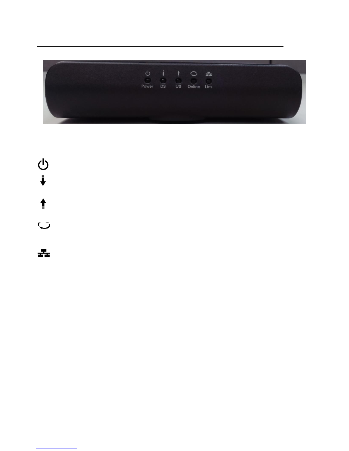
Front Panel
Cable Modem Overview
The following illustration shows the front panel:
Power‐IndicatesthePowerstatus.
DS‐IndicatesthestatusofDatareceptionbythecablemodemfromtheNetwork(Downstream
Traffic).
Fig. 1-1 Front Panel
US‐IndicatesthestatusofDatatransmissionbythecablemodemtotheNetwork(Upstream
Traffic).
Online‐Displaysthestatusofyourcableconnection.Thelightisoffwhennocableconnectionis
detectedandfullylitwhenthemodemhasestablishedaconnectionwiththenetworkand
Link‐IndicatesthestateofEthernetports.
datacanbetransferred.
Page6 / 27
Page 8

TC4310 User’s guide
O
Followingsystemin
itializationcomplet
e t
o (before)DS
X
g
Start-up
DHCP status, LED SHOULD be ON 1
sec, and OFF
1
X
X
The lights on the front panel LEDs are described in the table below (from left to right):
ON = the LED is light, OFF = the LED is gray, FLASH = the LED is blinking.
TC4310 Power DS
US ONLINE LINK
Description
Boot-up
peration
DOCSIS
Operation
Channel
Bonding
Operation
ON
X
ON FLASH OFF OFF
ON
ON
ON
ON FLASH FLASH OFF
FLASH
X
OFF
ON
ON ON ON
FLASH FLASH FLASH X
ON
FLASH OFF
ON
ON FLASH X
ON
ON ON
FLASH FLASH FLASH FLASH
X
X
X
OFF
X
X
X
scanning
During DS scanning and acquiring SYNC
From SYNC completed, receiving UCD to ranging
X
completed
Durin
DHCP, configuration file download,
registration, and Baseline Privacy initialization
sec
Tftp status, LED SHOULD be ON 0.25 sec, and OFF
0.25 sec
Operational (NACO=ON)
Operational (NACO=OFF)
Wait registration with all DS and all US – Lights Flash
sequentially from the right to left
Minimum duration 3 seconds
From 1 to 4 DS, from 1 to 4 LEDs are ON.
From 5 to 8 DS, From 1 to 4 LEDs are flashing
Duration 3 seconds
X
From 1 to 4 US, from 1 to 4 LEDs are ON.
CPE
Operation
SW
Download
Operation
FLASH
FLASH FLASH FLASH FLASH
X
ON FLASH FLASH ON X
X
X
X
FLASH
Table 1-1 LED
Wait registration with all DS and all US – Lights Flash
sequentially from the left to right
OFF
No Ethernet Link
Ethernet Link
ON
TX/RX Ethernet Traffic
A software download and while updating the FLASH
memory
behavior
Page7 / 27
Page 9
TC4310 User’s guide
Rear Panel
Connector Description
Power Jack
Etherent
Reset
Fig. 1-2 Rear Panel
Connector for DC12V.
Ethernet ports, 10/100/1000BaseT RJ-45 connector.
To restart the modem or press over 5 seconds can
default the modem.
Cable
Connector for the cable network.
Table 1- 2 Re ar Pa ne l
description
Page8 / 27
Page 10

TC4310 User’s guide
Wall Mounting
The number of the screw: 2 pcs.
Direction for wall mounting: Tuner downward or leftward or rightward.
Dimension for the screw: diameter: 3.5mm; length: 10mm.
Note: When wall mounting the unit, ensure that it is within reach of the power outlet.
Fig. 1-3 Wall Mounting
To do this:
1. For THE CABLE MODEM, ensure that the wall you use is smooth, flat, dry and sturdy
and use the 2 screw holes.
There are 2 slots on the underside of the CABLE MODEM that can be used for wall mounting.
2. The unit can be to use solid concrete wall and/ or hard wood wall.
Page9 / 27
Page 11

TC4310 User’s guide
Relationship among the Devices
This illustration shows a cable company that offers DOCSIS/Euro-DOCSIS compliant data services.
What the Modem Does
Fig. 1-4 Connection overview
The Cable Modem provides high-speed Internet access as well as cost-effective, commercial, and
education subscribers on public and private networks via an existing CATV infrastructure. The IP traffic
can transfer between the Cable Modem and DOCSIS/Euro-DOCSIS compliant head-end equipment. The
data security secures upstream and downstream communications.
What the Modem Needs to Do Its Job
The Right Cable Company: Make sure your local cable company provides data services that use
cable TV industry-standard DOCSIS/Euro-DOCSIS compliant technology.
Check with your cable company to make sure you have everything you need to begin; they’ll know if you
need to install special software or re-configure your computer to make your cable internet service work
for you.
Contact Your Local Cable Company
You will need to contact your cable company to establish an Internet account before you can use your
cable modem. You should have the following information ready (which you will find on the sticker on the
cable modem):
The serial number
The model number
The Cable Modem (CM) Media Access Control (MAC) address
Page10 / 27
Page 12

TC4310 User’s guide
Please check the following with the cable company
The cable service to your home supports DOCSIS/Euro-DOCSIS compliant two-way modem
access.
Your internet account has been set up.
You have a cable outlet near your PC and it is ready for Cable Modem service.
Note: It is important to supply power to the modem at all times. Keeping your modem plugged in will
keep it connected to the Internet. This means that it will always be ready whenever you need.
Important Information
Your cable company should always be consulted before installing a new cable outlet. Do not attempt any
rewiring without contacting your cable company first.
Please verify the following on the Cable Modem
The Power LED should be lighted when plug-in the power supply.
Connecting the Cable Modem to a Single Computer
This section of the manual explains how to connect your Cable Modem to the Ethernet port on your
computer and install the necessary software. Please refer to Figure 1-5 to help you connect your Cable
Modem for the best possible connection.
Fig. 1-5 Basic Home
Wiring
Page11 / 27
Page 13

TC4310 User’s guide
Attaching the Cable TV Wire to the Cable Modem
a. Connected directly to a TV, a Cable TV converter box, or VCR. The line will be connected to
the jack, which should be labeled either IN, CABLE IN, CATV, CATV IN, etc.
1. Locate the Cable TV wire. You may find it one of three ways:
b. Connected to a wall-mounted cable outlet.
c. Co ming out from under a baseboard heater or other location. See Figure 1-6 for the wiring
example.
Notes:Foroptimumperformance,besuretoconnectyour
CableModemtothefirstpointthecableentersyourhome.
Thesplittermustberatedforatleast1GHz.
Fig. 1-6 Connect to the
Modem
Page12 / 27
Page 14

TC4310 User’s guide
Installation procedure for connecting t o the Ethernet interface
Follow these steps for proper installation.
Plug the coaxial cable to the cable wall outlet and the other end to the modem’s cable connector.
Note: To ensure a fast registration of the modem, the coaxial cable must be connected to
the modem before it is powered on.
Plug the power supply into the socket of the cable modem and two-pin plug in the AC outlet then press
the Power Switch, power on the modem.
Note: Only use the power supply that comes with the modem. Using another power supply
can cause damage to the product, and will void the warr a nt y.
Connect an Ethernet cable (direct connection, see below) to the Ethernet port at the back of the computer,
and the other end to the ETHERNET port on the rear panel of the cable modem. The modem will seek the
appropriate cable signal on the cable television network and go through the initial registration process on
its own. The modem is ready for data transfer after the green LED "ONLINE" is lit continuously.
Note: the button "reset" at the back of the modem is used primarily for maintenance.
Page13 / 27
Page 15

TC4310 User’s guide
Connecting More Than Two Computers to the Cable Modem
If you need to connect two or more computers, you’ll need the following additional equipment (if
supported by your cable operator):
● Crossover-wired, or “null,” category 5 Ethernet cable for the cable modem to be connected to the hub
● 10/100/1000BaseT Hub or Switch.
● Straight through, or standard, category 5 Ethernet cable (one for each computer to be connected)
If you have a hub with an uplink port, a straight through cable can be used in combination with that port
in lieu of the crossover cable.
An uplink port has a small switch on it to change the polarity of the connection. It can accept either a
crossover or a straight cable, depending on the setting.
Note: You may need to check with your service provider in order to connect multiple
Fig. 1-7 Connect multiple PC to Cable Modem.
computers.
Page14 / 27
Page 16

TC4310 User’s guide
CHAPTER 2: WEB CONFIGURATION
To make sure that you can access the Internet successfully, please check the following first.
1. Make sure the connection (through Ethernet) between the Cable Modem and your computer is OK.
2. Make sure the TCP/IP protocol is set properly.
3. Subscribe to a Cable Company.
Accessing the Web Configuration
The Cable Modem offers local management capability through a built-in HTTP server and a number of
diagnostic and configuration web pages. You can configure the settings on the web page and apply them
to the device.
Once your host PC is properly configured; please proceed as follows:
1. Start your web browser and type the private IP address of the Cable Modem on the URL
field: 192.168.100.1
2. After connecting to the device, you will be prompted to enter username and password. By
default, the username is “ ” (empty) and the password is “admin”.
If you login successfully, the main page will app ear.
Fig2-1 Login
dialogue
Page15 / 27
Page 17

TC4310 User’s guide
Outline of Web Manager
The main screen will be shown as below.
Fig. 2-2 Outline of Web
Manager
Menu: For entering each function, e.g., Status
Title: the sidebar on the left side of the page indicates the title of this management interface, e.g.,
Software in this example
Main Window: the current workspace of the web management, containing configuration or status
information
For easy navigation, the pages are organized in groups with group in names main menu. Individual page
names within each group are provided in the sub menu and sidebar. So to navigate to a page, click the
group hyperlink at the top, then the sub menu for the function, finally choose the title on the sidebar.
Your cable company may not support the reporting of some items of information listed on your cable
modem’s internal web pages. In such cases, the information field appears blank. This is normal.
Page16 / 27
Page 18

TC4310 User’s guide
Warning message to change the password
At your first connection or while the password is the default one, a warning message is displayed on the
top banner of each Web configuration page. We want to encourage you to change the password in order
to enforce the security of your modem. Please refer to the chapter Password on page 20 for more
information.
To change the password: type the original password, and re-enter it again.
Fig. 2-3
Status\Password
Note: If forget your username and password, you may Press "Reset" button on the rear
panel more than 5seconds to restore the username and password to default.
Page17 / 27
Page 19

TC4310 User’s guide
Status Web Page Group
Software
The information section shows the hardware and software information about your cable modem.
The status section of this page shows how long your cable modem has operated since last time being
powered up, and some key information the Cable Modem received during the initialization process with
your cable company. If Network Access shows “Allowed,” then your cable company has configured your
cable modem to have Internet connectivity. If not, you may not have Internet access, and should contact
your cable company to resolve this.
Fig.2-4
Status\Software
Page18 / 27
Page 20

-
-
4
4
V
V
4
4
z
V
V
TC4310 User’s guide
Connection
This page reports current connection status containing startup procedures, downstream and upstream
status, CM online information, and so on. The information can be useful to your cable company’s support
QAM256
QAM256
Modulation
QAM6
QAM6
QAM6
QAM6
02 H
D
: D M:
Channel
Channel ID
DD
S:
n on
the
status of the cable modem's
I
stat
I
OK
t
r
ID Symbol Rate Frequency
3
4
5
6952000
6
7
6952000
8
2
1
3
4
DD
Comment
us
~
Locked
Operational
Operational
Disabled
6952000
6952000
6952000
6952000
6952000
6952000
Symbol Rat
5120 Ksym/sec
5120 Ks
5120 Ks
5120
27
ym/sec
ym/sec
Ksym/sec
2015
e
333000000
341
349000000
357000000
365000000
373000000
381 000000
389000000
-
Hz -0.9 dBmV 48.5 dB
000000
Hz -0.7 dBmV 48.6 dB
Hz -0.5 dBmV 49.9
Hz -0.7 dBmV 48.6 dB
Hz -04 dBmV 48.5 dB
Hz -0.5 dBmV 49.8 dB
Hz -0.5 dBmV 49.8 dB
Hz -0.8 dBmV 49.9 dB
F
requency
1600
0000 Hz
9000000
23000000
30000000 H
Power
Hz
Hz
Power
36.0 dB
35.7 dB
35.
7 dBm
36.0 dBm
SNR
m
m
HFC
and JP network
dB
L
ogout
technician if you’re having problems.
techn,color
~
Software
~ Con
Password
Event Log
Initial
nectio
Scan
n
Status
Connection
co
nnectivity.
Startup Procedure
Procedu
Acquire Downstream Channel
Connectivity
Boot State
Configuration
Security Disabled
Downstream Channel
Channel Lock Status Modulation
Upstream Channel
Ch annel
This page displays informatio
re
State
File OK
Locked
Locked
3
Locked
Locked
4
Locked QAM256
5
Locked QAM256
6
7
Locked QAM256
8
Locked QAM256
LockStatus
Locked
Locked
2
3
Locked
4
Locked
10.10.161 37
.
D
:
Status
Current
System Time: Thu May 07 11: 44:
Fig. 2-5
Status\Connection
Page19 / 27
Page 21

TC4310 User’s guide
Password
By default, the username is empty (“”) and the password is “admin”.
This is set by different actions (non exhaustive list):
‐f ollowing a reset to factory default on the modem
‐f ollowing a reset from the Cable Operator
‐following a change by the user who wants to come back to the default setting after using its own
settings
When the current password is the default one, the user is strongly encouraged to change the default web
password.
At your first connection or while the password is the default one, a warning message is displayed on the
top banner of each Web configuration page. We want to encourage you to change the password in order
to enforce the security of your modem.
The password can be a maximum of 8 characters and is case sensitive. In addition, this page can be used
to restore the cable modem to its original factory settings. Use this with caution, as all the settings you
have made will be lost. To perform this reset, set Restore Factory Defau l ts to Yes and click Apply. This
has the same effect as a factory reset using the rear panel reset switch, where you hold on the switch for 5
seconds, then release it.
Note: We are always suggesting you to modify the password. This is a basic protection against wrongful
access to the Cable modem Web pages.
Fig. 2-6
Status\Password
Page20 / 27
Page 22

TC4310 User’s guide
To change the password: type the password, and re-enter it again.
If the password is no accepted, an error message is displayed:
Pleasepress"TRYAGAIN",thentypingthecorrectusernameandpasswordagain.
Page21 / 27
Page 23

TC4310 User’s guide
Event Log
This page displays the contents of the event log. Event log are some important events happened on the
cable modem in the past. Those information are important to your Cable Company if you are having
trouble to get internet access.
Press “Clear Log” button to clear the logs.
Fig. 2-7 Status\Event
Log
Page22 / 27
Page 24

TC4310 User’s guide
Initial Scan
To speed up the modem’s first time connection, enter known downstream frequency and/or upstream
channel ID information here. Then click “Apply and Reboot” button to start scanning the cable network
beginning with the values supplied here. Check your Cable Company for the frequency you need to enter
if you need to set this up by yourself.
The value is provided in Hertz. So, for 333 MHz, you must type: 333000000.
Fig. 2- 8 S ta tus\Initial
Scan
Page23 / 27
Page 25

TC4310 User’s guide
CHAPTER3: ADDITIONAL INFORMATION
Frequently Asked Questions
Q. What if I don’t subscribe to cable TV?
A. If cable TV is available in your area, data service may be made available with or without cable TV
service. Contact your local cable company for complete information on cable services, including highspeed internet access.
Q. How do I get the system installed?
A. Professional installation from your cable provider is strongly recommended. They will ensure proper
cable connection to the modem and your computer. However, your retailer may have offered a self
installation kit, including the necessary software to communicate wi th your cable ISP.
Q. Once my Cable Modem is connected, how do I get access to the Internet?
A. Your local cable company provides your internet service*, offering a wide range of services including
email, chat, and news and information services, and a connection to the World Wide Web.
Q. Can I watch TV, surf the Internet, and talk to my friends through the Cable Modem at the same
time?
A. Absolutely!
Q. Can I run more than one computer on the modem?
A. Yes – a single cable modem can support up to 32 computers using Ethernet connectivity.
Q. What do you mean by “Broadband?”
A. Simply put, it means you’ll be getting information through a “bigger pipe,” with more bandwidth, than
a standard phone line c an offer. A wider, “broader” band means more informati on, more quickly.
Q. What is Euro-DOCSIS and what does it mean?
A. “Data over Cable Service Interface Specifications” is the industry standard that most cable companies
are adopting as they upgrade their systems. Should you ever decide to move, the Cable Modem will
work with all upgraded cable systems that is DOCSIS-compliant.
* Monthly subscription fee applies.
** Additional equipment required. Contact your Cable Company and ISP for any restrictions or additional
fees.
Page24 / 27
Page 26

TC4310 User’s guide
General Troubleshooting
You can correct most problems you have with your product by consulting the troubleshooting list that
follows.
I can’t access the internet.
Check all of the connections to your Cable Modem.
Your Ethernet card may not be working. Check each product’s documentation for more information.
The Network Properties of your operating system may not be installed correctly or the settings may
be incorrect. Check with your ISP or cable company.
I can’t get the modem to establish an Ethernet connec tion.
Even new computers don’t always have Ethernet capabilities – be sure to verify that your computer
has a properly installed Ethernet card and the driver software to support it.
Check to see that you are using the right type of Ethernet cable.
The modem won’t register a cable connection.
If the modem is in Initialization Mode, the INTERNET light will be flashing. Call your Cable
Company if it has not completed this 5-step process within 30 minutes, and note which step it is
getting stuck on.
The modem should work with a standard RG-6 coaxial cable, but if you’re using a cable other than
the one your Cable Company recommends, or if the terminal connections are loose, it may not work.
Check with your Cable Company to determine whether you’re using the correct cable.
If you subscribe to video service over cable, the cable signal may not be reaching the modem.
Confirm that good quality cable television pictures are available to the coaxial connector you are
using by connecting a television to it. If your cable outlet is “dead”, call your Cable Company.
Verify that the Cable Modem service is Euro-DOCSIS compliant by calling your cable provider.
Page25 / 27
Page 27

TC4310 User’s guide
Service Information
If you purchased or leased your Cable Modem directly from your cable company, then warranty service
for the Digital Cable Modem may be provided through your cable provider or its authorized
representative. For information on 1) Ordering Service, 2) Obtaining Customer Support, or 3) Additional
Service Information, please contact your cable company. If you purchased your Cable Modem from a
retailer, see the enclosed warranty card.
Page26 / 27
Page 28

TC4310 User’s guide
Glossary
10/100/1000 BaseT – Unshielded, twisted pair cable with an RJ-45 connector, used with Ethernet LAN
(Local Area Network). “10/100/1000” indicates speed (10/100/1000 BaseT), “Base” refers to baseband
technology, and “T” means twisted pair cable.
Authenticatio n - The process of verifying the identity of an entity on a network.
DHCP (Dynamic Host Control Protocol) – A protocol which allows a server to dynamically assign IP
addresses to workstations on the fly.
Ethern et a d ap t ers – A p lug-in circuit board installed in an exp ansion slot of a personal computer. The
Ethernet card (sometimes called a Network Interface Card , network adapter or NIC) takes parallel data
from the computer, converts it to serial data, puts it into a packet format, and sends it over the
10/100/1000 BaseT LAN cable.
DOCSIS (Data Over Cable Service Interface Specifications) – A project with the objective of
developing a set of necessary specifications and operations support interface specifications for Cable
Modems and associated equipment.
F Connector – A type of coaxial connector, labeled CABLE IN on the rear of the Cable Modem that
connects the modem to the cable system.
HTTP (HyperText Transfer Protocol) – Invisible to the user, HTTP is used by servers and clients to
communicate and display information on a client browser.
IP Address – A unique, 32-bit address assigned to every device in a network. An IP (Internet Protocol)
address has two parts: a network address and a host address. This modem receives a new IP address from
your cable operator via DHCP each time it goes through Initialization Mode.
MAC Address – The permanent “identity” for a device programmed into the Media Access Control layer
in the network architecture during the modem’s manufacture.
TCP/IP (Transmission Control Protocol/Internet Protocol) – A networking protocol that provides
communication across interconnected networks, between computers with diverse hardware architectures
and various operating systems.
TECHNICOLOR Inc.
101 W. 103rd St., INH700 Indianapolis, IN. 46290 USA
Tel: +1 (317) 587-3000 - Fax: +1 (317) 587-6763
www.technicolor.com
Page27 / 27
 Loading...