


DIRECTV COM1000
Integrator's Manual
Software Version
ST02.08.07
REV. 2.72

Contents
1 |
INTRODUCTION............................................................................... |
10 |
|
2 COM1000 PRODUCT DESCRIPTION .................................................... |
13 |
||
3 |
MECHANICAL OVERVIEW .................................................................. |
17 |
|
|
3.1 |
COM200 Front View ................................................................................................ |
17 |
|
3.2 |
COM200 Rear View ................................................................................................. |
18 |
|
3.3 |
COM24 Card............................................................................................................ |
19 |
|
3.4 |
COM24FLX Card ...................................................................................................... |
20 |
|
3.5 |
GbE Card ................................................................................................................. |
21 |
|
3.6 |
XDR24 Card............................................................................................................. |
21 |
|
3.7 |
QAM24 Board ......................................................................................................... |
21 |
4 |
GETTING STARTED........................................................................... |
24 |
|
|
4.1 |
Setting up Multiple Chassis...................................................................................... |
24 |
|
4.2 |
Installation Requirement Guidelines........................................................................ |
27 |
|
4.2.1 General System Guidelines ......................................................................................... |
27 |
|
|
4.2.2 System Integrator Guidelines ..................................................................................... |
28 |
|
|
4.2.3 System Operator Guidelines ....................................................................................... |
28 |
|
5 |
CONFIGURING THE SYSTEM................................................................ |
30 |
|
|
5.1 |
Useful tools............................................................................................................. |
30 |
|
5.1.1 Configuration tool ...................................................................................................... |
30 |
|
|
5.1.2 DHCP Server................................................................................................................ |
30 |
|
|
5.1.3 Video Playback ........................................................................................................... |
31 |
|
|
5.1.4 System Logging........................................................................................................... |
31 |
|
|
5.1.5 TFTP/FTP Server.......................................................................................................... |
31 |
|
|
5.1.6 IP Address Discovery................................................................................................... |
32 |
|
|
5.2 |
Connecting to the COM1000.................................................................................... |
33 |
©2011, 2012 Technicolor. All rights reserved.

5.2.1 Preparing Your Computer’s Network Connections |
..................................................... 33 |
|
5.2.2 Avoiding IP Address conflicts...................................................................................... |
35 |
|
5.3 |
Using a TFTP Server ................................................................................................. |
35 |
5.3.1 Determining Your IP Address...................................................................................... |
35 |
|
5.3.2 Configuring Your TFTP Server..................................................................................... |
37 |
|
6 USING THE COM1000 WEB INTERFACE ............................................... |
43 |
|
6.1 |
Discovery of COM24 and COM24FLX Cards ............................................................. |
43 |
6.1.1 Fields prior to ST02.05.05 no longer present ............................................................. |
47 |
|
6.1.2 Fields present after ST02.05.05 .................................................................................. |
47 |
|
6.2 |
Scanning for COM24 Cards ...................................................................................... |
49 |
6.3 |
Refreshing the COM1000 Display............................................................................. |
51 |
6.4 |
Displaying COM1000 Status..................................................................................... |
52 |
6.5 |
Evaluating COM24 Authorization Status .................................................................. |
54 |
6.6 |
Evaluating COM1000 System Status......................................................................... |
58 |
6.7 |
Evaluating COM1000 Health Status ......................................................................... |
60 |
6.8 |
The Tune Command ................................................................................................ |
63 |
6.8.1 Tuning the COM24 Cards ........................................................................................... |
64 |
|
6.8.2 Evaluating COM24 Informational Status ................................................................... |
68 |
|
6.8.3 Using the COM24 “Direct Tune” Feature ................................................................... |
70 |
|
6.8.4 Using the COM24 LED Control Feature ...................................................................... |
71 |
|
6.8.5 Using the COM24 File Transfer Utility........................................................................ |
72 |
|
6.8.6 Setting the COM24 User Configuration Options ........................................................ |
74 |
|
6.8.7 Reading the COM24 CAM Log Data ........................................................................... |
75 |
|
6.8.8 Using the COM24 Software Reset Feature................................................................. |
79 |
|
6.9 |
Using the COM1000 TuneAll Command ................................................................... |
80 |
6.10 |
Using the DIRECTV Electronic Program Guide (EPG) ................................................. |
83 |
6.10.1 Starting Out .............................................................................................................. |
85 |
|
6.10.2 Configuring the EPG ................................................................................................. |
89 |
|
6.10.3 Adding a Logo to the EPG......................................................................................... |
92 |
|
3

|
6.11 |
Using the COM24 Syslog Command ......................................................................... |
93 |
|
|
6.12 |
Using the COM24 ATSC Command ........................................................................... |
94 |
|
|
6.13 |
Using the COM24 401 Command ............................................................................. |
95 |
|
|
6.14 |
Using the COM24 QAM Command........................................................................... |
96 |
|
|
6.15 |
Using the COM24 Help Command............................................................................ |
99 |
|
7 COM1000 FIRMWARE UPGRADE PROCEDURES................................... |
100 |
|||
|
7.1 |
Preparing for a Firmware Upgrade......................................................................... |
100 |
|
|
7.2 |
Upgrading COM24 Firmware ................................................................................. |
100 |
|
|
7.3 |
Upgrading a FLX24 from SD to HD.......................................................................... |
103 |
|
|
7.4 |
Upgrading QAM24 Firmware ................................................................................. |
104 |
|
8 |
COM1000 DIAGNOSTIC CAPABILITIES ............................................... |
107 |
||
|
8.1 |
Indicator lights ...................................................................................................... |
107 |
|
|
8.1.1 Power Supply Issues.................................................................................................. |
107 |
||
|
8.1.2 System Startup ......................................................................................................... |
108 |
||
|
8.1.3 Normal Operation .................................................................................................... |
109 |
||
|
8.1.4 Software Upgrade .................................................................................................... |
110 |
||
|
8.2 |
Network Connectivity Indicators ........................................................................... |
112 |
|
9 |
DIRECTV AUTHORIZATION ............................................................. |
113 |
||
10 GENERAL TROUBLESHOOTING TIPS .................................................... |
114 |
|||
|
10.1 |
Testing Video without Pro:Idiom Encryption.......................................................... |
114 |
|
|
10.1.1 Streaming Video to a Standard Television ............................................................. |
114 |
||
|
10.1.2 Streaming Video to your PC.................................................................................... |
115 |
||
|
10.2 |
Preventing Pro:Idiom key loss ............................................................................... |
117 |
|
|
10.3 |
Changing the Input................................................................................................ |
118 |
|
|
10.4 |
Verifying Card Authorization ................................................................................. |
118 |
|
Appendix A |
COM24 IP CONFIGURATION CONSIDERATIONS .................... |
119 |
||
Appendix B |
RF SANITY CHECK .......................................................... |
124 |
||
4

Appendix C TROUBLESHOOTING THE COM1000 .................................. |
125 |
List of Figures |
|
Figure 1 – COM1000 System Overview ...................................................................................... |
14 |
Figure 2 – COM200 Front View................................................................................................... |
17 |
Figure 3 – COM200 Rear View.................................................................................................... |
18 |
Figure 4 - COM24 Card................................................................................................................ |
19 |
Figure 5 - COM24FLX Card ........................................................................................................ |
21 |
Figure 6 – QAM24 Board installed in Chassis ............................................................................. |
22 |
Figure 7 – QAM24 Front View .................................................................................................... |
23 |
Figure 8 – COM200 Chassis ID Configuration Switch Location................................................. |
25 |
Figure 9 – COM200 Chassis ID Configuration Switch Closeup .................................................. |
25 |
Figure 10 - COM24FLX to SWM Module connections............................................................... |
29 |
Figure 10 – Results from the COM24 Discovery Tool................................................................. |
32 |
Figure 11 – Network Connections Window ................................................................................. |
33 |
Figure 12 – Internet Protocol Configuration................................................................................. |
34 |
Figure 14 – Accessing the Command Prompt window ................................................................ |
36 |
Figure 15 – Running ipconfig ....................................................................................................... |
36 |
Figure 16 – Tftpd32 Startup Screen .............................................................................................. |
38 |
Figure 17 – Tftpd32 Settings Window (Global Settings).............................................................. |
39 |
Figure 18 – Tftpd32 Settings Window (TFTP Settings) ............................................................... |
40 |
Figure 19– Tftpd32 Settings Window (Syslog Settings) .............................................................. |
41 |
Figure 20 – Tftpd32 File Transfer Progress Screen ...................................................................... |
42 |
Figure 21 – Tftpd32 Completed Transfer Screen.......................................................................... |
42 |
Figure 22 - COM1000 Web Based User Interface Introduction Page .......................................... |
43 |
Figure 23 - COM24 Discover Page .............................................................................................. |
44 |
Figure 24 - Discover Page w. COM24FLX .................................................................................. |
45 |
Figure 25 – COM1000 Discover Page (showing colors).............................................................. |
46 |
5

Figure 26 – COM1000 Scan Page ................................................................................................ |
50 |
Figure 27 – COM1000 Refresh Page............................................................................................ |
52 |
Figure 28 – COM1000 Display Page............................................................................................ |
53 |
Figure 29 – COM1000 Pairing Info Page ..................................................................................... |
54 |
Figure 30 – COM24 Multi-card Upgrade Feature ........................................................................ |
56 |
Figure 31 – COM24 Multi-card Upgrade Results Page................................................................ |
57 |
Figure 32 – COM1000 SysInfo Page ............................................................................................ |
58 |
Figure 33 – COM1000 HealthInfo Page ....................................................................................... |
60 |
Figure 34 – COM24 Basic Tune Screen ....................................................................................... |
63 |
Figure 35 – Advanced Tune screen portion of Advanced Edit page ............................................ |
65 |
Figure 36 – “Info” Section on Advanced Edit Page. .................................................................... |
68 |
Figure 37 – “Direct Tune” Interface on Advanced Edit page....................................................... |
70 |
Figure 38 – “LED Control” Interface on Advanced Edit page ..................................................... |
71 |
Figure 39 – “File Transfer” Interface on Advanced Edit page ..................................................... |
72 |
Figure 40 – “User Config” Interface on Advanced Edit page ...................................................... |
74 |
Figure 41 – “CAM Log” Interface on Advanced Edit page ......................................................... |
76 |
Figure 42 – CAM Log Report....................................................................................................... |
77 |
Figure 43 – “Reset” Interface on Advanced Edit page ................................................................. |
79 |
Figure 44 – COM1000 TuneAll Page............................................................................................ |
80 |
Figure 45 – COM1000 EPG Page ................................................................................................ |
85 |
Figure 46 – COM1000 EPG Page (Configured)........................................................................... |
88 |
Figure 47 – COM24 EPGLoad Result .......................................................................................... |
89 |
Figure 48 – Guide Channel (EPG)................................................................................................ |
91 |
Figure 49 – EPG Logo Adjustments............................................................................................. |
92 |
Figure 50 – Guide Channel (EPG) with Custom Logo................................................................. |
92 |
Figure 51 – COM24 Syslog Report .............................................................................................. |
93 |
Figure 53 – QAM24 Command Screen (bottom portion)............................................................. |
97 |
Figure 54 – COM24 Help Command............................................................................................ |
99 |
Figure 55 – Multi-card COM24 SW Upgrade ............................................................................ |
101 |
Figure 56 – Multi-card COM24 SW Upgrade Results ............................................................... |
102 |
6

Figure 58 – QAM24 SW Upgrade .............................................................................................. |
105 |
|
Figure 59 – QAM24 SW Upgrade Results ................................................................................. |
106 |
|
Figure 60 |
– Network Connectivity Indicator LEDs.................................................................... |
112 |
Figure 61 |
– Configuring VLC Media Player .............................................................................. |
115 |
Figure 62 |
– Opening a Network Stream ..................................................................................... |
116 |
Figure 63 |
– Streaming Video from a COM24 Card ................................................................... |
117 |
|
List of Tables |
|
Table 1 – Definition of Terms ...................................................................................................... |
10 |
|
Table 2 – COM200 Chassis ID Configuration ............................................................................. |
27 |
|
Table 3 |
– LED States .................................................................................................................. |
107 |
Table 4 |
– LED Startup Behavior ................................................................................................ |
108 |
Table 5 |
– LED Behavior during Normal Upgrade...................................................................... |
110 |
Table 6 |
– RF Spot Check Values ................................................................................................ |
124 |
7

THIS PAGE IS INTENTIONALLY
BLANK
8

THIS PAGE IS INTENTIONALLY
BLANK
9

1 INTRODUCTION
This document describes the processes and procedures for configuring a COM1000 system. The following sections will provide a brief overview of the system hardware, an in-depth guide to the COM24 user interface, and descriptions of certain system processes. Also included are several indices that cover common troubleshooting problems.
It is recommended that you read through the entirety of the manual, or at least review the main sections before working with the system, as it contains some important pointers that may come in handy during setup and maintenance.
The table below provides an explanation of some useful terms and device names that will be referred to throughout the manual. You should use these terms to familiarize yourself with the different aspects of the system before proceeding any further.
|
|
|
Table 1 – Definition of Terms |
|
|
|
|
|
|
|
Term |
|
Definition |
|
|
|
|
|
|
|
|
|
This is the complete system, consisting of the following: one or more COM100 |
|
|
COM1000 |
|
(now discontinued) or COM200 chassis, COM120 or SWM units, an optional |
|
|
|
gigabit Ethernet switch, and QAM24 cards or alternatively comercial edge |
|
|
|
|
|
QAMs. |
|
|
|
|
|
|
|
|
|
A RF (radio frequency) distribution panel, which is necessary to enable Ka B |
|
|
|
|
|
|
|
COM120 |
|
band signal delivery. The manual will use this device as a reference, but it may |
|
|
|
|
be replaced with a similar device of your choosing. |
|
|
|
|
|
|
|
|
|
|
|
|
|
|
A chassis that can support up to 12 receiver cards. This chassis contains an |
|
|
COM200 |
|
integrated gigabit Ethernet switch and Ethernet Card, but does not include |
|
|
|
other necessary equipment such as an edge QAM device, Ethernet switches, or |
|
|
|
|
|
RF distribution and signaling electronics. |
|
|
|
|
|
|
|
|
|
The first-generation chassis of the COM1000 series chassis, similar in structure |
|
|
|
|
|
|
|
COM100 |
|
to the COM200 but lacking backplane Ethernet connections. This product was |
|
|
|
|
discontinued in 2010. |
|
|
|
|
|
|
|
|
|
|
|
10
|
Term |
|
|
Definition |
|
|
|
|
|
|
|
|
COM24 |
|
Individual DIRECTV receiver card that fits within a COM200 chassis and is |
|
|
|
|
|
|
capable of sourcing 2 DIRECTV HD or SD channels. |
|
|
|
|
|
|
|
|
|
|
|
Individual DIRECTV receiver card that fits within a COM200 chassis and is |
|
|
|
|
|
|
|
|
COM24FLX |
|
|
capable of sourcing 3 DIRECTV SD channels. Software upgradeable to 2 HD |
|
|
|
|
|
channels with a software upgrade license purchase. |
|
|
|
|
|
|
|
|
|
|
|
|
|
|
|
|
|
The QAM6 is an optional circuit board (i.e., internal Edge QAM) that replaces |
|
|
|
|
|
the Ethernet Card in the upper left side of a COM200 Chassis. The board |
|
|
QAM6 |
|
provides 6 QAM channels in addition to a system management Ethernet port. |
|
|
|
|
|
|
Each QAM channel can carry 2 HD or 8 SD video channels. The QAM6 can be |
|
|
|
|
|
expanded up to 12 QAM channels, 2 at a time, by purchasing a SWQAM2. |
|
|
|
|
|
|
|
|
|
|
|
The SWQAM2 is a software key that will enable 2 QAM channels per key on a |
|
|
|
|
|
|
|
|
SWQAM2 |
|
|
QAM6 card. By pruchasing 3 SWQAM2 keys a QAM6 can be expanded to 12 |
|
|
|
|
|
QAM channels. |
|
|
|
|
|
|
|
|
|
|
|
|
|
|
|
|
|
An optional circuit board (i.e., internal Edge QAM) that replaces the Ethernet |
|
|
|
|
|
Card in the upper left side of a COM200 Chassis. The board provides 12 QAM |
|
|
QAM24 |
|
channels in addition to a system management Ethernet port. Each QAM |
|
|
|
|
|
|
channel can carry 2 HD or 8 SD video channels. This product has been replaced |
|
|
|
|
|
by the QAM6 and the SWQAM2. |
|
|
|
|
|
|
|
|
ATSC8 |
|
|
An optional eight channel off-air ATSC receiver that may be connected to and |
|
|
|
|
|
||
|
|
|
configured from a COM1000 system. |
|
|
|
|
|
|
|
|
|
|
|
|
QAM (Quadrature Amplitude Modulation) is the format by which digital cable |
|
|
Edge QAM |
|
channels are encoded and transmitted. An edge QAM is a device built to carry |
|
|
|
|
|
|
both video-on-demand and switched digital video streams. Makers include |
|
|
|
|
|
Technicolor, Arris, Harmonic Inc., Motorola, and Scientific-Atlanta/Cisco. |
|
|
|
|
|
|
|
|
|
|
|
An encryption technology used in the hospitality industry for the delivery of |
|
|
Pro:Idiom |
|
|
digital television signals of which Zenith Electronics LLC is the license holder. |
|
|
|
|
|
||
|
|
|
This is the encryption standard around which the COM1000 system is |
|
|
|
|
|
|
designed. |
|
|
|
|
|
|
|
11

Term |
|
Definition |
|
|
|
|
|
Transcryption |
|
The process by which the COM 1000 system converts content streaming from |
|
|
|
DIRECTV’s conditional access system to Pro:Idiom encrypted video. |
|
|
|
|
|
“Hot- |
|
The unit or device this term describes may be added to, removed from, or |
|
swappable” |
|
replaced within the system it is a part of without powering anything down. |
|
|
|
|
|
SD |
|
Standard Definition |
|
|
|
|
|
HD |
|
High Definition |
|
|
|
|
|
System |
|
The person or company that performs the onsite installation. |
|
Integrator |
|
|
|
|
|
|
|
System |
|
The company or organization that typically holds the “right of entry” and is |
|
Operator |
|
responsible for installation and all onsite support on a daily basis. |
|
|
|
|
|
SWM |
|
“Single Wire Multiswitch” - DirecTV Module used for selecting up to 8 satellite |
|
a.k.a. SWiM |
|
transponders for TV programs and 1 network transponder. |
|
|
|
|
|
|
|
The first five characters of the COM200 Chassis serial number (e.g., BC009). |
|
Pseudo code |
|
Identifies the version of the chassis. The serial number is found on the label |
|
|
|
on the rear of the COM200 chassis (see Figure 3). |
|
|
|
|
|
|
|
|
|
|
|
The Gigabit Ethernet card (GbE) is a card that when installed in slot 1 of a |
|
GbE |
|
COM200 chassis provides a gigabit speed Ethernet port for use in stacking |
|
|
|
multiple chassis or for injecting ATSC signals into a QAM24 or QAM6. |
|
|
|
|
|
|
|
|
|
12

2 COM1000 PRODUCT DESCRIPTION
A fully populated COM200 chassis is capable of tuning and transcrypting up to 24 DIRECTV HD channels or 36 SD channels. The satellite signal is tuned and demodulated resulting in a DIRECTV Legacy or MPEG-2 transport stream. This transport stream is then IP-encapsulated using standard Internet protocols and RFCs and is sent out via the Ethernet interface. The data leaving the system is in a format suitable for input to an edge QAM device or for distribution on an IPTV network. The original DIRECTV broadcast video encoding format (MPEG-2 or MPEG- 4 compression) is preserved and the output transport stream is encrypted with the Pro:Idiom encryption standard.
Multiple COM200 chassis can be “stacked” in order to provide more than 24 HD or 36 SD output channels. While there is no technical limit to the number of COM200 chassis than can be configured in this manner, the DIP switches used for setting individual chassis IDs are only capable of providing 12 unique identifiers. Refer to Section 4.1 for more information on this topic.
The COM24 receiver cards are controlled and managed via an Ethernet connection and do not contain an internal video decoder for viewing the currently tuned channels. The COM24 card does not operate like a traditional DIRECTV receiver. Specifically, COM24 cards do not perform any MPEG video or audio decoding. They do not provide a traditional Middleware based User Interface, and do not require a remote control device. The COM24 card includes a built-in web interface and must be configured using a web browser. The video output of a COM24 receiver can be viewed on a properly equipped commercial Pro:Idiom television or Pro:Idiom capable set-top box. Manufacturers of this equipment include but are not limited to LG, Phillips, Samsung, Sony, Enseo, and Technicolor.
13
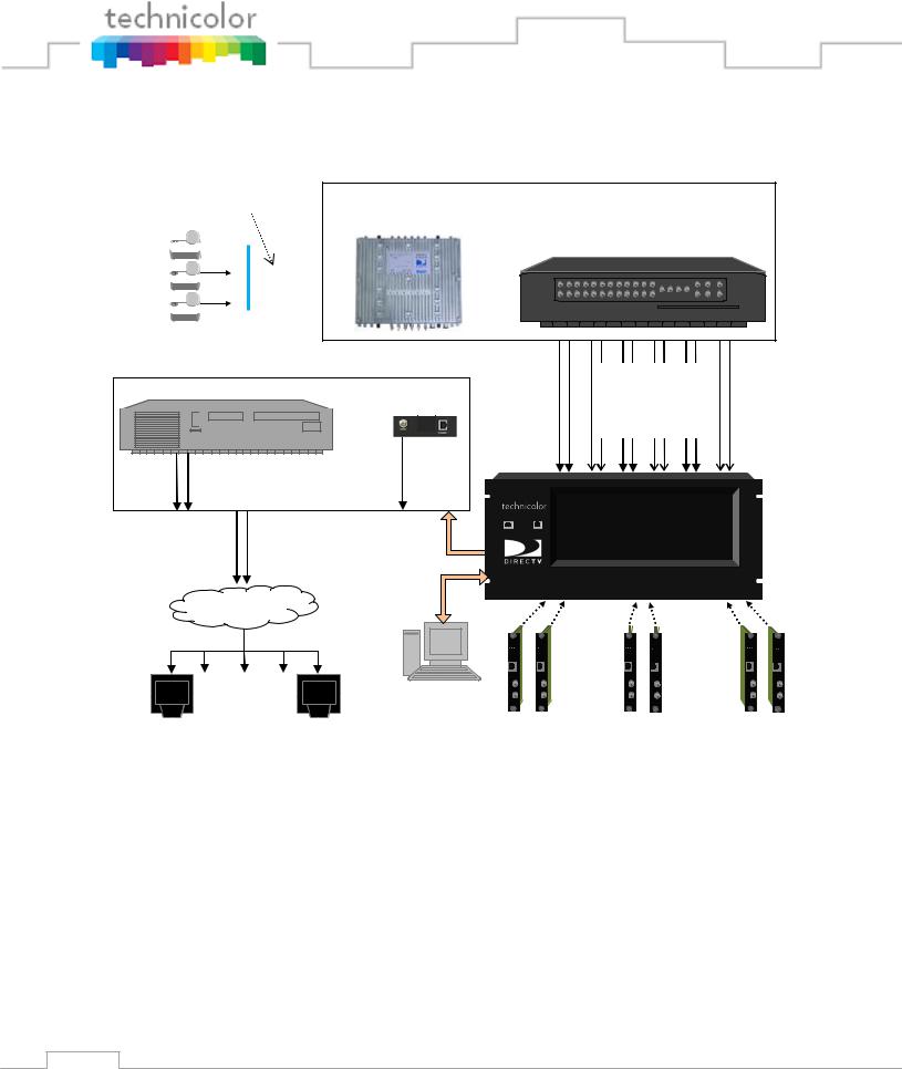
Refer to Figure 1 below for a diagram illustrating a complete COM1000 system.
RF Signal Level: -50dBm to -30dBm per Transponder
LNB 1 


LNB 2 


 LNB 3
LNB 3


SWM32
(Single Wire Multi-switch) |
COM120 |
|
(RF Distribution Panel) |
OR
External Edge QAM
QAM24
OR
COM200
Chassis
RF Signal Level: -55dBm to
-25dBm per Transponder
RF Distribution
TV |
. . . |
TV |
Series of any number of Pro:Idiom enabled Digital TVs with tuners
Admin PC |
. . . |
. . . |
(Optional) |
|
|
Up to… 12 COM24 cards
Figure 1 – COM1000 System Overview
COM1000 System – This describes the entire video distribution system setup as seen above, including all devices and connections that work together to stream DIRECTV HD video programming.
LNB (Low-Noise Block) – This is a device that acts as the antenna of your satellite dish. It receives incoming signals and sends them to the RF distribution panel. Each one is capable of providing two outputs.
14

COM120 (RF Distribution Panel) – This device receives the incoming satellite feed via your dish receiver and distributes the signals using a series of multiswitches. It then sends these signals into the COM24 cards via the RF Inputs (labeled “Tuner 1” and “Tuner 2”).
COM200 Chassis – This device houses the COM24 and COM24FLX cards. All video traffic is routed through the Gigabit Ethernet (GbE) port on the rear of the chassis or to the QAM24. System management and control can be done by connecting a computer to one of the management ports on the Ethernet Card or QAM24 card (i.e., front of the chassis).
Admin PC – This is an optional device and is nonessential to normal system operation. It is recommended, however, as it can be useful in maintaining desired programming and monitoring system function. This can be a desktop or laptop computer equipped with an Ethernet port (or a USB port with Ethernet adapter), any of the recommended applications listed in Section 5.1, and a web browser of your choice.
COM24 and COM24FLX Cards – The bulk of this manual is dedicated to these cards. They are the means by which the property will be able to receive the desired television programming for their network and control the entire COM1000 system.
QAM24 or QAM6 Cards – An optional board that replaces the Ethernet Card in the upper left side of a COM200 Chassis. The board provides up to 12 QAM modulator channels in addition to a 10/100 Ethernet port to an Edge QAM. Each QAM modulator can carry two HD or eight SD video channels.
Edge QAM – In a typical installation, the COM24 cards will be configured to stream to this device. It converts the COM24‟s IP-packetized streams to QAM-modulated RF for distribution throughout a property.
Property Distribution Network – This network, set up and maintained by the System Operator, will distribute any channels provided by the property. It may consist of any configuration of devices as defined by the System Operator.
Pro:Idiom Enabled Televisions – It is important to note that some Pro:Idiom compliant televisions only support MPEG-2 video compression. The COM24 card is agnostic to the
15

content compression type and it will stream either MPEG-2 or MPEG-4 encoded transport streams.
16
3 MECHANICAL OVERVIEW
The following sections contain a brief overview of the devices that you will be interacting with along with the associated hardware. The intent is to give you a working knowledge of how the system operates under normal circumstances so that you will be able to recognize it when something goes wrong.
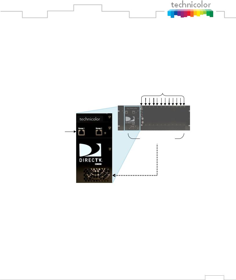
3.1 COM200 Front View
Card Slots #1 – 12
Ethernet Ports
(Management)
Ventilation Grate
Figure 2 – COM200 Front View
Figure 2 above shows the faceplate of the COM200 chassis.
The two Ethernet ports on the far left, combined with the Gigabit Ethernet port in the rear (see Figure 3) allow for direct connections to other devices such as an edge QAM, Ethernet switch, and/or a management PC (optional) and allows any additional chassis in the system to be interconnected. If the chassis is using the QAM24 modulator, it replaces the Ethernet Card (See
Section 3.7).
Along the bottom edge is the ventilation grate, which, combined with the exhaust fans in the back, allow air to flow over the internal system, cooling it.
The majority of the face shows the 12 available card slots, each corresponding to a unique Slot ID, capable of supporting 12 individual cards.
17
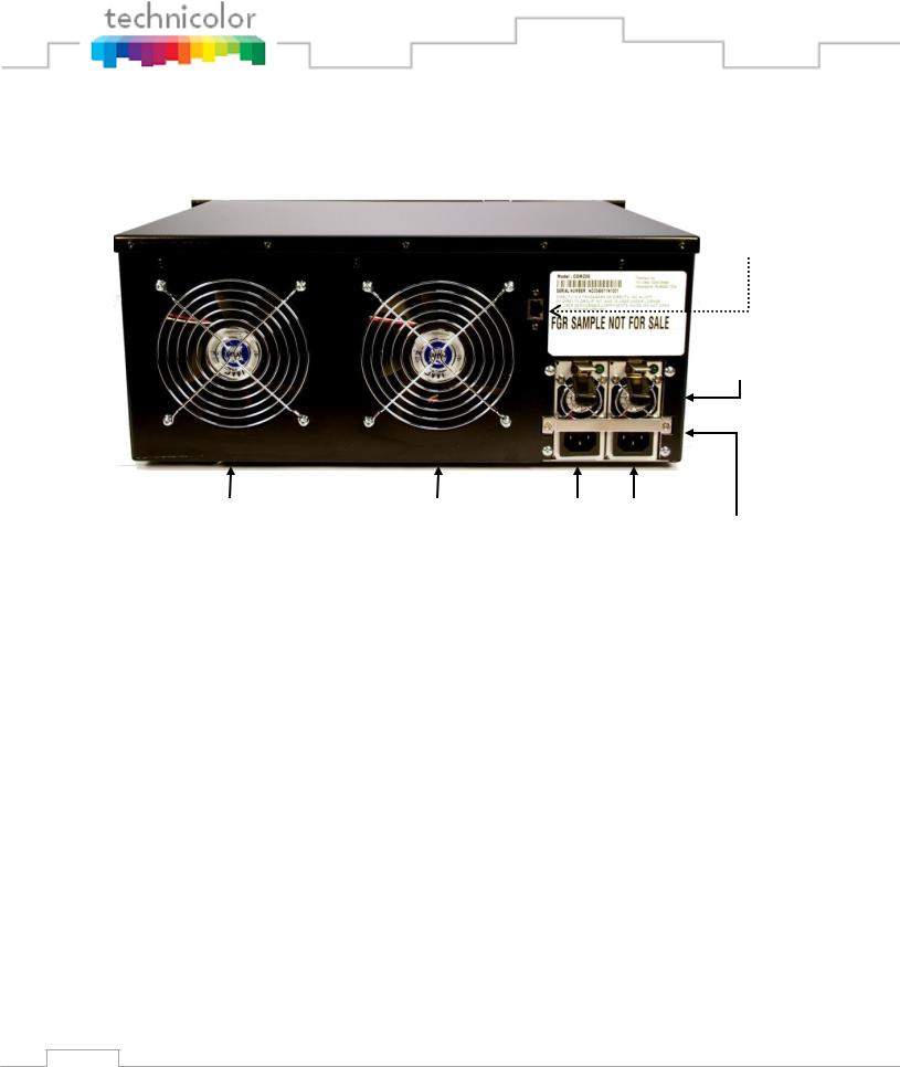
3.2 COM200 Rear View
Gigabit
Ethernet
Port
Power
Supply Fans
Exhaust Fan 1 |
Exhaust Fan 2 |
AC Input 1 AC Input 2 |
|
Rear Mounting
Bracket
Figure 3 – COM200 Rear View
Figure 3 above shows the rear of the COM200 chassis.
The two AC input connections shown at the bottom right provide power to the COM200 chassis. Only a single AC input connection is required in order for the system to operate. However, utilizing both AC input connections creates a DMR (Dual Modular Redundant) system. In other words, the second power unit acts as a backup in case the first power module fails, providing a seamless transition to a functioning power supply. In the case of such an event, the rear mounting bracket just below the power supply fans must be removed in order to replace the failed module. It should be noted that the power supplies are hot-swappable.
The COM200 chassis also contains two 5-inch exhaust fans to provide cooling to the system. Airflow is pulled through the ventilation grate on the front of the COM200 chassis across the COM24 cards and out the back. In the case of an equipment failure, the COM200 chassis can run with just one fan without overheating, but it is recommended that the broken fan is serviced and/or replaced as soon as possible.
The COM200 chassis also contains an integrated Gigabit Ethernet (GbE) port. This port provides the means of routing all COM200 traffic an external edge QAM. If a QAM24 card is installed the external GbE port will NOT available for use as that port will be used to route traffic to the QAM24 card.
18
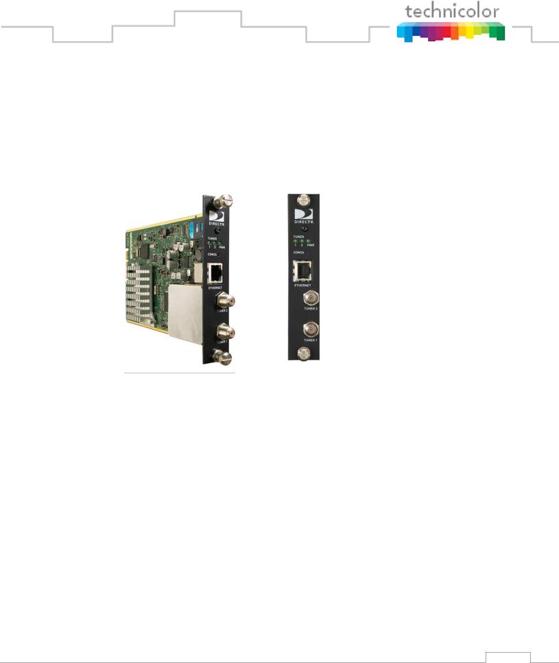
3.3 COM24 Card
The COM24 card is a customized DIRECTV receiver with a built-in smart card and has been specifically designed to meet the unique requirements of the Lodging and Hospitality market.
below shows a detailed picture of the COM24 card.
 Upper Thumbscrew
 Indicator Lights
 Reset Button
 Ethernet Port
 RF Inputs
 Lower Thumbscrew
Figure 4 - COM24 Card
Each COM24 card contains two RF inputs, a 10/100Mbps Ethernet port, three indicator lights, a recessed reset button, and thumbscrews on either end. The cards are hot-swappable, allowing one card to be serviced independently of the other cards. In order to remove a card, simply loosen the thumbscrews that secure the card in place and pull it straight out of its slot.
Each RF input on a COM24 card feeds a dedicated DIRECTV tuner capable of supporting one channel of transcryption. When both RF inputs are connected, the card is capable of streaming two Pro:Idiom encrypted HD channels simultaneously via the Ethernet port. The COM24 is designed such that each tuner on a card only needs to be set once. Once configured, the cards should remain locked unless there is a disruption in the signal due to weather, dish misalignment, or other RF distribution issues. However, the cards will automatically recover when the disruption to the RF is removed.
The COM24 card only works with DIRECTV input signals in the range of 950 - 2150 MHz (when used in conjunction with the required B band converters). Software version ST02.05.11
19

or newer supports SWM (Single-Wire Multiswitch) inputs. A RF distribution panel is required to support the COM200 to enable delivery of Ka B band signals.
If using a SWM, the SWM must be connected to the Tuner1 F connector (lower) and must be powered up at the time that the COM24 is booted since the COM24 only detects a SWM at power on. If the first tuner is receiving HD channels from satellite 103 and a multi-switch is being used, then satellite 119 must also be received for background guide monitoring. However, if using a SWM and receiving HD channels from satellite 103, then satellite 119 reception is not required since satellite 101 will be used for background guide monitoring instead whenever in SWM mode.
See Section 8.1 for an explanation of indicator light diagnostic capabilities.
3.4 COM24FLX Card
The COM24FLX card is a variant of the standard COM24 card that only supports SWM connections. It is configurable as a three channel standard definition or two channel high definition satellite receiver. The COM24FLX as purchased is only capable of receiving SD programming. To upgrade a FLX card to receive two HD channels, a license key must be purchased from Technicolor.
Almost all of the information regarding identification and configuration of the COM24 cards applies to the COM24FLX. The two exceptions are the number of configurable tuners and the upgrade of a COM24FLX from SD to HD. The COM24FLX tuners are configured exactly the same way as the COM24 tuners although if an HD channel is selected the card will return a channel number of 0 in the Discovery page. See Section 6.8 for tuning instructions. See Section7.3 for upgrade instructions.
20
SWM Input
Figure 5 - COM24FLX Card
3.5 GbE Card
The COM200 chassis has an integrated Ethernet switch on the backplane. This switch provides gigabit speed on two ports. One of those is the port on the back of the chassis the other is card slot number one. The gigabit port that is available on the back of the chassis is the port that the QAM24 card uses when it is installed. In order to daisy chain chassis or to inject large amounts of data to the QAM24 in a Colony system you would need another gigabit port and that is where the GbE card comes in. By replacing the card in slot one with the GbE card you now have another gigabit speed Ethernet port that can be used to route data to the QAM24 card in that chassis. This card is also required for use of the ATSC8 receiver in the system if the QAM24 or QAM6 modulator is used.
3.6 XDR24 Card
The XDR24 card is currently being deprecated. For additional support contact your equipment vendor or Technicolor.
3.7 QAM24 Board
The QAM24 card is an Edge QAM that is installed directly into the COM200 chassis. It connects to the COM24 cards via a GigE connection on the back edge of the card. This optional card replaces the Ethernet Card in the upper left side of a COM200 Chassis. The board provides 12 QAM modulators in addition to the front Ethernet port, which can be used to manage the
21

COM1000 system. Each QAM channel can carry 2 HD or 8 SD video channels. The QAM24 can be configured from any COM24 running version ST02.05.05 or higher.
Figure 6 – QAM24 Board installed in Chassis
The QAM24 board plugs into the Ethernet Card slot and therefore replaces that card. There are no card guides in the chassis; the board is retained by front panel screws, which MUST be installed.
Install the QAM24 Board as follows:
1.Remove power from the chassis. Remember to unplug BOTH power cables.
2.Remove the chassis top cover to gain access to the slot connector and rear panel GbE port cable.
3.Unplug the rear panel Ethernet cable
4.Remove the switch access board.
5.Install the QAM24.
6.Tighten front panel retaining screws.
7.Plug power cables back into the chassis.
A front view of the QAM24 can be seen in Figure 7.
22

 Card Edge Connector
Ethernet Port
RF Output
LEDs
Recessed Reset Button
Figure 7 – QAM24 Front View
The QAM24 outputs three unique channel-grouping of four channels each according to the EIA North American Cable Television Frequency Plan (see EIA-542B) from the front RF connector. The four channels within each channel-grouping must be adjacent to one another and within the same band.
The QAM24 card contains six (6) green LEDs on its front panel that indicate power, GbE Link/ Activity, and QAM status, as well as the link-status for each channel group.
The QAM24 card‟s bottom-right LED represents the board‟s power (PWR) state, lighting up once all on-board power regulators report the “good” state, and going dark when power is removed from the chassis or when a problem is detected on one of the regulators.
The QAM24 card‟s middleright LED represents the link and activity of the GbE interface on the back of the card.
The QAM24 card‟s topright LED represents the status of the QAM24 card. It is solidly-lit when the card is performing a software update. It is flashing if an over-temperature condition is detected on the card.
The QAM24 card‟s left LEDs represent the link-status for each of the 3 channel groupings.
The QAM24 card contains a recessed button on its front panel to be used as a dedicated hardware reset for the FPGA processor. To complete an upgrade of the FPGA firmware a power
23

cycle is required.
The 10/100 Ethernet Interface on the front can be used to manage the COM1000 System.
4 GETTING STARTED
The COM1000 System is quite a bit different from the DIRECTV set-top box (STB) receiver traditionally used in these installations. This is because the COM1000 does not natively decode any audio or video, instead relying upon other devices in the system to decode and display the MPEG streams it produces. Furthermore, the COM1000 does not have any native user interface. Controlling and monitoring the COM1000 requires a Windowsbased PC, and a web browser of your choice.
4.1 Setting up Multiple Chassis
For installations that require more than one COM200 chassis each chassis will need to be assigned a unique chassis ID. This can be done by removing the top cover of the COM200 and setting the DIP switches located on the backplane as shown in Figure 8.
24

Chassis ID
Configuration
Switch
Figure 8 – COM200 Chassis ID Configuration Switch Location
Figure 9 – COM200 Chassis ID Configuration Switch Closeup
25

The DIP switch pictured above will allow you to assign the chassis a unique ID between 1 and 12 by setting the switches as described in Table 2.
Note: The photo above and the table below are written as if you are standing with the front of COM200 facing you and are looking down on the rear side of the backplane.
26

Table 2 – COM200 Chassis ID Configuration
|
Chassis ID |
|
Switch #1 |
|
Switch #2 |
|
Switch #3 |
|
Switch #4 |
|||||
|
|
|
|
|
|
|
|
|
|
|
|
|
|
|
|
1 |
|
|
UP |
|
|
DOWN |
|
|
DOWN |
|
|
DOWN |
|
|
|
|
|
|
|
|
|
|
|
|||||
|
|
|
|
|
|
|
|
|
|
|
|
|
|
|
2 |
|
DOWN |
|
UP |
|
DOWN |
|
DOWN |
||||||
|
|
|
|
|
|
|
|
|
||||||
|
|
|
|
|
|
|
|
|
||||||
|
3 |
|
|
UP |
|
|
UP |
|
|
DOWN |
|
|
DOWN |
|
|
|
|
|
|
|
|
|
|
||||||
4 |
|
DOWN |
|
DOWN |
|
UP |
|
DOWN |
||||||
|
|
|
|
|
|
|
|
|
||||||
|
|
|
|
|
|
|
|
|
||||||
|
5 |
|
|
UP |
|
|
DOWN |
|
|
UP |
|
|
DOWN |
|
|
|
|
|
|
|
|
|
|
||||||
6 |
|
DOWN |
|
UP |
|
UP |
|
DOWN |
||||||
|
|
|
|
|
|
|
|
|
||||||
|
|
|
|
|
|
|
|
|
||||||
|
7 |
|
|
UP |
|
|
UP |
|
|
UP |
|
|
DOWN |
|
|
|
|
|
|
|
|
|
|
||||||
8 |
|
DOWN |
|
DOWN |
|
DOWN |
|
UP |
||||||
|
|
|
|
|
|
|
|
|
||||||
|
|
|
|
|
|
|
|
|
||||||
|
9 |
|
|
UP |
|
|
DOWN |
|
|
DOWN |
|
|
UP |
|
|
|
|
|
|
|
|
|
|
|
|||||
|
|
|
|
|
|
|
|
|
||||||
10 |
|
DOWN |
|
UP |
|
DOWN |
|
UP |
||||||
|
|
|
|
|
|
|
|
|
||||||
|
|
|
|
|
|
|
|
|
||||||
|
11 |
|
|
UP |
|
|
UP |
|
|
DOWN |
|
|
UP |
|
|
|
|
|
|
|
|
|
|
||||||
12 |
|
DOWN |
|
DOWN |
|
UP |
|
UP |
||||||
|
|
|
|
|
|
|
|
|
|
|
|
|
|
|
4.2 Installation Requirement Guidelines
Here are a few guidelines to keep in mind when installing the COM1000 system that will minimize the potential problems that the system could be expected to encounter.
4.2.1 General System Guidelines
The optimum RF levels at the input of a COM120 or SWM are -30 to -50 dBm per transponder.
27

The optimum RF input levels for the COM24 cards are -25 to -55 dBm per transponder.
COM24FLX cards can only be connected to a SWM module, they will not support a multiswitch.
The RF connections from the COM24FLX to the SWM module MUST be as shown in Figure 10 or some channels will not be received properly. Cards in slots 1, 4, 7, and 10 MUST be on separate SWM outputs.
Normal operational behavior of the COM200 chassis is achieved in ambient environments of 95°F (35°C) or less.
The system will not be capable of streaming any video on any channel besides 100 until the COM24 cards have been authorized by DIRECTV.
4.2.2 System Integrator Guidelines
The system integrator must provide a mapping of TV channels to COM24 slots and tuners.
The COM1000 will generally be preconfigured, including the appropriate RF and IP connections to an edge QAM device, which most likely is the QAM24.
A COM120 RF Distribution panel, consisting of DIRECTV-approved multiswitches and Ka B band converters, or a DirecTV SWM-32 unit, shall be supplied by the System Integrator.
4.2.3 System Operator Guidelines
It is recommended to use the StarRoute SRSN4 Normalizer within the property‟s RF plant before the COM120 RF distribution panel in order to normalize the B band Ka signals with the traditional Ku satellite signal levels. B band signals are generally higherpowered and tend to saturate the converters unless the installer is very careful regarding input signal levels going into the COM120 panel.
The operator must take care not to block the front and rear air passageways of the COM200 chassis. Racks containing doors and/or rear panels are not recommended.
28

Figure 10 - COM24FLX to SWM Module connections
29

5 CONFIGURING THE SYSTEM
This section will guide the integrator through the process of configuring a COM1000 to meet the needs of the system operator.
5.1 Useful tools
You should be aware that the firewall on your PC might prevent some of the following tools from working correctly. This is particularly true when attempting to execute file transfers to a COM24 card via a TFTP server.
5.1.1 Configuration tool
Each COM24 card contains an embedded web-based user interface that can be used to configure all key parameters for all the components of the system, as well as providing access to crucial operating conditions like RF levels and authorization status. These controls can be accessed using your choice of web browser. Details on accessing the user interface are included in
Section 5.1.6 below.
5.1.2 DHCP Server
Because the COM24 cards have the ability to remember their settings, once the system has been properly configured, the cards will retain whichever IP addresses were used last and will not need to obtain new ones from a DHCP server.
Even if the cards are assigned new IP addresses, they will continue to operate normally, but communicating with them after this happens can become somewhat problematic, especially if you are used to interfacing with a card at a specific IP address. Refer to Section 5.1.6 below for recommendations on how to avoid this particular difficulty.
If you find that you need a DHCP server in your system, a useful multi-function tool that also provides access to a TFTP server and a syslogger is Tftpd32, which can be found at the following URL: http://tftpd32.jounin.net/.
See Appendix A for more information on IP settings.
30
 Loading...