

Page 1
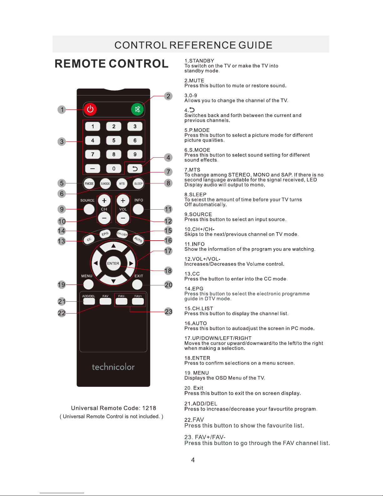
Model:TC2450A
Page 2
ENERGY
SAVING MODE
Page 3
Page 4
*
SAFETY PRECAUTION
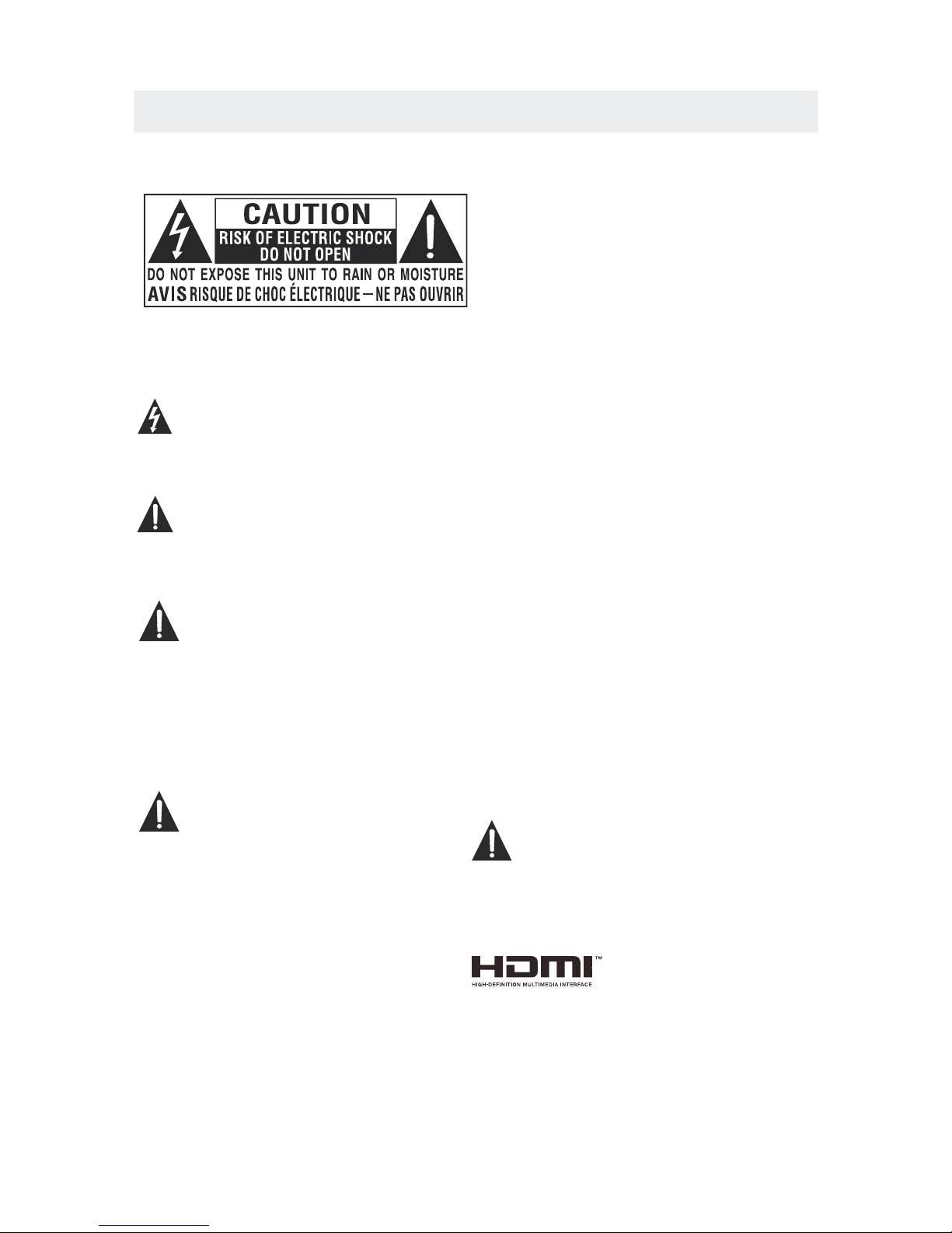
CAUTION
•
•
•
WARNING:
PLACEMENT INFORMATION
SAFETY INFORMATION
RATING PLATE LOCATION
FCC STATEMENTS
WARNING:
1
CAUTION MARKING WAS LOCATED AT THE REAR
OF THE APPARATUS.
WARNING: TO REDUCE THE RISK OF ELECTRIC
SHOCK,DO NOT REMOVE COVER(OR BACK)
NO USER SERVICEABLE PARTS INSIDE.
REFER SERVICING TO QUALIFIED SERVICE
PERSONNEL.
The lightning flash with arrowhead symbol,
within an equilateral triangle,is intended to
alert the user to the presence of uninsulated
“dangerous voltage”within the product's enclosure
that may beof sufficient magnitude to constitute a
risk of electric shock to persons.
The exclamation point within an equilateral
Triangle is intended to alert the user to
The presence of important operating and
maintenance (servicing) instructions in the literature
accompanying the appliance.
DANGER OF EXPLOSION IF BATTERY IS
INCORRECTLY REPLACED. REPLACE ONLY
WITH THE SAME OR EQUIVALENT TYPE.
USE OF CONTROLS OR ADJUSTMENTS OR
PERFORMANCE OF PROCEDURES OTHER
THAN THOSE SPECIFIED MAY RESULT IN
HAZARDOUS RADIATION EXPOSURE.
•
•
TO REDUCE THE RISK OF FIRE OR ELECTRIC
SHOCK, DO NOT EXPOSE THIS APPLIANCE TO
RAIN OR MOISTURE.
TO REVENT FIRE OR SHOCK HAZARD, DO NOT
EXPOSE THIS UNIT TO RAIN OR MOISTURE. DO
NOT PLACE OBJECTS FILLED WITH LIQUIDS ON
OR NEAR THIS UNIT.
SHOULD ANY TROUBLE OCCUR, DISCONNECT
THE AC POWER CORD AND REFER SERVICING
TO A QUALIFIED TECHNICIAN.
Do not use this unit in places that are extremely
hot, cold, dusty or humid.
Do not restrict the airflow of this unit by placing it
somewhere with poor airflow, by covering it with
a cloth, by placing it on bedding or carpeting.
When connecting or disconnecting the AC power
cord, grip the plug and not the cord itself. Pulling
the cord may damage it and create a hazard.
When you are not going to use the unit for a long
period of time, disconnect the AC power cord.
The rating plate is located on the rear of the unit.
NOTE: This unit has been tested and found to comply
with the limits for a Class B digital device, pursuant
to Part 15 of the FCC Rules. These limits are designed
to provide reasonable protection against harmful
interference in a residential installation.
This unit generates, uses and can radiate radio
frequency energy and, if not installed and used in
accordance with the instructions, may cause harmful
interference to radio communication. However, there
is no guarantee that interference will not occur in a
particular installation. If this unit does cause harmful
interference to radio or television reception, which
can be determined by turning the unit off and on, the
user is encouraged to try to correct the interference
by one or more of the following measures:
- Reorient or relocate the receiving antenna.
- Increase the separation between the unit and
receiver.
-Connect the unit into an outlet on a circuit different
from that to which the receiver is connected.
- Consult the dealer or an experienced radio/TV
technician for help.
Changes or modifications to this
unit not expressly approved by the party responsible
for compliance could void the user authority
to operate the unit.
•
•
•
•
“HDMI, the HDMI logo and High-Definition Multimedia
Interface are trademarks or registered trademarks of
HDMI Licensing LLC.”
Page 5
Energy saving mode
Page 6
ACCE SSO RIES
Please check and identif y the supplied accessories.
.. ... ... ... ... .... ... ... ... .... ... ... ... ... .... ... ... ... .... ... ... ... ... .... ... ... ... ....... ... ... ... .... ... ... .
.. ... ... ... ... .... ... ... ... .... ... ... ... ... .... ... ... ... .... ... ... ... ... .... ... ... ... ....... ... ... ... .... ..
GE TTING S TAR TE D
US INGTHER E MOT EC ONT RO L
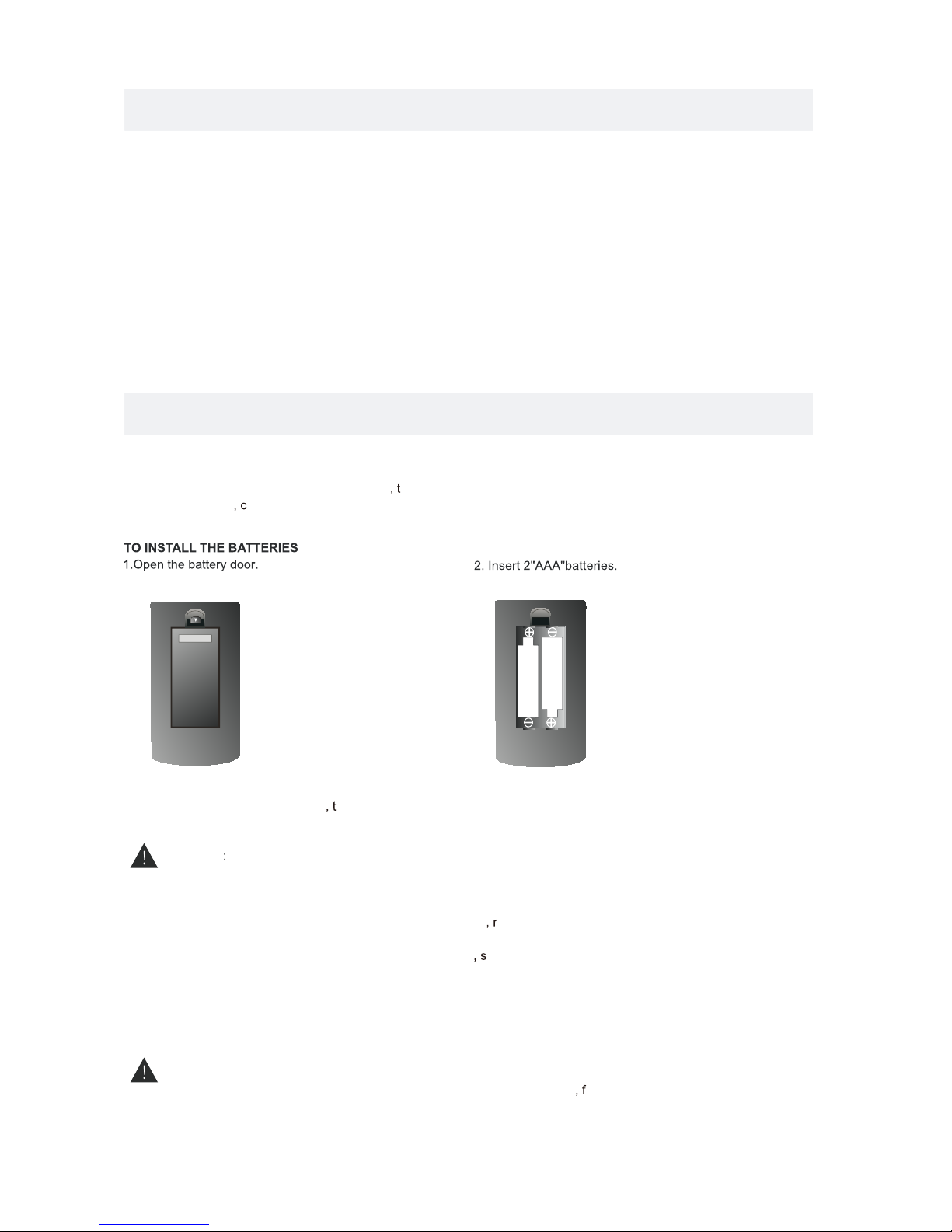
B ATT E RY RE P LAC E ME NT
C AUT ION
Da nge r of e xpl osio n if batter y is in cor rec tly r epl ace d.
NOT ES
WAR NING :
3
x 2
x 1
x 1
x 1
Remo te co ntr ol ....... ... ... ........ ... ... ........ ... ... ........ ... ... ........ ... ... ........ ... ... ........ ... ... ........ ... ... ..
Remo te co ntr ol
Batt ery (AA A)
Warr ant y Car d
Inst ruc tio n Man ual
·Poi nt th e rem ote c ont rol at the rem ote s ens or lo cat ed on t he unit.
·Whe n the re is a s tro ng am bie nt light sou rce
he per for man ce of t he in frared remote s ens or
·may b e deg rad ed
ausi ng un rel iab le op era tio n.
·The r eco mme nde d eff ect ive distan ce fo r rem ote o per ation is about 16 f eet ( 5 met ers ).
When t he ba tte rie s bec ome w eak
he ope rat ing d ist anc e of th e rem ote contro l is gr eat ly
redu ced a nd yo u wil l nee d to re pla ce the batte rie s.
·If th e rem ote c ont rol i s not going to be use d for a l ong t ime emov e the b att eri es to a voi d
dama ge ca use d by ba tte ry le aka ge corrosi on.
·Do no t mix o ld an d new b att eri es. Do not mix A LKA LIN E
tand ard ( CAR BON -ZI NC) o r
rech arg eab le (N ICK EL- CAD MIUM) batt eri es.
·Alw ays r emo ve ba tte rie s as soon as the y bec ome w eak .
·Wea k bat ter ies c an le ak and severely d ama ge th e rem ote c ont rol.
Do not d isp ose b att eri es in a f ire. Batte rie s may e xpl ode o r lea k.
Batt eri es sh all n ot be e xposed to exces siv e hea t suc h as su nsh ine
ire or t he li ke.
2B as e s ta n ds a n d 4 sc re w sba se s t an d
.. ... ... ... ... .... ... ... ... .... ... ... ... ... .... ... ... ... .... ... ... ... ... ..
x 1
.... ... ... ........ ... ... ........ ... ... ........ ... ... ........ ... ... ........ ... ... ........ ... ... ........ ... ... .......
Power adaptor ...........................................................................................................................................
x 1
Page 7
Page 8
CONTROL REFERENCE GUIDE
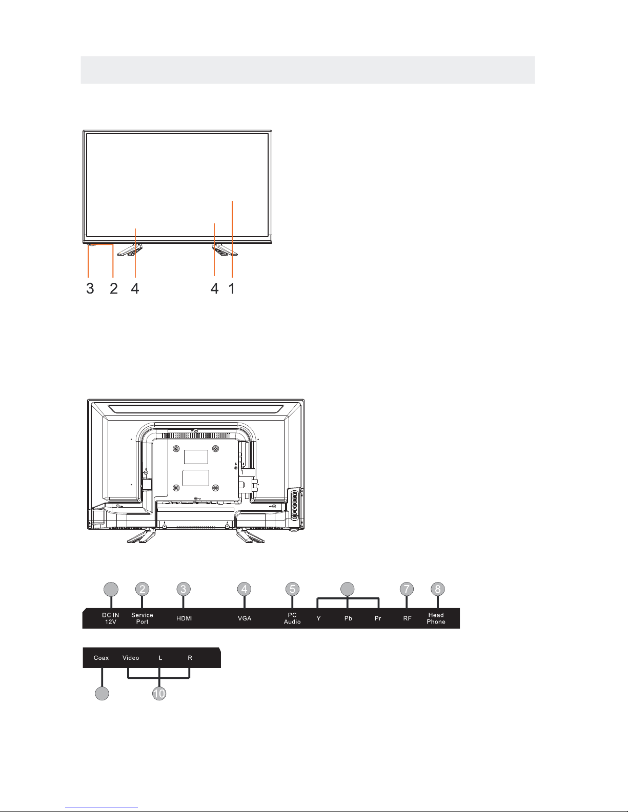
FRONT VIEW
5
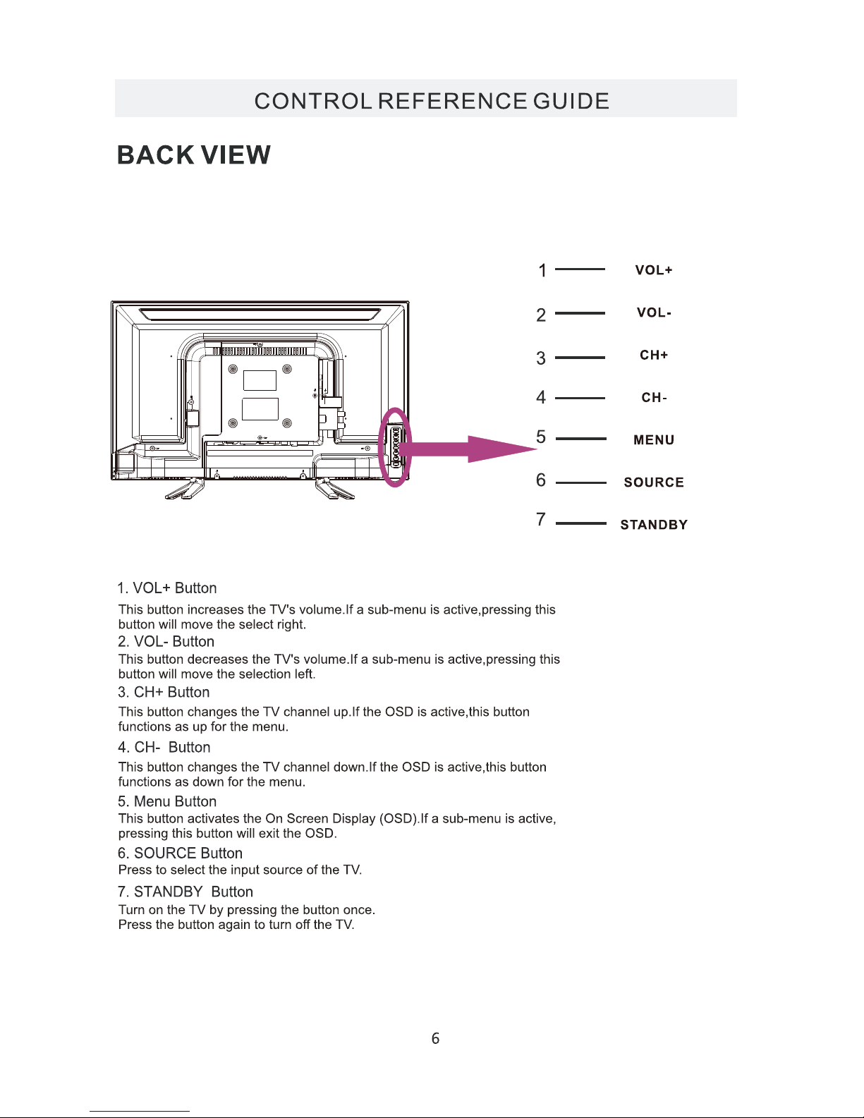
BACK VIEW
1.Color Screen
2.Remote Sensor
Do not block this sensor or the
remote control will not work.
3.Standby Indicator
Indicates whether the unit is ON
or in STANDBY (OFF) mode.
Light in red: The unit is in STANDBY.
Light in
blue:The unit is turned ON.
4. Speakers
1.DC IN
2.Service Port
3.HDMI IN Jacks
4.VGA IN Jack
5.PC ADUIO IN Jack
6.COMPONENT IN Jack
7.TV ANTENNA Terminal
8.Headphone Jack
9.Coax OUT Jack
10.AV IN Jack
9
6
1
Page 9
Page 10
CONNECTIONS
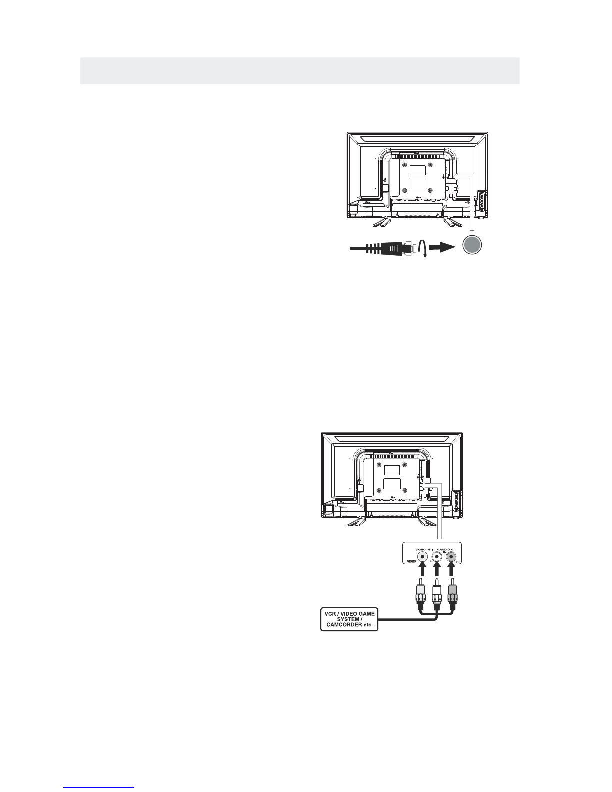
CONNECTING A TV ANTENNA / CABLE / SATELLITE
To view television channels correctly, a signal must
be received from one of the following sources:
- An indoor or outdoor aerial antenna
- A cable system
- A satellite system
For receiving over-the-air TV broadcasts, we
recommend that you use an external fixed antenna.
Should you require the use of a temporary antenna,
please ensure that you purchase an antenna with
sufficient ability to receive in weak signal areas.
Only when you are in close proximity to a transmitter
will a temporary antenna reproduce a signal as
strongly as a fixed antenna.
To connect to other equipment such as a VCR, camcorder, satellite system or cable, etc.
CONNECTING AN A/V DEVICE
NOTE
CONNECTING DEVICES WITH A COMPOSITE
VIDEO OUTPUT
Connecting to a VCR / Video Game System / Camcorder
AUDIOVIDEO OUT
NOTE
To connect A/V devices such as a VCR, video game system or camcorder.
Connect the AUDIO / VIDEO cable (not included) as shown.
Make sure you connect the cable from the other equipment (and) to this unit
1P.lease refer to the user manual
.
for the other equipment for
more information.
Satellite, cable or TV antenna
cable to TV ANTENNA
terminal (cable not included)
7
(AV in)
2. Composite video input
(shared with component)
To AUDIO / VIDEO
IN jacks
To AUDIO / VIDEO
OUT jacks
YELLO W
WHITERED
Page 11

CONNECTIONS
CONNECTING A HIGH-DEFINITION (HD) SOURCE USINGCONNECTION
NOTE
COMPONENT
High-Definition (HD) Devices with component video output must be connected to the Yinput.
Connect the component video cable and audio cable (not included) as shown.
Make sure you connect the component video cable and audio cable from the other equipment
When connecting a DVD player to the television,
the picture resolution is solely dependent upon
the resolution supported by the DVD player attached.
DVD player resolutions vary from 480i to 1080i.
and this television can support DVD players up to
a maximum resolution of 1080i.
PbPr
* May require a subscription
for receiving HD channels,
check with your cable/satellite
service provider for details.
To COMPONENT
VIDEO OUT jacks
CONNECTING A HIGH-DEFINITION (HD) SOURCE USING HDMI CONNECTION
HDMI (High Definition Multimedia Interface) supports both video and audio on a single digital connection
for use with DVD players, DTV, set-topboxes and other digital AV devices. HDMI was developed to provide
the technologies of High Bandwidth Digital Content Protection (HDCP) as well as Digital Visual Interface
(DVI) in one specification. HDCP is used to protect digital content transmitted and received by
DVI-compliant or HDMIcompliant displays.
HDMI has the capability to support standard, enhanced or high-definition video plus standard to
multi-channel surround-sound audio. HDMI features include uncompressed digital video, a bandwidth of
up to 2.2 gigabytes per second (with HDTV signals), one connector (instead of several cables and
connectors), and communication between the AV source and AV devices such as DTVs.
To HDMI
IN jack
To HDMI
jackOUT
To COMPONENT
VIDEO IN jacks
AUDIO IN jacks
To COMPONENT AUDIO
OUT jacks
Connect the HDMI cable (not included) as
shown:
Make sure you connect the cable from the
source equipment () to this unit
().
HDMI OUT
HDMI IN
HDMI CABLE
(NOT INCLUDED)
(COMPONENT OUT and AUDIO OUT)to the unit COMPONENT IN.
COMPONENT IN
8
To COMPONENT
Page 12

CONNECTIONS
CONNECTING A
AUDIO - PC OUT
VGAAUDIO - PC IN
PC
VGA
Connect the 15-pin D-SUB PC/VGA connector
from your computer to the 15-pin D-SUB PC/VGA
input on this unit using a monitor cable and an
audio cable (not included) as shown.
Make sure you connect the cable from the computer
(and) to this unit
(and).
TO PC Connector
TO AUDIO OUT jacks
NOTE
•Insert the power plug fully into the socket outlet
If the power plug is looseit could generate heat and
cause fire
Do not touch the power plug with a wet hand
This may cause electrical shock
Do not use any power cord other than that provided
with this TVThis may cause fire or electrical shock
Do not damage the power cord
A damaged cord may cause fire or electrical shock
• Do not move the TV with the cord plugged in the
socket outlet.
• Do not place a heavy object on the cord or place
the cord near a high-temperature object.
• Do not twist the cord, bend it excessively, or stretch it.
• Do not pull on the cord. Hold onto the power plug body when disconnecting cord.
• Do not use a damaged power plug or socket outlet.
.
(,
.)
.
.
•
•
•
connected to prevent electrical shock.
Ensure that the power plug is easily accessible.
Ensure the earth pin on the power plug is securely
•
•
9
.)
Page 13

Page 14

4”
4”
Page 15

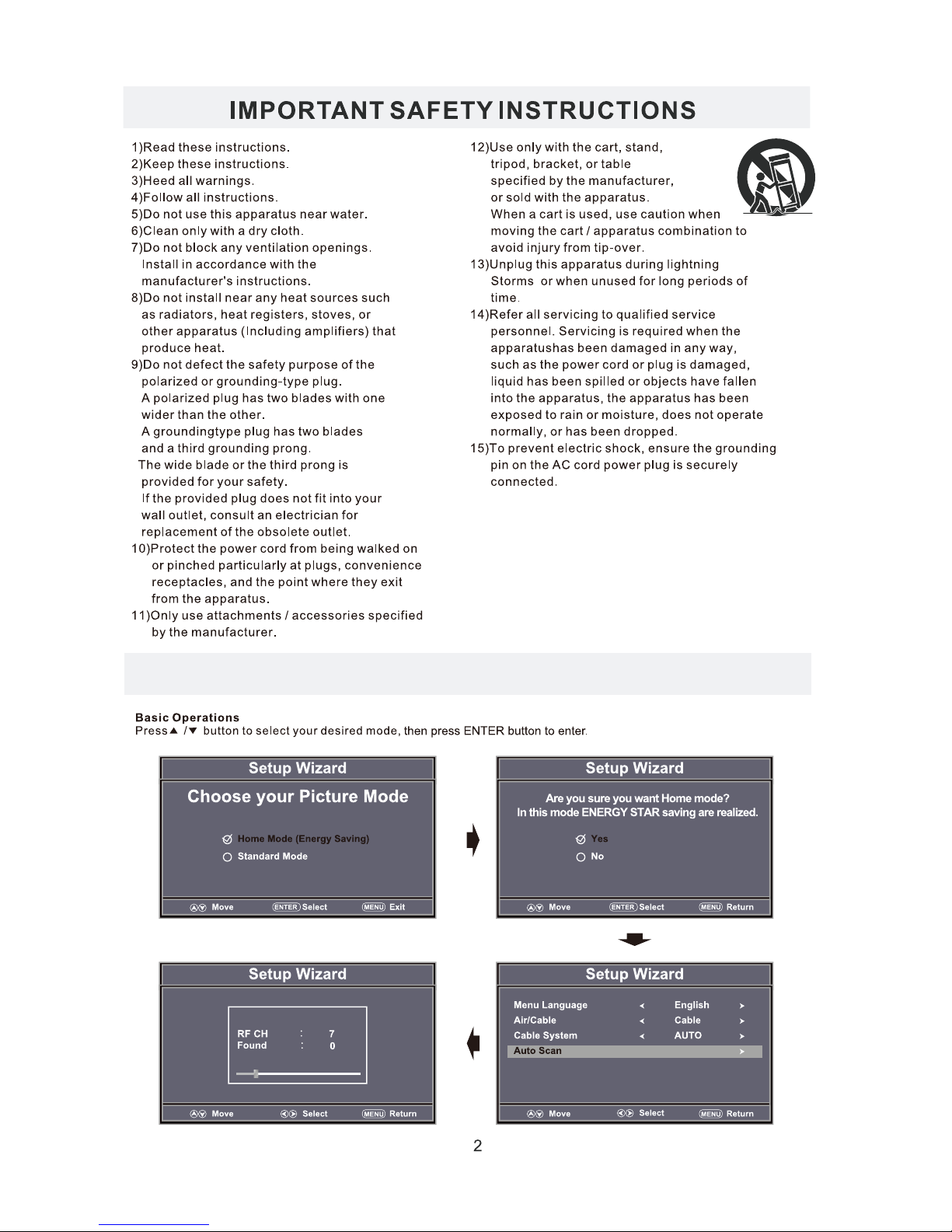
Please Run
Channel Auto Scan
INPUT SOURCE
TV
Component
HDMI
VGA
AV
Page 16

Good
Good
Page 17

temp.
Page 18

TV SETUP
15
Page 19

TV SETUP
16
Page 20

TV SETUP
17
Page 21

Clock 2012/11/20 04:08 PM
Clock 2012/11/20 04:08 PM
Clock 2012/11/20 04:08 PM
Page 22

TV SETUP
19
Auto adjust success
Adjust
Page 23

TV SETUP
20
Auto adjust success
Adjust
Auto adjust success
Adjust
Auto adjust success Auto adjust success
Adjust
Page 24

TV SETUP
21
Page 25

22
Page 26
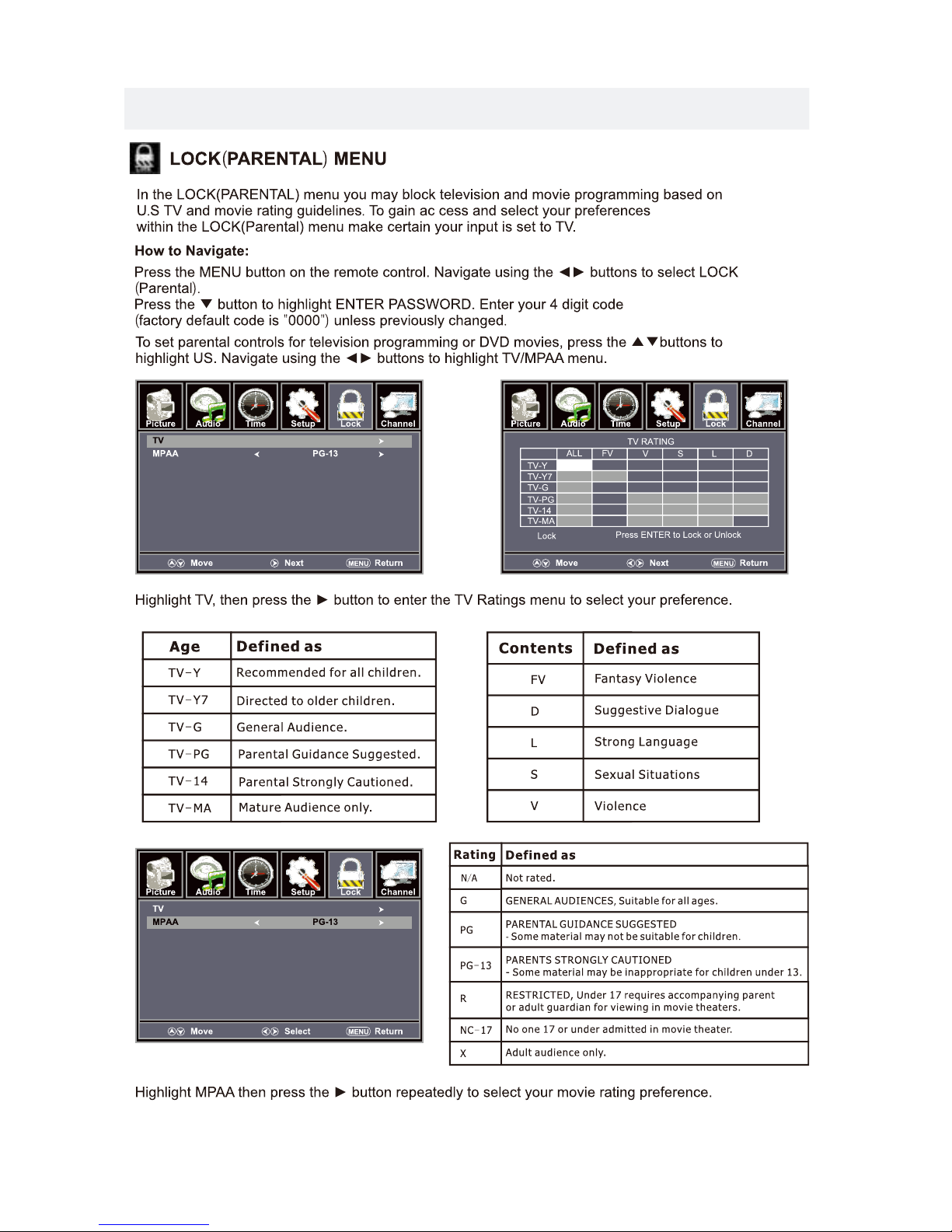
TV SETUP
23
Page 27

TV SETUP
24
Page 28

TV SETUP
25
Page 29

26
Page 30

27
5
Page 31

28
Page 32

SPECIFICATION
This manual is only for your reference.
Specifications are subject to update without prior notice.
29
TV
Panel Type
24 inches
Diagonal Size
Screen Format 16 9:
Color System
ATSC/QAM/NTSC
Model Description
Panel
Resolution 1366 x 768
View Angle
Response Time
Contrast
Brightness
Maximum Color
180 cd/m²
3000:1
16.7M colors
Sound Output
RF Input 75 ohm external terminal
HDMI Input
Video 480i 480p 720p 1080i, 1080p.: , , ,
Audio Two channel linear PCM 32 44 1 and 48kHz 16 20 and 24 bits: , . , ,
PC RGB Input-
D sub 15pinG 0 7Vp p 75ohms: . - ,
B 0 7Vp p 75ohms: . - ,
R 0 7Vp p 75ohms: . - ,
Power Requirement
Input /
Output
Jacks
Systems
Power
Sound System
M
Audio System
BTSC
L/R Speaker:3W+3W
Composite Video Input
Component Y Pb Pr Input/
Sound Input
PC AUDIO: For PC RGB Audio input
500mV rms, Impedance: 20k ohms
RCA
Y: 1.0 Vp-p, 75oh ms, 0. 3V neg ati ve syn c
Pb: 0.7V p-p , 75oh ms
Pr : 0.7Vp-p, 75 ohm s
DC 12/3A
176( H)/ 176 (V)
36 W
1. 0 Vp- p, 75ohms RCA
AV AUDIO: For CVBS/COMPONENT Audio input
Rated Power Consumption
8 .5ms
LED Panel
Page 33

SYMPTOM CAUSE AND REMEDY( )
TV
Bad
Picture
(snow,
multiple
images
distortion,blurry)
No sound.
Black
and
White
picture.
No picture or sound.
Coloredpatches of
picture.
Panel function key does
not respond correctly.
Check the location of the antenna and adjust it if necessary.
Make sure the antenna cable is firmly connected.
Make sure all input cables are firmly connected.
Increase the volume.
Check the PICTURE setting within the PICTURE menu.
Make sure the unit is plugged in and turned on.
Make sure that the ATV mode is selected.
Try a new channel to check for possible station trouble.
Make sure the antenna is connected properly.
Increase the volume.
Make sure all cables are firmly connected.
Check for local interference.
Make sure there are no unshielded electrical devices nearby
that are causing interference.
Turn the TV off for 30 minutes, then try it again.
Under the influence of electrostatic phenomenon, the product
may malfunction and require usertopowerreset.
Unplug and re-plug the AC power cord.
TROUBLESHOOTING GUIDE
Check to make sure the program you are watching is broadcast
in Color and not Black & White.
Check
whether the mute function has been activated on the
Remote Control.
The display monitor's
panel goes hot.
LED TV takes inside lighten phosphor. It may increase the
temperature of the screen in some occasions. It's not a defect.
Unusual dots
Black dots and Bright points may appear on the LED screen.
This is a structural property of the LED panel and is not a defect.
Stripes on screen
Adjust the impulse phase may decrease stripes. RGB in
The top of the monitor
It may occur during long-time working. It's not a defect.
gets hot
.
Make sure the antenna or audio/video source device is
working properly.
Unable to select a
certain channel.
The channel may be sk ipped. Choose this channel by
directly selecting the buttons from the remote control.
Disorder display
at power on.
This may be caused because of a very short interval
between POWER OFF and ON.
Unplug the power and restart.
30
 Loading...