

Page 1
© 2016 Technicolor. All Rights reserved
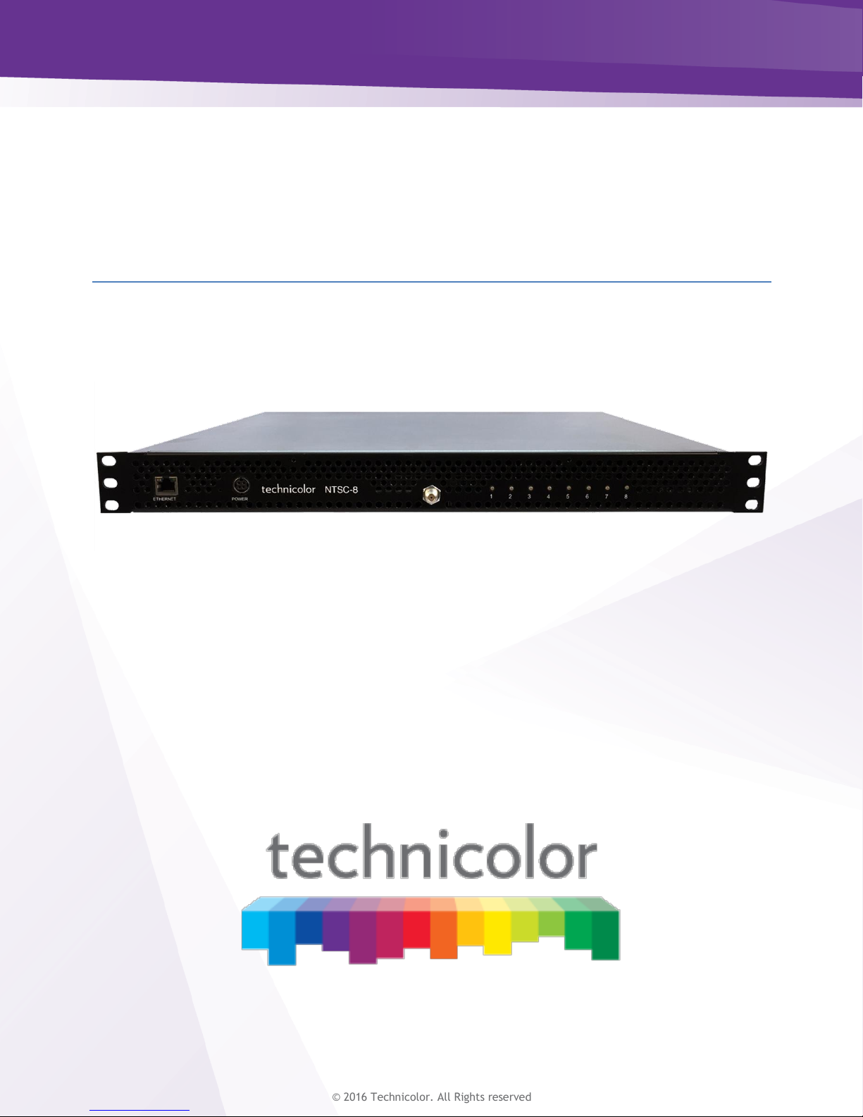
Technicolor NTSC-8
User’s Manual
Page 2

w w w . t e c h n i c o l o r . c o m / m c s
Page 1
Table of Contents
1 Introduction ................................................................................................................................. 4
2 Front Panel Connections ............................................................................................................. 4
3 Power Supply .............................................................................................................................. 5
4 Physical Connections .................................................................................................................. 6
5 COM46 Software Requirements and Setup ................................................................................ 8
6 NTSC-8 Setup ............................................................................................................................. 9
6.1 Setting up Multiple Chassis....................................................................................................... 10
6.2 Setting the Modulator Output Channels .................................................................................... 13
6.3 Using Internal Attenuation ........................................................................................................ 15
6.4 Carrier ON ................................................................................................................................. 17
6.5 Sharpness ................................................................................................................................... 17
6.6 Reset .......................................................................................................................................... 17
6.7 Audio Level ............................................................................................................................... 18
6.8 Aspect Ratio .............................................................................................................................. 18
6.9 Verification of Streams ............................................................................................................. 18
7 Software Upgrade ...................................................................................................................... 19
8 Status Lights .............................................................................................................................. 20
Page 3

w w w . t e c h n i c o l o r . c o m / m c s
Page 2
Table of Figures
FIGURE 1 - NTSC-8 FRONT PANEL ...................................................................................................... 4
FIGURE 2 - POWER SUPPLY .................................................................................................................. 5
FIGURE 3 - PHYSICAL CONNECTIONS ................................................................................................... 6
FIGURE 4 - POWER SUPPLY CONNECTIONS .......................................................................................... 7
FIGURE 5 - COM46 PAIRING INFO PAGE ............................................................................................. 8
FIGURE 6 - COM46 USER CONFIG ....................................................................................................... 8
FIGURE 7 - COM46 MAIN INTERFACE PAGE........................................................................................ 9
FIGURE 8 - COM46 NTSC TAB ........................................................................................................... 9
FIGURE 9 NTSC-8 MODULATOR IP ................................................................................................... 10
FIGURE 10 - ENTER ALTERNATE IP ADDRESS .................................................................................... 11
FIGURE 11 - ALTIP ............................................................................................................................. 11
FIGURE 12 – CHASSIS DIPSWITCH ...................................................................................................... 12
FIGURE 13 - DIPSWITCH SETTINGS..................................................................................................... 12
FIGURE 14 - OUTPUT CHANNEL SETTINGS ......................................................................................... 13
FIGURE 15 - STATUS PAGE SHOWING SET CHANNELS ....................................................................... 13
FIGURE 16 - CHANGING OUTPUT CHANNEL BY MODULATOR ............................................................ 14
FIGURE 17 - CHANNELS SET IN STATUS TABLE ................................................................................. 15
FIGURE 18 - SET ATTENUATION IN ALL MODULATORS ...................................................................... 15
FIGURE 19 CHANGING ATTENUATION ON A SINGLE MODULATOR ..................................................... 16
FIGURE 20 - CARRIER ON/OFF ............................................................................................................ 17
FIGURE 21 - BYTESRECIEVED ............................................................................................................ 18
FIGURE 22 - COM46 TFTP FEATURE ON PAIRING INFO PAGE .......................................................... 19
FIGURE 23 - NTSC-8 SOFTWARE UPDATE ......................................................................................... 19
FIGURE 24 - SOFTWARE VERSION IN STATUS TABLE ......................................................................... 20
FIGURE 25 - LED STATUS DEFINITIONS............................................................................................. 20
Page 4

w w w . t e c h n i c o l o r . c o m / m c s
Page 3
REVISION RECORD
Revision
Date
Revision Editor
Revision Description
1
11/3/16
Angelo Peruch
Final Draft Approved
1.1
11/10/16
Angelo Peruch
Revised chassis table
Page 5
w w w . t e c h n i c o l o r . c o m / m c s
Page 4
1 Introduction
The NTSC-8 accepts encrypted video signals from a COM46 card via Ethernet, and modulates
those eight signals as analog NTSC, standard definition, unencrypted RF channels. One NTSC-8
will modulate eight channels from one COM46 card.
Connecting multiple NTSC-8s to a COM360 chassis using a Gigabit Ethernet switch (not included)
The system offers all the advantages of a COM2000 system including remote management, and is
expandable to high definition for cost effective upgrades in the future.
System requires one RU of rack space.
Ventilation fans are rear mounted. The front and rear areas of the NTSC-8 should be kept clear to
ensure good airflow.
Included in the box is the NTSC-8 unit and power supply.
Note: Technicolor only supports NTSC-8 installations when interfaced to COM46 cards in a
COM360 chassis.
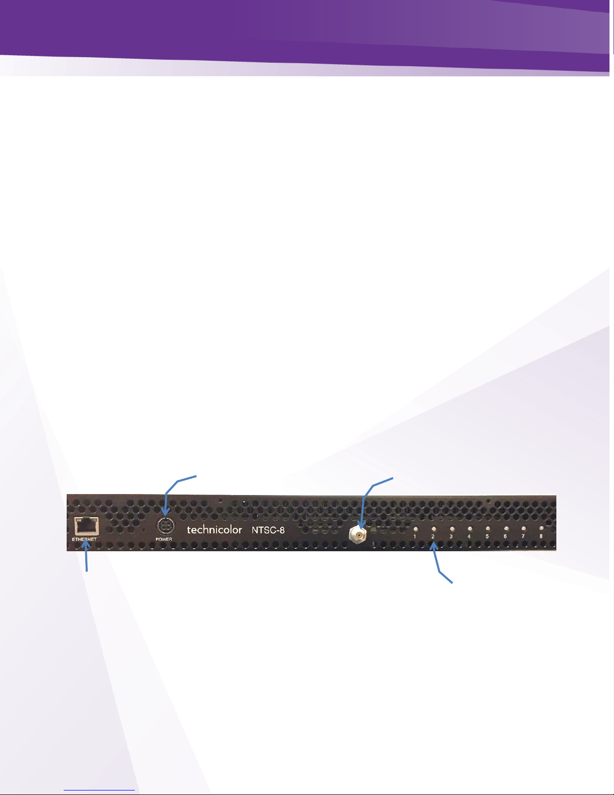
2 Front Panel Connections
All connections to the NTSC-8 are on the front panel as shown in Figure one above.
Figure 1 - NTSC-8 Front Panel
Ethernet Port
Power Input Port
RF Connector
Status Lights
Page 6

w w w . t e c h n i c o l o r . c o m / m c s
Page 5
3 Power Supply
An external AC adaptor is included with the NTSC-8. The power adapter has a locking connector
that clicks when properly seated as shown below in Figure 2.
Figure 2 - Power Supply
Page 7

w w w . t e c h n i c o l o r . c o m / m c s
Page 6
4 Physical Connections
Figure 3 below details the connection of two NTSC-8 units connected to a COM2000 system. If
more than one unit is to be connected, a gigabit Ethernet switch (not included) is required between
a chassis GbE port and the NTSC-8s.
Connect remote management directly to an unused COM360 GbE port or to the GiGe switch.
To RF Distribution
Remote
Management
Device
Figure 3 - Physical Connections
Page 8

w w w . t e c h n i c o l o r . c o m / m c s
Page 7
Connect the Power Cord
Carefully insert the power cord into the Power port on the NTSC-8 as shown in Figure 4. When
properly seated in the power port the plug will snap into place with an audible click. To remove,
firmly pull back on the cover and remove the plug from the power port.
Figure 4 - Power Supply Connections
Page 9

w w w . t e c h n i c o l o r . c o m / m c s
Page 8
5 COM46 Software Requirements and Setup
5.1 Software Requirements
COM46 cards need to be running software to version ST03.03.15 or later. You can verify software
version from the COM46 Pairing information page as shown below in Figure 5.
Figure 5 - COM46 Pairing Info Page
See COM2000 integrators manual or consult with your distributor if you need assistance upgrading
software.
5.2 COM46 Setup
Each COM46 card will stream eight channels to the NTSC-8. You will need to enter the IP
address of the first NTSC-8 modulator in the COM46 advanced edit page as shown below in
Figure 6. By default, the NTSC-8 IP addresses are set to 192.168.5.1 / 8.
Enter the IP address of the first modulator in the NTSC-8 in the NTSC8_IP field. Click Submit
Repeat in each COM46 card that is associated with a NTSC-8 unit.
(See section 5.1 below for setting up the NTSC-8).
Figure 6 - COM46 User Config
Once you have all the NTSC-8s and COM46s set up retune the channels or restart the COM 46
cards.
Enter NTSC-8 modulator 1 IP address
Submit
COM46 Software Version
Page 10

w w w . t e c h n i c o l o r . c o m / m c s
Page 9
6 NTSC-8 Setup
To access the NTSC user interface click on the NTSC tab as shown below in Figure 7 and Figure 8.
Note the box to the right of each field in the Control section. Checking this box will apply that
setting to all modulators in the NTSC-8.
Figure 7 - COM46 Main Interface Page
Figure 8 - COM46 NTSC Tab
Click box to apply setting to all
modulators
Page 11

w w w . t e c h n i c o l o r . c o m / m c s
Page 10
Each controllable option in the interface is covered in the following sections.
Control Feature Definitions
channel
NTSC channel output
attenuation
Attenuates the RF output up to 10dBmV. Default value is 0
carrier on
Enter a 0 in this field to shut off the carrier
reset
Enter a 1 in this field to reset the device
sharpness
N/A
audio level
Adjusts the audio volume (a reset is required for this setting to take affect)
aspect ratio
0 = 4X3 1= 16X9 (a reset is required for this setting to take affect)
alternate Ip
Sets an alternate IP address for each modulator
tftpIP
For software upgrade enter the IP of the COM46 card being used at a TFTP server
tftpFilename
For software upgrade enter the software filename uploaded to the COM46
6.1 Setting up Multiple Chassis
Each channel or modulator within a NTSC-8 is assigned an IP address as shown below in Figure 9 .
By default modulator one in chassis zero is 192.168.5.1.
Figure 9 NTSC-8 Modulator IP
When multiple chassis are used, the default IP for each modulator needs to be set.
There are two options for setting the IP addresses.
Page 12

w w w . t e c h n i c o l o r . c o m / m c s
Page 11
Option One: (recommended) Set Alternate IP address in NTSC-8 User Interface
Since the IP address of the first modulator is set to 192.168.5.1 connecting two NTSC-8s in default
configuration will result in an IP conflict.
To change the IP address connect only additional units, one at a time to the COM2000. For this
example, we will continue with the 192.168.5.XXX IP scheme and assign 192.168.5.9/16 to the
second NTSC-8.
In the Control section of the NTSC user interface, enter an IP address in the alternateIp field as
shown in below in Figure 10.
Figure 10 - Enter Alternate IP Address
Check the box to the right of the field to apply this setting to all modulators and click Submit.
You will see the new settings in the altIp column of the Status display as show in Figure 11 below.
Figure 11 - altIp
Label the NTSC-8 with the new IP address and repeat this procedure for each chassis. These
settings are stored in non-volatile memory and is retained by the unit after powering off.
Enter IP and check box
New Alternate IPs
Submit
Page 13

w w w . t e c h n i c o l o r . c o m / m c s
Page 12
Option Two: Dipswitch Settings
Each NTSC-8 chassis can be set up using the internal dipswitches on the main board as shown
below in Figure 12. To access the dipswitches, remove the top cover of the chassis. A #10 hex
driver is required to remove the 11 chassis screws. Set the chassis number using the table in Figure
13.
Figure 12 – Chassis Dipswitch
Chassis ID
Switch 1
Switch 2
Switch 3
Switch 4
Default IP MOD 1
0
DOWN
DOWN
DOWN
DOWN
192.168.5.1/8
1
UP
DOWN
DOWN
DOWN
192.168.5.9/16
2
DOWN
UP
DOWN
DOWN
192.168.5.17/24
3
UP
UP
DOWN
DOWN
192.168.5.25/32
4
DOWN
DOWN
UP
DOWN
192.168.5.33/40
5
UP
DOWN
UP
DOWN
192.168.5.41/48
6
DOWN
UP
UP
DOWN
192.168.5.49/56
7
UP
UP
UP
DOWN
192.168.5.57/64
8
DOWN
DOWN
DOWN
UP
192.168.5.65/72
9
UP
DOWN
DOWN
UP
192.168.5.73/80
10
DOWN
UP
DOWN
UP
192.168.5.81/88
11
UP
UP
DOWN
UP
192.168.5.89/96
12
DOWN
DOWN
UP
UP
192.168.5.97/104
13
UP
DOWN
UP
UP
192.168.5.105/112
14
DOWN
UP
UP
UP
192.168.5.113/120
Figure 13 - Dipswitch Settings
1
2 3
4
Page 14

w w w . t e c h n i c o l o r . c o m / m c s
Page 13
Once you have set the NTCS-8 IP addresses, connect all units to the COM360 Chassis GbE
Ethernet port via a Gigabit Ethernet switch. If installing only one NTSC-8 unit, it can be connected
directly to one of the GbE ports on the COM360.
6.2 Setting the Modulator Output Channels
Set the RF output channel for the modulators using the channel field in the Control section. To set
all channels in the NTSC-8 to contiguous channels you can enter the first channel in the field and
check the box to the right as shown in Figure 14. In the example below, we will set channel outputs
for as 2-9. Channels set in numerical order. NTSC-8 supports RF channels 2-107.
Figure 14 - Output Channel Settings
As shown below in Figure 15 the Status page now displays the output channels 2-9 in the channel
column.
Figure 15 - Status Page Showing Set Channels
Output channels
Submit
Enter output channel for modulator 1
And click box to apply to all modulators
Page 15

w w w . t e c h n i c o l o r . c o m / m c s
Page 14
Change channels on individual modulators by entering the IP address of the modulator in the
NTSC-8 Modulator field as shown in Figure 16 below. In this example, we will change the output
channel of modulator 6 (slot 5) to channel 14, modulator 7 to 15 and modulator 8 to 16.
Enter the IP address of modulator 6; it will now display at the top of the status table.
Figure 16 - Changing Output Channel by Modulator
Enter the desired channel in the field. Do not check the box as you only want to change that
modulator. Click submit
Repeat this process until RF outputs are set.
Enter modulator IP
Modulator displayed
Enter desired output channel for modulator
Submit
Submit
Page 16

w w w . t e c h n i c o l o r . c o m / m c s
Page 15
Figure 17 below shows we have change the output channels of modulators 6, 7, and 8 to 14, 15 and
16.
Figure 17 - Channels Set in Status Table
6.3 Using Internal Attenuation
The NTSC-8 will output approximately 25dBmV from the internally combined eight modulators.
Attenuation may be set in all, or individual modulators to adjust the output power as necessary.
The default attenuation is set to 0. Maximum attenuation is 10dB.
To set attenuation for all modulators in a NTSC-8 enter the IP address of the first modulator in the
NTSC-8 Modulator field and click Submit.
In this example, we will attenuate all modulators 5 db. Enter the attenuation value in the
attenuation field and check the box as shown below in Figure 18. Click submit.
Figure 18 - Set Attenuation in all Modulators
Output channels changed
Enter attenuation value and check the box
Submit
Page 17

w w w . t e c h n i c o l o r . c o m / m c s
Page 16
The status table will reflect the entry in the attenuation column.
To change the attenuation level on a single modulator enter the IP address of the modulator in the
NTSC-8 Modulator field and click Submit. Enter the attenuation value in the attenuation field (do
not check the box) and click submit. In this example, we changed the attenuation value of
modulator two (slot1) to 8 dB.
The attenuation value for modulator 2 has been set to 8dB as shown in Figure 19.
Figure 19 Changing Attenuation on a Single Modulator
Attenuation level
Enter modulator IP address
Submit
Attenuation level
Enter attenuation level for modulator
Do not check box
Submit
Page 18

w w w . t e c h n i c o l o r . c o m / m c s
Page 17
6.4 Carrier ON
The carrierOn field activates the RF output of each modulator. Entering a 0 in the field deactivates
the modulator. Follow the same steps as above to turn all or individual carriers on or off. In the
example shown in Figure 20 we have turned on all the carriers in the NTSC-8.
Figure 20 - Carrier on/off
6.5 Sharpness
This control is not active
6.6 Reset
Entering a 1 in the reset field and clicking submit will restart the NTSC-8. Upon reset, the status
table will disappear. Reset is complete in about 2 minutes.
Enter 1 to turn carrier on
Check box to apply to all modulators
Submit
Page 19

w w w . t e c h n i c o l o r . c o m / m c s
Page 18
6.7 Audio Level
The audio level allows adjustment of volume levels from channel to channel. Default is 0.
Entering a value between 1-10 will reduce the volume on a selected modulator. Once a value is
entered, a reset of the NTSC is required. (See section 5.6)
6.8 Aspect Ratio
The aspect ratio of the modulator is adjustable between 4x3 and 16x9 ratios. The default is 1 =
16x9. If 4x3 aspect ratio is required, enter a 0 in the field, check the box for all modulators and
click submit. This adjustment requires a reset of the NTSC-8. (See section 5.6)
6.9 Verification of Streams
As shown in Figure 21 the bytesRecieved column will continually grow as the COM46 streams to
the NTSC-8. The display is static so you will need to refresh the screen to see the value change.
Refresh the screen by clicking on the Submit button in the NTSC8 Modulator section. Each time
the screen refreshes you will see the bytesRecieved column change. If the value is not changing,
the NTSC-8 is not receiving data from the COM46. Check your connections and verify you have
entered the NTSC-8 IP address in the COM46 as described in section 4.2. Then retune the channels
from the tune all screen or reboot the COM46.
Figure 21 - bytesRecieved
When the NTSC-8 is receiving streams, the status lights will illuminate solid green. For more
status light information, refer to section 5.10.
Page 20

w w w . t e c h n i c o l o r . c o m / m c s
Page 19
7 Software Upgrade
If the NTSC-8 requires a software upgrade, the COM46 TFTP feature will facilitate the process.
Upload the software to the COM46 Pairing Info page as described in the COM46 Integrators
Manual. Copy the file name from the COM46 Software upgrade page as shown below in Figure 22.
Figure 22 - COM46 TFTP Feature on Pairing Info Page
Navigate to the NTSC tab. Paste the file name into the tftpFilename field in the control section and
enter the IP address of the COM46 card as shown below in Figure 23. Click submit.
Figure 23 - NTSC-8 Software Update
Upload software and copy filename
Paste filename
Enter IP address of COM46 and check box to upgrade all modulators
Submit
Page 21

w w w . t e c h n i c o l o r . c o m / m c s
Page 20
The status lights will flash yellow during software load and red/green during software upgrade. Do
not power off NTSC-8 during this process. Lights will resume to solid green when complete. New
software version is displayed in the swVersion column of the NTSC-8 status table as shown below
in Figure 24.
Figure 24 - Software Version in Status Table
8 Status Lights
A set of eight lights on the front panel represents each modulator on the NTSC. Figure 25 below
defines the status of the lights displayed.
LED State
Mode
Description
Solid Green
Normal
Normal Function
Flashing
Yellow
Downloading
During tftp file download (usually for SW update), LED
blinks yellow. 200ms on, 200 ms off
Flashing
red/green
Software update
Do not restart unit, unit automatically restarts after SW
update. LED will return to green after reboot.
Flashing Red
No Physical
connections
No Ethernet link with COM2000 unit
Flashing
Red/Yellow
10 MBPS link
No 100MBPS link established
Solid Red
Trouble
Undefined Problem
Figure 25 - LED Status Definitions
Software version
 Loading...