

Page 1
SETUP AND USER GUIDE
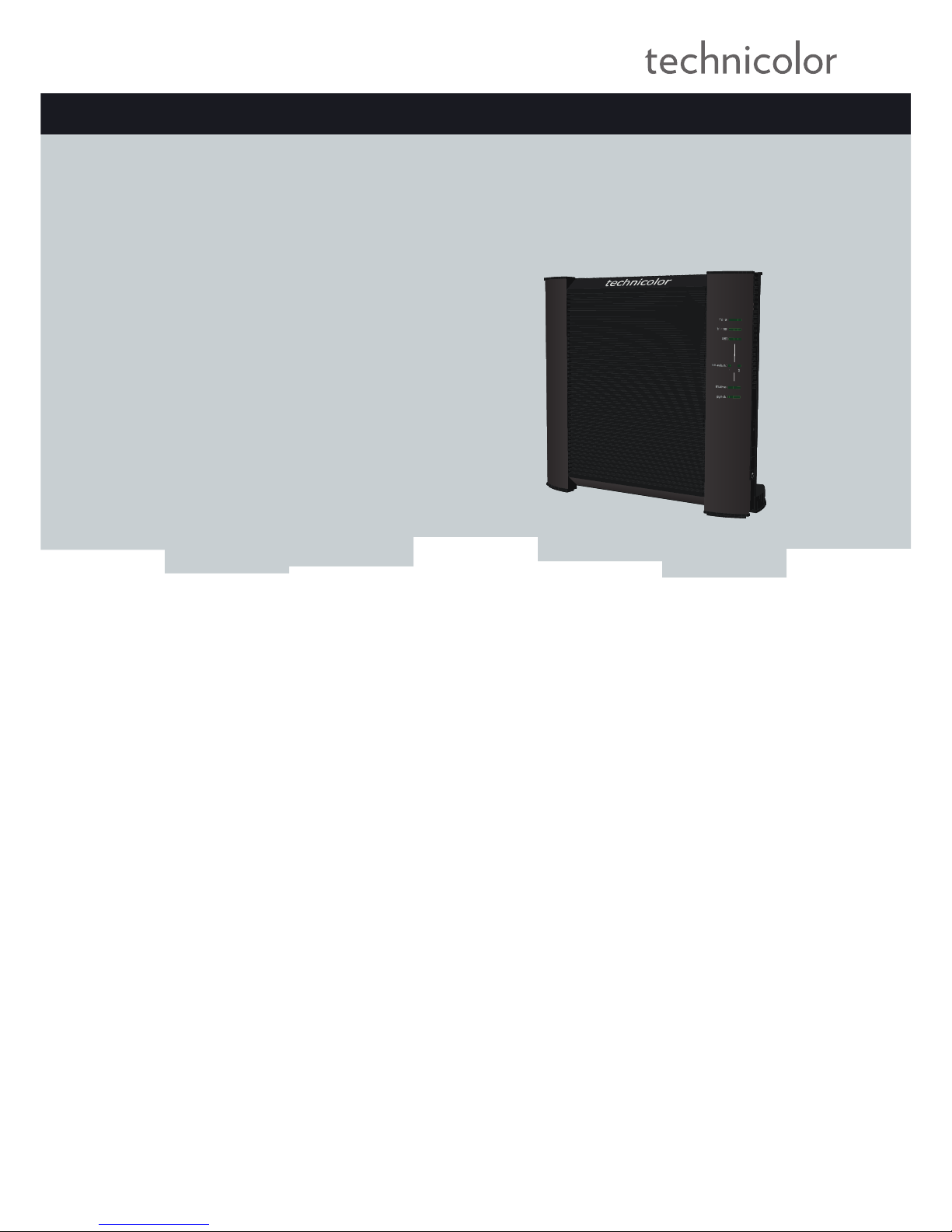
MediaAccess TG650s
Page 2

Page 3

SETUP AND USER GUIDE
MediaAccess TG650s
Page 4

Copyright
Copyright ©1999-2012 Technicolor. All rights reserved.
Distribution and copying of this document, use and communication of its contents is not permitted without written authorization from
Technicolor. The content of this document is furnished for informational use only, may be subject to change without notice, and should not
be construed as a commitment by Technicolor. Technicolor assumes no responsibility or liability for any errors or inaccuracies that may
appear in this document.
Technicolor Delivery Technologies Belgium NV
Prins Boudewijnlaan, 47
2650 Edegem
Belgium
http://www.technicolor.com
Trademarks
The following trademarks may be used in this document:
AutoWAN sensing™ is a trademark of Technicolor.
Adobe®, the Adobe logo, Acrobat and Acrobat Reader are trademarks or registered trademarks of Adobe Systems, Incorporated,
registered in the United States and/or other countries.
Apple® and Mac OS® are registered trademarks of Apple Computer, Incorporated, registered in the United States and other countries.
Bluetooth® word mark and logos are owned by the Bluetooth SIG, Inc.
DECT™ is a trademark of ETSI.
DLNA® is a registered trademark, DLNA disc logo is a service mark, and DLNA Certified is a trademark of the Digital Living Network
Alliance. Digital Living Network Alliance is a service mark of the Digital Living Network Alliance.
Ethernet™ is a trademark of Xerox Corporation.
Microsoft®, MS-DOS®, Windows®, Windows NT® and Windows Vista® are either registered trademarks or trademarks of Microsoft
Corporation in the United States and/or other countries.
UNIX® is a registered trademark of UNIX System Laboratories, Incorporated.
UPnP™ is a certification mark of the UPnP™ Implementers Corporation.
Wi-Fi®, WMM® and the Wi-Fi logo are registered trademarks of the Wi-Fi Alliance®. Wi-Fi CERTIFIED, Wi-Fi ZONE, Wi-Fi
Protected Access, Wi-Fi Multimedia, Wi-Fi Protected Setup, WPA, WPA2 and their respective logos are trademarks of the Wi-Fi Alliance®.
Other brands and product names may be trademarks or registered trademarks of their respective holders. All other logos, trademarks and
service marks are the property of their respective owners, where marked or not.
Document Information
Status: v1.0 (April 2012)
Reference: DMS-CTC-20111123-0002
Short Title: Setup and User Guide MediaAccess TG650s R8.4.x
Page 5

i
CONTENTS
DMS-CTC-20111123-0002 v1.0
About this Setup and User Guide..................................................................................1
1 Getting Started ......................................................................................................... 3
1.1 Features at a Glance................................................................................................................................. 4
1.2 Housing ...................................................................................................................................................... 6
1.3 Components .............................................................................................................................................. 8
1.3.1 Power ............................................................................................................................................................................... 9
1.3.2 Local Network Connection......................................................................................................................................... 10
1.3.3 Broadband Connection ................................................................................................................................................11
1.3.4 Console Connection.....................................................................................................................................................12
1.3.5 Buttons............................................................................................................................................................................13
1.3.6 Status LEDs ...................................................................................................................................................................14
1.4 Preparing for the Installation...................................................................................................................16
2 Manual Installation...................................................................................................17
2.1 Connecting the MediaAccess Gateway to your Service Provider’s Network .................................. 18
2.2 Powering on the MediaAccess Gateway ..............................................................................................19
2.3 Connecting Your Network Devices to the MediaAccess Gateway ................................................. 20
2.4 Configure the MediaAccess Gateway .................................................................................................. 21
2.5 Setting Up the 3G Fall-Back WAN Connection..................................................................................22
2.5.1 Setting up a Mobile Interface..................................................................................................................................... 24
2.5.2 Configuring a Backup Mobile Connection...............................................................................................................26
2.5.3 Managing your Mobile Connection with the MediaAccess Gateway GUI.......................................................... 28
2.5.4 Inserting a Mobile USB Adapter ................................................................................................................................ 29
3 Configuration Tools.................................................................................................31
3.1 MediaAccess Gateway GUI ...................................................................................................................32
3.1.1 Access.............................................................................................................................................................................33
3.1.2 Components ................................................................................................................................................................. 34
3.1.3 Protecting Access to the MediaAccess Gateway.....................................................................................................37
3.2 Backing Up/Restoring your Configuration ...........................................................................................38
3.3 The Command Line Interface (CLI) .....................................................................................................39
3.3.1 Access the CLI via Telnet ...........................................................................................................................................40
3.3.2 Access the CLI via a Console Connection ................................................................................................................41
3.3.3 Access the CLI from the GUI ....................................................................................................................................43
3.3.4 Using the CLI ...............................................................................................................................................................45
3.4 Access From the Internet....................................................................................................................... 48
4 Saving Energy ......................................................................................................... 49
4.1 Code of Conduct .................................................................................................................................... 50
4.2 ECO Manager..........................................................................................................................................51
4.3 Manually Switching Off Services to Reduce Power ............................................................................52
5 Sharing Content.......................................................................................................53
5.1 The Network File Server ........................................................................................................................ 55
Page 6

ii
CONTENTS
DMS-CTC-20111123-0002 v1.0
5.2 The UPnP AV Media Server................................................................................................................. 58
5.2.1 Configuring the UPnP AV Media Server................................................................................................................. 59
5.2.2 Using the UPnP AV Media Server ............................................................................................................................60
5.3 The FTP Server....................................................................................................................................... 62
5.4 Managing your Shared Content............................................................................................................ 64
5.5 Safely Removing your USB Storage Device........................................................................................66
6 Sharing Your USB Printer....................................................................................... 67
6.1 Connect Your USB Printer to the MediaAccess Gateway ................................................................ 68
6.2 Configuring The Printer Sharing Service on Your MediaAccess Gateway..................................... 69
6.3 Installing the Printer On Your Computer .............................................................................................71
6.3.1 How to install a printer on Windows 7/Vista..............................................................................................................72
6.3.2 Installing Your Printer on Windows XP..................................................................................................................... 74
6.3.3 How to Install a Printer on Mac.................................................................................................................................. 75
7 Network Services .....................................................................................................77
7.1 UPnP..........................................................................................................................................................78
7.1.1 Accessing Your MediaAccess Gateway via UPnP .................................................................................................. 79
7.1.2 Managing your Internet connection via UPnP.........................................................................................................80
7.1.3 Configuring UPnP on the MediaAccess Gateway .................................................................................................. 82
7.1.4 Installing UPnP on Windows XP ................................................................................................................................ 83
7.2 Assigning a service (HTTP, FTP,...) to a Computer.......................................................................... 85
7.3 Dynamic DNS ..........................................................................................................................................87
7.4 Network Time Server..............................................................................................................................88
8 Internet Security...................................................................................................... 89
8.1 IPSec and VPN........................................................................................................................................90
8.2 Web Site Filtering ....................................................................................................................................91
8.2.1 Configuring Content-based Filtering........................................................................................................................ 93
8.2.2 Adding Rules for Address-Based Filtering................................................................................................................94
8.3 Firewall...................................................................................................................................................... 96
9 Support.................................................................................................................... 99
9.1 Setup Troubleshooting......................................................................................................................... 100
9.2 General MediaAccess Gateway Troubleshooting.............................................................................101
9.3 Connection Troubleshooting ...............................................................................................................102
9.4 Content Sharing Troubleshooting.......................................................................................................103
9.5 Reset to Factory Defaults .................................................................................................................... 104
9.6 RJ45-to-DB9 Pinout..............................................................................................................................105
Page 7

1
ABOUT THIS SETUP AND USER GUIDE
DMS-CTC-20111123-0002 v1.0
About this Setup and User Guide
In this Setup and User Guide
The goal of this Setup and User Guide is to show you:
Set up your MediaAccess Gateway and local network
Configure and use the main features of your MediaAccess Gateway.
For more advanced scenarios and features visit the documentation pages on www.technicolor.com
.
Used Symbols
Te r m i n o l o g y
Generally, the MediaAccess TG650s will be referred to as MediaAccess Gateway in this Setup and User Guide.
Typographical Conventions
Following typographical convention is used throughout this manual:
This sample text indicates a hyperlink to a Web site.
Example: For more information, visit us at www.technicolor.com
.
This sample text indicates an internal link.
Example: If you want to know more about guide, see “About this Setup and User Guide” on page 1.
This sample text indicates an important content-related word.
Example: To enter the network, you must authenticate yourself.
This sample text indicates a GUI element (commands on menus and buttons, dialog box elements, file names, paths and
folders).
Example: On the File menu, click Open to open a file.
The danger symbol indicates that there may be a possibility of physical injury.
The warning symbol indicates that there may be a possibility of equipment damage.
The caution symbol indicates that there may be a possibility of service interruption.
The note symbol indicates that the text provides additional information about a topic.
Page 8

2
ABOUT THIS SETU
P AND USER GUIDE
DMS-CTC-20111123-0002 v1.0
Page 9

3
1 GETTING STARTED
DMS-CTC-20111123-0002 v1.0
1 Getting Started
Introduction
This chapter gives you a brief overview of the main features and components of the MediaAccess Gateway. After this
chapter we will start with the installation.
Do not connect any cables to the MediaAccess Gateway until instructed to do so.
Page 10

4
1GETTING START
ED
DMS-CTC-20111123-0002 v1.0
1.1 Features at a Glance
Introduction
This section provides a brief overview of the main features of your MediaAccess Gateway.
Internet connection features
Broadband Internet access via the integrated two-pair (2-pair) or single-pair (1-pair) SHDSL modem.
The first chapters describe how to connect your MediaAccess Gateway to the Internet.
3G (Fall-back) High-speed Internet Access via the optional mobile USB adaptor.
For more information, see “2.5 Setting Up the 3G Fall-Back WAN Connection” on page 22.
Internet Security for your entire network.
For more information, see “8 Internet Security” on page 89.
Useful network tools like UPnP, Dynamic DNS and many more.
For more information, see “7 Network Services” on page 77.
Local networking features
Wired access for your local network devices via the Ethernet interface.
For more information, see “2.3 Connecting Your Network Devices to the MediaAccess Gateway” on page 20.
An Integrated Media Server allowing you to share your media with media players and other network devices. For more
information, see “5 Sharing Content” on page 53.
Turn your USB printer in a network printer thanks to the Printer Sharing feature. For more information, see “6 Sharing
Your USB Printer” on page 67.
ECO label
Technicolor’s ECO label guarantees you that the MediaAccess Gateway is able to reduce its power consumption to an
absolute minimum. For more information, see “4 Saving Energy” on page 49.
MediaAccess Gateway configuration tools
The MediaAccess Gateway Setup CD allows you to configure your MediaAccess Gateway and helps you to connect
your computers to the MediaAccess Gateway.
The MediaAccess Gateway GUI allows you to configure your MediaAccess Gateway via your web browser.
For more information, see “3.1 MediaAccess Gateway GUI” on page 32.
The Command Line Interface (CLI) is a command based configuration tool that allows you to configure every detail of
your MediaAccess Gateway. For more information, see “3.3 The Command Line Interface (CLI)” on page 39.
Advanced features
In addition to the features listed above, the MediaAccess Gateway also offers features for more advanced users. Amongst
these features are:
An integrated IPSec VPN LAN-to-LAN, client and server
Extensive operator management capabilities (SNMPv3, TACACS+, Syslog)
Multiple SSID
Quality of Service (QoS)
Page 11

5
1 GETTING STARTED
DMS-CTC-20111123-0002 v1.0
Dynamic routing support, including RIP, BGP and OSPF
SOHO/SME PABX functionality (with integrated SIP server/ Back to Back User Agent)
For more information on these and other advanced features consult the documentation pages of your product on
www.technicolor.com
.
Page 12
6
1GETTING START
ED
DMS-CTC-20111123-0002 v1.0
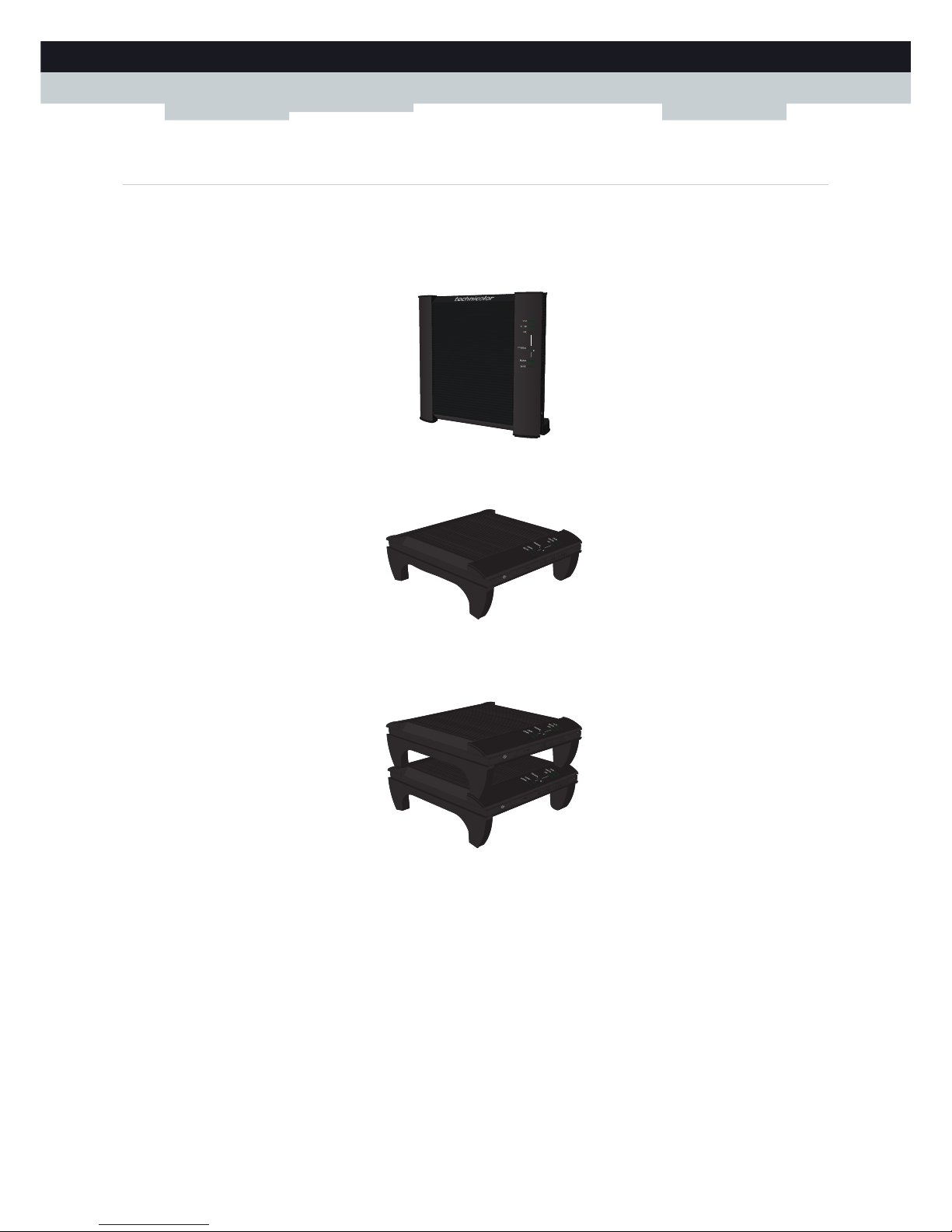
1.2 Housing
Mounting options
The MediaAccess Gateway can be used in the following has been designed can be mounted in the following positions:
Vertical:
Horizontal:
This position allows you to stack multiple MediaAccess Gateways.
On the wall:
To mount the MediaAccess Gateway on a wall, follow the instructions provided by the wall mount template that is
included in your box.
Page 13
7
1 GETTING STARTED
DMS-CTC-20111123-0002 v1.0
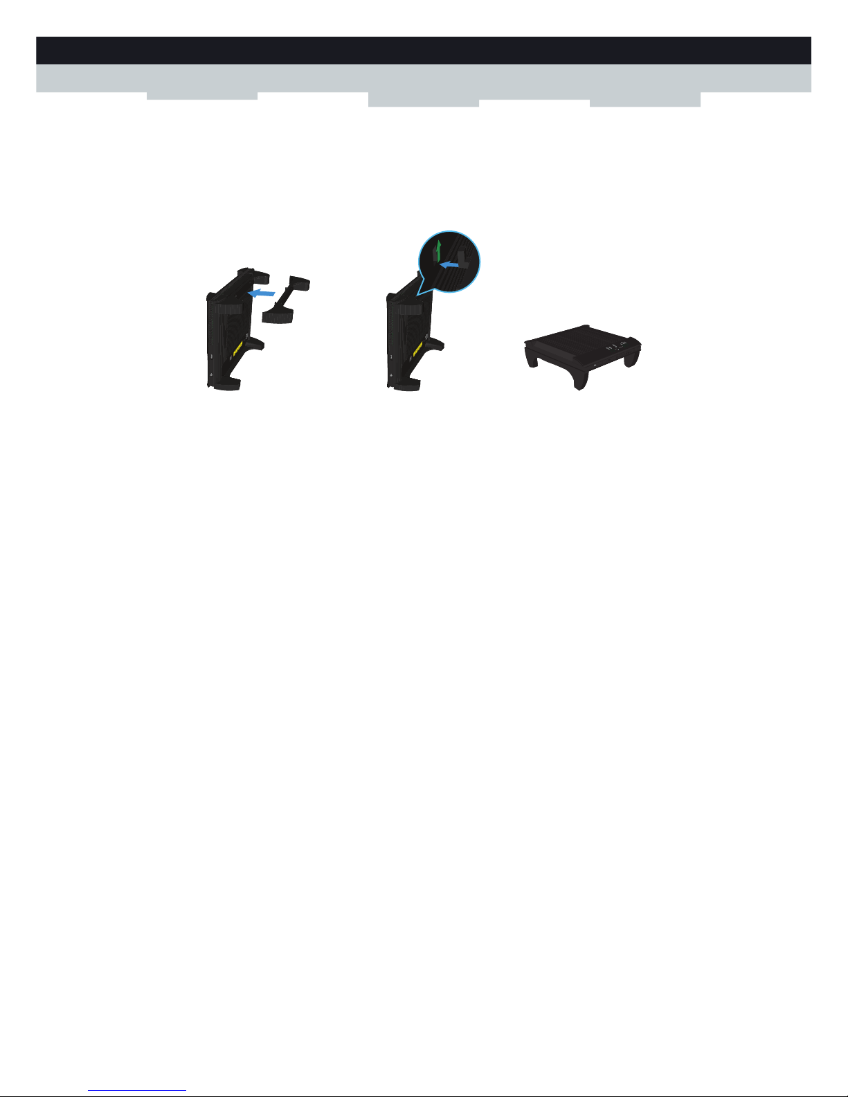
Placing your MediaAccess Gateway horizontally
To be able to place the MediaAccess Gateway in its horizontal position, you must first attach the mountable stand that is
included in your box.
Place the locking catches of the mounting stand into their slots on the MediaAccess Gateway and slide the mountable stand
into place.
1
2
Page 14

8
1GETTING START
ED
DMS-CTC-20111123-0002 v1.0
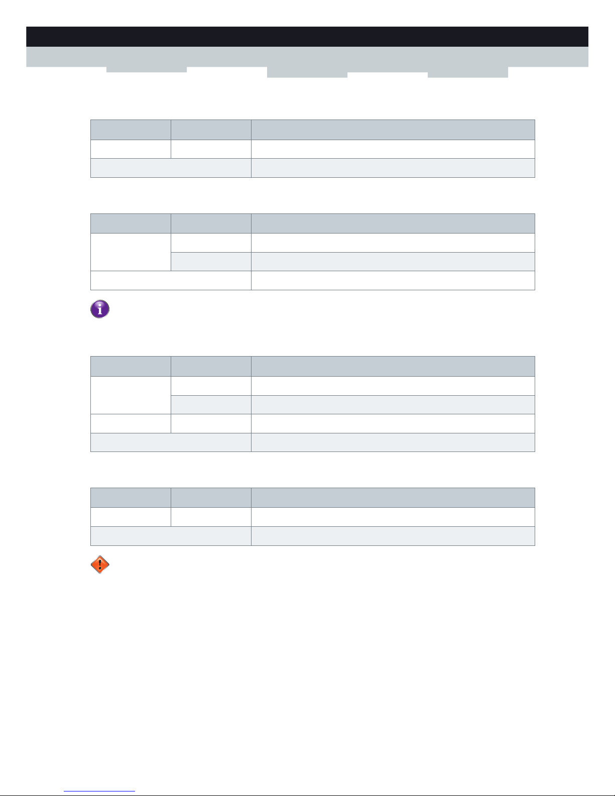
1.3 Components
Overview
This section provides an overview of the different components of the MediaAccess Gateway:
To p i c Page
1.3.1 Power 9
1.3.2 Local Network Connection 10
1.3.3 Broadband Connection 11
1.3.4 Console Connection 12
1.3.5 Buttons 13
1.3.6 Status LEDs 14
Page 15
9
1 GETTING STARTED
DMS-CTC-20111123-0002 v1.0
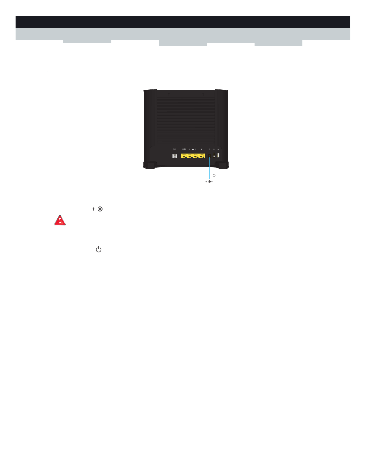
1.3.1 Power
Overview
Power inlet
The power inlet () allows you to connect the power supply.
Power switch
The power switch () allows you to power on/off your MediaAccess Gateway.
Only use the power supply delivered with your MediaAccess Gateway.
Page 16
10
1GETTING START
ED
DMS-CTC-20111123-0002 v1.0
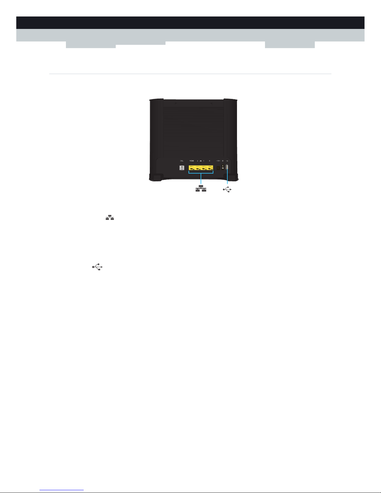
1.3.2 Local Network Connection
Overview
Ethernet switch
The Ethernet switch () allows you to connect an Ethernet device (for example, a computer) to your local network. For
more information, see “2.3 Connecting Your Network Devices to the MediaAccess Gateway” on page 20.
Ethernet port 1 is a Gigabit Ethernet port and has a maximum speed of 1 Gbps (Gigabit per second). The other Ethernet
ports have a maximum speed of 100Mbps (Megabit per second).
USB Port
The USB port () can be used to:
Connect a USB mass storage device to share your content (for example, music, movies,...):
On your local network via the Network File server or the UPnP AV Media Server.
On Internet via FTP.
For more information, see “5 Sharing Content” on page 53.
Connect your USB printer and share it with other users on your network. For more information, see “6 Sharing Your USB
Printer” on page 67.
Connect a 3G mobile adaptor to set up a 3G connection that can work as a backup for your main Internet connection.
For more information, see “2.5 Setting Up the 3G Fall-Back WAN Connection” on page 22.
Page 17
11
1 GETTING STARTED
DMS-CTC-20111123-0002 v1.0
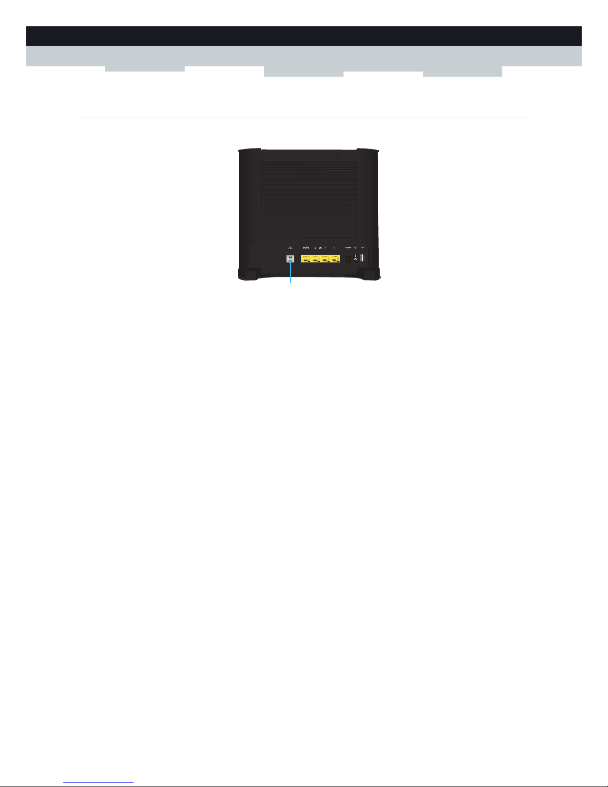
1.3.3 Broadband Connection
Overview
DSL port
This port can be used to connect your MediaAccess Gateway to your service provider’s SHDSL network.
Your MediaAccess Gateway supports the following SHDSL types:
single-pair (1-pair) SHDSL
2-pair SHDSL
For more information, see “2.1 Connecting the MediaAccess Gateway to your Service Provider’s Network” on page 18.
DSL
Page 18
12
1GETTING START
ED
DMS-CTC-20111123-0002 v1.0
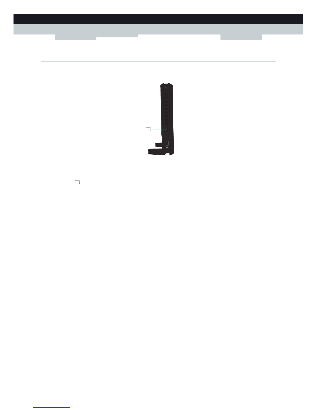
1.3.4 Console Connection
Overview
Console port
The Console ( ) port on the MediaAccess Gateway allows you to access your MediaAccess Gateway via a serial
connection. Via this serial connection, you can:
Access the Command Line Interface (CLI) to configure your MediaAccess Gateway.
View the traces of your MediaAccess Gateway.
For more information, see “3.3.2 Access the CLI via a Console Connection” on page 41.
Page 19

13
1 GETTING STARTED
DMS-CTC-20111123-0002 v1.0
1.3.5 Buttons
Overview
ECO button
The ECO ( ) button allows you to disable your wireless access point. You can do this when you do not have any devices
that are connected to the wireless access point. This allows you to save the energy that the MediaAccess Gateway would be
using for the wireless access point. For more information, see “ECO button” on page 52.
Reset button
The Reset button allows you to reset your MediaAccess Gateway to factory defaults.
For more information, see “9.5 Reset to Factory Defaults” on page 104.
Reset
Page 20
14
1GETTING START
ED
DMS-CTC-20111123-0002 v1.0
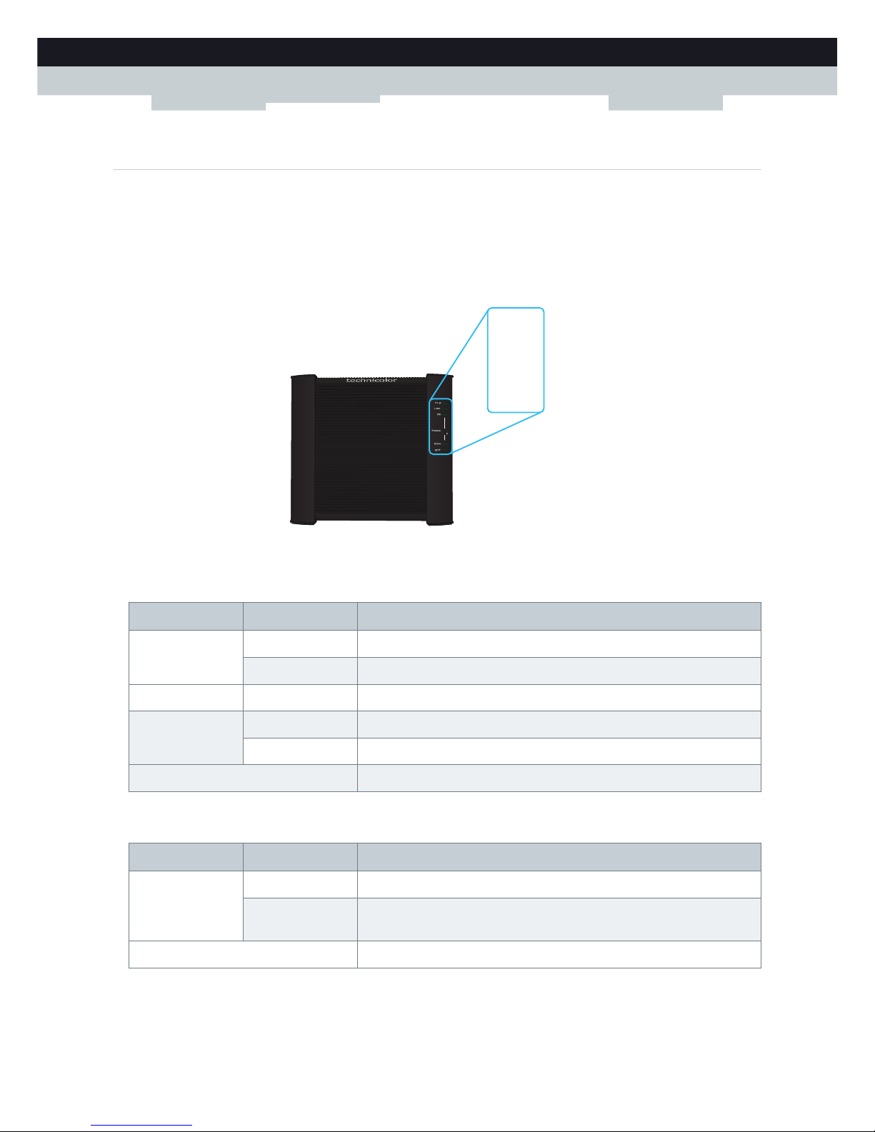
1.3.6 Status LEDs
Introduction
On the front panel of your MediaAccess Gateway, you can find a number of status LEDs, indicating the state of the device.
Power LED
Ethernet LED
Power
Ethernet
USB
Broadband
Internet
Upgrade
Colour State Description
Green Solid on Power on, normal operation
Blinking Bootloader active (during upgrade)
Red Solid on Power on, self-test failed, indicating device malfunction
Orange Solid on Bootloader selftest
Blinking Bootloader active (during upgrade)
Off The MediaAccess Gateway is powered off.
Colour State Description
Green Solid on Network device connected to the Ethernet switch.
Blinking Network device connected to the Ethernet switch and sending/receiving
data.
Off No Ethernet connection on your local network
Page 21
15
1 GETTING STARTED
DMS-CTC-20111123-0002 v1.0
USB LED
Broadband LED
Internet LED
Upgrade LED
Colour State Description
Green Solid on Device(s) connected to the MediaAccess Gateway’s USB port
Off No device connected to the MediaAccess Gateway’s USB port
Colour State Description
Green Solid on DSL line synchronised
Blinking Trying to detect carrier signal or pending DSL line synchronisation
Off MediaAccess Gateway powered off.
Each SHDSL pair has its own LED. The pair number is indicated next to the LED.
Colour State Description
Green Solid on Connected to the Internet, no activity
Blinking Connected to the Internet, sending/receiving data
Red Solid on Failed to setup the Internet connection
Off No Internet connection
Colour State Description
Blue Solid on Software upgrade ongoing
Off No software upgrade ongoing
Do not power off your MediaAccess Gateway or disconnect any cables as long as the Upgrade LED is on.
Interrupting the upgrade procedure may damage your MediaAccess Gateway.
Page 22

16
1GETTING START
ED
DMS-CTC-20111123-0002 v1.0
1.4 Preparing for the Installation
Local connection requirements
If you want to connect a computer using a wired connection, your computer must be equipped with an Ethernet Network
Interface Card (NIC).
Start with the installation
You are now ready to start with the installation of your MediaAccess Gateway.
Page 23

17
2 MANUAL INSTALLATION
DMS-CTC-20111123-0002 v1.0
2 Manual Installation
Installation
This chapter will help you to manually install your MediaAccess Gateway.
Setting up your network
Proceed as follows:
1 Connect your MediaAccess Gateway to your service provider’s network.
For more information, see “2.1 Connecting the MediaAccess Gateway to your Service Provider’s Network” on page 18.
2 Power on the MediaAccess Gateway.
For more information, see “2.2 Powering on the MediaAccess Gateway” on page 19.
3 Connect your computer to the MediaAccess Gateway.
For more information, see “2.3 Connecting Your Network Devices to the MediaAccess Gateway” on page 20.
4 Configure your MediaAccess Gateway.
For more information, see “2.4 Configure the MediaAccess Gateway” on page 21.
5 Share your content or media on your local network, continue with “5 Sharing Content” on page 53.
6 If you purchased the mobile USB adapter, setup the 3G backup connection.
For more information, see “2.5 Setting Up the 3G Fall-Back WAN Connection” on page 22.
7 Once you successfully installed your MediaAccess Gateway, it is recommend to backup your configuration. This will
allows you to return to this configuration when needed (for example, after misconfiguration). For more information, see
“3.2 Backing Up/Restoring your Configuration” on page 38.
Page 24
18
2MANUAL INSTAL
LATION
DMS-CTC-20111123-0002 v1.0
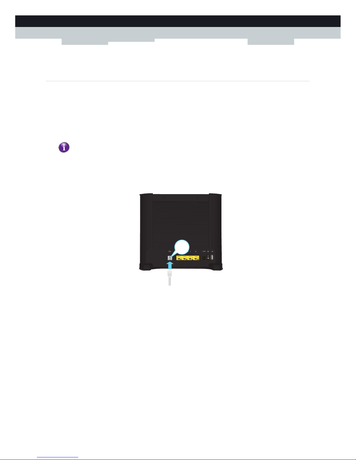
2.1 Connecting the MediaAccess Gateway to your Service
Provider’s Network
Introduction
This section helps you to connect the MediaAccess Gateway to your service provider’s network.
Connecting the cables
Proceed as follows:
1 Take the DSL cable. This is the grey cable that is included in your box.
2 Plug one end of the cable in the grey DSL port on the back of your MediaAccess Gateway.
3 Plug the other end of the cable into the SHDSL source.
If your service provider is providing:
single-pair (1-pair) SHDSL, then you need a cable with at least two wires (i.e. one pair).
2-pair SHDSL, then you need a cable with at least four (i.e. two pair).
Use the gray cable provided in your box.
DSL
Page 25

19
2 MANUAL INSTALLATION
DMS-CTC-20111123-0002 v1.0
2.2 Powering on the MediaAccess Gateway
Procedure
Proceed as follows:
1 Connect the power cord to the power port of the MediaAccess Gateway.
2 Plug the other end of the power cord into an electrical outlet.
3 Press the power button to turn on the MediaAccess Gateway.
4 Wait at least two minutes to allow the MediaAccess Gateway to complete the start up phase.
Page 26
20
2MANUAL INSTAL
LATION
DMS-CTC-20111123-0002 v1.0
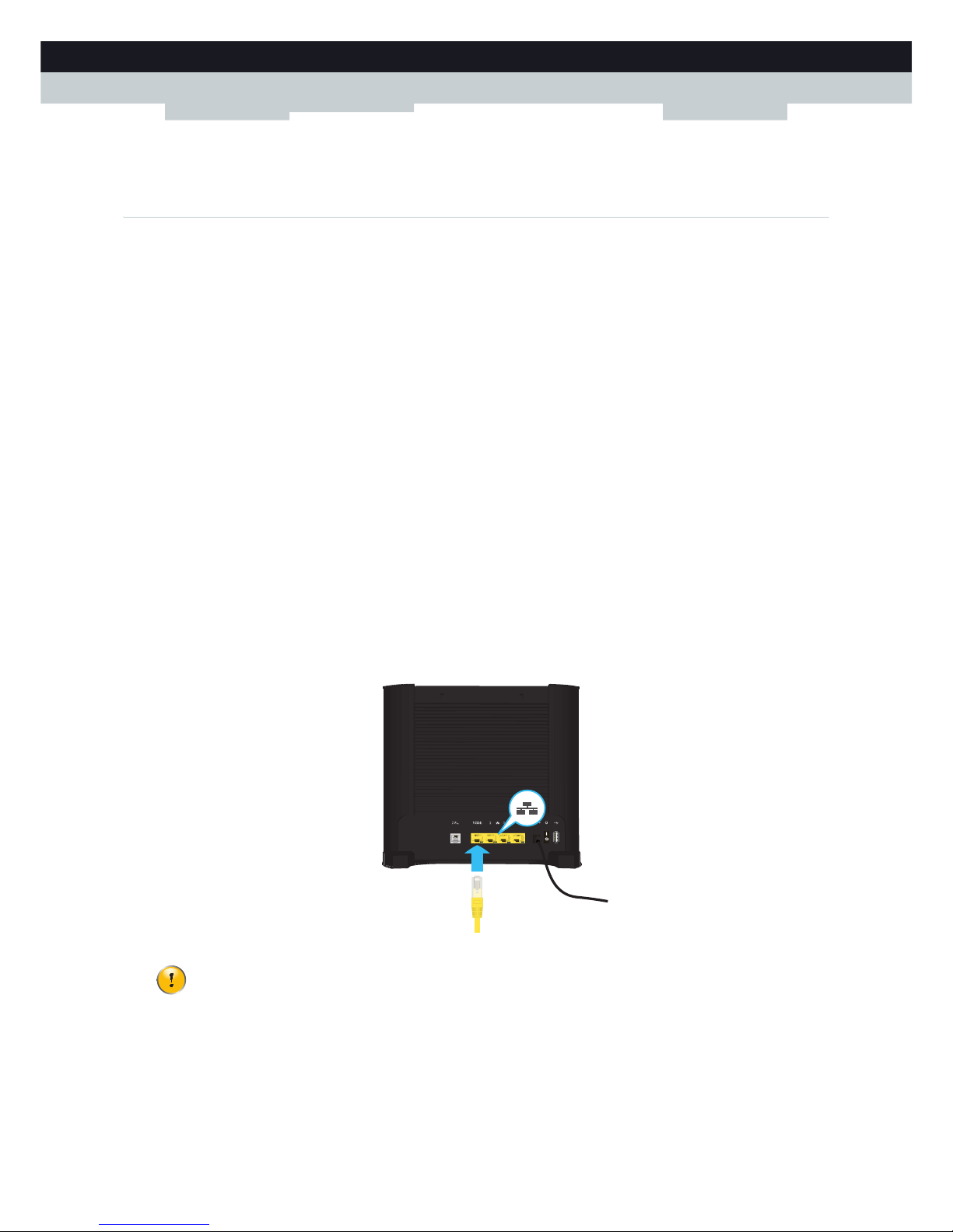
2.3 Connecting Your Network Devices to the MediaAccess
Gateway
Requirements
Both your network device (for example, a computer, a gaming console,...) and MediaAccess Gateway must have a free
Ethernet port.
Your network device must be configured to obtain an IP address automatically. This is the default setting.
Connection speed
Ethernet port 1 is a Gigabit Ethernet port and has a maximum speed of 1 Gbps (Gigabit per second). The other Ethernet
ports have a maximum speed of 100Mbps (Megabit per second).
Ethernet cable
In your package, you will find a cable with yellow connectors. This is the Ethernet cable.
When using other cables than the ones provided in your box, make sure to use the correct type of cable:
Category 5 (CAT5) cables are used for 10/100Mb Ethernet.
Category 5 Enhanced (CAT5E) cables help to prevent cross-talk and are used for 10/100Mb/1000Mb(Gigabit Ethernet)
Category 6 (CAT6) cables are similar to Cat 5E cables but have larger gauge wires and are used for 10/100/1000Mb
(Gigabit Ethernet). This cable is better than CAT5E for Gigabit Ethernet.
Procedure
Proceed as follows:
1 Connect one end of the Ethernet cable to one of the yellow Ethernet ports of your MediaAccess Gateway:
2 Connect the other end of the Ethernet cable to your network device.
3 Your network device is now connected to your network. No additional configuration is needed unless specified by your
service provider.
The MediaAccess Gateway does not support Power over Ethernet (PoE). All network devices that are connected
to the MediaAccess Gateway must be powered by their own power source.
Page 27
21
2 MANUAL INSTALLATION
DMS-CTC-20111123-0002 v1.0
2.4 Configure the MediaAccess Gateway
Introduction
If your service provider did not preconfigure your MediaAccess Gateway, you may have to configure the MediaAccess
Gateway via its Graphical User Interface (GUI).
Requirements
JavaScript must be enabled on your web browser (this is the default setting). For more information, consult the help of your
web browser.
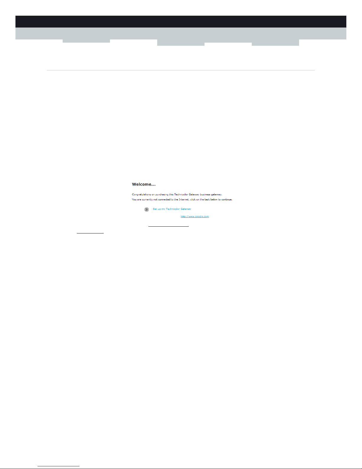
Procedure
Proceed as follows:
1 Open your web browser.
2 The MediaAccess Gateway informs you that you have not yet configured your MediaAccess Gateway.
If this window does not appear, browse to http://dsldevice.lan
or to the IP address of your MediaAccess Gateway (by
default: 192.168.1.254
) and click Technicolor Gateway on the menu on the left-hand side.
3 Click Setup my Technicolor Gateway.
4 The Easy Setup wizard appears. This wizard will guide you through the configuration of your MediaAccess Gateway.
Click Next and follow the instructions.
Page 28

22
2MANUAL INSTAL
LATION
DMS-CTC-20111123-0002 v1.0
2.5 Setting Up the 3G Fall-Back WAN Connection
Introduction
Many SOHO (Small Offices, Home Offices) and SME (Small/Medium Enterprises) businesses choose DSL as their access
technology for a Wide Area Network (WAN) connection because this is typically cheaper than using leased lines. A dropout
of a DSL line can however have expensive consequences due to inaccessibility of the Internet and E-mail. Therefore backup
solutions are available that provide an alternative path when the DSL line is down.
For example it is possible to switch to 2G / 3G mobile access technologies such as GPRS, UMTS, HSDPA, HSUPA,
HSPA+, WIMAX and LTE when internet connectivity is not available via the main WAN connection. By plugging a mobile
USB adapter into one of the USB ports of your MediaAccess Gateway, IP connectivity via a 2G / 3G network becomes
possible.
3G is an umbrella-term to indicate the third generation mobile telephony technology. The services associated with 3G
provide the ability to transfer both voice data and non-voice data. 3G networks are the successors of the 2G networks, such
as the GSM networks and provide new services and higher data transfer speeds.
What do I need?
To start using 2G / 3G as a connection on the MediaAccess Gateway, you need:
A mobile USB adapter
A registered Security Identity Module (SIM) card.
Configure 2G / 3G as WAN connection
Proceed as follows:
1 Create a mobile interface for your MediaAccess Gateway.
For more information, see “2.5.1 Setting up a Mobile Interface” on page 24.
2 Configure the newly created mobile interface as your backup connection.
For more information, see “2.5.2 Configuring a Backup Mobile Connection” on page 26.
3 Insert your mobile USB adapter.
For more information, see “2.5.4 Inserting a Mobile USB Adapter” on page 29.
4 Now your mobile connection is up and ready to use.
Result
MediaAccess Gateway will automatically enable your 3G backup connection when both of the following conditions are met:
The main Internet connection has been unavailable for at least 60 seconds.
The MediaAccess Gateway received a request to access the Internet (for example, when browsing to an Internet web
site).
Only use the mobile USB adapters provided by your service provider.
Remember to always assign a higher DNS and (default) route metric compared to the existing metrics used for
traffic going over the main WAN interface (DSL/ Ethernet / Fiber To The Home (FTTH)). This way the main
WAN connection is always preferred above the mobile connection when up.
If you need to remove your mobile USB adapter, make sure the MediaAccess Gateway is powered off first.
Page 29

23
2 MANUAL INSTALLATION
DMS-CTC-20111123-0002 v1.0
The MediaAccess Gateway will automatically disable the 3G connection in either of the following cases:
The main Internet connection is available again. In this case the MediaAccess Gateway switches back to the main Internet
connection.
No Internet traffic has been detected during the last 10 seconds. For example, you finished surfing the Internet.
Page 30
24
2MANUAL INSTAL
LATION
DMS-CTC-20111123-0002 v1.0
2.5.1 Setting up a Mobile Interface
Procedure
To set up the mobile interface complete the following steps:
Step 1: Start a CLI session.
Step 2: Add a mobile interface
Step 3: Configure a mobile interface
Step 4: Attach the mobile interface
Step 1: Start a CLI session
For more information, see “3.3 The Command Line Interface (CLI)” on page 39.
Step 2: Add a mobile interface
Execute the following command:
With the following parameters:
intf
The name of the mobile USB interface.
Example:
Step 3: Configure a mobile interface
Execute the following command:
With the following parameters:
intf
The name of the mobile USB interface.
pin
This parameter represents the PIN code of the SIM card.
puk
This parameter represents the PUK code of the SIM card.
apn
The Access Point Name (APN) used to access the packet switched services of the operator. The APN syntax must follow
the rules specified in the standard 3GPP23.003. It is recommended to always specify this value. If not specified, the
network will try to fill in the APN but may fail.
:mobile ifadd intf=<string>
:mobile ifadd intf=mobile_usb
With the command mobile ifdelete intf you can delete a mobile USB interface.
:mobile ifconfig intf=<string> [pin=<password>] [puk=<string>]
[apn=<string>] [mode=<{automatic|manual}>]
[operator=<number{0-99999}>] [technology=<{2G|3G}>]
[initcommand=<string>]
Only if you failed three times to attach the mobile interface using a wrong (unique) PIN code, the PUK code will
be used instead of the PIN code. It is advised to always fill in this parameter.
Page 31

25
2 MANUAL INSTALLATION
DMS-CTC-20111123-0002 v1.0
mode
The automatic (default) or manual selection of the mobile operator and technology.
operator
This parameter can be used to fill in the Location Area Identifier. This code consists of a three-digit Mobile Country
Code (MCC) and a two-digit Mobile Network Code (MNC). For a list of all available Location Area Identifiers, please
refer to http://www.itu.int/dms_pub/itu-t/opb/sp/T-SP-E.212B-2010-PDF-E.pdf
.
technology
The initial radio access technology (2G / 3G) to use for connection. If the selected technology is not available, the
alternative will be used.
initcommand
The AT command to be executed between SIM verification and the actual network connection. This command can be
used to perform vendor specific actions that are required for a successful connection.
Example:
To check all your mobile connection configurations, use the following command:
Step 4: Attach the mobile interface
Execute the following command:
With the following parameters:
intf
The name of the mobile USB interface.
Example:
It is advised to select manual mode and fill in the mobile operator and technology.
Your mobile interface can only be configured if it is not attached.
:mobile ifconfig intf=mobile_usb pin=1234 apn=web.provider.com operator=20610 technology=3G
mode=manual puk=12345678 initcommand=ATE
=>:mobile iflist
mobile_usb:
pin: ****
puk:
APN: web.provider.com
mode: automatic
operator: 0
technology: 3G
init command:
=>
To check the configuration of a specific mobile connection use the command mobile iflist intf=<your
intf>.
:mobile ifattach intf=<string>
:mobile ifattach intf=mobile_usb
With the command mobile ifdetach intf=<string> you can detach a mobile USB interface.
Page 32

26
2MANUAL INSTAL
LATION
DMS-CTC-20111123-0002 v1.0
2.5.2 Configuring a Backup Mobile Connection
Dial-On-Demand
By enabling the Dial-on-Demand (DoD) function when setting up the PPP interface, the new 2G / 3G connection will
function as a backup connection:
The “doddelay” (DoD delay) timer is the amount of time the MediaAccess Gateway waits before triggering the mobile
connection.
After injecting the mobile connection interfaces in the routing table, you will also notice a trigger interface (for default
routes) appearing (with according metric) in the routing table. When the main WAN interface goes down and the mobile
connection establishes, this trigger interface will disappear.
As long the main WAN connection is down, traffic will go over the mobile connection (routes with the higher metrics).
When the main WAN connection comes up again, DoD will injecting the DNS and routes with lower metric of the main
WAN connection in the routing table. According to the routing principles this will cause traffic to go over the main WAN
connection again.
The “Idletime” timer is the amount of time the MediaAccess Gateway waits before removing the DNS and routes of the
mobile connection once no more traffic is detected on this connection. During this time-out, two identical routes will exist
in the routing table, yet with different metrics. The lowest metric will be used according to routing principles.
Procedure
To configure the backup connection, complete the following steps:
Step 1: To set up a PPP interface
Step 2: Enable NAT address translation for the new PPP interface
Step 3: Save your changes!
Step 1: To set up a PPP interface
Proceed as follows:
1 To add a PPP interface, execute the following command:
2 Configure this PPP interface with a higher metric than the main WAN connection and enable the DoD function. The
user name and password are used for CHAP / PAP authentication for a specific APN:
3 Configure the route to add to the routing table when this interface comes up:
After starting up your MediaAccess Gateway, it might take some time until the main WAN connection comes up.
If this parameter is put to 0 an immediate parallel 2G / 3G connection will start up and disconnect immediately
when the main WAN connection has come up.
If this parameter is set to 0 and there is very few traffic over the 3G connection, each time new traffic is detected
on the 3G connection, the MediaAccess Gateway will attempt to switch back to its prioritized main WAN
connection.
:ppp ifadd intf=3G-Backup
:ppp ifconfig intf=3G-Backup dest=mobile_usb user=dummy password=dummy demanddial=enabled
idletime=60 doddelay=30 dnsmetric=20
:ppp rtadd intf=3G-Backup dst=0.0.0.0 metric=30
Your PPP interface can only be configured if it is detached.
Page 33

27
2 MANUAL INSTALLATION
DMS-CTC-20111123-0002 v1.0
4 Attach the newly configured PPP interface:
Step 2: Enable NAT address translation for the new PPP interface
Execute the following command:
Step 3: Save your changes!
Execute the following command:
:ppp ifattach intf=3G-Backup
:nat ifconfig intf=3G-Backup translation=enabled
:saveall
If you do not save your settings, all your changes will be lost after a powering of or restarting the MediaAccess
Gateway.
Page 34

28
2MANUAL INSTAL
LATION
DMS-CTC-20111123-0002 v1.0
2.5.3 Managing your Mobile Connection with the
MediaAccess Gateway GUI
Introduction
You can view and manage the parameters of your mobile connection via the MediaAccess Gateway GUI.
Procedure
To manage your mobile USB connection via the MediaAccess Gateway GUI:
1 Browse to the MediaAccess Gateway GUI.
For more information, see “3.1.1 Access” on page 33.
2 On the Broadband Connection menu, click Internet Services.
3 Click View more... for the mobile USB connection. The Overview page of the mobile USB connection is shown.
4 In the location bar, click Configure. The Configure page of the mobile connection appears.
5 Under Mobile Information, update the following fields if necessary:
APN:
The public APN used to access the Internet, or the private APN to access a local network.
Operator Mode:
2G / 3G / automatic (let the MediaAccess Gateway choose the best operator mode)
Pin:
The PIN code of your SIM card.
6 Click Apply to apply your configuration changes.
The mobile connection needs to be configured first before it is shown on the MediaAccess Gateway GUI.
Configuration changes via the MediaAccess Gateway GUI are automatically saved.
Page 35

29
2 MANUAL INSTALLATION
DMS-CTC-20111123-0002 v1.0
2.5.4 Inserting a Mobile USB Adapter
Procedure
Once the mobile connection is configured you can proceed as follows to insert the mobile USB adapter:
1 Power off the MediaAccess Gateway.
2 Insert your SIM card into the mobile USB adapter.
3 Plug the mobile USB adapter in (one of) the USB port(s) of your MediaAccess Gateway:
4 Power on the MediaAccess Gateway.
If you do not power off the MediaAccess Gateway first, the mobile USB adapter will not be detected.
Page 36

30
2MANUAL INSTAL
LATION
DMS-CTC-20111123-0002 v1.0
Page 37

31
3 CONFIGURATION TOOLS
DMS-CTC-20111123-0002 v1.0
3 Configuration Tools
Configuration Tools
You can use the following tools to configure your MediaAccess Gateway:
The MediaAccess Gateway Setup CD allows you to configure your MediaAccess Gateway and helps you to connect
your computers to the MediaAccess Gateway. For more information, see “2 Guided Installation” on page 15.
The MediaAccess Gateway GUI allows you to configure your MediaAccess Gateway via your web browser.
For more information, see “3.1 MediaAccess Gateway GUI” on page 32.
The Command Line Interface (CLI) allows you to configure every detail of your MediaAccess Gateway using textual
commands. For more information, see “3.3 The Command Line Interface (CLI)” on page 39.
Page 38

32
3CONFIGURATIO
N TOOLS
DMS-CTC-20111123-0002 v1.0
3.1 MediaAccess Gateway GUI
Introduction
The MediaAccess Gateway Graphical User Interface (GUI) allows you to configure your MediaAccess Gateway using your
web browser.
Requirements
JavaScript must be enabled on your browser (this is the default setting). For more information, consult the help of your web
browser.
Page 39

33
3 CONFIGURATION TOOLS
DMS-CTC-20111123-0002 v1.0
3.1.1 Access
Accessing the MediaAccess Gateway GUI
Proceed as follows:
1 Open your web browser.
2 Browse to http://dsldevice.lan
or to the IP address of your MediaAccess Gateway (by default: 192.168.1.254).
3 If you have protected your MediaAccess Gateway with a user name and password, the MediaAccess Gateway will
prompt you to enter these. Enter your user name and password and click OK.
4 The MediaAccess Gateway GUI appears.
Access the MediaAccess Gateway via UPnP
You can also access the MediaAccess Gateway GUI using the Internet Gateway Device (IGD) icon if your computer runs
one of the following operating systems:
Microsoft Windows 7
Microsoft Windows Vista
Microsoft Windows XP
For more information, see “7.1 UPnP” on page 78.
Remote access
It is also possible to access the MediaAccess Gateway GUI from the Internet. For more information, see “3.4 Access From
the Internet” on page 48.
For more information, see “3.1.3 Protecting Access to the MediaAccess Gateway” on page 37.
Page 40

34
3CONFIGURATIO
N TOOLS
DMS-CTC-20111123-0002 v1.0
3.1.2 Components
Overview
Depending on your user right and location on the GUI, the following components can be available:
Menu
The menu consists of the following menu items:
Home:
Allows you to go back to the MediaAccess Gateway home page.
Technicolor Gateway:
Provides basic information on the MediaAccess Gateway.
Broadband Connection:
Allows you to view/configure your broadband connections.
To o l b o x :
Allows you to configure the network services and security settings of your MediaAccess Gateway.
Office Network:
Allows you to manage your local network.
Label Description
1 Menu
2 Login section
3 Display level
4 Language bar
5 Notification area
6 Navigation bar
7 Content pane
8 Tasks pane
5
6
1
4
7
8
2
3
Page 41

35
3 CONFIGURATION TOOLS
DMS-CTC-20111123-0002 v1.0
Help:
Allows you to view context-related help information.
Each of these items contain a number of sub-menu items.
Login section
In the login section you can see the current user name.
By clicking the user name, you can:
Change your password.
Switch to another user.
Display level
The display level section allows you to switch the MediaAccess Gateway GUI to:
The Basic level:
The Basic level allows you to configure the basic MediaAccess Gateway settings and services. All changes that you make
are saved automatically.
The Expert level:
The Expert level allows you to configure the advanced settings. When you click Expert, the following menu items
appear:
Technicolor Gateway:
Allows you to view information on your MediaAccess Gateway, configure or upgrade it.
IP Router:
Allows you to view/configure the MediaAccess Gateway IP interfaces, IP routing table and NAT entries.
Connections:
Allows you to view/configure a broadband connection.
Local Networking:
Allows you to view/configure the MediaAccess Gateway DHCP server/client, the DNS configuration, the managed
Ethernet switch.
Firewall:
Allows you to view/configure the MediaAccess Gateway Firewall.
VPN (if supported):
Allows you to configure the MediaAccess Gateway for VPN.
Language bar
If more than one GUI language is available, a language bar is showed. This language bar allows you to change the language
of the MediaAccess Gateway GUI.
Notification area
The notification area displays:
Error messages, indicated by a red traffic light.
Warning messages, indicated by an orange traffic light.
Information messages, indicated by a green traffic light.
In Expert level, you must click Save All to make your changes permanent. If you do not do so, your changes will
be lost after rebooting the device.
If none of these events occur, the notification is not shown.
Page 42

36
3CONFIGURATIO
N TOOLS
DMS-CTC-20111123-0002 v1.0
Navigation bar
The Navigation bar displays your current position in the MediaAccess Gateway GUI.
Some page are available in different configuration levels. These pages have additional links (for example, Overview,
Configure) in the right part of the navigation bar that allow you to switch between the configuration levels.
Content pane
The content pane displays the information and configurable items of the selected item.
Tasks pane
To allow a quick configuration of your MediaAccess Gateway, some pages may offer you a number of related tasks in the
Pick a task list. These tasks will guide you to the page where you can perform the selected task.
Page 43

37
3 CONFIGURATION TOOLS
DMS-CTC-20111123-0002 v1.0
3.1.3 Protecting Access to the MediaAccess Gateway
Introduction
To prevent that every user on your local network can access the MediaAccess Gateway, the MediaAccess Gateway is
secured with a user name and password.
Default user name
The default user name is Administrator.
Default password
The default password is either blank or the ACCESS KEY printed on the label of your MediaAccess Gateway. This
depends on the settings chosen by your Service Provider.
Protected items
The following items are protected by these is will secure access to:
The MediaAccess Gateway GUI.
The embedded FTP Server.
for more information, see “5.3 The FTP Server” on page 62.
The Command Line Interface (CLI).
For more information, see The Command Line Interface (CLI).
How to change your password
Proceed as follows:
1 On the Toolbox menu, click User Management.
2 In the Pick a task list, click Change my password.
3 Enter your new password and click OK.
4 Your new password is now active. The next time that you log on to the MediaAccess Gateway GUI you will have to enter
this password.
It is recommended to change the default password settings.
Choose a password that your can easily remember or write it down. If you forget your password the only option is to
reset your MediaAccess Gateway. For more information, see “9.5 Reset to Factory Defaults” on page 104.
This password will also be used by the CLI, network file server and FTP server.
For more information about the CLI, see “5 Sharing Content” on page 53
For more information about the network file server and FTP server, see “5 Sharing Content” on page 53
Page 44

38
3CONFIGURATIO
N TOOLS
DMS-CTC-20111123-0002 v1.0
3.2 Backing Up/Restoring your Configuration
Introduction
Once you have configured your MediaAccess Gateway to your needs, it is recommended to backup your configuration for
later use. This way you can always return to your working configuration in case of problems.
Backing up your configuration
Proceed as follows:
1 Browse to the MediaAccess Gateway GUI.
For more information, see “Accessing the MediaAccess Gateway GUI” on page 33.
2 On the Technicolor Gateway menu, click Configuration.
3 In the Pick a task list, click Save or Restore Configuration.
4 Under Backup current configuration, click Backup Configuration Now.
5 The MediaAccess Gateway prompts you to save your backup file.
6 Save your file to a location of your choice.
Restoring your configuration
Proceed as follows:
1 Browse to the MediaAccess Gateway GUI.
For more information, see “Accessing the MediaAccess Gateway GUI” on page 33.
2 On the Technicolor Gateway menu, click Configuration.
3 In the Pick a task list, click Save or Restore Configuration.
4 Under Restore saved configuration, click Browse and open your backup file.
5 The MediaAccess Gateway restores your configuration.
Do not edit the backup files, this may result in corrupt files making them worthless as configuration backup.
Backup files usually have.ini as extension.
Page 45

39
3 CONFIGURATION TOOLS
DMS-CTC-20111123-0002 v1.0
3.3 The Command Line Interface (CLI)
Introduction
The CLI allows you to perform a command-based configuration of the MediaAccess Gateway:
Accessing the CLI
Users can access the Command Line Interface:
From the a local network or the Internet via:
A Telnet session
For more information, see “3.3.1 Access the CLI via Telnet” on page 40.
The MediaAccess Gateway GUI
For more information, see “3.3.3 Access the CLI from the GUI” on page 43.
Via serial connection to the Console interface.
For more information, see “3.3.2 Access the CLI via a Console Connection” on page 41.
The CLI is intended for advanced users only!
Page 46

40
3CONFIGURATIO
N TOOLS
DMS-CTC-20111123-0002 v1.0
3.3.1 Access the CLI via Telnet
Requirements
Your computer must be connected to the MediaAccess Gateway.
For more information, see “2.3 Connecting Your Network Devices to the MediaAccess Gateway” on page 20.
For Microsoft Windows 7 and Vista: the Telnet service must be enabled on your computer.
For more information, consult Windows’ help.
Access via a local Telnet Session
Proceed as follows:
1 Open the Command Prompt or Te r m i n a l .
2 Type telnet followed by the IP address of the MediaAccess Gateway (the default IP is 192.168.1.254) or the DNS name
assigned to your MediaAccess Gateway (by default dsldevice.lan):
3 The CLI now prompts you to log in. For more information, see “Login” on page 45.
Remote access
It is also possible start a CLI session from the Internet. For more information, see “3.4 Access From the Internet” on page 48.
telnet 192.168.1.254
Page 47

41
3 CONFIGURATION TOOLS
DMS-CTC-20111123-0002 v1.0
3.3.2 Access the CLI via a Console Connection
Introduction
The console port on the MediaAccess Gateway allows you to access your MediaAccess Gateway via a serial connection.
This has the advantage that you do not need IP connectivity to be able to connect.
When the MediaAccess Gateway starts up, it will send traces to the serial console allowing you to follow the boot process of
the MediaAccess Gateway.
Requirements
To be able to connect to the serial interface your will need the following:
One normal straight through RJ45 Ethernet cable
One RJ45-to-DB9 convertor
If this item is not included in your box, contact your service provider to purchase one.
Terminal software to connect your computer to the MediaAccess Gateway over a serial connection (for example,
Microsoft HyperTerminal).
Procedure
Proceed as follows:
Step 1: Connect the cables.
Step 2: Setup the terminal connection.
Step 1: Connect the cables
Proceed as follows:
1 Plug the RJ45-to-DB9 connector into your computer’s serial port.
2 Plug one end of the Ethernet cable in the RJ45-to-DB9 connector.
3 Plug the other end into the MediaAccess Gateway’s console port.
Only use the convertor provided by your service provider. Other convertors may use other pin layouts and might
not be able to pass the signal correctly. For more information about the pin layout of this convertor, see “9.6 RJ45-
to-DB9 Pinout” on page 105.
Page 48

42
3CONFIGURATIO
N TOOLS
DMS-CTC-20111123-0002 v1.0
Step 2: Setup the terminal connection
Proceed as follows:
1 Open your terminal.
2 Establish a connection with the following parameters:
Baudrate: 115200 bits per second (bps)
Data bits: 8
Parity: None
Stop bits: 1
Flow control: None
3 Make sure that your session does not interpret received data. This may cause problems when upgrading your
MediaAccess Gateway via the CLI. To avoid this use the following settings:
Emulation: ANSIW
Telnet terminal ID: VT100
3 You are now connected to the MediaAccess Gateway’s serial interface. The MediaAccess Gateway now waits for you to
enter your user name and password. For more information, see “3.3.4 Using the CLI” on page 45.
Tr a c e s
You can also use the CLI for tracing. The following types of traces are available:
Startup traces
When the MediaAccess Gateway starts up, it will send traces to the serial console allowing you to follow the boot process
of the MediaAccess Gateway. To view the startup traces, restart or power on your MediaAccess Gateway after setting up
the terminal connection.
Real-time traces
Press:
CTRL+Q, to start displaying the real-time traces.
CTRL+S, to stop displaying the real-time traces.
These are the defaults settings. You can change these settings via the CLI.
To access these setting on Microsoft HyperTerminal:
1 On the File menu, click Properties.
2 Click the Settings tab.
Page 49

43
3 CONFIGURATION TOOLS
DMS-CTC-20111123-0002 v1.0
3.3.3 Access the CLI from the GUI
Procedure
Proceed as follows:
1 Browse to the MediaAccess Gateway GUI.
For more information, see “Accessing the MediaAccess Gateway GUI” on page 33.
2 In the Display Level list, click Expert.
3 In the upper-right corner, click CLI.
4 The MediaAccess Gateway CLI pages page appears:
The CLI command tree
On the left of the page, you can find the command tree. This tree contains all CLI commands that are available for
configuration.
Command types
The commands are three types of commands that can be identified by the icon displayed next to the command:
Icon Description
Command group
Function that does not require input. The results are immediately displayed.
Function that requires input. When you click on this function, a page will appear where you can enter the
parameters.
Parameters that are required will be explicitly labelled as required.
Page 50

44
3CONFIGURATIO
N TOOLS
DMS-CTC-20111123-0002 v1.0
Executing a command
Proceed as follows:
1 In the command tree, select the command that you want to execute.
2 The command page appears:
Enter in the command parameters and click Apply.
Save your changes!
The changes that you make are only temporary and will be lost after restarting the MediaAccess Gateway. You
must click Save All to save your changes permanently.
Page 51

45
3 CONFIGURATION TOOLS
DMS-CTC-20111123-0002 v1.0
3.3.4 Using the CLI
Login
When starting a CLI session you will have to go through the following steps:
1 When prompted, enter your user name and password.
2 After entering your user name and password, the MediaAccess Gateway banner pops up, followed by the CLI prompt.
3 You can now start entering your commands.
Menu mode
Next to the command-based input, the CLI also features an intuitive menu-based interface. This is mode gives you a quick
overview of the available commands and is ideal for users who are just starting to use the CLI.
To use start this interface execute the menu command.
Username : Administrator
Password :******
For more information, see “3.1.3 Protecting Access to the MediaAccess Gateway” on page 37.
------------------------------------------------------------------------
______ MediaAccess TG650s
___/_____/\
/ /\\
_____/__ / \\
_/ /\_____/___ \
// / \ /\ \
_______//_______/ \ / _\/______
/ / \ \ / / / /\
__/ / \ \ / / / / _\__
/ / / \_______\/ / / / / /\
/_/______/___________________/ /________/ /___/ \
\ \ \ ___________ \ \ \ \ \ /
\_\ \ / /\ \ \ \ \___\/
\ \/ / \ \ \ \ /
\_____/ / \ \ \________\/
/__________/ \ \ /
\ _____ \ /_____\/
\ / /\ \ /___\/
/____/ \ \ /
\ \ /___\/
\____\/
-----------------------------------------------------------------------=>
=>menu
┌──────┐
┌─────────────────────────────────┤ menu ├──────────────────────────────────┐
│ └──────┘ │
│[contentsharin [firewall] [printersharin [pwr] [service] │
│[dsd] [ptrace] [statecheck] [tftp] [aaa] │
│[config] [connection] [cwmp] [debug] [dhcp] │
│[dns] [dyndns] [env] [eth] [atm] │
│[expr] [hostmgr] [ids] [igmp] [interface] │
│[ip] [ipqos] [label] [language] [mbus] │
│[memm] [mlp] [mobile] [nat] [ppp] │
│[pptp] [router] [script] [snmp] [sntp] │
│[software] [syslog] [system] [tls] [tunnel] │
│[upgrade] [upnp] [user] [vfs] [voice] │
│[wansensing] [webserver] [wireless] [xdsl] │
│ │
│ │
├───────────────────────────────────────────────────────────────────────────┤
│ <Ok> <Cancel> │
└───────────────────────────────────────────────────────────────────────────┘
Page 52
46
3CONFIGURATIO
N TOOLS
DMS-CTC-20111123-0002 v1.0
Use:
The arrow keys to select a command(group)
The TAB key to switch between the OK and Cancel button.
CTRL+C to switch back to exit the menu mode.
The Help Command
Execute help or ? from top level to list all available commands and command groups for the MediaAccess Gateway
You can execute the help command from each command group selection. This results in a list of the available commands
(and underlying command groups, if available) in this particular command group.
Example:
Command Completion
When you type the first letters of your command, you can complete the command by pressing TAB.
To be able to complete the command automatically, the part to be added must be unique. If the part is not unique, the CLI
will provide a list of possible commands.
Completion works for:
Command groups
Commands
Options
Values coming from a list
Command Line Navigation
Press:
CTRL+A to go to the beginning of the command line.
CTRL+L to go to the end of the command line.
Breaking off Commands
You can break off a command by pressing CTRL+G or CTRL+C. This can be useful in a situation where a user is prompted
to enter a value which he does not know and wants to quit the command. Instead of being prompted over and over again for
the same value, this allows to quit the command and return to the command line prompt.
Example:
In the example below, CTRL+C is pressed after the third prompt:
[firewall]=>help
Following commands are available :
config : Display/Modify firewall configuration.
clear : Clear firewall configuration.
list : Display firewall configuration.
Following command groups are available :
chain debug level rule
Executing, for example, :help firewall from any level gives the same result as executing help from the
firewall command group.
[firewall chain]=>add
chain =
Required parameter (use ctrl-c or ctrl-g to abort)
chain =
Required parameter (use ctrl-c or ctrl-g to abort)
chain =
[firewall chain]=>
Page 53

47
3 CONFIGURATION TOOLS
DMS-CTC-20111123-0002 v1.0
History of Commands
Use the UP and DOWN arrow keys to select a previously executed command. Press ENTER to execute the selected
command.
More information
For a complete list of available CLI commands, you can download the MediaAccess TG650s CLI reference Guide from
www.technicolor.com
.
Page 54

48
3CONFIGURATIO
N TOOLS
DMS-CTC-20111123-0002 v1.0
3.4 Access From the Internet
Modes
To access your MediaAccess Gateway from the Internet, you can choose between two modes:
Permanent Mode (Remote Access):
The remote session ends when you disable remote assistance or after restarting your MediaAccess Gateway.
Temporary Mode (Remote Assistance):
The remote session ends when you disable remote assistance, after restarting your MediaAccess Gateway or after 20
minutes of inactivity.
To enable Remote Assistance / Remote Access.
To enable remote assistance/access:
1 Browse to the MediaAccess Gateway GUI.
For more information, see “Accessing the MediaAccess Gateway GUI” on page 33.
2 Complete and check the following parameters:
Mode:
Select the mode that you want to use.
URL:
Contains the URL that must be used to access the MediaAccess Gateway from the Internet.
User name and Password:
Contains the user name and password are needed to access your MediaAccess Gateway remotely. If wanted you can
change the automatically generated password in the Password box.
3Click Enable Remote Assistance.
Accessing your MediaAccess Gateway from the Internet
Proceed as follows:
1 Open your web browser.
2 Type the URL that was listed in the URL field on the Remote Assistance page (for example https://141.11.249.150:51003).
3 Enter the user name and password that you specified on the Remote Assistance page.
4 The MediaAccess Gateway GUI appears.
It is now possible for a remote user to access your MediaAccess Gateway via the specified URL using the provided user
name and password.
Enabling remote assistance is only possible when you are connected to the Internet.
You can replace the IP address in this URL by the dynamic DNS host name if you enabled and configured
Dynamic DNS. For more information, see Dynamic DNS.
Example: https://141.11.249.150:51003 can be replaced by https://mygateway.dyndns.org:51003.
Page 55

49
4 SAVING ENERGY
DMS-CTC-20111123-0002 v1.0
4 Saving Energy
Code of Conduct
To prove its commitment to protect the environment, Technicolor has signed the Code of Conduct, a global agreement to
reduce the power consumption of broadband access devices.
For more information, see “4.1 Code of Conduct” on page 50.
Technicolor power saving innovations
To further reduce the power consumption, Technicolor has developed the ECO Manager. This system constantly monitors
the services provided by the MediaAccess Gateway and automatically switches unused services to an ECO-friendly state.
For more information, see “4.2 ECO Manager” on page 51.
Next to this automated tool, you can also choose to manually disable services that you will not be using. For more
information, “4.3 Manually Switching Off Services to Reduce Power” on page 52.
Page 56

50
4 SAVING ENERGY
DMS-CTC-20111123-0002 v1.0
4.1 Code of Conduct
Power states
Code of Conduct provides rules for the power consumption in:
Full power state:
This is the normal operation mode of the device, where all functionality is enabled.
Low power state:
When there is no user traffic on the device, the device should switch to low power mode. This is a state in which devices
are only allowed to use a limited amount of energy to be able to power its components and respond to user activity.
Example
Take the following example:
The user switches off his computer at 20:00.
There are no other devices connected to the MediaAccess Gateway.
The MediaAccess Gateway switches to low power mode. This results in a considerable drop in the overall power
consumption of the MediaAccess Gateway.
No user traffic
User traffic
Time
Power
Consumption
Full power limit
Low power limit
20:00
Page 57

51
4 SAVING ENERGY
DMS-CTC-20111123-0002 v1.0
4.2 ECO Manager
Introduction
The MediaAccess Gateway constantly monitors the user activity and uses this information to optimise the power
consumption:
For example:
The MediaAccess Gateway reduces the clock frequency of the central processor when there is no or low user activity.
This lowered clock frequency will result in a lower power consumption of the MediaAccess Gateway.
Disable the USB port(s) when they are not used
Switch the wireless interface to power reduction mode.
Wireless access point power reduction mode
When the MediaAccess Gateway access point switches to power reduction mode, the access point is switched off and is
only power on periodically to be able to detect new clients. If new clients are detected the wireless access point is fully
powered again. This is only possible if there are no devices connected to the MediaAccess Gateway.
Power reduction is enabled by default, but it is possible to disable it via the MediaAccess Gateway GUI. To configure power
reduction:
1 Browse to the MediaAccess Gateway GUI.
For more information, see “Accessing the MediaAccess Gateway GUI” on page 33.
2 Under Office Network, click Wireless.
3 In the Navigation bar, click Configure.
4 Under Configuration:
Select Power Reduction Enabled to enable power reduction.
Clear Power Reduction Enabled to disable power reduction.
5 Click Apply.
Example
If we use the same example as in the previous section, you can see that the MediaAccess Gateway is now able to further
reduce the power consumption in periods where less action is required from the MediaAccess Gateway.
No User Traffic
User Traffic
Time
20:00
Time
Power
Consumption
Full power limit
Low power limit
Page 58

52
4 SAVING ENERGY
DMS-CTC-20111123-0002 v1.0
4.3 Manually Switching Off Services to Reduce Power
ECO button
If you are not using the wireless access point of your MediaAccess Gateway, you might consider to disable the wireless
access point permanently. This allows you to further reduce the power consumption.
To turn the wireless interface:
Off, press the ECO ( ) button until the Wireless LED is off.
On, press the ECO ( ) button until the Wireless LED is on.
Zero power consumption
If you will not be using your MediaAccess Gateway for a longer time (for example: you are going on holiday), you should
consider to turn off the MediaAccess Gateway. This way no energy will be consumed at all.
However, be aware that if you turn off the MediaAccess Gateway, all services provided by the MediaAccess Gateway that
require access to the Internet will not be available. For example:
You will not be able to browse to Internet websites, listen to radio streams etc.
LAN-to-LAN and other IPSec services are not be available
No Digital TV is provided
If your set-top box is connected to your MediaAccess Gateway, it will no longer be able to connect to the Internet, hence
not be able to service your TV set.
Page 59

53
5 SHARING CONTENT
DMS-CTC-20111123-0002 v1.0
5 Sharing Content
Introduction
The MediaAccess Gateway allows you to share the content stored on your USB storage device with other users on your
network or even access this shared content from the Internet.
Features
The MediaAccess Gateway supports USB 2.0
The following file systems are supported:
NTFS (optional)
FAT32
FAT16
HFS+ (optional)
EXT2/EXT3 (optional)
You can connect up to five USB storage devices (via a USB hub).
Each USB storage device can have up to 10 partitions. If your device has more partitions the extra partitions will be
ignored.
Content Sharing Servers
The MediaAccess Gateway offers three types of services to share your content. The following table gives a you a brief
overview of the main functions:
Network File Server UPnP AV Media Server FTP Server
Function
Store and access your data
on your local network.
Make media files available
for UPnP AV capable
devices like Media players,
Set-Top boxes from your
local network.
Store and access your data
from the Internet.
Access
Read and write Read-only Read and write
Accessible from
Local network Local network Internet and Local network
Type of content shared
All files from all partitions
and disks that are
connected.
Media files (music, movies
and pictures) from all
partitions and disks that are
connected.
All files that are stored in
the Shared folder of the
managed partition.
For more information,
see...
“5.1 The Network File
Server” on page 55
“5.2 The UPnP AV Media
Server” on page 58
“5.3 The FTP Server” on
page 62
Page 60

54
5 SHARING CONTE
NT
DMS-CTC-20111123-0002 v1.0
Configuration
All servers are enabled by default. The only thing that you need to do is to plug your USB memory stick or external hard
disk in (one of) the USB port(s) of your MediaAccess Gateway.
By using a USB hub, you can connect up to five USB mass storage devices to the MediaAccess Gateway.
Do not remove your USB storage device without stopping it first, otherwise data might be lost! For more
information, see “5.5 Safely Removing your USB Storage Device” on page 66.
Page 61

55
5 SHARING CONTENT
DMS-CTC-20111123-0002 v1.0
5.1 The Network File Server
Introduction
The Network Server allows you to share the content on your USB storage device(s) with other devices that are connected to
your local network (mostly computers).
These devices have read and write access to this USB device(s).
Configuration
The Network File Server is enabled by default and ready for use.
To change the default settings, proceed as follows:
1 Browse to the MediaAccess Gateway GUI.
For more information, see “Accessing the MediaAccess Gateway GUI” on page 33.
2 On the Tools menu, click Content Sharing.
3 In the Navigation bar, click Configure.
4 Under Network File Server (Windows Networking), you can change the following settings:
Server Name:
Enter the name that you want to use to access the MediaAccess Gateway.
Server Description:
Add a short description for what kind of data is stored on the USB storage device.
Wo rkg ro up :
Enter the same workgroup as used by your computer(s).
Server Enabled:
Select this option to enable the Network File Server
5 Click Apply.
6 All users connected to the MediaAccess Gateway can now access the data on stored your USB storage device.
7 If you want to limit the number of folders that can be accessed, continue with “5.4 Managing your Shared Content” on
page 64.
Accessing the shared content on Windows
Proceed as follows:
1 Open Windows Explorer.
2 In the address bar, type two backslashes followed by the name that you entered in the Server Name box (default:
\\Technicolor).
If you did not provide a server name, type \\192.168.1.253.
If you made changes to the DHCP settings, the IP address may diff. For more information, see “Getting the IP
address of your USB storage device” on page 103.
Page 62

56
5 SHARING CONTE
NT
DMS-CTC-20111123-0002 v1.0
3 An Explorer windows appears. The storage devices that are attached to your MediaAccess Gateway are listed as folders.
If the storage device has multiple partitions an index number will be added at the end (for example: Disk_a1 and
Disk_a2).
If multiple storage devices are inserted the first one is listed as Disk_a1, the second one as Disk_b1, and so on.
If the partition is a managed partition, only the Media and Shared folders of the managed partition are displayed:
For more information on managed partitions, see “5.4 Managing your Shared Content” on page 64.
4 If you plan to frequently use this folder, it might be useful to map this folder as a network drive. For more information, see
the help of your operating system.
Accessing the shared content on Mac
Proceed as follows:
1 On the Go menu, click Connect To Server.
2 The Connect To Server window appears.
In the Server Address box, type smb://<server name>, where <server name> is the Server Name you assigned to your
USB storage device (default: smb://Technicolor).
If you did not provide a server name, type smb://192.168.1.253.
If you made changes to the DHCP settings, the IP address may diff. For more information, see “Getting the IP
address of your USB storage device” on page 103.
Page 63
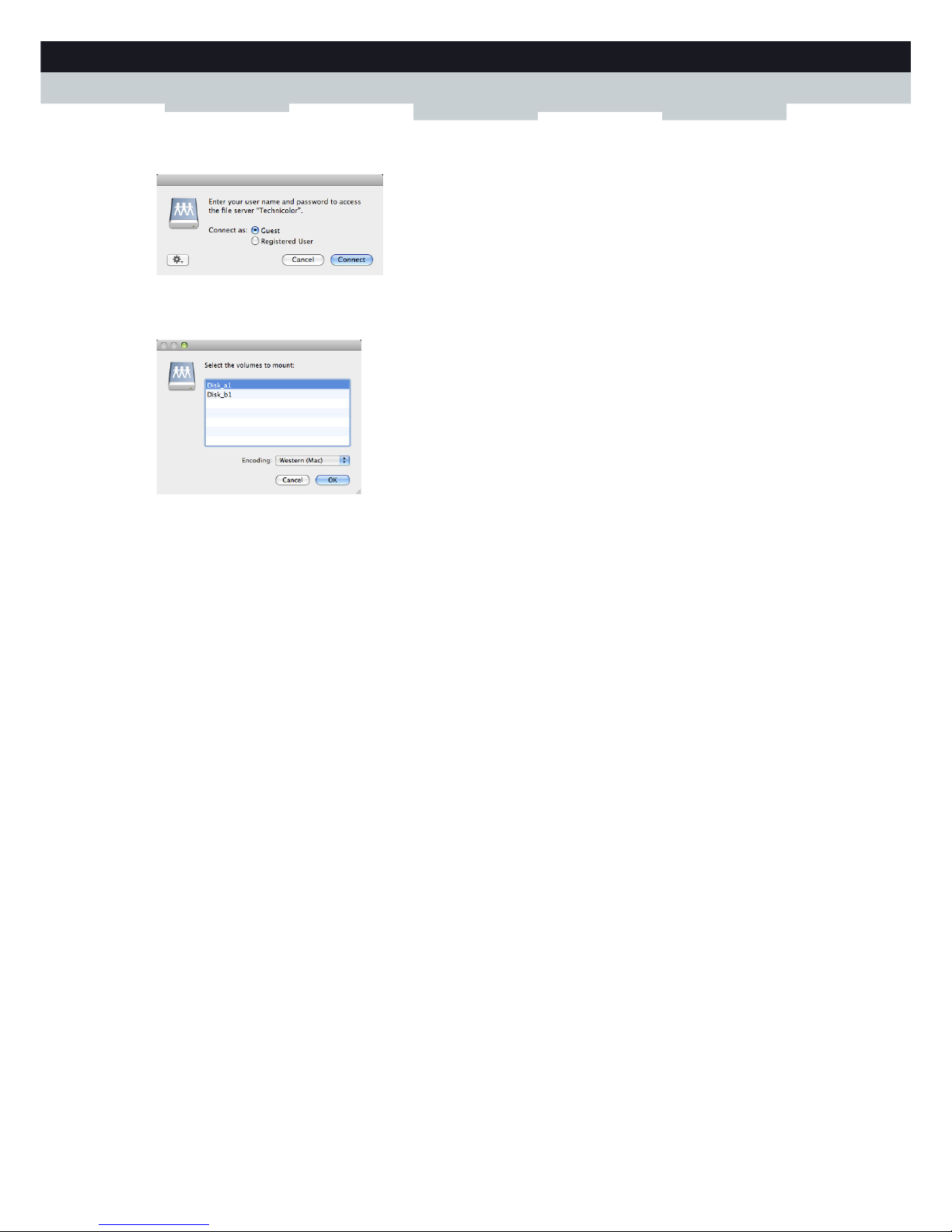
57
5 SHARING CONTENT
DMS-CTC-20111123-0002 v1.0
3 The following window appears:
Select Guest and click Connect.
4 If prompted, select the partition that you want to open and click OK:
5 Your USB storage device is now mounted and is displayed on your desktop.
Page 64

58
5 SHARING CONTE
NT
DMS-CTC-20111123-0002 v1.0
5.2 The UPnP AV Media Server
Introduction
Your MediaAccess Gateway has a built-in DLNA-certified UPnP AV media server. This section describes how to use and
configure this media server.
UPnP AV
UPnP AV (AV stands for Audio and Video) is a protocol especially designed to share media files on your local network.
DLNA-certified
The Digital Living Network Alliance (DLNA) is an organisation that imposes requirements to ensure the interoperatability
of your media devices and standardize the communication between them.
Buying a DLNA-certified device like the MediaAccess Gateway guarantees you that it will seamlessly integrate with your
other DLNA-certified devices.
To allow you to access your media in a quick and easy way, the MediaAccess Gateway scans your storage device for meta
data information (for example, title, artist, album) and stores it in a database. When you are looking for a file, the
MediaAccess Gateway can simply query the database instead of having to go through all the files.
UPnP AV network components
A UPnP AV network consists of the following components:
The UPnP AV server is directly connected to your media files and makes them available on the network. In your network
the MediaAccess Gateway will fulfil this role.
The UPnP AV client is a software application or hardware device that allows you to play or view the media files provided
by your UPnP AV media server.
This database will only be created if the following conditions are met:
Your disk or partition must have at least 250MB of free space
Your disk or partition must not be read-only.
Page 65

59
5 SHARING CONTENT
DMS-CTC-20111123-0002 v1.0
5.2.1 Configuring the UPnP AV Media Server
Introduction
The Network File Server is enabled by default and ready to use.
Enabling/disabling the UPnP AV Media Server
Proceed as follows:
1 Browse to the MediaAccess Gateway GUI.
For more information, see “Accessing the MediaAccess Gateway GUI” on page 33.
2 On the Tools menu, click Content Sharing.
3 In the Navigation bar, click Configure.
4 Under UPnP AV Media Server, click Server Enabled.
5 Click Apply.
Media Database
When you plug in your USB storage device, the MediaAccess Gateway will automatically start building the media database.
This database contains all meta data of the media files stored on your USB storage device.
To view the status of the media database:
1 Browse to the MediaAccess Gateway GUI.
For more information, see “Accessing the MediaAccess Gateway GUI” on page 33.
2 On the Tools menu, click Content Sharing.
3 In the Navigation bar, click Configure.
4 Under UPnP AV Media Server, you can find the Database Status.
5 If you want to rebuild the database, click Rebuild.
Page 66

60
5 SHARING CONTE
NT
DMS-CTC-20111123-0002 v1.0
5.2.2 Using the UPnP AV Media Server
Introduction
The UPnP AV Media Server lists all audio, video and picture files located on the connected USB storage device. All UPnP
AV renderers (for example, a DLNA-certified Set-Top box) that are connected to your network are able to view this list and
play or view items from this list.
On your UPnP AV renderer, the MediaAccess Gateway’s UPnP AV media server will be listed as Technicolor TGXXX.
Below you can find a screenshot taken on a smartphone with a UPnP AV client.
Via this entry, you can browse to your media files.
Windows 7
Windows 7 has native support for UPnP AV. It automatically detects UPnP AV and makes your media files available for
playback on your Windows Media Player.
Proceed as follows:
1 On the Windows Start menu, click Network.
2 The Network window appears:
Under Media Devices you will find the MediaAccess Gateway’s UPnP AV Media Server (displayed as Technicolor
TGXXX).
3 Double-click the MediaAccess Gateway’s UPnP AV Media Server to access your media files.
Page 67
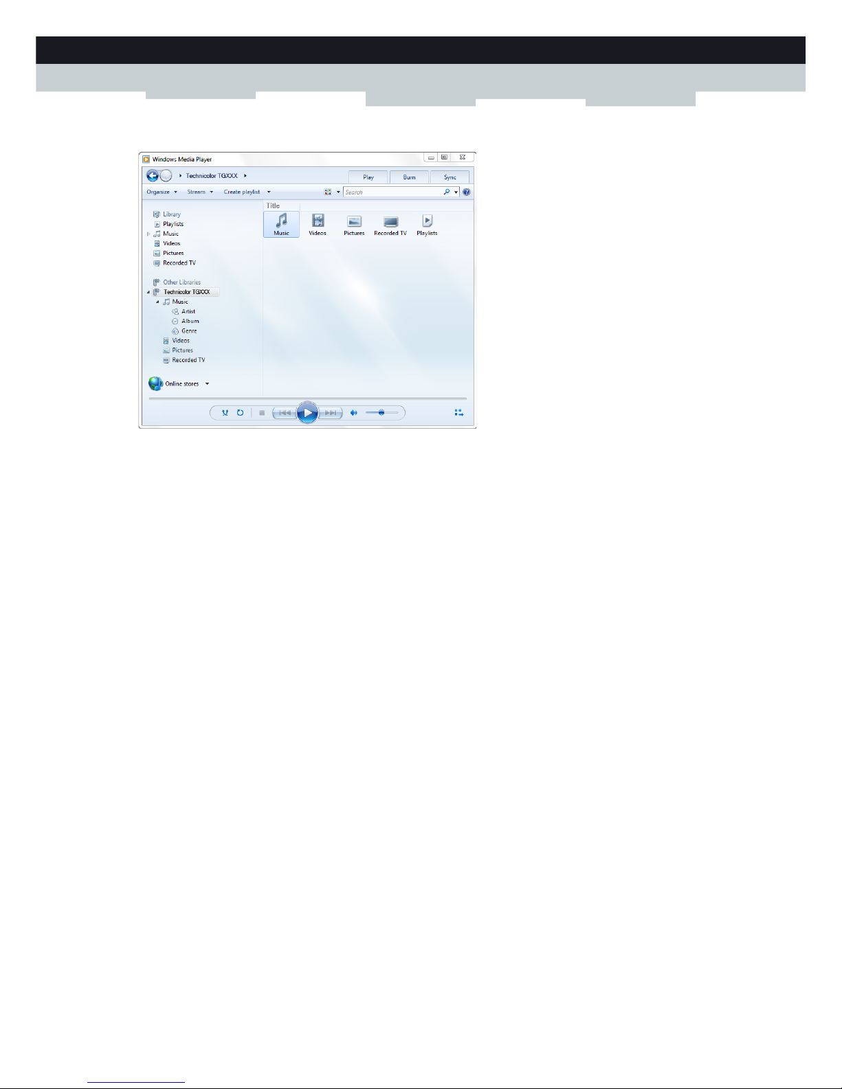
61
5 SHARING CONTENT
DMS-CTC-20111123-0002 v1.0
4Windows Media Player starts up.
Your MediaAccess Gateway’s UPnP AV Media Server is listed on the left. This entry allows you to browse to your media
files.
Page 68

62
5 SHARING CONTE
NT
DMS-CTC-20111123-0002 v1.0
5.3 The FTP Server
Introduction
The MediaAccess Gateway allows you to access your shared content by FTP. This can be useful if you want to be able to
access your shared content from the Internet.
Via FTP you can download and upload all types of files both from your local network and the Internet.
Setting up the FTP server
Proceed as follows:
1 Protect your account with a password.
2 Enable the FTP Server and select the managed partition.
Protect your account with a password
If you did not yet configure your login to the MediaAccess Gateway GUI with a password:
1 Browse to the MediaAccess Gateway GUI.
For more information, see “Accessing the MediaAccess Gateway GUI” on page 33.
2 On the Toolbox menu, click User Management.
3 In the Pick a task list, click Change my password.
4 Leave the Old Password box empty.
5 Type your new password both in the New Password box and Confirm New Password box.
Enable the FTP Server and select the managed partition
Proceed as follows:
1 Browse to the MediaAccess Gateway GUI.
For more information, see “Accessing the MediaAccess Gateway GUI” on page 33.
2 On the Tools menu, click Content Sharing.
3 In the Navigation bar, click Configure.
4 Under FTP Server, click Server Enabled.
5 Under List of connected disks, click the radio button next to the partition to make it managed.
6 The MediaAccess Gateway now creates a Media and Shared folder on the selected partition. The Shared folder will be
used as root location for FTP sessions.
7 Click Apply.
Page 69

63
5 SHARING CONTENT
DMS-CTC-20111123-0002 v1.0
Result
The Shared folder and its subfolders are now accessible using FTP. The other folders are not accessible via FTP.
If you are connected to the Internet, the link to the FTP server is displayed under FTP Server:
On the MediaAccess Gateway network, you can also access the FTP server using its local address (192.168.1.253).
Additional configuration
Because most service providers use dynamic IP addresses, the IP address of your Internet connection may change
frequently. This implies that the link to the FTP server will also change every time the public IP changes. With Dynamic
DNS, you can assign a host name to the IP address (for example mygateway.dyndns.org). For more information, see
“7.3 Dynamic DNS” on page 87.
Page 70

64
5 SHARING CONTE
NT
DMS-CTC-20111123-0002 v1.0
5.4 Managing your Shared Content
Managed Partition
If you select your drive or partition as managed partition, users only have access to the following folders:
Media
Shared
All other folders will be hidden from the user. These hidden folders are still on the USB storage device, but you can not
access them. If you connected more than one USB storage device, those devices will also be hidden.
Media folder
Use the Media folder to share your audio, video and picture files. This folder can only be accessed via the following servers:
The Network File Server
For more information, see “5.1 The Network File Server”.
UPnP AV Media Server.
For more information, see “5.2 The UPnP AV Media Server”.
Shared folder
The Shared folder is a folder to share files both on the local network and the Internet. This folder can only be accessed via
the following server:
The Network File Server
For more information, see “5.1 The Network File Server”.
FTP Server
For more information, see “5.3 The FTP Server”.
Ummanaged vs. managed
The following table compares the two modes:
Setting up the managed partition
Proceed as follows:
1 Browse to the MediaAccess Gateway GUI.
For more information, see “Accessing the MediaAccess Gateway GUI” on page 33.
2 On the Tools menu, click Content Sharing.
3 In the Navigation bar, click Configure.
If your partition is managed, the UPnP AV server will only use the media files that are located in the Media folder.
The FTP Server can only be used with a managed partition.
Access via Accessible folders
Unmanaged Managed
Network File Server All Media and Shared folder.
UPnP AV Media Server All Media folder.
FTP Server Not available in this mode. Shared folder.
Page 71

65
5 SHARING CONTENT
DMS-CTC-20111123-0002 v1.0
4 Under List of connected disks, click the radio button next to the partition you want to configure as Managed Partition.
5 Click Apply.
Result
The MediaAccess Gateway creates following folders:
Media:
Use this folder to share your media files with others users on your network. You can store your media files in following
subfolders:
Movies
Music
Pictures
Shared:
Use this folder to share your other data with other users on your network. Optionally, users can also access this folder
using FTP. For more information, see “5.3 The FTP Server” on page 62.
If the above folders already exist, the existing folders are used.
Page 72

66
5 SHARING CONTE
NT
DMS-CTC-20111123-0002 v1.0
5.5 Safely Removing your USB Storage Device
Introduction
If you just unplug your USB storage device from the MediaAccess Gateway you may loose your data. To avoid this you must
first stop your USB storage device.
Stopping your USB storage device
Proceed as follows
1 Browse to the MediaAccess Gateway GUI.
For more information, see “Accessing the MediaAccess Gateway GUI” on page 33.
2 On the Toolbox menu, click Content Sharing.
3 In the Navigation bar, click Configure.
4 Click Stop.
5 Unplug your USB storage device from the MediaAccess Gateway.
Page 73

67
6 SHARING YOUR USB PRINTER
DMS-CTC-20111123-0002 v1.0
6Sharing Your USB Printer
Introduction
A MediaAccess Gateway USB port allows you to share your USB printer in your local network. This way everyone in your
network can use the same printer without having to buy an expensive network printer.
Compatibility printer driver
The printer driver which runs on the computer must support unidirectional traffic. This is supported by the majority of
modern day printers.
Restrictions
Procedure
Proceed as follows:
1 Connect your USB printer to the MediaAccess Gateway. For more information, “6.1 Connect Your USB Printer to the
MediaAccess Gateway” on page 68.
2 Configure the printer sharing service on your MediaAccess Gateway.
For more information, see “6.2 Configuring The Printer Sharing Service on Your MediaAccess Gateway” on page 69.
3 Install the printer on your computer.
For more information, see “6.3 Installing the Printer On Your Computer” on page 71.
In case a multifunctional USB printer is connected to the MediaAccess Gateway, the non-printing services may not
work on your computer.
Only one USB printer can be connected to your MediaAccess Gateway.
Page 74

68
6 SHARING YOUR
USB PRINTER
DMS-CTC-20111123-0002 v1.0
6.1 Connect Your USB Printer to the MediaAccess
Gateway
Plug the USB cable of your printer in (one of) the USB port(s) of your MediaAccess Gateway.
Page 75

69
6 SHARING YOUR USB PRINTER
DMS-CTC-20111123-0002 v1.0
6.2 Configuring The Printer Sharing Service on Your
MediaAccess Gateway
Proceed as follows:
1 Start a CLI session on the MediaAccess Gateway.
For more information, see “3.3 The Command Line Interface (CLI)” on page 39.
2 Define the LPD printer queues with the following command:
with:
name:
Name of the queue. This name will also be used when configuring the computer.
type:
This parameter represents the type of queue:
Raw: The MediaAccess Gateway just passes through the data to the printer. In most practical situations, this is the
only queue type that will be needed.
Feed: The MediaAccess Gateway passes through the data to the printer, but an extra page feed is sent after each
completed job. This type can be used when your printer is not ejecting the last page of a print job (for example
when using clients running Linux/UNIX). This queue type is to be used in exceptional situations only and may not
be properly supported by all printers.
default:
When the parameter default is enabled, this queue will be used in case the user enters a wrong queue name. Only one
queue can be the default queue.
A typical configuration of printer queues on the MediaAccess Gateway is shown below:
3 If you want to check the configuration of printer queues on the MediaAccess Gateway, execute the following command:
4 Enable LPD printer sharing with the following command:
With:
:printersharing LPD queue add name = <string>
[type = <{Feed|Raw}>]
[default = <{no|yes}>]
:printersharing LPD queue add name=myprinter type=Raw default=yes
:printersharing LPD queue add name=myprinteronunix type=Feed default=no
You can delete queues with the command printersharing LPD queue delete name=<string>.
Before deleting a queue, make sure printer sharing is disabled.
=>:printersharing LPD queue list
LPD queue info:
name: myprinter
type: Raw
default: 1
LPD queue info:
name: myprinteronunix
type: Feed
default: 0
=>
:printersharing LPD config [state = <{disabled|enabled}>]
Page 76

70
6 SHARING YOUR
USB PRINTER
DMS-CTC-20111123-0002 v1.0
state:
With this parameter you can enable/disable LPD printer sharing.
5 If you want to check your LPD printer sharing configuration, execute the following command:
=>:printersharing LPD list
LPD printserver service:
enable: 1
=>
To make configuration changes via the CLI persistent, execute the command :saveall.
Page 77

71
6 SHARING YOUR USB PRINTER
DMS-CTC-20111123-0002 v1.0
6.3 Installing the Printer On Your Computer
Introduction
If your computer runs
Microsoft Windows 7 or Vista, continue with “6.3.1 How to install a printer on Windows 7/Vista” on page 72.
Microsoft Windows XP, continue with “6.3.2 Installing Your Printer on Windows XP” on page 74.
Mac, continue with “6.3.3 How to Install a Printer on Mac” on page 75.
Page 78

72
6 SHARING YOUR
USB PRINTER
DMS-CTC-20111123-0002 v1.0
6.3.1 How to install a printer on Windows 7/Vista
Requirements
Your computer must be connected to the MediaAccess Gateway. For more information, see “2.3 Connecting Your Network
Devices to the MediaAccess Gateway” on page 20.
Your printer has not yet been installed on your computer
In this case, proceed as follows:
1 On the Windows Start menu, click Devices and Printers.
2 On the bar on the top, click Add a printer.
3 The Add Printer Wizard appears. Select Add a local printer.
4 Select Create a new port and select Standard TCP/IP Port from the drop-down list. Click Next.
5 The Type Hostname or IP address page appears. Complete the following fields:
Hostname or IP address: enter 192.168.1.253.
Port Name: enter a name for your port (for example, Technicolor Printer Port).
Click Next.
6 The wizard now attempts to automatically detect the printer. This will take a one or two minutes.
7 The wizard prompts you that additional information is needed. Select Custom and click Settings.
8 The Configure Standard TCP/IP Port Monitor appears.
Configure the following settings:
Under Protocol, select LPR.
Under LPR Settings:
1 Type the name that you have configured in the MediaAccess Gateway in the Queue Name box (for the typical
configuration in Configuring The Printer Sharing Service on Your MediaAccess Gateway the name is myprinter).
2 Select LPR Byte Counting Enabled.
Click OK to confirm these port settings and click Next to continue in the Add Printer wizard.
9 The Install the printer driver window appears.
Select the manufacturar of your printer from the Manufacturar list and then select the printer model from the Printers
list and click Next.
10 The Type a printer name window appears.
In the Printer name box type the name that you want to give to this printer and click Next.
(Optionally) When asked if printer sharing via your computer should be enabled, select Do not share this printer and
click Next to confirm.
11 Select Print a test page to print a test page with the newly installed printer or Finish to close the Add Printer Wizard.
Your printer has already been installed on your computer
In this case you only need to create the necessary printer ports. Proceed as follows:
1 On the Windows Start menu, click Devices and Printers.
2 Right-click the printer to be shared, click Printer Properties and go to the Ports tab.
Page 79

73
6 SHARING YOUR USB PRINTER
DMS-CTC-20111123-0002 v1.0
3 Click on Add Port..., select Standard TCP/IP port and click on New Port.... The Add Standard TCP/IP Printer Port
Wizard appears. Click Next to continue.
4 In the field Printer Name or IP address, type 192.168.1.253. The Port Name is arbitrary. Click Next to confirm.
5 Select Custom and click Settings. The Configure Standard TCP/IP Port Monitor appears:
Select LPR as Protocol.
In the section LPR Settings, fill in the field Queue Name with the name that you have configured in the MediaAccess
Gateway (for the typical configuration in Configuring The Printer Sharing Service on Your MediaAccess Gateway the
name is myprinter) and select the LPR Byte Counting Enabled option.
6 Confirm these settings with OK. The Configure Standard TCP/ IP Port Monitor closes.
Click Next and Finish. The Add Standard TCP/IP Printer Port Wizard closes. The new printer port for the printer is now
created and selected for this printer.
Page 80

74
6 SHARING YOUR
USB PRINTER
DMS-CTC-20111123-0002 v1.0
6.3.2 Installing Your Printer on Windows XP
Requirements
Your computer must be connected to the MediaAccess Gateway. For more information, see “2.3 Connecting Your Network
Devices to the MediaAccess Gateway” on page 20.
Your printer has not yet been installed on your computer
If the printer is not yet installed on the computer, proceed as follows:
1 On the Windows Start menu, click (Settings>) Printers and Faxes.
2 Click (File >) Add a printer. The Add Printer Wizard appears. Click Next to continue.
3 Select Local printer attached to this computer and click Next to confirm.
4 Select Create a new port and choose Standard TCP/ IP Port from the drop-down list. Click Next to confirm.
5 The Add Standard TCP/IP Printer Port Wizard appears. Click Next to continue.
6 In the field Printer Name or IP address, type 192.168.1.253. The Port Name is arbitrary. Click Next to confirm.
7 Select Custom and click Settings. The Configure Standard TCP/IP Port Monitor appears.
Select LPR as Protocol.
In the section LPR Settings, fill in the field Queue Name with the name that you have configured in the MediaAccess
Gateway and (for the typical configuration in Configuring The Printer Sharing Service on Your MediaAccess Gateway
the name is myprinter) select the LPR Byte Counting Enabled option.
8 Confirm with OK. The Configure Standard TCP/ IP Port Monitor closes.
9 Click Next and Finish. The Add Standard TCP/IP Printer Port Wizard closes.
10 In the Add Printer Wizard, select the correct printer driver and confirm with Next.
11 Enter the Printer name and select whether or not you want to use this printer as default printer. Click Next to confirm.
(Optionally) When asked if printer sharing via your computer should be enabled, select Do not share this printer and
click Next to confirm.
12 The wizard prompts you to print a test page. Select Ye s or No and click Next when finished.
13 Click Finish to complete the installation. The printer is now installed on your computer.
Your printer has already been installed on your computer
If the printer was already previously installed on the computer, you only have to create a new printer port:
1 On the Windows Start menu, click (Settings>) Printers and Faxes.
2 Right-click the printer to be shared, select Properties and go to the Ports tab.
3 Click on Add Port..., select Standard TCP/IP port and click on New Port.... The Add Standard TCP/IP Printer Port
Wizard appears. Click Next to continue.
4 In the field Printer Name or IP address, type 192.168.1.253. The Port Name is arbitrary. Click Next to confirm.
5 Select Custom and click Settings. The Configure Standard TCP/IP Port Monitor appears:
Select LPR as Protocol.
In the section LPR Settings, fill in the field Queue Name with the name that you have configured in the MediaAccess
Gateway (for the typical configuration in Configuring The Printer Sharing Service on Your MediaAccess Gateway the
name is myprinter) and select the LPR Byte Counting Enabled option.
6 Confirm these settings with OK. The Configure Standard TCP/ IP Port Monitor closes.
7 Click Next and Finish. The Add Standard TCP/ IP Printer Port Wizard closes. The new printer port for the printer is
now created and selected for this printer.
Page 81

75
6 SHARING YOUR USB PRINTER
DMS-CTC-20111123-0002 v1.0
6.3.3 How to Install a Printer on Mac
Requirements
Your computer must be connected to the MediaAccess Gateway. For more information, see “2.3 Connecting Your Network
Devices to the MediaAccess Gateway” on page 20.
Procedure
Proceed as follows:
1 On the Apple menu, click System Preferences...
2 The System Preferences window appears. Click Print & Fax.
3 The Print & Fax window appears. Click + to add a new printer.
4 The Printer Browser window appears. Enter the following settings:
Protocol: Line Printer Daemon - LPD
Address: Type 192.168.1.253.
Queue: The name that you have configured in the MediaAccess Gateway. If you leave this field blank, the default
queue will be used if configured (for the typical configuration in Configuring The Printer Sharing Service on Your
MediaAccess Gateway the name is myprinter).
Name: Enter a name of your choice to your printer or leave default value.
Location: Enter a location or leave blank.
Print using: Select a printer model or leave the default value.
5 Click Add.
6 The printer is now installed on your computer.
Page 82

76
6 SHARING YOUR
USB PRINTER
DMS-CTC-20111123-0002 v1.0
Page 83

77
7 NETWORK SERVICES
DMS-CTC-20111123-0002 v1.0
7Network Services
In this chapter
In this chapter we will take a closer look at following features:
Feature availability
Depending on the configuration offered by your service provider, some features may not be available on your MediaAccess
Gateway. For more information, contact your service provider.
To p i c Page
7.1 U Pn P 78
7.2 Assigning a service (HTTP, FTP,...) to a Computer 85
7.3 Dyna mi c DNS 87
“7.4 Network Time Server” on page 88 88
Page 84

78
7 NETWORK SERVI
CES
DMS-CTC-20111123-0002 v1.0
7.1 U Pn P
Introduction
UPnP is designed to automate the installation and configuration of a (small) network as much as possible. This means that
UPnP-capable devices can join and leave a network without any effort of a network administrator.
Supported Operating Systems
The following operating systems support UPnP:
Windows 7
Windows Vista
Windows XP
UPnP and the MediaAccess Gateway
UPnP offers you the following functions:
You can access the MediaAccess Gateway GUI without having to remember the address of the MediaAccess Gateway.
For more information, see “7.1.1 Accessing Your MediaAccess Gateway via UPnP” on page 79.
If you are using a PPP connection to connect to the Internet, you can enable/disable your Internet connection without
having to open the MediaAccess Gateway GUI.
For more information, see “7.1.2 Managing your Internet connection via UPnP” on page 80.
You do not have to manually create port mappings to run services on a computer. The automatic port configuration
mechanism for UPnP-enabled games and applications will do this for you. If the application is UPnP-enabled, UPnP will
create these entries automatically. For more information, see “7.2 Assigning a service (HTTP, FTP,...) to a Computer” on
page 85.
If your computer is running Windows XP, you first have to install the UPnP component. For more information, see
“7.1.4 Installing UPnP on Windows XP” on page 83.
Page 85

79
7 NETWORK SERVICES
DMS-CTC-20111123-0002 v1.0
7.1.1 Accessing Your MediaAccess Gateway via UPnP
Windows 7/ Vista
If you computer runs Windows 7/ Vista:
1 On the Windows Start menu, click Network.
2 The Network window appears:
3 Right-click your MediaAccess Gateway (displayed as Technicolor TGXXX) and click View device web page.
4 The MediaAccess Gateway GUI appears.
Windows XP
If you computer runs Windows XP:
1 Go to My Network Places.
2 The My Network Places window appears:
3 Double-click your MediaAccess Gateway (displayed as Technicolor TGXXX).
4 The MediaAccess Gateway GUI appears.
Page 86

80
7 NETWORK SERVI
CES
DMS-CTC-20111123-0002 v1.0
7.1.2 Managing your Internet connection via UPnP
Applicability
This section only applicable if you are using a PPP connection to the Internet.
Windows 7/ Vista
If you computer runs Windows 7/ Vista:
1 On the Windows Start menu, click Network.
2 The Network window appears:
3 Right-click your MediaAccess Gateway (displayed as Technicolor TGXXX).
4 If you are currently:
Connected to the Internet, click Disable to disconnect from the Internet.
Not connected to the Internet, click Enable to connect to the Internet.
Windows XP
Proceed as follows:
1 On the Windows Start menu, click (Settings >) Control Panel.
2 The Control Panel window appears.
Click (Network and Internet Connections) > Internet Connections.
Page 87

81
7 NETWORK SERVICES
DMS-CTC-20111123-0002 v1.0
3 The Network Connections window appears;
4 If you right-click the Internet Connection icon, you can connect/disconnect your connection to the Internet.
Disabling this feature
To prevent that users can connect/disconnect you can enable Extended Security. This feature is enabled by default.
For more information, see “7.1.3 Configuring UPnP on the MediaAccess Gateway” on page 82.
Page 88

82
7 NETWORK SERVI
CES
DMS-CTC-20111123-0002 v1.0
7.1.3 Configuring UPnP on the MediaAccess Gateway
Introduction
On the MediaAccess Gateway GUI you can:
Enable/Disable UPnP.
Enable/Disable Extended Security.
Enable/Disable UPnP
Proceed as follows:
1 Browse to the MediaAccess Gateway GUI.
For more information, see “Accessing the MediaAccess Gateway GUI” on page 33.
2 On the Toolbox menu, click Game & Application Sharing.
3 Under Universal Plug and Play:
Select the Use UPnP check box, to enable UPnP.
Clear the Use UPnP check box, to disable UPnP.
4 Click Apply.
Extended Security
If Extended Security is enabled, only limited UPnP operation between the host and the MediaAccess Gateway is allowed:
A local host is not allowed to connect/disconnect the MediaAccess Gateway Internet connection. You can then only
connect/disconnect the Internet connection via the MediaAccess Gateway GUI
Address translation mappings can only be added or changed via UPnP for the host on which the UPnP application is
running.
Extended Security is enabled by default.
Enable/Disable Extended Security
Proceed as follows:
1 Browse to the MediaAccess Gateway GUI.
For more information, see “Accessing the MediaAccess Gateway GUI” on page 33.
2 On the Toolbox menu, click Game & Application Sharing.
3 Under Universal Plug and Play, select Use Extended Security.
4 Click Apply.
Page 89

83
7 NETWORK SERVICES
DMS-CTC-20111123-0002 v1.0
7.1.4 Installing UPnP on Windows XP
Adding UPnP
If you are running Microsoft Windows XP, it is recommended to add the UPnP component to your system.
Proceed as follows:
1 In the Start menu, click (Settings >) Control Panel.
2 The Control Panel window appears.
Click Add or Remove Programs.
3 The Add or Remove Programs window appears.
Click Add/Remove Windows Components.
4 The Windows Components Wizard appears:
In the Components list, select Networking Services and click Details
5 The Networking Services window appears:
Select Universal Plug and Play or UPnP User Interface and click OK.
6 Click Next to start the installation and follow the instructions in the Windows Components Wizard.
7 At the end of the procedure the wizard informs you that the installation was successful. Click Finish to quit.
Adding IGD Discovery and Control
Your Windows XP system is able to discover and control Internet Gateway Devices (IGD), like the MediaAccess Gateway
on your local network. Therefore, it is recommended to add the IGD Discovery and Control client to your system.
Proceed as follows:
1 On the Windows taskbar, click Start.
Page 90

84
7 NETWORK SERVI
CES
DMS-CTC-20111123-0002 v1.0
2 Select (Settings >) Control Panel > Add or Remove Programs.
3 In the Add or Remove Programs window, click Add/Remove Windows Components.
4 The Windows Components Wizard appears:
Select Networking Services in the Components list and click Details.
5 The Networking Services window appears:
Select Internet Gateway Device Discovery and Control Client and click OK.
6 Click Next to start the installation and follow the instructions in the Windows Components Wizard.
7 At the end of the procedure, the wizard informs you that the installation was successful. Click Finish to quit.
Page 91

85
7 NETWORK SERVICES
DMS-CTC-20111123-0002 v1.0
7.2 Assigning a service (HTTP, FTP,...) to a Computer
Introduction
The MediaAccess Gateway allows you to use one Internet connection for multiple computers. This means that all your
computers share one public IP address, as if only one computer were connected to the outside world.
Issue
When the MediaAccess Gateway receives an incoming message, the MediaAccess Gateway has to decide to which
computer it has to send this message.
If the incoming message is a response to an outgoing message originating from one of your computers, the MediaAccess
Gateway sends the incoming message to this computer.
If your are running a server or an application that acts as a server (for example a HTTP server, Internet game), the initial
message will come from the Internet and the MediaAccess Gateway has no information to decide to which computer it
should forward the incoming message.
Solution
To avoid this problem you can do either of the following:
Enable UPnP.
Assign a game or application to a local networking device.
UPnP
UPnP is a technology that enables seamless operation of a wide range of games and messaging applications. Your computer
will use UPnP to communicate to the MediaAccess Gateway which services are running on the computer.
For example, when you start a UPnP-enabled application on your computer, it will automatically create the necessary port
mappings on this computer and on the MediaAccess Gateway.
For more information on UPnP, see “7.1 UPnP” on page 78.
Internet
Internet
?
Page 92

86
7 NETWORK SERVI
CES
DMS-CTC-20111123-0002 v1.0
Assign a game or application to a local networking device
If you assign a game or application to a local networking device, you will basically tell the MediaAccess Gateway that if it
receives requests for a specific game or application, it has to forward these messages to a specific computer.
Proceed as follows to do so:
1 Browse to the MediaAccess Gateway GUI.
For more information, see “Accessing the MediaAccess Gateway GUI” on page 33.
2 On the Toolbox menu, click Game & Application Sharing.
3 In the Pick a task list, click Assign a game or application to a local network device.
4 In the Game or application list, click the service you want to run on the computer. For example, HTTP Server (World
Wide Web).
5 In the Device list, select the computer to which you want to assign the service. Your computer will be listed with its
computer name.
6 All incoming requests for the selected service will now be directed to the selected device. The MediaAccess Gateway will
also configure its firewall to allow this service.
If the service is not available in the list, click Create a new game or application in the Pick a task list. For more
information, click Help on the MediaAccess Gateway GUI.
Page 93

87
7 NETWORK SERVICES
DMS-CTC-20111123-0002 v1.0
7.3 Dyna mic DNS
Introduction
The Dynamic DNS service allows you to assign a dynamic DNS host name (for example mywebpage.dyndns.org) to a
broadband connection even if it is using a dynamic IP address. As soon as the device gets a new IP address, the dynamic
DNS server updates its entry to the new IP address.
What you need
Before you can configure Dynamic DNS, you first have to create an account at a Dynamic DNS service provider. For
example:
www.dyndns.org
www.no-ip.com
www.dtdns.com
Procedure
Proceed as follows:
1 Browse to the MediaAccess Gateway GUI.
For more information, see “Accessing the MediaAccess Gateway GUI” on page 33.
2 On the Toolbox menu, click Dynamic DNS.
3 On the Navigation bar, click Configure.
4 Select the Enabled check box.
5 If necessary, select the broadband connection to which you want to assign the Dynamic DNS host name in the Interface
list.
6 Type the user name and password of your Dynamic DNS service account in the corresponding fields.
7 In the Service list, click the name of your Dynamic DNS service provider.
8 In the Host box, type the host name that you got from the Dynamic DNS service provider (for example
mywebpage.dyndns.org).
9 Click Apply.
Page 94

88
7 NETWORK SERVI
CES
DMS-CTC-20111123-0002 v1.0
7.4 Network Time Ser ver
Introduction
A Network Time Server is a server that makes sure that the time settings of your device (your MediaAccess Gateway) are
in sync with the official time.
This time will be used for features like:
Event logs
IPSec
SNMP
Requirements
Your MediaAccess Gateway must be connected to the Internet.
Specifying a time server for your MediaAccess Gateway
Proceed as follows:
1 Browse to the MediaAccess Gateway GUI.
For more information, see “Accessing the MediaAccess Gateway GUI” on page 33.
2 On the Technicolor Gateway menu, click Configuration.
3 The System Configuration page appears. On the Navigation bar, click Configure.
4 Under Time Configuration, select Auto-configuration and configure the following settings:
Page 95

89
8 INTERNET SECURITY
DMS-CTC-20111123-0002 v1.0
8 Internet Security
Overview
The MediaAccess Gateway offers various options to secure your network and network connection:
To p i c Page
8.1 IPSec and VPN 90
8.2 Web Site Filtering 91
8.3 Firewall 96
Page 96

90
8 INTERNET SECUR
ITY
DMS-CTC-20111123-0002 v1.0
8.1 IPSec and VPN
What Is a VPN?
A VPN or Virtual Private Network is a private communications network set up over a publicly accessible network. A VPN
creates a kind of tunnel through which information is transported between a computer and the network to which it is
connected.
What Is IPSec?
IP Security (IPSec) is a way of securing communication over IP. IPSec is used to create a VPN. It allows you to connect your
local computer to the remote network in a safe way as it provides:
Reliable user authentication.
Reliable tunnel encryption able to cope with existing network and firewall settings.
IPSec and VPN on your MediaAccess Gateway
Your MediaAccess Gateway has integrate has an integrated IPSec/VPN client and server allowing you to setup the
following scenarios configure the most common VPN scenarios, for example:
LAN-to-LAN connection
VPN Client configuration
VPN Server configuration
LAN-to-LAN
The MediaAccess Gateway allows you to connect LAN networks that are located on different sites via a secure VPN tunnel
over the public Internet. At each peer the MediaAccess Gateway acts as an IPSec security gateway.
VPN Client
The VPN client in the MediaAccess Gateway can replace a software VPN client installed on a computer. You can use it for
example to connect from your home to the corporate network for teleworking.
Using the VPN client in the MediaAccess Gateway has several advantages over the use of VPN client software installed on
the computer of the end user:
The administrator of the corporate network does not have to worry about upgrades of the operating system on the
teleworker’s computer.
Since the VPN client is fully integrated in the MediaAccess Gateway, it can not be tampered with, and is probably more
secure than software residing on a computer.
Adverse interactions with computer software, such as firewalls, PPPoE clients, wireless drivers, viruses and worms are
avoided. This guarantees a better stability and fewer functionality problems.
VPN Server
The MediaAccess Gateway can establish a secure connection with any remote gateway that meets the VPN settings,
regardless its location in the public network. The use of the Extended Authentication protocol can optionally be configured.
In this case, a list of authorized users is composed and stored on the MediaAccess Gateway.
More information
In-depth information about the different scenarios and configuration can be found in the MediaAccess Gateway IPSec
documentation available at www.technicolor.com
.
Page 97

91
8 INTERNET SECURITY
DMS-CTC-20111123-0002 v1.0
8.2 Web Site Filtering
Introduction
The MediaAccess Gateway allows you to deny access to specific web sites.
Access Denied page
When a user tries to access a page that is being blocked, the following page is displayed:
Address-based filtering
With address-based filtering (or URL-filtering) you can block web sites based on their address (for example
www.porn.com).
Content-based filtering
As you know, the Internet consists of a large number of web sites, and that number still increases every day. This makes it
almost impossible to keep the list of addresses up-to-date.
To solve this problem MediaAccess Gateway introduced content-based filtering.
With content-based filtering you can block web sites based on their content category (for example pornography) instead
of their URL. This way, you only need to select the appropriate categories and the content category server takes care of the
rest. This content category server is updated at regular intervals.
Combining the two filters
Address-based filtering has priority over content-based filtering. This means that when you are blocking a specific
category, you can still access a specific address provided you create a rule to allow access to that URL.
For example, if you are blocking content from the Finance / Investment category, you can create a rule to make an
exception for netbanking.mybank.com.
Activating content-based filtering
Before you can use content-based filtering you must first activate it by purchasing a license key at your service provider or by
activating the 30-day trial.
Proceed as follows:
1 Browse to the MediaAccess Gateway GUI.
For more information, see “Accessing the MediaAccess Gateway GUI” on page 33.
2 On the Toolbox menu, click Web Site Filtering.
3 In the Pick a task list, click Activate Web Filtering License.
4 The Web Filte ri ng Activation page appears. Under License Type, select:
30-days evaluation if you first want evaluate this feature.
Standard if you have already purchased a license key. The License key box appears as soon as you select this option.
Type the license key that you received from your service provider in this box.
5 Click Apply.
Page 98

92
8 INTERNET SECUR
ITY
DMS-CTC-20111123-0002 v1.0
Option 1: content-based filter (combined with the address-based filter)
If you want to use the content-based filtering:
1 Browse to the MediaAccess Gateway GUI.
For more information, see “Accessing the MediaAccess Gateway GUI” on page 33.
2 On the Toolbox menu, click Web Site Filtering.
3 On the Navigation bar, click Configure.
4 Make sure that the Use Content-Based Filter check box is selected.
5 Configure the content-based filter. For more information, see “8.2.1 Configuring Content-based Filtering” on page 93.
6 If you want to make exceptions for specific web sites, add the necessary rules in the address-based filter. For more
information, see “8.2.2 Adding Rules for Address-Based Filtering” on page 94.
Option 2: address-based filter only
Take this option if content filtering is not available on your MediaAccess Gateway or you don’t want to use it.
To configure address-based filtering:
1 Browse to the MediaAccess Gateway GUI.
For more information, see “Accessing the MediaAccess Gateway GUI” on page 33.
2 On the Toolbox menu, click Web Site Filtering.
3 On the Navigation bar, click Configure.
4 Make sure that the Use Address-Based Filter check box is selected.
5 In the Action for Unknown Sites, select:
Allow as the default rule if you want to allow access to all web sites and manually specify which web sites may not be
accessed.
Block as the default rule if you want to deny access to all web sites and manually specify a number of web sites that
may be accessed.
6 Click Apply.
7 If you want to make exceptions for specific web sites, add the necessary rules in the address-based filter.
For more information, see “8.2.2 Adding Rules for Address-Based Filtering” on page 94.
Page 99

93
8 INTERNET SECURITY
DMS-CTC-20111123-0002 v1.0
8.2.1 Configuring Content-based Filtering
Requirements
Content-based filtering must be activated on your MediaAccess Gateway.
For more information, see “Activating content-based filtering” on page 91.
Accessing the configuration page
Proceed as follows:
1 Browse to the MediaAccess Gateway GUI.
For more information, see “Accessing the MediaAccess Gateway GUI” on page 33.
2 On the Toolbox menu, click Web Site Filtering.
3 On the Navigation bar, click Configure.
4 Under Content-Based Filtering you can change the settings of the content-based filter.
Configuration
Under Content-Based Filtering:
1 Select Use Content-Based Filter check box (if needed).
2 In the Action for uncategorised sites list, select a default action for sites that have not yet been categorised.
3 Under Content Level, select the content level you want to use.
If you want a more detailed view of the content that will be blocked for this level, click the Edit link next to the content
level.
If needed, you can change the Name, Description and Configuration of the content level.
4 Click Apply after you have made your changes.
Creating your own content level
Proceed as follows:
1 In the Pick a task list, click Create a new content level.
2 Enter a Name and Description for your content level and click Next.
3 Under Configuration, select:
Clone Existing Level if you want to start from an existing level. You can now select the level that you want to clone.
White list if you want to block everything and select which content should be allowed.
Black list if you want to allow everything and select which content should be blocked.
Click Next.
4 Under Configuration:
Select the check boxes of the categories/groups you want to allow.
Clear the check boxes of the categories/groups you want to block.
5 Click Apply.
6 Configure the content-based filter with the new level. For more information, see “Configuration” on page 93.
Page 100

94
8 INTERNET SECUR
ITY
DMS-CTC-20111123-0002 v1.0
8.2.2 Adding Rules for Address-Based Filtering
Introduction
Address-based filtering has a higher priority than content-based filtering. This means that when you are blocking a specific
category, you can still access a specific site if you allow it in the address-based filter.
Example
If you block content from the Finance / Investment category and allow access to netbanking.mybank.com,
netbanking.mybank.com will still be accessible.
Options
With the address-based filter you can:
Deny access to a specific web site.
Allow access to a specific web site.
Redirect a web site.
Redirect all web sites.
Deny access to a specific web site
Proceed as follows:
1 Browse to the MediaAccess Gateway GUI.
For more information, see “Accessing the MediaAccess Gateway GUI” on page 33.
2 On the Toolbox menu, click Web Site Filtering.
3 Make sure the Use Address-Based Filter check box is selected.
4 Type the URL of the Web site you want to block (for example “mail.provider.com”) in the Web Site box.
5 In the Action list, click Block.
6 Click Add.
Allow access to a specific web site
Proceed as follows:
1 Browse to the MediaAccess Gateway GUI.
For more information, see “Accessing the MediaAccess Gateway GUI” on page 33.
2 On the Toolbox menu, click Web Site Filtering.
3 Make sure the Use Address-Based Filter check box is selected.
4 Type the URL of the Web site you want to allow (for example “netbanking.bank.com”) in the Web Site box.
5 In the Action list, click Allow.
6 Click Add.
Redirect a web site
Proceed as follows:
1 Browse to the MediaAccess Gateway GUI.
For more information, see “Accessing the MediaAccess Gateway GUI” on page 33.
2 On the Toolbox menu, click Web Site Filtering.
3 Make sure the Use Address-Based Filter check box is selected.
4 Type the URL of the Web site you want to redirect (for example “cracks.am”) in the Web Site box.
 Loading...