

Page 1

1
SERVICE MANUAL
PHRIE / PHIE
INVERTER MONOBLOCK
AIR TO WATER HEAT PUMP
MEDIUM TEMPERATURE
Refrigerant R410A
For applications with electrical support heater or boiler back-up
Jun. 2015 10 12 211 – GB – 06
Page 2

2
Page 3

3
WARNING:
Before carrying out any work on the machine, make sure that its power supply is switched off and the access to it
is prevented. Any work must be carried out by personnel qualified and authorized to work on this type of machine.
Page 4

4
▬ CONTENTS ▬
1 SPECIFICATIONS
1.1 Application - Use
1.2 Presentation & Components
1.3 Technical characteristics
1.4 Physical characteristics
1.5 Description
1.6 Heat pumps capacities
1.7 Available pressures on water circuit
1.8 Sound levels
1.9 System control solutions
2 FRIGORIFIC & HYDRAULIC PART - DIAGRAMS / MAIN COMPONENTS
2.1 Frigorific & Hydraulic diagrams
2.2 Frigorific circuit – Main components description
2.3 Hydraulic circuit – Main components description
3 ELECTRICAL PART - DIAGRAMS / MAIN COMPONENTS
3.1 Diagrams
3.2 Main components
4 SPECIFIC FUNCTIONS ON INVERTER CONTROL
4.1 Water temperature control
4.2 Compressor frequency control
4.3 Max & Min frequency control
4.4 Current release control
4.5 Cooling high-load prevention control
4.6 Heating high-load prevention control
4.7 Freeze prevention control in cooling mode
4.8 Discharge temperature control
4.9 Air heat exchanger defrost control
4.10 Fan control
4.11 Electronic expansion valve control
4.12 Water circulating pump control
4.13 Water flow monitoring
4.14 Heat pump base de-ice heater control
4.15 Heat pump outgoing water temperature alarm
4.16 Heat pump stand alone operation
4.17 Heat pump alarm signal for system control
Page 5

5
5 SERVICE PROCEDURES
5.1 Frigorific circuit alarms
5.2 Hydraulic circuit alarms
5.3 System control alarms
5.4 Boards replacement
5.5 Sensors characteristics
5.6 Electric heater replacement for units 095 & 125
6 MAINTENANCE CONTROLLER FUNCTIONS - PARAMETERS
6.1 Presentation
6.2 Standard display and settings - Connection to A2 control board
6.3 Advanced display and setting - Connection to A3 power board
Page 6

6
PART 1 – TECHNICAL SPECIFICATION
1.1 Application - Use
1.2 Presentation & Components
1.3 Technical characteristics
1.4 Physical characteristics
1.5 Description
1.6 Heat pumps capacities
1.7 Available pressures on water circuit
1.8 Sound levels
1.9 System control solutions
Page 7
7
1.1 – APPLICATION - USE
• Hot water generator for residential heating exclusively in the scope of TECHNIBEL systems
1.2 – PRESENTATION & COMPONENTS
1.2.1 DESCRIPTION
Page 8

8
1.2.2 ELECTRICAL EQUIPEMENT
• According EN 60 335-2-40.
• INVERTER technology control
• Staged electric support heater (with thermal overload protection and water pressure switch).
• Water flow detector.
• System control board.
Page 9

9
1.3 – TECHNICAL CHARACTERISTICS
The specifications are valid for a device in working order with clean heat exchanger.
Note:
• Water circuit pressure: Minimum = 1.5bar,
Maximum = 2.5Bar.
• Maximum allowable water temperature at the inlet of the heat pump when off is 75°C.
• System water volume: see §. 1.5.
• Available water pressure: see §. 1.7.
• Sound level: see §. 1.8.
1.3.1 SINGLE PHASE MODELS
Page 10

10
Page 11

11
Page 12

12
1.3.2 THREE PHASES MODELS
Page 13

13
Page 14

14
Page 15

15
Page 16

16
1.3.3 OPERATING LIMITS
• Automatic devices of the control reduce or prohibit operation of the appliance outside the following limits.
HEATING MODE OPERATING LIMITS:
Page 17

17
1.4 – PHYSICAL CHARACTERISTICS
Page 18

18
Page 19

19
1.5 – DESCRIPTION
1.5.1 SINGLE PHASE MODELS
Page 20

20
1.5.2 THREE PHASES MODELS
Page 21

21
1.6 – HEAT PUMP CAPACITIES
1.6.1 HEATING / COOLING CAPACITIES
See technical manual 10 12 202
1.6.2 CAPACITY CORRECTION ACCORDING GLYCOL RATIO
IMPORTANT: Use monopropylen glycol. A minimum rate of 15 to 20% is needed to avoid any risk of corrosion.
Curves use principle:
Choose the percentage of glycol according to the minimum temperature in order to protect the hydraulic circuit against frost and
then determine the coefficients to be applied to the capacity of the unit, the water flow rate and the pressure drop.
Cooling Mode:
Heating mode:
For current applications, the impact of glycol ratio can be ignored.
1.7 – AVAILABLE PRESSURES ON WATER CIRCUIT
These available pressures are indicated for the water flow to be set at the installation, according to the maximum water outlet
temperature (which is determined according to the application).
Please refer to part 3 for water flow setting.
Example:
-Protection at a outdoor temperature of -15°C gives 30%
glycol (“freezing point curve”).
-This percentage of glycol induces:
• A reduction coefficient of cooling capacity of 0.94.
• A water flow rate coefficient of 1.113 (flow must be
increased).
• A water pressure drop coefficient of 1.19 to be
applied for pressure drop calculation.
Page 22

22
Page 23

23
Page 24

24
Model
Power
level
Lw (dBA
)
Sound-pressure
level (dBA)
Max.
capacity
Puissance
maximum
Nominal
capacity
Max.
capacity
PHRIE 095
PHIE 095
65 67
37 39
PHRIE 125
PHIE 125
65 67
37 39
PHRIE 155
PHIE 155
66 70
38 42
PHRIE 157
PHIE 157
66 70
38 42
PHRIE 175
PHRIE 177
68 72
40 44
PHRIE 195
PHRIE 197
70 74
41 45
PHRIE 257
PHRIE 307
68 72
40 44
1.8 – SOUND LEVELS
Reference standard:
Measurements as per standard EN 12 102.
Measuring method: reverberating chamber
Sound-pressure level:
Unit installed outdoors (free field) on a reflective
surface.
Measurement carried out at a distance of 10m.
Silent mode:
It is possible to activate a silent-mode on the unit.
In this case, the compressor speed is limited for
the nominal capacity of the unit.
For details, see part 4.
Page 25

25
Sound power level spectrum:
Tests conditions:
-Unit at nominal capacity
-Air temperature: 7°C (DB)
-Water inlet temperature: 47°C
-Water outlet temperature:55°C
PHRIE 95
frequency (Hz) Lw dB(A)
100 38,3
125 35,6
160 48,4
200 51,4
250 46,3
315 59,2
400 53,2
500 48,6
630 51,1
800 55,6
1000 55,8
1250 55,3
1600 51,2
2000 45,7
2500 52,8
3150 48,2
4000 48,7
5000 46,6
6300 42,2
8000 37,5
10000 36,7
Sound power level 65,0
PHRIE 125
frequency (Hz) Lw dB(A)
100 44,4
125 41,5
160 42
200 50,5
250 51,3
315 47,7
400 62,3
500 54,2
630 51,5
800 54,5
1000 50,4
1250 47,8
1600 46,4
2000 44,5
2500 46,6
3150 49,8
4000 42,3
5000 38,6
6300 37,3
8000 33,9
10000 28,3
Sound power level 65,0
Page 26

26
PHRIE 155
frequency (Hz) Lw dB(A)
100 52,4
125 49,7
160 53,3
200 55,8
250 46,7
315 46,8
400 49,2
500 54,9
630 60,7
800 59,3
1000 53
1250 48,2
1600 43,2
2000 46,9
2500 46,5
3150 48,1
4000 46,8
5000 47,2
6300 44,5
8000 39
10000 37,7
Sound power level 66,0
PHRIE 175
frequency (Hz) Lw dB(A)
100 57,6
125 52,6
160 53,5
200 54,4
250 51,2
315 50,5
400 52,9
500 56,1
630 62,2
800 61,6
1000 55,2
1250 51,6
1600 48,3
2000 50,0
2500 49,4
3150 51,0
4000 49,8
5000 48,5
6300 45,6
8000 39,5
10000 38,1
Sound power level 68,0
PHRIE 195
frequency (Hz) Lw dB(A)
100 62,4
125 55
160 53,3
200 52,6
250 55,2
315 53,7
400 56,1
500 56,9
630 63,3
800 63,4
1000 56,9
1250 54,5
1600 53
2000 52,7
2500 51,9
3150 53,5
4000 52,4
5000 49,3
6300 46,3
8000 39,5
10000 38
Sound power level 70,0
Page 27

27
PHRIE 257
frequency (Hz) Lw dB(A)
100 52,7
125 44,3
160 50,1
200 48,5
250 50,2
315 57,8
400 55,8
500 56,3
630 62,4
800 61,9
1000 54,2
1250 53,5
1600 53,7
2000 51,3
2500 49,3
3150 50,8
4000 49,7
5000 44,2
6300 43,1
8000 38,4
10000 37,4
Sound power level 68,0
PHRIE 307
frequency (Hz) Lw dB(A)
100 51,1
125 50,8
160 52,9
200 53,7
250 52,4
315 54,4
400 56,3
500 57,5
630 61,1
800 60,3
1000 57,7
1250 55,9
1600 54
2000 53,1
2500 51,5
3150 50,9
4000 49,4
5000 47,9
6300 44,7
8000 39,9
10000 37,5
Sound power level 68,0
Page 28

28
1.9 – SYSTEM CONTROL SOLUTIONS
It features 2 parts:
- Monitoring / control assembly with INVERTER technology, for the
thermodynamic
device. Built into the heat pump, it
controls:
- The variable-speed compressor.
- The variable-speed fan.
- The electronic expansion valve and the cycle inversion valve.
- The water circulating pump (with frost protection and anti-sticking functions).
- System monitoring and control assembly. It ensures:
- Thermodynamic heating control with permanent control of the required capacity based on the needs of the
installation.
- Control of the supplementary support heating.
- Control of the circulators.
- Management of the installation safeties and alarms.
A system control kit must be ordered separately - 2 possibilities:
• For standard applications with integrated electric support heater : system control kit K60D070Z
• For applications with boiler back-up: system control kit K60D071Z
9 System control kit K60D070Z
For standard applications using heat pump with
integrated electric heater
:
A
PPLICATIONS
K60D070ZA. K60D070ZB.
- 1 Floor Zone
- 2 floor Zones
- 1 Terminal Units Zone
- 1 Radiators Zone
- 2 Mixed Zones; Floor + Terminal Units
- 2 Mixed Zones; Floor + Radiators
- 1 Radiators zone + Domestic Hot Water tank
Until mid 2012
- 1 Floor Zone + Domestic Hot Water tank
- 1 Radiators Zone + Domestic Hot Water tank
Since mid 2012, extension B has been dedicated to
applications with Domestic Hot Water
For all details concerning system control operation, please refer to the corresponding technical manuals:
Technical manual 10 12 200 Technical manual 10 12 204
9 System control kit K60D071Z
For applications with boiler back-up:
- 1 Floor Zone
System control kit includes:
- system remote control box,
- outdoor temperature sensor,
- system control manuals.
Page 29

29
- 1 Radiators Zone
For all details concerning system control operation, please refer to the corresponding technical manual 10 12 201
Note: With both system controls, for 1 Zone applications, possibility to activate a 2nd zone with electric convectors. These
appliances must be equipped with an electronic thermostat (out of supply) able to receive controls signals
by means of a
230Vac pilot wire (according standard GIFAM 4).
System control kit includes:
- system remote control box,
- outdoor temperature sensor,
- system control cabinet,
(to be installed in a sheltered technical room)
- system water temperature sensors,
- system control manuals.
Page 30

30
PART 2 – FRIGORIFIC & HYDRAULIC
2.1 Frigorific / Hydraulic diagrams
2.2 Frigorific circuit – Main components description
2.2.1 Compressor
2.2.2 Electronic expansion valve
2.2.3 Four way valve
2.2.4 Fan motor
2.2.5 Pressure sensor
2.3 Hydraulic circuit – Main components description
2.3.1 Water circulating pump
2.3.2 Water flow switch
2.3.3 Pressurized expansion vessel
2.3.4 Safety relief valve
Page 31

31
2.1 – FRIGORIFIC / HYDRAULIC DIAGRAMS
2.1.1 DIAGRAMS FOR MODELS 095/125/155/157/175/177/195/197
Page 32

32
2.1.2 DIAGRAMS FOR MODELS 257/307
Page 33

33
2.2 – FRIGORIFIC CIRCUIT – MAIN COMPONENTS DESCRIPTION
2.2.1 COMPRESSOR
CONTENT
Unit
095 125 155 157 175 177 195 197 257 307
Type
SANYO Hermetic rotary compressor
Reference
C-6RVN93
H0R
C-6RVN103
H0S
C-9RVN273
H0M
C-9RVN273
H0K
C-9RVN273
H0M
C-9RVN273
H0K
C-9RVN273
H0M
C-9RVN273
H0K
C-9RVN273
H0K
C-9RVN393
H0U
Rated output W 900 1000 2700 2700 2700 2700 2700 2700 2700 3900
Comp. Cooling natural
Power source DC inverter
Voltage V 132V 124V 150V 246V 150V 246V 150V 246V 246V 282V
Refrigerant R410A
Oil type DAPHNE FV68S or equivalent
Oil volume L 0.35 0.6 1.4 1.4 1.4 1.4 1.4 1.4 1.4 1.9
Motor type DC Brushless motor
Number of poles 4
Insulation class E
Coil resistance T-R (*) Ω 0.482 0.452 0.169 0.552 0.169 0.552 0.169 0.552 0.552 0.608
Coil resistance T-S (*) Ω 0.482 0.452 0.169 0.552 0.169 0.552 0.169 0.552 0.552 0.608
Coil resistance T-S (*) Ω 0.482 0.452 0.169 0.552 0.169 0.552 0.169 0.552 0.552 0.608
Thermistor sensor Discharge temperature sensor
Cranckase heater _ _ _ _ _ _ _ _ 28W
240V
28W
240V
(*) at 25°C
Refrigerant charge
In the heat pump
Kg 1.8 1.9 3.5 3.5 3.8 3.8 4.2 4.2 5.8 6.5
Connection diagram for 095 :
Connection diagram for 125 :
Page 34

34
Connection diagram for 155/175/195 :
Connection diagram for 157/177/197/257/307 :
(257/307)
Page 35

35
2.2.2 ELECTRONIC EXPANSION VALVE
CONTENT UNIT 095 125 155 157 175 177 195 197 257 307
Type SAGINOMIYA type KV Electronic Expansion Valve – bi-flow
Reference UKV 18D UKV 25D
Motor Permanent magnet type direct operating stepper motor – 480 steps
Coil supply V dc 12 Vdc
Insulation class E
Enclosure IP 66
Motor reference UKV
A053
UKV
U030
UKV
A053
UKV
U030
UKV
A053
UKV
U030
UKV
A053
UKV
A053
Motor checking – to be done with ohmmeter on motor disconnected
Between wires Resistance
Between wires Resistance
Grey (common) Orange (A) 46 +/-3 Ω Grey (common A) Orange (A) 46 +/-3 Ω
Grey (common) Yellow (non A) 46 +/-3 Ω Grey (common A) Yellow (non A) 46 +/-3 Ω
Grey (common) Red (B) 46 +/-3 Ω White (common B) Red (B) 46 +/-3 Ω
Grey (common) Black (non B) 46 +/-3 Ω White (common B) Black (non B) 46 +/-3 Ω
Motor UKV-A053
5 wires connection
Motor UKV-U030
6 wires connection
Page 36

36
2.2.3 FOUR WAY VALVE
CONTENT UNIT 095 125 155 157 175 177 195 197 257 307
Type
SAGINOMIYA 4 – Way valve STF
Reference
STF-0306G STF-0401G STF-0712G
Coil type
STF
Coil supply
V ac 220 – 240V 50Hz 6W
Insulation class
Class B
Coil presentation:
1.34 kΩ
ActuatedinHeatingmode
Page 37

37
2.2.4 FAN MOTOR
CONTENT UNIT 095 125 155 157 175 177 195 197 257 307
Type
SANYO DC brushless fan motor
Reference
SIC-71FW-D890-3 SIC-71FW-D890 - 1A (lower) / 2A (upper) SIC-71FW-D8120-
5 (lower)/ 6 (upper)
Rated output W
90 142
Voltage (nominal) V dc
Vm = 280 Vdc
Current limit
(nominal)
A
Im (lim) = 2.1A
Speed (nominal) Rpm
800 860
Pole number
8P
Electronic control &
supply
Built in electronic driver
Control power
supply
Vcc = 15 Vdc
Speed control input
voltage
V dc
Vsp = 0 to 6.5 V dc max – see diagram
Revolution pulse
output
PG = 12 pulses per round – see diagram
Motor protection
Integrated over current and over heating protection
Elec insulation
E
Schematic diagram:
Page 38

38
Speed control input voltage Vsp :
Revolution pulse output :
Control :
1 = Vcc
2 = PG
3 = Vsp
Power :
1 = Vm
2 = not used
3 = GND
Page 39

39
2.2.5 PRESSURE SENSOR
Note:
Used to measure refrigerant circuit pressure on water heat exchanger (sensor “E2P”).
The pressure signal is converted by A2 board in equivalent temperature.
Page 40

40
2.3 – HYDRAULIC CIRCUIT – MAIN COMPONENTS DESCRIPTION
2.3.1 WATER CIRCULATING PUMP
CONTENT Unit 095 125 155 157 175 177 195 197 257 307
Type
WILO – STRATOS PARA
Reference
25/1-7 25/1-8 25/1-12
Control
High Efficiency electronically commutated brushless motor – Control module integrated
Power supply
Vac 230 V / 1 / 50Hz
Protection class
IP 44
Insulation class
H
Protection
Full integrated motor protection
Power consumption W
4-38 8-140 16-310
Max head pressure
(*)
m
Max flow rate (*)
Pipe connection
Threaded – 1’’1/4 G
(*) See curves
Flow rate adjustment:
The heat pump is fitted with an high efficiency electronically controlled water circulating pump ensuring optimum efficiency
according to the different installations.
The adjustment is made using the red knob on the front
panel of the circulating pump.
It is advised to perform this adjustment according to
the “constant pressure control” model :
symbol
In this mode, the circulating pump electronic control
maintains the differential pressure produced by the
circulating pump at a constant level equal to the
setpoint pressure ∆P adusted with the red knob
(see characteristic curves below)
Note:
• For our applications, the adjustment according the “variable pressure control” (symbol )
is not recommended.
• Selection of the position “ext in” corresponds to an external control
which is not used on the heat pump. In this
condition, water pump operates at a minimum speed.
Setpoint adjustment ∆P
(manometric head pressure in m W)
Electronic
Page 41

41
Water flow rate adjustment:
• Connect a hydraulic pressure gauge to the ¼’’ SAE pressure
taps at the inlet and the outlet of the circulating pump in order to
measure the differential pressure.
• Adjust the red knob to the maximum pressure
• Take the differential pressure measurement ∆Pm and record
The corresponding flow rate value Qm on the envelope curve
of the circulating pump
Units :
095
125
155
157
Units :
175
177
195
197
257
Page 42

42
• Then adjust the red knob to the value ∆P for the requested water flow rate Q as per the following formula:
∆P = (Q / Qm)² x ∆Pm
For example:
With unit type 155 – fitted with Stratos Para 25/1-7, the requested water flow Q is 1.75 m3/h (see tables below).
For an adjustment in the maximum position (7 m w),if the measured water pressure is ∆Pm = 4.7 m, according circulating pump
curve, it relates to a flow rate of Qm = 2.3 m3/h.
Then, for a requested water flow of 1.75 m3/h, the adjustment will be :
∆P = (1.75 / 2.3)² x 4.7 = 2.1m w
Requested water flow (nominal): in m3/h
CONTENT 095 125 155 157 175 177 195 197 257 307
Pump reference
25/1-7 25/1-8 25/1-12
Water temp. 35°C
0.92 1.40 1.84 2.32 2.60 3.50 4.09
Water temp. 45°C
0.80 1.36 1.75 2.23 2.55 3.30 3.91
Water temp. 55°C
0.65 0.82 1.03 1.30 1.32 2.05 2.46
Wilo-Stratos Para 25/1-12
0 1 2 3 4 5 6 7 8 9 10 11 12
Water flow – m3/h
Differential pressure ∆P (mW)
Unit :
307
Page 43

43
Failure matrix:
Page 44

44
Failure handling:
Page 45

45
2.3.2 WATER FLOW SWITCH
Factory mounted:
CONTENT Unit 095 125 155 157 175 177 195 197 257 307
Type
IMIT / ALCO – AFS
Reference
AFS 72 AFS 72 AFS 81
Setting – ON point l/mn
9 9 30
Setting – OFF point
l/mn 7 7 27
Body
Plastic – Nylon 66 GF30% Brass
Pipe connection
1’’ G nut PF 1’’1/4 G
Contact rating
250Vac – 0.2A max.
Protection
IP 56
AFS 72 – 9l/mn
AFS 81 – 30l/mn
Page 46

46
After sales kit 9901280 for models 095 & 125:
CONTENT Unit 095 125
Type
SIKA / VKX
Reference
VKX 20M
Setting – ON point l/mn
4.5
Setting – OFF point
l/mn 4
Body
PPO Noryl GFN3
Connection
¾’’G
Pipe connection
Contact rating
230Vac - 26 VA max.
Protection
IP 65
Installation of the kit on heat pumps 095 and 125:
• Remove the original water flow switch (9 l/mn IMIT model).
• Put in place the new water flow switch (4,5 l/mn SIKA model).
¾ Respect the water direction (see the arrow on the top of the flow switch).
¾ Use the two supplied gaskets.
• Connect the two wires on the terminals 24 and 25 of the terminal block XA in the electrical box.
Flow switch SIKA VKX 4.5 l/mn
Pipe connection
1’’ Nut
Flow switch connector ¾’’
Original flow switch
SIKA flow switch
Arrow indicating
water flow
Page 47

47
2.3.3 PRESSURIZED EXPANSION VESSEL
CONTENT Unit 095 125 155 157 175 177 195 197 257 307
Volume L
4 6 8
Max. operating
pressure (water)
Bar
5 4 4
Pre-charge
pressure (air)
Bar
0.5 0.75 0.75
Maintenance:
• Before maintenance or control, make sure that:
-the system is off, cooled and not pressurized,
-power supply is off,
-vessel is empty.
• Every 6 months, expansion vessel is verified by checking
pre-charge pressure.
• Expansion vessel must be changed by a new one in case
of excessive deterioration and, anyway, at the latest
5 years later from the installation date.
2.3.4 SAFETY RELIEF VALVE
Setting: 3 Bar
Maintenance:
• Checking:
Every year, safety valve must be checked by turning
the red knob, so that the medium is discharged, thus cleaning
the seal seat.
• Leaks:
If the valve leaks, with the medium flowing out constantly
or dripping, it should be checked by a qualified technician and
replaced if necessary.
Pre-charge valve
Page 48

48
PART 3 – ELECTRIC
3.1 Electrical diagrams
3.2 Main components description
3.2.1 Control synoptic – heat pump with electrical support heater
3.2.2 Control synoptic – heat pump in boiler back up
3.2.3 System control board - A1
3.2.4 Communication & control board CWC2 – A2
3.2.5 Refrigerant circuit power board for units 095 / 125 – A3
3.2.6 Refrigerant circuit power boards for units 155 / 175 / 195 – A3 + HIC
3.2.7 Refrigerant circuit power boards for units 157 / 177 / 197 – A3 + HIC
3.2.8 Refrigerant circuit power boards for units 257 / 307 – A3 + HIC + A4
3.2.9 Electric support heater
Page 49

49
3.1 – ELECTRICAL DIAGRAMS
3.1.1 MODEL 095 (2 HP) – 230V Single phase
Page 50

50
3.1.2 MODEL 125 (3 HP) – 230V Single phase
Page 51

51
3.1.3 MODELS 155/175 (4/5 HP) – 230V Single phase
Page 52

52
3.1.3 MODEL 195 (6 HP) – 230V Single phase
Page 53

53
3.1.3 MODELS 157/177/197 (4/5/6 HP) – 400V Three phases
Page 54

54
3.1.3 MODELS 257/307 (8/10 HP) – 400V Three phases
Page 55

55
3.1.4 SYMBOLS
Page 56

56
3.2 – MAIN COMPONENTS DESCRIPTION
3.2.1 CONTROL SYNOPTIC FOR HEAT PUMP + ELECTRICAL SUPPORT HEATER APPLICATIONS
Page 57

57
3.2.2 CONTROL SYNOPTIC FOR HEAT PUMP IN BOILER BACK UP APPLICATIONS
Page 58

58
Important:
For “Boiler back up” applications, 2 modifications have to be performed on the heat pump:
1) The system control board A1 (and the electric support heater) included in the heat pump must be de-activated. To do
this (with power supply switched off), remove the connectors CX2 and CX3 at the bottom of the electrical plate.
2) The heat pump water temperature control sensor is connected to the input “TW1”of A2 (CCWC2) control board.
Considering that water temperature of the system is controlled according outgoing water temperature
, this sensor
connected to “TW1” must be placed on the heat pump water outlet.
To do this, remove this sensor from its housing on the heat pump water inlet (factory mounted) and put it into the
housing provided for this purpose on the water outlet pipe of the heat pump.
Use thermal paste and place correctly the insulating material in order to have a good thermal contact between the
sensor and the pipe.
Page 59

59
3.2.3 SYSTEM CONTROL BOARD A1
• Mounted in the heat pump, it controls the heat pump and its electric heater.
• It is connected to the system remote control by the communication line (BUS).
Note: please refer to specific system control service manual for system operation details.
Software versions for units in “FA” version:
Version A1 Board
code
Date Modification System remote control box – Elec support heater solution
Version Code Date
V3.01 2220126 Dec. 2010
V3.01 2220125 Dec. 2010
V3.02 2220125-02 Mar. 2013
Software versions for units in “FB” version:
Version A1 Board
code
Date Modification System remote control box – Elec support heater solution
Version Code Date
V4.01 2220171 Jul. 2012 First issue
V4.01 2220170 Jul. 2012
V4.02 2220170 Nov.2012
V4.03 2220170-02 Mar.2013
Page 60

60
3.2.4 COMMUNICATION & CONTROL BOARD FOR HEAT PUMP A2 (CWC2)
• It ensures 3 functions:
- Communication interface between system control and heat pump control.
- Management of the heat pump heat exchanger and water circulating pump.
- Possible base de-ice electric heater control.
IU EEPROM
Page 61

61
PCB switches / configuration & alarms:
• This board is fitted out with 2 “SW1” and “SW2” microswitches as well as “JTP” and “JPC” jumpers for the configuration:
- SW1 - 1 Micro-switch:
In “ON” position (factory setting), the circulating pump starts automatically if the outdoor temperature is below 0°C to
prevent the hydraulic circuit from freezing.
Caution: In the “oFF” position, this function is deactivated.
- SW1 - 2 Micro-switch:
The “ON” position (factory setting) activates the “FL” alarm (heat pump water flow rate) at the system.
Caution: For heat pump with electric support heater applications, this micro-switch must be in the “ON”
position.
For heat pump in boiler back-up applications, the micro-switch must be placed in the “OFF” position.
- SW2 - 1 micro-switch:
The “ON” position activates the “Circulating pump speed variation” function.
The function is not available on this version.
The SW2-1 micro-switch is left in “OFF” position (factory setting).
- SW2 - 2 micro-switch:
To select the circulating pump speed variation control algorithm.
SW2-2 in “OFF” position (factory setting) = “PWM” control.
SW2-2 in “ON” position = “0/10V” control.
The function is not available on this version.
- JTP jumper:
E2P input selection.
Must be positioned on “2-3” (factory setting).
- JPC jumper:
Selection of type of circulating pump speed variation signal.
JPC on “1-2” = “PWM” (factory setting).
JPC on “2-3” = “0/10V”.
-Other plugs:
CHK: not to be used
DISP: short circuiting this plug allows operation of CWC2 board by a service remote control even if the power board A3 is not
connected. In this case, alarm E04 (see part 5), which indicates trouble in the communication between A2 and A3 board, does
not occur. This is signaled by power LED flashing.
• Alarms:
- "AL" LED:
- Flashing = Automatic reset heat pump alarm.
- Stays on = Manual reset heat pump alarm.
- "W" LED:
- Off = No water flow.
- Stays on = Water flow.
- Slow flashing = Water flow rate alarm.
(once a second)
- Quick flashing = Water outlet temperature too low alarm.
(twice a second)
- Flickers = TW2 water outlet temperature sensor fault.
-“Power” LED: illuminates when the power is on. Flashes if there is trouble with the EEPROM of the board (and also if short
circuiting “DISP” plug – see before).
Page 62

62
Forced circulating water pump operation:
- Make sure that the hydraulic circuit is ready (no leakage, pressure, valves open…)
- Press during 5 seconds the “RESET” button of the CWC2 control board.
The circulating pump starts (if it was stopped). This action has the priority to any control signal from the system.
The circulating pump indicator light “PP” flashes.
- Check that the “W” water flow rate indicator light is on.
EEPROM:
Non volatile memory. Used to store model information (and other data) – see Part 6 parameters.
When replacing A2 board, remove the EEPROM from the old PCB and install it onto the new PCB. If there is trouble with the
EEPROM, replace it with the new one provided with the servicing PCB) and set the necessary parameters with the service
remote controller (for setting procedure, refer to the servicing document or see Part 5).
Software versions:
Version A2 Board
code
Date Modification
V
1.00
2220127 Dec. 2010 First issue
V
3.01
2220127-01 Jul. 2012 Activation of forcing input in system ctrl (for heat only version - PHIE)
V
3.03
2220127-02 Mar. 2013 Safety on outlet temperature TW2 added
V
3.04
2220127-02 May 2013 Filter on temperature signal E1 added (used for defrost information with DHW)
Page 63

63
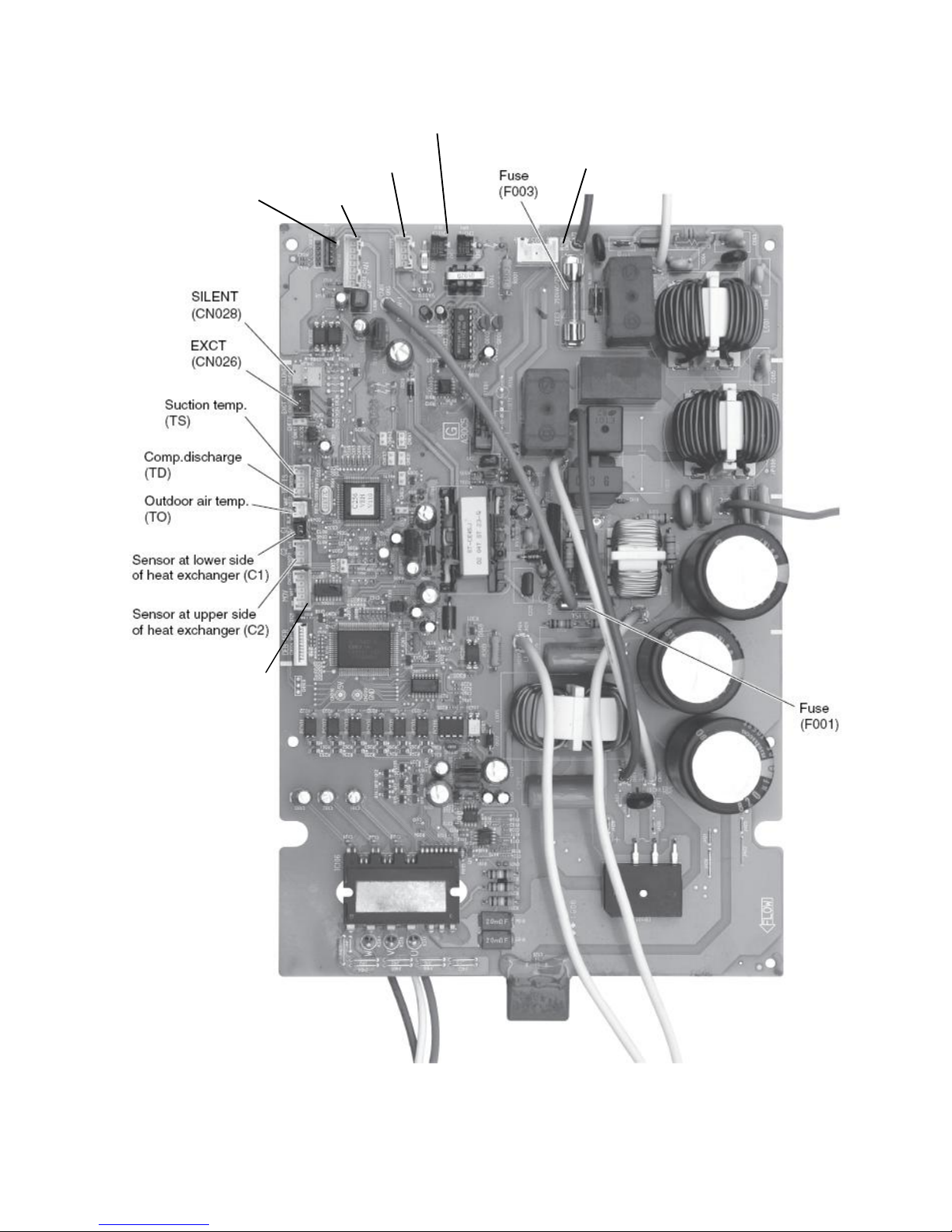
3.2.5 REFRIGERANT CIRCUIT POWER BOARD FOR UNITS 095 / 125
A3 board A056VH (up side) FOR UNIT 095
HIC temperature sensor plug
« Power » LED
EEPROM LED
Page 64

64
A3 board A056VH (bottom side) FOR UNIT 095
Expansion valve
(MOV)
Service Remocon
(RC-P)
Board ctrl signal (OC)
Board programming
PAC checker (ROM)
Fan
4 way valve (20S)
CHECK
Page 65

65
A3 board A086VH (up side) FOR UNIT 125
HIC temperature sensor plug
« Power » LED
EEPROM LED
Page 66
66
A3 board A086VH (bottom side) FOR UNIT 125
Expansion valve
(MOV)
4 way valve (20S)
Board ctrl signal (OC)
Board programming
PAC checker (CN012 ROM)
Fan
Service Remocon
(
RC-P)
Page 67

67
UNITS 095 / 125 – COMMENTS
• S002 rotary switch (10 positions, black) / S003 DIP switches (2P, blue):
Address for split air to air units – not used for the application.
The factory setting below must not be changed :
• CN041 Auto address plug (2P, white):
Normally, the addressing sequence between refrigerant circuit power board A3 and control board A2 takes place when power is
initially turned on at the factory.
In case of board replacement or problem of communication on the field, it can be necessary to launch again an addressing
sequence. For that, short circuit the pins of the plug.
During automatic address setting, LEDs 1 & 2 are blinking alternatively (open circuit these pins stops automatic address
setting).
After the power is turned ON, automatic address setting will not be functioned for over 1 minute and 30 seconds.
• CN042 Pump down plug (2P, white):
Used for split air to air units for refrigerant recovery sequence – not used for the application.
• CN032 RC-P Service remocon connection plug (5P, red): See PART 6
• JP007 jumper: Not used.
• S010 TERMINAL switch (black): Not used – Switch position “ON”.
• CN036 Test plug (2P): Used for PCB inspection in factory.
• CN031 MODE plug (2P): Not used.
• CN012 ROM plug (4P, white):
Used for PCB software loading in factory with “PAC checker” interface.
• CN026 EXCT plug (3P, red): Designed for capacity control – not used.
• CN028 SILENT (or QUIET) MODE plug :
Software version:
Unit Version Date
095 (2HP)
V110 Dec. 2011
125 (3HP)
V100 Jul. 2011
Page 68

68
3.2.6 REFRIGERANT CIRCUIT POWER BOARDS FOR UNITS 155 / 175 / 195
A3 board A116VH for units 155 / 175
A3 board A166VH for unit 195
Expansion valve
(MOV)
Service
Remocon
(RC-P CN032)
Board programming
PAC checker
(CN012 ROM)
4 way valve (20S) Fans ctrl
Fans supply
Board ctrl signal (OC)
« Power » LED
EEPROM LED
Page 69

69
UNITS 155 / 175 / 195 – COMMENTS
• S002 rotary switch (10 positions, black) / S003 DIP switches (2P, blue):
Address for split air to air units – not used for the application.
The factory setting below must not be changed :
• S001 AUTo ADDress push button switch (black):
Normally, the addressing sequence between refrigerant circuit power board A3 and control board A2 takes place when power is
initially turned on at the factory.
In case of board replacement or problem of communication on the field, it can be necessary to launch again an addressing
sequence. For that, press once the switch.
During automatic address setting, LEDs 1 & 2 are blinking alternatively (pressing again this switch stops automatic address
setting).
• S005 Pump down push button switch (red):
Used for split air to air units for refrigerant recovery sequence – not used for the application.
• CN032 RC-P Service remocon connection plug (5P, red): See PART 6
• JP007 jumper: Not used.
• CN036 Test plug (2P, red): Used for PCB inspection in factory.
• CN031 MODE plug (2P, white): Not used.
• CN012 ROM plug (4P, white):
Used for PCB software loading in factory with “PAC checker” interface.
• CN026 EXCT plug (3P, red): Designed for capacity control – not used.
• CN028 SILENT (or QUIET) MODE plug:
Software version:
Unit Version Date
155 (4HP)
V150 Sep. 2011
175 (5HP)
195 (6HP)
Page 70

70
HIC board for units 155 / 175 /195
Hybrid Integrated Circuit for inverter compressor
Diode bridge
HIC board
HIC temperature sensor plug
Page 71

71
3.2.7 A3 REFRIGERANT CIRCUIT POWER BOARD FOR UNITS 157 / 177 / 197
A3 board A166VH8
4 way valve (20S)
Power relay
Ctrl (MG-SW)
Fans ctrl
Expansion valve(MOV)
Fans
supply
Board programming
PAC checker (ROM)
Service Remocon
(RC-P CN032)
Board ctrl signal (OC)
« Power » LED
«Charge LED »
EEPROM LED
Page 72

72
UNITS 157 / 177 / 197 – COMMENTS
• S002 rotary switch (10 positions, black) / S003 DIP switches (2P, blue):
Address for split air to air units – not used for the application.
The factory setting below must not be changed :
• S001 AUTo ADDress push button switch (black):
Normally, the addressing sequence between refrigerant circuit power board A3 and control board A2 takes place when power is
initially turned on at the factory.
In case of board replacement or problem of communication on the field, it can be necessary to launch again an addressing
sequence. For that, press once the switch.
During automatic address setting, LEDs 1 & 2 are blinking alternatively (pressing again this switch stops automatic address
setting).
• S005 Pump down push button switch (red):
Used for split air to air units for refrigerant recovery sequence – not used for the application.
• CN032 RC-P Service remocon connection plug (5P, red): See PART 6
• JP007 jumper: Not used.
• CN036 Test plug (2P, red): Used for PCB inspection in factory.
• CN031 MODE plug (2P, white): Not used.
• CN012 ROM plug (4P, white):
Used for PCB software loading in factory with “PAC checker” interface.
• CN026 EXCT plug (3P, red): Designed for capacity control – not used.
• CN028 SILENT (or QUIET) MODE plug:
Software version:
Unit Version Date
157 (4HP)
V150
Nov. 2011
177 (5HP)
197 (6HP)
Page 73

73
HIC board for units 157 / 177 /197
Hybrid Integrated Circuit for inverter compressor
Diode bridge
HIC board
HIC temperature sensor plug
Page 74

74
3.2.8 REFRIGERANT CIRCUIT POWER BOARD FOR UNITS 257 / 307
A3 control board A246VH8
Service Remocon
(RC-P CN039)
Board programming
PAC checker
(
ROM
)
Board ctrl
signal (OC)
4 way valve (20S)
Expansion
valves
(MOV1-2)
Cranckcase heater
(20S)
Fan supply
Fan supply
Fan control
Fan control
Power relay
Ctrl (MG-SW)
« Power » LED
EEPROM LED
Page 75

75
UNITS 257 / 307 – COMMENTS
• S002 rotary switch (10 positions, black) / S003 DIP switches (2P, blue):
Address for split air to air units – not used for the application.
The factory setting below must not be changed :
• CN047 Auto address plug (2P, white):
Normally, the addressing sequence between refrigerant circuit power board A3 and control board A2 takes place when power is
initially turned on at the factory.
In case of board replacement or problem of communication on the field, it can be necessary to launch again an addressing
sequence. For that, short circuit the pins of the plug.
During automatic address setting, LEDs 1 & 2 are blinking alternatively (open circuit these pins stops automatic address
setting).
After the power is turned ON, automatic address setting will not be functioned for over 1 minute and 30 seconds.
• CN048 Pump down plug (2P, white):
Used for split air to air units for refrigerant recovery sequence – not used for the application.
• CN039 RC-P Service remocon connection plug (5P, red): See PART 6
• CN033 Test plug (2P, red): Used for PCB inspection in factory.
• CN038 MODE plug (2P, white): Not used.
• CN501 ROM plug (4P, white):
Used for PCB software loading in factory with “PAC checker” interface.
• CN030 EXCT plug (3P, red): Designed for capacity control – not used.
• CN037 SILENT (or QUIET) MODE plug:
Software version:
Unit Version Date
257 (8HP)
V110
Jan. 2012
307 (10HP)
Page 76

76
HIC board for units 257 / 307
Hybrid Integrated Circuit for inverter compressor
Diode bridge
HIC board
Page 77

77
A4 Supply and filter board for units 257 / 307
Page 78

78
3.2.9 ELECTRIC SUPPORT HEATER
Content Unit 095 125 155 157 175 177 195 197 257 307
Number of
elements
3 in parallel 3 – star coupling
Nominal voltage V 230V - on each heater element
Capacity kW 3 x 1.5 3 x 2 3 x 3
Body material Stainless steel 304L
Heating element
material
Stainless steel Incoloy 800
Heater
connected on
outlet of heat
exchanger
Safety thermostat
Manual
reset
Open if T > 115°C
Safety thermostat
Automatic
reset
Open if T > 80°C
Heat exchanger
Water pressure switch
Open if P< 0.6 bar
Page 79

79
PART 4 – INVERTER CONTROL
SPECIFIC FUNCTIONS
4.1 Heat pump water temperature control
4.2 Compressor frequency control
4.3 Max & Min frequency control
4.4 Current release control
4.5 Cooling high-load prevention control
4.6 Heat
ing high-load prevention control
4.7 Freeze prevention control in cooling mode
4.8 Discharge temperature control
4.9 Air heat exchanger defrost control
4.9.1 Flow chart of defrost control
4.9.2 Frost adherence detection
4.9.3 Heating mask time
4.9.4 Defrost cycle end
4.10 Fan control
4.11 Electronic expansion valve control
4.12 Water circulating pump control
4.13 Water flow monitoring
4.14 Heat pump base de-ice heater control
4.15 Heat pump outgoing water temperature alarm
4.16 Heat pump stand alone operation
4.17 Heat pump alarm signal for system control
Page 80

80
4.1 HEAT PUMP WATER TEMPERATURE CONTROL
Performed by A3 board
• The Inverter gestion is working or waiting in accordance with the ᇞT shown below.
ᇞT= TA – TY
T
A
: Water temperature from the installation – read by sensor TW1.
T
Y
: Resulting water temperature Setpoint Y
Note 1
: 10-minute mask time of the Inverter Gestion from WORKING to WAITING to avoid cycling.
Note 2
: 3-minute mask time of the Inverter Gestion from WAITING to WORKING to avoid cycling.
• By the control method the frequency of the compressor’s inverter is controlled in accordance with
the
ᇞT and the return water temperature from the installation.
Inverter frequency is controlled as follows
:
When
ᇞT is high (not yet reached the Controlled so that the inverter frequency is increased.
water temperature setpoint).
When
ᇞT is low Controlled so that the inverter frequency is decreased or kept.
(approximately +1.0 or less in the cooling mode or
approximately -1.0 or more in the heating mode).
When the return water temperature is Controlled so that the inverter frequency is increased.
rising in the cooling mode and
dropping in the heating mode.
When the return water temperature is Controlled so that the inverter frequency is decreased.
dropping in the cooling mode and
rising in the heating mode.
Note: The fluctuations of the compressor inverter frequency adjustments are calculated taking into account not only ᇞT, but
also-fluctuations in TA.
Page 81

81
4.2 COMPRESSOR FREQUENCY CONTROL
Performed by A3 board
The frequency of the compressor's inverter is limited by either of the following controls
depending on whether the cooling or heating mode is in operation.
• Cooling Mode : · Water Inlet temperature control
· Maximum and minimum frequency control
· Current release control
· Cooling high-load prevention control
· Cooling freeze prevention control
· Discharge temperature control
• Heating Mode : · Water Inlet temperature control
· Maximum and minimum frequency control
· Current release control
· Heating high-load prevention control
· Discharge temperature control
4.3 MIN. & MAX. FREQUENCY CONTROL
Performed by A3 board
The compressor's inverter frequency is controlled in accordance with the model and operation mode.
The maximum and minimum frequencies for each model are shown in the table below.
Note: There are cases in which frequency is limited with other control functions depending on operational conditions,
so operations are not always carried out in accordance with the maximum frequencies listed below.
Cooling Mode Heating Mode
Minimum Hz * Maximum Hz Minimum Hz * Maximum Hz
PHRIE 095
15~24 Hz 87 Hz 15~24 Hz 108 Hz
PHRIE 125
24 Hz 111 Hz 24 Hz 114 Hz
PHRIE 155
15~24 Hz 54 Hz 18~24 Hz 72 Hz
PHRIE 157
15~24 Hz 54 Hz 18~24 Hz 72 Hz
PHRIE 175
15~24 Hz 69.6 Hz 18~24 Hz 85 Hz
PHRIE 177
15~24 Hz 68.4 Hz 18~24 Hz 78 Hz
PHRIE 195
15~24 Hz 75 Hz 18~24 Hz 88 Hz
PHRIE 197
15~24 Hz 80.4 Hz 18~24 Hz 85 Hz
PHRIE 257
25~33 Hz 91.2 Hz 25~33 Hz 96 Hz
PHRIE 307
25~33 Hz 80 Hz 25~33 Hz 85 Hz
*There are cases in which the minimum frequency can vary to protect the compressor in accordance with outdoor air
temperature and thermal loads.
Page 82

82
4.4 CURRENT RELEASE CONTROL
Performed by A3 board
The inverter frequency is controlled so that the current value for the inverter compressor is less than the value listed
in the table below.
This current release control is required in order to prevent abnormal temperature increases in the inverter circuit
located within the electrical box and avoid HIC board damages.
The limited values of the primary current are modified in accordance with outdoor air temperature (T
O
).
Is (A)
Cooling Mode Heating Mode
PHRIE 095
10.2 A 12 A
PHRIE 125
16.5 A 18 A
PHRIE 155
20 A 21 A
PHRIE 157
7 A 8 A
PHRIE 175
23 A 23.5 A
PHRIE 177
10 A 11 A
PHRIE 195
27 A 27.5 A
PHRIE 197
13 A 14 A
PHRIE 257
13 A 13 A
PHRIE 307
15 A 15 A
Note
: The limited values are lowered when the outdoor air temperature is higher than 40°C in the cooling mode and
higher than 14°C in the heating mode.
4.5 COOLING HIGH-LOAD CONTROL
Performed by A3 board
This control is performed to limit the inverter frequency in order to restrict abnormal increases in pressure and highload operations in the cooling mode.
In accordance with the temperature of the outdoor heat exchanger temperature sensors (C1, C2), such controls are
performed as decreasing the inverter frequency and restricting its increase, etc.
If the temperature max (C1, C2) exceeds 64°C, operations are halted and then restarted 3 minutes later. If this
start/stop activity is repeated 10 times consecutively, alarm "P20" (cooling high-load error) occurs.
Type 95 125 155 157 175 177 195 197 257 307
a 64 64 61 61 61 61 61 61 64 64
b 61 59 55 57 55 57 55 57 55 53
c 59 57 53 55 53 55 53 55 54 52
d 58 56 51 53 51 53 51 53 52 50
e 53 53 49 51 49 51 49 51 48 47
Page 83

83
4.6 HEATING HIGH-LOAD CONTROL
Performed by A3 board
This system controls the inverter frequency when the high pressure's abnormal increase and high-load operating
prevention occur in the heating mode.
In accordance with the temperature of the water heat exchanger temperatures sensor (E1, E2), such controls are
performed as to limiting the increase of inverter frequency, decreasing it or halting operation of the compressor.
When the maximum temperatures (E1, E2) exceeds 64°C, the operation is halted and restarted after 3 minutes.
type 95 125 155 157 175 177 195 197 257 307
a
64 64 63 63 63 63 63 63 63 63
b
58 58 58 58 58 58 58 58 58 58
c
54 54 55 55 55 55 55 55 55 55
4.7 FREEZE PREVENTION CONTROL IN COOLING MODE
Performed by A3 board
The following control is performed during cooling operations, in accordance with the lowest water heat exchanger
temperatures (E1 or E2). (See the chart below.)
(1) If the temperature remains in the "J" zone (decreasing operation frequency) for 6 minutes, the operating
frequency of the compressor is decreased.
The operation frequency is amended every 30 seconds as long as the temperature is in this zone.
(2) If the temperature is in the "K" zone (operating frequency increase prevention zone), the operating frequency
of the compressor is maintained.
(3) If the temperature is in the "H" zone (operating frequency restriction zone) and the outdoor air temperature is
less than 32°C, the maximum operating frequency of the compressor is limited.
(4) If the temperature is in the "I" zone (normal operation zone), normal operations are performed.
(5) If the temperature is continuously in the "J" zone with the compressor's operating frequency reaches "0",
then temperature A, which is temperature for changing from the "J" zone to the "H" zone, is raised from 5°C
to 8°C, and operation continues until the temperature enters the "H" zone.
Page 84

84
4.8 DISCHARGE TEMPERATURE CONTROL
Performed by A3 board
The following control is performed to prevent the discharge temperature from rising abnormally in order to protect
the inverter compressor. In accordance with the temperature of the discharge sensor TD, such controls are
performed as to limiting the increase of inverter frequency, decreasing it or halting operation of the compressor.
* If the discharge temperature exceeds 111°C (or 115°C for 257 & 307 units), operations of the compressor are
halted and then restarted 3 minutes later.
If this start/stop activity is repeated 4 times consecutively, the alarm "P03" (abnormal discharge temperature)
occurs.
Page 85

85
4.9 AIR HEAT EXCHANGER DEFROST CONTROL
Performed by A3 board
4.9.1 FLOWCHART OF DEFROST CONTROL (1) (2) (3)
Page 86

86
4.9.2 FROST ADHERENCE DETECTION (1)
If the following conditions are satisfied during heating operations, it is regarded as "frost adherence is detected".
• Frost adherence detection is performed in accordance with the outdoor air temperature (TO) and the outdoor
heat exchanger temperature sensor (C1).
Note
: Frost adherence detection is not performed for the first 15-minute of compressor operations in the normal
heating mode.
• Frost adherence detection conditions
(a) With the outdoor air temperature (TO) being -13°C or above, the frost adherence condition shown
below are satisfied for whether 3 consecutive minutes or a total of 60 intermittent minutes, or the
outdoor heat exchanger temperature sensor (C1) remains -18°C or below for 20 consecutive
seconds.
(b) With the outdoor air temperature (TO) being less than -13°C, the outdoor heat exchanger
temperature sensor:
(C1) ≤ [(TO) – 5°C] for 20 consecutive seconds → Defrosting condition
(c) With the outdoor heat exchanger temperature sensor (C1) being less than -3°C, a total of 90 minutes
has elapsed (defrosting carried out periodically in accordance with the time).
4.9.3 HEATING MASK TIME (2)
This refers to the shortest time that heating operations must be performed without defrosting operations being
executed.
The mask time for this model is 25 minutes.
Note
: Defrosting operations will not be commenced until the defrosting mask time has elapsed, even if frost
adherence has been detected.
4.9.4 DEFROST CYCLE END (3)
Defrosting operations are ended when the following conditions are aligned:
(a) When the temperature of the outdoor heat exchanger temperature sensor (C1) is 12 or higher.
(b) When the temperature of the outdoor heat exchanger temperature sensor (C1) is 7 or higher for
60 consecutive seconds.
(c) When defrosting has been initiated for 10 minutes.
Page 87

87
4.10 FAN CONTROL
Performed by A3 board
• Cooling Mode:
The appropriate rotations per minute for the fan are determined in accordance with the outdoor air
temperature and the frequency of the compressor inverter.
The fan step is controlled between a range of W1 (Step 1) and WF (Step 16).
• Heating Mode:
The appropriate rotations per minute for the fan are determined in accordance with the outdoor air
temperature and the frequency of the compressor inverter.
The fan step is controlled between a range of W1 (Step 1) and WF (Step 16).
Note
: However, the fan is halted (Step 0) when defrosting is being carried out.
4.11 ELECTRONIC EXPANSION VALVE CONTROL
Performed by A3 board
The electrical expansion valve controls the amount of refrigerant that is allowed to flow in accordance with the
operation status.
The valve is adjusted in accordance with the discharge temperature (TD), the outdoor heat exchanger
temperature sensor (C1), the suction temperature sensor (TS), and the heat exchanger temperature sensors (E1
and E2).
• Cooling Mode:
Controlled so that the suction temperature (TS) - water heat exchange temperature minimum (E1 and E2)
is between 1°C and 5°C under normal conditions.
There are cases where the aperture opens wider than usual if the discharge temperature increases.
• Heating Mode:
Controlled so that the Suction Temperature (TS) - Outdoor heat exchange temperature (C1) is between
1°C and 5°C under normal conditions.
There are
4.12 WATER CIRCULATING PUMP CONTROL
Performed by A2 board -
see presentation § 3.2.4
In normal operation, water pump is actuated automatically by system control
(see details in the corresponding technical manual) :
-in heating mode when outdoor temperature is lower than the “non heating threshold”,
-during “Domestic Hot Water” cycle,
-in cooling mode (as soon as it is selected).
Anyway, it is possible to operate the circulating pump in a forced way; then water pump runs permanently. This
kind of operation can be needed for commissioning or maintenance (or operation without system control).
Forced circulating water pump operation:
- Make sure that the hydraulic circuit is ready (no leakage, pressure, valves open…).
- Press during 5 seconds the “RESET” button of the CWC2 control board.
The circulating pump starts (if it was stopped). This action has the priority to any control signal from the system.
The circulating pump indicator light “PP” flashes.
Page 88

88
- Check that the “W” water flow rate indicator light is on.
Other functions:
• Time delay: Water pump stop is time delayed (3 mn), but immediate in the case forcing is stopped.
• Anti-sticking: automatic operation for 5 seconds every 24 hours.
• Anti-freeze": function activated by setting micro-switch sW1-1 to "on" (delivery default setting). The pump
is started if outside temperature is below 0°C.
4.13 WATER FLOW MONITORING
Performed by A2 board -
see presentation § 3.2.4
When the circulating pump is in operation, a lack of water flow longer than 10 seconds will cause the heat pump to
stop.
The alarm light "AL" flashes.
If the lack of water flow continues for more than one minute (or if it happens more than 3 in the last hour), the water
flow fault is stored in A2 memory:
- The alarm light "AL" then remains on steady; the "W" water flow light flashes (once a second).
- The flow alarm has to be sent to the system, for that, the micro-switch sW1-2 must be set to "on".
- On A2 boards version 00 the circulating pump stops. On A2 boards versions 01 & 02, the water circulating
pump remains operating.
The alarm is reset by pressing the "reset" button, or turning the system "OFF", or by disconnecting the power.
4.14 HEAT PUMP BASE DE-ICE HEATER CONTROL
Performed by A2 board - see presentation § 3.2.4
The heater is actuated for a period of 30 mn if heat pump is in defrost and outdoor temperature
(measured by heat pump sensor “OT”) is lower than 0°C.
4.15 HEAT PUMP OUTGOING WATER TEMPERATURE ALARM
Performed by A2 board -
see presentation § 3.2.4
Note: this function is available only on A2 board in version 02.
See installation manual 1011597 concerning additional water outlet temperature sensor kit.
This alarm is detected by the TW2 sensor at the heat pump exchanger water outlet.
It is generated and stops the heat pump if the heat pump exchanger outgoing water temperature goes below a
threshold in the following cases:
- In heat mode, during defrost exclusively, if the temperature is below 16°C.
- In cool mode if the temperature is below 4°C.
This alarm is reset automatically (with a re-set differential on the threshold of + 4 K) for the first 3 events occurred the
previous hour. The "W" light of the CWC2 board flashes according to a specific rate (twice a second) to signal this
alarm. The "AL" light of the CWC2 board also flashes to signal this heat pump alarm in "automatic" phase.
If a 4th event occurs within the hour, the alarm is saved and goes to manual reset. The "AL" light of the CWC2
board remains steady to signal this heat pump alarm in "manual" phase. The alarm saved is transmitted to the
system for "GR" display. To help in troubleshooting this alarm, the "W" light continues to flash according to the
specific rate until the alarm is reset. The alarm report contact of the CWC2 board is activated.
On alarm reset, the "W" light resumes the state of the water flow input.
TW2 sensor fault:
This fault is managed like another fault on the heat pump giving rise to a "GR" system alarm.
When a sensor fault is detected, the heat pump stops and the "AL" light of the CWC2 board flashes during the
automatic reset phase. The "W" light of the CWC2 board flashes very quickly (flickers) to signal this alarm.
If the sensor fault persists, the alarm is saved after 30 minutes and goes into manual reset. The "AL" light of the
CWC2 board remains steady to signal this heat pump alarm in "manual" phase. The alarm saved is transmitted to
the system for "GR" display. To help in troubleshooting this alarm, the "W" light continues to flicker until the
alarm is reset.
On alarm reset, the "W" light resumes the state of the water flow input.
Page 89

89
4.16 HEAT PUMP STAND ALONE OPERATION
Performed by A2 board -
see presentation § 3.2.4
For the maintenance and commissioning operations, the heat pump can be operated in a “stand-alone”
configuration, without system control, using the specific maintenance remocon (see PART 6) and/or external
voltage free contacts.
The system can be disconnected in two ways:
- Either, with power off, disconnect the system communication line "BUS" from A2 board (connector “SC”).
- Or, by the system control unit, deactivate heat pump control by setting parameter 76 to "0" – see System
control manual.
To operate the heat pump, force the circulating pump (see § 4.12) before initiate an order via the specific
maintenance remote control or the external contacts.
Heat pump control with voltage free external contacts:
Inputs for external contacts are available on A2 (CWC2) board in order to force heat pump operation
(ON / OFF - Heat / cool). These inputs have priority
to the control signals initiated by means of the possible
maintenance remote control.
The state of these inputs is indicated by the lights placed on the board. Set points (heat and cool) must be adjusted
by
the maintenance remote control but for operation and control by contacts, maintenance remote control is not
mandatory.
ON/OFF:
-Closing a contact between “C” and “1” on the terminals block “ON/OFF” makes the unit starts.
Corresponding LED is lighted in green.
-Closing a contact between “C” and “0” on the terminals block “ON/OFF” makes the unit stops.
Corresponding LED is lighted in red.
In case of closing both contacts at the same time, priority is given to “OFF”.
Note: on A2 board in versions 01 & 02, “OFF” input is also active with system control connected.
HEAT / COOL:
-Closing a contact between “C” and “1” on the terminals block “HEAT/COOL” selects “HEAT” mode.
Corresponding LED is lighted in red.
-Closing a contact between “C” and “0” on the terminals block “HEAT/COOL” selects “COOL” mode. Corresponding
LED is lighted in green.
In case of closing both contacts at the same time, priority is given to “HEAT”.
Note: on A2 board in versions 01 & 02, “HEAT” input is also active with system control connected.
A voltage free change-over contact (use in 24 V max.) is available on A2 (CWC2) board for remote heat pump alarm
signaling.
4.17 HEAT PUMP ALARM SIGNAL FOR SYSTEM CONTROL
Performed by A2 board - see presentation § 3.2.4
Heat pump faults coming from the frigorific circuit are classified in 2 categories:
- Manual reset faults:
Memorized by board A2 as soon as they appear and transmitted to the system control. The A2 board alarm light
“AL” comes on steady.
- automatic reset faults:
The A2 board alarm light “AL” flashes as soon as a fault appear. If it lasts longer than 30 minutes, fault is memorized in
board A2 and transmitted to the system control. The alarm light “AL” then remains steady.
The detailed list of faults is indicated in part 5.
To determine the exact nature of the fault, refer to LED1 & LED2 on the power board A3 or connect the specific
maintenance remocon to the heat pump (see Part 6).
Page 90

90
PART 5 – SERVICE PROCEDURES
5.1 Frigorific circuit alarms
5.1.1 List of alarms
5.1.2 Alarm messages display
5.1.3 Alarms reset
5.1.4 Symptoms & parts to inspect
5.1.5 Alarms diagnosis
5.1.6 HIC board checking
5.1.7 Diode bridge checking
5.2 Hydraulic circuit alarms
5.2.1 List of alarms
5.2.2 Alarms reset
5.2.3 Symptoms & parts to inspect
5.2.4 A2 board checking
5.3 System control alarms
5.3.1 List of alarms
5.3.2 Alarms reset
5.3.3 A1 board checking
5.4 Boards replacement
5.4.1 A2 board
5.4.2 A3 board
5.4.3 A4 board
5.4.4 HIC board
5.5 Sensors characteristics
5.5.1 Heat pump control sensors
5.5.2 System control sensors
WARNING:
Before carrying out any work on the machine, make sure that its power supply is switched off and the access to it
is prevented. Any work must be carried out by personnel qualified and authorized to work on this type of machine.
Page 91

91
5-1 FRIGORIFIC CIRCUIT ALARMS
Managed by A3 board and partially by A2 board.
5.1.1 LIST OF ALARMS
Type Designation Code Action Reset(*)
Serial
communication
errors
&
Mis-setting
Maintenance
remocon detects
error signal from
A2 board
-Poor reception of the signal on the maintenance remocon
-Auto address not completed
E01 stop
Automatic
(then manual)
-Poor transmission of the signal on the maintenance
remocon
E02 stop
Automatic
(then manual)
A2 board detects
error signal from
remocon
-Poor reception of the signal on A2 board from the
maintenance remocon
E03 stop
Automatic
(then manual)
A2 board detects
error from A3
board
-Poor reception of the signal on A2 board from the A3
board
E04 stop
Automatic
(then manual)
-Poor transmission of the signal from A2 board to the A3
board
E05 stop
Automatic
(then manual)
A3 board detects
error from A2
board
-Poor reception of the signal on A3 board from the A2
board
E06 stop
Automatic
(then manual)
-Poor transmission of the signal from A3 board to A2 board E07 stop
Automatic
(then manual)
Automatic address
setting failed
-Incorrect capacity set in A2 board detected. Too low. E15 stop manual
-Incorrect capacity set in A2 board detected. Too high. E16 stop manual
-A2 board not detected during automatic address
sequence
E20 stop manual
Mis-wiring
-Mis-wiring between boards
-Missing phase on power supply
E22 stop manual
Communication
trouble
-Communication abnormal (A3 board). E31 stop
Automatic
(then manual)
Sensor failure
Sensor circuit
open or short
circuit /
Sensor failure
-Abnormal sensor for the inlet temp. on the H/E – “liquid
line” in cooling - (E1/S7)
F01 stop
Automatic
(then manual)
-Abnormal pressure sensor (E2P/B1) on the H/E
-Loss of refrigerant charge
F02 stop
Automatic
(then manual)
-Abnormal sensor for the compressor discharge
temperature (TD/S5)
F04 stop
Automatic
(then manual)
-Abnormal sensor for the air heat exchanger temp. (C1/S2) F06 stop
Automatic
(then manual)
-Abnormal sensor for the air heat exchanger temp. (C2/S1) F07 stop
Automatic
(then manual)
-Abnormal sensor for outdoor temp. (TO/S4) F08 stop
Automatic
(then manual)
-Abnormal sensor for water inlet temp. (TW1/S8) F10 stop
Automatic
(then manual)
-Abnormal sensor for compressor suction temp. (TS/S3) F12 stop
Automatic
(then manual)
Component
failure
EEPROM
-Abnormal non-volatile memory (EEPROM) on A2 board. F29 stop manual
-Abnormal non-volatile memory (EEPROM) on A3 board F31 stop manual
Mis-setting Setting error
-Unit type mismatch between A3 and A2 (parameter) L02 stop manual
-No address setting on A2 board L08 stop manual
-No unit capacity setting on A2 board L09 stop manual
-Incorrect capacity setting on A3 board L10 stop manual
-incorrect unit type setting on A2 board L13 stop manual
Activation of
protective
device
A3 board
-High discharge temperature of compressor P03 stop manual
-High refrigerant pressure switch activated
(for 257 & 307 units only)
P04 stop manual
-Low current on power supply
(missing phase or incorrect phases order)
P05 stop manual
-No refrigerant P15 stop manual
-Four way valve locked P19 stop manual
-High refrigerant pressure P20 stop manual
-Fan(s) trouble P22 stop manual
-Incorrect current value for compressor (over current on
HIC PCB)
P26 stop manual
-Incorrect current value for compressor (trouble on motor
detection circuit - MDC)
P29 stop manual
-Incorrect current value for compressor (overload) H01 stop manual
(*) see § 5.1.3
Page 92

92
5.1.2 ALARM MESSAGES DISPLAY
2 ways for reading alarm messages:
-with maintenance remocon connected to A2 board (connector RC). Alarm code is directly displayed.
See details PART 6.
-with LED 1 & LED 2 on A3 board.
LED 1 & LED 2 display:
Page 93

93
Alarm Code is composed of two parts. First part is a letter, second part is a number:
The blinking of LED 1 indicates the code letter The blinking of LED 2 indicates the number
LED 1 LED 2
Number of Blinks Alarm Code Letter Number of Blinks Alarm Code Number
0 No alarm 0 No alarm
2 P 1 1
3 H 2 2
4 E …. ….
5 F 16 16
6 L
17 17
Examples: (other than E15, E16 and E20)
Alarm code LED 1 alternately LED 2
P04 Blinks twice = P Blinks four times = 04
-
H01 Blinks three times = H Blinks once = 01
-
E03 Blinks four times = E Blinks three times = 03
-
F07 Blinks five times = F Blinks seven times = 07
-
L09 Blinks six times = L Blinks nine times = 09
-
LED 1 & 2 – Other indications:
LED 1 LED 2 Remarks
Power ON sequence
Step 1 : no communication A3 / A2
Step 2 : communication received from A2
Step 3 : normal communication
On
Off
Off
On
On
Off
In normal operation
A3 EEPROM error (F31)
Pre trip (insufficient gas)
Pre-trip (P20 - HP)
Pre-trip (other)
On
Blinks (0.25/0.75)
Blinks (0.75/0.25)
Blinks (0.5/0.5)
Blinks (0.5/0.5)
Off
Off
Off
During auto address & initial
communication ; then F31 displayed.
P03
Alarms Blinks Blinks See details in table before
Insufficient refrigerant indicator Blinks (0.5/0.5) Off
Refrigerant recovery mode Blinks (0.5/0.5) On Not used – only for split heat pumps
Automatic address setting (A3 – A2)
Automatic address setting in progress
Automatic address setting alarm (E15)
Automatic address setting alarm (E20)
Automatic address setting (other than E15/E20)
Blinks (0.5/0.5)
Blinks (0.25/0.75)
Blinks (0.75/0.25)
Blinks (0.5/0.5)
Blinks (0.5/0.5)
Blinks (0.25/0.75)
Blinks (0.75/0.25)
Blinks (0.5/0.5)
Blinking alternately
Blinking simultaneously
Blinking simultaneously
Blinking simultaneously
Note: blinking (0.25/0.75) means that LED illuminates for 0.25 seconds and then is Off for 0.75 seconds.
Page 94

94
5.1.3 ALARMS RESET
Performed by A2 board
Heat pump faults coming from the frigorific circuit are classified in 2 categories:
- “Manual” reset faults:
Memorized by board A2 as soon as they appear and transmitted to the system control.
The A2 board alarm light “AL” comes on steady.
Heat pump is stopped until alarm is reset.
- “Automatic” reset faults:
The A2 board alarm light “AL” flashes as soon as a fault appear. Heat pump is stopped.
If the default lasts less than 30 minutes, alarm is automatically cleared and heat pump starts again.
If it lasts longer than 30 minutes, default is memorized by board A2 and transmitted to the system control.
The alarm light “AL” then comes on steady.
Heat pump is stopped until alarm is reset.
How to reset the alarm:
Note : problem must be solved before final reset action.
Alarm reset by pressing push button « RESET » on A2
board for 5 seconds
Alarm reset by setting the system control in OFF position
See detail in corresponding technical manual
Alarm reset by switching off power supply
This action is recommended in case of problem of
setting error (E15, E16, E20, L02, L08, L09, L10, L13)
and memory (F29, F31).
Page 95

95
5.1.4 SYMPTOMS & PARTS TO INSPECT
Serial communication errors & mis-setting
Maintenance
remocon
alarm
display
Alarm
contents
Judgement conditions
clearing
condition
Judgement and correction
E01
Maintenance
Remocon detected
error signal from
A2 board
Serial signal receiving failure
Automatic
recovery
1. Check remocon connection
2. Check address on A2 board
3. Check A2 board
E02
Serial signal sending failure
E03
A2 board detected
error signal from
remocon
Serial signal failure
Automatic
recovery
1. Check remocon connection
2. Check remocon configuration (see part 6)
3. Check address on A2 board
4. Check A2 board
E04
A2 board detected
error signal from
A3 board
Serial signal receiving failure
Automatic
recovery
1.Check connection between boards
(OC connector)
2. Check addresses – if necessary, launch
auto address sequence
3. Check boards
E05
Serial signal sending failure
E06
A3 board detected
error signal from
A2 board
Serial signal receiving failure
Automatic
recovery
Automatic
recovery
1. Check connection between boards
(OC connector)
2. Check A2 and A3 boards.
E07
Serial signal sending failure
E15
Automatic address
setting failure.
A2 capacity/number
parameters (too low)
Power supply
reset
recovery
1. Check A2 parameters (see Part 6) - if
necessary, launch auto address sequence
2. Check connection between boards (OC
connector)
3. Check A2 board
4. Check A3 board
E16
A2 capacity/number
parameters (too low)
E20
A3 board cannot receive any
serial signals from A2 board.
E22
Mis-wiring error
Mis-wiring between boards
or
Missing phase on power
supply
Power supply
reset
recovery
1. Check wiring.
2. Check power supply connections
E31
(*)
Communications
trouble within
boards
No communication possible
with MDC for 3 minutes or
longer
Automatic
recovery
Check A3 board
Refer to diagnosis method (section 5.1.5)
(*) see detail § 5.1.5
Page 96

96
Sensors failure
Maintenance
remocon
alarm
display
Alarm
contents
Judgement conditions
clearing
condition
Judgement and correction
F01
Disconnection, open
circuit or short
circuit
in H/E temp. sensor
“liquid line”
E1/S7
Open circuit or short circuit
Automatic
recovery
1. Check “liquid line” temp. sensor E1/S7
2. Check connection
3. Check A2 board
F02
Abnormal pressure
detected in the plate
exchanger
with
E2P/B1 pressure
sensor
Value delivered by
pressure sensor is out off
range
Automatic
recovery
1. Check pressure in the frigorific circuit
2. Check connection between E2P and A2
board
3. Check JTP bridge on A2 board, (set between
pins 2 & 3” = factory setting)
3. Check U voltage on E2P connector on A2
board, pins 1/3 (24V DC):
20V < U < 26V
Right voltage: E2P sensor damaged
Wrong voltage: A2 board damaged
F04
(*)
Disconnection, open
circuit or short
circuit
in discharge
temperature sensor
TD/S5
Sensor detection error
(90°C or more after
60 minutes has
elapsed since the
compressor was halted
- open circuit)
Automatic
recovery
1. Check discharge temp. sensor TD/S5
2. Check (A3) board
Refer to diagnosis method (section 5.1.5)
F06
(*)
Disconnection, open
circuit or short
circuit
in sensor C1/S2
Open circuit or short circuit
Automatic
recovery
1. Check Air heat exchanger temperature
sensor C1/S2
2. Check A3 board
Refer to diagnosis method (section 5.1.5)
F07
(*)
Disconnection, open
circuit or short
circuit
in outdoor unit heat
exchanger temp.
sensor C2/S1
Open circuit or short circuit
Automatic
recovery
1. Check Air heat exchanger temperature
sensor C2/S1
2. Check A3 board
Refer to diagnosis method (section 5.1.5)
F08
(*)
Disconnection, open
circuit or short
circuit
in sensor TO/S4
Open circuit or short circuit
Automatic
recovery
1. Check outdoor air temp. sensor TO/S4
2. Check (A3) board
Refer to diagnosis method (section 5.1.5)
F10
Disconnection, open
circuit or short
circuit
in water inlet temp.
sensor TW1/S8
Open circuit or short circuit
Automatic
recovery
1. Check water inlet temp. sensor TW1/S8
2. Check (A2/CWC2) board
F12
(*)
Disconnection, open
circuit or short
circuit
in suction temp.
sensor TS/S3
Open circuit or short circuit
Automatic
recovery
1. Check suction temp. sensor TS/S3
2. Check A3 board
Refer to diagnosis method (section 5.1.5)
F29
EEPROM trouble
on A2 board
Reading/writing failure
Power supply
reset recovery
1. Check EEPROM of A2 board
2. Check A2 board
F31
EEPROM trouble
on A3 board
Reading/writing failure
Power supply
reset recovery
1. Check EEPROM of A3 board
2. Check A3 board
(*) see detail § 5.1.5
Page 97

97
Mis-setting
Maintenance
remocon
alarm
display
Alarm
contents
Judgement conditions
clearing
condition
Judgement and correction
L02
A2 and A3 boards
settings are
incompatible
A2 board judged
incompatible
with A3 board
(wrong spare part or
wrong parameters setting)
Power reset
recovery
1. Check setting parameters in the EEPROM of A2
2. Check A2 board
3. Check setting parameters in the EEPROM of A3
L08
Settings failure
Incorrect address in
EEPROM of A2 board.
Power reset
recovery
Check address setting in the EEPROM of A2
board
L09
Settings failure
Incorrect capacity in
EEPROM of A2 board.
Power reset
recovery
Check capacity setting in the EEPROM of A2
board
L10
Settings failure
Capacity not set in
EEPROM of A3 board
Power reset
recovery
Check capacity setting in the EEPROM of A3
board
L13
Settings failure
A3 and A2 board types of
unit judged incompatible
(wrong spare part or
wrong parameters setting)
Automatic
recovery
1. Check setting parameters in the EEPROM of A2
2. Check A2 board
3. Check setting parameters in the EEPROM of A3
4. Check A3 board
Page 98

98
Activation of protective device
Maintenance
remocon
alarm
display
Alarm
contents
Judgement conditions
clearing
condition
Judgement and correction
P03
Abnormal discharge
temperature:
Discharge temp. detected
at or above specified
value
• Discharge temp. TD exceeds X°C
X = 111°C : For models
095/125/127/155/157/175/177/195/197
X = 115°C: for models 257/307
• Alarm after 4 consecutive pre-trips
Recovery
at restart
1. Check refrigerant circuit (leakage)
2. Check electronic expansion valve
3. Check discharge temperature sensor
TD/S5
P04
High refrigerant pressure
(switch)
Only for units 257/307
High refrigerant pressure switch activated
Threshold = 41.5 bars
Recovery
at restart
Check A3 control board
P05
• Missing phase or
incorrect phases order
(for three-phase models)
or AC power supply error
• Current Transformer
disconnected
•Current value transmitted to A3 board is
low or the phases are not in correct
order (for three-phase models)
When no AC power input for
more than 3 minutes: alarm after 5
consecutive pre-trips
Recovery
at restart
1.Check power supply and phases order
2.Check current transformer connection
3.Check HIC
4.Check A3 board
P15
Insufficient refrigerant
detected.
• Discharge temperature TD is 95°C or
higher (100°C for models 257/307)
• Electronic expansion valve is at Step
480 (Step 960 for models 257/307).
• The current value from the MDC
module is 2.0A or less (6A or less for
models 257/307).
When the above conditions has
continued for 1 minute
Recovery
at restart
1.Check refrigerant circuit (leakage)
2.Check electronic expansion valve
P19
4-way valve trouble:
Judged after 5 minutes
had elapsed since the
compressor was switched
on
•Water heat exchanger temperature
drops even though compressor is
switched on during the heating mode.
[min(E1,E2P)] is 10°C or lower.
•Water heat exchanger temperature rises
even though compressor is switched on
during cooling mode. E2P is
50°C or higher.
•Alarm after 2 consecutive pre-trips
Recovery
at restart
1. Check 4-way valve
2. Check 4-way valve wiring
3. Check position of sensors E1 & C1
4. Check A3 board
P20
High-pressure protection
error caused by cooling
high-load max (C1/S2,
C2/S1) temperature
• Air H/E temperature exceeds X°C
X = 64°C: for 095/125/257/307
X = 61°C: for 155/157/175/177/195/197
• Alarm after 10 consecutive pre-trips:
for 095/125/155/157/175/177/195/197
• Alarm after 4 consecutive pre-trips:
For 257/307
Recovery
at restart
1. Check cleanliness of air H/E
2. Check refrigerant amount
3. Check sensors C1/S2 and C2/S1
P22
(*)
Fan motor trouble:
fan inverter protection
circuit was activated, or
lock was detected on fan
motor
Inverter stops after fault is detected
Alarm after 4 consecutive pre-trips
Recovery
at restart
Fan motor over current protection circuit
is activated:
• Check A3 board
• Check fan
Refer to diagnosis method (section 5.1.5)
P26
(*)
Comp. inverter protection
circuit was activated.
Short-circuit on HIC
board
(Short time: 0.8 seconds
or less)
HIC temperature
protection
Inverter stops after fault is detected
Alarm after 4 consecutive pre-trips
Recovery
at restart
Temp.
dropped
1. Check HIC board
• Wiring trouble
• HIC failure
• Contact trouble – heat sink
2. Check compressor
Refer to diagnosis method (section 5.1.5)
P29
(*)
Error in current detection
circuit:
• AC current value is high,
even while compressor is
halted.
Inverter halted after fault detected
Alarm after 4 consecutive pre-trips
Recovery
at restart
1. Check HIC board (& diode bridge)
2. Check compressor
Refer to diagnosis method (section 5.1.5)
(*) see detail § 5.1.5
Page 99

99
Activation of protective device
Maintenance
remocon
alarm
display
Alarm
contents
Judgement conditions
clearing
condition
Judgement and correction
H01
Over-current error Inverter stops after fault is detected.
Recovery
at restart
1.Refrigerant cycle abnormal
overload operations
2.Screws connecting the HIC
circuit between the heat
sink (HIC radiator) are loose
3.Faulty cooling of heat sink (HIC)
4.Check A3 PCB wiring
A3 board power supply
Maintenance
remocon
alarm
display
Alarm
contents
Judgement conditions
clearing
condition
Judgement and correction
No
display!
“Power” LED off
Problem of power supply
on A3 board
Unit does not operate
No alarm displayed
Recovery
at restart
1.Check power supply on board
2.Check board wiring
3.Check fan(s)
4.Check expansion & 4 ways
valves
5.Check A3 board
Page 100

100
5.1.5 ALARM DIAGNOSIS: “E31”-“F04”-“F06”-“F07”-“F08”-“F12”-“P22”-“P26”-“P29”
For models 095/125/155/157/175/177/195/197:
 Loading...