

DOSSIER TECHNIQUE
F
TECHNICAL INSTRUCTIONS
DOSSIER TECNICO
MANUAL TÉCNICO
TECHNISCHE DOKUMENTATION
MW
UNITES TERMINALES MURALES
WALL TYPE TERMINAL UNITS
UNITÀ TERMINALI MURALI
UNIDADES TERMINALES TIPO MURAL
WANDGERÄTE-WASSERGEKÜHLT
GB
I
E
D
Froid Chaud
Cooling Heating
Freddo Caldo
Frio Calefaccion
Kalt Warm
MW 2 - 2 100 W - 2 700 W
MW 3 - 2 800 W - 3 500 W
MW 4 - 4 000 W - 5 100 W
MW 5 - 5 200 W - 6 500 W
Janvier 1996 10 12 088 - F.GB.I.E.D - 01

MARKING
GB
This product marked conforms to the essential requirements of the European Directives:
- Low voltage no. 73/23 EEC, modified 93/68 EEC,
- Electromagnetic Compatibility no. 89/336 EEC, modified 92/31 and 93/68 EEC.
CONTENTS
TECHNICAL INSTRUCTIONS
1 - Application - Use........................................................................................................2
2 - Description.................................................................................................................3
3 - Physical characteristics .............................................................................................4
4 - Performances.............................................................................................................4
5 - Control ....................................................................................................................... 6
6 - Accessories................................................................................................................6
INSTALLATION INSTRUCTIONS
1 - General ......................................................................................................................7
2 - Introduction ................................................................................................................7
3 - Installation..................................................................................................................7
4 - Connections.............................................................................................................10
5 - Starting.....................................................................................................................14
6 - Maintenance ............................................................................................................15
7 - Wiring diagram.........................................................................................................15
TECHNICAL INSTRUCTIONS
1 - APPLICATION - USE
• This equipment is intended for the air-conditioning of premises and to provide comfort for the personnel.
FUNCTIONS
• Cooling or heating by means of a 2-pipe water coil.
• Ventilation with filtration (built-in filter).
RANGE
• There are 4 models with different capacities in the MW range.
• The air handler is supplied with its room thermostat.
• A condensate drain pump system is a factory-fitted accessory.
APPLICATIONS
• This range of air handlers, stemming directly from the direct expansion range, is characterised, thanks to its wall-mounting
configuration, by:
- attractiveness,
- compactness (using unused spaces),
- a low sound level.
2

2 - DESCRIPTION
GB
MW 2
MW 3
1
6
1 - Air inlet (suction)
2 - Air outlet (blowing)
3 - Vertical deflection louvre control switch
4 - Motorised vertical deflection louvre
5 - Manual horizontal deflection louvre
6 - Air filters
1
6
MW 4
MW 5
2
2 45 3
4
35
Model
Tangential fan
Electric motor
with internal thermal protection
Power supply 230 V / 1 + T / 50 Hz
Number of speeds
Copper / Aluminium exchanger
Number of rows
Hydraulic connection Copper
Water capacity litres
Condensate drain pump (accessory)
Air filter (washable)
• Plastic body.
• P.E.R. piping.
PER
MW 2
●
●
●
3
●
2
10/12
10/12
0.9
●
●
MW 3
●
●
●
3
●
2
10/12
10/12
0.9
●
●
MW 4
●
●
●
3
●
2
14/16
13/16
1.2
●
●
MW 5
●
●
●
3
●
2
14/16
13/16
1.2
●
●
3

3 - PHYSICAL CHARACTERISTICS
GB
3.1 WEIGHT
Air handler
Net weight (kg)
MW 2
MW 3
MW 4
MW 5
3.2 DIMENSIONS
H
312
°C
20
71
15
25
30
117
Thickness : 27.5 mm
4 - PERFORMANCES
4.1 NOMINAL CONDITIONS
Model
Total cooling capacity LS kW
(1) MS kW
Sensible cooling capacity LS kW
(1) MS kW
10
10
13.5
13.5
HS kW
HS kW
Packed weight (kg)
13
13
17.7
17.7
LP
MW 2
MW 3
MW 4
MW 5
MW 2
1.4
1.5
2.1
1.3
1.5
1.5
MW 3
2.4
2.6
2.8
1.7
1.9
2.1
MW 4
3.3
3.7
4
2.3
2.7
2.9
L
810
810
1000
1000
MW 5
4.6
4.9
5.2
3.2
3.5
3.8
H
360
360
360
360
P
180
180
205
205
Pressure drop on water in cooling mode kPa
(1) (10 kPa = 1 m W.G.)
Heating capacity LS kW
(2) MS kW
HS kW
Pressure drop on water in heating mode kPa
(2) (10 kPa = 1 m W.G.)
Air flow rate LS m
MS m
HS m
3
3
3
/h
/h
/h
3
2.2
2.4
2.7
2.4
325
370
430
5
2.9
3.2
3.5
4.1
325
370
430
Characteristics of fan motor
230 V / 1/ 50 Hz (3) W
(4) A
Maximum power input W
28
0.13
54
28
0.13
54
(with condensate pump)
Maximum current A
Sound power level LS dB(A)
(5) MS dB(A)
HS dB(A)
Sound pressure level (at 2.5 m indoors) LS dB(A)
(5) MS dB(A)
HS dB(A)
0.25
40
45
49
22
27
31
0.25
40
45
49
22
27
31
(1) Air inlet: 27°C (DB) / 19°C (WB) ; water: inlet at 7°C at high speed, outlet at 12°C
(2) Air inlet: 20°C; water inlet: 50°C (same flow-rate as under other conditions(1)).
(3) Max. power consumption (at high speed).
(4) Max. current consumption (at high speed).
(5) Without condensate pump accessory.
11
3.8
4.5
5.1
9
495
630
760
13.8
665
760
855
72
0.30
98
0.39
112
0.45
46
51
54
28
33
36
Note :
Maximum water inlet
temperature: 60°C
17
5.5
6
6.5
86
0.5
54
57
58
36
39
40
4

4.2 COOLING PERFORMANCES
AIR INLET 24°C, 50% RH
Model
MW 2
MW 3
MW 4
MW 5
Fan speed
LS
MS
HS
LS
MS
HS
LS
MS
HS
LS
MS
HS
P tot
0.9
0.9
1
1.2
1.2
1.3
1.9
2
2.2
2.6
2.7
2.9
AIR INLET 27°C, 47% RH
Model
MW 2
MW 3
MW 4
MW 5
Fan speed
LS
MS
HS
LS
MS
HS
LS
MS
HS
LS
MS
HS
P tot P sens Dve Pdc
1.1
1.2
1.3
2
2.1
2.2
2.7
3
3.2
3.8
3.9
4.1
7/14°C 7/12°C
P sens Dve Pdc
0.9
0.9
1
1.2
1.2
1.3
1.7
2
2.2
2.3
2.5
2.9
7/14°C 7/12°C
1.1
1.2
1.3
1.5
1.7
1.8
2.1
2.4
2.7
2.9
3.1
3.3
Water temperatures (*)
P tot P sens Dve Pdc
1
125
162
274
351
155
275
392
502
0.5
1
2
3
Water temperatures (*)
1
2
4
6
1.1
1.1
1.5
1.9
2
2.4
2.7
2.9
3.3
3.5
3.7
P tot
1.4
1.5
2.1
2.4
2.6
2.8
3.3
3.7
4
4.6
4.9
5.2
1
1.1
1.1
1.5
1.9
2.4
2.7
2.9
3.3
3.5
3.7
P sens Dve Pdc
1.3
1.5
1.5
1.7
1.9
2.1
2.3
2.7
2.9
3.2
3.5
3.8
196
345
2
496
634
356
486
695
887
1
3
6
10
3
5
11
17
GB
P tot : Total cooling capacity in kW
P sens : Sensible cooling capacity in kW
(*) Calculated with the high fan speed, water flow constant for the 3 speeds.
Dve : Water flow rate in litres/hour
Pdc : Pressure drop on water in kPa (1 m W.G. = 10 kPa)
4.3 HEATING PERFORMANCES
Water inlet
Model
MW 2
MW 3
MW 4
MW 5
P tot : Total cooling capacity in kW.
Dve : Water flow rate in litres/hour (corresponding to nominal conditions - § 4.1).
Pdc : Pressure drop on water in kPa (1 m W.G. = 10 kPa).
Fan speed
P tot Dve Pdc
LS
MS
HS
LS
MS
HS
LS
MS
HS
LS
MS
HS
50°C 35°C
2.2
2.4
2.7
2.9
3.2
3.5
3.8
4.5
5.1
5.5
6
6.5
356
486
695
887
2.4
4.1
9
13.8
P tot
1.1
1.2
1.3
1.4
1.6
1.8
1.9
2.2
2.5
2.7
3
3.2
Dve Pdc
356
486
695
887
2.6
4.4
9.7
14.8
5

5 - CONTROL
GB
• Control by "On/Off" action on ventilation. (Operation of the on-off valve, not supplied, is possible).
• Provided by an electronic room thermostat supplied with each air handler (connection not included).
CHARACTERISTICS OF THE ROOM THERMOSTAT
Supply voltage : 230 VAC
Control differential : 0.4 K ± 0.1 K
Operating temperature : 0 / 40°C
Protection class : Cl. II
Interference immunity : Level 4 CEI 801-2 and 801-4
• It is possible to invert the direction of action of the room
thermostat (cooling or heating) by connecting an external
contact (not included), for example, from the hydraulic
module (MH).
The same contact can control several room thermostats
provided the length of the control wire to each room thermostat does not exceed 150 m.
• Available as an accessory: Remote temperature probe.
3-position
speed selector
switch
On/Off
switch
3
2
1
°C
20
15
25
30
Indicator light Temperature setting
knob
(15 to 30°C)
6 - ACCESSORIES
6-1 CONDENSATE DRAINAGE SYSTEM
• Factory-fitted accessory.
• Oscillating piston electromagnetic type pump with float
detection unit controlling the 3 levels of operation (On/Off/
Safety).
• If the water is not discharged correctly, a safety device
prevents the fan from operating.
CAUTION: This device requires regular specific maintenance.
6.2 REMOTE TEMPERATURE PROBE
for room thermostat
• Enables the control thermostat to be put outside the premises to be air-conditioned.
• This temperature probe (CTN type - 33 ký) comes in an attractive, unobtrusive, wallmounted plastic case (protection class IP30).
Discharge
height in m
(W G) *
*Under nominal operating conditions (at high speed).
MW 2 MW 3 MW 4 MW 5
5543
6

INSTALLATION INSTRUCTIONS
°C
20
15
25
30
1
2
3
1 - GENERAL
• The equipment must be installed, started-up and maintained by authorised and qualified personnel, in accordance with local
rules and professional standards.
1.1 GENERAL SUPPLY CONDITIONS
• Generally speaking, the material is transported at the consignee's risk.
• The consignee must immediately provide the carrier with written reserves if he finds any damage caused during transport.
1.2 VOLTAGE
• Before any operation, check that the voltage and the frequency indicated on the device corresponds with that of the mains.
2 - DESCRIPTION
• See § 2 above of the Technical Manual.
ACCESSORIES SUPPLIED WITH THE UNIT
Accessory Q
1 - Support plate
ty
Wall support for the internal
1
Use
unit.
Accessory Q
5 - Large screws 12
ty
Use
For fixing the support plate
with the plugs and the remote
control.
GB
2 - Instructions 2 • Installation instructions.
• Operating instructions.
3 - Plugs 10
For fixing the support plate
and remote control.
4 - Hydraulic
adaptors
Adaptors for connection with
2 + 2
copper or PER pipes
3 - INSTALLATION
3.1 CHOOSING THE LOCATION
Select the location for the unit on the basis of the following
criteria:
• The device is intended for installation in sheltered premises.
Do not install in very damp places or exposed to projections of water (e.g., laundry rooms).
• Do not install next to electric connections.
• The air intake and blowing grilles must be free from any
obstacle so that blowing can occur correctly in the whole
room.
• The wall on which the air handler will be fixed must be
sufficiently thick for there not to be any resonance and so
as not to produce any noise.
• Provide for the pipes and electric cables.
• It is essential to leave the clear space around the unit (see
drawing opposite).
16 - Room
Regulation and control
thermostat
7- Trim 1 Finger plate for the hole in
the wall.
8 - Filters
Spare parts
5
(only with units fitted with a
pump)
9 - Insulation 1 Insulation connections
150
B
150
MW 2
MW 3
MW 4
MW 5
Equipment
A (mm)
1 150
1 150
1 310
1 310
250
A
B (mm)
760
760
760
760
150
7

GB
3.2 INSTALLATION OF THE SUPPORT PLATE
A- After deciding on the position of the internal unit, position the support plate according
to the overall dimensions of the unit and referring to the measurements on the drawing
opposite.
B- Mark and dot punch the six 5 mm dia. fixing holes.
C- Make the hole for the pipes (see § 4.2):
- either by removing the cover (see sketch) for pipes entering through the side,
- or by positioning the 80 dia. hole (lining up on the arrow) and by making it (see
3.3) for pipes entering through the rear of the handler.
D- Drill the six 32 mm deep, 5 mm dia. fixing holes.
E- Put the 6 plugs in the 5 mm dia. holes.
F- Fix the support plate on the wall using the six 4 x 16 screws.
Support plate
cover
MW 2
MW 3
80 mm dia. hole
MW 4
MW 5
Guide arrows
800
20 105 75 20
50 30
30
360
60
35
155 380
760
Guide arrows
38
60
D F
Ø 5
32
E
360
1 000
Hole Ø 80 mm
8
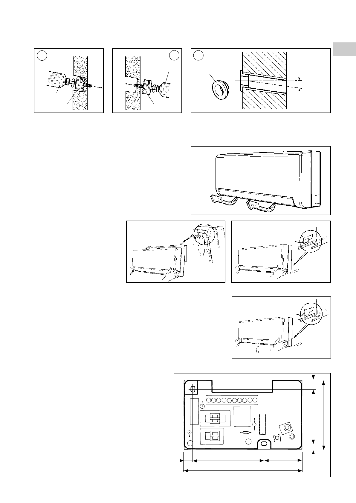
3.3 DRILLING THE HOLES FOR THE PIPES
(for pipes entering through the rear of the air handler)
• Using an 80 mm dia. bell saw attachment, drill a hole in the wall for the pipes.
A
Wall Wall
B
C
GB
Inside
Drill
80 mm dia.
bell saw
attachment
A - Start drilling (at a slight
angle) from the inside.
Outside
Inside
B -
Complete the drilling from
the outside, keeping to
the same angle.
Outside
3.4 HOOKING OF THE INTERNAL UNIT
• Remove the foam packing-pieces in the baffle.
• Hook the air handler on the support
plate according to the sketch
opposite.
• Connect the water pipes (see § 4).
• Run in any electric cables (see § 4).
• Then, press on the bottom of the unit
in order to engage the bottom hooks
in the holes in the support plate.
Hooking
Drill
80 mm dia.
bell saw
attachment
Trim
5 - 10 mm
C - Put in a plastic tube and adapt it to suit. Fix the trim
which is part of the equipment.
3.5 UNHOOKING THE INTERNAL UNIT
• In order to unhook the unit from the support plate, push the unit upwards and pull
it towards you. The hooks are then released from the support plate.
3.6 FIXING THE ROOM THERMOSTAT
• Remove the setting wheel in order to reveal the thermostat cover fixing screw.
• Remove the cover.
• Fix the thermostat using 2 screws (dimensions in
accordance with sketch opposite).
POSITIONING THE THERMOSTAT
• Fixing height: approx. 1.50 m above the floor.
• Avoid draughts from doors and windows.
• Also make sure that the thermostat is in the premises'
normal convection currents, and that it is not fitted inside
shelving or covered by curtains.
• All unwanted heat sources adversely aff ect control; a void
therefore sunlight, the proximity of supplementary
heaters, lights, chimneys, television sets, etc...
869 36
113
8,5
53,55
67
9

4 - CONNECTIONS
GB
4.1 CONNECTING THE CONDENSATE DISCHARGE PIPE
(For air handlers which can operate in cooling mode)
• Connect the condensate pipe to a discharge pipe.
• Fix the two pipes using adhesive tape:
- MW 2, MW 3: Ø 18 mm.
- MW 4, MW 5: Ø 26 mm.
• For air handlers equipped with a condensate lift system, the pump discharge is
connected to a flexible PVC pipe of internal diameter 6 mm, equipped with a splined
connector.
See the "Technical Manual" for the pressures available at the discharge.
IMPORTANT NOTE
• If the end of the condensate discharge pipe goes into the
water and forms a trap, the flow will not be correct and the
condensate will flow in the internal unit (see drawing
opposite).
• Check that the condensate is discharged smoothly.
• Seal the hole in the wall through which the pipes pass in
order to prevent water entering.
Slope
Condensate discharge
pipe
Trap
Adhesive
tape
Condensate
discharge
Sealing
compound
Immersion
• Using a bottle, pour water into the condensate tray in order
to ensure that the water is correctly discharged.
4.2 HYDRAULIC CONNECTION
• MW can be connected either with metric copper pipe or with PER
(interlaced polyethylene).
• Diameter of the pipes to be used:
- MW 2 and MW 3:
- copper pipe 10/12 or
- PER pipe 10/12
- MW 4 and MW 5:
- copper pipe 14/16 or
- PER pipe 13/16
• Adaptors for copper pipe or PER pipe are supplied with the air handler.
Copper pipe
P.E.R. pipe
4.2.1 ORIENTATION OF THE PIPES
• For orientations 1 cut the plate (in
order to put the pipes through leaving
the contour free from any roughness).
• Keep the piece of plate cut for possible later use.
10
1
2
Cover

4.2.2 INSTALLATION WITH HORIZONTAL
CONNECTIONS
• Before fitting the unit on the support plate, connect the
condensate discharge pipe and the connecting pipes and
connect them using adhesive tape.
• Install them in the custom-made housing. Leave the ins-
Insulation
tallation clear along the front.
Pipes
4.2.3 INSULATION OF PIPES
• The insulation concerns the water return and inlet pipes.
• Use polyethylene sheathing at least 6 mm thick.
• After connecting the pipes and checking for leaks, put the insulating sleeves on the
fittings and force them against the cassette in order to prevent condensation.
Note : This operation must be done carefully to avoid any risk of condensation.
4.2.4 PURGING THE AIR HANDLER'S WATER CIRCUIT
• Done by means of a purge screw located on the water coil's header.
• To have access to the screw, remove the air handler's cover.
GB
Electrical cables
(if applicable)
Condensate
pipe
Insulation
MW 2
MW 3
• Then act on the purge screw.
4.3 ELECTRICAL CONNECTIONS
4.3.1. PRINCIPLE
• Control by action on ventilation.
MW 4
MW 5
Purge screw
1
7
2
5
6
312
3
°C
20
15
25
30
4
(*) To be fitted only for a unit operating in cooling and in heating.
1 - Power supply and protection device
(not supplied)
2 - Power cable
(not supplied)
3 - Thermostat
4 - Control cable
(not supplied)
(*)
5 - Cooling/heating change-over contact
(not supplied - integrated in MH)
6 - Cooling/heating change-over control
cable
(not supplied)
7 - Air handler
11

GB
4.3.2. POWER SUPPLY
• 230V / 1+Earth / 50Hz power supply from a power supply
and protection device (not included) in accordance with
with the rules in force especially NFC 15-100 CEI 364.
• The voltage variation tolerance is + or - 10 % during
operation.
• The power cable must be fixed.
• Section of an air handler's power cable: 3G 1.5 mm
• Current consumption of an air handler (with condensate
pump):
Max. current A
MW 2
0.25
MW 3
0.25
MW 4
0.45
2.
MW 5
0.5
• Preparation of the cable (see sketch below).
• Connection to the air handler according to the indications
and diagrams below.
Air handler side
655
4.3.3. CONTROL
• Connection of the thermostat to the
air handler by cable 6 x 0.75 mm
2
.
655
• The power cable must be fixed.
• Preparation of the cable (see sketches opposite).
• Connections according to the indications and diagrams in § 4.3.5.
Air handler side Thermostat side
4.3.4. DETAIL OF THE ELECTRICAL CONNECTION OF THE AIR HANDLER
To have access to the terminal board:
• Remove the air handler's cover (see sketches below).
MW 2
MW 3
• Remove the terminal board access
door (see sketches below).
MW 2
MW 3
MW 4
MW 5
• Then prepare the wires and connect them to the
terminal board.
• Note : on certain devices, the terminals are of the
"cage with spring" type.
Follow the indications below to connect them.
- These terminals take the following wires:
- rigid
- flexible (avoid splicing the strands!)
- with ends
- A single conductor per securing point
- Make sure that the wires are correctly
connected to the terminal board. Incorrect
connection can cause operating problems as
well as overheating which can cause fires.
MW 4
MW 5
40 7
4.3.5 CONNECTION DIAGRAMS
• The wiring of the thermostat shown opposite corresponds
to control in cooling mode with action on the ventila-
tion (standard assembly).
12
COOLING MODE
ONLY
Action on ventilation
Control cable
19
1
3
Thermostat
4
20
21
22
Protected supply
230 V / 1 + T / 50
NPh
Hz
Power supply
cable
U
N
1
3
4
20
21
22
Air handler
MW

• Note :
It is possible to obtain temperature control by actuating a
temperature control valve (not supplied) operating in onoff mode and feeding the terminal unit.
In this case, ventilation is permanent.
Valve power supply: 230 VAC (Max. intensity = 0.5 A inductive).
COOLING MODE
ONLY
Action on valve
19
1
Thermostat
3 6
4
20
21
22
Protected supply
230 V / 1 + T / 50
NPh
Hz
Power supply cable
U
N
N
1
3
4
20
21
22
GB
Air handler
MW
Valve
Control cable
• It is possible to invert the direction of action of control and
thus to change to heating mode by connecting thermostat
terminal 19 to the installation's neutral which can be found
on thermostat terminal 4.
19
Thermostat
1
3
4
20
21
22
HEATING MODE
• For installations which can operate in cooling mode or in
heating mode, it is possible to connect a contact which:
- if it is closed, connects terminal 19 to the installation's
neutral and causes the installation's thermostat to
Air conditioning/
heating change-over
contact
operate in heating.
- if it is open, isolates terminal 19 and causes the control
thermostat to operate in cooling mode.
• This contact (not supplied) can come, for example, from
the hydraulic module MH.
Note : The same contact can control the mode changeover of several room thermostats provided:
- That the length of the wire connecting to the change-
19
1
3
4
20
21
22
19
1
3
4
20
21
22
AIR CONDITIONING/HEATING MODE
over contact does not exceed 150 m (wire of section 1.5 mm2).
- That the neutral on which the change-over contact is connected is the same as the one for the various air handlers.
- Do not run this control cable near power cables in order to avoid interference.
19
1
3
4
20
21
22
4.3.6 REMOTE TEMPERATURE PROBE ACCESSORY
• Enables the control thermostat to be put outside the premises to be air-conditioned.
The probe connects to the thermostat.
• Fixing:
- Make sure that the installation is switched off.
- Open the probe case cover.
- Fix the probe case in the required place, following these rules:
- Avoid draughts
- Avoid any unwanted heat source which could affect the probe (sunlight, pro ximity
of supplementary heaters, lights, chimneys, television sets, etc.)
- Make sure that the probe is in the normal convection currents.
• Remove the cover of the control thermostat case.
• Remove the probe inside the thermostat shown opposite
(by cutting this component's fixing lugs using pliers).
27
71
71
Probe
13

• Connect as indicated:
- Max. length of cable: 50 m on 1.5 mm
2
2
4
GB
• Use shielded cable if the latter runs next to power cables.
• Refit the protective covers.
5 - STARTING
IMPORTANT
Before doing any work on the installation, make sure it is switched off and put out of bounds.
5.1 PRELIMINARY CHECKS
Make sure:
• That the water circulates correctly in the air handler.
• That the heat exchanger has been purged.
• That the fittings are correctly tightened.
• That there are no leaks.
• That the air handler is well fixed.
• That the power cables are well fixed to their connection
terminals.
• That the electric cables are properly insulated from any
pieces of sheet or metal parts which could damage them.
• That the unit is connected to earth.
• That no tools or any other objects have been left in the
units (specially form packing-pieces in the discharge
louvers).
• That the filter is correctly fitted.
• That the condensate discharge outlet is correctly
connected.
• That the condensate collection tank is clean. Particles can
damage the condensate lift pump (if fitted).
5.2 SWITCH ON THE UNIT
• Using the isolation and protection device.
5.3 STARTING
• Through the On/Off switch located on the room thermostat.
• Select one of the three ventilation speeds using the switch
provided for this purpose on the room thermostat.
• Move the temperature setting wheel in order to check the
operation and direction of action of control (*):
- In cooling mode, the fan is operated if the ambient
temperature is above the setpoint.
- In heating mode, the fan is operated if the ambient
temperature is below the setpoint.
• Adjust the temperature setpoint value to the required value.
• If necessary, adjust the position of the vertical deflection
louvre using the "SWEEP" switch on the front of the air
handler (take care of flap movements).
Do not move the flap by hand, as it is motorised.
(*) In the case of adjustment on the valve, ventilation is perma-
nent
4
Probe
Connecting cable
(not included)
11
Thermostat
Note:
A fuse on the printed circuit board next to the air handler's
terminal board protects the circuits (see diagram)
Fuse rating : 2A GI 250 V
Fuse size : 5 x 20
5.4 CONDENSATE LIFT PUMP SYSTEM
Factory-fitted accessory.
• It consists of a float type water detection unit which receives
the water collected by the collection tank placed under the
heat exchanger and of a pump unit which sucks the water
from the detection unit.
• The pump's discharge is to be connected as indicated in §
4.1.
• It is necessary to clean and/or change the filter in the
detection unit (frequency according to handler's operating
conditions). See § 6 - maintenance.
• 5 spare filters are supplied with the air handler.
• When reassembling, make sure that:
- the unit is perfectly level
- the float is not stuck (and its locating stud is facing
upwards)
- the pipes are correctly connected (no leaks).
CAUTION :
Stop the air-conditioning system 30 minutes before any
switching off of terminal units, in order to discharge residual
condensates (and avoid inadvertent overflows).
Vent pipe
Suction of
condensates
Inlet for
condensates
Locating stud
Filter
Float
Cable
14

6 - MAINTENANCE
IMPORTANT
Before doing any work on the installation, check that the power supply is switched off and secured
• Air filter: Clean every two weeks. See “Operating
Manual”.
. External unit air exchanger: Cleaning recommended
once a year.
. Electric connections: Once a year, check that the
electric wires are well fastened to their terminals.
condensates
. Electric box : Dusting is recommended once a year.
• Condensate pumping system: This requires regular
specific maintenance.
- The level detection unit must be cleaned and its filter
Inlet for
condensates
replaced regularly (the frequency depends on the operating
conditions) (see fig. below).
- Clean with water containing 5% bleach.
- The device is delivered with 5 replacement filters.
• When reassembling, make sure:
Locating stud
- that the detection unit is horizontal,
- that the float is clean and not jammed (and that its polarising slot is directed upwards),
- that the pipes are clean and correctly connected (no leaking),
- that the assembly operates correctly by testing it.
Vent pipe
Suction of
Filter
GB
Float
Cable
7 - WIRING DIAGRAM
MW 2 - MW 3 - MW 4 - MW 5
Power supply 230/1/50
Remote sensor
(option)
4 11
19
4
1
T
REMOTE CONTROL
ON/OFF
LS
MS
HS
2
3
20
21
22
20
21
22
10 05 357 - 00
F1
U
2A
N
C2/1
C1/1
C1/2
C2/4
4
1
S1
2
1
N
P
C2/2
P1
C
NC
3
4
C2/3
M1
3
C3/6
C2
C3/5
C3/4
P
M
M2
J
L
G
C3/3
C3/2
W
C3/1
M1 Louvre motor
M2 Fan
P1 Condensate pump (as accessory)
C2 Capacitor of M2
NOTE :
Terminal 19 not connected: control operates in COOLING mode.
Terminal 19 connected to the installation's neutral (terminal 4): control oper ates
in HEATING mode.
F1 Control circuit fuse
S1 Louvre switch
Standard assembly with control by actuating the ventilation.
15

F
GB
I
E
D
En el interés de mejoras constantes, nuestros productos pueden modificarse sin aviso prévio.
R.D. 28 Reyrieux BP 131 01601 Trévoux CEDEX France
Tél. 33 4 74 00 92 92 - Fax. 33 4 74 00 42 00
R.C.S. Bourg-en-Bresse B 759 200 728
 Loading...