

Technibel MCW1B5XAB, MPW1B5XAA, MPW2B5XAA, MCW3B5XAB, MPW3B5XAA Technical Data & Service Manual
...Page 1

TECHNICAL DATA
& SERVICE MANUAL
INDOOR UNIT:
MCW1B5XAB MPW1B5XAA
MCW2B5XAB MPW2B5XAA
MCW3B5XAB MPW3B5XAA
MCW4B5XAB MPW4B5XAA
SPLIT SYSTEM AIR CONDITIONER
0.8180.566.1 April 2011
MCW2B5XAB 38.7104.027
MCW3B5XAB 38.7104.028
MCW4B5XAB 38.7104.029
MPW1B5XAA 38.7104.040
MPW2B5XAA
Model No. Product Code No.
MCW1B5XAB 38.7104.026
MPW3B5XAA
MPW4B5XAA
38.7104.043
38.7104.045
38.7104.047
Page 2

Page
1. SPECIFICATIONS 3
1-1 Unit specifications 3
1-2 Major Component specifications 7
1-3 Other Component specifications 11
2. DIMENSIONAL DATA 12
3. ELECTRICAL DATA 13
3-1 Electric Wiring Diagrams 13
3-2 Jumpers Configuration 14
3-3 Contacts for Building Automation 16
3-4 Maintenance 17
4. FUNCTION 18
4-1 Cool Mode Operation 18
4-2 Heat Mode Operation 19
4-3 Auto (cool/heat) Mode Operation 20
4-4 Dry Mode Operation 21
4-5 Fan Mode Operation 21
4-6 Auto Fan Speed 21
4-7 Forced Mode 22
4-8 Protection Operation in Heat Mode 22
4-9 I Feel Function 24
4-10 Night Function 24
4-11 Diagnostic 25
5. CHECKING ELETRICAL COMPONENTS 26
5-1 Measurement of Insulation Resistance 26
5-2 Checking Continuity of Fuse on PCB Ass'y 27
Table of Contents
2
Page 3

1. SPECIFICATIONS
1-1 Unit Specifications
MCW1B5XAB MPW1B5XAA
Power source
Performance
Input kW
Running Amps A
Total cooling capacity (1) High/Med./Low
kW
Sensible cooling capacity (1) High/Med./Low
kW
Heating capacity (2) High/Med./Low
kW
Air circulation High/Med./Low m³/h
Features
Controls/Temperature controls
Control unit
Timer
Fan speed
Airflow direction Horizontal
Vertical
Water FLOW in cooling
High/Med./Low
l/h
Pressure drop on water in cooling (1)
High/Med./Low
kPa
Pressure drop on water in heating (2) High kPa
Air Filter
Power noise level High/Med./Low dB-A
Water tubing connections
Air clean filter
3-Way valve + By-pass (1/2 gas male, KVS 1,6, 230 NC)
Dimensions & Wei
g
ht
Package dimensions Height mm
MCW
Width mm
Depth mm
Shipping volume
m
3
Package dimensions Height mm
MPW
Width mm
Depth mm
Shipping volume
m
3
Weight Net kg
Shipping kg
DATA SUBJECT TO CHANGE WITHOUT NOTICE
(1)
Air inlet 27°C (D.B.) / 19°C (W.B.); Water inlet 7°C; Water outlet 12°C
(2)
Air inlet 20°C; Water inlet 50°C (same water capacity as in conditions (1))
OPERATION LIMITS
Min. water inlet temperature 4°C Min. air recirculation temperature 5°C
Max. water inlet temperature 60°C Max. air recirculation temperature 32°C
Max. operating pressure of hydraulic circuit 16 bar
0,064
11,0
Optional
0,020
0,11
322
855
273
0,075
Manual
1,24/---/0,8
220/---/150
1,72/---/1,11
215/---/135
Microprocessor/ I.C. thermostat
ON/OFF 24 hours
Wireless remote control unit
Optional
1/2" gas female
Washable, polypropylene, class HB (UL94)
41/--/32
230 V - 50 Hz
855
233
8.0
322
16,1/---/5,8
0,94/---/0,58
15,3
3 and Auto
Auto
3
Page 4

MCW2B5XAB MPW2B5XAA
Power source
Performance
Input kW
Running Amps A
Total cooling capacity (1) High/Med./Low
kW
Sensible cooling capacity (1) High/Med./Low
kW
Heating capacity (2) High/Med./Low
kW
Air circulation High/Med./Low m³/h
Features
Controls/Temperature controls
Control unit
Timer
Fan speed
Airflow direction Horizontal
Vertical
Water capacity in cooling
High/Med./Low
l/h
Pressure drop on water in cooling (1)
High/Med./Low
kPa
Pressure drop on water in heating (2) High kPa
Air Filter
Power noise level High/Med./Low dB-A
Water tubing connections
Air clean filter
3-Way valve + By-pass (1/2 gas male, KVS 1,6, 230 NC)
Dimensions & Wei
g
ht
Package dimensions Height mm
MCW
Width mm
Depth mm
Shipping volume
m
3
Package dimensions Height mm
MPW
Width mm
Depth mm
Shipping volume
m
3
Weight Net kg
Shipping kg
DATA SUBJECT TO CHANGE WITHOUT NOTICE
(1)
Air inlet 27°C (D.B.) / 19°C (W.B.); Water inlet 7°C; Water outlet 12°C
(2)
Air inlet 20°C; Water inlet 50°C (same water capacity as in conditions (1))
OPERATION LIMITS
Min. water inlet temperature 4°C Min. air recirculation temperature 5°C
Max. water inlet temperature 60°C Max. air recirculation temperature 32°C
Max. operating pressure of hydraulic circuit 16 bar
0,11
273
0,075
8.0
27,2/---/9,7
26,2
Manual
Auto
290/---/165
855
11,0
233
0,064
322
855
230 V - 50 Hz
Wireless remote control unit
Microprocessor/ I.C. thermostat
1,67/---/0,96
1,30/---/0,74
2,38/---/1,49
270/---/180
0,020
ON/OFF 24 hours
3 and Auto
322
Washable, polypropylene, class HB (UL94)
45/--/35
1/2" gas female
Optional
Optional
4
Page 5

MCW3B5XAB MPW3B5XAA
Power source
Performance
Input kW
Running Amps A
Total cooling capacity (1) High/Med./Low
kW
Sensible cooling capacity (1) High/Med./Low
kW
Heating capacity (2) High/Med./Low
kW
Air circulation High/Med./Low m³/h
Features
Controls/Temperature controls
Control unit
Timer
Fan speed
Airflow direction Horizontal
Vertical
Water capacity in cooling
High/Med./Low
l/h
Pressure drop on water in cooling (1)
High/Med./Low
kPa
Pressure drop on water in heating (2) High kPa
Air Filter
Power noise level High/Med./Low dB-A
Water tubing connections
Air clean filter
3-Way valve + By-pass (1/2 gas male, KVS 1,6, 230 NC)
Dimensions & Wei
g
ht
Package dimensions Height mm
MCW
Width mm
Depth mm
Shipping volume
m
3
Package dimensions Height mm
MPW
Width mm
Depth mm
Shipping volume
m
3
Weight Net kg
Shipping kg
DATA SUBJECT TO CHANGE WITHOUT NOTICE
(1)
Air inlet 27°C (D.B.) / 19°C (W.B.); Water inlet 7°C; Water outlet 12°C
(2)
Air inlet 20°C; Water inlet 50°C (same water capacity as in conditions (1))
OPERATION LIMITS
Min. water inlet temperature 4°C Min. air recirculation temperature 5°C
Max. water inlet temperature 60°C Max. air recirculation temperature 32°C
Max. operating pressure of hydraulic circuit 16 bar
347
Optional
Washable, polypropylene, class HB (UL94)
Optional
20/13/7
19
58/52/46
1/2" gas female
230 V - 50 Hz
3,17/2,53/1,91
2,56/1,89/1,53
4,50/3,50/2,70
510/400/320
0,075
0,35
Microprocessor/ I.C. thermostat
Wireless remote control unit
545/435/330
ON/OFF 24 hours
3 and Auto
Manual
Auto
1065
260
0,096
347
14,0
1065
281
0,104
11,0
5
Page 6

MCW4B5XAB MPW4B5XAA
Power source
Performance
Input kW
Running Amps A
Total cooling capacity (1) High/Med./Low
kW
Sensible cooling capacity (1) High/Med./Low
kW
Heating capacity (2) High/Med./Low
kW
Air circulation High/Med./Low m³/h
Features
Controls/Temperature controls
Control unit
Timer
Fan speed
Airflow direction Horizontal
Vertical
Water capacity in cooling
High/Med./Low
l/h
Pressure drop on water in cooling (1)
High/Med./Low
kPa
Pressure drop on water in heating (2) High kPa
Air Filter
Power noise level High/Med./Low dB-A
Water tubing connections
Air clean filter
3-Way valve + By-pass (1/2 gas male, KVS 1,6, 230 NC)
Dimensions & Wei
g
ht
Package dimensions Height mm
MCW
Width mm
Depth mm
Shipping volume
m
3
Package dimensions Height mm
MPW
Width mm
Depth mm
Shipping volume
m
3
Weight Net kg
Shipping kg
DATA SUBJECT TO CHANGE WITHOUT NOTICE
(1)
Air inlet 27°C (D.B.) / 19°C (W.B.); Water inlet 7°C; Water outlet 12°C
(2)
Air inlet 20°C; Water inlet 50°C (same water capacity as in conditions (1))
OPERATION LIMITS
Min. water inlet temperature 4°C Min. air recirculation temperature 5°C
Max. water inlet temperature 60°C Max. air recirculation temperature 32°C
Max. operating pressure of hydraulic circuit 16 bar
0,40
3,67/3,14/2,62
3,01/2,50/2,12
5,50/4,50/3,70
230 V - 50 Hz
0,080
1/2" gas female
630/540/450
27/20/14
26,0
Optional
Optional
347
1065
710/580/470
Auto
Washable, polypropylene, class HB (UL94)
59/53/48
Wireless remote control unit
ON/OFF 24 hours
3 and Auto
Manual
Microprocessor/ I.C. thermostat
260
0,096
347
1065
281
0,104
11,0
14,0
6
Page 7
1-2 Major Component Specifications
MCW1B5XAB MPW1B5XAA
Controller PCB
Part No.
Controls
Control circuit fuse
Jumper setting JP1..JP5
Remote Control Unit
Fan & Fan Motor
Type
Q'ty ……. Dia. and lenght mm
Fan motor model…Q'ty
No. Of poles…rpm (230 V - 50 Hz, Hi)
Nominal output W
Coil resistance (Ambient temp. 20 °C )
Ω
Safety devices Type
Operating temp. Open °C
Close
Run capacitor µF
VAC
Flap Motor
Type
Model
Rating
Coil resistance (Ambient temp. 25 °C )
Ω
Heat Exch. Coil
Coil
Rows
Fin pitch mm
Face area
m
2
Quantity of water l
DATA SUBJECT TO CHANGE WITHOUT NOTICE
0,095
SAC ON-OFF IDU
SAC W-REM
Cross - flow
KFV4Q-11H5P-S…1
4…1160
Aluminium plate fin / Copper tube
DC 12 V
380 ± 7%
2
1,4
440
MP24Z1
Stepping motor
VLT-WHT: 197,4
10
YEL-ORG: 155,7
Microprocessor
250 V - 3,15 A
1…. Ø 97 / L 617
2,54mm-5pcs
0,30
0,6
-
BRN-WHT: 561,8
VLT-ORG: 63,4
YEL-PNK: 115,9
internal fuse
145 ± 5
7
Page 8
MCW2B5XAB MPW2B5XAA
Controller PCB
Part No.
Controls
Control circuit fuse
Jumper setting JP1..JP5
Remote Control Unit
Fan & Fan Motor
Type
Q'ty ……. Dia. and lenght mm
Fan motor model…Q'ty
No. Of poles…rpm (230 V, Hi)
Nominal output W
Coil resistance (Ambient temp. 20 °C )
Ω
Safety devices Type
Operating temp. Open °C
Close
Run capacitor µF
VAC
Flap Motor
Type
Model
Rating
Coil resistance (Ambient temp. 25 °C )
Ω
Heat Exch. Coil
Coil
Rows
Fin pitch mm
Face area
m
2
Quantity of water l
DATA SUBJECT TO CHANGE WITHOUT NOTICE
0,39
YEL-ORG: 155,7
1
430
YEL-PNK: 115,9
internal fuse
145 ± 5
0,115
Stepping motor
MP24Z1
DC 12 V
380 ± 7%
Aluminium plate fin / Copper tube
2
1,4
250 V - 3,15 A
SAC W-REM
1…. Ø 97 / L 617
Cross - flow
2,54mm-5pcs
SAC ON-OFF IDU
Microprocessor
BRN-WHT: 561,8
VLT-ORG: 63,4
VLT-WHT: 197,4
KFV4Q-11H5P-S…1
4…1160
10
8
Page 9

MCW3B5XAB MPW3B5XAA
Controller PCB
Part No.
Controls
Control circuit fuse
Jumper setting JP1..JP5
Remote Control Unit
Fan & Fan Motor
Type
Q'ty ……. Dia. and lenght mm
Fan motor model…Q'ty
No. Of poles…rpm (230 V, Hi/Me/Lo)
Nominal output W
Coil resistance (Ambient temp. 20 °C )
Ω
Safety devices Type
Operating temp. Open °C
Close
Run capacitor µF
VAC
Flap Motor
Type
Model
Rating
Coil resistance (Ambient temp. 25 °C )
Ω
Heat Exch. Coil
Coil
Rows
Fin pitch mm
Face area
m
2
Quantity of water l
DATA SUBJECT TO CHANGE WITHOUT NOTICE
0,80
YEL-ORG: 73,55
79 ± 15
0,8
440
YEL-PNK: 43,72
termal protector
130 ± 8
0,156
Stepping motor
MP24Z2
DC 12 V
400 ± 7%
Aluminium plate fin / Copper tube
2
1,4
250 V - 3,15 A
SAC W-REM
1…. Ø 90,5 / L 746
Cross - flow
2,54mm-5pcs
SAC ON-OFF IDU
Microprocessor
BRN-WHT: 163,7
VLT-WHT: 68,84
VLT-ORG: 33,16
UF2Q-21SB5P…1
2… 1550/1250/1025
24,07
9
Page 10

MCW4B5XAB MPW4B5XAA
Controller PCB
Part No.
Controls
Control circuit fuse
Jumper setting JP1..JP5
Remote Control Unit
Fan & Fan Motor
Type
Q'ty ……. Dia. and lenght mm
Fan motor model…Q'ty
No. Of poles…rpm (230 V, Hi/Me/Lo)
Nominal output W
Coil resistance (Ambient temp. 20 °C )
Ω
Safety devices Type
Operating temp. Open °C
Close
Run capacitor µF
VAC
Flap Motor
Type
Model
Rating
Coil resistance (Ambient temp. 25 °C )
Ω
Heat Exch. Coil
Coil
Rows
Fin pitch mm
Face area
m
2
Quantity of water l
DATA SUBJECT TO CHANGE WITHOUT NOTICE
0,80
SAC ON-OFF IDU
Microprocessor
250 V - 3,15 A
2,54mm-5pcs
SAC W-REM
Cross - flow
1…. Ø 90,5 / L 746
UF2Q-21SB5P…1
2… 1550/1250/1025
24,07
BRN-WHT: 163,7
VLT-WHT: 68,84
VLT-ORG: 33,16
YEL-ORG: 73,55
YEL-PNK: 43,72
termal protector
130 ± 8
79 ± 15
1,5
440
Stepping motor
MP24Z2
DC 12 V
400 ± 7%
Aluminium plate fin / Copper tube
2
1,4
0,156
10
Page 11

1-3 Other Component Specifications
Trasformer (TR
)
Rating Primary
Secondary
Capacity
Coil resistance
Ω
(
at 25°C
)
Thermal cut-off temp.
Thermistor
(
Coil sensor
)
Resistance
k
Ω
Thermistor ( Room sensor
)
Resistance
k
Ω
A040C5026AA
AC 230 V, 50 Hz
13 V - 5VA
NTC-THERMISTOR
10 at 25 °C
NTC-THERMISTOR
Primary: -
Secondary: -
120°C
10 at 25 °C
11
Page 12

2. DIMENSIONAL DATA
MCW 1 MCW 3 MPW 1 MPW 3
MCW 2 MCW 4 MPW 2 MPW 4
Dimensions
W
mm 805 995 805 995
H mm 270 285 270 285
T mm 181 206 215 240
MCW 1-2 MCW 3-4
MPW 1-2 MPW 3-4
A
mm 99,5 147,5
B mm 58,5 147,5
C mm 41 45
D mm 111 -
E mm 70 -
Water tubing connections:
1/2 gas female
REAR VIEW
H
W
T
Drain hose diam. 18
Centre of tubing
hole (2 places)
E
Diam. 65(1-2)
12
Page 13

3. ELECTRICAL DATA
3-1 Electric Wiring Diagrams
MCW1B5XAB MCW2B5XAB MPW1B5XAA MPW2B5XAA
MCW3B5XAB MCW4B5XAB MPW3B5XAA MPW4B5XAA
13
Page 14

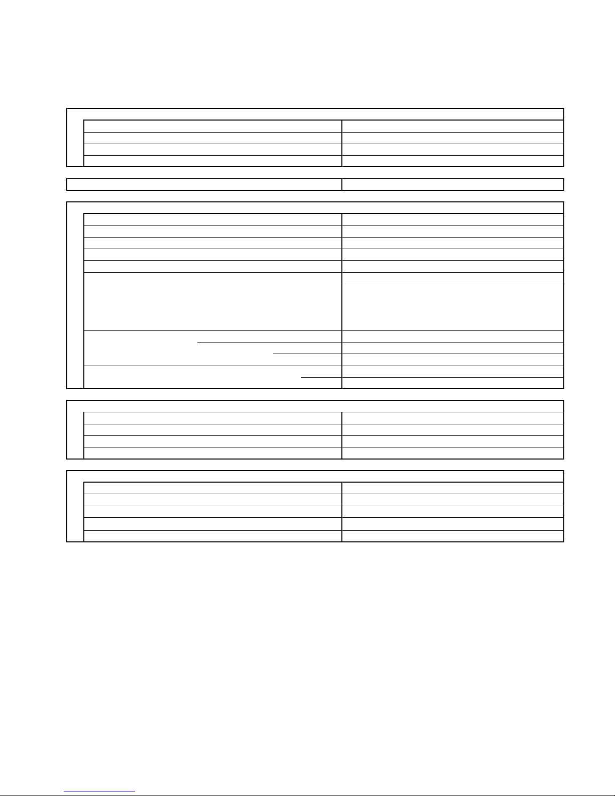
3-2 JUMPERS CONFIGURATION
Jumpers are located on the indoor PCB near the MODE button.
1 - Setting JUMPERS
C = Closed
O = Open
2 - Fonction
A = Available
E = Not available
(when selecting, all leds
blinking)
NOTE: settings different from the factory one must be done by special worker
FACTORY SYSTEM CONFIGURATION:COOLING ONLY WITH VALVE
COOLING ONLY
SYSTEM
FUNCTIONSFUNCTIONS
JUMPERS
14
Page 15
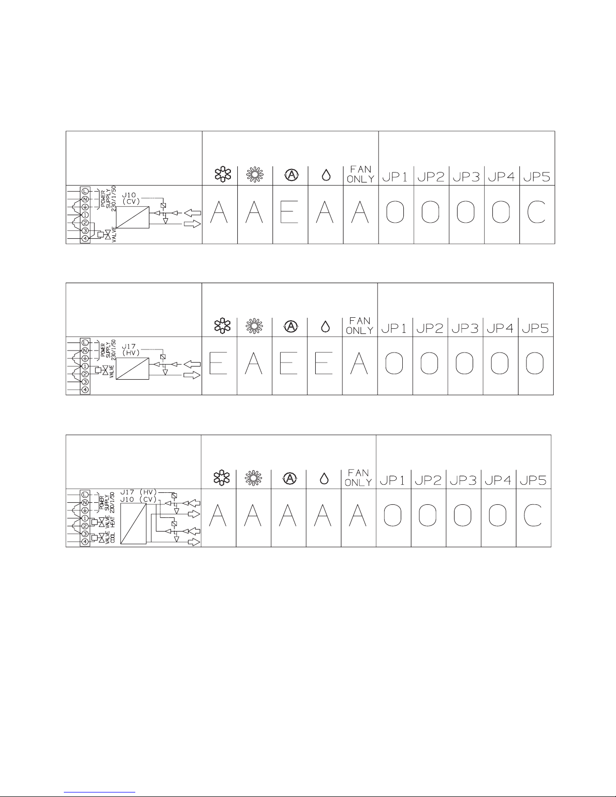
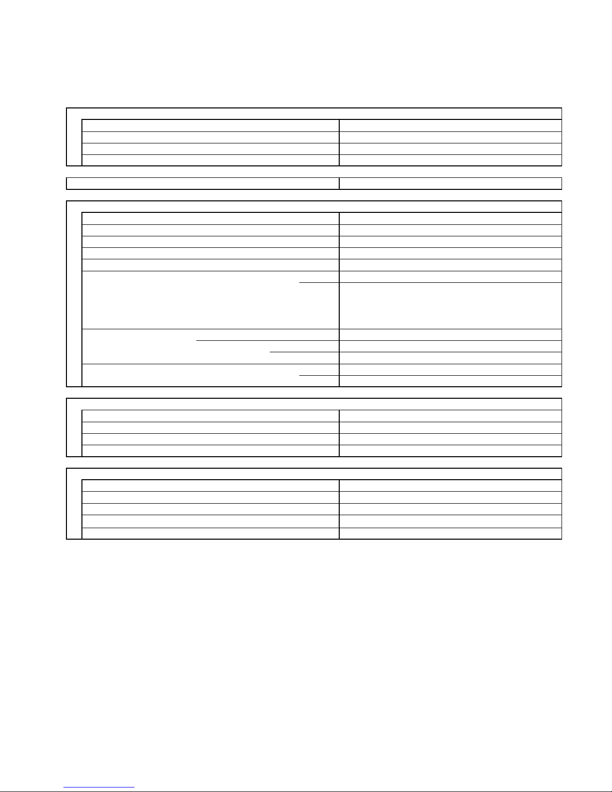
SYSTEM CONFIGURATION:COOLING OR HEATING WITH VALVE
SYSTEM CONFIGURATION:HEATING ONLY WITH VALVE
SYSTEM CONFIGURATION:COOLING WITH VALVE OR HEATING WITH VALVE
COOLING ONLY
SYSTEM
COOLING ONLY
SYSTEM
FUNCTIONS
FUNCTIONS
JUMPERS
JUMPERS
COOLING ONLY
SYSTEM
FUNCTIONS
JUMPERS
15
Page 16

3-3 CONTACTS FOR BUILDING AUTOMATION
3-3.1 INPUT CONTACT (J4 - green)
The status of this input affects system operation according to the following:
Contact OPEN : system does not operate (always OFF) – inputs from wireless remote controller are not processed
Contact CLOSED: system operates in the normal way according to the inputs coming from wireless remote controller
3-3.2 OUTPUT CONTACT (J12)
This connector is directly tied to the contact (normally open) of a power relay which activates every time the following alarm
condition occur:
•
RAT damaged
•
ICT damaged
In this case when alarm happens, on poles 1 and 3 of J12 connector, 220 VAC-50Hz are available.
Max electrical load: 1A- 240VA
C
16
Page 17

3-4 MAINTENANCE
Changing the Address of the Air Conditione
r
In case of more than one air conditioner operating in the same room, it may be necessary to assign an address to each
unit in order to avoid operation conflicts. Address is set acting on the dip-switches located on the indoor PCB and on the
remote controller. The PCB settings must match the corresponding ones on the wireless remote controller.
How to change address of the air conditione
r
Dip switch is located on the indoor PCB near the buzzer.
Set the PCB to the address desidered
As default switches SW1 and SW2 are in off status (PCB factory state).
How to change address on Remote Control Uni
t
Dip switch is located on the battery compartment.
1) Pull out the door and remove the batteries.
2) Set the switch SW1 and SW2 according to the indoor PCB settings
(do not act on SW3 and SW4)
3) Insert the batteries and pull on the door
As default switches SW1 and SW2 are in off status (remote controller factory state).
unit remote control
indoor unit
REMOTE CONTROL
PCB
17
Page 18

4.FUNCTION
4-1 Cool Mode Operation
NOTES
1. In this graph, the FMI is operating with the “Auto Fan Speed” setting. If the user has selected the Low,
Medium or High fan speed, the FMI will run at that speed only.
2. The indoor fan can change speed only after it has operated at the same speed for 30 sec if in AUTO and 1
sec for the other settings (High, Med, Low).
V
ALVE
18
Page 19

4-2 Heat Mode Operation
The Heating mode operation is similar to the Cooling mode operation. The VALVE and FMI are mainly
controlled by the value of (RAT – SPT). In the graph above, the FMI is operating in AUTO speed mode.
Therefore, the FMI speed changes automatically according to the (RT - SPT).
NOTES
1. After VALVE is switched off, the FMI runs for 30s in order to purge heat from the indoor coil.
2. The FMI will not be turned on until the indoor coil temperature is warm enough to prevent the supply of
cool air (see COLD DRAFT PREVENTION mode for details). The indoor fan can change speed only after it
has operated at the same speed for 30 sec if in AUTO and 1 sec for the other settings (High, Med, Low).
V
ALVE
19
Page 20

4-3 Auto (cool/heat) Mode Operation
In Auto Mode, the unit switches automatically between the Auto Cooling and Auto Heating in order to
maintain the room temperature (RAT) at the prescribed set point (SPT).
The switching between the two modes is according to the above graph.
Refer to the sections 5.1 COOLING MODE and 5.2 HEATING MODE for system operation details.
V
ALVE(COOL
)
V
ALVE(HEAT
))
20
Page 21

4-4 Dry Mode Operation
Dry operation remove moisture from indoor air running, in cooling mode, at a low level without reducing the
ambient temperature. This is done cycling ON and OFF indoor and outdoor units according to below.
ROOM DRY LEVEL JP4 OPEN JP4 CLOSED
TEMP
Operation according to Operation according to
≥ SPT+2°C LEVEL 0 COOLING mode COOLING mode
CM off CM off
< SPT+2°C LEVEL 1 FMO on FMO off
≥ SPT-1°C FMI runs at LOW speed FMI runs at LOW speed
RV off RV off
CM off CM off
< SPT-1°C LEVEL 2 FMO switches 3 minutes FMO off
≥ 15°C
on and 9 minutes off
FMI switches LL and L FMI switches LL and L
during FMO operation
(3 MIN. on and 9 OFF)
RV off RV off
CM off CM off
< 15°C DRY OFF ZONE FMO off FMO off
FMI off FMI off
RV off RV off
SPT = Set Point Temperature
4-5 Fan Mode Operation
With this mode, the indoor fan is turned on while cooling and heating valve stay off all the time. The user can
select between 3 speeds: HIGH, MEDIUM and LOW.
4-6 Auto Fan speed
With this option selected, the indoor fan speed changes automatically according to the difference between
the detected air temperature (RAT sensor) and the set point (SPT):
COOLING MODE
2 ≤ (RAT – SPT):
HIGH speed
1 ≤ (RAT – SPT) < 2: MEDIUM speed
(RAT – SPT) < 1: LOW speed
HEATING MODE
2 ≤ (SPT - RAT):
HIGH speed
(SPT - RAT) < 2: MEDIUM speed
NOTE
SPT = Set Point Temperature
21
Page 22

4-7 Forced Mode
In this mode the system operates (COOLING or HEATING mode – fixed settings) or is switched off by
means of the MODE button of the indoor unit control board. The operation modes can be selected
pressing the button in a cyclic way (OFF Ö COOL Ö HEAT Ö OFF…). The settings are:
COOLING mode
SET POINT temperature = 25°C
FAN SPEED = HIGH
HEATING mod
e
SET POINT temperature = 21°C
FAN SPEED = HIGH
4-8 Protection operations in Heat Mode
5-8.1 Cold draft
This feature prevents the supply of cold air forcing the indoor fan to a speed which cannot be changed
by the user. As soon as the protection mode is exited speed can be changed manually through the
remote controller. The protection acts in the following
22
Page 23

4-8.2 Overhea
t
This feature prevents the build up of high pressure in the indoor heat exchanger during heating
operation
A (°C)
65
B (°C)
55
A
B
VALVE (HEAT)VALVE (HEAT)
23
Page 24

4-9 I FEEL Function
As standard configuration the air conditioner operates detecting the room temperature through the sensor
equipped in the wireless remote controller (icon I FEEL shown on the display). This feature provides a
personalised environment since the temperature can be detected where the remote controller is located.
It is possible to de-activate this option pressing the I FEEL button on the remote controller.
In this case the I FEEL icon is no longer displayed and room temperature is detected through the sensor
included in the indoor unit.
4-10 NIGHT Function
When this function is active, room temperature changes automatically to compensate for body temperature
variations while sleeping. After 10 hours of operation system switches automatically to OFF state.
This mode of operation is available both in COOLING and HEATING mode.
24
Page 25

4-11 Diagnostic
With this feature is possible to have a visual signal that a trouble is occurring.
This mode is always active and the signalling is made through the display board LEDS .
In case of no troubles the LEDS status follows its normal function.
NOTES
The troubles are showed according a priority list that is in case of more than one
trouble present, is always showed, at first, the one with the highest priority (1 2 3 etc).
Sensor damaged means a situation where sensor is short-circuited or opened.
In case of damaged sensors, the system (CM, FMO, FMI etc), if in OFF state, does not start.
Priority TROUBLE
LD1(stby) LD2(opr) LD3(timer)
2 RAT damaged F O O
3 ICT damaged F F O
4 WRONG MODE F F F
SELECTED
O = LED off
z = LED on
F = LED blinking
WARNING: Priority 4 only for COOLING
LEDS status Effects
System does not operate
System does not operate
25
Page 26
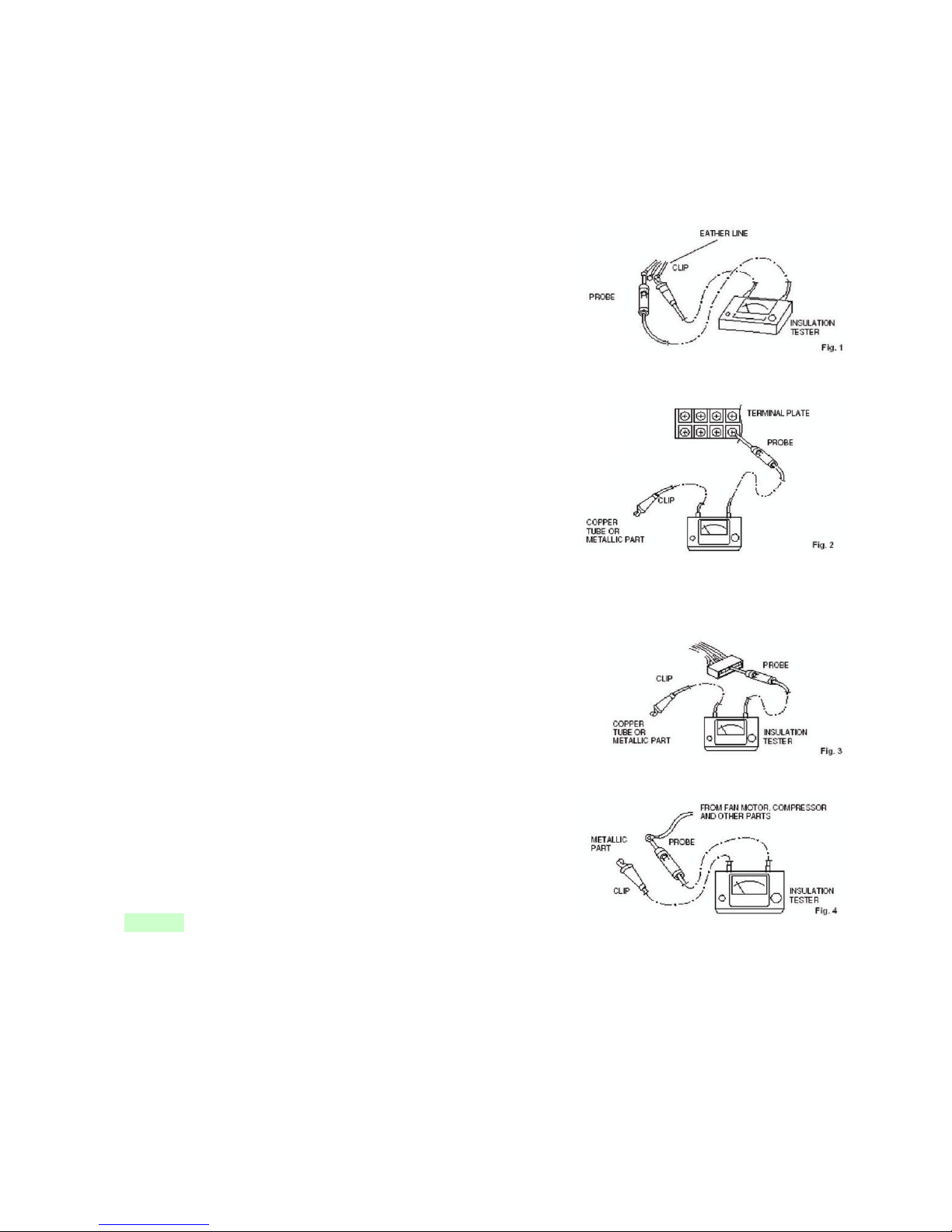
5 CHECKING ELECTRICAL COMPONENTS
5-1 Measurement of Insulation Resistance
The insulation is in good condition if the resistance exceeds 1 MOhm
a) Power Supply Wires
Clamp the earthed wire of the power supply wires
with the lead clip of the insulation resistance tester
and measure the resistance by placing a probe on
either of the power wires (fig.1).
Then measure the resistance between the earthed
wire and the other power wires (fig.1).
b) Unit
Clamp an alluminium plate fin or copper tube with
the lead clip of the insulation resistance tester and
measure the resistance by placing a probe on N terminal,
and then on Lterminal the terminal plate (fig.2)
c) Measurement of Insulation Resistance
for Electrical Parts
Disconnect the lead wires of the disired electric
part from terminal plate, PCB assy, capacitor, etc.
Similary disconnect the connector. Then measure
the insulation resistance (fig.1 to 4).
Refer to electric wiring diagram.
NOTE
If the probe cannot enter the poles because the hole is too narrow
then use a probe with a thinner pin.
26
Page 27
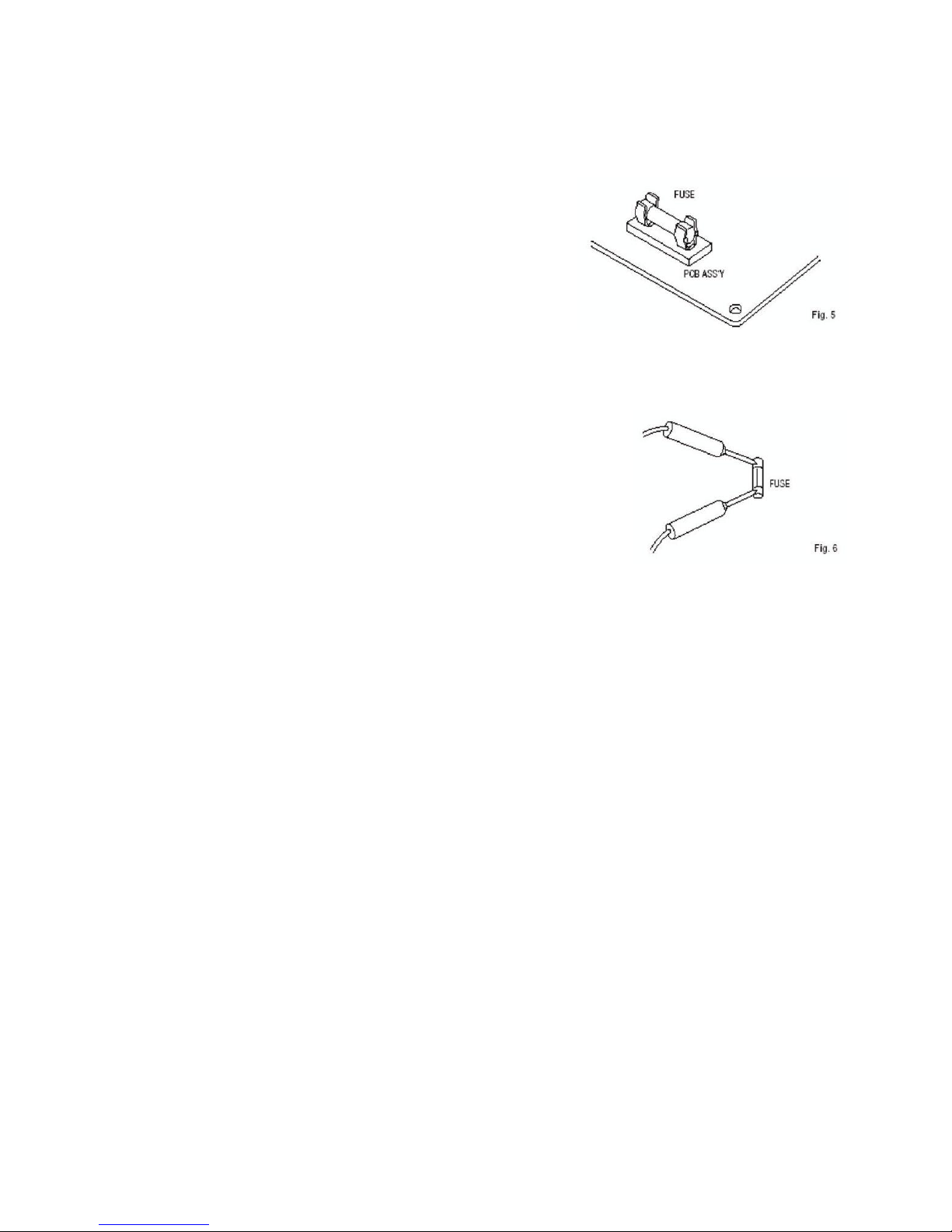
5-2 Checking Continuity of fuse on PCB assy
Remove PCB assy from electrical component box (fig.5)
Then pull out the fuse from PCB assy
Check continuity of fuse by the multimeter (fig.6)
27
Page 28

R.D. 28 Reyrieux BP 131 - 01601 Trévoux CEDEX France
Tél. 04.74.00.92.92 - Fax 04.74.00.42.00
R.C.S. Bourg-en-Bresse B 759 200 728
 Loading...