

Page 1
m1000™ Operating Manual Addendum
for the Advanced Operator
m1000™ Operating Manual Addendum, 392813, en, V1.1
Page 2

Manufacturer Address
Tecan Schweiz AG
Seestrasse 103
CH-8708 Männedorf
Switzerland
Distributor Address
Abbott Laboratories
Abbott Park, IL 60064
USA
Document Status Sheet
Title: m1000™ Operating Manual Addendum for the Advanced Operator
ID: 392813
Version Revision Issue Major changes
1 0 may 2003 First issue
1 1 LiHa/RoMa Calibration Procedure updates
New Procedure: Move Plate Test.
© 2003, Tecan Schweiz AG, Switzerland, all rights reserved
Information contained in this document is subject to change without notice.
Pictorial Disclaimer
The screens and figures contained in this manual are for information and illustration purposes only. Abbott Laboratories makes no representations or warranties about the accuracy and reliability of the information on the screens and figures in this manual; their information is
not to be used for clinical or maintenance evaluation.
Page 3

Table of Contents
m1000™ Operating Manual Addendum ....................................................... 1
Notices and Symbols .....................................................................................2
NAT Admin Software ...................................................................................... 4
Start NAT Admin ............................................................................................. 5
NAT Worktable ................................................................................................ 6
NAT Options ...................................................................................................7
Table of Contents
Database Maintenance ................................................................................... 7
Restore Database ........................................................................................... 8
Temperature Check ........................................................................................ 9
NAT Teach Worktable Racks and Locations ............................................. 10
Calibrate the LiHa .........................................................................................11
Calibrating the DiTi rack carriers for the LiHa ...........................................15
Removing the DiTi Reference Tip ...............................................................17
Calibrate the RoMa .......................................................................................18
Calibrating the DiTi rack carriers for the RoMa ......................................... 20
Calibrating the DiTi rack shelves for the RoMa .........................................22
Fine-tuning the DiTi rack carriers for the LiHa .......................................... 23
Move Plate Test ............................................................................................25
Disconnect from the Instrument .................................................................25
GENESIS Setup & Service Procedures ...................................................... 26
NAT MBS Worktable ..................................................................................... 27
m1000™ Operating Manual Addendum, 392813, en, V1.1 iii
Page 4

Table of Contents
Initialise Instrument ......................................................................................29
Dilutor Tool ....................................................................................................30
Door Lock Check ..........................................................................................32
FaWa Test ......................................................................................................36
Liquid Detection Test ...................................................................................40
Lower DiTi Eject Test ...................................................................................43
PosID Test .....................................................................................................46
iv m1000™ Operating Manual Addendum, 392813, en, V1.1
Page 5

m1000™ Operating Manual Addendum
Read this information prior to using the NAT Admin or the GENESIS Setup &
Service software features. This information should be used in conjunction with
the m1000™ Operating Manual.
This information is issued by Abbott Diagnostics Division to provide you with
advanced m1000™ information.
Intended Use of Operating Manual Addendum:
This manual supports the operator of the m1000™ with instrument calibration
and troubleshooting procedures.
This manual does not enable the operator to generate user-defined protocols.
It is strongly recommended that operators contact Abbott Laboratories for
assistance with any protocol or process step change.
Categories include:
NAT Admin
NAT Worktable
NAT Options
Database Maintenance
Temperature Check
NAT Teach Worktable
GENESIS Setup & Service procedures
NAT MBS Worktable
Initialise Instrument
Dilutor Tool
Door Lock Check
FaWa Test
Liquid Detection Test
Lower DiTi Eject Test
PosID Test
User Qualification
The laboratory personnel must be qualified and trained to operate the m1000™.
The operators must fulfill the following qualifications to perform the procedures
described in this Addendum:
They must have a thorough knowledge of the applications run on the system.
They must be familiar with the Good Laboratory Practice guidelines or
equivalent guidelines.
They must have read and understood the instructions in the m1000™
Operating Manual and this Addendum.
m1000™ Operating Manual Addendum, 392813, en, V1.1 1
Note: Abbott offers onsite training for the primary operator. Abbott recommends
that the primary operator attend this primary operator training course.
Page 6
Notices and
Symbols
Warning Notices Used in this Manual
The symbols used for safety-related notices have the following significance:
Warning Symbols
WARNINGS appear as follows:
WARNING
Generally, the triangular warning symbol indicates the possibility of personal injury
or even loss of life if the instructions are not followed.
Whenever possible, the symbol indicates the hazard a person is exposed to more
specifically. The symbols used in this Operating Manual Addendum have the
following significance:
WARNING
Potentially infectious material
Indicates an area where the operator may be exposed to infectious material.
WARNING
Automatically moving parts.
Injuries (crushing, piercing) possible, if the safety panels are not in place.
Before starting the m1000™, make sure that the safety door is closed.
Never operate the instrument without panels on and door closed.
WARNING
Laser Hazard
Identifies a Class II laser product that contains an embedded low power
visible Class II laser diode barcode scanner. Warns against direct viewing into
barcode laser beam or reflections from the beam.
WARNING
Hot Surface Hazard: Identifies an area where the operator may be exposed to hot
surfaces, such as heater zone 1 and heater zone 2.
2 m1000™ Operating Manual Addendum, 392813, en, V1.1
Page 7

ATTENTION Symbols
ATTENTIONS appear as follows:
ATTENTIO N
With the general “Read This!” symbol, ATTENTION indicates the possibility of
equipment damage, malfunctions, or incorrect process results if instructions are
not followed.
m1000™ Operating Manual Addendum, 392813, en, V1.1 3
Page 8
NAT Admin Software
NAT Admin
Software
The NAT Admin software allows you to configure the m1000™ with information to
meet your site’s specific requirements.
WARNING
The Abbott 1 ml Protocol v1.0 cannot be edited.
The use of the Abbott sample preparation kit and the provided Generic 1 ml
Protocol will allow an operator successful RNA separation. The Generic 1 ml
Protocol processes all specimens and controls as samples. Because the NAT
software does not check dependencies of process steps, instrument damage
and/or poor specimen yield and purity may result from any protocol or process
step change. It is strongly recommended that users contact Abbott Laboratories
for assistance with any protocol or process step change. Technical Support may
be limited for any changes to the Generic 1 ml Protocol not recommended by
Abbott Laboratories. The user has sole responsibility to verify and/or validate any
user-defined protocols.
WARNING
Automatically moving parts.
Injuries (crushing, piercing) possible, if the safety panels are not in place.
Before starting the m1000™, make sure that the safety door is closed.
Never operate the instrument without panels on and door closed.
WARNING
Potentially infectious
Instrument parts may be contaminated with potentially infectious materials.
Follow basic biohazard precautions
Wear appropriate personal protective equipment, such as gloves, lab coats
and protective eye wear
WARNING
The operator may be exposed to hazardous chemicals when handling sample
preparation reagents. The exposure to hazardous chemicals is minimized by
following instructions provided in produce-specific labels and product-specific
Material Safety Data Sheets (MSDS). Wear appropriate personal protective
equipment, such as gloves, lab coats, and protective eye wear.
4 m1000™ Operating Manual Addendum, 392813, en, V1.1
Page 9

Start NAT
Admin
The NAT Wizard must be closed to start the NAT Admin.
Select the NAT Admin icon.
The NAT Admin Login screen is displayed.
Enter User Name and Password (case sensitive) and select <OK>.
The NAT Admin main screen is displayed.
m1000™ Operating Manual Addendum, 392813, en, V1.1 5
Page 10
A
X
NAT Worktable The following figure shows the m1000™ worktable locations used in NAT Admin
software:
X
W
V
U
T
S
R
Q
7
N
K
1
H
G
A
J
I
B
L
2
M
3
8
O
P
C
9
E
D
F
Note: Worktable locations are fixed and cannot be changed.
Fig. 1 NAT Admin Worktable
Control Loc
B Input Loc
C Output Loc
D System Fluid
E DiTi Waste
F Liquid Waste
G 1 ml Subsystem Loc Heater Zone 1
H 1 ml Subsystem Loc Heater Zone 2
Q Shelf Loc 1
R Shelf Loc 2
S Shelf Loc 3
T Shelf Loc 4
U Shelf Loc 5
V Shelf Loc 6
W Shelf Loc 7
Shelf Loc 8
I 1 ml Subsystem Loc RT
J 1 ml Subsystem Loc Mag Low
K Plate Carrier 1, Loc 1
L Plate Carrier 1, Loc 2
M Plate Carrier 1, Loc 3
N Plate Carrier 2, Loc 1
O Plate Carrier 2, Loc 2
P Plate Carrier 2, Loc 3
1 Trough Loc 1
2 Trough Loc 2
3 Trough Loc 3
7 Trough Loc 7
8 Trough Loc 8
9 Trough Loc 9
6 m1000™ Operating Manual Addendum, 392813, en, V1.1
Page 11

NAT Options The Options screen allows the operator to configure printers, directories, log
durations, and barcode settings.
Accessing the Options Page:
1 Select the NAT Admin icon.
2 Enter User Name and Password. Select <OK>.
3 The NAT Admin main screen is displayed.
4 Select Options from the NAT Admin main screen.
5 Select Set NAT Options.
Database
Maintenance
Field Description
Default Printer Select the default printer for report printing.
Import Directory Select default directory from which to import files
Export Directory Select default directory to export files.
Days to save log entries Default is 100
Barcode Settings
Code 2/5 Interleaved*
Codabar
Note: Barcode length for Code 2/5 must be an even number of characters. The
*
Configure the appropriate barcode length
Select 2 to 30
Select 1 to 31
barcode length configured should include the check digit and extra character, if
necessary, for an even number of characters.
Database Maintenance is performed daily at 01:00 a.m. in the form of a daily
backup. In the case of a database corruption, a previous database can be
restored.
m1000™ Operating Manual Addendum, 392813, en, V1.1 7
Page 12
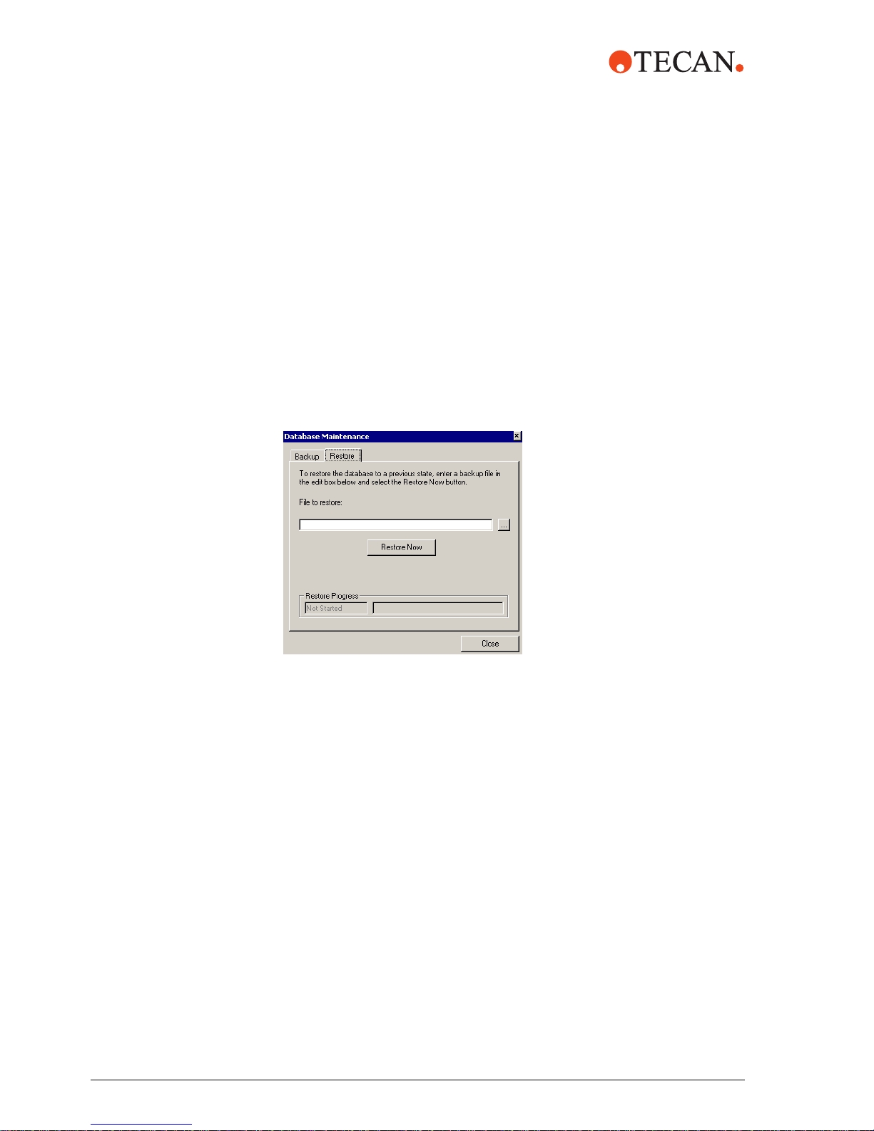
The backup files will be assigned a name based on the date of backup.
For example,
NATMBS_db_200304010100.BAK
NATMBS will always precede the name
20030401 is the backup date: Year/Month/Date
0100 is the backup time
BAK is the file extension
Restore
Database
1 Select the NAT Admin icon.
2 Enter User Name and Password (case sensitive) and select <OK>.
3 The NAT Admin main screen is displayed.
4 Select Tools from the NAT Admin main menu.
5 Select Database Maintenance.
6 Select the file to restore.
7 Select Restore Now.
8 Select Close to exit to the NAT Admin main menu.
8 m1000™ Operating Manual Addendum, 392813, en, V1.1
Page 13
Temperature
Check
The temperature check for the 1 ml subsystem should be performed according to
your laboratory procedures or as directed for troubleshooting. Refer to the
m1000™ Operating Manual, Chapter 8, Troubleshooting, for additional
assistance.
WAR NING
Potentially infectious
Instrument parts may be contaminated with potentially infectious materials.
Follow basic biohazard precautions
Wear appropriate personal protective equipment, such as gloves, lab coats
and protective eye wear
WAR NING
Hot Surface Hazard: Identifies an area where the operator may be exposed to hot
surfaces, such as Heater Zone 1 and Heater Zone 2.
Perform the following steps:
1 Power on the m1000™, if necessary.
2 Select the NAT Wizard icon from the desktop screen. The Main menu is
displayed.
3 From the Main Menu, select Select Protocol.
4 The Authorization dialog window is displayed. Enter your User Name and
password and select > to proceed to the next screen.
5 Select the Abbott 1 ml Protocol v1.0 or the Generic 1 ml Protocol v1.0 to be
run.
6 Place one reaction vessel in the 1 ml subsystem carrier (any location). Add
approximately 1 ml of water, or enough to cover the base of the thermometer.
Place the 1 ml subsystem carrier into heater zone 1.
7 Select > to proceed.
8 The operator is prompted to initiate the Pre-heat protocol to allow heater
zone 1 to reach correct temperature. Select <OK>.
9 Once heater zone 1 reaches the correct operating temperature, the operator
is prompted Heater Zone 1 Achieved Operating Temperature. Select
<OK>.
10 Insert a thermometer into the reaction vessel in heater zone 1. Allow to
equilibrate to 50°C (± 2.5°C). Verify this temperature is 50°C (± 2.5°C).
m1000™ Operating Manual Addendum, 392813, en, V1.1 9
Note: DO NOT place the thermometer into the reaction vessel until the Scan
Rack screen displays.
11 Move the 1 ml subsystem carrier to heater zone 2. Allow the thermometer to
equilibrate to 75°C (± 2.5°C). Verify this temperature is 75°C (± 2.5°C).
12 If the temperature for heater zone 1 and heater zone 2 are not within the
specified range, repeat this procedure. Do not run a sample preparation
protocol until the temperature for both heater zones are correct. Refer to the
m1000™ Operating Manual, Chapter 8, Troubleshooting, for additional
assistance.
13 Remove the thermometer.
14 Select < twice to return to the Main Menu.
Page 14
NAT Teach
Worktable
Racks and
Locations
The liquid handling arm (LiHa) and robotic manipulator arm (RoMa) must be
calibrated with the GENESIS Setup & Service software by an Abbott Field
Service Engineer. In addition, once the GENESIS Setup & Service Worktable
calibrations are performed, the NAT software requires calibration. This can be
performed using the Teach Worktable Racks and Locations screen.
In addition, the vertical and horizontal position for the LiHa and RoMa for carriers
and racks on the m1000™ worktable must be determined by using the NAT
Admin Teach Worktable Racks and Locations procedures.
General Information
WARNING
Automatically moving parts.
Injuries (crushing, piercing) possible, if the safety panels are not in place.
Before starting the m1000™, make sure that the safety door is closed.
Never operate the instrument without panels on and door closed.
WARNING
Potentially infectious
Instrument parts may be contaminated with potentially infectious materials.
Follow basic biohazard precautions
Wear appropriate personal protective equipment, such as gloves, lab coats
and protective eye wear
WARNING
All carriers and racks must be removed from the m1000™ worktable, including the
sample and control racks, reagent trough carriers, 1 ml subsystem carrier, DiTi
racks, waste station chute, and 1.5 ml output tube carriers. Failure to remove
these instrument accessories could result in crashing and damage to the LiHa,
calibration reference tip, and/or the RoMa.
To access the Teach Worktable Racks and Locations screen:
1 Select the NAT Admin icon.
2 Enter User Name and Password and select <OK> to continue. The NAT
Admin screen is displayed.
3 Select File from the NAT Admin main screen.
4 Select Teach Worktable Locations.
5 The Teach Worktable Racks and Locations screen is displayed.
10 m1000™ Operating Manual Addendum, 392813, en, V1.1
Page 15

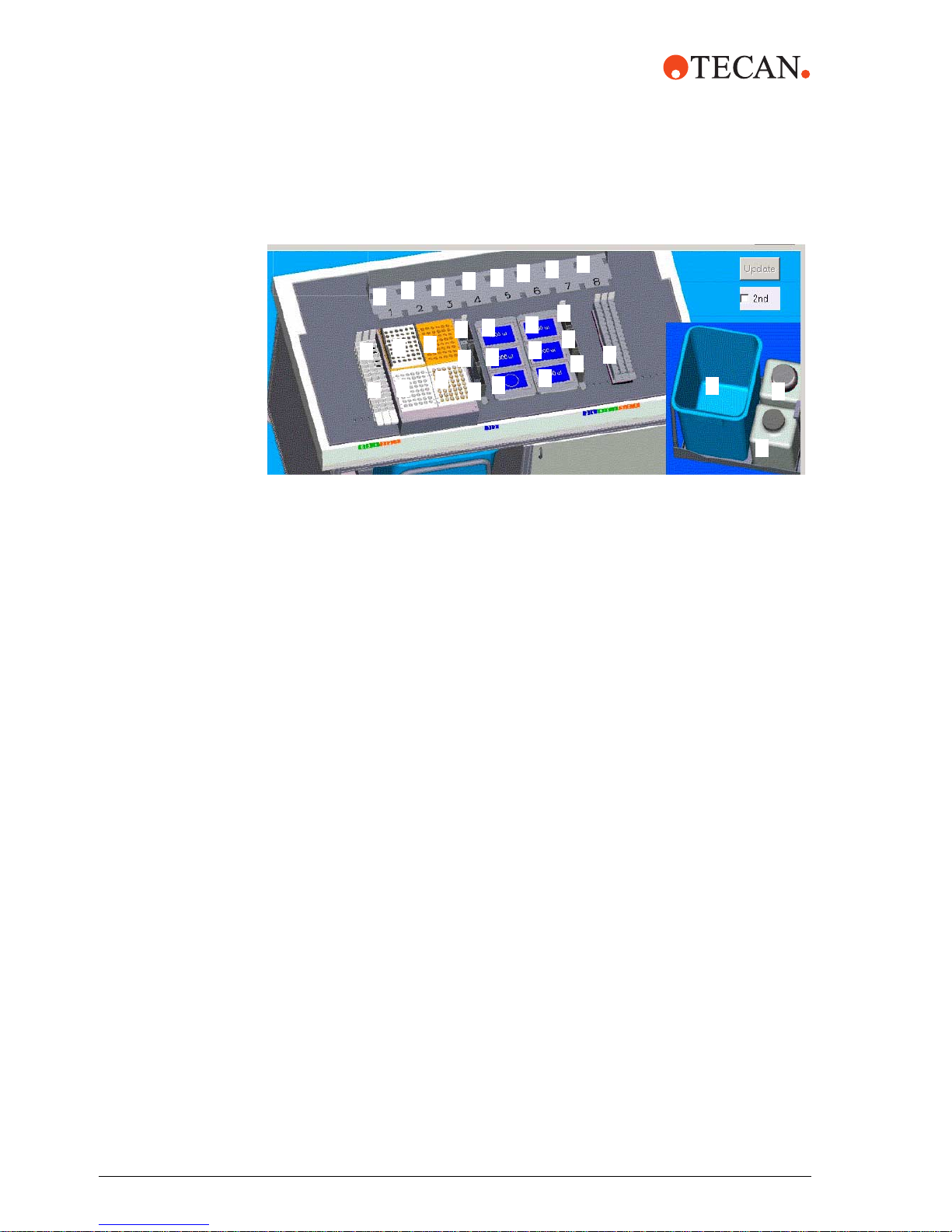
Fig. 2 Teach worktable locations
6 Select Connect to the Instrument.
Connect
to the
Instrument
7 The operator is prompted to remove the sample and control racks, reagent
trough carriers, 1 ml subsystem carrier, DiTi racks, waste station chute, and
1.5 ml output tube carriers. Select <OK>.
8 Once the instrument is connected, the Connect to the Instrument button will
display Disconnect from the instrument.
9 Close the Safety door.
10 Select Initialise all Devices. The LiHa, RoMa, and PosID will move to the
Home position and the Instrument status button will change to Instrument
Status In Init during initialisation.
11 Once Initialization is complete, the Instrument status button will change to
Instrument Status Connected.
Calibrate the
LiHa
m1000™ Operating Manual Addendum, 392813, en, V1.1 11
Calibrating the 1 ml subsystem for the LiHa
During this step, the LiHa is calibrated to correctly aspirate and dispense
specimens, controls, and reagents into the reaction vessels. This calibration will
include X, Y, and Z direction.
Page 16
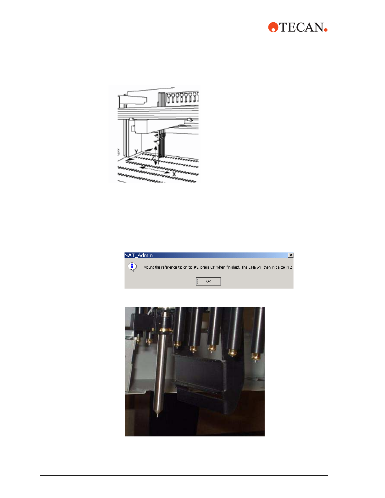
The LiHa can move in three different
directions:
X: arm movement left and right
Y: tip movement and spacing front and rear
Z: range for tip movement up and down.
The target for the 1 ml subsystem is the small indention in the center of each
zone. The reference tip should just touch the target in the X and Y direction and
the tip of the reference tip must touch or just be level with the surface of each
zone.
1 Under Calibrate LiHa, select Mount Reference Tip. The DiTi channels will
separate, allowing easy access to install the reference tip to the third DiTi
channel.
2 The operator is prompted to mount the reference tip to DiTi #3.
Fig. 3 Mounting the Reference Tip
12 m1000™ Operating Manual Addendum, 392813, en, V1.1
Page 17

3 Touch the workstation before touching DiTi cones to discharge static electricity
from your body.
4 Add the reference tip to DiTi #3.
A. Tip ejector tube (black, grooved end up)
B. Tubing extension
C. DiTi cone
– Using the DiTi cone wrench, turn the DiTi cone #3 clockwise to loosen and
remove.
– Remove the black tip ejector tube.
– Disconnect the tubing extension from the tubing.
– Unscrew the stainless steel adapter cylinder.
– Screw the reference tip on the tip adapter and tighten.
– Set aside the DiTi cone, tubing extension, and adapter cylinder.
5 Select <OK> once the reference tip is mounted.
6 Close Safety door.
7 The operator is prompted that the LiHa will move to its Home position. Select
<OK>.
8 Select a calibration point from the list box icon located under the Current
Rack field. The following 1 ml subsystem positions need to be calibrated with
the LiHa using the NAT software:
– 1 ml Heater Zone 1 Calibration Point
– 1 ml Heater Zone 2 Calibration Point
– 1 ml Mag Calibration Point
– 1 ml RT Calibration Point
– 1 ml Mag Rest Calibration Point
m1000™ Operating Manual Addendum, 392813, en, V1.1 13
Page 18

Fig. 4 Calibrate LiHa
9 Select Travel Home to home the LiHa.
10 Select Travel With the LiHa to Location on Carrier. The LiHa will move to
the selected position.
11 Select a Travel increment of 1, 10, or 100, with 1 being the smallest travel
increment and 100 being the largest travel increment.
Fig. 5 1 ml RT Calibration point
– The target for the 1 ml subsystem is the small indention in the center of
– Adjust the reference tip to the X and Y positions first, and then adjust for
– Use the "<" or ">" buttons beside X/Y to move the LiHa in the X direction.
– Use the "^" or "v" buttons beside X/Y to move the LiHa in the Y direction.
– Use the "^" or "v" buttons under Z to move the LiHa in the Z direction.
– Once the reference tip is close to the target, select a target increment of 1
– Once the reference tip is touching the surface of the zone, select Save
12 The position should be verified. Select Travel Home to home the LiHa. Next,
select Travel with the LiHa to Location on Carrier. The LiHa returns to the
new position. If the position is incorrect, repeat steps 8 through 11. If the
position is correct, select Travel Home.
14 m1000™ Operating Manual Addendum, 392813, en, V1.1
each zone. The reference tip should just touch the target in the X and Y
direction and the tip of the reference tip must touch or be level with the
surface of each zone. A piece of paper may be used to ensure a flat
surface.
the Z direction.
to adjust the reference tip as close to the target as possible.
LiHa calibration.
Page 19

13 Once the X, Y, and Z direction are calibrated and saved for one location, then
repeat steps 8 through 12 for each remaining location to be calibrated.
14 The 1 ml Mag Rest Calibration Point is calibrated as described below:
Place the 1 ml subsystem carrier (without cover) in the Mag Rest position,
allowing the carrier to be in the raised position. Close the Safety door.
Select 1 ml Mag Rest Calibration Point.
The operator is prompted to only set the Z direction for the 1 ml Mag Rest
Calibration Point. Select <OK>.
Select Travel with the LiHa to Location on Carrier. To avoid setting the
reference tip in the groove, move the LiHa to the right (X adjustment) by
20 steps. Adjust the reference tip such that the tip is level with or slightly
above the 1 ml subsystem. A piece of paper may be used to adjust the
Z-height. When the Z direction has been calibrated, move the LiHa back to the
left (X adjustment) by 20 steps.
Reference tip
level with main
surface.
Once the reference tip is even with the main surface of the carrier, select Save
LiHa calibration.
The position should be verified. Select Travel Home to home the LiHa. Next,
select Travel with the LiHa to Location on Carrier. The LiHa returns to the
new position.
If the position is incorrect, repeat the above steps.
If the position is correct, select Travel Home.
Remove the 1 ml subsystem carrier from the worktable.
Calibrating the
DiTi rack
carriers for the
During this step, the LiHa is calibrated to correctly pick up disposable tips (DiTis)
used for aspiration and dispense and delivery of DiTis to the DiTi Reuse rack. This
calibration will include X, Y, and Z direction.
LiHa
m1000™ Operating Manual Addendum, 392813, en, V1.1 15
Page 20

The target for the DiTi carrier racks is the left, rear inside corner. The reference tip
should just touch the inside corner in the X and Y direction, without the reference
tip deflecting in either direction. The tip of the reference tip must touch or just be
level with the surface of the DiTi rack carrier.
1 Select a carrier from the list box icon located under the Current Rack field.
The following positions on the worktable need to be calibrated with the LiHa
using the NAT software:
A
B
C
A Plate Carrier 1 Loc 1
B Plate Carrier 1 Loc 2
C Plate Carrier 1 Loc 3
D
E
F
D Plate Carrier 2 Loc 1
E Plate Carrier 2 Loc 2
F Plate Carrier 2 Loc 3
2 Remove the DiTi racks and DiTi reuse racks.
Note: Before calibrating the LiHa, make certain the DiTi rack carrier (plate carrier)
is properly seated on the worktable.
Fig. 6 Calibrate LiHa
3 Close the Safety door.
4 Select Travel With the LiHa to Location on Carrier. The LiHa will move to
the selected position.
5 Select a Travel increment of 1, 10, or 100, with 1 being the smallest travel
increment and 100 being the largest travel increment.
16 m1000™ Operating Manual Addendum, 392813, en, V1.1
Page 21

Reference
tip should
touch the
left rear
inside
corner.
Fig. 7 Plate Carrier 2 Loc 3—LiHa calibration.
The reference tip should be touching the left rear inside corner of the DiTi rack
position carrier.
– Adjust the reference tip to the X and Y positions first, then adjust for the Z
direction.
– Use the "<" or ">" buttons beside X/Y to move the LiHa in the X direction.
– Use the "^" or "v" buttons beside X/Y to move the LiHa in the Y direction.
– Use the "^" or "v" buttons under Z to move the LiHa in the Z direction.
– Once the reference tip is close to the target, select a target increment of 1
to adjust the reference tip as close to the target as possible.
– Once the reference tip is touching the left rear inside corner of the DiTi
rack carrier, select Save LiHa Calibration.
6 The position should be verified. Select Travel Home to home the LiHa. Next,
select Travel with the LiHa to Location on Carrier. The LiHa returns to the
new position. If the position is incorrect, repeat steps 3 through 5. If the
position is correct, select Travel Home.
7 Once the X, Y, and Z direction are saved for one DiTi rack carrier position,
then repeat the steps 1 through 6 for each remaining DiTi rack carrier position
to be set.
8 Once all positions have been calibrated, select Dismount Reference Tip.
The operator is prompted to Remove the Reference Tip. Select <OK>.
Removing the
DiTi Reference
Tip
m1000™ Operating Manual Addendum, 392813, en, V1.1 17
A. Tubing extension
B. Separator ring (white)
C. O-ring (black)
Page 22

Unscrew the reference tip from the tip adapter.
Replace the stainless steel adapter cylinder.
Connect the tubing extension to the tubing. Ensure the separator ring and
o-ring are on the tubing extension.
Add the black tip ejector tube with the grooved end up. Secure in place with
the DiTi cone.
Tighten with the DiTi cone wrench.
The operator is prompted that the LiHa will move to the Home position. Select
<OK>.
Calibrate the
RoMa
Calibrating the 1 ml subsystem for the RoMa.
1 During this step, the RoMa is calibrated to correctly pickup the 1 ml subsystem
carrier and move to different positions on the worktable. This calibration will
include X, Y, and Z direction.
2 Select a rack from the list box icon located under the Current Location field.
The following 1 ml subsystem positions need to be calibrated with the RoMa
using the NAT software:
– 1 ml Subsystem Loc Heater Zone 1
– 1 ml Subsystem Loc Heater Zone 2
– 1 ml Subsystem Loc Mag Low
– 1 ml Subsystem Loc RT
– 1 ml Subsystem Loc Rest
Note: 1 ml Subsystem Loc Mag Med and 1 ml Subsystem Loc Mag High will be
automatically calibrated. No calibration is necessary.
18 m1000™ Operating Manual Addendum, 392813, en, V1.1
Page 23

Fig. 8 1 ml subassembly
c
1 ml Subsystem
Loc Heater Zone 1
1 ml Subsystem Lo
Heater Zone 2
1 ml Subsystem
Loc RT
1 ml Subsystem
Loc Mag Low
Fig. 9 Calibrate RoMa
3 Move the 1 ml subsystem carrier with cover on to the position being
calibrated.
4 Close the Safety door.
5 Select Travel With the RoMa to the Location.
6 Select a Travel increment of 1, 10, or 100, with 1 being the smallest travel
increment and 100 being the largest travel increment.
– The RoMa gripper arms should be just below the lip on the sides of the
carrier and centered on both sides of the carrier. The gripper pins on the
RoMa should fit in the indentations on the side of the carrier.
– Use the "<" or ">" buttons beside X/Y to move the RoMa in the X direction.
– Use the "^" or "v" buttons beside X/Y to move the RoMa in the Y direction.
– Use the "^" or "v" buttons under Z to move the RoMa in the Z direction.
– Once the RoMa gripper arms are close to the surface, select a target
increment of 1 to adjust the gripper arms as close to the target as
possible.
– Once the RoMa is positioned, select Save RoMa Calibration.
7 The position should be verified. Select Travel Home to home the RoMa. Next,
select Travel with the RoMa to the Location. The RoMa returns to the new
position. If the position is incorrect, repeat steps 5 through 6. If the position is
correct, select Travel Home.
m1000™ Operating Manual Addendum, 392813, en, V1.1 19
Page 24

The RoMa
gripper pin
should be equal
distance when
viewed from the
interior of the
RoMa.
Fig. 10 1 ml subsystem heater zone 1
8 Once the X, Y, and Z direction are saved for one subsystem position, then
repeat the steps 2 through 7 for each remaining 1 ml subsystem position to be
calibrated.
Calibrating the
DiTi rack
carriers for the
RoMa
During this step, the RoMa is calibrated to correctly pickup DiTi racks to move to
the DiTi rack carrier and the DiTi rack shelves. This calibration will include X, Y,
and Z direction.
1 Select a carrier from the list box icon located under the Current Location
field. The following positions on the worktable need to be calibrated with the
RoMa using the NAT software:
– Plate Carrier 2, Loc 1
– Plate Carrier 2, Loc 2
– Plate Carrier 2, Loc 3
2 Position the DiTi rack being calibrated.
3 Close the Safety door.
4 Select Travel with the RoMa to the Location.
5 Select a Travel increment of 1, 10, 100, with 1 being the smallest travel
increment and 100 being the largest travel increment.
The RoMa gripper arms should be centered on both sides of the DiTi rack and
approximately 1 mm above the surface of the DiTi Rack carrier.
20 m1000™ Operating Manual Addendum, 392813, en, V1.1
Page 25

RoMa gripper pins
should be just
touching the
DiTi rack.
– Use the "<" or ">" buttons beside X/Y to move the RoMa in the X direction.
– Use the "<" or ">" buttons beside X/Y to move the RoMa in the Y direction.
– Use the "^" or "v" buttons under Z to move the RoMa in the Z direction.
– Once the RoMa gripper arms are close to the surface, select a target
increment of 1 to adjust the gripper arms as close to the target as
possible. Once the gripper arms are just touching the surface, raise the
gripper arms approximately 1 mm (10 steps) (Z adjustment).
– Move the RoMa in the X direction so the gripper pins just touch the DiTi
rack.
– Select Save RoMa Calibration.
– The gripper pins should be positioned in the X direction so there is not a
collision with the DiTi rack and the DiTi tray when Travel with the RoMa
to the Location is selected.
6 The position should be verified. Select Travel Home to home the RoMa. Next
select Travel with the RoMa to the Location. The RoMa returns to the new
position. If the position is incorrect, repeat steps 4 through 5. If the position is
correct, select Travel Home.
7 Once the X, Y, and Z direction are saved for one DiTi rack carrier position,
then repeat the steps 1 through 6 for each remaining DiTi rack carrier position
to be calibrated.
m1000™ Operating Manual Addendum, 392813, en, V1.1 21
Fig. 11 Calibrate RoMa
Page 26

Calibrating the
DiTi rack
shelves for the
RoMa
1 Select a carrier from the list box icon located under the Current Location
field. Shelf Loc 1 through Shelf Loc 8 should be calibrated for the RoMa using
the NAT software.
2 Center the DiTi rack in the Shelf location being calibrated.
3 Close the Safety door.
4 Select Travel with the RoMa to the Location.
5 Select a Travel increment of 1, 10, 100, with 1 being the smallest travel
increment and 100 being the largest travel increment.
The RoMa gripper arms should be just touching on the surface of the DiTi rack
shelf (Z adjustment) and centered (X adjustment) on both sides of the rack.
RoMa gripper arms
should be just
touching the surface
of the DiTi shelf and
gripper pins 10
steps from the DiTi
rack.
– Use the "<" or ">" buttons beside X/Y to move the RoMa in the X direction.
– Use the "^" or "v" buttons beside X/Y to move the RoMa in the Y direction.
– Use the "^" or "v" buttons under Z to move the RoMa in the Z direction.
– Once the RoMa gripper arms are close to the surface, select a target
increment of 1 to adjust the gripper arms as close to the target as
possible.
– Once the RoMa gripper pins are touching the DiTi rack, move the gripper
arms 10 steps (Y adjustment) toward the front of the instrument.
– Once the RoMa is positioned, select Save RoMa Calibration.
– For Shelf location 1 only: Once the RoMa gripper pins have been centered
on both sides of the DiTi rack, move to the left 20 steps (X adjustment).
Select Save RoMa Calibration.
6 The position should be verified. Select Travel Home to home the RoMa. Next,
select Travel with the RoMa to the Location. The RoMa returns to the new
position. If the position is incorrect, repeat steps 2 through 5. If the position is
correct, select Travel Home.
7 Once the X, Y, and Z direction are saved for one Shelf location, then repeat
the steps 1 through 6 for each remaining Shelf location to be calibrated.
22 m1000™ Operating Manual Addendum, 392813, en, V1.1
Page 27

Fine-tuning the
DiTi rack
carriers for the
LiHa
During this step, the LiHa is fine-tuned to correctly pick up disposable tips (DiTi)
used for aspiration and dispense and delivery of DiTi to the DiTi Reuse rack.
A
B
C
Fig. 12 Plate Carrier Positions
D
E
F
A Plate Carrier 1, Loc 1
B Plate Carrier 1, Loc 2
C Plate Carrier 1, Loc 3
D Plate Carrier 2, Loc 1
E Plate Carrier 2, Loc 2
F Plate Carrier 2, Loc 3
Check DiTi Locations:
1 Select Disconnect from the Instrument.
2 Select Close to exit to the NAT Admin main menu.
3 Exit NAT Admin.
4 Select the NAT Wizard icon from the desktop screen. The main screen is
displayed.
5 From the Main Menu, select Select Protocol.
6 Enter your User Name and Password and select > to proceed to the next
screen.
7 From the Select Protocol screen, select the Check DiTi Locations protocol
and select > to continue.
8 At the Pre-heat Protocol prompt, select <OK>. Allow up to 20 minutes for
Heater Zone 1 to reach the correct operating temperature.
9 Once Heater Zone 1 reaches temperature, select <OK>.
10 At the Sample screen, add a sample rack with eight barcode labeled tubes to
grid 4, 5, or 6.
11 Select <Scan Rack> and > to continue.
12 At the Reagent Report screen, select > to continue.
m1000™ Operating Manual Addendum, 392813, en, V1.1 23
Page 28

13 At the Load DiTis prompt, select Using Full DiTi Racks. Add full 1000 uL DiTi
racks to Plate Carrier 1, Loc 1 and 2, and Plate Carrier 2, Loc 1 and 2. Add a
full 200 uL DiTi rack to Plate Carrier 2, Loc 3. Add a full 1000 uL DiTi rack to
Plate Carrier 1, Loc 3, the DiTi Reuse Rack.
14 At the checklists, select > to continue.
15 Select <Scan Reagents>.
16 Enter a value for the Reagent Lot ID field and select > to continue.
17 Select <Flush System>. Select > to continue.
18 At the Acknowledge screen, select > to continue.
19 The operator is prompted "Use Full DiTi Boxes only". Select <OK>.
20 The operator is prompted "Plate Carrier 1 Loc 1, 1000 DiTi". Select <OK>.
21 Observe the LiHa as it picks up the disposable tips. Determine if any
adjustment is needed for the DiTi cone to be centered over the DiTis and note
the required adjustment.
Note: The adjustment will be made in Step 33.
22 The Check DiTi Locations protocol will access each of the 6 locations,
prompting the user prior to moving to the next Plate Carrier location. To
proceed with the next location, select <OK>.
23 When the Check DiTi Locations protocol completes, select <Finish>. Enter
your User Name and password and select > to proceed to the next screen.
24 Exit NAT Wizard and select <Exit>.
25 Select <Yes>.
26 Open NAT Admin.
27 Enter your User Name and Password and <OK> to proceed.
28 Select File from the NAT Admin main screen.
29 Select Teach Worktable Locations.
30 Select Connect to the Instrument.
31 Select Initialise all Devices.
Note: This step is only needed if the instrument has NOT been initialized. It is not
necessary to initialize all devices each time you enter NAT Admin unless there
has been an error with a device.
32 Remove the DiTi rack carriers.
33 Select Calibrate LiHa. Select a carrier from the list box icon located under the
Current Rack field. The following positions on the worktable need to be
adjusted for X and Y direction based upon the observations from the Check
DiTi Locations protocol:
– Plate Carrier 1, Loc 1
– Plate Carrier 1, Loc 2
– Plate Carrier 1, Loc 3
– Plate Carrier 2, Loc 1
– Plate Carrier 2, Loc 2
– Plate Carrier 2, Loc 3
Note: Only adjust by 5, 10, 15, or 20 steps. DO NOT adjust the Z direction. Once
each location is adjusted, select Save LiHa Calibration.
34 Raise the Z direction for only Plate Carrier 1, Loc 3 (DiTi Reuse Rack)
28 steps. Select Save LiHa Calibration.
24 m1000™ Operating Manual Addendum, 392813, en, V1.1
Page 29

35 Repeat steps 1 through 33 until all DiTi cones are centered in all DiTi Rack
carrier positions by performing the Check DiTi Locations protocol.
Once the Calibration Procedure has been completed, perform Move Plate Test
and visually observe the LiHa and RoMa for proper positioning.
36 Select Disconnect from the Instrument.
37 Exit NAT Admin.
Move Plate Test The Move Plate Test should be performed after fine-tuning the NAT worktable
using the NAT Teach Worktable Racks and Locations.
1 Access NAT Wizard.
2 Access Main menu.
3 From Main menu, select <Select Protocol>.
4 Enter User Name and Password.
5 Select > to proceed to the next screen.
6 From the Select Protocol screen, select Move Plate Test and > to continue.
7 At the Pre-heat Protocol prompt, select <OK>.
8 Once Heater Zone 1 reaches the correct operating temperature, select <OK>.
9 At the Sample screen, add a sample rack with eight barcode labeled tubes to
grid 4, 5, or 6. Place the 1 ml subsystem carrier in Heater Zone 1 of the 1 ml
Subsystem.
10 Select <Scan Rack> and > to continue.
11 At the Reagent Report screen, select > to continue.
12 At the checklists, select > to continue. Select Using Full DiTi Racks.
13 Select <Scan Reagents>.
14 Enter a value for the Reagent Lot ID field and select > to continue.
15 Select <Flush System>. Select > to continue.
16 At the Acknowledge screen, select > to continue.
17 The RoMa will move the 1 ml subsystem carrier to different locations in the
1 ml subsystem.
18 The operator is prompted “You must have selected <Using Full DiTi Racks>”.
Ensure the DiTi racks are full. Select <OK>.
19 The operator is prompted “Plate Carrier 2, Loc 1 should have a 1000 DiTi
Box”. Ensure a 1000 DiTi rack is in this position. Select <OK>.
20 The operator is prompted “Plate Carrier 2, Loc 3 should have a 200 DiTi Box”.
Ensure a 200 DiTi rack is in this position. Select <OK>.
21 The operator is prompted “The Shelf should be empty”. Remove any DiTi
racks. Select <OK>.
22 If any of the positions of the 1 ml subsystem carrier are not correct, repeat
Calibrating the 1 ml subsystem for the RoMa.
23 If any of the positions of the DiTi rack are not correct or DiTi racks are tilted,
repeat Calibrating DiTi rack shelves for the RoMa.
Disconnect
from the
Instrument
m1000™ Operating Manual Addendum, 392813, en, V1.1 25
Once the LiHa and RoMa have been calibrated for the m1000™ worktable, return
the carriers and racks, including the Waste Station Chute to the m1000™
worktable. Close the safety door and select Disconnect from the Instrument.
Page 30

GENESIS Setup
& Service
Procedures
The following procedures listed in this section use the GENSESIS Setup &
Service software. These procedures are to be used to assist with troubleshooting
the m1000™ instrument.
Initialise Instrument
Dilutor Tool
Door Lock Check
FaWa Test
Liquid Detection Test
Lower DiTi Eject Test
PosID Test
Starting Setup & Service procedures
The NAT Software must be closed to start the Genesis Setup & Service
software.
Start the GENESIS Setup & Service software by selecting the TECAN
icon from the desktop screen. The GENESIS Setup & Service main screen is
displayed.
Tool bar Can be switched
on/off with View → To o l Bar
Menu bar
Status bar Can be switched
on/off with View → Status Bar
The GENESIS Setup & Service main screen is divided into four sections:
Menu bar
Tool bar
Worktable
Status bar
26 m1000™ Operating Manual Addendum, 392813, en, V1.1
Worktable (empty)
Page 31

NAT MBS
Worktable
To perform tests, the GENESIS Setup & Service software needs information
about the location of carriers and racks on the worktable.
To load the NAT MBS (Magnetic Bead Separation) Worktable:
1 Start the GENESIS Setup & Service software by clicking on the
TECAN icon.
.
2 From the GENESIS Setup & Service screen, select System from the menu
bar.
3 Select Load Worktable from the System menu.
4 The Select Worktable screen is displayed. Select NAT MBS Worktable and
then <OK>.
NAT MBS
Worktable
m1000™ Operating Manual Addendum, 392813, en, V1.1 27
Page 32

5 The NAT MBS Worktable is displayed.
Note: Once the NAT MBS Worktable has been opened, it is not necessary to
open the worktable for each procedure.
Fig. 13 NAT MBS Worktable
Description Worktable grid NAT MBS Worktable
C4, C1, C2, C3 1 - 4 Sample and control racks
Heater
R1
R2
R3
R4
W1
Waste, R R
Waste, R M
DiTi Waste
T1
RR
RM
RF
DiTi
RR
RM
RF
Balance 28-37 Balance (not used)
7-17 1 ml subsystem
Heater zone 1
Room temperature zone
Heater zone 2
Magnet zone
18 Waste Station
20 Reagent Trough Carrier
21-26 DiTi Rack Carriers
28 m1000™ Operating Manual Addendum, 392813, en, V1.1
Page 33

Initialise
Instrument
During initialization of the m1000™, all installed subassemblies are moved to their
initial positions.
The PosID and LiHa will move to the left side.
The RoMa will move to the right side.
1 Close the Safety door.
2 Start the GENESIS Setup & Service software by clicking on the
TECAN icon.
3 From the GENESIS Setup & Service main screen, select System from the
menu bar.
4 Select Initialise Instrument from the System menu.
m1000™ Operating Manual Addendum, 392813, en, V1.1 29
Instrument initialization begins and the following message appears:
5 Once Initialization is complete, the GENESIS Setup & Service main screen
is displayed.
Page 34

Dilutor Tool The Dilutor tool procedure checks the dilutors and their associated tubings. Each
dilutor can be activated individually.
1 Start the GENESIS Setup & Service software by clicking on the
TECAN icon.
2 From the GENESIS Setup & Service main screen, select System Devices
from the menu bar.
3 Select LiHa from the System Devices menu.
4 Select Dilutor from the LiHa Panel submenu.
30 m1000™ Operating Manual Addendum, 392813, en, V1.1
Page 35

5 Complete the following fields:
Field Selection
Grid 18
Position Waste
Use Fast Wash Pump
9
6 Close the Safety door.
7 Select one of the following functions:
Selection Function
Flush Initializes all 8 dilutors at one time.
Flush tips once sequentially
The operator is prompted Do you want to
move LiHa above Washstation?
Initializes the dilutor one by one.
Select Yes.
8 Observe the dilutors for movement and leaks
– If the dilutors are leaking, check the plunger screw and syringe screw for
tightness. Also check the valve connections for tightness. Refer to the
m1000™ Operating Manual, Section 7.3.2.
– Change the syringes and/or 3-way valve. Refer to the m1000™ Operating
Manual, Section 7.5.
– Repeat the Dilutor tool.
– If the leaks continue, notify your local Abbott representative.
9 Select Print to print the report. Select <OK> to exit.
m1000™ Operating Manual Addendum, 392813, en, V1.1 31
Page 36

Door Lock
Check
The Door Lock Test checks whether the door lock is working properly.
1 Start the GENESIS Setup & Service software by clicking on the
TECAN icon.
.
2 From the GENESIS Setup & Service main screen, select Options from the
menu bar.
3 Select Access Status Options from the Options menu.
4 The Access/Status Panel screen is displayed.
.
5 Highlight Access Status under Available Devices.
.
6 Select Device Test option under Test.
7 Select the Configuration & Tools tab.
Access Status
Device Test
32 m1000™ Operating Manual Addendum, 392813, en, V1.1
Page 37

8 Select the following options:
Door Lock 1 (left)
Door Lock 2 (right)
9 Select Apply to save the configuration selected.
10 Close the safety door and check the door lock function by selecting Lock and
Unlock for the door lock selected.
11 If the door lock does not respond to the command, repeat the above step. If
the door lock still does not respond, contact your local Abbott representative.
12 Continue to check the door lock function by selecting Start from the
Access/Status Panel.
.
Start
m1000™ Operating Manual Addendum, 392813, en, V1.1 33
Page 38

13 The operator is prompted “Door Lock 1 (left). Please close the main door”.
Select <OK>.
14 The operator is next prompted “Door Lock 1 (left). Check if the left side is
locked now”.
Select <OK> if the left door is locked.
Select Cancel if the left door lock is not locked. Repeat. If the left door is still
not locked, contact your local Abbott representative.
15 The operator is now prompted “Door Lock 1 (left). Check if it is unlocked now”.
Select <OK> if the left door lock is unlocked.
Select Cancel is the left door lock is still locked. Repeat. If the left door lock is
still locked, contact your local Abbott representative.
34 m1000™ Operating Manual Addendum, 392813, en, V1.1
Page 39

16 The operator is prompted “Door Lock 2 (right). Please close the main door”.
Select <OK>.
17 The operator is prompted “Door Lock 2 (right). Check if the right side is locked
now”.
Select <OK> if the right door lock is locked.
Select Cancel if the right door lock is not locked. Repeat. If the right door lock
is not locked, contact your local Abbott representative.
18 The operator is prompted “Door Lock 2 (right). Check if it is unlocked now”.
.
Select <OK> if the right door lock is unlocked.
Select Cancel if the right door lock is still locked. Repeat. If the right door lock
is still locked, contact your local Abbott representative.
m1000™ Operating Manual Addendum, 392813, en, V1.1 35
Page 40

19 The operator is now prompted Test Result: Passed or Test Result: Failed.
20 If Cancel was selected due to the door lock not functioning, then the Door
Lock Test fails. Close the door completely and repeat the Door Lock Test. If
the Door Lock Test fails again, contact your local Abbott representative.
21 Select <OK> from the Access Status Options Process prompt.
22 Select <OK> from the Access/Status Panel to return to the Setup & Service
main menu.
FaWa Test The Fast Wash Pump (FaWa) is used to pump a large amount of liquid at high
speed through the system, usually to flush the liquid system and remove any air
bubbles.
Test Sequence
The Fast Wash Pump test performs the following procedure to test the throughput
of the pump through the tips of DiTi adapters.
The tubes are prefilled, using the dilutors.
The level of the prefill is measured, using liquid detection.
The DiTis are removed.
The tubes are filled, using the Fast Wash Pump.
The DiTis are picked up.
The height increase of liquid is measured, using liquid detection.
The height increase is checked and must be within the expected minimum
throughput value.
1 Start the GENESIS Setup & Service software by clicking on the
TECAN icon.
2 From the GENESIS Setup & Service main screen, select Liquid System
from the menu bar.
36 m1000™ Operating Manual Addendum, 392813, en, V1.1
Page 41

3 Select FaWa from the Liquid System menu. Select Test from the FaWa
submenu.
4 From the Select Worktable screen, select NAT MBS Worktable and then
<OK>.
NAT MBS
Worktable
5 The prompt Update instrument settings is displayed.
6 The Fast Wash Pump Test Configuration screen is displayed.
m1000™ Operating Manual Addendum, 392813, en, V1.1 37
Page 42

Complete the following fields:
Field Selection
Prefill Volume Enter 600 µL
Destination Rack C3.R1 (Sample rack with eight clean tubes in the first
eight positions.)
Flush Rack W1.WASTE.RM
DiTi Type 1000F E DiTi
DiTi Rack DiTi.RR (full)
DiTi Waste Rack W1.DiTiWaste
First DiTi position Select 1 for the DiTi start position.
7 Select More. The Fast Wash Pump Test-Adv. Configuration screen is
displayed.
8 Complete the following fields:
Field Selection
User defined
Name of user defined test FaWa
Duration 5
Minimal throughput to pass tests 450
38 m1000™ Operating Manual Addendum, 392813, en, V1.1
9
Page 43

9 Select <OK>.
.
10 The prompt Your user-defined configuration is accepted is displayed.
Select <OK>.
11 To avoid an overflow of liquid during the test, use only tubes with a diameter of
16 mm and a tube length of at least 100 mm (maximum is 110 mm). Make
sure the tubes are empty and clean. Place eight tubes in a Sample Rack, and
place the sample rack on the worktable in grid 4. Place a full DiTi rack in the
DiTi.RR position.
12 Check that the System Liquid Container is at least half full with water. Fill the
system liquid container, if required.
13 Close the Safety door.
14 Select Run from Fast Wash Pump Test Configuration screen.
15 The Fast Wash Pump Test Results window is displayed.
m1000™ Operating Manual Addendum, 392813, en, V1.1 39
16 Select Start to begin the test.
17 Once the test is completed, Fast Wash Pump Test passed or Fast Wash
Pump Test failed message is displayed.
18 Select <OK>. The Fast Wash Pump Test Results window displays the test
results.
19 Exit the Fast Wash Test Results by selecting Close.
20 Select Print to print the results from the Fast Wash Pump Test
Configuration window. Select <OK>.
21 Exit the FaWa Test Configuration by selecting Close after test results are
printed.
Pass/Fail Criteria
The FaWa Test will pass when the Throughput value is > the minimal throughput
value displayed under the Tip column. If the Throughput value is < the minimal
throughput value, then the test will fail.
Page 44

Corrective Actions
1 Check that the tips of the DiTi adapters are clean and are free of any
blockage. Refer to the m1000™ Operating Manual, Section 7.3.2.
2 Exit the GENESIS Setup & Service. Start NAT Wizard and perform a Flush
System and look for air bubbles. Refer to the m1000™ Operating Manual,
Section 7.3.6.
3 Repeat the Fast Wash Pump test. If the test fails again, contact your local
Abbott representative.
Liquid
Detection Test
The Liquid Detection Test checks whether the liquid detection feature is working
properly.
1 Start the GENESIS Setup & Service software by clicking on the
TECAN icon.
2 From the GENESIS Setup & Service main screen, select Liquid System
from the menu bar.
3 Select Liquid Detection from the Liquid System menu and next select
Normal Test.
4 From the Select Worktable screen, select NAT MBS Worktable and then
<OK>.
40 m1000™ Operating Manual Addendum, 392813, en, V1.1
NAT MBS
Worktable
Page 45

5 The prompt Update instrument settings is displayed.
6 The Liquid Detector Test Configuration screen is displayed.
Complete the following fields:
Field Selection
Cycles Enter the number of cycles to be performed. Default
is 15.
Submerge Enter the distance the tip dips into the liquid. Default
is 10.
Is the Liquid Source a Rack?
Source Rack Select T1.RF.
Flush Rack Select W1.Waste,RM
Destination Rack Select C4.R1
First Dest Position Enter 1 for the destination start.
DiTi Type Select 1000F EDiTi
DiTi Rack Select DiTi.RR
DiTi Waste Rack Select W1.DiTiWaste
First DiTi Position Enter 1 for the destination start point if the DiTi rack if
9
full or enter where to start picking up DiTis.
m1000™ Operating Manual Addendum, 392813, en, V1.1 41
Page 46

7 Place a sample rack with eight clean and dry tubes in the first eight positions
in grid 1 of the worktable. To avoid an overflow of liquid during the test, use
only tubes with a diameter of 16 mm and a tube length of at least 100 mm
(maximum is 110 mm). Ensure the tubes are empty and clean.
8 Check that the System Liquid Container is at least half full with water. Fill the
system liquid container, if required.
9 Place a reagent trough filled with 20 to 30 ml deionized water in the first
position (RF) of a reagent trough carrier. Place the reagent trough carrier in
grid 20.
10 Start the test with Run. The Liquid Detector Test Results screen is
displayed.
11 Start the test procedure by selecting Start from the Liquid Detector Test
Results screen.
12 The operator is prompted Do flush step? (First cycle with all tips). Select
Yes to perform flush.
13 The operator is then prompted Repeat flush step? If any air bubbles remain
in the lines, select Yes. If the lines do not have air bubbles, then No can be
selected and the Liquid Detection Test will begin.
42 m1000™ Operating Manual Addendum, 392813, en, V1.1
Page 47

14 During the test, the results continuously appear on the Liquid Detector Test
Results window.
15 After the test is finished, the Liquid Detector Test passed or Liquid
Detector Test failed message is displayed. Confirm with <OK>.
16 Select Close.
17 Print the result with Print and/or finish the test with Close.
Lower DiTi
Eject Test
Pass/Fail Criteria
The Liquid Detection Test fails:
Check if tips are the same height.
Check DiTi cones are tight and clean. Refer to the m1000™ Operating
Manual, Section 7.3.2.
Check the liquid system for air bubbles. Refer to the m1000™ Operating
Manual, Section 7.3.2.
Repeat the Liquid Detection Test. If the test fails again, contact your local Abbott
representative.
The Lower DiTi Eject Test function tests the disposal of the disposable tips.
1 Start the GENESIS Setup & Service software by clicking on the
TECAN icon.
2 From the GENESIS Setup & Service main screen, select Liquid System
from the menu bar.
m1000™ Operating Manual Addendum, 392813, en, V1.1 43
Page 48
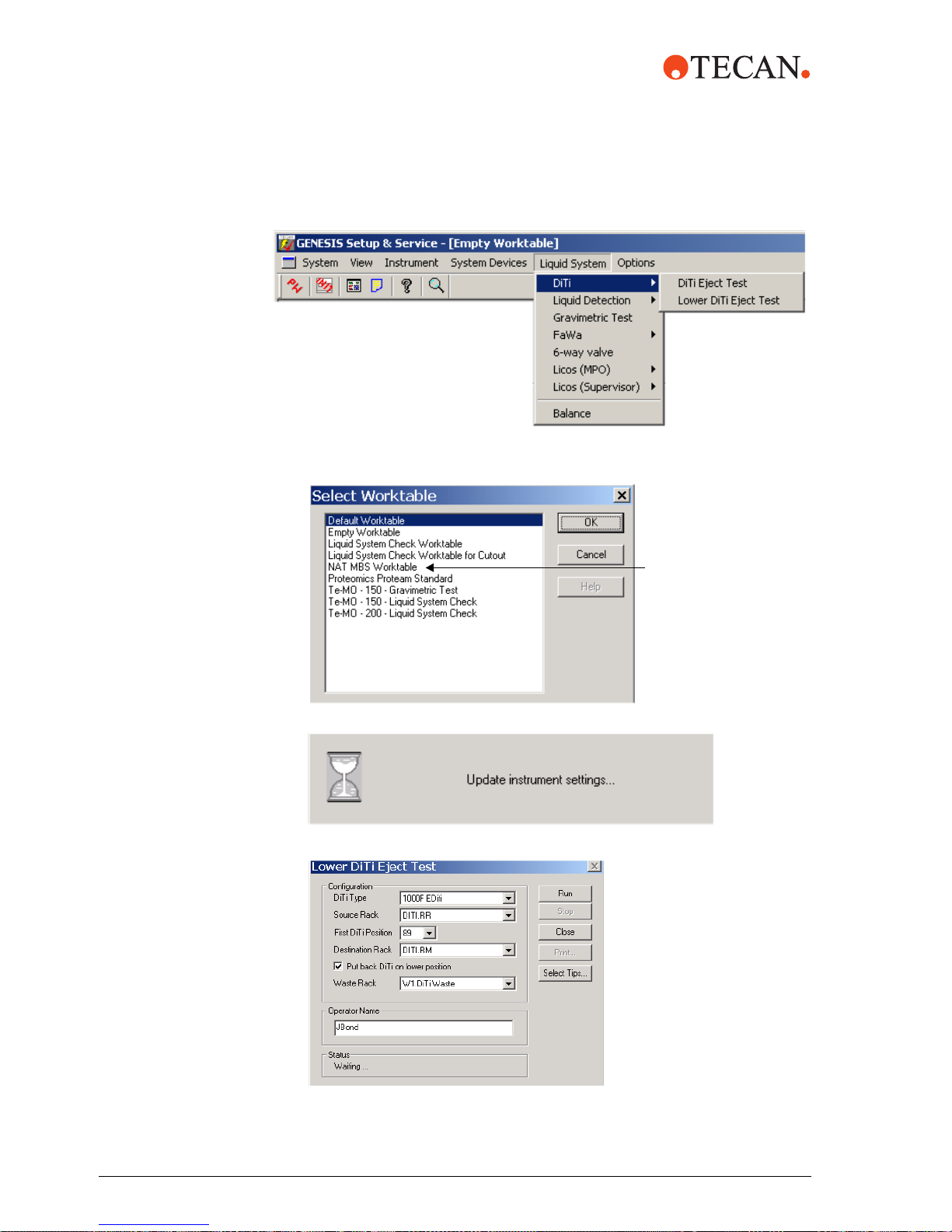
3 Select DiTi from the Liquid System submenu, then select Lower DiTi Eject.
4 From the Select Worktable screen, select NAT MBS Worktable and then
<OK>.
5 The prompt Update instrument settings is displayed.
6 Next, the Lower DiTi Eject Test screen is displayed.
NAT MBS
Worktable
44 m1000™ Operating Manual Addendum, 392813, en, V1.1
Page 49

Complete the following fields:
Field Selection
DiTi Type Enter 1000F EDiTi
Source Rack DiTi.RR
First DiTi Position Enter 89 for the first position to find DiTis
Destination Rack Enter DiTi.RM
Put back DiTi on lower position
Waste Rack Select W1.DiTiWaste
Operator Name Enter operator name
9
7 Place a DiTi rack with an empty DiTi tray in the 1000 µL DiTi.RM position and
a DiTi rack with a full DiTi tray in the 1000 µL DiTi.RR position.
8 Press Run from the Lower DiTi Eject Test screen to start the test.
9 The status changes to Test running.
10 After the test is complete, the status changes to Test passed or Test failed.
Once the test is finished, select Close.
Pass/Fail Criteria
If the Lower DiTi Eject Test fails:
1 Inspect and clean the DiTi cones. Refer to the m1000™ Operation Manual,
Section 7.3.2.
2 Check the DiTi adapter. Refer to the m1000™ Operation Manual, Section
7.3.2.
3 Repeat the Lower DiTi eject. If the test fails again, contact your local Abbott
representative.
m1000™ Operating Manual Addendum, 392813, en, V1.1 45
Page 50

PosID Test This test checks the proper function of the PosID barcode scanner.
During the test a reference read of barcode labels is executed, which is compared
to consecutive reading processes and errors are detected.
ATTENTION
To run the PosID Test, at least two carriers or racks, such as the sample racks and
reagent carriers, must be on the worktable. The carriers must be equipped with
correctly placed barcode labels.
1 Start the GENESIS Setup & Service software by clicking on the
TECAN icon.
2 From the GENESIS Setup & Service main screen, select System Devices
from the menu bar.
3 Select PosID from the System Devices menu. Select Test from the PosID
submenu.
4 The PosID2 Test Configuration screen opens.
46 m1000™ Operating Manual Addendum, 392813, en, V1.1
Page 51

Complete the following fields:
Field Selection
Number of cycles Select 5
Grid Positions Select 1 to 41
Read carrier
Read User ID 9
Operator Enter Operator name
9
5 Place the carriers and racks on the worktable.
Place two sample racks on grids 4 and 5, with multiple barcoded containers
(sample tubes). Face the barcodes to the right side of the sample racks.
Place one reagent carrier trough with barcoded reagent troughs on grid 20.
Place two 1.5 ml output carriers on grids 38 and 39.
6 Select Run to start the test. The PosID2 Test Results window is displayed.
m1000™ Operating Manual Addendum, 392813, en, V1.1 47
7 Select Start to begin the procedure.
8 The PosID2 Test Results window is displayed. During the test, the values in
the PosID2 Test Results window are continuously updated.
Page 52

9 When the test is completed, a PosID2 Test passed or PosID2 Test failed
message is displayed.
10 Confirm with <OK>.
11 Next select Close. The PosID2 Test Configuration screen is now displayed.
12 Select Print to print the test results.
13 Select Close to exit
Pass/Fail Criteria
If the PosID Test fails:
1 Check the positions of the barcode labels.
2 Clean the laser beam output window of the PosID. Refer to the m1000™
Operating Manual, Section 7.4.4.
3 Repeat the PosID test. If the test fails again, contact your local Abbott
representative.
The operator is prompted that the LiHa will move to the Home position. Select
<OK>.
48 m1000™ Operating Manual Addendum, 392813, en, V1.1
 Loading...