

Page 1
TECAN
Operating Manual for the
LS Series Scanner
Document Part No.: 30001798
2004-11
Document Revision No.: 1.5
Page 2

Tecan Affiliates and Service Centers
Austria
Tecan Austria GmbH
Untersbergstrasse 1a
A-5082 Grödig / Salzburg
Austria
Tel.: +43 62 46 89 33
Fax: +43 62 46 72 770
Belgium
Tecan Benelux B.V.B.A.
Vaartdijk 55
B-2800 Mechelen
Belgium
Tel.: +32 15 42 13 19
Fax. +32 15 42 16 12
Italy
Tecan Italia S.r.l.
Via F.lli Cervi
Palazzo Bernini
Centro Direzionale Milano2
20090 Segrate (Mi)
Italy
Tel.: +39 02 215 21 28
Fax: +39 02 215 97 441
Spain
Tecan Spain
Sabino de Arana, 32
E-08028 Barcelona
Spain
Tel.: +34 93 490 01 74
Fax: +34 94 411 24 07
United Kingdom
Tecan UK
Theale Court
11-13 High Street
Theale
UK-Reading RG7 5AH
United Kingdom
Tel.: +44 11 89 300 300
Fax: +44 11 89 305 671
Austria
Tecan Sales International GmbH
Untersbergstrasse 1a
A-5082 Grödig / Salzburg
Austria
Tel.: +43 62 46 89 33
Fax: +43 62 46 72 770
France
Tecan France26 Avenue Tony
Garnier
69007 LYON
France
Tel.: +33 47 27 60 480
Fax: + 33 47 27 60 499
Japan
Tecan Japan Co. Ltd
Meiji Seimei Fuchu Building 10F
1-40 Miyamachi
Fuchu City, Tokyo
Japan
Tel.: +81 42 334 88 55
Fax: +81 42 334 04 01
Sweden
Tecan Nordic AB
Box 208, SE-431 23
Mölndal
Sweden
Tel: +46 31 75 44 000
Fax: +46 31 75 44 010
USA
Tecan US
P.O. Box 13953
Research Triangle Park,
NC 27709
USA
Tel.: +1 919 361 5200
Fax: +1 919 361 5201
Asia
Tecan Asia (Pte) Ltd.
80, Marine Parade #13-04
Singapore 449269
Singapore
Tel.: +65 44 41 886
Fax: +65 44 41 836
Germany
Tecan Deutschland GmbH
Theodor-Strom-Straße 17
D-74564 Crailsheim
Germany
Tel.: +49 79 51 94 170
Fax: +49 79 51 50 38
Netherlands
Tecan Benelux B.V.B.A.
Industrieweg 30
NL-4283 Giessen
Netherlands
Tel.: +31 018 34 48 17 4
Fax: +31 018 34 48 06 7
Switzerland
Tecan Sales Switzerland AG
Seestrasse 103
CH-8708 Männedorf
Switzerland
Tel: +41 922 8 922
Fax: +41 922 8 923
2 Operating Manual for the LS Series Scanner No. 30001798 Rev. No. 1.5 2004-11
Page 3

WARNING
CAREFULLY READ AND FOLLOW THE INSTRUCTIONS PROVIDED IN
Notice
Every effort has been made to avoid errors in text and diagrams, however, Tecan
Austria GmbH assumes no responsibility for any errors which may appear in this
publication.
It is the policy of Tecan Austria GmbH to improve products as new techniques
and components become available. Tecan Austria GmbH therefore reserves
the right to change specifications at any time.
We would appreciate any comments on this publication.
Tecan Austria GmbH
Untersbergstraße 1A
A-5082 Grödig/Salzburg
AUSTRIA / EUROPE
Telephone: 0043 (0) 6246 8933
FAX: 0043 (0) 6246 72770
E-mail: office.austria@tecan.com
THIS DOCUMENT BEFORE OPERATING THE INSTRUMENT.
Copyright Information
The contents of this document are the property of Tecan Austria GmbH and are
not to be copied, reproduced, or transferred to another person or persons without
prior written permission.
Copyright © Tecan Austria GmbH,
All rights reserved.
Printed in Austria
Declaration for EU Certificate
See the back of this document.
About the Instructions for Use
This publication is intended as Instructions for Use for the LS Series Scanner
instruments, which are designed to detect highly quantitative fluorescence
images that have been read from microarray slides or other compatible sample
formats.
This document provides information about:
• Installing the instrument
• Operating the instrument
• Cleaning and maintenance routines
2004-11 Operating Manual for the LS Series Scanner No. 30001798 Rev. No. 1.5 3
Page 4

Warnings, Cautions and Notes
There are four types of notices used in this publication. These notices highlight
important information or warn the user of a potentially dangerous situation.
The notices appear below:
Note
Gives helpful information.
Caution
Indicates a possibility of instrument damage or data loss if instructions
are not followed.
WARNING
INDICATES THE POSSIBILITY OF SEVERE PERSONAL INJURY, LOSS
OF LIFE OR EQUIPMENT DAMAGE IF THE INSTRUCTIONS ARE NOT
FOLLOWED.
WARNING
INDICATES LASER. DO NOT STARE INTO THE BEAM!
WARNING
INDICATES THE POSSIBLE PRESENCE OF BIOLOGICALLY
HAZARDOUS MATERIAL. PROPER LABORATORY SAFETY
PRECAUTIONS MUST BE OBSERVED.
4 Operating Manual for the LS Series Scanner No. 30001798 Rev. No. 1.5 2004-11
Page 5

Table of Contents
1 Safety
1.1 Instrument Safety .......................................................................... 1-1
2 General
2.1 Instrument Features ...................................................................... 2-1
2.1.1 Samples........................................................................................... 2-2
2.1.2 Modes of operation.......................................................................... 2-3
2.1.3 Automation friendliness................................................................... 2-4
2.1.4 Integrated Image Analysis Software Array Pro................................ 2-4
3 Installation
3.1 Unpacking & Inspection................................................................ 3-1
3.2 Remove Transport Lock ............................................................... 3-7
3.3 Filter Installation............................................................................ 3-8
3.4 Power Requirements..................................................................... 3-9
4 Technical Description
4.1 Optical System............................................................................... 4-1
4.2 Autofocus....................................................................................... 4-3
4.3 Data Processing ............................................................................ 4-3
5 Operation
5.1 General Operating Features ......................................................... 5-2
5.1.1 Instrument Start Up ......................................................................... 5-2
5.1.2 Instrument Power On....................................................................... 5-2
5.1.3 Connect to Instrument..................................................................... 5-3
5.1.4 Finish a Measurement Session....................................................... 5-3
5.2 Insert Slide(s) into Slide Adapter ................................................. 5-4
6 LSServer, Scanner Shell and Download
6.1 Introduction.................................................................................... 6-1
6.1.1 Overview.......................................................................................... 6-1
6.1.2 Hardware Requirements.................................................................. 6-1
6.1.3 Software Requirements...................................................................6-2
6.1.4 Software Installation Procedure....................................................... 6-2
6.2 Tecan LS Scanner Interface ......................................................... 6-4
6.2.1 Overview.......................................................................................... 6-4
6.2.2 Starting LS Scanner Interface ......................................................... 6-4
6.3 LSServer......................................................................................... 6-6
6.3.1 Starting the First Time..................................................................... 6-6
6.3.2 Measurement Control......................................................................6-6
6.3.3 File Types used in LSServer ........................................................... 6-9
6.3.4 Measurement................................................................................. 6-11
6.3.5 Instrument...................................................................................... 6-26
2004-11 Operating Manual for the LS Series Scanner No. 30001798 Rev. No. 1.5 5
Page 6

6.3.6 Measurement Parameter................................................................ 6-28
6.3.7 Excitation Angle Tab ......................................................................6-49
6.3.8 Settings .......................................................................................... 6-54
6.3.9 Slide Adapter Format .....................................................................6-62
6.3.10 Slides to Process............................................................................6-62
6.4 LS Scanner Shell..........................................................................6-64
6.4.1 General ..........................................................................................6-64
6.4.2 Starting Scanner Shell....................................................................6-64
6.4.3 Window Elements...........................................................................6-64
6.4.4 File types used in Scanner Shell....................................................6-66
6.4.5 Scanner Shell Menus.....................................................................6-68
6.4.6 Service Menu .................................................................................6-75
6.4.7 Stacker Setup - Twister..................................................................6-89
6.4.8 Scanner Shell Wizards...................................................................6-91
6.4.9 The Transport Lock Wizard............................................................6-92
6.4.10 The Transport Unlock Wizard.........................................................6-95
6.5 LSDownload................................................................................6-101
6.5.1 Starting LSDownload....................................................................6-101
6.5.2 LSDownload Menus.....................................................................6-102
7 Instrument Features
7.1 Specifications.................................................................................7-1
7.1.1 Lasers ..............................................................................................7-4
7.1.2 Optional Barcode Scanner...............................................................7-4
7.1.3 Reproduction of labels placed on the instrument.............................7-5
8 Cleaning & Maintenance
8.1 Introduction ....................................................................................8-1
8.2 Liquid Spills....................................................................................8-1
8.3 Replacing the Fuse ........................................................................8-2
8.4 Remote Control and Data Exchange ............................................8-3
8.4.1 FTP up / download...........................................................................8-3
8.4.2 Working with pcAnywhere:...............................................................8-3
8.4.3 Working with CITRIX web conferencing manager:...........................8-5
8.5 Instrument Disinfection .................................................................8-6
8.5.1 Disinfection Solutions.......................................................................8-6
8.6 Disinfection Procedure..................................................................8-7
8.7 Disinfection Certificate ..................................................................8-7
8.8 Disposal of Instrument ..................................................................8-8
8.8.1 Disposal of Packing Material............................................................8-8
8.8.2 Disposal of Operating Material.........................................................8-8
Index
6 Operating Manual for the LS Series Scanner No. 30001798 Rev. No. 1.5 2004-11
Page 7

1. Safety
1. Safety
1.1 Instrument Safety
1. Always follow basic safety precautions when using this product to reduce the risk of
injury, fire, or electrical shock.
2. Read and understand all information in the Operating manual. Failure to read,
understand, and follow the instructions in the manual may result in damage to the
product, injury to operating personnel or poor instrument performance.
3. Observe all WARNING and CAUTION statements in the manual.
4. Never open the LS SERIES SCANNER while the instrument is plugged into a power
source. The instrument contains class 2, 3a and 3b lasers inside.
5. Never force a slide or another sample into the instrument.
6. LS SERIES SCANNERS are intended for laboratory research use only. Observe
proper laboratory safety precautions, such as wearing protective clothing and using
approved laboratory safety procedures.
2004-11 Operating Manual for the LS Series Scanner No. 30001798 Rev. No. 1.5 1-1
Page 8

Page 9

2. General
2. General
2.1 Instrument Features
The LS SERIES SCANNERS are laser-scanning instruments designed to detect
highly quantitative fluorescence images. The scanners are designed to read
microarray slides as well as other customer specific sample formats. They have
exceptional flexibility with respect to sample formats and measurement modes.
They can read samples up to the size of microplates as well as thick samples like
gels or, for instance, liquid cells. They can read both in confocal and in nonconfocal mode and a selection of up to 4 excitation wavelengths (lasers) and an
almost unlimited number (28) of emission wavelengths or emission filters.
Automation friendliness is another key feature of the LS SERIES SCANNERS.
The design allows the use of standard microplate equipment to load very high
numbers of slides automatically. For instance, with a Connect, up to 200 slides or
50 microplates can be loaded and processed automatically within one run.
2004-11 Operating Manual for the LS Series Scanner No. 30001798 Rev. No. 1.5 2-1
Page 10
2. General
2.1.1 Samples
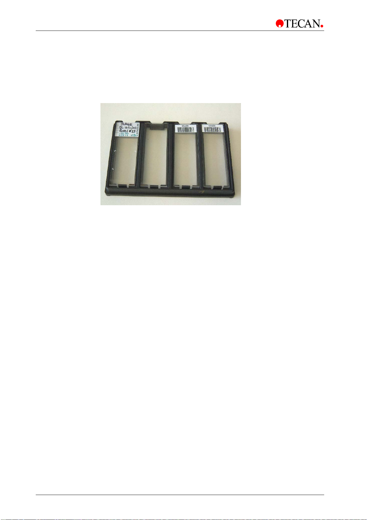
Slide adapters
Its special microplate/slide adapters accommodate 4 slides at once and loading is
easily automated with standard microplate equipment.
Other formats
Due to its flexible design, other sample formats can be measured as well.
The software allows special formats to be defined and special scanning areas to
be processed. Due to an exceptionally high working distance of 6.5 mm,
‘thick’ samples, well structures, samples within a liquid cell or even gels can be
measured. An automatic autofocus system is able to bring all of these samples
into the proper focal plane. If you are in doubt whether a special sample format
can be measured with the LS SERIES SCANNERS, please contact a Tecan
representative.
2-2 Operating Manual for the LS Series Scanner No. 30001798 Rev. No. 1.5 2004-11
Page 11

2. General
2.1.2 Modes of operation
Confocal or non-confocal
The LS SERIES SCANNERS are equipped with 3 different user selectable
pinholes for selection of the appropriate depth of focus. The smaller the pinhole
the higher is the confocality of the optical system and the shorter the depth of
field. A small pinhole typically gives a better signal to background ratio, because
all background contributions from outside the focal plane, e.g. the glass material
or the backside of the slide are rejected. However for bulkier samples or samples
with an uneven or a slightly bent surface confocality can result in lower signals or
in a poor reproducibility. Here a larger pinhole is more appropriate. That’s why the
LS SERIES SCANNERS offer the choice. Just choose the degree of confocality
that is best suited for the samples.
Excitation wavelengths
• The LS Scanner can be equipped with up to 4lasers.
• Every Scanner has a HeNe laser with 633nm.
• Lasers with the wavelengths 488nm, 532nm and 694 nm are optional.
Emission wavelengths
Filters are located in special filter slides. The standard configuration comes with
one filter for each excitation wavelength or laser respectively.
Additional filters can be added into the filter slides. The filter slides can be
exchanged by the user. The ‘identity’ of each filter slide is automatically detected
by the instrument when it is inserted into the slot.
Dual scanning
In order to increase the overall scan speed, two colors can be measured
simultaneously with a dual channel instrument. A calibration algorithm takes care
of the crosstalk between the two colors and corrects for it online. If you have
purchased a single channel instrument, or if the wavelengths are too close to
each other, the instrument can measure the two colors sequentially as well.
Resolution
The standard resolution is 10 µm.
For larger sample features there is the option to scan with 20 µm or 40 µm thus
both increasing scan speed and decreasing the amount of data.
Smaller structures can be better resolved with 6 µm or 4 µm pixel resolution.
Scan widths for a single path scan are 22 mm for 10 µm, 20 µm and 40 µm, 6 µm
pixels and 15 mm for 4 µm pixels.
Optimize sensitivity
For smaller scanning areas, there is a user selectable option to increase
sensitivity without changing the scan time.
Another way to increase sensitivity is to scan transparent slides upside down.
The reason is because surface bound molecules emit the greater part of their
fluorescence into the medium with higher refractive index (e.g. glass).
2004-11 Operating Manual for the LS Series Scanner No. 30001798 Rev. No. 1.5 2-3
Page 12
2. General
2.1.3 Automation friendliness
Because the LS SERIES SCANNERS are designed to interface with microplate
technology, they are very well prepared for automation using existing microplate
equipment. Four slides can be loaded in an adapter with the outer dimensions of
a microplate. The number of slides is limited only by the stacking capacity of the
external microplate device.
2.1.4 Integrated Image Analysis Software Array Pro
The LS SERIES SCANNERS come with an integrated array analysis software
package.
Caution
If the instructions given in this manual are not correctly carried out, the
instrument May either become damaged or May no Longer be Able to
perform Its Procedures correctly and the Accuracy of the instrument
can no longer be guaranteed.
Note
In order to obtain reliable results it is strongly recommended to place
reference spots onto your sample for quality control. These spots should
represent every dye of your experiment and it is recommended that they
are distributed in a non symmetric pattern across your sample. It is also
recommended to place ‘blank’ spots onto your arrays in order to check
for the variation of the background in your experiment.
2-4 Operating Manual for the LS Series Scanner No. 30001798 Rev. No. 1.5 2004-11
Page 13
3. Installation
3. Installation
3.1 Unpacking & Inspection
The delivered container includes the following:
• Instrument
• PC
• PC Monitor
• Manual
• Software: Driver LS Series Scanner (1 CD-ROM)
• Cables (RS232 cable and 1 interface cable)
• Slide Adapters
• Filter Slide
• Reference slides (histological section of mouse; spots)
• Array Pro Software
• Hardware Key Array Pro SW
• Installation CD Array Pro SW
• Array Pro User Manual
• Scattered light glass slide
• Filter Slide for Calibration
• 2 Filter Slides
Caution
Before the instrument is installed and switched on, it should be left to
stand for at least three hours, so there is no possibility of condensation
causing a short circuit.
2004-11 Operating Manual for the LS Series Scanner No. 30001798 Rev. No. 1.5 3-1
Page 14
3. Installation
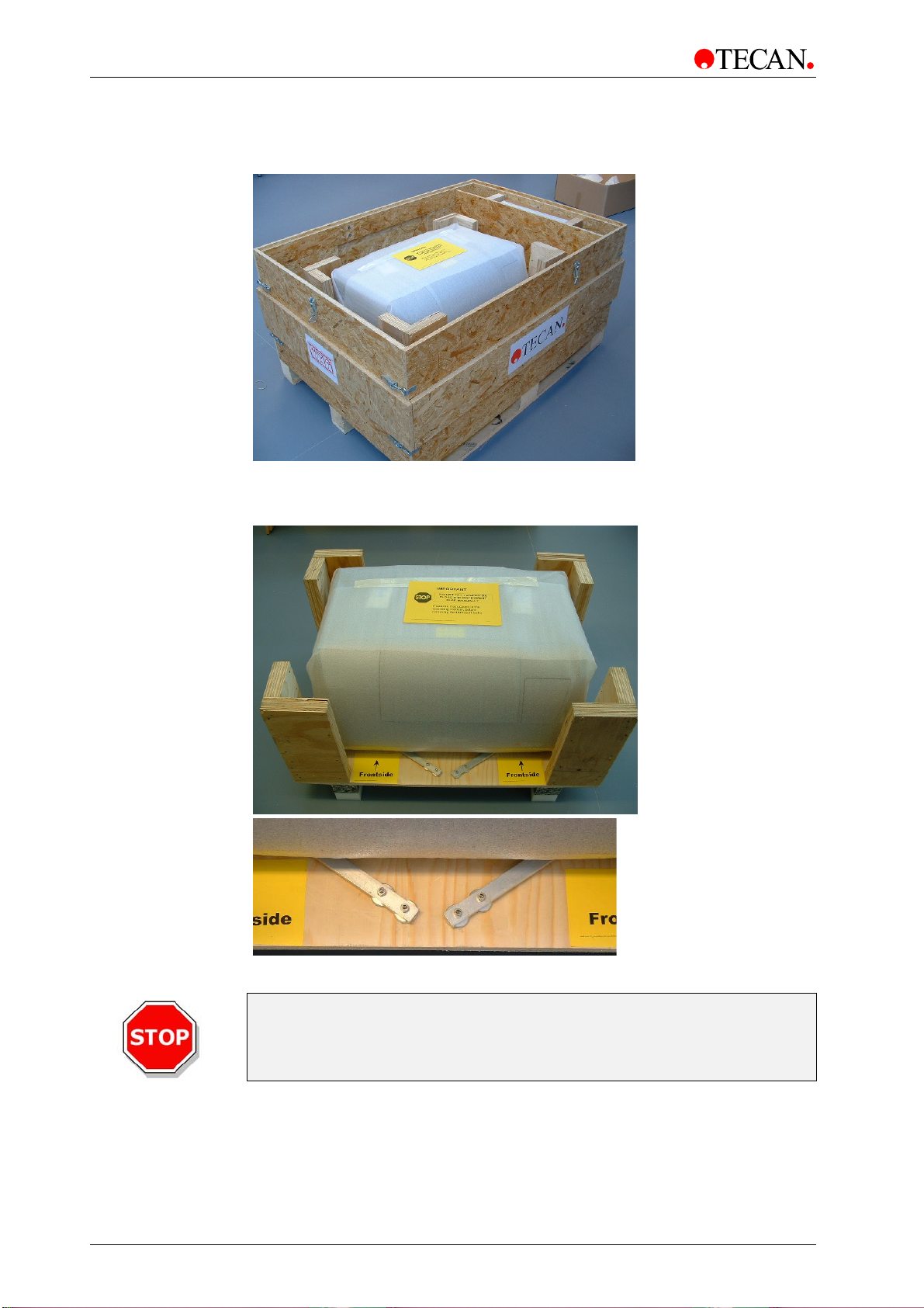
Visually inspect the container for damage before it is opened.
Report any damage immediately.
Select a location to place the instrument that is flat, level, vibration free, away
from direct sunlight, and free from dust, solvents and acid vapors. Allow at least
10 cm between the instrument and the wall or any other equipment.
Remove transportation locks.
Caution
The LS Series Scanners are precision instruments
and are very heavy. At least two people
3-2 Operating Manual for the LS Series Scanner No. 30001798 Rev. No. 1.5 2004-11
must carefully lift the instrument from the box.
Page 15
3. Installation
Visually inspect the instrument for loose, bent or broken parts.
Report any damage immediately.
Compare the serial number on the rear panel of the instrument with the serial
number on the packing slip.
Report any discrepancy immediately.
Check the instrument accessories against the packing list.
Save packing materials and transport locks (see next section) for further
transportation purposes.
Caution
Do not try to open or close
the instrument flap manually.
Ensure that the flap cannot be accidentally hit when it is opened automatically.
Ensure that the main switch and the main cable can be reached at all times
and are in no way obstructed.
Caution
The maximum load for the top of the housing
of an LS Series Scanner is 3 kg.
Caution
Keep fingers away from the flap when it is closing
or when a scan has been started.
2004-11 Operating Manual for the LS Series Scanner No. 30001798 Rev. No. 1.5 3-3
Page 16
3. Installation
Place the PC with monitor, keyboard and mouse next to the instrument.
Ensure the computer is switched OFF and the instrument's main power switch on
the back panel of the instrument is in the OFF position.
Check the voltage specifications on the computer and ensure that the voltage
supplied to the computer is correct according to the specification input range
selector (red button) at the power supply.
Caution
Check voltage specification on the computer BEFORE switching ON. If
computer is switched ON with the incorrect voltage supply it will be
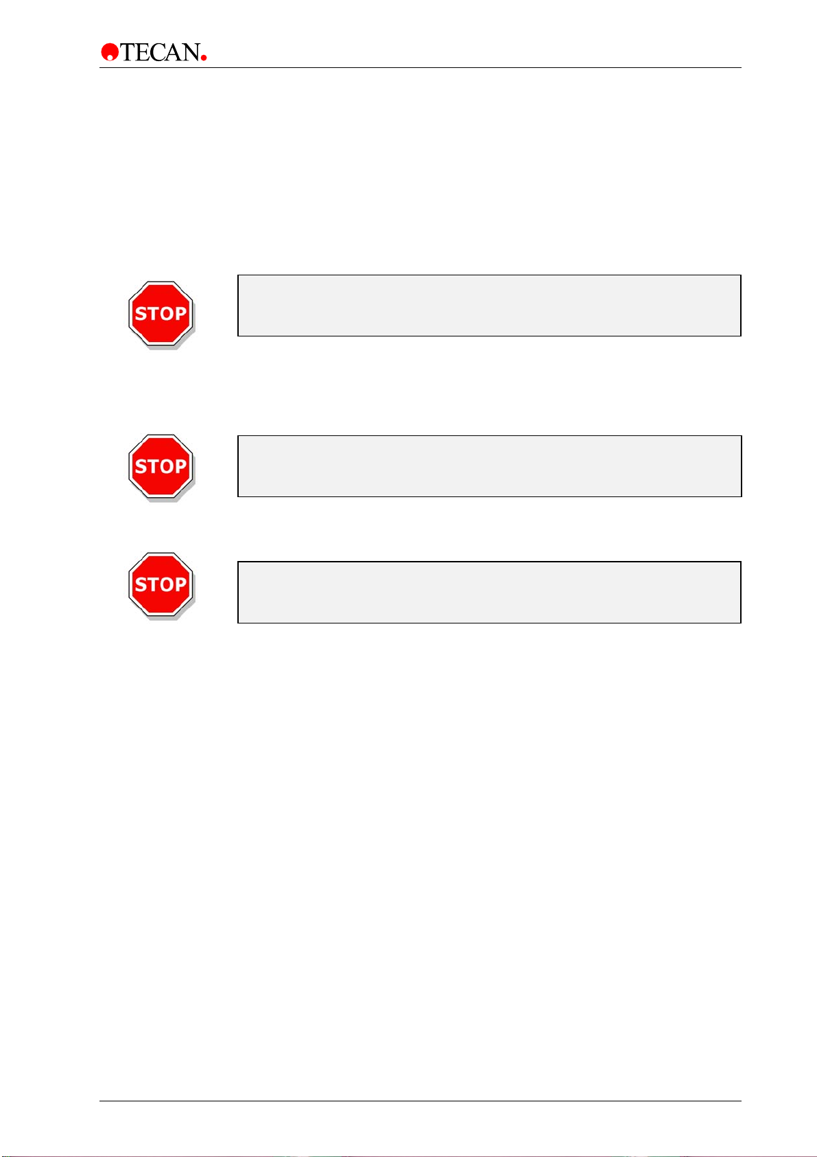
Connect the computer to the instrument with the delivered RS 232 interface
cable.
Connect the computer to the instrument with the delivered special interface cable.
The pictures below show the connection of the interface cables
to the rear of the instrument:
damaged.
Data cable to
connector box
RS232 to
computer
3-4 Operating Manual for the LS Series Scanner No. 30001798 Rev. No. 1.5 2004-11
Page 17
RS232 to
instrument
3. Installation
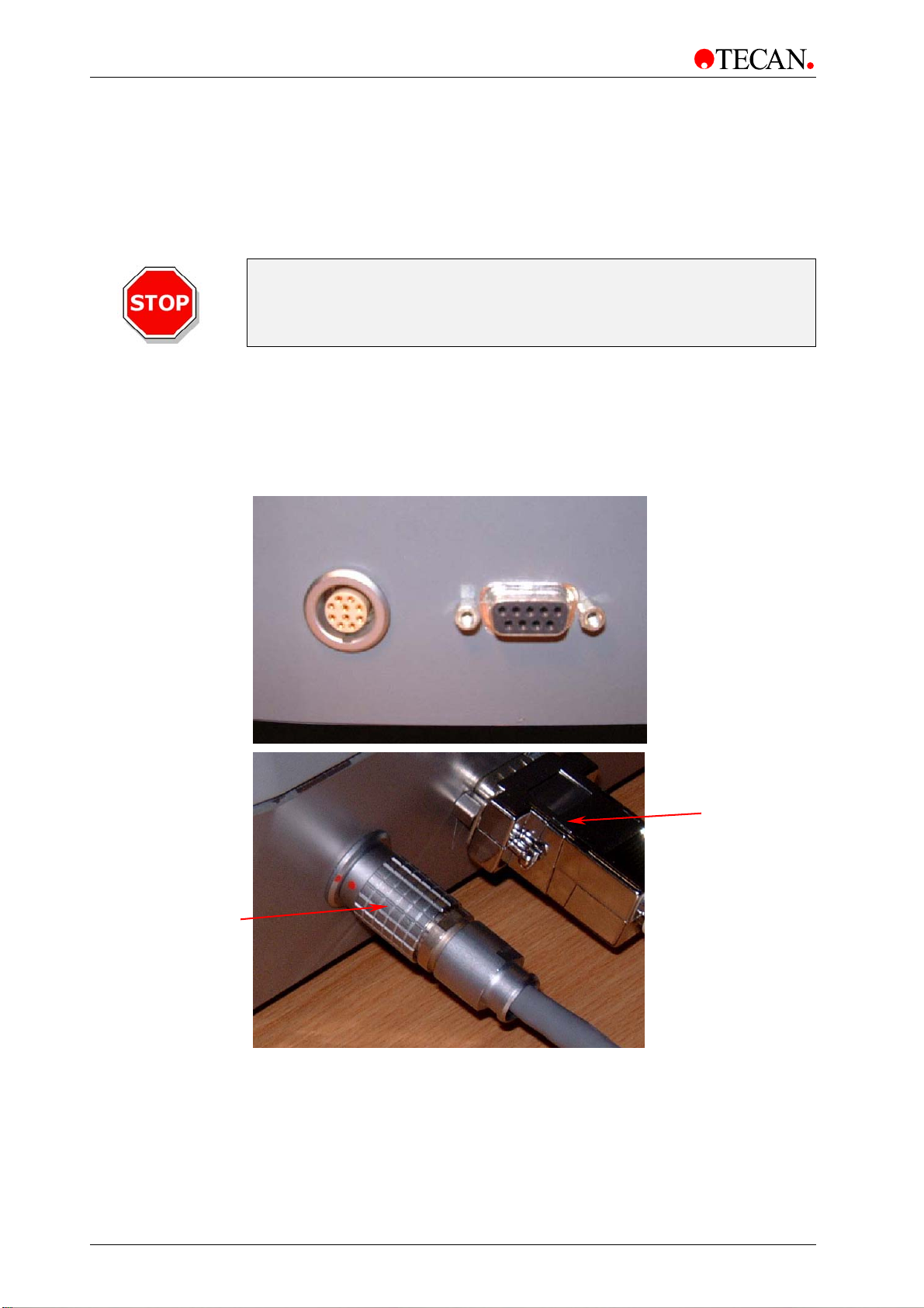
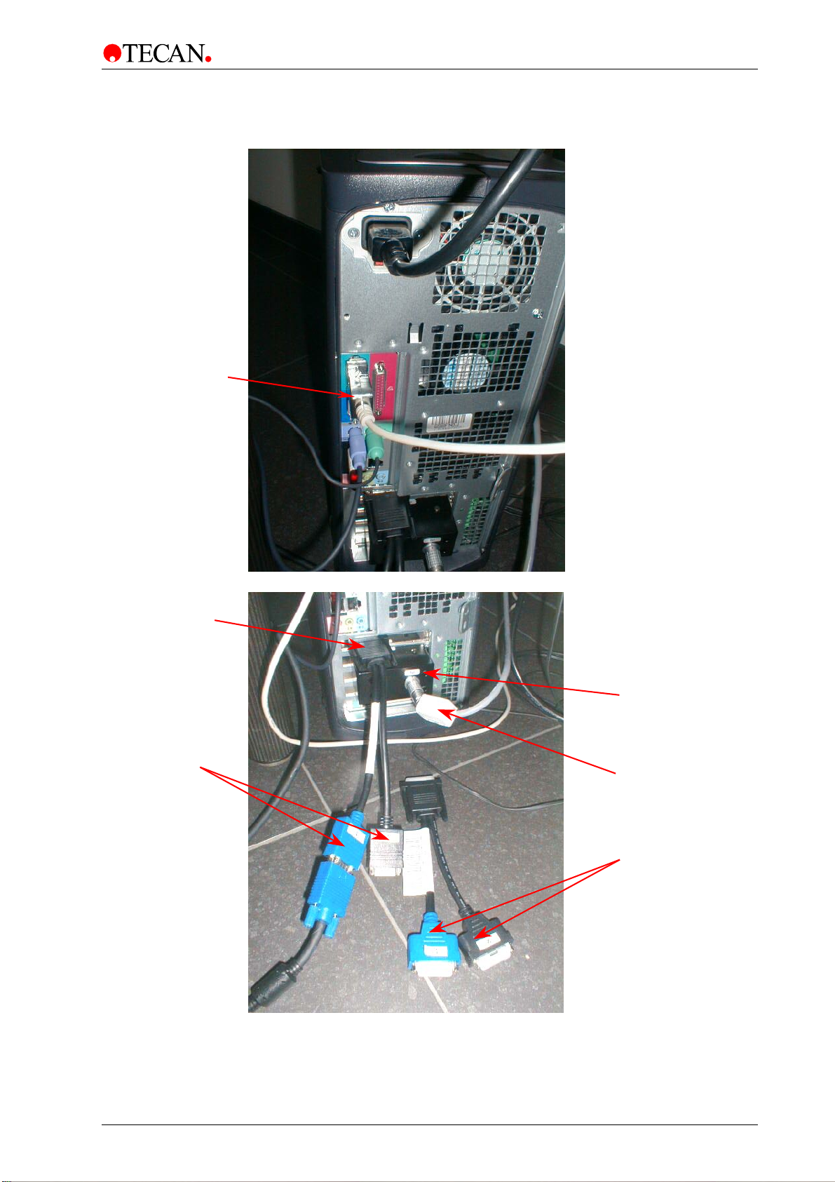
The pictures below show the connection of the interface cables
to the back of the computer:
Connection
for monitor
cables
Digital
monitor
cables
Connector
box
Data cable to
instrument
Analog
monitor
2004-11 Operating Manual for the LS Series Scanner No. 30001798 Rev. No. 1.5 3-5
Page 18
3. Installation
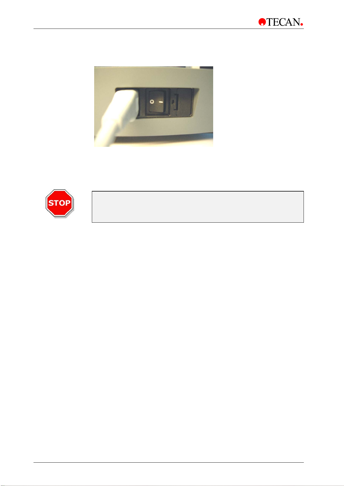
Insert the power cable (with protective ground connection) into the main power
socket in the back panel of the instrument.
All connected devices must be approved and listed with regulations EN 60950,
UL 1950 or CSA C22.2 No. 950 for Data Processing Devices.
Switch the computer ON.
Switch the instrument ON using the switch on the back panel of the instrument.
Caution
Keep fingers away from the flap when it is closing
or when a scan has been started.
3-6 Operating Manual for the LS Series Scanner No. 30001798 Rev. No. 1.5 2004-11
Page 19
3. Installation
3.2 Remove Transport Lock
Start LS Scanner Shell.
Select Instrument and click Connect.
A message appears that instrument is locked.
For more information on removing the transport lock see chapter 6.4.10 The
Transport Unlock Wizard.
Do not try to open or close
Save packing materials and transport locks
for further transportation purposes. The LS series scanners must be
and the transport locks must be installed.
the instrument flap manually.
shipped with the original packing
Caution
Caution
Caution
Before Transportation
Place the instrument carefully in the indicated orientation before fixing the
transportation locks, otherwise the instrument will become damaged.
2004-11 Operating Manual for the LS Series Scanner No. 30001798 Rev. No. 1.5 3-7
Page 20
3. Installation
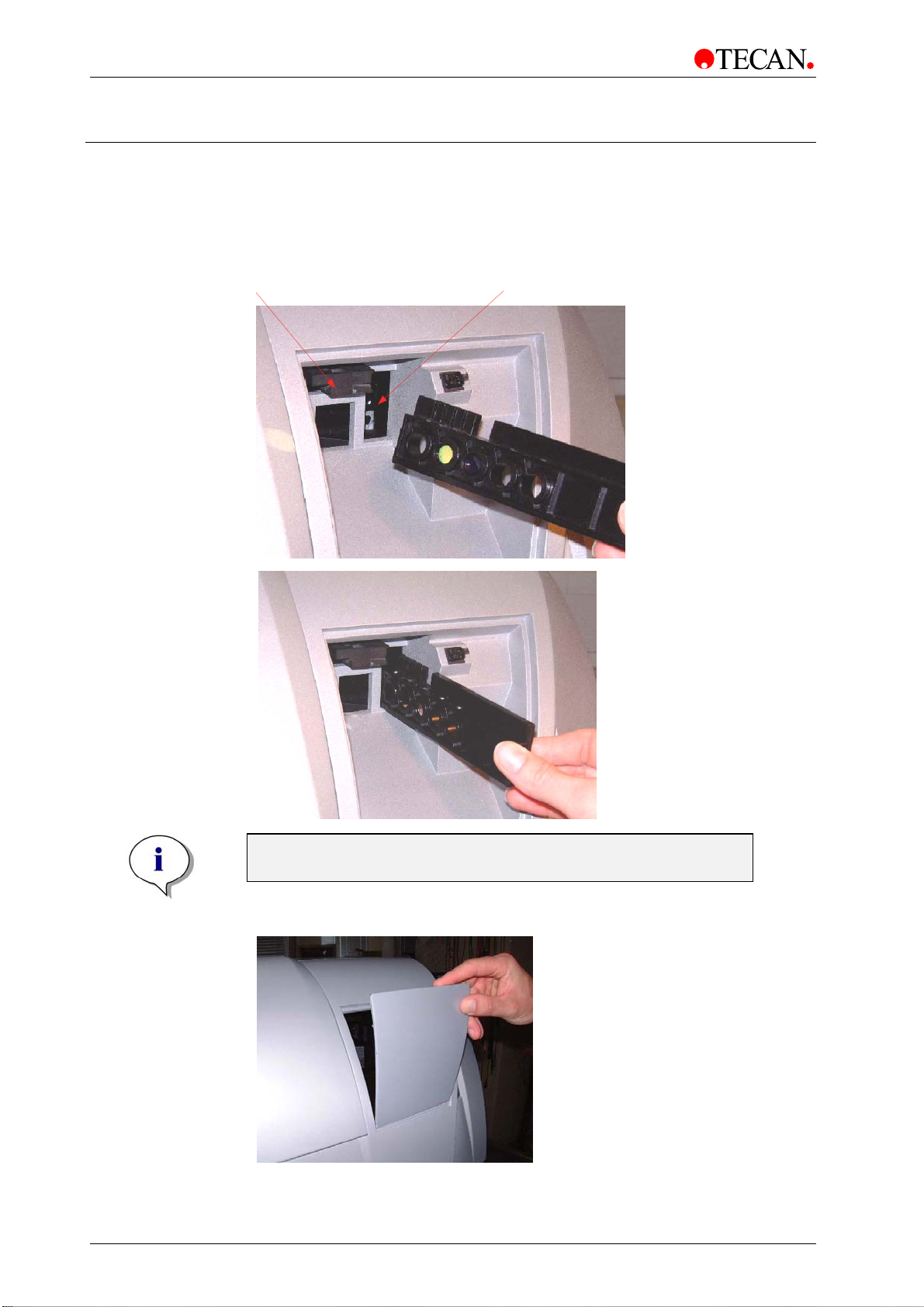
3.3 Filter Installation
Insert the Filter Slides into Filter Channel 1(vertical orientation) and Filter Channel
2 (horizontal orientation) and make sure that the filters are oriented properly, (see
pictures below).
Filter Channel 1 Filter Channel 2
Note
Both filter slides are only necessary in dual channel instruments.
• Close the filter compartment
3-8 Operating Manual for the LS Series Scanner No. 30001798 Rev. No. 1.5 2004-11
Page 21
3. Installation
3.4 Power Requirements
The instrument is auto sensing and it is, therefore, unnecessary to make any
changes to the voltage range.
Check the voltage specifications on the rear panel of the instrument to ensure
that the voltage supplied to the instrument is correct according to the
specification.
The voltage range is 100-120 / 220-240 V.
If the voltage is not correct, please contact your distributor.
Ensure that a fuse of the correct type and rating is fitted.
Fuse = T 2.0 A / 250 V (slow blow) UL recognized
WARNING
RISK OF FIRE!
REPLACE ONLY WITH FUSES
OF THE SAME TYPE AND RATING.
Caution
When installing or uninstalling the instrument ensure that the instrument
and the computer are both switched off and disconnected from the main
power supply before the RS 232 interface cable or the special connector
cable is connected or removed.
Caution
If the instructions given in this manual are not correctly carried out, the
instrument May either become damaged or May no Longer be Able to
perform Its Procedures correctly and the Accuracy of the instrument
can no longer be guaranteed.
2004-11 Operating Manual for the LS Series Scanner No. 30001798 Rev. No. 1.5 3-9
Page 22

Page 23
4. Technical Description
4. Technical Description
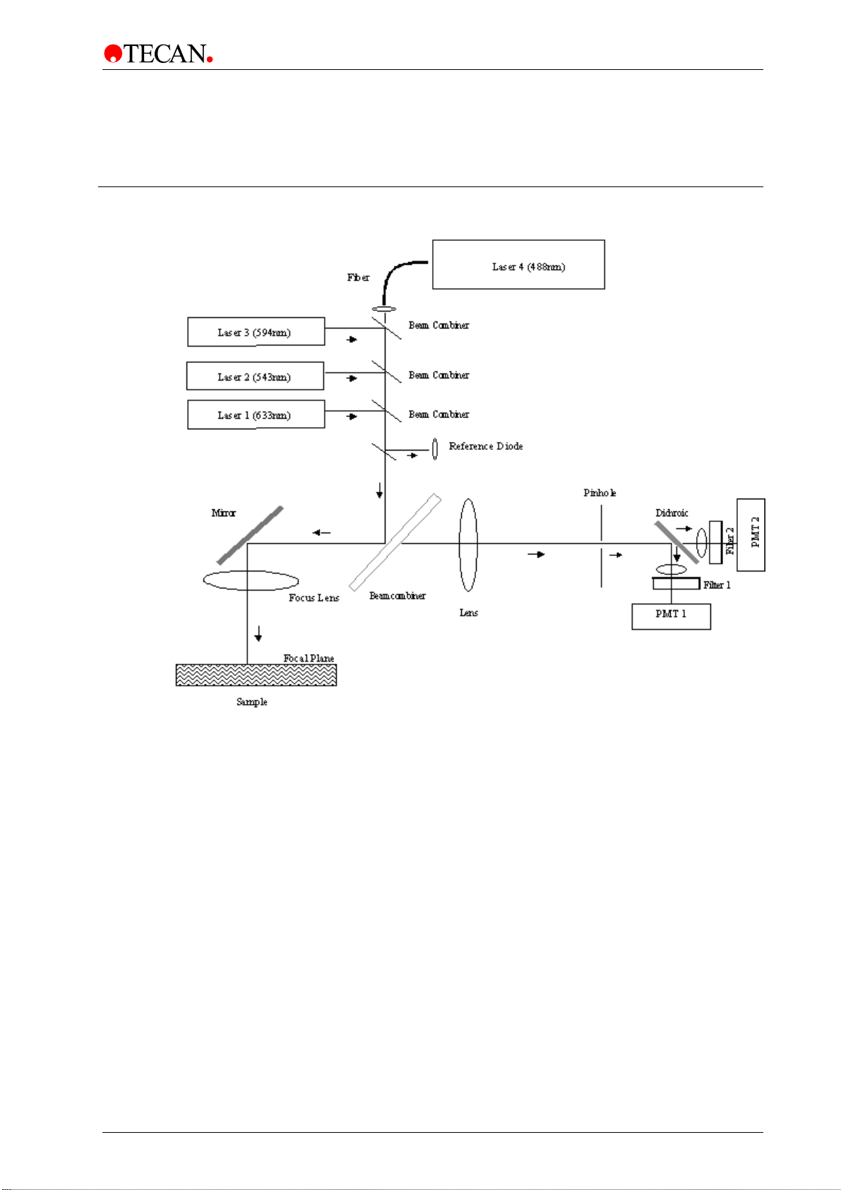
4.1 Optical System
Figure 4.1
For excitation of fluorescence signals up to 4 lasers are installed. The lasers for
633 nm, and 594 nm are Helium Neon lasers; the lasers for 488 nm and 532nm
are solid state lasers. Both of these laser types have excellent beam quality and
stability.
Laser beams are combined with dichroic elements to enter the scanner in a
collinear alignment.
2004-11 Operating Manual for the LS Series Scanner No. 30001798 Rev. No. 1.5 4-1
Page 24
4. Technical Description
Scanning is done in a first direction with the excitation beam. This very fast
scanning mechanism scans 40 lines per second. The overall scanning speed and
scanning time in this direction is independent from both pixel resolution and scan
width. The second scanning dimension is achieved by moving the sample in a
perpendicular direction. This movement is exactly synchronized with the first scan
axis to create a 2-dimensional fluorescence image. For example at 10 µm
resolution 4 mm are scanned within 10 s ((4 mm / 40 lines / s) * (100 lines / mm
10 µm pixel size)
) = 10 s). For this second direction the scanning speed is reciprocal
to the resolution and the overall scanning time depends linearly on the scan
length.
Fluorescence light is collected with a high aperture lens with exceptional working
distance (up to 6.5 mm). This long working distance is the key for the ability to
measure flexible sample formats other than slides.
A second lens refocuses the collected light onto a pinhole, thus creating a
confocal detection scheme.
Three pinholes of different sizes are mounted on an automatic slide carrier. The
smaller the pinhole, the lower the focal depth of the detected volume. The larger
pinholes typically create images with a slightly lower signal to background ratio
but offer the choice to measure bulky samples or uneven surfaces as well.
Behind the pinhole the fluorescence light passes through a bandpass filter that
rejects light of the excitation wavelength and all other spectral contributions that
are not within the detection bandwidth of the selected filter. Filters are arranged in
filter slides that can hold up to four different filters. Each filter slide has five
positions, but one of them has to stay open for autofocus purposes.
Filter slides can easily be removed or exchanged; up to 8 different slides can be
automatically identified by the instrument firmware when they are inserted in the
filter slots.
In the dual channel instrument a dichroic beamsplitter separates the two emission
wavelengths of the first and the second dye (e.g. Cy3 and Cy5) and lets them
pass trough two different emission filters and to two different photomultiplier tubes
(PMT’s). The two different filters are located on two different filter slides in that
case.
A reference diode monitors laser power before each measurement.
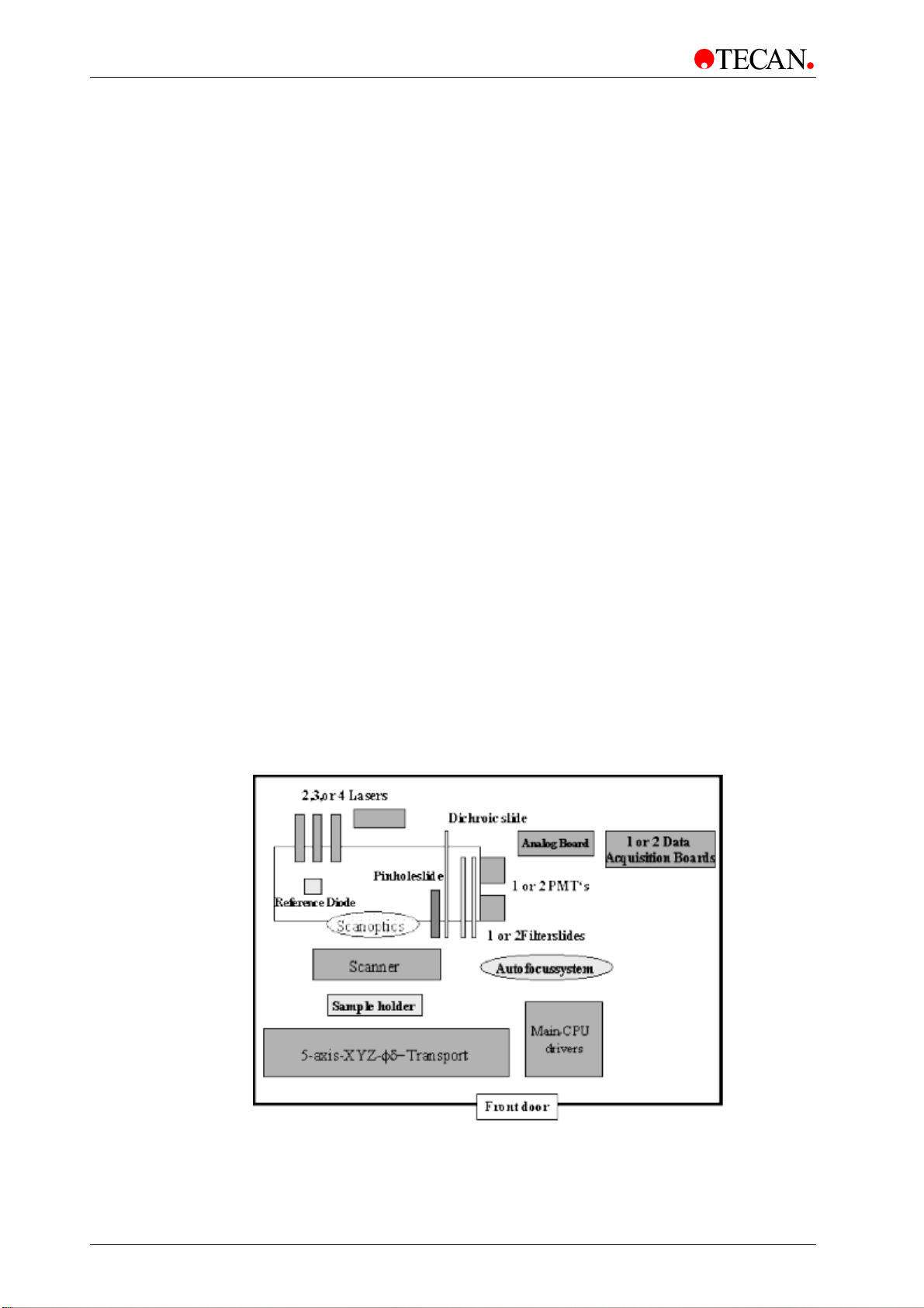
(=
Figure 4.2
4-2 Operating Manual for the LS Series Scanner No. 30001798 Rev. No. 1.5 2004-11
Page 25

4. Technical Description
4.2 Autofocus
A key element for the flexibility of the instrument is the autofocus system. It allows
every sample individually to be adjusted - exactly in the focal plane of the optics.
Because this is done immediately before each scan, out of focus images due to
long term drifts of the optical alignment are not an issue with the LS SERIES
SCANNERS.
Before each scan two z-scans are done across user defined lines in the sample.
This way two short ‘vertical’ images are recorded typically close to both ends of
the slide or the sample. (z-axis is moved instead of x-axis). These z-scan images
are taken to calculate the exact position and the orientation of the sample.
Orientation of the sample is also calculated because slight amounts of tilt could
give poor results with a confocal measurement scheme.
The sample is then brought into the exact focal plane both with regard to z as well
as the two angles of tilt. This process is fully automated. Signals are recorded in
reflection mode and with a dimmed beam (4 orders) to prevent bleaching.
To realize this functionality a high precision 5-axis transport system is
implemented in the LS SERIES SCANNERS. The five axis are: X (scan axis), Y
(moves sample tray between different slides or different areas on larger
samples), Z (brings sample into focal position), ϑ and Φ (correct for angles of tilt
of the sample or tolerances of the adapters). Precisions for the axis’ are in the
range of 1-2µm.
4.3 Data Processing
Further data processing is done by an analog amplifier PCB and fast 16 bit data
acquisition boards. The latter ones are plugged into the PC and connected to the
instrument with a special interface cable.
An internal Main-CPU takes control of all the actuators and data acquisition steps
during scan. It is interfaced with a RS232 cable with the PC.
On the PC the Array Pro software is an integrated package both for instrument
control and for array processing.
2004-11 Operating Manual for the LS Series Scanner No. 30001798 Rev. No. 1.5 4-3
Page 26

Page 27
5. Operation
5. Operation
The LS SERIES SCANNER is operated using personal computer based software
control. The Array Pro Software is used both for instrument control and data
analysis.
This chapter describes the instrument and the instrument control software. It is
intended for a general understanding of instrument parameters and operation.
For details of the data analysis see the corresponding Array Pro software manual.
Suggestions are made on how to optimize the instrument parameters for your
applications.
Every effort has been made to ensure that the instrument will work correctly even
if the default parameters are not appropriate for a particular application
- with an important exception:
When placing a sample into the sample carrier,
always make sure that the correct slide and slide carrier definitions are
Wrong definitions, especially with special samples can lead to damage of
the instrument or the sample.
Caution
selected in the software.
2004-11 Operating Manual for the LS Series Scanner No. 30001798 Rev. No. 1.5 5-1
Page 28
5. Operation
5.1 General Operating Features
The LS Series Scanner has some general behavior and options, which are
independent from particularly selected measurement techniques.
5.1.1 Instrument Start Up
Before the instrument is powered ON, ensure that both of the interface cables are
connected.
Caution
When the serial interface cable
or the special interface cable
is being plugged in or unplugged,
the instrument and the PC should be powered off.
5.1.2 Instrument Power On
When switching the instrument ON, the following actions are induced:
• The filter slides move into the reference position
• The dichroic filter carrier moves into the reference position
• The pinhole carrier moves into the reference position
• The microplate transport moves into the reference position
• The cooling fans start to ventilate
At the beginning of each session the user is requested to choose the lasers to be
used in this session. Only the selected lasers will be switched on. This is done to
increase the lifetime of the lasers.
The lasers need a warm up time of 20 minutes. The instrument is already
functional before that time, but performance according to the
specifications is guaranteed only after the warm up time has elapsed.
Scans can be done before that time.
Note
5-2 Operating Manual for the LS Series Scanner No. 30001798 Rev. No. 1.5 2004-11
Page 29

5. Operation
5.1.3 Connect to Instrument
When the software connects to the instrument, communication is established
between the instrument and the user interface. The instrument is ready for
operation.
5.1.4 Finish a Measurement Session
Disconnect from Instrument
When disconnecting, communication between the instrument and the PC is
terminated.
Please remove the recently measured sample before disconnect.
Instrument Shut Down
Note
Upon shut down, the instrument activity is stopped immediately. Normally, you
should disconnect before shut down. In the rare case of an unexpected hardware
error, immediate instrument shut down will reduce the risk of possible damage.
2004-11 Operating Manual for the LS Series Scanner No. 30001798 Rev. No. 1.5 5-3
Page 30
5. Operation
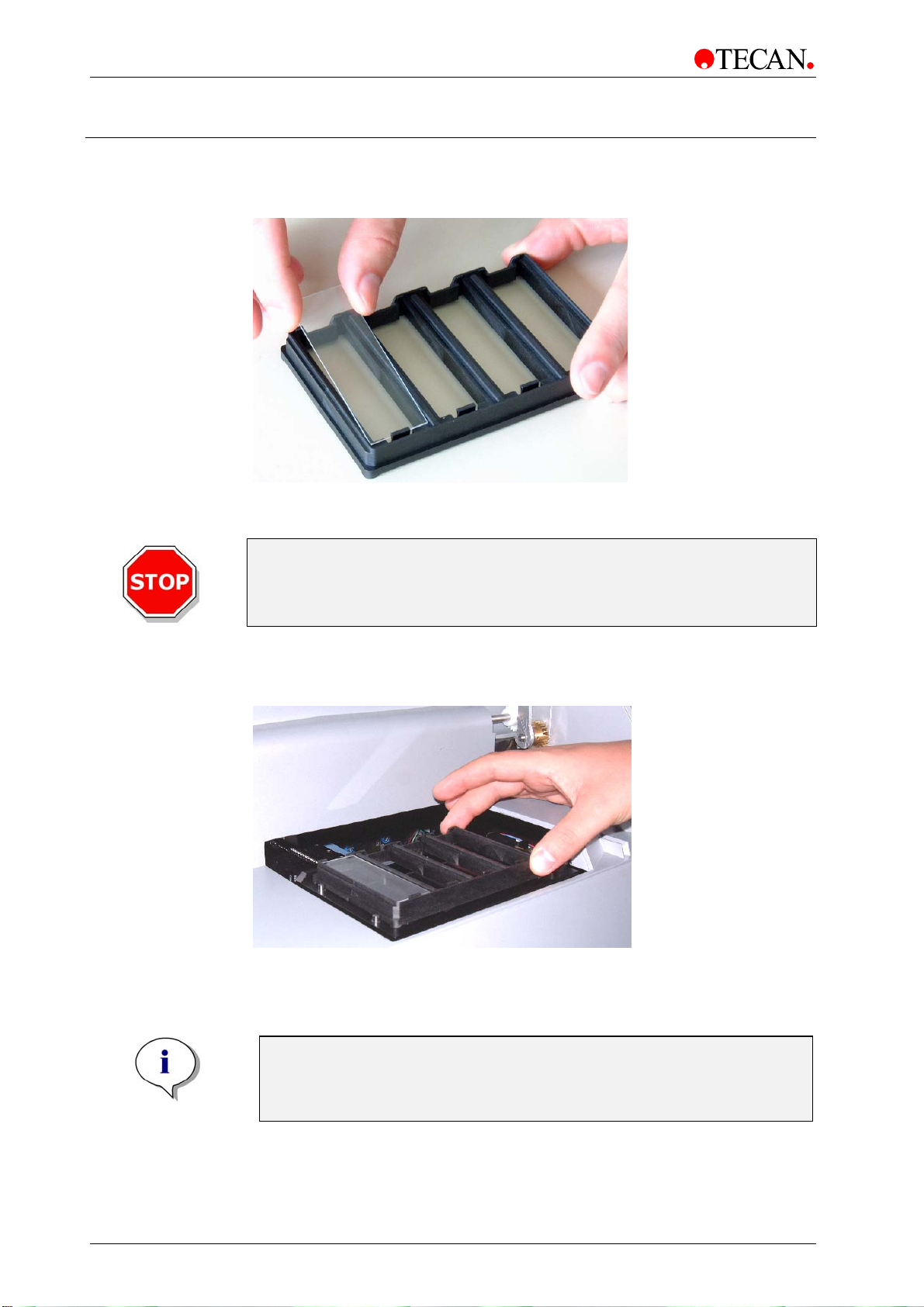
5.2 Insert Slide(s) into Slide Adapter
Insert slide(s) into slide adapter as shown below:
Figure 5.5 a
Caution
Ensure that the slide is placed tightly on its support And in the right
orientation in the adapter. If it is not placed correctly in the adapter the
Place slide adapter on the plate transport in the same orientation as shown below
(Fig. 5.5 b): - moveable spring should be located in the front
autofocus algorithm might fail to find a focal plane.
Figure 5.5 b
Note
The adapter is semi-disposable. The clamps that secure the slide might
5-4 Operating Manual for the LS Series Scanner No. 30001798 Rev. No. 1.5 2004-11
wear and the slides might become too loose in the adapter. Please call
your Tecan sales representative to order new adapters.
Page 31

6. LSServer, Scanner Shell and Download
6. LSServer, Scanner Shell and Download
6.1 Introduction
6.1.1 Overview
LSServer and Scanner Shell are software applications designed to give the user
an easy and flexible way to operate Tecan LS SERIES SCANNER instruments.
LSServer is called up in Array Pro 4.5, a special tool for analyzing microarrays,
and Scanner Shell.
LSServer Functions:
• Connecting to LS Series Scanner
• Preparing measurement parameters in order to get the best results in
scanning
• Scanning in different modes
Scanner Shell Functions:
• Connecting to Tecan LS Series Scanner
• Preparing measurement parameters in order to get the best results in
scanning
• Calibrating LS Series Scanner instruments
• Creating special formats for scanning different plates and slides
• Filter Definition
• Stacker Setup
LSDownload is a software tool needed for downloading new firmware versions to
LS SERIES SCANNER instruments.
For details on
• data analysis, see the corresponding Array Pro 4.5 operating manual.
• instrument features and technical description refer to the Tecan LS Series
Scanner operating manual.
6.1.2 Hardware Requirements
The following hardware requirements are needed for LSServer and Scanner
Shell:
Hardware Minimum Recommend
Memory 512 Mbytes 1 Gbyte
CPU Pentium III 1 GHz Pentium IV 1.7 GHz
Resolution 1024 x768 1280 x 1024
Serial Ports 2 2
2004-11 Operating Manual for the LS Series Scanner No. 30001798 Rev. No. 1.5 6-1
Page 32

6. LSServer, Scanner Shell and Download
6.1.3 Software Requirements
The following software requirements are needed for LSServer and Scanner
Shell:
Operating system Minimum Recommend
Microsoft Windows Windows 2000 Windows 2000
Additional supported software:
Array Pro 4.5 for microarray image analysis.
Note
Microsoft®Excel and Microsoft®Word must be registered by the user !
6.1.4 Software Installation Procedure
Automatic Software Setup
LSServer / Scanner Shell and LSDownload are installed by an automatic
software setup program:
Note
Before installing LSServer components be sure that Array Pro 4.5
Software for Microarray Image Analysis is installed on your system.
Note
It is necessary that the person who installs the software has administrator
rights on a PC with a Win 2000 operating system.
Step Procedure
1. Place the LS Driver for Tecan LS V2.2 Setup CD in the CD-ROM
drive.
2. Open the CD drive folder and start LSServer.exe. The installation
procedure begins.
3. A Welcome window informs the user about the beginning of the
installation process. Click Next to continue.
4. A Read Me File window informs the user about the new features of
the setup.
5. The installation of the required files is carried out and files are copied
to the computer. At the end of a successful installation the user can
quit the installation wizard by clicking the Finish button.
After successful installation, installed software components for LSServer can be
started via the Window Start menu by selecting Start - Programs - Array-Pro
Analyzer 4.5 - Array-Pro Analyzer and installed software components for
Scanner Shell and LSDownload can be started via the Window Start menu by
selecting Start - Programs - Tecan - ScannerShell or LSDownload.
6-2 Operating Manual for the LS Series Scanner No. 30001798 Rev. No. 1.5 2004-11
Page 33

6. LSServer, Scanner Shell and Download
Automatic Software Removal
Scanner Shell / LSDownload can be removed using the Windows standard
uninstall routine:
Step Procedure
1. Make sure the ScannerShell / LSDownload application is closed.
2. Select Add / Remove software from Settings - Control Panel in the
3. Select the ScannerShell / LSDownload icon and click Remove.
4. The Uninstall wizard is started. Select the preferred uninstall method
5. In the next window press Finish to uninstall ScannerShell /
6. A message box pops up asking if shared components should be
Start menu.
(Automatic or Custom) and click Next to continue.
LSDownload.
removed. Select Yes to completely uninstall application. Leaving the
components will not harm your system. If you are not sure what to do, it
is suggested that the shared components not be removed.
The ScannerShell / LSDownload is now uninstalled.
Note
This chapter does not apply to LSServer application.
2004-11 Operating Manual for the LS Series Scanner No. 30001798 Rev. No. 1.5 6-3
Page 34

6. LSServer, Scanner Shell and Download
6.2 Tecan LS Scanner Interface
6.2.1 Overview
The Tecan LS Scanner Interface is a dialog box in which the options for
connecting to instruments such as the Tecan LS Series Scanner can be set.
The next chapters describe how to:
• Set Communication port
• Choose Instrument type
• Work in Demo mode
6.2.2 Starting LS Scanner Interface
Port Setup
The Port Setup dialog box serves to set up options for connecting instruments:
The desired instrument and the communication port are chosen. The demo
mode provides the possibility to simulate any Tecan instrument.
To open the Port Setup dialog box:
• In Tecan LSA Software, Acquire menu select Tecan Scanner... or
• In Scanner Shell Software, Setup menu select Setup Port… or
• In LSDownload, Instrument menu select Connect…
The Port Setup dialog box:
In the Port Setup dialog box the instrument type and the communication port
are selected.
Alternatively, select Find any and the LSServer can automatically search for a
connected instrument.
Click OK to save changes and close the dialog box.
6-4 Operating Manual for the LS Series Scanner No. 30001798 Rev. No. 1.5 2004-11
Page 35

6. LSServer, Scanner Shell and Download
The Port Setup dialog box contains the following elements:
Instrument group box The Instrument group box contains the following
elements:
• Select option button:
A specific instrument can be selected (choose in
instrument type combo box).
• Find any option button:
The LSServer searches for available instruments
automatically.
Port group box The Port group box contains the following elements:
• Select option button:
A list in which the appropriate communication port
can be selected is shown.
• Find any option button:
The LSServer searches for any available port.
• Demo mode option button:
Allows the simulation of any instrument, e.g. for
test purposes. Refer to chapter 6.4.6 Service
Menu - Demo Mode Allowed for enabling the
demo mode.
Stacker Port group box The Stacker Port group box contains the following
elements:
• Select option button:
A list in which the appropriate communication port
can be selected is shown.
• Find any option button:
The LSServer searches for any available port.
• Demo mode option button:
Allows the simulation of an instrument. Refer to
chapter 6.4.6 Service Menu - Demo Mode Allowed
for enabling the demo mode.
• None: option button
No Stacker available for the instrument.
OK button Click OK to save data and close the dialog box.
Cancel button Click Cancel to close the dialog box. The selected
options are not saved.
Help button Click Help to display the online help for the dialog box.
2004-11 Operating Manual for the LS Series Scanner No. 30001798 Rev. No. 1.5 6-5
Page 36

6. LSServer, Scanner Shell and Download
6.3 LSServer
The LSServer is an instrument control and data scanning software specially designed for connecting to Tecan instruments such as the Tecan LS SERIES SCANNER. This chapter describes the parameters and operations; giving a general understanding in preparing and scanning data and in getting the best results for attached data analysis.
For details of data analysis see the corresponding Tecan LSA Software manual.
6.3.1 Starting the First Time
When starting LSServer for the first time, the Tecan LS Scanner Interface dialog
box is opened. After selecting instrument type and communication port and
confirming with OK the Measurement Control dialog box is displayed.
For all future starts of the LSServer:
In Tecan LSA Software, Acquire Menu select Tecan Scanner... and the
Measurement Control dialog box is displayed.
6.3.2 Measurement Control
In the Measurement control dialog box, several groups, each containing
individual buttons, are shown that offer special operations for preparing and
scanning data. Measurement parameters and measurement options are defined
and finally measurements are started here.
The Measurement Control dialog box is divided into individual groups:
• Measurement group
• Instrument group
• Measurement Parameter group
• Settings group
• Slides to Process group
6-6 Operating Manual for the LS Series Scanner No. 30001798 Rev. No. 1.5 2004-11
Page 37

Measurement
6. LSServer, Scanner Shell and Download
The Measurement Control dialog box consists of the following elements:
• The Measurement group element with the Start and Prescan button
• The Instrument group element to move plate and filters and to switch on
lasers
• The Measurement Parameter group element to Edit parameters or to
Save and Load certain predefined parameter files
• The Settings group element with the Settings button to enter the
filename and to select the scan areas
• The Slide Adapter Format group element to load existing Slide Adapter
Format (.saf) files
• The Slides to Process group element to display arrangement of the scan
areas
• File size of chosen slides
The Measurement group contains the following elements:
Start button Click the Start button to start a measurement with the
Prescan button Click the Prescan button to select three different
Instrument
The Instrument group contains the following elements:
Plate / Filter button Click the Plate / Filter button to open the Movements
Laser Control button Click the Laser Control button to open the Laser
Measurement Parameter
The Measurement parameter group contains the following elements:
current measurement parameter. The Status dialog
box is displayed.
prescan modes:
o Image prescan
o Adapter prescan
o Focus prescan
dialog box: Plate and filter can be moved.
Control dialog box: Laser type can be selected and
power control can be set / changed.
Edit button Click the Edit button to open the Measurement
Parameter dialog box: Measurement parameters can
be edited.
Load button Click the Load button to open the Open dialog box:
Measurement parameters can be loaded from a file.
Save button Click the Save button to open the Save As dialog box:
Measurement parameters can be saved to a file.
2004-11 Operating Manual for the LS Series Scanner No. 30001798 Rev. No. 1.5 6-7
Page 38

6. LSServer, Scanner Shell and Download
Settings
The Settings group contains the following elements:
Settings button Click the Settings button to open the Slide Settings
dialog box: Filename can be entered and scan areas
can be selected.
Slide Adapter Format
The Slide Adapter Format group contains the following elements:
Load button Click the Load button to open the Open Slide Adapter
Format dialog box: SAF can be selected.
Slides to Process
The Slides to process group gives a general view of the slide / plate format
used and the arrangement of available scan areas. Scan areas that will be
scanned after pressing Start / Prescan button are green, those that will not be
scanned are dark gray. Select / unselect slides with left mouse click. Also the
calculated file size will be displayed right under the scan area window.
6-8 Operating Manual for the LS Series Scanner No. 30001798 Rev. No. 1.5 2004-11
Page 39

6. LSServer, Scanner Shell and Download
f
6.3.3 File Types used in LSServer
The following file types are used with LSServer:
File Type File
Extension
Image
Measurement
Parameter
Slide adapter
ormat
Gain
calibration
Crosstalk
calibration
Focus
.tif Scanned image files are saved in a 16bit TIF
.lsp Measurement data is saved as .lsp files.
.saf Slide adapter format data is saved as .saf files.
.dat
.cvs
.dat Crosstalk data is saved as CrosstalkCor.dat
.tif Focus image files are saved as
Description
format (Tagged Image File)
Gain calibration data is saved as
GainCalibration.dat files.
Gain calibration data is stored as a comma
separated list (.cvs files). For analysis these
files can be loaded in Excel or another
calculation program.
files.
• Focus1.tif for first autofocus scan
• Focus2.tif for second autofocus scan
• Focus3.tif for third autofocus scan (only
created during MTP-autofocus)
Log
Each time the LSServer is started, the LSServer.log file is overwritten;
.log
.log1 -.log5
old data is saved in LSServer.logn file.
Log file data is saved in the following file
format:
• LSServer.log:
A record of current measurement data.
• LSServer.log1 - LSServer.log5:
A record of earlier measurement data.
Note
2004-11 Operating Manual for the LS Series Scanner No. 30001798 Rev. No. 1.5 6-9
Page 40

6. LSServer, Scanner Shell and Download
Locating Files
LSServer Files
By default the files associated with LSServer are stored as subdirectories in the
directory where LSServer.dll is found:
C:\Program Files\Common Files\Tecan\Reader\….
The subdirectories are displayed in the table below:
Temporary Files
Type of File File
Extension
Measurement
parameter
Slide adapter format
Gain calibration
Crosstalk
Temporary files needed for diagnostic and controlling purposes are stored in the
directory:
C :\Documents and Settings\user_logged_in\Local Settings\
The file types are displayed below:
Type of File File Extension Directory
Focus
Log
.lsp Parameter
.saf SAF
.dat
.csv
.dat CalData
.tif Temp
.log
.log1 to .logn
Directory
CalData
Temp
File Management
The default paths for saving files can be changed in the Slide Settings dialog
box on the Folder Options tab. See Folder Options for more information.
6-10 Operating Manual for the LS Series Scanner No. 30001798 Rev. No. 1.5 2004-11
Page 41

6. LSServer, Scanner Shell and Download
6.3.4 Measurement
Start
In the Measurement Control dialog box, Click Start…to start a measurement
using the current measurement parameters. The Status dialog box appears and
displays the current process of the scanner as static text.
In the Time group box, the Elapsed time of the measurement and the Estimated
run time are shown.
In the Gain control group box, the gain of the PMT can be adjusted online during
the measurement.
The display of the Status dialog box can be changed using the Shrink or the
Default view button.
Click Break to interrupt the measurement.
The Status dialog box contains the following elements:
Instrument is…
This static text gives information about the current
process, e.g.:
Instrument is performing autofocus
Instrument is measuring dark
Instrument is measuring image
2004-11 Operating Manual for the LS Series Scanner No. 30001798 Rev. No. 1.5 6-11
Page 42

6. LSServer, Scanner Shell and Download
Prescan
Image Prescan
Time
group box
Gain control
group box
Please wait…
progress bar
Shrink button Click Shrink to minimize the display of the Status
Default button Click Default to maximize the display of the Status
Break button Click Break to abort the current measurement.
• Elapsed time static text box
• Estimated run time static text box
• Gain 1 slider / spin control:
Use the slider or spin control to online adjust the
gain in Channel 1.
• Gain 2 slider / spin control
Use the slider or spin control to online adjust the
gain in Channel 2. (only active during dual
parallel measurements).
Please wait… under the static text a progress bar
indicates the progress of the ongoing process.
dialog box.
dialog box.
In the Measurement Control dialog box, click Prescan and select Image
Prescan to start an overview measurement for the first selected scan area.
The Image Prescan serves to position the autofocus scan lines and to select the
scan area for the final measurement. The image prescan procedure scans the
complete Slide Area as defined in the selected .saf file. It is performed using the
following default measurement parameters:
• Single Scan mode
• 40 µm scan resolution
• Large pinhole
• Optimize integration time selected
• No autofocus
• Scan Settings from Channel 1 only
6-12 Operating Manual for the LS Series Scanner No. 30001798 Rev. No. 1.5 2004-11
Page 43

6. LSServer, Scanner Shell and Download
On clicking the Image Prescan option the Status dialog box appears and an
overview measurement is started.
The Status dialog box contains the following elements:
Instrument is…
static text
The static text gives information about the actual process,
e.g.:
Instrument is performing prescan
Instrument is measuring dark
Time
group box
Gain control
group box
• Elapsed time static text box
• Estimated run time static text box
• Gain 1 slider / spin control
Use the slider or spin control to online adjust the gain in
Channel 1
• Gain 2 slider / spin control
Channel 2 is disabled in Prescan mode.
Please wait…
progress bar
Shrink
button
Default
button
Break
Please wait… under the static text a progress bar indicates
the progress of the ongoing process.
Click the Shrink button to minimize the display of the
Status dialog box.
Click the Default button to maximize the display of the
Status dialog box.
Click the Break button to abort the current measurement.
button
2004-11 Operating Manual for the LS Series Scanner No. 30001798 Rev. No. 1.5 6-13
Page 44

6. LSServer, Scanner Shell and Download
Image Prescan Dialog Box
When the image prescan of the first selected area is complete, the Image
Prescan dialog box appears with the Area Selection group box and the image
appears with an AOI (Area of Interest). The user is asked to set the Scan Area,
the Autofocus Area and the AGC Scan Area. In Tecan LS with integrated barcode
reader, it is also possible to set the Barcode Area. Click Apply to confirm the
newly defined areas. Click OK to save the settings and close the dialog box.
The Image Prescan dialog box contains the following elements:
Area Selection group box
Scan Area option button
Select the Scan Area option button to adjust the boundaries of the rectangular
AOI. To adjust a boundary, place the cursor along the edge or corner of the AOI
and drag it when the 2-way cursor appears. To move the AOI, place the cursor in
the middle of the rectangle and drag it when the 4-way cursor appears. Confirm
the AOI position by clicking the Apply button.
figure 6-1
Minimum scan area: 1mm x1mm.
AOI
6-14 Operating Manual for the LS Series Scanner No. 30001798 Rev. No. 1.5 2004-11
Page 45

6. LSServer, Scanner Shell and Download
Autofocus Area option button
Select the Autofocus Area option button to enable the
Autofocus Settings group box.
Set the Autofocus lines by adjusting the boundaries of the rectangular AOI. To
adjust a boundary, place the cursor along the edge or corner of the AOI and drag
it when the 2-way cursor appears. To move the AOI, place the cursor in the
middle of the rectangle and drag it when the 4-way cursor appears. Click Apply
to confirm the newly defined areas. If HS or Wellmode Autofocus has been
chosen, a green check mark appears and the Autofocus area is centered
automatically to the scan area.
Legend:
barcode line
autofocus lines
scan area
AGC area
figure 6-2
Minimum distance between Autofocus lines: 3mm x 3mm.
2004-11 Operating Manual for the LS Series Scanner No. 30001798 Rev. No. 1.5 6-15
Page 46

6. LSServer, Scanner Shell and Download
Barcode Area option button
Select the Barcode Area option button to enable barcode area selection.
The barcode is always read centered to the slide width and must be set within the
useable barcode area.
The Barcode Area button is enabled only if a barcode top reader is available to
the Tecan LS Series Scanner and Read barcode has been selected from the
Measurement Parameter dialog box.
Figure 6-3
The total slide area must be at least 37.5 x 15.0 mm, otherwise there is no
room for a barcode. The barcode area is from 37.5 mm to the total slide length.
If your instrument is equipped with a barcode bottom reader, the barcode
area is fixed. The barcode label has to be placed at the upper end of the
slide. The barcode must cover at least the area about 5mm away from the
upper end.
AGC Scan Area option button
Select the AGC Scan Area option button to enable the AGC area selection. If the
AGC feature is activated the selected area will be scanned and that image will be
consulted for the automatic gain calculation.
Set the AGC Scan Area lines by adjusting the boundaries of the rectangular AOI.
To adjust a boundary, place the cursor along the edge or corner of the AOI and
drag it when the 2-way cursor appears. To move the AOI, place the cursor in the
middle of the rectangle and drag it when the 4-way cursor appears. Click Apply
6-16 Operating Manual for the LS Series Scanner No. 30001798 Rev. No. 1.5 2004-11
Page 47

6. LSServer, Scanner Shell and Download
to confirm the newly defined areas, (see figure 6-2, on page 6-15 for a picture of
the AGC area). AGC is only available in:
• Single Scan Mode
• Dual Sequential Scan Mode
It is not possible in Dual Parallel Scan Mode because the Cross Talk
phenomenon with special dye combinations (e.g. Cy3 and Cy5), where signal
from one channel will be detected in the other channel and can therefore lead to
incorrectly calculated gain values. To start a scan with the AGC feature first of all
a special area for AGC must be selected. This can be done from either the
Geometry Parameters tab of the Measurement Parameter dialog box or during a
prescan from the Prescan dialog box:
Figure 6-4 Geometry Parameters tab Figure 6-5 Prescan dialog box
(For more information, see AGC (Automatic Gain Control) on page 6-37).
When a scan with AGC is started, the instrument performs a scan of the selected
AGC-area. After this scan, all pixels of that image will be calculated and will be
virtually drawn in a histogram, where the amount of pixels against the signal
values will be plotted.
2004-11 Operating Manual for the LS Series Scanner No. 30001798 Rev. No. 1.5 6-17
Page 48

6. LSServer, Scanner Shell and Download
On the Scan Settings tab of the Measurement Parameter dialog box, the values
for calculating the AGC can be set: Noise level and Signal level.
Figure 6-6 Noise level and signal level
For more information, see Scan Settings Tab on page 6-38.
Noise level: = amount of pixels in the percentage, which will be discarded
Range: 0,01% - 1%
Signal level: = mean value of all pixels in the selected signal level range
will be set to
50.000 Range: 0,01% - 1%
50.000
%Noise level %Signal level
Amount of pixels
Signal intensity
65.535
Figure 6-7 Histogram of AGC image
Noise level are pixels, which have a very high signal value and derive from dust
or other particles, which gave a high fluorescent signal. These pixels will be
excluded for the calculation. For the right gain settings only all pixels in the signal
level area will be consulted. Please keep in mind that only percentage of all pixels
can be selected and not different signal values.
6-18 Operating Manual for the LS Series Scanner No. 30001798 Rev. No. 1.5 2004-11
Page 49

6. LSServer, Scanner Shell and Download
y
A good starting point to find the right settings for the AGC will be 0,1% Noise level
and 0,1% Signal level. To increase the overall signal, the noise level and/or signal
level must be extended.
65.535
50.000
50.000
65.535
¨
Amount of pixels
Signal intensit
Amount of pixels
Signal intensity
Before AGC scan
Figure 6-8 AGC Scan Functionality; Gain setting will be adjusted to the
appropriate value. The result is an automatic increase of the gain value!
Autofocus Settings group box
Autofocus Amplitude [mm]
Enter the amplitude in mm into the Autofocus Amplitude
text box.
Select the appropriate autofocus from the Autofocus Selection group box:
• No Autofocus
• HS Autofocus
• Wellmode
• MTP mode
Select MTP in the Measurement Parameter dialog box to enable the MTP
option button.
(For further information see chapter Advanced Autofocus).
Image Prescan Buttons
After AGC scan
Apply
button
OK
button
Cancel
button
Help
button
2004-11 Operating Manual for the LS Series Scanner No. 30001798 Rev. No. 1.5 6-19
Click Apply to confirm the defined areas of the AOI.
Click OK to save data and close the dialog box.
Click Cancel to close the dialog box.
The selected options are not saved.
Click Help to display the online help for the dialog box.
Page 50

6. LSServer, Scanner Shell and Download
Adapter Prescan
In the Measurement Control dialog box, click Prescan and select Adapter
Prescan to scan the currently used MTP adapter.
The Adapter Prescan serves to define the current slide adapter format (.saf) file.
The adapter prescan procedure scans the complete traverse path of the Tecan
LS. It is performed using the following default measurement parameters:
• Single Scan mode
• 40 µm scan resolution
• Large pinhole
• Optimize integration time selected
• No autofocus
• Scan Settings from Channel 1 only
On the displayed traverse path it is possible to define the slide areas.
Enter the correct adapter height and sample height.
The chosen sample height of this dialog is taken as default height for the
following adapter scan. The total height is only taken into account to avoid
damaging the optics.
Maximum Values for total height = 16.0 mm
Maximum Value for sample height = 16.0 mm
Minimum Value for sample height = total height – 5.00 mm
Differences greater than 5.00 mm must be aborted, because of possible damage
to the optics. The software produces a warning message for differences in the
interval of 5.0 mm.
Caution
If the heights inserted in this dialog are not correctly entered, the
instrument may either become damaged or may no longer be able to
perform Its procedures correctly and the accuracy of the instrument
can no longer be guaranteed.
6-20 Operating Manual for the LS Series Scanner No. 30001798 Rev. No. 1.5 2004-11
Page 51

6. LSServer, Scanner Shell and Download
,
,
After clicking OK on the Insert Plate Heights dialog box the instrument starts the
prescan:
After the adapter prescan has finished, the scanned image is displayed. The
currently active .saf file is displayed as an overlay on the adapter prescan image.
The red rectangles represents the available scan areas. The big green rectangle
represents the outer dimension of the active area of the adapter.
After the instrument has performed the prescan, the first page of the adapter
format wizard appears.
5 mm
14 mm
5 mm
11
12
Table MTP adapter
Adapter Prescan = Non confocal scan of the complete transport-table-area.
2004-11 Operating Manual for the LS Series Scanner No. 30001798 Rev. No. 1.5 6-21
Page 52

6. LSServer, Scanner Shell and Download
The first page of the Adapter Format Wizard has the following buttons:
Reset
Click Reset to return all the values to the default settings.
button
Next
button
Cancel
button
Help
Click Next to save data temporarily and perform the second part
of the wizard.
Click Cancel to close the dialog box.
The selected options are not saved.
Click Help to display the online help for the dialog box.
button
After all the settings have been correctly entered click Next to continue to the
second page of the wizard.
Example of current SAF parameters
Slide Thickness
Total Height
Sample
Table
Shuttle
Height
Clamp
Height
Carrier
Height
MTP Adapter
6-22 Operating Manual for the LS Series Scanner No. 30001798 Rev. No. 1.5 2004-11
Page 53

6. LSServer, Scanner Shell and Download
The second page of the Adapter Format Wizard has the following buttons:
Reset
Click Reset to return all the values to the default settings.
button
Back
button
Finish
Click Back to save data temporally and perform the first part of
the wizard.
Click Finish to save data and close the wizard.
button
Cancel
button
Help
Click Cancel to close the dialog box.
The selected options are not saved.
Click Help to display the online help for the dialog box.
button
After all the settings have been correctly entered click Finish to save the settings.
The Save dialog box will then appear.
To save the Slide Adapter Format file, type in the desired filename of the newly
created .saf file and click Save.
2004-11 Operating Manual for the LS Series Scanner No. 30001798 Rev. No. 1.5 6-23
Page 54

6. LSServer, Scanner Shell and Download
Focus Prescan
In the Measurement Control dialog box, click Prescan and select Focus
Prescan to perform a focus scan of the first selected scan area of the currently
used MTP adapter.
The focus prescan enables the user to define the desired focal plane and the
focus offset on a z-scan image. This can also be used for probes, where the auto
focus fails. The focus offset can be adjusted directly on the image, so refraction
considerations are not necessary.
If no focus was previously selected, the focus prescan will be aborted with
following error message: ‘No focus mode selected. Please select focus mode in
Advanced Autofocus dialog!’
Fluorescence focus scans will be performed with the laser / filter setting of
channel 1. This focus scan mode can be relevant for gel applications. The default
settings are reflection modus with the red ( 633nm ) laser.
Click OK, and Focus Prescan dialog box appears:
Example of HS and well mode auto focus.
The Focus Prescan dialog box has the following buttons:
Reset
button
OK button Click OK to save the settings. The focus values are stored for the
Cancel
button
Help
button
6-24 Operating Manual for the LS Series Scanner No. 30001798 Rev. No. 1.5 2004-11
Click Reset to return all values to the default settings.
currently scanned slide. A message appears, which asks if the focus
offset should only be stored for this slide or for all slides of the
adapter.
Click Cancel to close the dialog box.
The selected options are not saved.
Click Help to display the online help for the dialog box.
Page 55

6. LSServer, Scanner Shell and Download
Depending on the selected focus mode, two (HS and well mode) or three (MTP
mode) focus scans will be performed.
The focus images will be displayed together with an overlay of lines, representing
the Baseline (blue), Identified/scanning plane (red) and Focus Offset (green).
Manual Focus radio button: Changes in the three combo boxes changes the
plane that will be scanned for the next image scan. This plane will be displayed
as red line in the focus images.
Focus Offset radio button: The green line represents the focus offset.
Example of focus prescan for MTP autofocus
After clicking OK, the following dialog box appears:
2004-11 Operating Manual for the LS Series Scanner No. 30001798 Rev. No. 1.5 6-25
Page 56

6. LSServer, Scanner Shell and Download
6.3.5 Instrument
Plate/ Filter
In the Measurement Control dialog box, click Plate/ Filter…to move the plate
carrier and the filter slides of certain instrument. The Movements dialog box will
appear.
In the Movements dialog box, the respective In and Out buttons can be used to
move the plate carrier into or out of the LS Series Scanner. The respective Out
buttons for the filter slides can be used to move the filter slides out of the LS
Series Scanner.
Click OK to close the dialog box.
The Movements dialog box contains the following elements:
Plate
group box
Filter Slide 1
group box
Filter Slide 2
group box
OK button Click OK to close the dialog box.
The Plate group box consists of the following elements:
• Plate In button:
Click the Plate In button to close the door and to move in the plate
transport.
• Plate Out button
Click the Plate Out button to open the door and to move out the
plate transport.
The Filter Slide 1 group box consists of the following elements:
• In button
The In button is disabled. Insert the filter slide (making sure that it
is properly oriented), until a slight resistance is felt, the LS Scanner
will automatically move the filter slide in from this point.
• Out button:
Click the Out button to move out Filter Slide 1.
The Filter Slide 2 group box consists of the following elements:
• In button
The In button is disabled. See the description for Filter slide 1.
• Out button
Click the Out button to move out Filter Slide 2.
Help button Click the Help button to display the online help for the dialog box.
6-26 Operating Manual for the LS Series Scanner No. 30001798 Rev. No. 1.5 2004-11
Page 57

Laser Control
6. LSServer, Scanner Shell and Download
In the Measurement Control dialog box, select Laser Control… and the Lamp /
Laser Control dialog box appears.
All lasers installed in your instrument are shown in the dialog box:
Click OK to save the changes and close the dialog box.
In the Laser Control dialog box specific lasers (1-4) can be activated /
deactivated and laser power can be set (Laser 4).
The Laser Control dialog box contains the following elements:
Laser 1 (633 nm)
check box
Laser 2 (532 nm)
check box
Laser 3
check box
Laser 4
check box
OK button Click OK to save the selected options and close the dialog
Cancel button Click the Cancel button to close the dialog box.
Help button Click the Help button to display the online help for the dialog
Select Laser 1 check box to activate the 633 nm laser.
Red LED is switched on at the rear of the instrument.
Select Laser 2 check box to activate the 532 nm laser.
Green LED is switched on at the rear of the instrument.
Select Laser 3 check box to activate the 594 nm laser and
the orange LED is switched on at the rear of the
instrument.
Select Laser 4 check box to activate the 488 nm laser and
the blue LED is switched on at the rear of the instrument.
(The blue laser can be power controlled).
box.
The selected options are not saved.
box.
2004-11 Operating Manual for the LS Series Scanner No. 30001798 Rev. No. 1.5 6-27
Page 58

6. LSServer, Scanner Shell and Download
6.3.6 Measurement Parameter
Edit…
In the Measurement Control dialog box, click Edit… to edit general options like
Scan Mode, Stacker and/or Barcode as well as define Geometry Parameters,
Scan Settings and Autofocus Settings. The Measurement Parameter dialog box
appears:
The Measurement Parameter dialog box contains the following elements:
• General Tab
• Geometry Parameter Tab
• Scan Settings Tab
Depending on the installed hardware features, a fourth element can also appear:
• Excitation Angle
(See 6.3.7 Excitation Angle).
OK
Cancel
Help
6-28 Operating Manual for the LS Series Scanner No. 30001798 Rev. No. 1.5 2004-11
Click OK to save the selected options and close the dialog box.
Click Cancel to close the dialog box without saving the options.
Click Help to display the online help associated with the dialog box.
Page 59

General Tab
6. LSServer, Scanner Shell and Download
In the General tab the type of Scan mode can be selected, as well as the
Barcode reader and the Stacker options for automation purposes. The user can
also select the option of having the plate move out of the instrument after
scanning.
The General tab:
The General tab contains the following elements:
• Scan Mode group box
• Stacker group box
• Plate group box
• Barcode group box
2004-11 Operating Manual for the LS Series Scanner No. 30001798 Rev. No. 1.5 6-29
Page 60

6. LSServer, Scanner Shell and Download
Scan Mode
Scan Mode
group box
In the Scan Mode group box, several scan modes can be selected.
• Single option button:
Selects the Single Scan Mode. One excitation (= laser) and one
emission (= filter) wavelength can be selected. The detection will be
performed in channel 1. This is appropriate for single label
experiments.
• Dual Sequential option button:
Selects the Dual Sequential Scan Mode. Two excitation and emission
wavelengths can be selected. This is appropriate for dual label
experiments in single channel instruments. The second label is
measured immediately after the first and the two emissions are
detected sequentially in channel 1.
• Dual Parallel option button:
Selects Dual Parallel Scan Mode. Two excitation and emission
wavelengths can be selected and are measured simultaneously. This
requires dual channel instruments as detection is performed in both
channels at once and scanning is done in half the time. The Dual
Parallel Scan Mode needs a Crosstalk correction (see Scan Settings
tab) and a valid set of K-factors in order to compensate for spectral
crosstalk.
For further information, refer to the chapter 6.4.6 Service Menu Crosstalk… description in this manual.
Stacker
Plate
Stacker
group box
Plate
group box
• Use Stacker check box:
The Use Stacker check box will be available, if a stacker is connected
to the instrument and the instrument is turned on.
Selecting Use Stacker operates the instrument in an automatic mode.
Autosave will be enabled automatically.
For further information about Stacker and Stacker Setup refer to the
chapter 6.4.6 Service Menu -
Stacker Setup… description in this manual.
See also Tecan Connect Configuration.
• Move plate out after measurement check box:
Selecting Move plate out after measurement opens the door and
moves out the plate transport after the measurement is finished.
6-30 Operating Manual for the LS Series Scanner No. 30001798 Rev. No. 1.5 2004-11
Page 61

Barcode
6. LSServer, Scanner Shell and Download
Barcode
group box
• Read barcode check box:
Read barcode will be available, if the instrument is equipped with a
barcode reader.
By selecting Read barcode the barcode is read prior to each
measurement at the user specified reading position. The barcode
appears automatically as part of the filename (see Slide Settings).
Geometry Parameter Tab
In the Geometry Parameters tab the Scan area, the location of the Autofocus
scan lines as well as the Barcode line are determined within a certain Slide
Adapter Format (saf). Different *.safs can be loaded using the Load… button.
The Slide Thickness is entered respectively.
The Geometry Parameter tab:
The Geometry Parameter tab window contains the following elements:
• Geometry group
• Slide group
• Slide Adapter Format group
2004-11 Operating Manual for the LS Series Scanner No. 30001798 Rev. No. 1.5 6-31
Page 62

6. LSServer, Scanner Shell and Download
Geometry
Geometry
group box
The Geometry group box contains the following elements:
• The static text ,which appears after “Geometry:”, displays the name of
the currently loaded *.saf file.
• Scan area option button:
Select the Scan area option button to set the appropriate scan area either by
dragging the four red borderlines by mouse or by typing in the distances,
measured from the lower left corner.
Units are given in mm.
Minimum Scan area: 1mm x 1mm
See Scan Area on page 6-34 and Scan Area option button on page 6-14, for
more information.
• Autofocus option button:
Select the Autofocus option button to specify the position of autofocus scan
lines.
The Autofocus is a scan in vertical direction (= z-scan) measuring the
reflection light of the 633 nm laser in order to bring the sample exactly into
the right focal plane. For this purpose z-scans are performed along the
autofocus scan lines that can be positioned either by dragging green lines by
mouse or by typing in the distances (units in mm), measured from the lower
margin.
The width of the autofocus scan lines is given by the Amplitude (unit in mm).
For more information, see Autofocus on page 6-35.
Select Autofocus to make the Advanced Autofocus… button available and
to change autofocus parameters or to select a different autofocus and/or
autofocus mode. For more information, see Advanced Autofocus.
Minimum Autofocus: 3mm x 3mm
• Barcode option button:
Select the Barcode option button to specify the reading position of the
barcode by dragging the blue line by mouse or by typing in the distance in
mm from the lower margin.
The total slide area must be at least 37.5 x 15.0 mm, otherwise there is no
room for a barcode. The barcode area is from 37.5 mm to the total slide
length.
This option is not available if your instrument is equipped with a
barcode bottom reader. The reading area is fixed in that case.
See Barcode on page 6-36 and Barcode Area option button on page 6-16, for
more information.
• AGC option button
Select the AGC Scan Area option button to start automatic gain control scan
area selection.
AGC is only available in:
• Single Scan Mode
• Dual Sequential Scan Mode
It is not possible in Dual Parallel Scan Mode because the Cross Talk
phenomenon with special dye combinations (e.g. Cy3 and Cy5), where signal
from one channel will be detected in the other channel and can therefore lead
to incorrectly calculated gain values.
See AGC (Automatic Gain Control) on page 6-37 and AGC Scan Area option
button on page 6-16, for more information.
6-32 Operating Manual for the LS Series Scanner No. 30001798 Rev. No. 1.5 2004-11
Page 63

Slide
6. LSServer, Scanner Shell and Download
Slide
group box
Slide Adapter Format
Slide Adapter
Format
group box
The Slide group box contains the following elements:
• Slide Thickness box:
In the Slide Thickness box the thickness of a sample (i.e. a slide)
must be entered in order to allow the instrument to search for the focal
plane within an appropriate range.
If the Slide Thickness is entered incorrectly, the algorithm might be
unable to find the right surface.
The Slide Thickness ranges from 0 to 2000 µm and must be adjusted
respectively to the Adapter height defined in *.saf files (see Advanced
Menu - Edit SAF… on page 6-85):
1) If the Adapter height is measured from the surface of the plate
transport to the surface of the spots, the Slide Thickness must
be set to 0.
2) If the Standard Tecan Slide Adapter is used (with the default
height of 11.5 mm), the thickness of the slide that is inserted
into the adapter must be edited as well.
The Slide Adapter Format group box contains the following elements:
• Load button
Click Load and the Open Slide Adapter Format dialog box appears.
Select a Slide Adapter Format (*.saf) file from the drop-down list and it
will be loaded automatically.
• Load Standard Adapter button
Click the Load Standard Adapter button to load the Standard.saf file
and to reset default Geometry Parameters.
2004-11 Operating Manual for the LS Series Scanner No. 30001798 Rev. No. 1.5 6-33
Page 64

6. LSServer, Scanner Shell and Download
Scan Area
The Geometry Parameter tab appears differently depending on which option
button has been selected :
Select the Scan Area option button to define the scan area that is displayed as a
light gray area within the red borderlines.
Minimum Scan area: 1mm x 1mm anywhere on the slide.
The Geometry Parameters tab appears as follows:
The Scan Area contains the following elements:
Top
spin control
Left
spin control
Right
spin control
Bottom spin
control
6-34 Operating Manual for the LS Series Scanner No. 30001798 Rev. No. 1.5 2004-11
Use the Top spin control or type in a value to set the upper
border of the scan area. The value is measured in mm from the
lower left corner (0/0).
Use the Left spin control or type in a value to set the left border
of the scan area. The value is measured in mm from the lower
left corner (0/0).
Use the Right spin control or type in a value to set the right
border of the scan area. The value is measured in mm from the
lower left corner (0/0).
Use the Bottom spin control or type in a value to set the bottom
border of the scan area. The value is measured in mm from the
lower left corner (0/0).
Page 65

Autofocus
6. LSServer, Scanner Shell and Download
Select the Autofocus option button to define the autofocus position and to make
the Advanced Autofocus… button available.
The Geometry Parameters tab appears as follows:
The Autofocus contains the following elements:
Top spin
control
Bottom
spin control
Amplitude
spin control
Advanced
Autofocus
button
MTP
Autofocus
Use the Top spin control or type in a value to set the autofocus
scan line for Focus 2. The value is measured in mm from the
bottom line (0/0).
Use the Bottom spin control or type in a value to set the autofocus
scan line for Focus 1. The value is measured in mm from the
bottom line (0/0).
Use the Amplitude spin control or type in a value to set the width of
autofocus scan line for both, Focus 1 and 2.
Click Advanced Autofocus to select a different autofocus mode or
to change autofocus parameter.
For detailed information please refer to the Advanced Autofocus
description in this manual.
Autofocus entered in Well or HS-Mode.
Amplitude (width of Autofocus line) from 3mm to 22mm
Distance (between Autofocus lines): from 3mm to slide length
2004-11 Operating Manual for the LS Series Scanner No. 30001798 Rev. No. 1.5 6-35
Page 66

6. LSServer, Scanner Shell and Download
Barcode
Select the Barcode option button to define the barcode reading position.
The Geometry Parameters tab appears as follows:
The Barcode window contains the following elements:
Top
spin control
Barcode must be defined in the upper half of the slide
If your instrument is equipped with a barcode bottom reader, the
barcode area is fixed. The barcode label has to be placed at the upper
end of the slide. The barcode must cover at least the area about 5mm
due to limited traveling distances in the y-direction.
Use the Top control or type in a value to set the barcode
reading position (blue line).
The barcode position is centered on the slide and
must be at least 37.5 mm from the bottom line.
The barcode reading position can not be adjusted when
using a barcode bottom reader.
Note
Note
away from the upper end.
6-36 Operating Manual for the LS Series Scanner No. 30001798 Rev. No. 1.5 2004-11
Page 67

6. LSServer, Scanner Shell and Download
AGC (Automatic Gain Control)
Select the AGC Scan Area option button to start automatic gain control scan
area selection.
The Geometry Parameters tab appears as follows:
The AGC window contains the following elements:
Top
spin control
Left
spin control
Right
spin control
Bottom spin
control
AGC is only available in:
• Single Scan Mode
• Dual Sequential Scan Mode
It is not possible in Dual Parallel Scan Mode because the Cross Talk
phenomenon with special dye combinations (e.g. Cy3 and Cy5), where signal
from one channel will be detected in the other channel and can therefore lead to
incorrectly calculated gain values.
See AGC Scan Area option button on page 6-16, for more information.
Use the Top spin control or type in a value to set the upper
border of the scan area. The value is measured in mm from the
lower left corner (0/0).
Use the Left spin control or type in a value to set the left border
of the scan area. The value is measured in mm from the lower
left corner (0/0).
Use the Right spin control or type in a value to set the right
border of the scan area. The value is measured in mm from the
lower left corner (0/0).
Use the Bottom spin control or type in a value to set the bottom
border of the scan area. The value is measured in mm from the
lower left corner (0/0).
2004-11 Operating Manual for the LS Series Scanner No. 30001798 Rev. No. 1.5 6-37
Page 68

6. LSServer, Scanner Shell and Download
Scan Settings Tab
In the Scan Settings tab the excitation and emission wavelengths can be
selected. The gain for the PMT is set respectively in one or two channels.
Pinhole, Crosstalk correction, Integration time, Sensitivity and Scan Resolution
can be defined.
Click OK to save the changes and close the dialog box.
The Scan Settings tab window:
The Scan Settings tab window contains the following group boxes:
• Optics group box
• AGC group box
• Crosstalk group box
• Integration time group box
• Sensitivity group box
• Resolution group box
6-38 Operating Manual for the LS Series Scanner No. 30001798 Rev. No. 1.5 2004-11
Page 69

Optics
6. LSServer, Scanner Shell and Download
Optics
group box
The appearance of the Optics group box is dependent on whether dual scan,
single scan or dual scan sequential is selected. In dual scan sequential Channel
st
1 1
Run and Channel 1 2
nd
Run will appear instead of Laser Channel 1 and
Laser Channel 2.
Laser Channel 1 combo box
Select the appropriate laser from the Laser Channel 1 combo box for excitation.
The selection of lasers is dependent on the type of instrument connected.
Laser Channel 2 combo box
Select the appropriate laser from the Laser Channel 2 combo box for excitation.
The selection of lasers is dependent on the type of instrument connected.
Laser Channel 2 is only activated, if Dual Parallel Scan Mode has been
selected in the General tab.
Filter Channel 1 combo box
Select the appropriate filter from the Filter Channel 1 combo box to match with
the selected excitation wavelength in Laser Channel 1.
All filters that have been defined in the filter slide which is inserted into Filter
Channel 1, can be selected from the Filter Channel 1 combo box.
Filter Channel 2 combo box
Select the appropriate filter from the Filter Channel 2 combo box to match with
the selected excitation wavelength in Laser Channel 2.
All filters that have been defined in the filter slide which is inserted into Filter
Channel 2, can be selected from the Filter Channel 2 combo box.
Filter Channel 2 is only activated, if Dual Parallel Scan Mode has been selected
in the General tab.
PMT Gain Channel 1 edit box
Set PMT Gain to a value between 70 and 255 to regulate the detector sensitivity
in Channel 1.
The PMT Gain can also be adjusted online during the measurement via the
Status control dialog box window. The Status dialog box is displayed after
clicking the Start button.
PMT Gain Channel 2 edit box
Set PMT Gain to a value between 70 and 255 to regulate the detector sensitivity
in Channel 2.
The PMT Gain can also be adjusted online during the measurement via the
Status control dialog box window. The Status dialog box is displayed after
clicking the Start button.
nd
PMT Gain Channel 2 (“Channel 1 2
Run” when Dual Scan Sequential is
selected) is only activated, if the instrument is a Dual Channel Instrument and if
Dual Parallel Scan Mode has been selected in the General tab.
Unusable filter laser excitations are signaled by red exclamation marks.
2004-11 Operating Manual for the LS Series Scanner No. 30001798 Rev. No. 1.5 6-39
Page 70

6. LSServer, Scanner Shell and Download
AGC
• Pinhole combo box
Select the appropriate pinhole for measurement from the Pinhole combo box.
Tecan LS Series Scanners have three different pinholes (Small, Medium and
Large) that can be changed using the software. The size of the pinhole
determines the grade of confocality Select between confocal and non-
confocal measurements:
Small = confocal mode (focal depth: 70 µm)
Medium = less confocal (focal depth: 300 µm)
Large = non confocal (focal depth: 800 µm)
The small pinhole gives high background rejection and better signal/background
ratio. If samples are bulky or have a large volume, larger pinholes and less
confocality give better reproducibility and higher signals.
• AGC Mode checkbox
Only available in:
Single Scan Mode
Dual Sequential Scan Mode
Not available in Dual Parallel Scan Mode due to Cross-Talk problems.
• Noise Level % = amount of pixels in the percentage, which will be
discarded; Range: 0,01% - 1%
• Signal Level % = Mean value of all pixels in the selected signal level range
will be set to 50.000
Range: 0,01% - 1%
See AGC Scan Area option button on page 6-16, for more information.
6-40 Operating Manual for the LS Series Scanner No. 30001798 Rev. No. 1.5 2004-11
Page 71

Crosstalk
6. LSServer, Scanner Shell and Download
Crosstalk
group box
The Crosstalk group box contains the following elements:
• The Crosstalk correction check box
Select Crosstalk correction to select a correction factor
(= K-factor) from the Crosstalk list box.
Dual channel instruments, operated in Dual Parallel Scan Mode, are
corrected for the spectral crosstalk from the first dye into the second
detection channel by applying K-factors.
The Crosstalk correction check box is automatically available, if a Gain
Calibration file and a Crosstalk file are found for the current laser and filter
combination (selected in the Laser Channel 1 / Channel 2 and Filter
Channel 1 / Channel 2 combo box).
Otherwise Crosstalk elements are not enabled and no crosstalk correction
factor can be set.
The defined K-factors for the current laser / filter combination are displayed
in the Crosstalk list box. Clicking on a Crosstalk list item sets the K-factor
(values appearing in K1 / K2 static text box), which will be used when
starting the next measurement, if the Crosstalk correction check box has
been selected. If the Crosstalk correction check box has not been selected
no correction is done.
• The K1 static text box displays the current selected crosstalk factor K1
(residual signal contribution from the first dye detected in the second
channel will be corrected).
• The K2 static text box displays the current selected crosstalk factor K2
(residual signal contribution from the second dye detected in the first
channel will be corrected).
• In the Crosstalk list box all crosstalk factor records, corresponding to
selected laser / filter combination, are displayed:
Format K1 = Dye 1, Name, Date
Format K2 = Dye 2, Name , Date
For further information refer to the chapter 6.4.6 Service Menu Crosstalk…in this manual.
Note
In order to obtain reliable results it is strongly recommended to place
2004-11 Operating Manual for the LS Series Scanner No. 30001798 Rev. No. 1.5 6-41
reference spots with one dye only onto your sample. These spots should
represent every dye of your experiment and should be used for QC
purposes.
Page 72

6. LSServer, Scanner Shell and Download
Integration time
Integration
time group box
Select the Optimize integration time (OIT) check box to increase the
sensitivity of the scan due to longer integration of each pixel. If the
integration time is longer more photons (i.e. more signal) are gathered for
each pixel resulting in higher intensity and better signal to noise ratio.
OIT not selected:
• Same Integration time for each scanning amplitude
• Comparable signal values for all scanning amplitudes in the same
resolution
OIT selected:
• Increase sensitivity of scan due to longer integration time of each pixel.
• Longer integration time lead to more photons, which can gathered for
each pixel.
• Higher signal to noise ratio = higher sensitivity
• Not comparable signal values between scans with different amplitudes.
• Comparable range of amplitudes:
22 mm
20 mm
15 mm
10 mm
5 mm
Sensitivity
Sensitivity
group box
Oversampling factor edit box.
Enter a certain Oversampling factor to average scan lines and to combine
them into one pixel.
Oversampling factor can be a value between 1-10.
For 4 µm scan resolution: n (max) = 3
For 6 µm scan resolution: n (max) = 4
For 10 µm scan resolution: n (max) = 8
For 20 µm scan resolution: n (max) = 10
For 40 µm scan resolution: n (max) = 10
For example, with an oversampling factor of three, one pixel is scanned
three times and the average of these values is calculated. Oversampling
therefore reduces noise but increases scan time by the factor. The average
will be calculated during scanning.
In theory, the signal to noise ratio is increased by
(n= oversampling factor). For example, a factor of 4 will increase the signal
to noise ratio by a factor of 2.
n
6-42 Operating Manual for the LS Series Scanner No. 30001798 Rev. No. 1.5 2004-11
Page 73

Resolution
6. LSServer, Scanner Shell and Download
Resolution
group box
Scan Resolution combo box displays a selection of possible resolution of 4,
6, 10, 20 and 40 µm.
The Scan Resolution is the number of µm per pixel in the x and y directions.
The smaller the value, the higher is the resolution of the image but the more
time it takes to perform a scan and the larger is the image file.
Tecan Connect Configuration
In the Measurement Control dialog box, select the General tab. Click
Configuration… and the Connect Configuration dialog box appears, in which
the plate settings and the number of plates used for the Demo Mode can
selected.
Click OK to close the dialog box and save the selected options.
Plates group
box
Laser Handling
Demo Mode
combo box
OK
button
• Read plate barcode
Enabled if Tecan Connect is installed with barcode
reader. If the checkbox is checked, a plate barcode will
be read.
• Don’t read top most plate
If this box is checked the topmost plate will be ignored for
stacking ( e.g. topmost plate can be used as light shield )
• Restack after last plate
If this box is checked, Tecan Connect will
automatically restack all plates from output stack to
input stack.
Two check boxes are available:
• Start batch run only after all lasers have reached
warm-up time
• Switch off laser after batch run has finished
• Number of plates
Enter the number of slides to be processed in
Demo Mode. Maximum is 50. These setting will be
ignored if the Tecan Connect instrument is connected.
Click the OK button to save the selected options and to close
the dialog box
2004-11 Operating Manual for the LS Series Scanner No. 30001798 Rev. No. 1.5 6-43
Page 74

6. LSServer, Scanner Shell and Download
Cancel button Click the Cancel button to close the dialog box. The selected
options are not saved.
Help
button
Advanced Autofocus
To edit the Autofocus parameters, select the Geometry Parameter tab in the
Measurement Control dialog box, and select Autofocus option button to make
Advanced Autofocus… available.
Click the Advanced Autofocus button and the Advanced Autofocus dialog box
appears.
Window Elements
The Advanced Autofocus dialog box:
Click the Help button to display the online help for the dialog
box.
The Advanced Autofocus dialog box contains following elements:
• Z-Scan Height group box
• Focus Offset controls
• Focus Gain controls
• Focal Plane group box
• Autofocus Selection group box
The Advanced Autofocus dialog box contains following buttons:
OK
button
Cancel
button
Help
button
Click the OK button to save the selected options and to close the
dialog box.
Click the Cancel button to close the dialog box. The selected
options are not saved.
Click the Help button to display the online help for the dialog box.
6-44 Operating Manual for the LS Series Scanner No. 30001798 Rev. No. 1.5 2004-11
Page 75

Z-Scan Height
6. LSServer, Scanner Shell and Download
Z-Scan Height
group box
• Slide Thickness static edit box
The Slide Thickness static box gives information about the current slide
thickness that has been defined in the Geometry Parameters tab.
The Slide Thickness is considered in displaying the slide scheme and
needs to be defined for searching the focal plane within an appropriate
range.
• Z-Scan End controls
Use the Z-Scan End controls (µm) to enter the End value of the
autofocus z-scan (= scan in vertical direction). Use the arrows or type in
the value manually.
• Z-Scan Start controls
Use the Z-Scan Start controls (µm) to enter the Start value of the
autofocus z-scan (= scan in vertical direction). Use the arrows or type in
the value manually.
For a Standard.saf file, the default start and end values for the autofocus
search area are +/- 800 µm. The range considers the tolerance of the
slide thickness, the tolerances of positioning the slide adapter to the
instrument as well as internal tolerances of the instrument itself. However,
it might be necessary to increase the z-scan to guarantee that the
algorithm finds the focal position reliably.
Higher autofocus search areas (increased z-scan distances) prolong the
time for autofocus determination.
Focus Offset
Focus
Offset
controls
• Focus Offset controls
Use the Focus Offset controls (µm) to measure a certain value below or
above a focal plane. Set the value by spinning the arrows or by typing in
the offset manually.
In certain cases the autofocus plane and the scan plane might differ, for
instance: - slides with cover glasses, slides with membranes or filters. A
certain value can be set as focus offset to perform the scan below (-) or
above (+) the focal plane.
E.g.: For a cover glass with a thickness of 170 µm, the correct focus
offset would be 113 µm, - calculated according to following formula:
Formula for the offset: d-[(n-1)/n]*d
n= refractive index of the cover glass (= 1,5)
d= thickness of cover glass
2004-11 Operating Manual for the LS Series Scanner No. 30001798 Rev. No. 1.5 6-45
Page 76

6. LSServer, Scanner Shell and Download
Focus Gain
Focus Gain
controls
Focal Plane
Focal Plane
group box
Focus Gain controls
Use the Focus Gain controls to set the PMT gain for autofocus
measurement.
The default value for the focus gain is 140. The gain is controlled
automatically and dependent on the focus intensity profiles, but can also
be adjusted manually either by using the arrows or typing in a value.
The intensity profile from autofocus scanning in z-direction shows the
different surfaces of slides (different planes). The first surface found is
defined as default focal plane, but any of three can be selected.
Plane 1
Plane 2
Plane 3
• Plane 1 option button:
Select Plane 1 option button to select Plane 1 (signal intensity) as focal
plane calculated in the order from top to bottom from the Focus.tif images.
The measurement will be performed on the selected plane 1.
• Plane 2 option button:
Select Plane 2 option button to select Plane 2 (signal intensity) as focal
plane calculated in the order from top to bottom from the Focus.tif images.
The measurement is performed on the selected second plane from the
signal intensity profile in z-direction.
• Plane 3 option button:
Select Plane 3 option button to select Plane 3 (signal intensity) as focal
plane calculated in the order from top to bottom from the Focus.tif
images. The measurement is performed on the selected third plane of the
signal profile in z.
6-46 Operating Manual for the LS Series Scanner No. 30001798 Rev. No. 1.5 2004-11
Page 77

6. LSServer, Scanner Shell and Download
Autofocus Selection
Autofocus
Selection
group box
• No Autofocus option button
Select No Autofocus option button, if no autofocus measurement is
required.
The autofocus scan prior to the measurement is skipped and the
measurement is performed at the plane that is calculated from the
Adapter height, Slide Thickness and Focus Offsets.
The scan level is calculated by considering the default height of the
Tecan MTP Slide Adapter (= 11,5 mm), the slide thickness, as well as
the Focus Offset.
No Autofocus eliminates the green autofocus scan lines from the
Geometry Parameter tab.
The No Autofocus option is recommended to use in combination with a
medium or large pinhole.
• HS Autofocus option button:
Select HS Autofocus option button to perform the so-called five point
autofocus.
To determine the right focal plane, the plate transport is moved in vertical
direction (z-direction) creating a signal intensity profile from the laser
reflection at the surface of the samples. From the 5 detection points a
focal plane will be determined.
• Well Mode option button:
Select the Well Mode option button to perform a two point autofocus prior
to measurement.
The autofocus in Well Mode is appropriate for microplates and all similar
formats, where due to wells or other reasons a continuous focal plane is
missing. The algorithm considers only the edge values in the focus.tif
image.
• MTP Mode option button:
Select MTP Mode option button to perform a triangle autofocus prior to
measurement.
The autofocus in MTP Mode performs three z-scans (Focus1, 2 and 3)
on three positions in a triangle order onto a microplate. Between these
three points the overall focal area is calculated.
2004-11 Operating Manual for the LS Series Scanner No. 30001798 Rev. No. 1.5 6-47
Page 78

6. LSServer, Scanner Shell and Download
Note
MTP Autofocus is aligned to the adapter,
i.e. all dimensions are oriented to the table.
In contrast, HS and Well Autofocus are slide oriented .
6-48 Operating Manual for the LS Series Scanner No. 30001798 Rev. No. 1.5 2004-11
Page 79

6. LSServer, Scanner Shell and Download
6.3.7 Excitation Angle Tab
The excitation beam of the laser scanner usually strikes the sample with an angle
of approximately 25° (see Figure 6-10). This improves the confocality and
minimizes unwanted stray light effects due to back reflections. Therefore this
configuration (=‘Default‘) gives the best performance for standard slides and
other flat sample formats.
However there might be applications where the default angle of incidence is not
optimal or the samples cannot be measured at all. A typical example is a
microplate with printed arrays at the bottom of the wells. When measured from
the top an inclined laser beam would usually be blocked by the walls and would
not reach the bottom of the well. The variable beamshift feature of the laser
scanner allows these samples to be measured as well. The angle of incidence for
the fluorescence excitation can be varied between 0° and 25° in steps of 0.1° via
the software.
The geometry of the sample determines the angle of incidence. The angle should
be set to a value that allows the excitation beam to excite the full area of interest
at the bottom of your sample without hitting the wall of the MTP before reaching
the measurement surface.
If the angle for the scan is changed, the angle used for autofocus should also be
adjusted. Because the autofocus does not work with normal incidence, the lowest
angle accepted by the scanner is 10°. If your sample has high walls we
recommend using the lowest possible value (=10°).
If ‘Wellmode‘ is selected (in the advanced autofocus settings menu), except for
the image scan, it is not necessary that the full area covered with spots is hit by
the laser beam for the autofocus. In that case some shadowing effect can be
tolerated. A minimum of 2.0 mm at the center part of the bottom is required
however.
Default
It is recommended to select Default for all ‘flat‘ samples (e.g. slides).
Angle is set to 25° for both the image scan and for autofocus.
2004-11 Operating Manual for the LS Series Scanner No. 30001798 Rev. No. 1.5 6-49
Page 80

6. LSServer, Scanner Shell and Download
MTP Mode
Select MTP Mode for most MTP applications.
Angle is set to 0° (normal incidence) for image scan and 10° for autofocus.
Set Beamshift
Set Beamshift may be a useful optimization parameter if your sample has only
‘flat‘ walls with a relatively low aspect ratio.
The excitation angle for the image scan can be set to any value between 0° and
25° in 0.1° increments
The angle of incidence for the autofocus scan can be set to any value between
10° and 25° in 0.1° increments
6-50 Operating Manual for the LS Series Scanner No. 30001798 Rev. No. 1.5 2004-11
Page 81

6. LSServer, Scanner Shell and Download
Increasing the angle of incidence might reduce the background in your images.
However, if it is too high for your kind of sample only a part of your sample area
could visible on the scanned image. If the autofocus angle is set too high
autofocus might fail. Use simple geometry according to figure below to calculate
the appropriate angles for your samples.
6.5
25°
Figure 6-9
Adjustable laser beam angle (0.1° increments)
High working distance (6.5 mm)
0°
6.5 mm
max object
depth
(absolut range of object height)
5-16 m m
(Set beam angle to 0° to
avoid shadows in wells)
Figure 6-10
Note
If your microplates have a transparent bottom and your process allows
them to be measured upside down it is still a good idea to compare an
upside down measurement with default settings with an upright
measurement with the angles set to MTP mode or another value
determined as optimum for your samples.
2004-11 Operating Manual for the LS Series Scanner No. 30001798 Rev. No. 1.5 6-51
Page 82

6. LSServer, Scanner Shell and Download
Load…
In the Measurement Control dialog box, click Load… to open existing
Measurement Parameter (.lsp) files. The standard Windows
appears.
In the
Open dialog box all existing Measurement Parameter files will be shown.
After selecting the requested file it will appear in the filename line. Click
load the new measurement parameters and close the dialog box.
When a Measurement Parameter file is opened the defined measurement
parameters of the file will be loaded, which include all of the settings in the
Measurement Parameter dialog box on the General, Geometry Parameter, and
Scan Settings tabs.
Note
The selection of the slides to be processed will use the default settings
The Open dialog box:
in which all slides are selected (see Slide Settings).
Open dialog box
OK to
Open dialog box is the standard Windows file open dialog box. It contains
The
the following elements:
In the
Look in
combo box
Workspace
list box
File name edit
box
Files of type
combo box
Open as read
check
only
box
Open
button
Look in combo box, the folder from which the
measurement parameter file can be opened, is selected.
The
Workspace list box shows the files and folders selected in
the
Look in combo box.
In the File name edit box the measurement parameter file can
be selected. Either type the name of the file or use the
selection to obtain a list of file names from which the
measurement parameter file can be selected.
All Tecan measurement parameter files have the file extension
Look in
*.lsp.
Select
being changed.
Click the
parameter file (*.lsp).
Open as read only to view the file and protect it from
Open button to load a selected measurement
Cancel button Click the Cancel button to close the dialog box without loading
a file.
6-52 Operating Manual for the LS Series Scanner No. 30001798 Rev. No. 1.5 2004-11
Page 83

Save…
6. LSServer, Scanner Shell and Download
In the Measurement Control dialog box, click Save… to save the current
measurement parameters under the selected filename. The standard Windows
file
Save As dialog box appears. Click OK to save the new parameters as a
Measurement Parameter (.lsp) file and close the dialog box.
When a Measurement Parameter file is saved the currently defined measurement
parameters will be saved, which include all of the settings in the Measurement
Parameter dialog box on the General, Geometry Parameter, and Scan Settings
tabs.
Note
The selection of the slides to be processed will not be saved.
If a measurement parameter file with the same name already exists it will be
overwritten.
The
Save As dialog box:
The
Save As dialog box is the standard Windows file Save As dialog box. It
contains the following elements:
In the
Save in
combo box
Workspace
list box
File Name edit
box
Save as type
combo box
Save in combo box, select the drive and the folder in
which the measurement parameter file should be saved.
The
Workspace list box shows the files and folders selected in
the Save in combo box.
Enter the File Name for your measurement parameter file or
select one from the list.
All Tecan measurement parameter files are saved with the file
extension
*.lsp.
Save button Click the Save button to save the current measurement
parameters in a file with the extension *.lsp.
Cancel button Click the Cancel button to close the dialog box without saving.
2004-11 Operating Manual for the LS Series Scanner No. 30001798 Rev. No. 1.5 6-53
Page 84

6. LSServer, Scanner Shell and Download
6.3.8 Settings
Slide Settings
In the Measurement Control dialog box, click Settings … to display the slide
setting options:
• The filename(s) of the scanned image(s)
• The slides to be processed
• If the scanned image(s) should be saved automatically or not
• If the images should be stitched or not
• If the stitched image should be flipped or not
Filename can be either a standard name or an individual Filename Format.
The
AutoSave, Stitching of resulting images or Flipping can be selected, if desired.
Under
The
Measure, select the slides to process.
Slide Settings dialog box:
The
Slide Settings tab contains the following elements:
• Filename group box
• Measure
• Filename Format
•
Date Format group box
•
Stitch resulting images check box
• Rotate image group box
• Files group box
6-54 Operating Manual for the LS Series Scanner No. 30001798 Rev. No. 1.5 2004-11
grid box
group box
Page 85

Filename
6. LSServer, Scanner Shell and Download
The Slide Settings tab also contains the following buttons:
Click
OK
button
Cancel
button
Help
button
OK to save the selected options and close the dialog box.
Click
Cancel to close the dialog box without saving the options.
Click
Help to display the online help for the dialog box.
Filename
group box
In the Filename group box a standard name for the scanned image can be
selected. This name will be part of the image filename shown later as the title of
the image window.
The
Filename group box contains the following elements:
• Select the
standard name edit box. The name gets part of the image filename.
Normally, the standard image filename is grouped as follows:
Standard name + Filename Format
The Filename Format cannot be changed. It is fixed to:
Use standard name check box to enter the name in the
▪ Barcode - excitation wavelength - slide position - current date - image
counter, - if a barcode reader is installed and if the barcode option is
selected.
▪ Excitation wavelength - slide position - current date - image counter, -
if no barcode reader is installed.
• In the
standard name edit box the image name must be entered. The
following limits must be considered:
▪ Maximum name length: 50 characters
▪ Input data allowed:
Alphanumerical data A -Z, a-z, digits 0-9 and underline.
Clear the
Measure grid box / Filename grid column)
Use standard name box to enable the Filename grid column (see
2004-11 Operating Manual for the LS Series Scanner No. 30001798 Rev. No. 1.5 6-55
Page 86

6. LSServer, Scanner Shell and Download
Measure
Measure
grid box
Before starting a scan, the slides to be processed and name(s) of the image(s)
must be defined (all slides selected is the default setting). This is done in the
Measure grid box consisting of 3 columns and a variable number of rows:
• The
For example, using a slide adapter with slide positions arranged in 2 columns
and 2 rows the Slide grid column shows:
• The Process grid column displays check boxes for each slide defined. All
Select the check boxes of the corresponding slides to be processed.
Select several rows and press
slides
Click the heading of the Process column to select all of the rows in this column.
Press
to be processed
• In the Filename grid column the image name must be entered. The
Slide grid column displays the slide position in alphanumerical order.
The first character represents the row, the second character the column
position in the defined slide adapter.
A1
= slide on position column 1 / row 1
B1
= slide on position column 1 / row 2
A2
= slide on position column 2 / row 1
B2
= side on position column 2 / row 2
slides selected are processed during next measurement.
Insert Key / Delete Key to mark the selected
to be processed / not to be processed.
Insert Key / Delete Key to mark all of the slides to be processed / not
.
following limits should be noted:
▪ Maximum name length: 50 characters
▪ Input data allowed:
Alphanumerical data A -Z, a-z, digits 0-9 and underline.
The
Filename grid column is disabled if Use standard name check box is
selected. The name entered in
filename.
The
Filename grid column is enabled if Use standard name check box is
cleared. The name entered in
filename.
standard name edit box is used creating image
Filename grid column is used creating the image
6-56 Operating Manual for the LS Series Scanner No. 30001798 Rev. No. 1.5 2004-11
Page 87

6. LSServer, Scanner Shell and Download
Filename Format
Filename
Format
group box
The Filename Format group box contains the following elements:
• The
• The
• The
The
user.
When using standard name (Use standard name check box is selected) the
filename format is fixed to:
• Barcode - excitation wavelength - slide position - current date - image
• Excitation wavelength - slide position - current date - image counter, if no
If no check boxes are enabled, the Filename Format cannot be changed.
Clear
and the
Filename Format is user-definable.
Barcode check box is automatically selected, if a barcode reader is
connected to the instrument and is enabled for use. If barcode reading fails,
barcode is set to “xxx”.
Wavelength check box must be selected, if the excitation wavelength
is to be part of the image filename.
Position check box must be selected, if the slide position is to be part
of the image filename.
Counter check box is automatically selected and cannot be reset by the
counter, if a barcode reader is installed and the barcode option is selected.
barcode reader is installed.
Use standard name to enable the following check boxes / option buttons
Date Format group box:
Wavelength check box
•
Position check box
•
Date Format
Date
Format
group box
Stitching
Stitch
resulting
images
check box
• The Date Format is automatically selected and cannot be reset by the user,
but the type of date format can be selected:
▪ DDMMYY - Day Month Year
▪ YYMMDD - Year Month Day
Select the Stitch resulting images check box to combine all scanned slides
together into one image.
The filenames used for parts of the stitched images are automatically set to
standard name.
The filename of the stitched image is set to:
Format
, where barcode option and slide position are set to “xxx”.
Standard name + fixed Filename
2004-11 Operating Manual for the LS Series Scanner No. 30001798 Rev. No. 1.5 6-57
Page 88

6. LSServer, Scanner Shell and Download
Rotate Images
Leave Images
Flip image up/down
For example, if
selected, the result will be as follows:
Flip image left/right
Flip image up/down is
For example, if
Image is not changed
Flips image vertically.
Flips image horizontally.
Flip image left/right is selected, the result will be as follows:
When
resulting images
be as follows:
Flip image up/down and Stitch
are selected, the result will
When
Flip image left/right and Stitch resulting images are selected, the
results will be as follows:
6-58 Operating Manual for the LS Series Scanner No. 30001798 Rev. No. 1.5 2004-11
Page 89

6. LSServer, Scanner Shell and Download
Rotate image
For example, if
When
as follows:
Rotates image clockwise 180°.
Rotate image is selected, the result will be as follows:
Rotate image and Stitch resulting images is selected the results will be
2004-11 Operating Manual for the LS Series Scanner No. 30001798 Rev. No. 1.5 6-59
Page 90

6. LSServer, Scanner Shell and Download
Files
AutoSave
check box
Select the AutoSave check box to save every scanned image automatically:
AutoSave on: all files will be stored in designated folder,
AutoSave off: all files will be stored in temp folder,
(see chapter Folder Options)
Filename = title of the image window = standard or special name according to
the selected options in the
Directory =
\...
The images are saved as 16bit TIF format.
Scanning of microplates or other slide adapter formats will open a lot of image
windows in the
AutoSave is automatically enabled in Stacker Mode; no user action
necessary.
To save memory and user time the first window will be closed after 10 scans.
(10 active pictures is the default setting). So the user won’t see all the scans
Tecan Array Pro Software subdirectory = Array Pro 45 \ Images
Tecan Array Pro Software.
Slide Settings tab
Note
at once, just the last 10.
Generate
JPEG
backup
check box
The image will also be saved as a .jpg file and saved in the same folder as the
.tif file.
Note
There must be an equal number of pictures in each column and in each
row, (i.e. the pictures must form a complete rectangle,
e.g. 2 x 3, 4 x 6, etc.)
Improper selection of images to be stitched can cause an unexpected
stitched image result.
6-60 Operating Manual for the LS Series Scanner No. 30001798 Rev. No. 1.5 2004-11
Page 91

6. LSServer, Scanner Shell and Download
Folder Options
In the Measurement Control dialog box, click Settings … to open the Slide
Settings dialog box:
Select the Folder Options tab to view the current file storage paths.
By clicking the
• Images (*.tif; *.jpg)
• Parameters (*.lsp)
• Adapter (*.saf)
• Temp: all files (.tif, .jpg, .lsp, .saf, autofocus images) when
not been selected, (see Files on page 6-60).
Example:
After a scan is finished:
A folder with the current date is created, (Y_M_D).
In the date folder, a folder with the current time is created, (h_m_s).
The current .lsp file will be saved as _SCAN_Time.lsp) (e.g. _SCAN_141149.lsp;
2 pm, 11 minutes and 49 seconds).
Experiment Folders:
Browse button, paths can be defined for the following file types:
AutoSave has
Date
Scan Parameter and Image files:
See also Filename Format on page 6-57.
2004-11 Operating Manual for the LS Series Scanner No. 30001798 Rev. No. 1.5 6-61
Time
Page 92

6. LSServer, Scanner Shell and Download
6.3.9 Slide Adapter Format
The Slide Adapter Format group contains the following elements:
Load button Click the Load button to open the Open Slide Adapter Format
dialog box: SAF can be selected.
See Slide Adapter Format for more information.
6.3.10 Slides to Process
The Slides to process group gives a general view of the slide / plate format
Scanlist
used and the arrangement of available
scanned after pressing
scanned are dark gray.
The selection can be changed in the Measurement dialog box. Click on a slide to
toggle its selection. For Prescan, only the first selected slide will be scanned.
Start / Prescan button are green, those that will not be
scan areas. Scan areas that will be
A scan list is a text file (.txt) for batch processing:
(e.g.: created with Notepad or Microsoft Text Editor)
Example1:
S,160,0,633,670,0,0
Scan Mode: S ( Single ), DS ( Dual Sequential), DP ( Dual Parallel )
Gain Channel1:160, Gain Channel2: 0
Laser Channel1:633
Filter Channel1:670
Laser Channel2:0
Filter Channel2:0
In this example, a single scan is performed with a gain of 160, with red laser and
red filter.
The text file must be located in the same folder as ArrayPro32.exe file. (Default
folder
C:\ArrayPro4.5).
6-62 Operating Manual for the LS Series Scanner No. 30001798 Rev. No. 1.5 2004-11
Page 93

6. LSServer, Scanner Shell and Download
When using a scanlist file the following dialog box will appear after clicking Start:
Click
Yes and the following dialog box will appear:
Click the
button is not clicked the scan starts automatically after the wait time has expired.
Example2:
Scan Mode: S ( Single ), DS ( Dual Sequential), DP ( Dual Parallel ), Scan Mode,
Gain Channel1, Gain Channel2, Laser Channel1, Filter Channel1, Laser
Channel2, Filter Channel2
In this example, three different scans are performed:
First a single scan is performed on each scan area of the adapter with a gain of
180, with red laser and red filter.
Next a dual parallel scan is performed with a gain of 220 in the first channel with
orange laser and orange filter and a gain of 190 in the second channel with blue
laser and blue filter.
Then a dual sequential scan is performed with a gain of 120 in the first channel
with red laser and red filter and a gain of 100 in the second channel with blue
laser and blue filter.
Proceed button to skip the warm up time of the laser. If the Proceed
S,180,0,633,670,0,0
DP,220,190,594,635,488,535
DS,120,100,633,670,488,535
2004-11 Operating Manual for the LS Series Scanner No. 30001798 Rev. No. 1.5 6-63
Page 94

6. LSServer, Scanner Shell and Download
6.4 LS Scanner Shell
6.4.1 General
The following chapters contain the description of the special LSServer options,
which can be viewed and utilized in the
Shell software is required for the following:
• Defining filter slides
• Locking and unlocking the instrument for transportation purposes
• Calibrating the gain of PMTs
• Defining crosstalk
• Setting up and calibrating the stacker
6.4.2 Starting Scanner Shell
Close all programs using Tecan LSServer.
Click the
The
Scanner Shell icon in the Tecan program group.
Scanner Shell window is displayed.
Scanner Shell program. The Scanner
6.4.3 Window Elements
The
Scanner Shell main window contains a menu bar, a toolbar, the window
and the status bar.
area
The
window area displays the type of the connected LSServer. For example: LS
SERIES SCANNER
Simulation.
6-64 Operating Manual for the LS Series Scanner No. 30001798 Rev. No. 1.5 2004-11
Page 95

Menu Bar
Toolbar
6. LSServer, Scanner Shell and Download
Refer to chapter 6.4.5 Scanner Shell Menus for information of the menu options.
The following buttons are available on the toolbar:
Click the About button to show the About dialog box.
It contains the following elements:
• Program information
• Version number
• Copyright
Click the Help button to display the online Help for elements such as:
• Buttons
• Menus
• Windows
Status Bar
Click the Connect button to directly connect to an instrument.
Click the Measurement button to display the Measurement Parameter
dialog box.
The Start Measurement button appears gray, because measurements
cannot be started from the Scanner Shell software.
Click this button to show the Measurement Control panel.
The Status bar displays the following information:
• Help access: Press
• Current status of the keyboard toggles:
block lock),
SCRL (Scroll lock).
F1 for Help
CAP (caps lock), NUM (Numeric
2004-11 Operating Manual for the LS Series Scanner No. 30001798 Rev. No. 1.5 6-65
Page 96

6. LSServer, Scanner Shell and Download
f
6.4.4 File types used in Scanner Shell
The following file types are used with Scanner Shell:
File Type File
Extension
Measurement
Parameter
Slide adapter
ormat
Gain
calibration
Crosstalk
calibration
Log
.lsp Measurement data is saved as .lsp files.
.saf Slide adapter format data is saved as .saf
.dat
.cvs
.dat Crosstalk data is saved as CrosstalkCor.dat
.log
.log1 - .log5
Description
files.
Gain calibration data is saved as
GainCalibration.dat files.
Gain calibration data is stored as a comma
separated list (.cvs files). For analysis these
files can be loaded in Excel or another
calculation program.
files.
Log file data is saved in the following file
format:
• LSServer.log:
A record of current measurement data.
• LSServer.log1 - LSServer.log5:
A record of earlier measurement data.
Note
Each time the Scanner Shell is started, the LSServer.log file is
overwritten; old data is saved in LSServer.logn file.
6-66 Operating Manual for the LS Series Scanner No. 30001798 Rev. No. 1.5 2004-11
Page 97

6. LSServer, Scanner Shell and Download
T
T
Locating Files
Scanner Shell Files
By default, the files associated with Scanner Shell are stored as subdirectories in
the directory where LSServer.dll is found:
C:\Program Files\Common Files\Tecan\Reader\….
The subdirectories are displayed in the table below:
Temporary Files
ype of File File
Extension
Measurement
parameter
Slide adapter format
Gain calibration
Crosstalk
Temporary files needed for diagnostic and controlling purposes are stored in the
directory:
C :\Documents and Settings\”user name”\Local Settings\
The file types are displayed below:
ype of File File Extension Directory
Focus
Log
.lsp Parameter
.saf SAF
.dat
.csv
.dat CalData
.tif Temp
.log
.log1 to .logn
Directory
CalData
Temp
File Management
Note
To see the user name of the person logged on,
press Ctrl + Alt + Delete and the user name will be shown
in the Logon dialog box.
The default paths for saving files can be changed in the Slide Settings dialog box
on the Folder Options tab. See Folder Options.
2004-11 Operating Manual for the LS Series Scanner No. 30001798 Rev. No. 1.5 6-67
Page 98

6. LSServer, Scanner Shell and Download
6.4.5 Scanner Shell Menus
File Menu
Exit
In the File menu, select Exit to exit the Scanner Shell software.
Edit Menu
Not implemented in this version of the Scanner Shell software.
View Menu
Toolbar
In the View menu, select the Toolbar option to show / hide the Scanner Shell
software Toolbar.
When the Toolbar option is selected (√) the Scanner Shell software Toolbar will
be shown.
When the Toolbar option is cleared the Scanner Shell software Toolbar will be
hidden.
Status Bar
In the View menu, select the Status Bar option to show / hide the Scanner Shell
software Status Bar.
When the Status Bar option is selected (√) the Scanner Shell software Status Bar
will be shown.
When the Status Bar option is cleared the Scanner Shell software Status Bar will
be hidden.
6-68 Operating Manual for the LS Series Scanner No. 30001798 Rev. No. 1.5 2004-11
Page 99

6. LSServer, Scanner Shell and Download
Instrument Menu
Connect
In the Instrument menu, select Connect or on the toolbar click the Connect
button or press
This option allows the connection to an instrument. Before connecting the desired
instrument the communication port must be chosen. To do this select
Port…
Setup on page 6-4 in this manual.
The desired instrument will be connected using the selected communication port.
A message in the
connection is successful or unsuccessful:
Working in Scan Mode
from the Setup menu. For further information refer to the chapter Port
Connection Message in window area of Scanner Shell
Shift + F5.
Setup
window area of Scanner Shell software shows that the
Unsuccessful
Successful
Working in Demo Mode
Connection Message in window area of Scanner Shell
Unsuccessful
Successful
Measurement Control Panel…
In the Instrument menu, select Measurement Control Panel… and the
Measurement control dialog box appears.
In the Measurement control dialog box several groups, each containing
individual buttons, are shown that offer special operations for preparing and
scanning data. Measurement parameters and measurement options are defined.
The Start and Prescan buttons are not available in the Scanner Shell software.
For further information refer to the chapter 6.3 LSServer description in this
manual.
Scanner Server Version: V 2.20
No instrument connected!
Scanner Server Version: V 2.20
LS SERIES SCANNER (+LS) 12902000004
V 3.00 08/03 IMAGING
V1.00 08/01 MEAS IMAGE iV 1.10……………….
Scanner Server Version: V 2.20
No instrument connected!
Scanner Server Version: V 2.20
LS SERIES SCANNER Simulation (+LSSim) 12345Sim
V 2.20 12 / 02 SIMULATION
V2.20 (RV1) iV 2.20……………….
2004-11 Operating Manual for the LS Series Scanner No. 30001798 Rev. No. 1.5 6-69
Page 100

6. LSServer, Scanner Shell and Download
Move Plate and Filter…
In the Instrument menu, select Move Plate and Filter… and the Movements
dialog box appears.
In the
Movements dialog box, specific In and Out buttons can be used to drive
the plate carrier or filter slides into or out of the LS Series Scanner. Click
close the dialog box.
For further information refer to the chapter Plate/ Filter on page 6-26 description
in this manual.
OK to
Edit Measurement Parameters…
In the Instrument menu, select Edit Measurement Parameters… or on the
toolbar click the
Parameter
In the
Measurement Parameter dialog box general options like Scan Mode,
Stacker and/or Barcode as well as Geometry Parameters and Scan Settings can
be defined.
For further information refer to the chapter Edit… on page 6-28 in this manual.
Edit Parameter button or press Ctrl + F5 and the Measurement
dialog box appears.
Start Measurement
Disconnect
The Start Measurement option is not available in the Instrument menu of the
Scanner Shell software.
In the Instrument menu, select the Disconnect option to disconnect the currently
connected instrument. Another instrument can then be connected.
Note
This option is only available, if an instrument is already connected.
6-70 Operating Manual for the LS Series Scanner No. 30001798 Rev. No. 1.5 2004-11
 Loading...