

Page 1

TECAN
Instructions for Use for
INFINITE M1000 PRO
Document Part No. 30064852
2011-09
Document Version No. 1.0
Page 2

WARNING
CAREFULLY READ AND FOLLOW THE INSTRUCTIONS PROVIDED IN
THIS DOCUMENT BEFORE OPERATING THE INSTRUMENT.
Notice
Every effort has been made to avoid errors in text and diagrams; however, Tecan
Austria GmbH assumes no responsibility for any errors, which may appear in this
publication.
It is the policy of Tecan Austria GmbH to improve products as new techniques
and components become available. Tecan Austria GmbH therefore reserves the
right to change specifications at any time with appropriate validation, verification,
and approvals.
We would appreciate any comments on this publication.
Manufacturer
Tecan Austria GmbH
Untersbergstr. 1A
A-5082 Grödig/Salzburg
AUSTRIA/EUROPE
T: +43 62 46 89 33
F: +43 62 46 72 770
E-mail: office.austria@tecan.com
www.tecan.com
Copyright Information
The contents of this document are the property of Tecan Austria GmbH and are
not to be copied, reproduced or transferred to another person or persons without
prior written permission.
Copyright © Tecan Austria GmbH
All rights reserved.
Printed in Austria
Declaration for EU Certificate
See the last page of these Instructions for Use.
About the Instructions for Use
Original Instructions. This document describes the INFINITE M1000 PRO
multifunctional microplate reader. It is intended as reference and instruction for
the user.
This document instructs how to:
• Install the instrument
• Operate the instrument
• Clean and maintain the instrument
Remarks on Screenshots
The version number displayed in screenshots may not always be the one of the
currently released version. Screenshots are replaced only if content related to
application has changed.
2 Instructions for Use for INFINITE M1000 PRO No. 30064852 Rev. No. 1.0 2011-09
Page 3
Trademarks
The following product names and any registered and unregistered trademarks
mentioned in this document are used for identification purposes only and remain
the exclusive property of their respective owners:
• i-control
MultiCheck
TM
, magellanTM, Infinite
TM
, Tecan
®
and the Tecan Logo are registered trademarks of
®
, Freedom EVOware
Tecan Group Ltd., Männedorf, Switzerland
®
• Windows
and Excel® are registered trademarks of Microsoft Corporation,
Redmond, WA, USA
2
TM
• BRET
• Chroma-Glo
• Greiner
is a trademark of Perkin Elmer Corporation, MA, USA
TM
®
is a trademark of Promega Corporation, WI, USA
and µClear® and are registered trademarks of Greiner
Labortechnik GmbH, Frickenhausen, Germany
®
• HTRF
• Hellma
is a registered trademark of Cisbio Bioassays, France
®
is a registered trademark of Hellma GmbH & Co. KG, Müllheim,
Germany
®
• Invitrogen
, is a registered trademark of Invitrogen Corporation Carlsbad,
USA.
®
• AlphaScreen
and AlphaLISA® are registered trademarks of Perkin Elmer,
Inc., Waltham, USA
®
, NanoQuant PlateTM,
Warnings, Cautions and Notes
The following types of notices are used in this publication to highlight important
information or to warn the user of a potentially dangerous situation:
Gives helpful information.
STOP
Indicates a possibility of instrument damage or data loss if instructions are
not followed.
WARNING
INDICATES THE POSSIBILITY OF SEVERE PERSONAL INJURY, LOSS OF
LIFE OR EQUIPMENT DAMAGE IF THE INSTRUCTIONS ARE NOT
FOLLOWED.
Note
Caution
2011-09 Instructions for Use for INFINITE M1000 PRO No. 30064852 Rev. No. 1.0 3
Page 4
WARNING
INDICATES LASER. DO NOT STARE INTO THE BEAM!
WARNING
INDICATES THE POSSIBLE PRESENCE OF BIOLOGICALLY
HAZARDOUS MATERIAL. PROPER LABORATORY SAFETY
PRECAUTIONS MUST BE OBSERVED.
WARNING
THIS SYMBOL INDICATES THE POSSIBLE PRESENCE OF FLAMMABLE
MATERIALS AND A RISK OF FIRE. PROPER LABORATORY SAFETY
PRECAUTIONS MUST BE OBSERVED.
ATTENTION
DIRECTIVE 2002/96/EC ON WASTE ELECTRICAL AND ELECTRONIC EQUIPMENT (WEEE)
NEGATIVE ENVIRONMENTAL IMPACTS ASSOCIATED WITH THE
TREATMENT OF WASTE.
z DO NOT TREAT ELECTRICAL AND ELECTRONIC EQUIPMENT
AS UNSORTED MUNICIPAL WASTE.
z COLLECT WASTE ELECTRICAL AND ELECTRONIC EQUIPMENT
SEPARATELY.
4 Instructions for Use for INFINITE M1000 PRO No. 30064852 Rev. No. 1.0 2011-09
Page 5
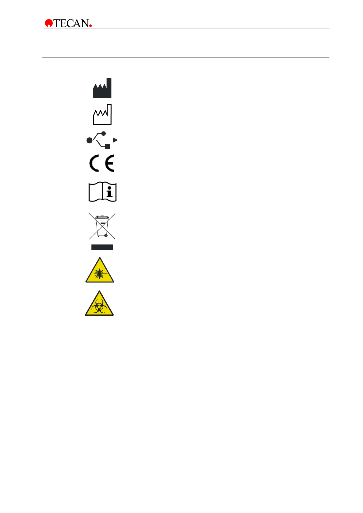
Symbols
Manufactured by
Date of manufacture
USB label
Conformité Européenne
Consult Instructions for Use
Directive 2002/96/EC on waste electrical and electronic equipment
(WEEE) symbol
Laser
Biohazardous
2011-09 Instructions for Use for INFINITE M1000 PRO No. 30064852 Rev. No. 1.0 5
Page 6

Table of Contents
1. Safety ............................................................................................ 9
1.1 Introduction ............................................................................ 9
2. General Description ................................................................... 11
2.1 Instrument ............................................................................ 11
2.1.1 Instrument Features ............................................................... 11
2.1.2 Intended Use .......................................................................... 11
2.1.3 Multifunctionality .................................................................... 12
2.1.4 Performance .......................................................................... 12
2.1.5 User Friendliness ................................................................... 12
2.1.6 System Requirements ............................................................ 14
2.2 Measurement Techniques ................................................... 15
2.2.1 Fluorescence ......................................................................... 15
2.2.2 Absorbance ............................................................................ 17
2.2.3 Luminescence ........................................................................ 18
2.2.4 AlphaScreen/AlphaLISA ........................................................ 19
2.3 Software ............................................................................... 20
2.3.1 i-control .................................................................................. 20
2.3.2 Magellan ................................................................................ 20
3. Installation .................................................................................. 21
3.1 Unpacking & Inspection ...................................................... 21
3.1.1 Inspection of Delivered Packaging ......................................... 21
3.1.2 Unpacking Instructions ........................................................... 21
3.2 Plate Carrier Transport Lock .............................................. 23
3.3 Power Requirements ........................................................... 25
3.4 Switching the Instrument ON .............................................. 25
3.5 Preparing the INFINITE M1000 PRO for Shipping ............. 27
3.6 Instrument Dimensions ....................................................... 28
3.6.1 INFINITE M1000 PRO Instrument ......................................... 28
3.6.2 INFINITE M1000 PRO Instrument with Built-in Stacker ......... 29
3.6.3 Injector Module Dimensions ................................................... 30
4. Optical System ........................................................................... 31
4.1 Fluorescence Intensity System .......................................... 31
4.1.1 Light Source System Fluorescence Intensity ......................... 32
4.1.2 Fluorescence Top/Bottom Optics ........................................... 34
4.1.3 Fluorescence Intensity Detection ........................................... 35
4.1.4 Luminescence Scan ............................................................... 36
4.2 Fluorescence Polarization System ..................................... 37
4.2.1 Light Source System Fluorescence Polarization .................... 37
4.2.2 Fluorescence Polarization Optics ........................................... 38
4.2.3 Fluorescence Polarization Detection ...................................... 40
4.2.4 Fluorescence Polarization Measurement Parameters ........... 40
4.3 Absorbance System ............................................................ 41
4.3.1 Absorbance Optics ................................................................. 42
4.3.2 Absorbance Detection ............................................................ 43
6 Instructions for Use for INFINITE M1000 PRO No. 30064852 Rev. No. 1.0 2011-09
Page 7

4.4 Luminescence System ........................................................ 43
4.4.1 Luminescence Optics ............................................................ 44
4.4.2 Luminescence Detection ....................................................... 46
4.5 AlphaScreen/AlphaLISA System ........................................ 47
4.5.1 AlphaScreen/AlphaLISA Optics ............................................. 47
4.5.2 AlphaScreen/AlphaLISA Detection ........................................ 49
4.5.3 AlphaScreen/AlphaLISA Temperature Correction ................. 49
5. Operating the INFINITE M1000 PRO ......................................... 51
5.1 Introduction ......................................................................... 51
5.2 General Operating Features ............................................... 52
5.2.1 Instrument Start Up ................................................................ 52
5.2.2 Finish a Measurement Session.............................................. 53
5.2.3 General Options ..................................................................... 53
5.3 Optimize Fluorescence Measurements ............................. 54
5.3.1 FI Scanning (Spectral Intensity Calibration) ........................... 54
5.3.2 FP Measurements ................................................................. 55
5.3.3 Instrument Parameters .......................................................... 57
5.3.4 FI Ratio Mode ........................................................................ 62
5.3.5 Optimal Read (FI Bottom Measurements Only) ..................... 62
5.3.6 Measurement Accessories .................................................... 64
5.4 Optimize Absorbance Measurements ................................ 64
5.4.1 Measurement Parameters ..................................................... 64
5.4.2 Absorbance Ratio Mode ........................................................ 65
5.4.3 Measurement Accessories .................................................... 65
5.5 Optimize Luminescence Measurements ........................... 65
5.5.1 Integration Time ..................................................................... 65
5.5.2 Light Level Attenuation .......................................................... 66
5.6 Optimize AlphaScreen/AlphaLISA ..................................... 67
5.6.1 Excitation Time ...................................................................... 67
5.6.2 Integration Time ..................................................................... 67
5.7 Injectors ............................................................................... 68
5.7.1 Measurement with Injectors ................................................... 69
5.7.2 Storage Bottles and Bottle Holders ........................................ 70
5.7.3 Injector Carrier ....................................................................... 71
5.7.4 Priming and Washing of the Injector(s) .................................. 72
5.7.5 Injector Modes and Settings (i-control) .................................. 77
5.7.6 Injector Cleaning and Maintenance ....................................... 81
5.7.7 Injector Reagent Compatibility ............................................... 83
5.8 Built-in Stacker .................................................................... 84
5.9 Barcode Scanner ................................................................. 85
6. Instrument Specifications ......................................................... 87
6.1 Introduction ......................................................................... 87
6.2 Technical Specifications ..................................................... 88
6.3 Fluorescence Intensity and Time Resolved Fluorescence
(TRF) ..................................................................................... 89
6.3.1 Definition of the Detection Limit: ............................................ 89
6.3.2 Fluorescein (Fluorescence Intensity) Top .............................. 89
2011-09 Instructions for Use for INFINITE M1000 PRO No. 30064852 Rev. No. 1.0 7
Page 8

6.3.3 Fluorescein (Fluorescence Intensity) Bottom ......................... 90
6.3.4 Europium (Time Resolved Fluorescence) .............................. 90
6.3.5 HTRF® (Time Resolved Fluorescence) .................................. 90
6.4 Fluorescence Polarization .................................................. 91
6.4.1 Fluorescein 1nM (Fluorescence Polarization) ........................ 91
6.5 Absorbance .......................................................................... 91
6.6 Luminescence ...................................................................... 92
6.6.1 ATP Glow Luminescence ....................................................... 92
6.6.2 Flash Type Luminescence ..................................................... 92
6.6.3 Dual-Color Luminescence (e.g. BRET) .................................. 93
6.7 AlphaScreen/AlphaLISA ...................................................... 93
6.8 “On the Fly” Measurements................................................ 94
6.9 Injectors ................................................................................ 94
6.9.1 Injector Performance .............................................................. 94
7. Quality Control ........................................................................... 95
7.1 Periodic Quality Control Tests ........................................... 95
7.2 Definitions ............................................................................ 96
7.2.1 Detection Limit (LOD) ............................................................ 96
7.2.2 Uniformity ............................................................................... 96
7.2.3 Linearity ................................................................................. 96
7.2.4 Accuracy ................................................................................ 96
7.2.5 Crosstalk ................................................................................ 97
7.2.6 Repeatability (Reproducibility) ............................................... 97
7.3 Acceptance Criteria ............................................................. 97
7.4 Test Instructions .................................................................. 98
7.4.1 Fluorescence Intensity ........................................................... 98
7.4.2 Time Resolved Fluorescence ............................................... 106
7.4.3 Fluorescence Polarization (FP) ............................................ 108
7.4.4 Luminescence ...................................................................... 110
7.4.5 AlphaScreen ........................................................................ 114
7.4.6 Absorbance .......................................................................... 118
8. Cleaning & Maintenance ......................................................... 123
8.1 Introduction ........................................................................ 123
8.2 Liquid Spills ....................................................................... 123
8.3 Instrument Decontamination/Disinfection ....................... 124
8.3.1 Decontamination/Disinfection Solutions ............................... 124
8.3.2 Decontamination/Disinfection Procedure ............................. 125
8.3.3 Safety Certificate .................................................................. 126
8.4 Disposal .............................................................................. 127
8.4.1 Disposal of Packing Material ................................................ 127
8.4.2 Disposal of Operating Material ............................................. 128
8.4.3 Disposal of the Instrument ................................................... 128
9. Error Messages and Troubleshooting ................................... 129
9.1 Error Messages Introduction ............................................ 129
Index ................................................................................................ 133
8 Instructions for Use for INFINITE M1000 PRO No. 30064852 Rev. No. 1.0 2011-09
Page 9

1. Safety
1. Safety
1.1 Introduction
1. Always follow basic safety precautions when using this product to reduce the risk of
injury, fire, or electrical shock.
2. Read and understand all information in the Instructions for Use. Failure to read,
understand, and follow the instructions in this document may result in damage to the
product, injury to operating personnel or poor instrument performance.
3. Observe all WARNING and CAUTION statements in this document.
4. Never open the housing of an INFINITE M1000 PRO instrument.
5. Never force a microplate into the instrument.
6. Observe proper laboratory safety precautions, such as wearing protective clothing
(powder-free gloves, safety glasses, surgical mask and protective clothing, etc. …)
and using approved laboratory safety procedures.
STOP
STOP
Caution
Tecan Austria GmbH has taken great care when creating the stored
Plate Definition Files (.pdfx) that are supplied with the instrument.
We have taken every precaution to ensure that the plate heights and
well depths are correct according to the defined plate type.
These parameters are used to determine the minimum distance between
the top of the plate and the ceiling of the measurement chamber.
Additionally, Tecan Austria has added a very small safety gap to
prevent any damage from occurring to the measurement chamber due
to small changes in plate height. This has no affect on the performance
Users MUST ensure that the plate definition file selected corresponds to
the actual plate being used. The safety gaps cannot be calculated by the
INFINITE M1000 PRO if the plate used does not match the .pdfx
Users should also take care that no potential fluorescent or luminescent
contamination lies on top of the plate (for example, droplets) and also
be aware that some plate sealers leave behind a sticky residue that
should be removed before measurements are performed.
Before starting measurements, make sure that the microplate position
of the instrument.
selected.
Caution
A1 is inserted correctly.
Caution
STOP
2011-09 Instructions for Use for INFINITE M1000 PRO No. 30064852 Rev. No. 1.0 9
To ensure the optimal performance of the INFINITE M1000 PRO
instrument, we recommend a service interval of 1 year.
Page 10
1. Safety
It is assumed that the instrument operators, because of their vocational
experience, are familiar with the necessary safety precautions for handling
chemicals and biohazardous substances.
Adhere to the following laws and guidelines:
1. National industrial protection law
2. Accident prevention regulations
3. Safety data sheets of the reagent manufacturers
WARNING
Depending on the applications, parts of the INFINITE M1000 PRO may come in
contact with biohazardous/infectious material. Make sure that only qualified
personnel operate the instrument. In case of service or when relocating or
disposing of the instrument, always disinfect the instrument according to the
directions given in these Instructions for Use.
10 Instructions for Use for INFINITE M1000 PRO No. 30064852 Rev. No. 1.0 2011-09
Page 11
2. General Description
2. General Description
2.1 Instrument
2.1.1 Instrument Features
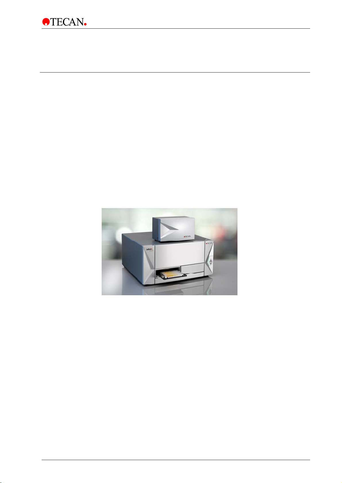
The Tecan INFINITE M1000 PRO is a multifunctional monochromator-based
microplate reader that provides high performance for the vast majority of today’s
microplate applications and research. The INFINITE M1000 PRO
exceptional flexibility in wavelength selection for absorbance and fluorescence
measurements and also enables the recording of absorbance and fluorescence
spectra.
In addition to offering absorbance and fluorescence intensity measurements, the
INFINITE M1000 PRO can also perform fluorescence polarization and
luminescence measurements (including luminescence scans) as well as
Amplified Luminescent Proximity Homogeneous Assays (AlphaScreen and
AlphaLISA).
The INFINITE M1000 PRO is also robotic compatible and offers a built-in stacker
option as well as an external injector module (see picture below).
shows
Figure 1: INFINITE M1000 PRO with injector box.
2.1.2 Intended Use
The INFINITE M1000 PRO is intended as a general purpose laboratory
instrument (Europe) and is a Class I General Controls medical device (U.S.)
for professional use, supporting common microplates conforming to the
ANSI/SBS standards.
2011-09 Instructions for Use for INFINITE M1000 PRO No. 30064852 Rev. No. 1.0 11
Page 12

2. General Description
2.1.3 Multifunctionality
The fully-equipped instrument (all options installed) provides you with the
following measurement techniques:
• Absorbance
• Absorbance Scan
• Fluorescence Intensity Top
• Fluorescence Intensity Bottom
• Fluorescence Scan (Top/Bottom)
• Time Resolved Fluorescence (TRF, TR-FRET)
• Fluorescence Polarization (FP)
• Luminescence (Glow Type, Flash Type and Dual-Color)
• Luminescence Scan (Top/Bottom)
• AlphaScreen/AlphaLISA
Any standard microplate (ranging from 6 to 1536-well formats with a maximum
plate height of 23 mm including the lid) can be measured with any of the above
measurement techniques. Switching between measurement techniques or plate
formats is fully automated: NO manual adjustments are necessary for the
INFINITE M1000 PRO. Injectors are available for microplates from 6 to 384 wells.
Tecan also provides a cuvette adapter for four standard cuvettes
(e.g. Hellma 110 QS). The cuvette must be inserted horizontally and must be
closed tightly to avoid any liquid leakage.
2.1.4 Performance
The INFINITE M1000 PRO has been designed for speed and sensitivity.
Specifications of sensitivity or precision are related to the corresponding
measurement time per microplate.
Measurement results can be optimized for different assay types (cell-based or
homogeneous), for different microplate types, and for different volume dispensing
per well. For Fluorescence Top Reading, this is accomplished by a lens system
that can be positioned within the instrument to a specific measurement height.
This adjustment can be made automatically.
2.1.5 User Friendliness
The INFINITE M1000 PRO offers unparalleled flexibility in wavelength selection
for fluorescence intensity and absorbance measurements. Any wavelength within
the specified wavelength range can be easily adjusted by the user via software.
In fluorescence mode, the bandwidth can also be selected by software. In
addition to single wavelength measurements, absorbance and fluorescence
spectra can be recorded. The measurement of spectra is possible over the entire
wavelength range.
12 Instructions for Use for INFINITE M1000 PRO No. 30064852 Rev. No. 1.0 2011-09
Page 13
2. General Description
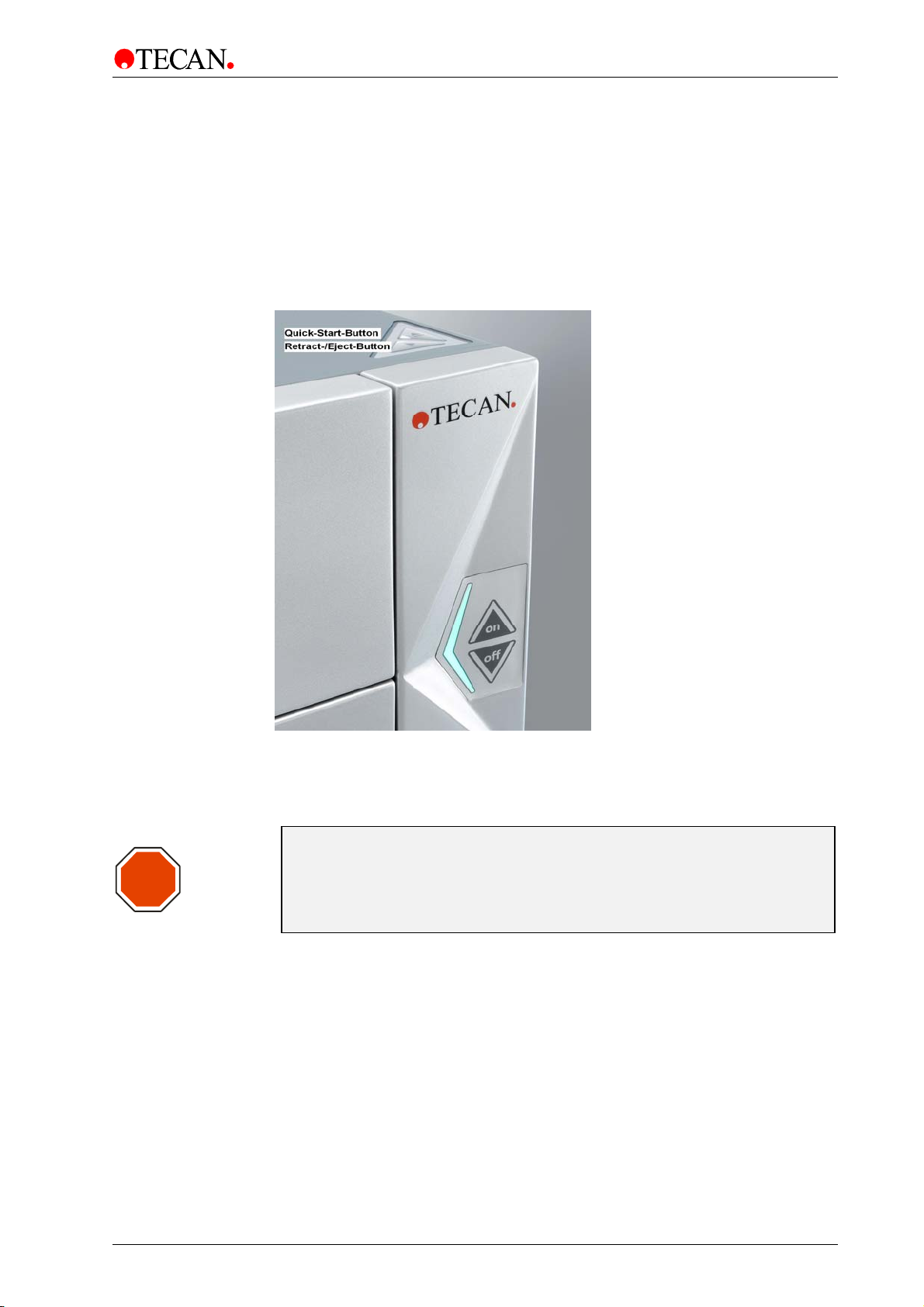
Onboard Control Buttons
In addition to the main power switch on the back panel of the instrument, the
INFINITE M1000 PRO also has onboard control buttons to simplify some
common tasks (see picture below).
An ‘On/Off’ button is available on the front to easily switch the instrument on and
off. The ‘Retract/Eject’ button allows microplates to be inserted or removed from
the instrument without starting the software. The ‘Quick-Start-Script’ button is
used to start favorite measurement scripts directly from the instrument (for further
details, see the Instructions for Use for the i-control software).
STOP
Figure 2: Onboard control buttons of the INFINITE M1000 PRO. The ‘Quick-StartScript’ button and the Retract/Eject button are located in the front right corner of
the top cover. The ‘on/off’-buttons are located on the front of the instrument.
Caution
If the instructions given in these Instructions for Use are not performed
correctly, the instrument will either be damaged or the procedures will
not be performed correctly and the safety of the instrument cannot be
guaranteed.
2011-09 Instructions for Use for INFINITE M1000 PRO No. 30064852 Rev. No. 1.0 13
Page 14

2. General Description
2.1.6 System Requirements
Minimum Recommended
Windows XP/Vista (32-bit)/Windows 7 (32- or 64-
PC
Operating
System
bit):Windows compatible PC with a Pentium compatible
processor running at 1 GHz
Windows XP (32-bit) SP3
Windows Vista (32-bit)
Windows 7 (32-bit)
Windows 7 (64-bit)
2 GHz (Dual Core)
Windows XP
(32-bit) SP3
Windows XP
Memory
Space
Requirements
Monitor Super VGA Graphics
Resolution 1024 x 768 1280 x 1024
Color Depth 256
Mouse Microsoft mouse or compatible pointing device
Communication 1 x USB 2.0
Devices
Windows Vista (32-bit)
Windows 7 (32-bit)
Windows 7 (64-bit)
700 MB 1 GB
1 x CD-ROM drive
Windows Vista
DirectX 9 graphics and 32 MB of graphics memory (for
Home Basic); 128 MB of graphics memory plus WDDM
support for all other versions
Windows 7
DirectX 9 graphics device with WDDM 1.0 or higher driver
: 512 MB RAM
: 1 GB RAM
: 1 GB RAM
: 2 GB RAM
:
:
1 GB RAM
2 GB RAM
2 GB RAM
3 GB RAM
2 x USB 2.0,
1 x RS232 (Serial)
Microsoft .NET Framework 2.0
.NET
Windows
Installer
Microsoft Excel
14 Instructions for Use for INFINITE M1000 PRO No. 30064852 Rev. No. 1.0 2011-09
If this version is not present, the install/upgrade program
will install it side-by-side with any existing installations of
the .NET Framework.
3.1
If this version is not present, the install/upgrade program
will install it.
2002
2003
2007
2010 (32-bit) – Starter edition NOT supported!
Page 15

2. General Description
2.2 Measurement Techniques
The following sections provide an introduction to the INFINITE M1000 PRO
measurement techniques. To keep this chapter compact, a few simplifications
have been made. For details, see the references.
2.2.1 Fluorescence
The INFINITE M1000 PRO offers the basic fluorescence measurement technique
and some even more sophisticated variants:
A. Fluorescence Intensity (FI, or simply Fluorescence)
B. Fluorescence Time Resolved (TRF)
C. Fluorescence Polarization (FP)
FI may also be used to measure Fluorescence Resonance Energy Transfer
(FRET). For some microplate applications, FRET offers advantages over FI and
TRF, because they simplify assay preparation. These preferably apply for mix
and measure binding studies. Compared to fluorescence polarization (FP), FRET
requires both binding partners to be labeled in a suitable way. On the other hand,
FRET may utilize TRF labels for increased sensitivity and then be referenced as
HTRF (TR-FRET). Fluorescence Time Resolved (TRF) measurements should not
be confused with Fluorescence Lifetime measurements.
Fluorescence Intensity
Fluorescent molecules emit light of specific wavelength when struck by light of
shorter wavelength (Stokes Shift). In particular, a single fluorescent molecule can
contribute one fluorescence photon (quantum of light). This is a part of the
energy, which has been absorbed before (electronic excitation), but could not be
released fast enough into thermal energy.
The average time it takes between excitation and emission is called the
fluorescence lifetime. For many fluorescent molecular species, fluorescence
lifetime is on the order of nanoseconds (prompt fluorescence). After excitation,
fluorescence emission occurs with a certain probability (quantum yield), which
depends on the fluorescent species and its environmental conditions.
For a detailed treatise on fluorescence techniques and applications see:
Principles of Fluorescence Spectroscopy by Joseph R. Lakowicz, Plenum Press
A) Fluorescence Intensity (FI)
In many microplate applications, the intensity of fluorescence emission is
measured to determine the abundance of fluorescent labeled compounds. In
these assays, other factors having an influence on fluorescence emission need to
be controlled experimentally. Temperature, pH-value, dissolved oxygen, type of
solvent, etc. may significantly affect the fluorescence quantum yield and therefore
the measurement results.
Flash Fluorescence and FI Kinetic
For high sensitivity Flash Fluorescence assays, the measurement is done just
after dispensing the activating reagent or after a short delay time.
The measurement position is not identical to the injector position. The movement
between measurement position and inject position takes ≤ 500 ms.
2011-09 Instructions for Use for INFINITE M1000 PRO No. 30064852 Rev. No. 1.0 15
Page 16

2. General Description
Fluorescence Resonance Energy Transfer (FRET)
Some microplate applications utilize a sophisticated dual labeling strategy. The
Fluorescence Resonance Energy Transfer effect (FRET) enables you to detect
binding events of various labeled compounds that are in close proximity.
Basically, FRET is a fluorescence intensity measurement of one of the two
fluorescent labels (acceptor). However, the acceptor is not susceptible to the
excitation wavelength of the light source being used. Instead, the acceptor may
receive excitation energy from the other fluorescent label (donor), if both are
spatially close together. As a prerequisite, the excitation wavelength has to apply
to the donor. And secondly, the emission spectrum of the donor has to overlap
the excitation spectrum of the acceptor (resonance condition). Nevertheless, the
transfer of excitation energy from donor to the acceptor is radiation free.
Some FRET-based applications utilize suitable pairs from the fluorescent protein
family, like GFP/YFP (Green/Yellow Fluorescent Protein) (Ref. Using GFP in
FRET-based applications by Brian A. Pollok and Roger Heim – trends in Cell
Biology (Vol.9) February 1999). An overview is given in the review article –
Application of Fluorescence Resonance Energy Transfer in the Clinical
Laboratory: Routine and Research by J. Szöllösi, et al. in Cytometry 34 page
159-179 (1998).
Other FRET-based applications take advantage of the use of TRF labels as the
donor, (for example: see. High Throughput Screening – Marcel Dekker Inc 1997
New York, Basel, Hong Kong – see section 19 Homogeneous, Time-Resolved
Fluorescence Method for Drug Discovery by Alfred J. Kolb, et al.).
B) Fluorescence Time Resolved (TRF)
TRF applies to a class of fluorescent labels (chelates) of lanthanides like
Europium (Ref. Europium and Samarium in Time-Resolved Fluoroimmunoassays
by T. Stâhlberg, et.al. - American Laboratory, December 1993 page 15) some of
them having fluorescence lifetimes in excess of 100 microseconds.
The INFINITE M1000 PRO uses a flash lamp light source with flash duration
much shorter than the fluorescence lifetime of these species. This offers the
opportunity to measure fluorescence emission at the time when stray light and
prompt fluorescence have already vanished (Lag Time) thus significantly lowering
background fluorescence and improving sensitivity.
The benefits of TRF consequently apply to assays using multiple labels with
different fluorescence lifetimes.
Homogeneous Time Resolved Fluorescence (HTRF)
HTRF technology combines both time-gated fluorescence (commonly referred to
as time-resolved fluorescence = TRF) and fluorescence resonance energy
transfer (FRET). HTRF is based on the energy transfer between two fluorescent
labels, a long-lifetime Eu
modified allophycocyanin). The main benefit of time-gated measurements is the
efficient reduction of background fluorescence by temporal discrimination. The
addition of energy transfer further minimizes several undesired assay
interferences and side effects (e.g. volume/meniscus, quenching, light scattering,
autofluorescence, molecular size, etc.). Furthermore, the homogeneous format of
these assays, so-called ‘mix and measure’ protocols, satisfies demand from the
industry for one-step, non-separating applications for high throughput screening
(HTS).
3+
-cryptate donor and the XL665 acceptor (chemically
16 Instructions for Use for INFINITE M1000 PRO No. 30064852 Rev. No. 1.0 2011-09
Page 17

2. General Description
The measurement is based on sequential detection of donor intensity (620 nm)
and acceptor intensity (665 nm) using a multi-labeling setup. A ratio of the two
intensities (acceptor:donor) is calculated and the relative energy transfer rate for
each sample is determined as Delta F (%). The fluorescence ratio is a correction
method developed by Cisbio Bioassays, which application is limited to the use of
HTRF
®
reagents and technology, and for which Cisbio Bioassays has granted a
license to Tecan. The method is covered by the US patent 5,527,684 and its
foreign equivalents.
C) Fluorescence Polarization (FP)
Fluorescence Polarization measures rotational immobility of a fluorescently
labeled compound due to its environment.
Fluorescence Polarization is defined by the following equation:
II
)(
−
⊥
⎟⎟
P
=
⎟⎟
Where
light parallel to the plane of excitation
polarized light perpendicular to the plane of excitation.
FP is suitable for binding studies, because tumbling of molecules may be
dramatically reduced after binding to a much larger site, and vice versa.
For a simplified picture of FP, fluorescent molecules may be visualized as
antennae, which need suitable orientation to pick up light waves of excitation
successfully. Using planar polarized light, only a specifically oriented subset of
the randomly oriented molecules is susceptible to excitation.
The FP measurement result will be calculated from two successive Fluorescence
Intensity measurements. They differ in the mutual orientation of polarizing filters,
one being placed behind the excitation filter, another ahead of the emission filter.
Processing both data sets, it is possible to measure the extent of how much the
fluorescent label has changed orientation in the time span between excitation and
emission.
For further information, see:
High Throughput Screening by Marcel Dekker Inc. 1997 New York, Basel, Hong
Kong – see section Fluorescence Polarization by J.R. Sportsman et al.
Polarization De La Lumière De Fluorescence Vie Moyenne Des Molécules Dans
L'etat Excité by M. Francis Perrin (Journal de Physique No:12, 1926).
P equals polarization, I
II
)(
+
⊥
equals the emission intensity of the polarized
⎟⎟
and I
equals the emission intensity of the
⊥
2.2.2 Absorbance
Absorbance is a measure for the attenuation of monochromatic light when
transmitted through a sample. Absorbance is defined as:
A = LOG
Where I
(I0 / I
10
SAMPLE
SAMPLE
is the intensity of the light being transmitted, I0 the light intensity
not attenuated by sample. The unit is assigned with O.D. (Optical Density).
Thus, 2.0 O.D. means 10
1.0 O.D. means 10
0.1 O.D. means 10
If the sample contains only one species absorbing in that narrow band of
wavelengths, the background corrected absorbance (A) is proportional to the
corresponding concentration of that species (Lambert-Beer Law).
2011-09 Instructions for Use for INFINITE M1000 PRO No. 30064852 Rev. No. 1.0 17
).
2.0
or 100-fold attenuation (1% transmission),
1.0
or 10-fold attenuation (10% transmission), and
0.1
or 1.26-fold attenuation (3.85% transmission).
Page 18
2. General Description
2.2.3 Luminescence
Caution
STOP
Glow Type Chemi- or Bioluminescence
Switch on the instrument at least 15 minutes before starting a luminescence
measurement to ensure stable conditions for the measurement.
The INFINITE M1000 PRO provides measurement of glow type chemi- or
bioluminescence. Glow type means that the luminescence assay glows much
longer than a minute. Luminescence substrates are available which provide
stable enough light output over hours.
As an example, luminescence can be measured to determine the activity of an
enzyme labeled compound (-peroxidase, -phosphatase). Light emission results
from a luminescence substrate being decomposed by the enzyme. Under excess
of substrate, the luminescence signal can be assumed to be proportional to the
abundance of the enzyme-labeled compound. As with enzyme-based assays,
control of environmental conditions is critical (temperature, pH-value).
For practical aspects of luminescence assays, see:
Bioluminescence Methods and Protocols, ed. R.A. LaRossa, Methods in
Molecular Biology 102, Humana Press, 1998
Flash Type Luminescence (with Injectors)
In flash-type luminescence assays, the measurement is only performed during
the dispensing of the activating reagent or after a short delay time.
Flash type luminescence is one of the measurement modes that can be
performed with injectors.
The plate detection sensor is only active if one of the injectors is in use
(strips “injection” or “dispense”).
During luminescence measurements, it is important to close the lid
which covers the syringes and bottles of the reagent system to minimize
Dual-color Luminescence
Selected assays emit light of two different wavelengths at the same time.
For these assays, wavelength discrimination during luminescence detection may
be required.
Tecan luminescence filters are optimized for the Chroma-Glo
system, for BRET and for BRET
wheel according to the demands of the applied assay:
• ‘Lumi Magenta’: wavelength range of 370 to 450 nm and 610 to 700 nm
• ‘Lumi Green’: wavelength range of 510 to 540 nm
• ‘Lumi Blue 1’: wavelength range of 370 to 480 nm
• ‘Lumi Green 1’: wavelength range of 520 to 570 nm
• ‘Lumi Blue’: wavelength range of 400 to 515 nm
• ‘Lumi Orange’: wavelength range of 550 to 630 nm
Note
Note
background signal.
TM
2 TM
. Filters are built into the luminescence filter
Luciferase assay
18 Instructions for Use for INFINITE M1000 PRO No. 30064852 Rev. No. 1.0 2011-09
Page 19
2. General Description
The Chroma-Glo luciferase assay generates red and green (dual-color)
luminescence from two luciferases within a single well and upon a single reagent
addition. This homogeneous dual-reporter gene assay permits each reporter to
be measured independently by detecting one well at two different wavelengths
(red and green).
Luminescence Scan
The INFINITE M1000 PRO is capable of recording emission spectra of
luminescent signals. Luminescence substrates providing stable light output are
required for luminescence scans.
As an example, emission spectra of different luciferase types (new recombinants
of Renilla or Firefly luciferase) can be recorded in order to define emission
maxima. Also environmental influences on the spectral behavior of luciferases
can be studied (pH-value, solvent, buffer).
The luminescence scanning procedure is operated by the fluorescence emission
optics, therefore additional information on the luminescence scan can be found
in chapter 4.1 Fluorescence Intensity System and chapter 5.3 Optimize
Fluoresce
nce Measurements.
2.2.4 AlphaScreen/AlphaLISA
Caution
The AlphaScreen/AlphaLISA module uses a high-power laser light source. Do
not stare into the instrument while a measurement is running.
The INFINITE M1000 PRO is able to measure Amplified Luminescent Proximity
Homogeneous Assays (AlphaScreen and AlphaLISA). Due to their
nonradioactive, homogeneous and sensitive nature, these bead-based
technologies are perfectly suited for the study of biomolecular interactions.
Upon illumination with a high-energy light source, the photosensitive molecules
contained in the donor beads produce high levels of oxyradicals. These
oxyradicals are able to travel to the acceptor beads and trigger a cascade of
reactions that ultimately lead to the generation of a strong chemiluminescent
signal.
Note
AlphaScreen/AlphaLISA measurements are only possible as endpoint
measurements in white or light gray microplates and cannot be
performed in combination with the injector system and the heating
system.
2011-09 Instructions for Use for INFINITE M1000 PRO No. 30064852 Rev. No. 1.0 19
Page 20

2. General Description
2.3 Software
The INFINITE M1000 PRO is delivered with the i-control software including
online-help and printed Instructions for Use. The software is formatted as a selfextracting archive on CD-ROM.
For advanced data reduction, Magellan software can be used to control the
INFINITE M1000 PRO.
For robotic automation INFINITE M1000 PRO is compatible with EVOware (For
more information, contact your local Tecan representative).
2.3.1 i-control
The i-control software is a user interface for stand-alone operation of the
INFINITE M1000 PRO. (For more detailed information, please refer to the
Instructions for Use for i-control). The i-control software presents the raw data for
further use in Excel.
2.3.2 Magellan
One main advantage of Magellan is that data processing capabilities are
included. In Magellan, data is organized and managed as follows:
Methods can be defined around a test. Within Magellan a method includes a test,
measurement parameters, and several options for data handling. Methods are
assay and instrument specific.
Workspaces can be built around methods. After performing a method, the
processed data will be addressed with unique sample identifiers for reporting
within a Magellan workspace. The workspace integrates sample, assay, and
instrument specific data.
The Magellan architecture provides a safe and easy to use interface, especially in
a multi-user laboratory environment. Magellan Tracker offers all the functionality
to become compliant with the FDA Regulation, 21 CFR 1040.10, except for
deviations pursuant to Laser Notice No. 50, dated June 24, 2007.
Magellan provides measurement data acquisition and customized data reduction
for your specific assays. For details, see the Instructions for Use for Magellan.
20 Instructions for Use for INFINITE M1000 PRO No. 30064852 Rev. No. 1.0 2011-09
Page 21

3. Installation
3. Installation
3.1 Unpacking & Inspection
3.1.1 Inspection of Delivered Packaging
The delivered packaging includes the following:
• OOB Quality Report
• Final test protocol
• Software (disk or CD-ROM)
• Cables (USB 2.0 and main)
• Transport lock (mounted)
• This Instructions for Use for INFINITE M1000 PRO and the IFU for i-control
Each injector module packaging includes the following:
• Bottle holder
• Beaker for priming
• 125 ml bottle (light protective)
• 15 ml bottle (light protective)
• Injector dummy (mounted)
• Waste tub for plate carrier
3.1.2 Unpacking Instructions
Before installing abide by the following instructions:
1. Visually inspect the container for damage before it is opened.
Report any damage immediately.
2. Select a location to place the instrument that is flat, level, vibration free, away
from direct sunlight, and free from dust, solvents and acid vapors. Allow at
least 10 cm distance between the back of the instrument and the wall or any
other equipment. Ensure that the plate carrier and injector carrier cannot be
accidentally hit when moved out. Ensure that the main switch and the main
cable can be reached at all times and are in no way obstructed.
3. Place the carton in an upright position and open it.
2011-09 Instructions for Use for INFINITE M1000 PRO No. 30064852 Rev. No. 1.0 21
Page 22

3. Installation
4. Lift the instrument out of the carton and place it in the selected location. Take
care when lifting the instrument and ensure that it is held on both sides.
5. Visually inspect the instrument for loose, bent or broken parts.
Report any damage immediately.
6. Compare the serial number on the rear panel of the instrument with the serial
number on the packing slip.
Report any discrepancy immediately.
7. Check the instrument accessories against the packing list.
8. Save packing materials and transport locks (see next section) for further
transportation purposes.
WARNING
The fully equipped INFINITE M1000 PRO is a precision instrument
and weighs approximately 29.5 kg. At least two people must
carefully lift the instrument from the box.
Caution
STOP
STOP
STOP
The maximum load for the INFINITE M1000 PRO cover is 20 kg;
however, the load must be distributed evenly across the entire
surface of the cover.
Caution
The maximum load for the INFINITE M1000 PRO plate transport is
300 g. Overloading the plate carrier can cause instrument damage
which may require service.
Plate carrier testing and wavelength calibration should be done
annually with the MultiCheck-Plus Test Plate to ensure the
optimal performance of the INFINITE M1000 PRO.
Caution
Allow at least 10 cm distance between the back of the instrument
and the wall or any other equipment. Do not cover instrument
while it is in operation.
22 Instructions for Use for INFINITE M1000 PRO No. 30064852 Rev. No. 1.0 2011-09
Page 23

3. Installation
3.2 Plate Carrier Transport Lock
Caution
STOP
STOP
Before the instrument is switched on for the first time,
it should be left to stand for at least 3 hours, so there is no
possibility of condensation causing a short circuit.
Caution
Remove the transport lock before operating the instrument.
The instrument is delivered with the plate carrier locked into place, so that it
cannot be damaged. Before the instrument can be used, the transport locks must
be removed using the following procedure:
1. Switch ON the computer and install the corresponding software on the
computer (i-control, Magellan or EVOware).
2. Ensure that the computer is switched OFF and the instrument's main power
switch on the back panel of the instrument is in the OFF position.
3. Connect the computer to the instrument only with the delivered USB interface
cable.
4. Insert the power cable into the main power socket (with protective earth
connection) on the back panel of the instrument.
All connected devices must be approved and listed as per IEC 60950-1
Information Technology Equipment – Safety or equivalent local standards.
5. Open the plate door manually and loosen the two outer screws from the
Transport Lock (2.5 mm Allen key is supplied).
6. Switch ON the instrument using the main power switch on the back panel of the
instrument.
7. Switch ON the computer and start the corresponding software on the computer
(i-control, Magellan or EVOware).
8. Connect the INFINITE M1000 PRO instrument via the software.
9. The software displays a message stating that the instrument is parked and
requests the loosening of the two outer screws from the Transport Lock confirm with OK.
Figure 3
2011-09 Instructions for Use for INFINITE M1000 PRO No. 30064852 Rev. No. 1.0 23
Page 24

3. Installation
10. The plate carrier moves out.
Figure 4
STOP
11. The software displays a message requesting the loosening of the two
remaining screws of the Transport Lock.
12. Loosen the two remaining screws and remove the transport lock and confirm
the software message by clicking OK.
13. The instrument will initialize and is then ready for use.
Caution
Save packing materials and transport locks for further transportation
purposes. The INFINITE M1000 PRO must be shipped only with the
original packing and installed transport locks.
24 Instructions for Use for INFINITE M1000 PRO No. 30064852 Rev. No. 1.0 2011-09
Page 25

3. Installation
3.3 Power Requirements
The instrument is auto-sensing and it is therefore unnecessary to make any
changes to the voltage range. Check the voltage specifications on the rear panel
of the instrument and ensure that the voltage supplied to the instrument is correct
to this specification.
The voltage range is from 100–120 V and 220–240 V, 50/60 Hz.
If the voltage is not correct, please contact your distributor.
Connect the instrument only to an electricity supply system with protective earth.
Caution
STOP
Do not use the instrument if the voltage setting is not correct.
If the instrument is switched ON with the incorrect voltage
setting it will be damaged.
3.4 Switching the Instrument ON
Caution
STOP
Before the instrument is switched on for the first time after
installation, it should be left to stand for at least 3 hours, so there
is no possibility of condensation causing a short circuit.
• Ensure the computer is switched OFF and the instrument's main power
switch in the back panel of the instrument is in the OFF position.
• Connect the computer to the instrument only with the delivered USB interface
cable.
• Insert the power cable into the main power socket (with protective earth
connection) in the back panel of the instrument.
• All connected devices must be approved and listed as per IEC 60950-1
Information Technology Equipment – Safety or equivalent local standards.
• Switch the instrument ON using the main power switch on the back panel of
the instrument.
WARNING
Switch off the instrument before plugging in or unplugging
the injector module.
Caution
When installing or uninstalling the instrument, ensure that the
STOP
2011-09 Instructions for Use for INFINITE M1000 PRO No. 30064852 Rev. No. 1.0 25
instrument and the computer are both switched off and disconnected
from the main power supply before the USB interface cable or any other
cables are connected or removed.
Page 26
3. Installation
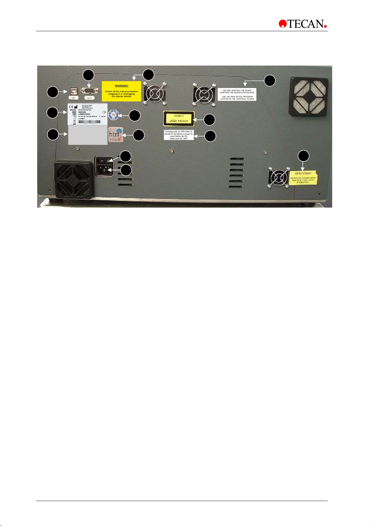
Rear View
1
2
3
Figure 5
4
12
5
6
7
8
1 USB Connection
2 Name Plate
3 Label – Options/Configuration
13
9
10
11
4 RS 232 Serial Connection
5 Label – Technical Inspection Agency
6 HTRF Label
7 Main Power Switch
8 Main Power Socket
9 Label – Class 1 Laser Product
10 Complies with 21 CFR 1040.10
except for deviations pursuant to
Laser Notice No. 50, dated June 24, 2007
11 Warranty Label
12 Warning Label: Warning! Switch off the instrument before plugging in
or unplugging the module
13 Label: Before shipping the device perform the parking procedure.
Use the park device program located in the i-control folder.
26 Instructions for Use for INFINITE M1000 PRO No. 30064852 Rev. No. 1.0 2011-09
Page 27
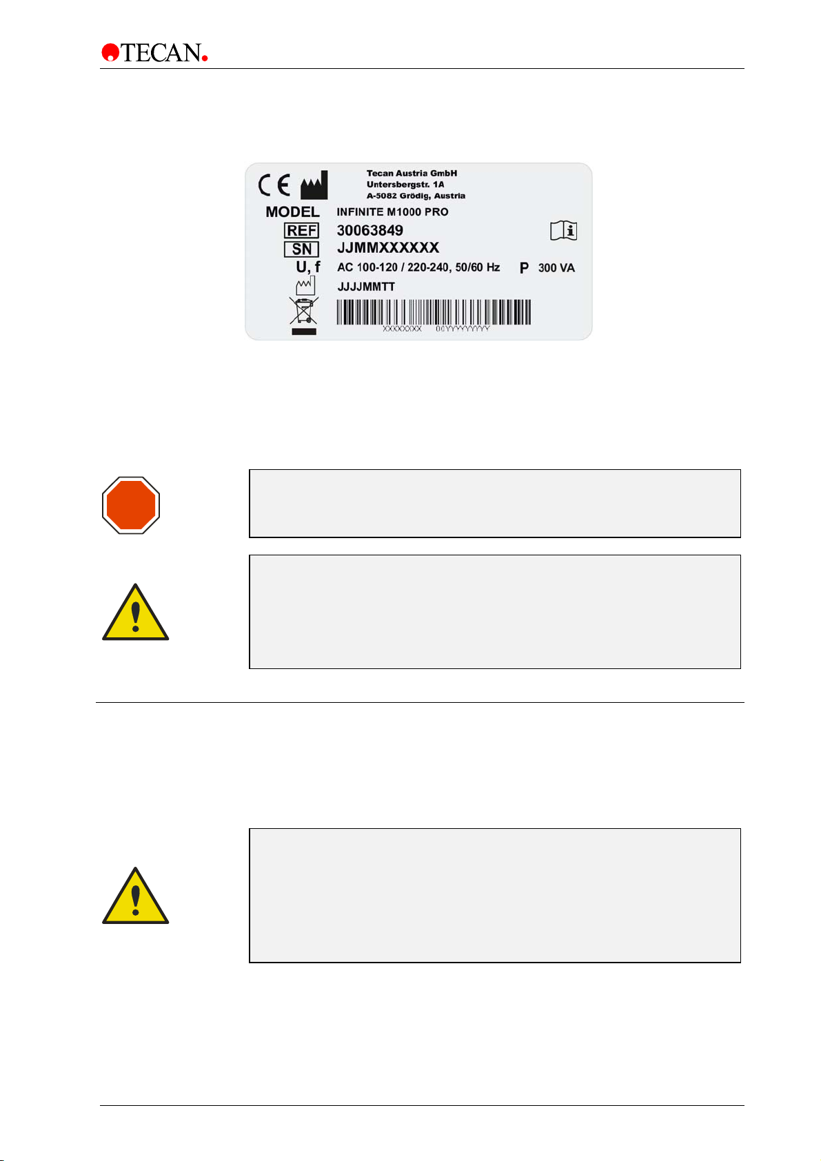
3. Installation
Example Name Plate
Contents of the name plate (e.g. model name and article number) may vary
depending on the specific model.
For an overview of the various instruments for which these Instructions for Use
are valid see the Declaration of Conformity on the last page of this document.
Caution
STOP
Only Tecan authorized service technicians are allowed to open the
instrument. Removing or breaking the warranty seal voids the warranty.
WARNING
IF THE INSTRUCTIONS GIVEN IN THIS INSTRUCTIONS FOR USE ARE
NOT CORRECTLY PERFORMED, THE INSTRUMENT WILL EITHER BE
DAMAGED OR THE PROCEDURE WILL NOT BE PERFORMED
CORRECTLY AND THE SAFETY OF THE INSTRUMENT CANNOT BE
GUARANTEED.
3.5 Preparing the INFINITE M1000 PRO for Shipping
Before shipping the INFINITE M1000 PRO, the measurement head has to be
parked to avoid any damage to the optics and plate transport. This must be
performed only by a Tecan service technician; please contact your local Tecan
representative.
BEFORE SHIPPING:
THE MEASUREMENT HEAD MUST BE PARKED AND THE TRANSPORT
LOCK MUST BE MOUNTED BEFORE SHIPPING AND THIS MUST BE
PERFORMED ONLY BY A TECAN SERVICE TECHNICIAN.
IF THE INSTRUMENT IS SHIPPED WITHOUT THESE SAFETY
MEASURES, THE INSTRUMENT GUARANTEE IS RENDERED NULL AND
VOID. USE ORIGINAL PACKAGING FOR SHIPPING.
2011-09 Instructions for Use for INFINITE M1000 PRO No. 30064852 Rev. No. 1.0 27
Page 28

3. Installation
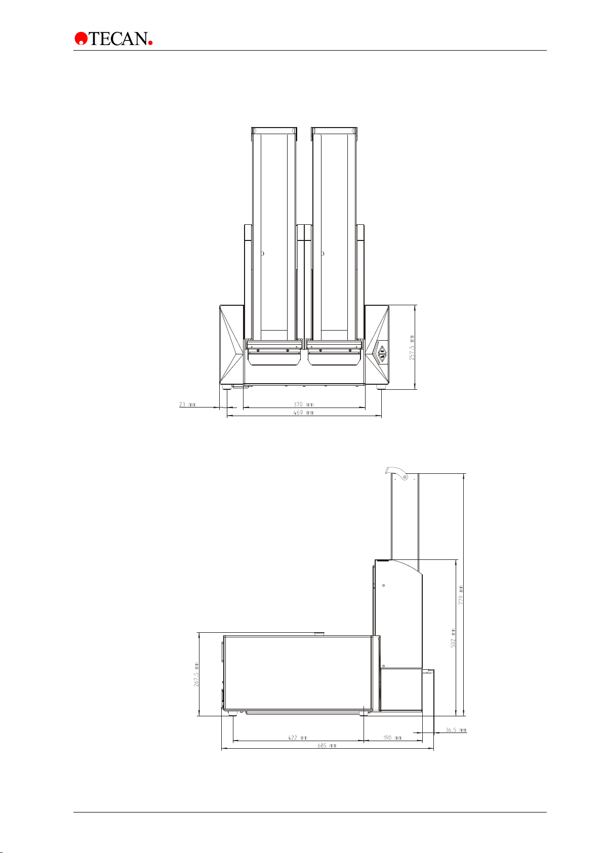
3.6 Instrument Dimensions
3.6.1 INFINITE M1000 PRO Instrument
Front View
Side View
Figure 6
Figure 7
28 Instructions for Use for INFINITE M1000 PRO No. 30064852 Rev. No. 1.0 2011-09
Page 29
3. Installation
3.6.2 INFINITE M1000 PRO Instrument with Built-in Stacker
Front View with Built-in Stacker
Figure 8
Side View with Built-in Stacker
Figure 9
2011-09 Instructions for Use for INFINITE M1000 PRO No. 30064852 Rev. No. 1.0 29
Page 30
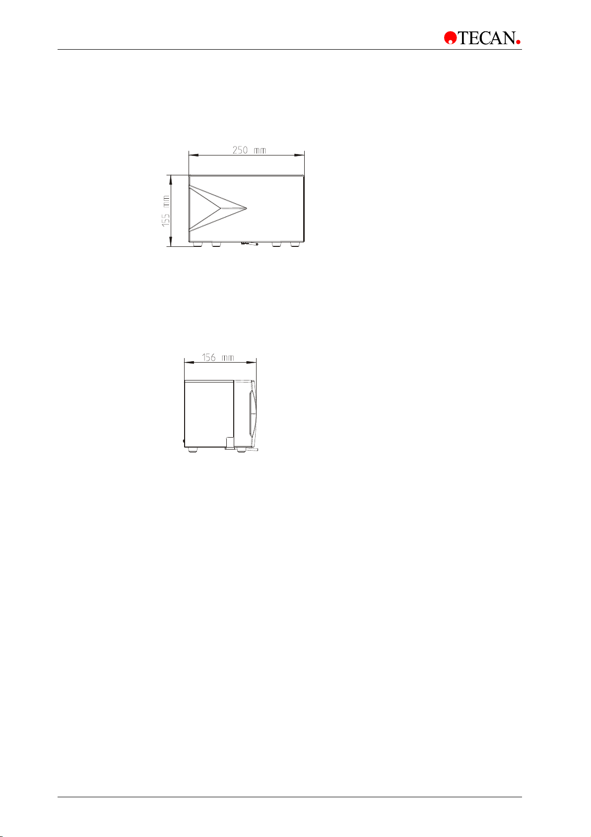
3. Installation
3.6.3 Injector Module Dimensions
Front View
Figure 10
Side View
Figure 11
30 Instructions for Use for INFINITE M1000 PRO No. 30064852 Rev. No. 1.0 2011-09
Page 31
4. Optical System
4. Optical System
4.1 Fluorescence Intensity System
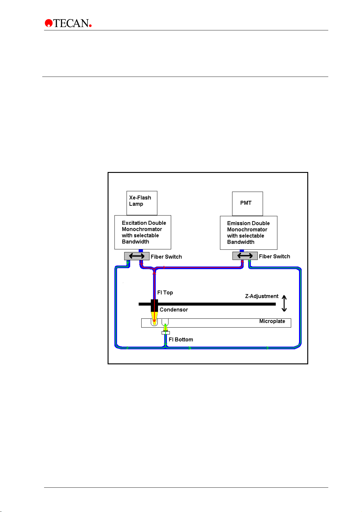
The INFINITE M1000 PRO fluorescence optical system is sketched below. The
path of fluorescence top light goes from the light source, to and from the top
measurement head and to the PMT. The path of fluorescence bottom light goes
from the light source, to and from the bottom measurement head and to the PMT.
The system is consists of:
1) the light source system, 2) the fluorescence top optics, 3) the fluorescence
bottom optics and 4) the fluorescence detection unit.
1)
Fluorescence TOP light
2)
3)
Fluorescence BOTTOM light
Figure 12: Optical System Fluorescence Top and Bottom
4)
2011-09 Instructions for Use for INFINITE M1000 PRO No. 30064852 Rev. No. 1.0 31
Page 32

4. Optical System
4.1.1 Light Source System Fluorescence Intensity
Fluorescence applications usually require a specific range of excitation
wavelengths. Additionally, pulsed excitation light may be required (Time Resolved
Fluorescence, TRF).
The INFINITE M1000 PRO light source system is built from the following
components:
1. Flash lamp
2. Condensing optics
3. Order sorting filter wheel
4. Excitation double monochromator
5. Fiber optic bundle
6. Flash lamp monitor
Flash Lamp
The INFINITE M1000 PRO utilizes a high energy Xenon arc discharge lamp
(flash lamp). The flash sparks across a small gap between two electrodes. The
lamp bulb contains a high pressure Xenon atmosphere. The flash decays within
some microseconds.
The INFINITE M1000 PRO uses the flash lamp for fluorescence and for
absorbance measurements - although pulsed illumination is a must only for TRF.
The main benefits of this singular kind of lamp are:
a) High intensity from the deep UV to the near IR
b) Very long lifetime
c) Many applications - only one kind of lamp
d) No warm up time required
Condenser
Condenser type optics from fused silica focus the flashlight onto the entrance slit
of the excitation monochromator.
Order Sorting Filter Wheel
A filter wheel is located between the condenser and the excitation
monochromator. The filter wheel contains wavelength specific optical filters,
which are necessary to block undesired diffraction orders produced by the optical
gratings. The filters are set automatically.
Excitation Double Monochromator
In both fluorescence and absorbance applications, the excitation monochromator
is used to select any desired wavelengths from the flash lamp spectrum in the
range from 230 nm to 850 nm for fluorescence intensity and from 230 nm to
1000 nm for absorbance applications.
In many cases, fluorescence emission spectra do not depend on the exact
excitation wavelength; therefore, for maximum total fluorescence signal, a broad
excitation bandwidth should be used. For measurements > 300 nm, the
bandwidth can be selected continuously from 5 nm to 20 nm in 1 nm steps.
For measurements ≤ 300 nm, the bandwidth can be selected continuously
from 2.5 to 10 nm in 0.5 nm steps.
For a more detailed description of how a monochromator works, see below.
32 Instructions for Use for INFINITE M1000 PRO No. 30064852 Rev. No. 1.0 2011-09
Page 33

4. Optical System
How a Monochromator Works
A monochromator is an optical instrument that enables any wavelength to be
selected from a defined optical spectrum. Its method of operation can be
compared to a tunable optical filter, which allows both the wavelength and
bandwidth to be adjusted.
A monochromator consists of an entrance slit, a dispersive element and an exit
slit. The dispersive element diffracts the light into the optical spectrum and
projects it onto the exit slit. A dispersive element can be realized by using a glass
prism or an optical grating. Modern monochromators such as those used in the
INFINITE M1000 PRO are designed with optical gratings.
Rotating the optical grating around its vertical axis moves the spectrum across
the exit slit and only a small part of the spectrum (bandpass) passes through the
exit slit. This means that when the monochromator entrance slit is illuminated with
white light, only light with a specific wavelength (monochromatic light) passes
through the exit slit. The wavelength of this light is set by the rotation angle of the
optical grating. The bandwidth is set by the width of the exit slit. The bandwidth is
defined as Full Width at Half Maximum intensity (FWHM).
Monochromators block undesired wavelengths, typically amounting to 10
means when the monochromator is set for light with a wavelength of 500 nm and
the detector detects a signal of 10,000 counts, light with different wavelengths
creates a signal of only 10 counts. For applications in the fluorescence range this
blocking is often not sufficient, since the fluorescence light to be detected is
usually much weaker than the excitation light. To achieve a higher level of
blocking, two monochromators are connected in series, i.e. the exit slit of the first
monochromator acts as the entrance slit of the second monochromator
simultaneously. This is known as a double monochromator. In this case, the
blocking count reaches a factor of 10
filters.
In the INFINITE M1000 PRO, a double monochromator is installed on both the
excitation and detection side. This allows easy selection of arbitrary excitation
and emission wavelengths.
3
. This
6
, a value typically achieved by interference
Fiber optic bundle
Flash lamp monitor
From the exit slit of the excitation monochromator, the light will be coupled into a
fiber optic bundle guiding the light either to the top measuring optics or the bottom
measuring optics (Figure 12). The lower end of each fiber bundle acts as a color
cific light source. In both cases, a small portion of the light is always guided to
spe
the flash lamp monitor diode.
The light energy of single flashes may fluctuate slightly. To take these variations
into account, a silicon photodiode monitors the energy of every single flash.
Fluorescence and Absorbance measurement results are compensated
correspondingly.
2011-09 Instructions for Use for INFINITE M1000 PRO No. 30064852 Rev. No. 1.0 33
Page 34

4. Optical System
4.1.2 Fluorescence Top/Bottom Optics
Flash light enters the optical system and is focused by the condenser onto the
entrance slit of the excitation monochromator. The wavelength and bandwidth of
the excitation light is selected within the monochromator. After passing the
monochromator, the excitation light is coupled into a fiber bundle which guides
the light to the top or bottom measuring head. The light is then focused into the
sample by the top/bottom lens system (Figure 13, left-hand side).
The fluoresce
coupled into the fluorescence fibers bundle (Figure 13, right-hand side) and
d to the detection system.
guide
Z-Positioning (Top Fluorescence only)
The Z-position of the fluorescence top optics can be adjusted. As light is
refracted onto the sample liquid surface, a Z-adjustment helps to maximize signal
to noise.
The fluorescence measuring Top and Bottom Optics are built from the following
components:
1. Fluorescence Intensity Lens System Top/Bottom
2. Fluorescence Fiber Bundle
nce emission light is collected by the top/bottom lens system again,
Fluorescence Intensity Lens System
The exit side of the bundle acts as a color specific light source. The lens system
at the end of the excitation top and bottom fibers is designed to focus the
excitation light into the sample and also collect the fluorescence light and focus it
back onto the fluorescence fiber bundle.
The objective lenses are made from fused silica. This material provides high UV
transmission and is virtually void of auto-fluorescence.
Fluorescence Fiber Bundle
The fiber bundle plugged into the top/bottom measuring head contains a
homogeneous mixture of both excitation and emission fibers. The emission fibers
guide the fluorescence light to the emission monochromator head where a lens
system focus the light onto the entrance slit of the emission monochromator.
34 Instructions for Use for INFINITE M1000 PRO No. 30064852 Rev. No. 1.0 2011-09
Page 35

4. Optical System
Excitation Spot Size
The size of the fiber bundle cross section determines the diameter of the beam
waist (spot size) in the microplate well. The INFINITE M1000 PRO can
automatically select between two available orifice diameters depending on the
type of microplate required. For microplates up to 384 wells, a spot size of
about 2 mm is used. For microplates with 1536 wells, a spot size of 1 mm is
used.
Figure 13: Fluorescence Optics used for Top/Bottom Fluorescence intensity
measurement (the fiber details on the right hand side are shown for the bottom
measurement which is comparable to the top optics).
4.1.3 Fluorescence Intensity Detection
The fluorescence detection system is used for both measuring modes
fluorescence from above (top) and below the microplate wells (bottom).
The fluorescence light is focused onto the entrance slit of the emission
monochromator. After passing the monochromator, the light is focused onto the
detector (PMT: photo-multiplier tube, Figure 12). Between the monochromator
and the PMT
The Fluorescence Detection system is built from the following components:
1. Emission Monochromator
2. Filter wheel PMT
3. PMT Detector
Emission Monochromator
Similar to the excitation monochromator, the emission monochromator is used to
select any wavelength of the fluorescence signal. It acts like an adjustable filter in
wavelength and bandwidth to discriminate scatter of excitation light and
nonspecific fluorescence; therefore, to achieve maximum total fluorescence
signal, a broad excitation bandwidth should be used. The bandwidth can be
selected from 5 nm to 20 nm in 1 nm steps.
a filter wheel is located (read below).
2011-09 Instructions for Use for INFINITE M1000 PRO No. 30064852 Rev. No. 1.0 35
Page 36

4. Optical System
Filter Wheel PMT
The filter wheel contains wavelength specific optical filters, which are necessary
to block undesired diffraction orders produced by the optical gratings. The filters
are set automatically.
PMT Detector
A photo-multiplier tube (PMT) is used for the detection of the low light levels
associated with fluorescence. The dedicated fluorescence PMT of the INFINITE
M1000 PRO is sensitive up to the near infrared (NIR) while still having low dark
current. Electronic circuitry uses analog to digital conversion of PMT output
current. Adjusting the PMT gain enables measurement of a wide range of
concentrations in lower or higher concentration domains. For details, see chapter
5.3.3 Instrument Parameters.
4.1.4 Luminescence Scan
The INFINITE M1000 PRO is capable of recording emission spectra of
luminescent signals by using the fluorescence top or bottom emission optics.
The light emitted by the luminescent sample is collected by the top/bottom lens
system, coupled into the emission fiber bundle and guided to the emission
monochromator. The emission monochromator is used to select any wavelength
from 280 nm to 850 nm of the luminescent signal. After light of the selected
wavelength passes the emission monochromator, it is focused onto the detector
(PMT: photo-multiplier tube). The results are given in relative luminescence units
(RLU). The bandwidth can be selected from 5 nm to 20 nm in 1 nm increments.
The integration time can be selected from 1 ms to 1 s.
36 Instructions for Use for INFINITE M1000 PRO No. 30064852 Rev. No. 1.0 2011-09
Page 37

4. Optical System
4.2 Fluorescence Polarization System
The INFINITE M1000 PRO Fluorescence Polarization System consists of the
following parts (see figure below): LEDs (1), polarization optics (2), emission
double monochromator unit (3), and detection unit (4).
4)
3)
1)
2)
Figure 14: Optical System Fluorescence Polarization.
4.2.1 Light Source System Fluorescence Polarization
The polarization light source system is built from the following components:
1. LED light source
2. Lens system
3. Polarization optics
4. Fiber optic bundle
2011-09 Instructions for Use for INFINITE M1000 PRO No. 30064852 Rev. No. 1.0 37
Page 38

4. Optical System
LED Light Source
For uncompromising performance, the INFINITE M1000 PRO utilizes highperformance LEDs for fluorescence polarization measurements instead of a
Xenon flash lamp used for fluorescence intensity measurements. Four different
LEDs with the following central wavelengths are installed in the INFINITE M1000
PRO: LED 1: 470 nm; LED 2: 530 nm; LED 3: 590 nm; LED 4: 635 nm.
The main benefits of LEDs are:
a) Improved excitation energy compared to monochromator system
b) No warm up time required
Lens System
The system is made of 3 lenses.
• Lens 1 collects and aligns the LED light so that it is parallel.
• Lens 2 focuses the polarized light into the wells and collects the more or less
depolarized emission light from the sample
• Lens 3 focuses the emission light onto the fiber optic bundle (Figure 14) and
s the light to the emission monochromator system.
guide
The lenses are made from fused silica. This material provides high UV
transmission and is virtually void of auto-fluorescence.
Fiber Optic Bundle
The fiber bundle guides the emission light to the detector.
4.2.2 Fluorescence Polarization Optics
The excitation light for the FP measurement is generated by the 4 different LEDs
and passes through appropriate interference filters and dichroic mirrors (Figure
14). Figure 15 shows the spectra of the resulting light
Blue Green Orange Red
which exits the sample.
(Blue)
(Green)
(Orange)
(Red)
Figure 15: Fluorescence Polarization Excitation light spectra.
38 Instructions for Use for INFINITE M1000 PRO No. 30064852 Rev. No. 1.0 2011-09
Page 39

4. Optical System
Z-Positioning
The Z-position of the polarization optics can be adjusted (Figure 14). As light is
refracted onto the sample liquid surface, a Z-adjustment helps to maximize the
signal to noise ratio.
The Fluorescence Polarization Optics (Figure 16) consist of the following
onents:
comp
• Polarizer
• Rotator
• EX Filter 1 – 4
• Dichroic mirror 1 – 4
• Analyzer
Polarizer
Rotator
EX-Filter
Figure 16: Fluorescence Polarization Optics.
A polarizer is a device for producing plane-polarized light.
An LC (Liquid Crystal) rotator changes the plane of the polarized excitation light.
In many cases, fluorescence emission spectra do not depend on the exact
excitation wavelength; therefore, for a maximum total fluorescence signal, broad
excitation band pass filters (10 – 40 nm) should be used. For each LED an
appropriate EX-filter is installed.
2011-09 Instructions for Use for INFINITE M1000 PRO No. 30064852 Rev. No. 1.0 39
Page 40

4. Optical System
Dichroic Mirror
Dichroic mirrors serve to optimize the light intensity in a certain excitation
wavelength range, which provides a better signal to noise ratio when compared to
a 50% mirror. For each LED in combination with an EX-filter an appropriate
dichroic mirror is installed.
Analyzer
The Analyzer allows only light with a specific type of plane to pass..
4.2.3 Fluorescence Polarization Detection
A fiber bundle guides the polarized light that passes the analyzer to the emission
monochromator. The light is detected by the PMT (Figure 14).
4.2.4 Fluorescence Polarization Measurement Parameters
The light source is switched on during the entire measurement, therefore a “settle
time” is not recommended for samples which bleach quickly, because the total
time in which the sample is exposed to light is increased. However, when using
stable samples, a ‘settle time’ can improve FP performance.
40 Instructions for Use for INFINITE M1000 PRO No. 30064852 Rev. No. 1.0 2011-09
Page 41
4. Optical System
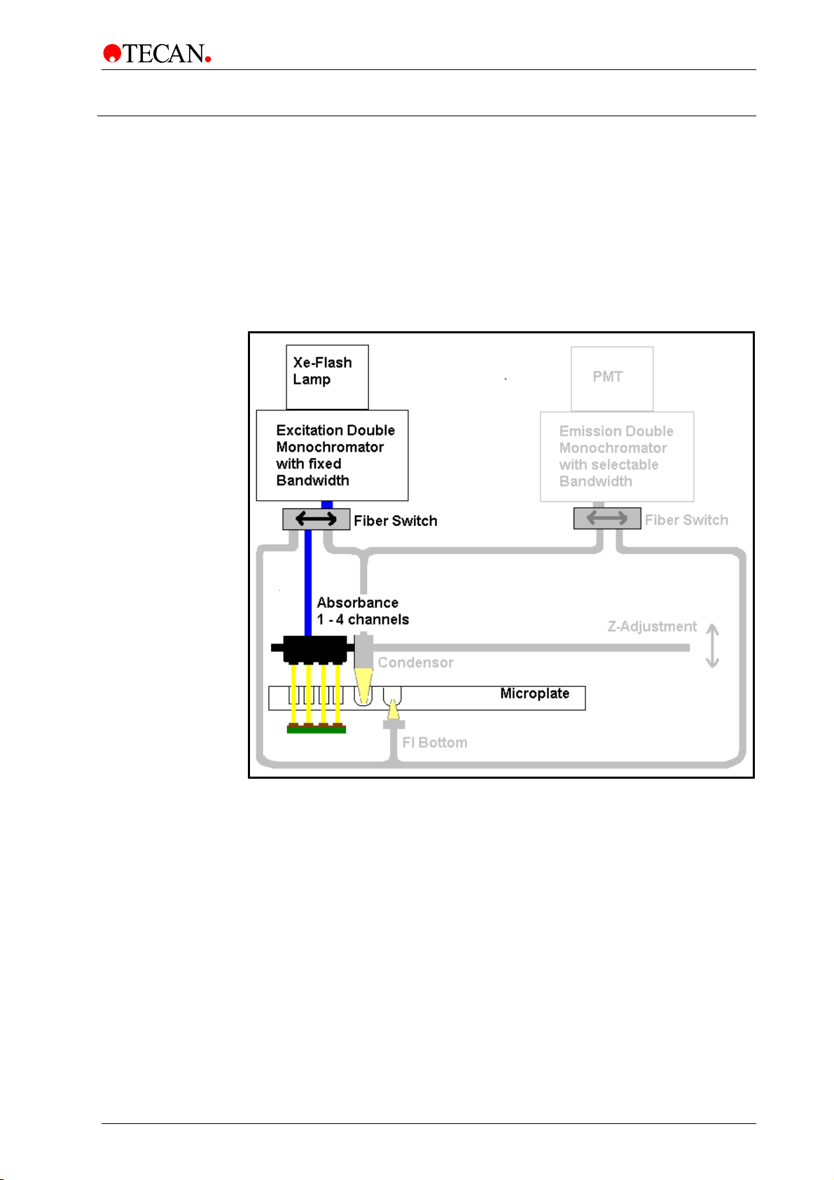
4.3 Absorbance System
For absorbance measurements, a similar optical path is used as for fluorescence
excitation. For details of the light source (1) and the excitation monochromator
(2), please refer to chapter 4.1.1 Light Source System Fluorescence Intensity.
A fiber bundl
absorbance optics (3), which focus the light into the wells. The transmitted light is
measured by silicon photodiodes (4) located beneath the plate carrier (see figure
below).
Before the measurement of the microplate is performed, a reference
measurement is made with the plate carrier moved away from the light beam.
e guides the light from the excitation monochromator (2) to the
1)
2)
3)
4)
Figure 17: Optical System Absorbance.
2011-09 Instructions for Use for INFINITE M1000 PRO No. 30064852 Rev. No. 1.0 41
Page 42
4. Optical System
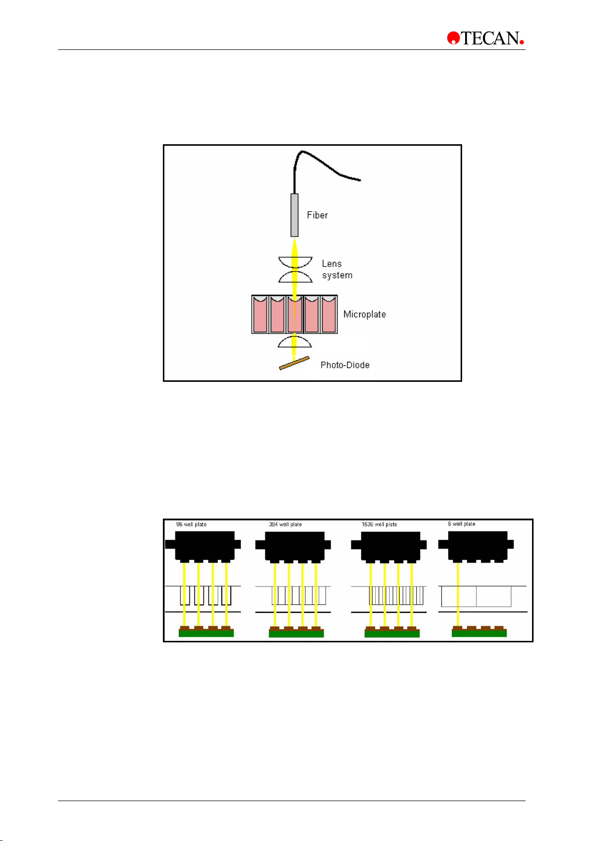
4.3.1 Absorbance Optics
Up to 4 fiber bundles guide the light from the excitation monochromator system to
the absorbance optics (Figure 17). The absorbance optics consist of a pair of
lenses
which focus the light beam into the well of the microplate (Figure 18).
Figure 18: Absorbance Optics, one channel.
The absorbance channels are spaced to read a 96-well plate. The optical
alignment for a 384 or 1536-well plate is shown in Figure 19.
The soft
well is measured with only one channel in absorbance mode. If a plate type other
than 96/384/1536 is used, only a single optic channel will be used for the
absorbance reading.
The light beam diameter of the absorbance optics is about 1 mm.
Measurements using the injector are performed with one absorbance channel
only.
Figure 19: From left to right: Schematic view of the channel usage of an
absorbance measurement of a 96, 384, 1536 and 6-well plate.
ware automatically sorts the data and reports it in the correct order. Each
42 Instructions for Use for INFINITE M1000 PRO No. 30064852 Rev. No. 1.0 2011-09
Page 43
4. Optical System
4.3.2 Absorbance Detection
A silicon photodiode is used for the measurement of the transmitted light. It is
sensitive to a wide range of wavelengths. The photodiode is well suited for the
light levels being encountered with absorbance measurements below 4 OD.
For absorbance measurement of nucleic acids in small volumes (2 µl)
use Tecan’s NanoQuant Plate. With this device it is possible to measure
16 different samples in one measurement.
For further information, please contact your local Tecan distributor or
visit: www.tecan.com.
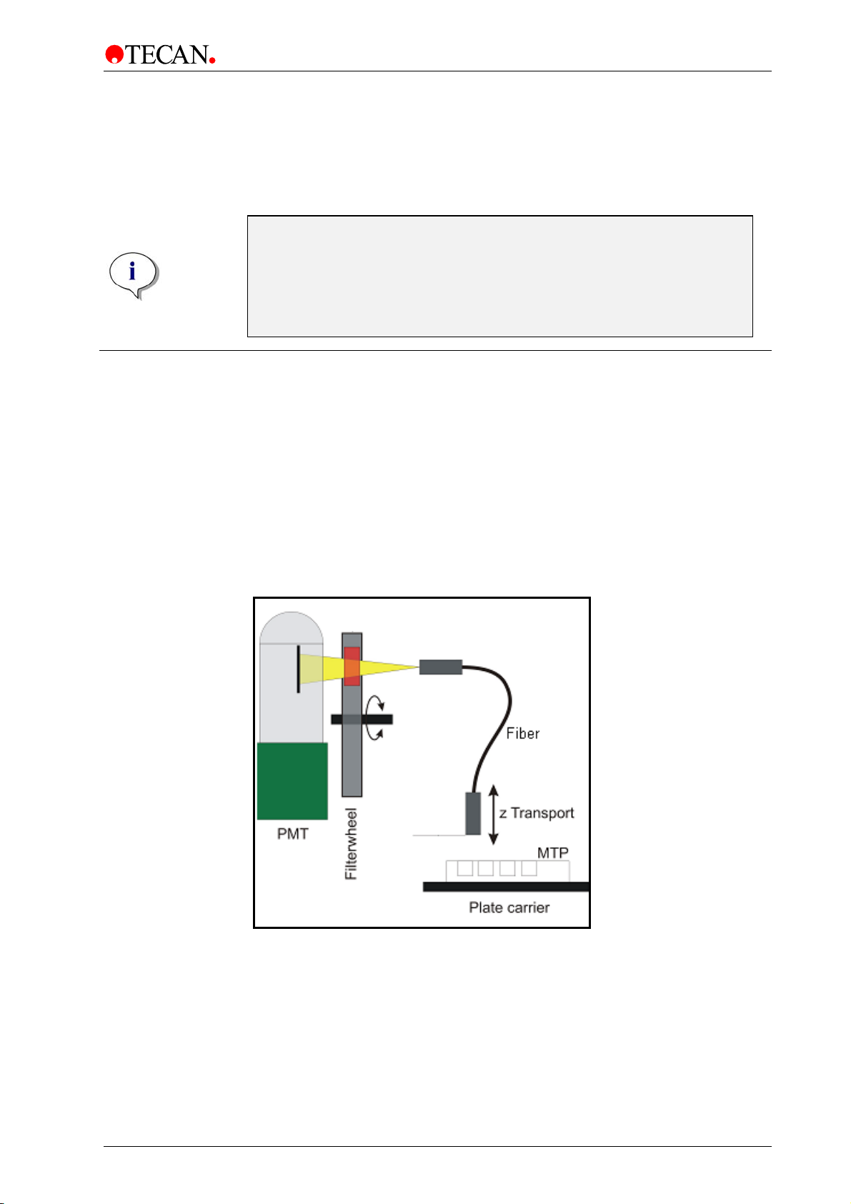
4.4 Luminescence System
For uncompromising performance, the INFINITE M1000 PRO has a dedicated
luminescence detection module. The luminescence optics have been
designed to meet requirements different from the dedicated fluorescence optics.
The much lower light levels involved when compared to flash lamp induced
fluorescence require the benefits of a photon counting detection technique.
The INFINITE M1000 PRO Luminescence System consists of the following parts
(see figure below): luminescence fiber bundle, the filter wheel, and detection unit
(PMT). The luminescence fiber bundle guides the light from the sample through
the filter wheel to the detector. Three different fibers are available for the
INFINITE M1000 PRO, the fibers are optimized for different plate types: 96, 384,
or 1536-well.
Note
Figure 20: Optical System Luminescence.
2011-09 Instructions for Use for INFINITE M1000 PRO No. 30064852 Rev. No. 1.0 43
Page 44

4. Optical System
4.4.1 Luminescence Optics
The Z-position of the luminescence fiber bundle can be adjusted. As light is
refracted onto the sample liquid surface, a Z-adjustment helps to maximize signal
to noise and minimize crosstalk. The software performs the adjustment
automatically, once the user has selected the corresponding plate type in the
software dialog box.
Fibers
A fiber guides the light from the sample to the detection unit. Three different fibers
are available for measuring 96, 384 or 1536-well plates.
The orifices in the ceiling of the measurement chamber are designed to receive
as much light as possible from the wells of 96, 384 or 1536-well plates, thus
maximizing the luminescence signal; however, the orifices do not receive
substantial amounts of light from neighboring wells, thereby minimizing crosstalk.
Filter Wheel
A filter wheel in front of the PMT window is switched to the required luminescence
filter channel. The sensitivity of the detection system makes it necessary to
attenuate high luminescence light levels, therefore the filter wheel is also able to
move a neutral density filter (OD2) across the selected fiber exit. This can be
done automatically in all wells that require attenuation by using the attenuation
setting “AUTOMATIC” in the instrument control software. The OD2 attenuation
cannot be manually selected for all measured wells.
Installed filters
• OD2 neutral density filter
2
• Green (Chroma-Glo, BRET
• Magenta (Chroma-Glo, BRET
• Blue 1 (BRET)
• Green 1 (BRET)
• Blue (BRET3)
• Orange (BRET3)
• AlphaScreen (not selectable for luminescence measurements)
• AlphaLISA (not selectable for luminescence measurements)
)
2
)
Note
The AlphaScreen and AlphaLISA filters installed in the filter wheel can
Figure 21 to Figure 26 show the transmission spectra of the different
lumine
44 Instructions for Use for INFINITE M1000 PRO No. 30064852 Rev. No. 1.0 2011-09
only be used for Alpha measurements, not for luminescence
measurements.
scence filters.
Page 45

4. Optical System
]
]
]
100
90
80
70
60
50
40
30
Transmi ssion [%
20
10
0
400 450 500 550 600 650
Wa ve le ngth [n m]
Figure 21: Transmission spectrum of filter ‘Lumi Magenta’.
Figure 22: Transmission spectrum of filter ‘Lumi Green’.
100
90
80
70
60
50
40
30
Transm ission [%
20
10
0
400 420 440 460 480 500 520 540 560
Wa ve le ng th [nm ]
Figure 23: Transmission spectrum of filter ‘Blue 1‘.
100
90
80
70
60
50
40
30
Transm issi on [%
20
10
0
450 470 490 510 530 550 570 590 610 630 650
Wa ve le ng th [nm ]
Figure 24: Transmission spectrum of filter ‘Green 1‘.
2011-09 Instructions for Use for INFINITE M1000 PRO No. 30064852 Rev. No. 1.0 45
Page 46

4. Optical System
]
]
100
90
80
70
60
50
40
30
Transmi ssion [%
20
10
0
460 490 520 550 580 610 640 670 700
Wavelength [nm]
Figure 25: Transmission spectrum of filter ‘Lumi Orange‘.
100
90
80
70
60
50
40
30
Transmissi on [%
20
10
0
400 430 460 490 520 550 580
Wa ve le ngth [nm ]
Figure 26: Transmission spectrum of filter ‘Lumi Blue‘.
Photon Counting Module (PCM)
The PCM, containing a channel photomultiplier, is designed for applications in
chemo- and bioluminescence. The channel photomultiplier provides a high
dynamic range enabling luminescence measurement with strong variations in
light levels. The exceptionally low noise and high sensitivity allow detection at
very low light levels.
4.4.2 Luminescence Detection
Caution
STOP
The INFINITE M1000 PRO luminescence detection system utilizes the single
photon counting measurement technique. This is based on a dedicated
luminescence PMT with appropriate measurement circuitry. This technique is
very robust against noise. It is preferred for measurements at very low light
levels.
For best performance, it is recommended to use white plates for luminescence
measurements.
Switch on the instrument at least 15 minutes before starting a
luminescence measurement to ensure stable conditions for the
measurement.
Note
The results of luminescence measurements are always displayed in
counts per second, regardless of the integration time used.
46 Instructions for Use for INFINITE M1000 PRO No. 30064852 Rev. No. 1.0 2011-09
Page 47

4. Optical System
4.5 AlphaScreen/AlphaLISA System
For uncompromised performance, the INFINITE M1000 PRO uses a dedicated
luminescence detection module (chapter 4.4 Luminescence System) for
AlphaScree
In addition to the Luminescence System, the INFINITE M1000 PRO uses a highpower laser as the excitation light source for AlphaScreen/AlphaLISA and a
contactless temperature sensor to measure the temperature inside each well.
4.5.1 AlphaScreen/AlphaLISA Optics
The Z-position of the luminescence fiber bundle can be adjusted. As light is
refracted onto the sample liquid surface, a Z-adjustment helps to maximize signal
to noise and minimize crosstalk. The software does the adjustment automatically,
once the user has selected the corresponding plate type in the software dialog
box.
Laser
The INFINITE M1000 PRO uses a high power laser (680 nm / 750 mW) as the
excitation light source.
The INFINITE M1000 PRO is a LASER CLASS 1 product. The INFINITE M1000
PRO complies with FDA radiation performance standards, 21 CFR 1040.10,
except for deviations pursuant to Laser Notice No. 50, dated June 24, 2007.
n/AlphaLISA measurements.
WARNING
LASER RADIATION – DO NOT STARE INTO THE BEAM!
CLASS IV LASER PRODUCT INSIDE.
2011-09 Instructions for Use for INFINITE M1000 PRO No. 30064852 Rev. No. 1.0 47
Page 48

4. Optical System
]
]
Fibers
A fiber guides the light from the sample to the detection unit. Three different fibers
are available for measuring 96, 384 or 1536-well plates.
The orifices in the ceiling of the measurement chamber are designed to receive
as much light as possible from the wells of 96, 384 or 1536-well plates, thus
maximizing the luminescence signal; however, the orifices do not receive
substantial amounts of light from neighboring wells, thereby minimizing crosstalk.
Filter Wheel
Two additional filters in the luminescence filter wheel allow for measurements of
AlphaScreen and AlphaLISA assays.
The transmission spectra of the AlphaScreen and AlphaLISA filters are shown in
figures 27 and 28.
100
90
80
70
60
50
40
30
Transmi ssion [%
20
10
0
500 530 560 590 620 650 680
Wave length [nm]
Figure 27: Transmission spectrum of filter ‘AlphaScreen’.
100
90
80
70
60
50
40
30
Transmi ssi on [%
20
10
0
500 530 560 590 620 650 680
Wavelength [nm]
Figure 28: Transmission spectrum of filter ‘AlphaLISA’.
Note
The luminescence attenuation and color filters installed in the filter
48 Instructions for Use for INFINITE M1000 PRO No. 30064852 Rev. No. 1.0 2011-09
wheel can only be used for luminescence measurements, not for
AlphaScreen/AlphaLISA measurements.
Page 49

4. Optical System
Photon Counting Module (PCM)
The PCM, which contains a channel photomultiplier, is designed for applications
in chemo- and bioluminescence. The channel photomultiplier provides a high
dynamic range, which enables luminescence measurements to be made even
with strong variations in light levels. The exceptionally low noise and high
sensitivity allow detection at very low light levels.
4.5.2 AlphaScreen/AlphaLISA Detection
Caution
STOP
The INFINITE M1000 PRO luminescence detection system utilizes the single
photon counting measurement technique. This is based on a dedicated
luminescence PMT with appropriate measurement circuitry. This technique is
very robust against noise and is, therefore, the preferred method for performing
measurements at very low light levels.
Switch on the instrument at least 15 minutes before starting a
luminescence measurement to ensure stable conditions for the
measurement.
Note
AlphaScreen/AlphaLISA measurements are only possible as endpoint
measurements in white or light gray microplates
The results of AlphaScreen/AlphaLISA measurements are always
displayed in counts per second, regardless of the integration time used.
and cannot be performed in combination
with the injector system or the heating system.
Note
4.5.3 AlphaScreen/AlphaLISA Temperature Correction
To compensate for the temperature sensitive nature of AlphaScreen/AlphaLISA
assays, the INFINITE M1000 PRO offers a unique temperature correction system
(optional):
A contactless temperature sensor measures the temperature inside each well
and the measured count rates are automatically normalized to a temperature of
22.5 °C.
Note
To ensure the best performance for AlphaScreen/AlphaLISA assays, the
INFINITE M1000 PRO should be operated in a temperature-regulated
environment (±1 °C in the range of 20–25 °C).
2011-09 Instructions for Use for INFINITE M1000 PRO No. 30064852 Rev. No. 1.0 49
Page 50

Page 51

5. Operating the INFINITE M1000 PRO
5. Operating the INFINITE M1000 PRO
5.1 Introduction
WARNING
BIOLOGICAL HAZARDS CAN BE ASSOCIATED WITH THE WASTE
MATERIAL (MICROPLATE) OF THE PROCESSES RUN ON THE INFINITE
M1000 PRO.
TREAT THE USED MICROPLATE, OTHER DISPOSABLES, AND ALL
SUBSTANCES USED, IN ACCORDANCE WITH GOOD LABORATORY
PRACTICE GUIDELINES.
INQUIRE ABOUT APPROPRIATE COLLECTING POINTS AND APPROVED
METHODS OF DISPOSAL IN YOUR COUNTRY, STATE OR REGION.
The INFINITE M1000 PRO is operated under personal computer-based software
control. i-control, Magellan, or EVOware software may be used as the user
interface. For details see the corresponding software manual. This chapter is for
a general understanding of instrument parameters and operation. Suggestions
are made about how to optimize instrument parameters for specific applications.
Every effort has been made to ensure that the instrument functions correctly even
if the default parameters are not appropriate for a particular application - with an
important exception: the selected plate definition file must correspond to the type
of plate used.
STOP
STOP
STOP
STOP
Caution
When placing a microplate into the plate carrier, always make sure that
the correct plate definition file (plate height) has been selected in the
software before you do anything else.
Maximum plate height is 23 mm including lid.
Caution
Before starting measurements, make sure that the microplate position
A1 is inserted correctly. The position of well A1 has to be on the upper
left side.
Important
When operating the INFINITE M1000 PRO always work
according to GLP (good laboratory practice) guidelines.
Caution
The INFINITE M1000 PRO has a fan on the rear of the instrument that
draws in air. The air filter must be checked every 4 weeks and must be
replaced when dirty. The air filter must be replaced after 6 months.
2011-09 Instructions for Use for INFINITE M1000 PRO No. 30064852 Rev. No. 1.0 51
Page 52

5. Operating the INFINITE M1000 PRO
5.2 General Operating Features
The INFINITE M1000 PRO has some general behavior and options, which are
independent of specifically selected measurement techniques.
5.2.1 Instrument Start Up
Before the instrument is switched ON, check if the USB interface cable is
connected.
Caution
When the USB interface cable is being plugged in or unplugged, the
STOP
instrument and the PC should be switched off.
It is highly recommended to only use the USB interface cable provided
Instrument Power On
When switching the instrument ON, no initialization steps are performed.
Connect to Instrument
When the software connects to the instrument, communication is established
between the instrument and the user interface. All movable parts (e.g. slits,
gratings, order sorting filter wheels, plate transport, z-transport) are initialized and
moved to the home position. The instrument is ready for operation.
When the software connects to the instrument, the functionality of the
STOP
by Tecan to ensure a good performance of the instrument.
Note
photo multiplier tube (PMT) is checked. This can take some time.
Caution
It is necessary to check the functionality of the PMT annually
using the MultiCheck-Plus test plate.
Loading Microplates
The INFINITE M1000 PRO is equipped with a ‘Retract/Eject’ button which allows
microplates to be inserted or removed from the instrument without software
activation.
52 Instructions for Use for INFINITE M1000 PRO No. 30064852 Rev. No. 1.0 2011-09
Page 53

5. Operating the INFINITE M1000 PRO
5.2.2 Finish a Measurement Session
Disconnect from Instrument
When disconnecting, communication between the instrument and the PC is
terminated.
Note
Remove the microplate before disconnecting.
Instrument Shut Down
Upon shut down, the instrument activity is stopped immediately. Normally, you
should disconnect before shutting down. In the rare case of an unexpected
hardware error, immediate instrument shut down will reduce the risk of possible
damage.
5.2.3 General Options
The following options can be combined with any measurement technique.
Temperature Control
Some assays ask for an exact operating temperature. The INFINITE M1000 PRO
can set up a specific temperature within a certain range, provide uniformity
across the plate, and keep the temperature constant above ambient. The main
cooling fans stop ventilation.
Temperature range: 4°C above ambient up to 42°C
Heating up the measurement chamber will take some time. Please check the
temperature control display. If not incubated externally, the microplate should be
left for equilibration before the measurement is started.
Kinetic Measurements
The i-control software allows a plate to be measured repeatedly in equidistant
time intervals. The fluorescence signal may significantly decrease over a longer
period of time, especially when using low volumes. Depending on the amount of
evaporation, the meniscus will shift to a lower position giving rise to slightly out of
focus conditions. Usually, wells in the corners evaporate faster.
Microplate Shaking
The INFINITE M1000 PRO is capable of plate shaking before the start of a
measurement or in between kinetic cycles. Three shaking modes are available:
linear, orbital and double orbital. The shaking amplitude can be selected from 1
to 6 mm in steps of 0.5 mm for linear and orbital shaking modes, and from 1 to
3.5 mm for double orbital shaking mode. The frequency is a function of the
amplitude. The shaking duration is selectable from 1-1000 s.
Multi-labeling
The i-control software provides a basic multi-labeling capability. Up to ten sets of
instrument parameters can be edited. The corresponding plate measurements
will be executed in order. For example, when using more than one fluorescent
label, different wavelength combinations can be selected.
2011-09 Instructions for Use for INFINITE M1000 PRO No. 30064852 Rev. No. 1.0 53
Page 54

5. Operating the INFINITE M1000 PRO
5.3 Optimize Fluorescence Measurements
Fluorescence measurement results may be improved by optimizing instrument
parameters and selecting the appropriate materials.
5.3.1 FI Scanning (Spectral Intensity Calibration)
Due to wavelength dependence on the intensity of the excitation light and
instrument components (gratings; lenses; PMT) being passed by the excitation
and emission light distortions of measured spectra might be possible.
Excitation spectra are distorted primarily by the wavelength dependence of the
intensity of the excitation light the INFINITE M1000 PRO allows you to correct the
spectra.
To calculate corrected emission spectra, one needs to know the wavelengthdependent efficiency of the detection system. Therefore a calibration curve is
saved on the INFINITE M1000 PRO for correction.
For more details see also‚ Principles of Fluorescence Spectroscopy’, Third
Edition; Joseph R. Lakowicz.
What is the reason for intensity differences between scan
measurement values and fixed wavelength measurement values?
Excitation scan versus fixed wavelength
The INFINITE M1000 PRO uses a reference fiber to compensate for fluctuations
of the flash lamp. The sensitivity of the reference fiber needs to be adjusted
(automatically done by the software) before each measurement to make sure that
the fiber is working in an optimal sensitivity range and does not show overflow
values. This reference measurement is performed differently for scan
measurements and fixed wavelength measurements. For fixed wavelength
measurements, the calibration of the reference fiber is performed at the selected
measurement wavelength.
For scan measurements, the same reference method would be possible. But in
the worst case (3D scan over full wavelength range) over 600 reference points
(one per wavelength) have to be measured and saved.
Depending on the number of measurement points, this can take a few seconds to
up to nearly one minute. To improve the measurement speed, we decided to
perform the reference measurement at one wavelength, which is expected to give
the highest light intensity. This procedure has proven successful in avoiding
overflow errors and in providing sufficient sensitivity. The fixed wavelength
measurement and scan measurement performed with the same measurement
parameters (gain, number of flashes, z-position), have one side effect the results
do not show the same RFU values.
Emission scan versus fixed wavelength
The reference measurement is performed at the selected excitation wavelength in
both modes. Fixed wavelength values might deviate from scan wavelength values
±10% due to energy fluctuations of the flash lamp.
54 Instructions for Use for INFINITE M1000 PRO No. 30064852 Rev. No. 1.0 2011-09
Page 55

5. Operating the INFINITE M1000 PRO
5.3.2 FP Measurements
Fluorescence Polarization
Fluorescence Polarization (FP) is defined by the following equation:
crosspar
II
−
P
G-Factor
=
II
+
par
I
perpendicular to the plane of excitation respectively. Polarization is a
dimensionless unit, generally expressed in mP units.
The given equation for calculation of fluorescence polarization assumes that the
sensitivity of the detection system is equivalent for parallel and perpendicular
polarized light. This is generally not the case and either the parallel or
perpendicular intensity must be corrected by a so-called “G-factor”. The G-factor
compensates for differences in optical components between parallel and
perpendicular measurement.
The G-factor is the correction factor that can be determined for the wavelength of
the fluorophore by measuring a sample with a known polarization value. A valid
calibration of the instrument resulting in a G-factor is an important requirement for
each FP measurement.
In order to perform a G-factor calibration, please define:
• Polarization reference: select a polarization value for the reference used,
• Reference blank: select all wells filled with blank. Select “same as
cross
and I
e.g. 20 mP for a 1nM fluorescein solution in 0.01 M NaOH. Select all wells
filled with fluorescein.
measurement blank” if the reference blank is the same as the sample blank.
equal the emission intensity of the polarized light parallel and
crosspar
Note
By filling in more than one well with polarization references and
reference blanks, the mean values will be calculated and therefore the
calibration result will be more accurate.
2011-09 Instructions for Use for INFINITE M1000 PRO No. 30064852 Rev. No. 1.0 55
Page 56

5. Operating the INFINITE M1000 PRO
Settle time
Due to the stop and go motion of the carrier, the dispensed liquid’s meniscus may
vibrate during signal integration. Vibrations can cause fluctuations in the
measured values, therefore to minimize this effect and to obtain optimal FP
performance, it is recommended to select a time between move and flash of
100ms.
Calculation of FP Parameters
G-factor:
cross
RFURFUP
−+
G
=
…Polarization value of reference
P
ref
RFU …Averaged relative fluorescence units of reference
ref
RFU …Averaged relative fluorescence units of buffer
buf
ref
ref
ref
par
ref
RFURFUP
−−
cross
buf
par
buf
))(1(
))(1(
Blank reduction:
The mean value of the respective blank wells is subtracted from each value.
par
buf
par
buf
par
blk
par
blk
RFU
par
⎧
⎪
⎪
⎪
=Δ
⎨
⎪
par
ref
par
buf
par
smp
−
RFURFU
−
RFURFU
−
RFURFU
⎪
⎪
⎩
blk
par
−
RFURFU
cross
ref
cross
buf
cross
smp
−
−
−
RFU
cross
⎧
⎪
⎪
⎪
=Δ
⎨
⎪
⎪
⎪
⎩
56 Instructions for Use for INFINITE M1000 PRO No. 30064852 Rev. No. 1.0 2011-09
cross
blk
−
cross
RFURFU
buf
cross
RFURFU
buf
cross
blk
cross
blk
RFURFU
RFURFU
Page 57

5. Operating the INFINITE M1000 PRO
Intensities:
Parallel and perpendicular intensities are calculated using the following formulas:
parpar
crosscross
crosspar
crosspar
II
RFUI Δ=
Polarization:
II
−
P
=
+
Anisotropy:
−
A
=
Total Intensity:
RFUGI Δ= *
crosspar
crosspar
II
II
*2+
crosspar
III
total
*2+=
5.3.3 Instrument Parameters
Gain Settings
The INFINITE M1000 PRO fluorescence detection system uses analog to digital
(A/D) conversion of the PMT signal. The gain setting controls the amplification of
the PMT when converting fluorescence light into electrical current. The A/D
converter needs a suitable input range of PMT current to provide the proper
signal to noise ratio (S/N) on the one hand, and linearity on the other hand.
Therefore, the gain should be optimized based on the wells with the highest
concentration give the highest possible readings. For best possible signal
resolution it is recommended to use the “Optimal Gain” setting.
If any well of interest is assigned “OVER” (overflow), you may manually
reduce the gain, or select an automatic gain option (see the software
Note
manual).
2011-09 Instructions for Use for INFINITE M1000 PRO No. 30064852 Rev. No. 1.0 57
Page 58
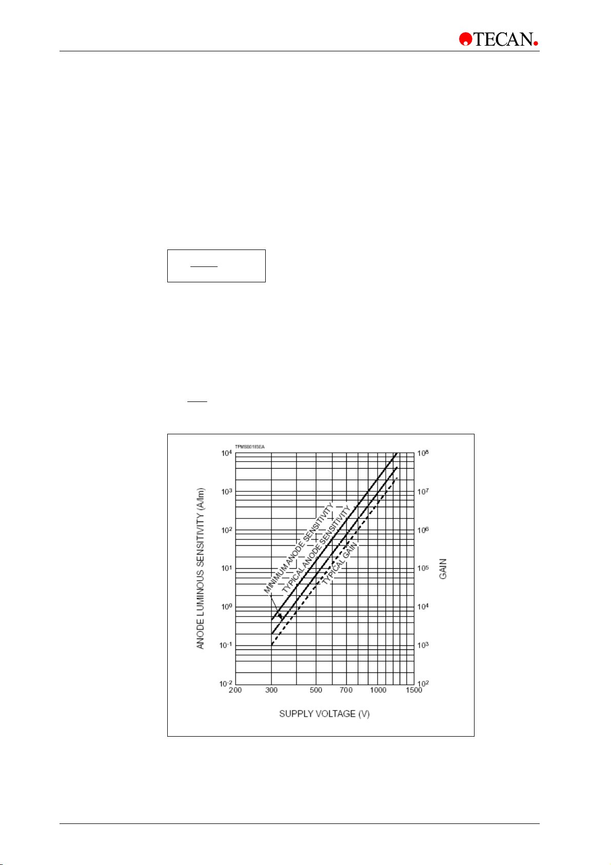
5. Operating the INFINITE M1000 PRO
Gain Adjustment
The gain for fluorescence intensity and polarization measurements is selectable
from 1 – 255. The performance of the PMT depends on the supply voltage (see
figure below). The INFINITE M1000 PRO PMT is specified from 300 to 1250 V.
The relationship between the gain setting of the INFINITE M1000 PRO and the
voltage supply is described in the equation below.
The intended use of the INFINITE M1000 PRO PMT is specified for gain settings
from 60 – 255. Gain settings below 60 are possible and might be useful for
special applications, but the performance of the PMT is not specified for voltage
supply < 300 V. Tecan, therefore, does not take responsibility for measurement
results of the INFINITE M1000 PRO when using gain settings below 60.
U =
Gain
V1250*
255
U Voltage
Gain INFINITE M1000 PRO gain
255 maximum gain on the INFINITE M1000 PRO
1250V maximum voltage supply of PMT
Example:
A gain of 100 corresponds to a voltage supply of 490 V:
U ==
100
255
V4901250*
Figure 29: Sensitivity of PMT in relation to supply voltage.
Sensitivity below 300 V is not specified.
58 Instructions for Use for INFINITE M1000 PRO No. 30064852 Rev. No. 1.0 2011-09
Page 59
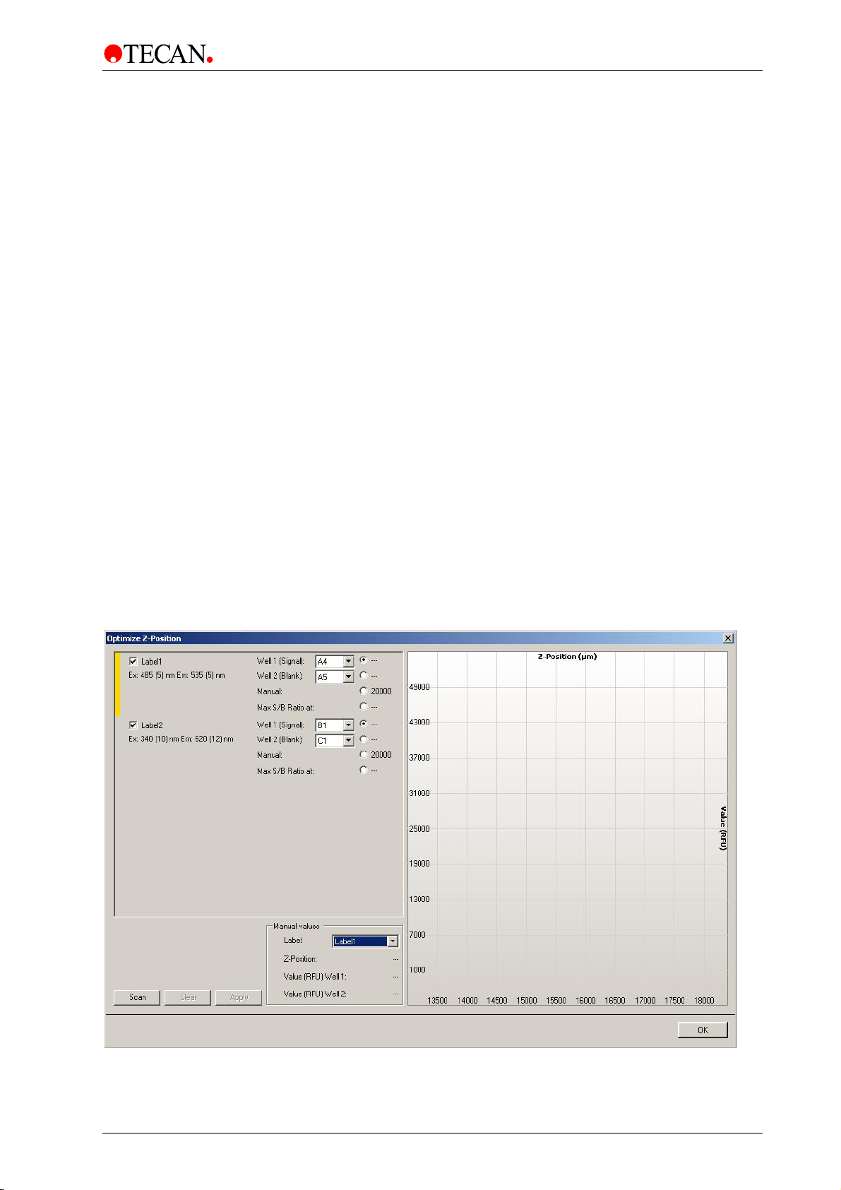
5. Operating the INFINITE M1000 PRO
Z-Optimization
Z-optimization is only available for FI Top and FP measurements with the
INFINITE M1000 PRO. For a particular assay, this procedure should be
performed once to determine the optimum working distance between the sample
in the plate and the fluorescence optics.
The z-position can be determined as follows:
(1) ‘Manual’:
When using the ‘manual’ option, a numeric z-position value can be entered in the
measurement stripe.
(2) ‘Calculated from well’:
When using the option ‘calculated from well’, the INFINITE M1000 PRO will
automatically identify the z-position of maximum signal in the selected well for
further measurements.
(3) ‘Same as’ for multi-labeling measurements:
When using the ‘same as’ option, the INFINITE M1000 PRO will automatically
use the same z-position as for a previously defined label, e.g. in a script with 2 FI
Top labels named as Label 1 and Label 2 the z-positionof Label 1 can also be
used for Label 2 by selecting the option‘Same as = Label 1’.
Select ‘Z-Position’ from the Instrument menu:
When using the ‘Z-position’ function in the instrument menu, the user can
determine the appropriate z-position from a graphical plot that shows the well(s)
used for z-positioning. The selected value is applied for further measurements.
Select the label(s) for which the z-position optimization is to be performed. The
optimal z-position can be simultaneously determined for up to 5 labels. The label
selection/number of labels depends on the measurement script previously
defined in i-control.
Figure 30
2011-09 Instructions for Use for INFINITE M1000 PRO No. 30064852 Rev. No. 1.0 59
Page 60

5. Operating the INFINITE M1000 PRO
For each selected label, one or two wells of the defined plate range can be used
for the z-position optimization. Select the well(s) and click ‘Scan’ to start the zoptimization: The z-positioning option ‘Max S/B Ratio’ requires the measurement
of two wells, one filled with the fluorophore of interest (signal) and one filled with
buffer (blank). Both wells are scanned and the resulting signal and blank curves
are shown in the graph. The z-position may now be set to the maximum signalto-blank (S/B) ratio.
Figure 31
Note
When the option ‘Max S/B Ratio’ is used, the sample well is first
measured with optimal gain and the very same gain value is then
applied to the second measurement with the blank well. Therefore, both
signal and blank curves are directly comparable.
The z-position for each selected label can be defined manually. The vertical
yellow bar of the graph can be moved to the desired z-position. Upon clicking
‘Apply’, the selected z-position will be automatically applied to i-control script
and used for the subsequent measurement.
60 Instructions for Use for INFINITE M1000 PRO No. 30064852 Rev. No. 1.0 2011-09
Page 61

5. Operating the INFINITE M1000 PRO
Flash Settings
On the fly measurements with 1 flash per well are possible for all plate types.
However, measurement precision at low light levels depends on the length of the
reading time during which a fluorescence signal can be received. For prompt
fluorescence, it does not help to increase the default integration time, because
the detector will not receive more signal once the flash has vanished.
Increase the number of flashes per well until noise of BLANK wells does
not improve further, or until the measurement time per well becomes
Flash Frequency Mode
The INFINITE M1000 PRO allows switching between two flash frequencies for
the Fluorescence Intensity and Fluorescence Intensity Scan mode: 100 and
400 Hz (100/400 flashes per second). As a standard, it is recommended to use
the 400 Hz mode and 50 flashes. A higher number of flashes, and therefore a
higher number of single measurement values, results in more accurate final
measurement values.
For time resolved fluorescence (TRF) measurements we recommend using the
100 Hz mode to improve results.
Note
unacceptable.
Timing Parameters for Time Resolved Fluorescence
For TRF, signal integration parameters need to be adjusted according to the
label. The start of the signal Integration Time is delayed by the Lag Time of the
preceding flash. TRF timing parameters may be established with the following
procedure:
1) As a starting point, take, for example, the Fluorescence Lifetime of the
label for both Integration Time and Lag Time.
2) Coarse tuning: With the Integration Time fixed, reduce the Lag Time to
maximize Signal to Background (S/B).
3) Fine tuning: With the Lag Time fixed, extend the Integration Time and
check if S/B improves further.
4) Optional Fine-tuning: With one timing parameter fixed, vary the other one
and check if S/B improves further.
A comparison of S/B with different timing parameters is valid if gain is fixed. For
dual TRF labels, establish the procedure for the label with the shorter
fluorescence lifetime (label 1). Compromise the Integration Time of label 1 with
the Lag Time of label 2.
2011-09 Instructions for Use for INFINITE M1000 PRO No. 30064852 Rev. No. 1.0 61
Page 62

5. Operating the INFINITE M1000 PRO
Time between Move and Flash
When selecting more than one flash per well, a time delay between move and
flash can be set. Due to the stop and go motion of the plate carrier, the meniscus
of the dispensed liquid may vibrate while signal is integrated. This can give rise to
fluctuations of the measured values. The effect has been observed in the wells of
96-well plates and also in larger wells. In particular, it is critical with absorbance
measurements.
5.3.4 FI Ratio Mode
Ratio Mode
Up to 5 labels can be measured well-wise. This measurement mode is called
‘ratio mode’. Be aware that no ‘ratio’ calculation is performed after this
measurement. The Excel result sheet shows the raw data. Further calculations
must be performed by the user.
5.3.5 Optimal Read (FI Bottom Measurements Only)
The "Optimal Read" function is available for Fluorescence Bottom
measurements only. The "Optimal Read" function is a measurement on multiple,
spatially-separated spots inside the well. The spots are arrayed to cover the
whole well area in order to achieve maximum well illumination. The total number
of individual measurement spots per well is reflected by the size of the beam
diameter of the Fluorescence Intensity Bottom fiber and is optimized for plate
formats from 12 to 96 wells (see table below).
Plate Pattern Number of Spots
1536-well ‘Optimal Read’ option not available
384-well ‘Optimal Read’ option not available
96-well Circle (filled) 5
48-well Circle (filled) 21
24-well Circle (filled) 37
12-well Circle (filled) 61
6-well ‘Optimal Read’ option not available
“Optimal Read” spot patterns in different plate formats
The flash number per measurement spot is selectable via the software
(1-200 flashes) and the number of measurement spots per well is displayed as
soon as the ‘Optimal Read’ function is activated for a certain plate format in the
fluorescence bottom measurement stripe. The ‘Optimal Read’ function is
available in combination with the 400 Hz flash frequency mode only.
The user-defined ‘total number of flashes’ is automatically distributed over all
measured spots per well. A minor imprecision occurs if an entered flash number
is not divisible without a remainder by the default number of spots for the plate
format used. In this case, the next possible flash distribution that is integrally
divisible by the number of spots per well is calculated, e.g. a measurement with a
total of 26-30 flashes in a 96-well plate (5 single spots) is performed with
6 flashes per spot, whereas a total flash number of 31 results in 7 flashes per
spot.
62 Instructions for Use for INFINITE M1000 PRO No. 30064852 Rev. No. 1.0 2011-09
Page 63
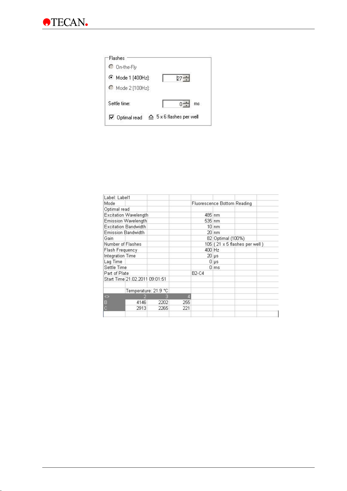
5. Operating the INFINITE M1000 PRO
Figure 32
Result Display in MS Excel
The MS Excel results sheet generated by i-control software displays a single
average measurement value for each well that has been measured using the
Optimal Read function. The employed Optimal Read settings, i.e. the overall
number of flashes as well as the number of flashes per well, are also displayed.
Figure 33 Results output for a measurement with optimal read (example for a 48well plate).
Miscellaneous Features of Optimal Read
Optimal Read is only available for Fluorescence Intensity Bottom measurements.
The Optimal Read feature is not available when performing well-wise
measurements. The standard MRW function for Fluorescence Intensity Bottom
reads is disabled when “Optimal Read” is activated and vice-versa. The Optimal
Read feature is not available in combination with the gain setting extended
dynamic range.
2011-09 Instructions for Use for INFINITE M1000 PRO No. 30064852 Rev. No. 1.0 63
Page 64

5. Operating the INFINITE M1000 PRO
5.3.6 Measurement Accessories
Recommended Types of Microplates
Generally, for high fluorescence sensitivity, black microplates are recommended.
For low concentrations of TRF labels, white microplates seem superior. You may
check if white plates are superior with UV excitation wavelengths.
With its z-Positioning capability, the INFINITE M1000 PRO can optimize signal for
a particular volume of dispensed sample. However, we do not recommend using
volumes less than a third of the maximum volume. When using lower volumes,
check the availability of a suitable plate type.
5.4 Optimize Absorbance Measurements
5.4.1 Measurement Parameters
Flash Settings
‘On-the-fly’ measurements with 1 flash per well are possible for all plate types,
however, measurement precision at low light levels depends on the reading time
while fluorescence signal can be received.
The 400 Hz flash frequency mode is available for Absorbance measurements
only. By increasing the number of flashes more accurate results can be achieved.
Increase the number of flashes per well until noise of BLANK wells does
not further improve, or until measurement time per well becomes
Time between Move and Flash
When selecting more than one flash per well, a time delay between move and
flash can be set (100-300 ms). Due to the stop and go motion of the plate carrier,
the meniscus of the dispensed liquid may vibrate while signal is integrated. This
can give rise to fluctuations of the measured values. The effect has been
observed in the wells of 96-well plates and also in larger wells.
Note
unacceptable.
64 Instructions for Use for INFINITE M1000 PRO No. 30064852 Rev. No. 1.0 2011-09
Page 65

5. Operating the INFINITE M1000 PRO
5.4.2 Absorbance Ratio Mode
Ratio Mode
When using the “Standard” tab in i-control, up to 5 labels can be measured wellwise. This measurement mode is called ‘ratio mode’. Be aware that no ‘ratio’
calculation is performed after this measurement. The Excel result sheet shows
the raw data; further calculations must be performed by the user.
When using the “Applications” tab in i-control together with the NanoQuant Plate,
the raw data for “Quantifying Nucleic Acids” and “Labeling Efficiency” are all
automatically calculated for concentration or ratio-calculation by Excel software.
The values can be used for further calculation if preferred.
5.4.3 Measurement Accessories
Recommended Types of Microplates
Generally, for absorbance measurements, transparent or UV-transparent
microplates are used. For high OD values, black microplates with transparent
bottoms seem superior.
Note
For absorbance measurements of nucleic acids in small volumes (2 µl),
use Tecan’s NanoQuant PlateTM. With this device it is possible to
measure 16 different samples in one measurement.
For further information, please contact your local Tecan distributor or
visit: www.tecan.com.
5.5 Optimize Luminescence Measurements
5.5.1 Integration Time
At very low light levels, a PMT does not yield a continuous output current, which
is necessary for a reliable analog to digital conversion, but instead a sequence of
pulses are produced, the average rate of which can be measured using a
counter. The advantage of using the photon counting technique at such low light
levels is that pulse height selection criteria allow much of the electronic noise to
be filtered out.
At very low light levels, the measured counts per second are proportional to the
light intensity. Increasing the measurement time per well yields more accurate
values because of the irregular photon impact (photon statistics). The photonic
noise (shot noise) cannot be reduced further by technical means.
Note
The relevant signal to (shot) noise ratio can be improved by a factor
when measurement time is multiplied with the square of the desired
factor.
Note
If a luminescence measurement results in an INVALID
in one or more wells because the measured signal was too high,
2011-09 Instructions for Use for INFINITE M1000 PRO No. 30064852 Rev. No. 1.0 65
the Luminescence PMT may need a certain amount of time
to return to the equilibrium baseline count level.
 Loading...