

Page 1
Instructions for Use for
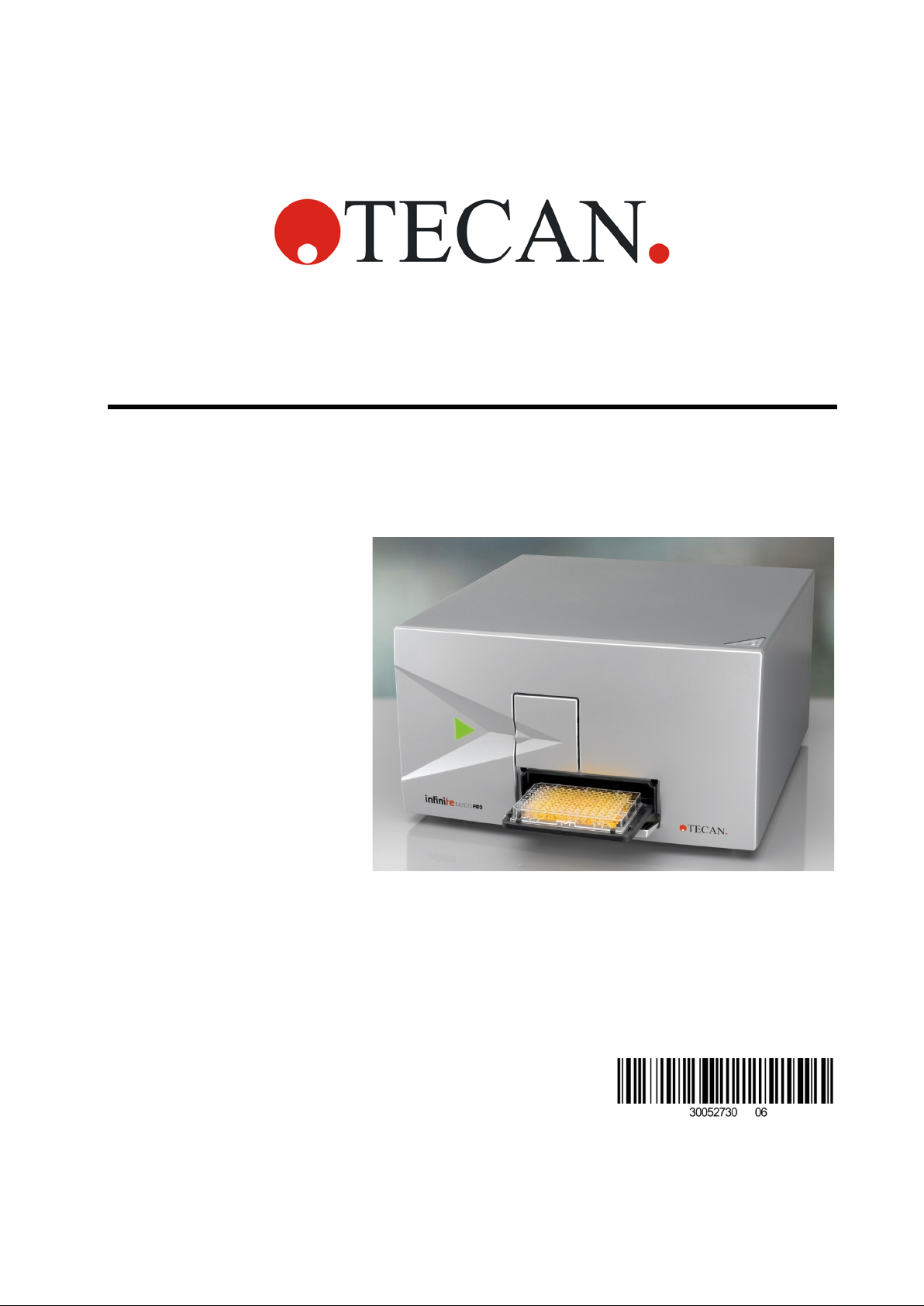
Infinite 200 PRO
Document Part No.: 30052730
2016-04
Document Revision No.: 1.6
Page 2

WARNING
CAREFULLY READ AND FOLLOW THE INSTRUCTIONS PROVIDED
IN THIS DOCUMENT BEFORE OPERATING THE INSTRUMENT.
Notice
Every effort has been made to avoid errors in text and diagrams; however, Tecan
Austria GmbH assumes no responsibility for any errors, which may appear in this
publication.
It is the policy of Tecan Austria GmbH to improve products as new techniques
and components become available. Tecan Austria GmbH therefore reserves the
right to change specifications at any time with appropriate valid ation, ver if icatio n,
and approvals.
We would appreciate any comments on this publication.
Manufacturer
Tecan Austria GmbH
Untersbergstr. 1A
A-5082 Grödig, Austria
T +43 62 46 89 33
F +43 62 46 72 770
E-mail: office.austria@tecan.com
www.tecan.com
Copyright Information
The contents of this document are the property of Tecan Austria GmbH and are
not to be copied, reproduced or transferred to another person or persons without
prior written permission.
Copyright Tecan Austria GmbH
All rights reserved.
Printed in Austria
Declaration for EU Certificate
See the last page of these Instructions for Use.
About the Instructions for Use
Original Instructions. This document describes the Infin ite 200 PRO
multifunctional microplate reader. It is intended as reference and instructions for
use. This document instructs how to:
• Install the instrument
• Operate the instrument
• Clean and maintain the instrument
2 IFU for Infinite 200 PRO No. 30052730 Rev. No. 1.6 2016-04
Page 3
Remarks on Screenshots
The version number displayed in screenshots may not always be the one of the
currently released version. Screenshots are replaced only if content related to
application has changed.
Trademarks
The following product names and an y registered and unr eg ister ed tr ademarks
mentioned in this document are used for identification purposes only and remain
the exclusive property of their respective owners:
®,
• Infinite
and the Tecan Logo are registered trademarks of
Tecan Group Ltd., Männedorf, Switzerland
• Windows
Redmond, WA, USA
• ChromaGlo
Promega Corporation Madison, WI, USA
• Starna
Road, Hainault, Essex IG6 3UT England, United Kingdom
• BRET2
registered trademarks of PerkinElmer, Inc., Waltham, Massachusetts, USA
i-controlTM, GCMTM, magellanTM, NanoQuant PlateTM,Tecan®
®
and Excel® are registered trademarks of Microsoft Corporation,
TM
Dual-Luciferase® and Enliten® are registered trademarks of
®
is a registered trademark of Starna Scientific Limited, 52-54 Fowler
TM
, DeepBlueC®, PerkinElmer®, AlphaScreen® and AlphaLISA® are
Warnings, Cautions, and Notes
The following types of notices are used in this publication to highlight important
information or to warn the user of a potentially dangerous situation:
Gives helpful information.
CAUTION
INDICATES A POSSI B ILITY OF INSTRUMENT DAMAGE OR DATA LOSS
INDICATES T HE POSSIBILITY OF SEVERE PERSONAL INJURY,
LOSS OF LIFE OR EQUIPMENT DAMAGE IF THE INSTRUCTIONS
THIS SYMBOL INDICATES THE POSSIBLE PR ESENCE OF
BIOLOGICALLY HAZARDOUS MATERIAL. PROPER LABORATORY
IF INSTRUCTIONS ARE NOT FOLLOWED.
WARNING
ARE NOT FOLLO WED.
WARNING
SAFETY PRECAUTIONS MUST BE OBSERVED.
Note
2016-04 IFU for Infinite 200 PRO No. 30052730 Rev. No. 1.6 3
Page 4

WARNING
THIS SYMBOL INDICATES THE POSSIBLE PR ESENCE OF
FLAMMABLE MA TERIALS AND A RISK OF FIRE. PROPER
LABORATORY SAFETY PRECAUTIONS MUST BE OBSERVED.
ATTENTION
NEGATIVE E NVIRONMENTAL IMPACTS ASSOCIA TE D WITH THE
TREATMENT O F W ASTE.
DO NOT TREAT ELECTRICAL AND ELECTRONIC EQUIPMENT
AS UNSORTED MUNICIPAL WASTE.
COLLECT WASTE ELECTRIC AL AND ELECTRONIC
EQUIPMENT SEPARATELY.
Symbols
Manufactured by
Date of manufacture
Conformité Européenne
Read the Instructions for Use
before operating the instrument
Order number
Serial Number
USB label
WEEE symbol
RoHS Orange Logo
TÜV NRTL
4 IFU for Infinite 200 PRO No. 30052730 Rev. No. 1.6 2016-04
Page 5

Table of Contents
1. Safety ................................................................................................................. 9
1.1 Instrument Safety ................................................................................. 9
2. General Description ........................................................................................ 11
2.1 Instrument ........................................................................................... 11
2.1.1 Intended Use ........................................................................................ 11
2.1.2 Multifunctionality ................................................................................... 12
2.1.3 Performance ......................................................................................... 13
2.1.4 User Friendliness ................................................................................. 13
2.1.5 Onboard Control Button ....................................................................... 13
2.1.6 Rear View ............................................................................................. 14
2.2 Software .............................................................................................. 15
2.3 Injectors (Optional) ............................................................................ 15
2.3.1 Injector Measurem ent M odes ............................................................... 15
2.3.2 Injector Module Diagram ...................................................................... 16
2.3.3 Injector Pump Options .......................................................................... 16
2.3.4 Storage Bottles and Bottle Holders ...................................................... 17
2.3.5 Injector Carrier ..................................................................................... 18
2.4 Measurement Techniques ................................................................. 20
2.4.1 Fluorescence ........................................................................................ 20
2.4.2 Absorbance .......................................................................................... 22
2.4.3 Luminescence ...................................................................................... 23
2.4.4 AlphaScreen/AlphaLISA ....................................................................... 23
2.5 Optical System ................................................................................... 24
2.5.1 Fluorescence Intensity System (Infinite M200 PRO) ............................ 24
2.5.2 Fluorescence Intensity System (Infinite F200 PRO) ............................. 30
2.5.3 Fluorescence Polarization System (Infinite F200 PRO) ....................... 34
2.5.4 Absorbance System (Infinite F200 PRO) ............................................. 35
2.5.5 Absorbance System (Infi ni te M2 00 PR O) ............................................. 37
2.5.6 Luminescence System ......................................................................... 39
2.5.7 Cuvette Port (Infinite M200 PRO) ......................................................... 42
2.5.8 AlphaScreen/AlphaLISA System (Infinite F200 PRO only) ................... 45
3. Installation ....................................................................................................... 47
3.1 Unpacking and Inspection ................................................................. 47
3.1.1 Unpacking Procedure ........................................................................... 48
3.2 Removal of the Transport Locks....................................................... 49
3.3 Transport and Storage ....................................................................... 50
3.3.1 Transport .............................................................................................. 50
3.3.2 Storage ................................................................................................. 50
3.4 Power Requirements .......................................................................... 51
3.5 Switching the Instrument On ............................................................ 52
4. Gas Control Module (Enhanced) ................................................................... 53
2016-04 IFU for Infinite 200 PRO No. 30052730 Rev. No. 1.6 5
Page 6

4.1 Safety ................................................................................................... 53
4.2 Gas Control Module Features............................................................ 54
4.2.1 Gas Control Module Configurations ...................................................... 54
4.2.2 Top and Rear Views of the Gas Control Module .................................. 55
4.3 Main Menu of Modes .......................................................................... 57
4.3.1 CO2 Mode ............................................................................................ 57
4.3.2 O2 Mode ............................................................................................... 58
4.3.3 DUAL Mode .......................................................................................... 59
4.3.4 Manual Mode ........................................................................................ 60
4.4 Settings Menu ..................................................................................... 61
4.5 Installing the Gas Control Module .................................................... 62
4.5.1 Requirements ....................................................................................... 62
4.5.2 Installation Procedure ........................................................................... 63
4.6 Operating the Gas Control Module ................................................... 67
4.7 CO2 and N2 Gas Cylinders (Not Supplied Accessory) ..................... 71
4.8 Troubleshooting the Gas Control Module ........................................ 72
5. Operating the Instrument ............................................................................... 75
5.1 Introduction......................................................................................... 75
5.2 General Operating Features .............................................................. 76
5.2.1 Instrument Start Up .............................................................................. 76
5.3 General Options .................................................................................. 76
5.4 Defining Filter Slides (Infinite F200 PRO only) ................................. 78
5.4.1 About Filters ......................................................................................... 78
5.4.2 Filter Slide and Filter Orientation .......................................................... 78
5.4.3 Installing a Custom Filter ...................................................................... 80
5.4.4 Defining the Filters ................................................................................ 83
5.5 Optimizing Fluorescence Measurements ......................................... 87
5.5.1 Instrument Parameters ......................................................................... 87
5.5.2 Z-Optimization (FI Top measurements with the Infinite M200 PRO only)88
5.5.3 FI Ratio Mode ....................................................................................... 93
5.5.4 Optimal Read........................................................................................ 94
5.6 FP Measurements ............................................................................... 96
5.6.1 Fluorescence Polarization .................................................................... 96
5.6.2 Measurement Blank Range .................................................................. 96
5.6.3 G-Factor Settings ................................................................................. 97
5.6.4 Measurement with an Uncali br ate d G-Factor ....................................... 97
5.6.5 Measurement with a Simultaneous G-Factor Cali br ati on ..................... 98
5.6.6 Measurement with a Cali br ated G-Factor ............................................. 99
5.6.7 Measurement with a Manual G-Factor ............................................... 100
5.6.8 Calculation of Fluorescence Polarizat ion Para meters ........................ 101
5.7 Optimizing Absorbance Measurements ......................................... 102
5.7.1 Measurement Parameters .................................................................. 102
6 IFU for Infinite 200 PRO No. 30052730 Rev. No. 1.6 2016-04
Page 7

5.7.2 Absorbance Ratio Mode ..................................................................... 102
5.8 Multiple Reads per Well ................................................................... 103
5.8.1 MRW Type ......................................................................................... 103
5.8.2 MRW Size .......................................................................................... 104
5.8.3 MRW Border ...................................................................................... 104
5.8.4 Result Display in MS Excel ................................................................ 106
5.8.5 Miscellaneous Software Features of MRW ........................................ 106
5.9 Optimizing Luminescence Measurements ..................................... 107
5.9.1 Integration Time ................................................................................. 107
5.9.2 Light Level Attenuation ....................................................................... 107
5.10 Optim i z i ng AlphaScreen/AlphaLISA Measurements ..................... 108
5.10.1 Instrument Parameters ....................................................................... 108
5.11 Measurements with Injectors .......................................................... 110
5.11.1 Priming and Washing of the Infinite 200 PRO .................................... 110
5.11.2 Washing ............................................................................................. 114
5.11.3 Before Starting a Measurement with Injectors .................................... 118
5.11.4 Injector Modes (i-control) .................................................................... 118
5.12 Bla nking Measurements .................................................................. 123
5.13 Cuvette Measurements .................................................................... 124
5.13.1 Cuvette Strip ...................................................................................... 124
5.13.2 Cuvette Movements ........................................................................... 124
5.13.3 i-control Cuvette Examples ................................................................ 125
5.14 i-control Examples ........................................................................... 129
5.15 Fini shing a Measurement Session .................................................. 133
5.15.1 Disconnecting the Instrument ............................................................. 133
5.15.2 Instrument Shut Down ........................................................................ 133
6. Instrument Features ..................................................................................... 135
6.1 Introduction ...................................................................................... 135
6.2 Instrument Specifications ............................................................... 136
6.3 Fluorescence Intensity and Time Resolved Fluorescence (TRF). 138
6.3.1 Definition of the Detection Limit .......................................................... 139
6.3.2 Fluorescein (Fluorescence Intensity) Top .......................................... 139
6.3.3 Fluorescein (Fluorescence Intensity) Bottom ..................................... 139
6.3.4 Europium (Time Resolved Fluorescence) .......................................... 139
6.4 Fluorescence Polarization (FP) ....................................................... 140
6.5 Absorbance ...................................................................................... 141
6.6 Glow Type Luminescence ............................................................... 142
6.6.1 ATP Glow Luminescence ................................................................... 142
6.7 Flash Type Luminescence ............................................................... 143
6.8 Dual Color Luminescence (e.g. BRET) ........................................... 144
6.9 AlphaScreen/AlphaLISA .................................................................. 144
6.10 “On the Fly” Measurements ............................................................ 145
2016-04 IFU for Infinite 200 PRO No. 30052730 Rev. No. 1.6 7
Page 8

6.11 Cuvette Features (Infinite M200 PRO only) ..................................... 146
6.11.1 Cuvette Specifications ........................................................................ 146
6.12 Injector Specifications ..................................................................... 147
6.12.1 Injector Reagent Compatibility ............................................................ 147
6.13 Measurement Accessories .............................................................. 148
6.13.1 Recommended Filters (Infinite F200 PRO only) ................................. 148
6.13.2 Recommended Types of Microplates ................................................. 149
6.13.3 Luminescence Detection .................................................................... 153
7. Quality Control .............................................................................................. 155
7.1 Periodic Quality Control Tests ........................................................ 155
7.2 Specifications - Passed/Failed Criteria ........................................... 156
7.3 Specifications - Test Instructions ................................................... 157
7.3.1 Fluorescence Top ............................................................................... 157
7.3.2 Fluorescence Bottom .......................................................................... 161
7.3.3 Time Resolved Fluorescence ............................................................. 165
7.3.4 Fluorescence Polarization (Infinite F200 PRO only) ........................... 167
7.3.5 Glow Luminescence ........................................................................... 169
7.3.6 Absorbance Accuracy ......................................................................... 170
7.3.7 Absorbance Wavelength Accuracy ..................................................... 170
7.3.8 Absorbance Baseline Flatness (Infinite M200 PRO)........................... 171
7.3.9 Absorbance Baseline F l atness (I nfi ni te F20 0 PR O) ........................... 172
7.3.10 Absorbance Cuvette (Infinite M200 PRO only) ................................... 173
7.3.11 AlphaScreen/AlphaLISA (Infinite F200 PRO only) .............................. 174
8. Cleaning and Maintenance ........................................................................... 177
8.1 Introduction....................................................................................... 177
8.2 Liquid Spills ...................................................................................... 178
8.3 Injector Cleaning and Maintenance ................................................ 178
8.3.1 Daily Maintenance: ............................................................................. 179
8.3.2 Weekly/Periodical Maintenance:......................................................... 179
8.4 Instrument Disinfection ................................................................... 180
8.4.1 Disinfection Solutio ns ......................................................................... 180
8.4.2 Disinfection Proced ur e ....................................................................... 181
8.4.3 Safety Certificate ................................................................................ 181
8.4.4 Disposal .............................................................................................. 182
8.4.5 Disposal of Packing Material .............................................................. 182
8.4.6 Disposal of Operating M at eri al ........................................................... 182
8.4.7 Disposal of the Instrument .................................................................. 183
9. Troubleshooting ............................................................................................ 185
Index ....................................................................................................................... 189
8 IFU for Infinite 200 PRO No. 30052730 Rev. No. 1.6 2016-04
Page 9

1. Safety
1. Safety
1.1 Instrument Safety
1. Always follow basic safety precautions when using this product to reduce
the risk of injury, fire, or electrical shock.
2. Read and understand all information in the Instructions for Use. Failure to
read, understand, and follow the instructions in this document may result
in damage to the product, injury to operating personnel or poor
instrument performance.
3. Observe all WARNING and CAUTION statements in this document.
4. Never open the housing of the Infinite 200 PRO while the instrument is
plugged into a power source.
5. Never force a microplate into the instrument.
6. The Infinite 200 PRO is intended as a general purpose laboratory
instrument for professional use. Observe proper laboratory safety
precautions, such as wearing protective clothing and using approved
laboratory safety procedures.
STOP
CAUTION
TECAN AUSTRIA GMBH HAS TAKEN GREAT CARE IN CREATING THE
STORED PLATE DEFINITION FILES THAT ARE RECEIVED WITH THE
INSTRUMENT SOFTWARE.
WE HAVE TAKEN EVERY PRECAUTION TO ENSURE THAT THE PLATE
HEIGHTS AND WELL DEPTHS ARE CORRECT ACCORDING TO THE DEFINED
PLATE TYPE. THIS PARAMETER IS USED TO DETERMINE THE MINIMUM
DISTANCE BETWEEN THE TOP OF THE PLATE AND THE CEILING OF THE
MEASUREMENT CHAMBER. ADDITIONALLY, TECAN AUSTR IA HAS ADD E D A
VERY SMALL SAFETY GAP TO PREVENT ANY DAMAGE OCCURRING TO THE
MEASUREMENT CHAMBER AS A RESULT OF SMALL CHANGES IN PLATE
HEIGHT. THIS DOES NOT AFFECT THE PERFORMANCE OF THE
INSTRUMENT.
USERS MUST ENSURE THAT THE PLATE DEFINITION FILE SELECTED
CORRESPONDS TO THE ACTUAL PLATE BEING USED.
USERS SHOULD ALSO TAKE CARE THAT NO POTENTIAL FLUORESCENT
OR LUMINESCENT CONTAMINATION LIES ON TOP OF THE PLATE. BE
AWARE THAT SOME PLATE SEALERS LEAVE BEHIND A STICKY RESIDUE
THAT MUST BE COMPLETELY REMOVED BEFORE STARTING
MEASUREMENTS.
CAUTION
STOP
BEFORE STARTING MEASUREMENTS, MAKE SURE THAT THE MICROPLATE
POSITION A1 IS INSERTED CORRECTLY. THE POSITION OF WELL A1 HAS
TO BE ON THE UPPER LEFT SIDE.
CAUTION
STOP
2016-04 IFU for Infinite 200 PRO No. 30052730 Rev. No. 1.6 9
TO INSURE THE OPTIMAL WORKING OF TECAN INSTRUMENTS
WE RECOMMEND A SER VICE INTERVAL OF 6 MONTHS.
Page 10

1. Safety
It is assumed that the instrument operators, because of their vocational
experience, are familiar with the necessary safety precautions for handling
chemicals and biohazardous substances.
Adhere to the following laws and guidelines:
1. National industrial protection law
2. Accident prevention regulations
3. Safety data sheets of the reagent manufacturers
WARNING
DEPENDING ON THE AP PLICA TIONS, PARTS OF THE INFINITE 200
PRO MAY COME IN CONTACT WITH BIOHAZARDOUS/INFECTIOUS
MATERIAL. MAKE SURE THAT ONLY QUALIFIED PERSONNEL
OPERATE THE INSTRUMENT. IN CASE OF SERVICE OR WHEN
RELOCATING OR DISPOSING OF THE INSTRUMENT, ALWAYS
DISINFECT THE INSTRUMENT ACCORDING TO THE
INSTRUCTIONS GIVEN IN THIS MANUAL.
10 IFU for Infinite 200 PRO No. 30052730 Rev. No. 1.6 2016-04
Page 11
2. General Description
2. General Description
2.1 Instrument
The Tecan Infinite 200 PRO is a multifunctional microplate reader with injec tor
option. The Infinite 200 PRO provides high performance for the vast majority of
today’s microplate applications and research and is robotic compatible.
2.1.1 Intended Use
The Infinite 200 PRO has been designed as a general purpose laboratory
instrument for professional use, supporting common 6 to 384-well microplates
conforming to the ANSI/SBS standards (see 6.13.2 Recommended Types of
Microplates for further details).
Note
System Validation by Operating Au th o rity is required. The Infinite 200
PRO has been validated on a selected set of assays only. It is the
responsibility of any operating authority to ensure that the Infinite 200
PRO has been validated for every specific assay used on the
instrument.
WARNING
LIMITATION:
WHEN USING THE GAS MODULE OPTION TO MEASURE AND
CONTROL OXYGEN LEVELS, THE INSTRUMENT IS INTENDED FOR
RESEARCH USE ONLY - NOT FOR USE IN DIAGNOSTIC
WHEN OXYGEN LEVELS ARE NOT MEASURED OR CONTROLLED, THE
INSTRUMENT IS INTENDED FOR USE AS A GENERAL PURPOSE
LABORATORY INSTRUMENT FOR PROFESSIONAL USE.
PROCEDURES.
2016-04 IFU for Infinite 200 PRO No. 30052730 Rev. No. 1.6 11
Page 12

2. General Description
2.1.2 Multifunctionality
Depending on the mode of wavelength selection, the Infinite 200 PRO is
available in two different versions:
Infinite M200 PRO
Infinite F200 PRO
The following measurement techniques are supported by the Infinite M200 PRO:
Fluorescence Intensity (FI) Top
Fluorescence Intensity (FI) Bottom
Time-Resolved Fluorescence (TRF)
Fluorescence Resonance Energy Transfer (FRET)
Flash Fluorescence (with injectors)
Absorbance
Absorbance (with injectors)
Absorbance in cuvettes
Glow Luminescence
Flash Luminescence
Bioluminescence Resonance Energy Transfer (BRET)
A fully-equipped Infinite F200 PRO supports the following measurement
techniques:
Fluorescence Intensity (FI) Top
Fluorescence Intensity (FI) Bottom
Time-Resolved Fluorescence (TRF)
Fluorescence Resonance Energy Transfer (FRET)
Time-Resolved Fluorescence Resonance Energy Transfer (TR-FRET)
Flash Fluorescence (with injectors)
Fluorescence Polarization (FP)
Absorbance
Absorbance (with injectors)
Glow Luminescence
Flash Luminescence
Bioluminescence Resonance Energy Transfer (BRET)
AlphaScreen/AlphaLISA
Any common microplate ranging from 6 to 384 well formats conforming to the
ANSI/SBS standards (ANSI/SBS 1-2004; ANSI/SBS 2-2004, ANSI/SBS 3-2004
and ANSI/SBS 4-2004) may be measured with any of the above measurement
techniques. Switching between measurement techniques or plate formats is fully
automated via software. It is not necessary to manually reconfigure the optics in
order to switch between the reading modes supported by the Infinite 200 PRO.
Both instrument versions, the filter-based Infinite F200 PRO and the
monochromator-based Infinite M200 PRO, may be equipped with up to two
injectors.
12 IFU for Infinite 200 PRO No. 30052730 Rev. No. 1.6 2016-04
Page 13
2. General Description
2.1.3 Performance
The Infinite 200 PRO has been designed to meet the requirements of a generalpurpose laboratory instrum ent.
The Infinite 200 PRO provides a range of parameters for optimizing the
measurement results according to: the assay type (cell-based or homogeneous),
the microplate type, and the dispensed volumes per well and dispensing speeds.
2.1.4 User Friendliness
The Infinite M200 PRO offers unparalleled flexibility in wavelength selection for
fluorescence intensity and absorbance measurements. Via software any
wavelength can be easily adjus ted within the specified wavelength range. In
addition to single wavelength measurements, absorbance and fluorescence
spectra can be recorded. When running a spectrum there is no restriction due to
cut-off filters .
The Infinite F200 PRO offers high flexibility for the customization of fluorescence
and absorbance measurements; slides containing fluorescence and absorbance
interference filters are easily accessible to the user.
If the instructions given in this do cument are not correctly performed,
the instrument will either be dam aged or the procedures will not be
performed correctly and the safety of the instrument is not guaranteed.
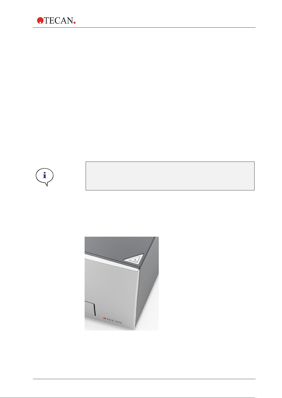
2.1.5 Onboard Control Button
The Infinite 200 PRO possesses an onboard control button to control plate
movements without the need to be connected to the software. Upon pressing the
‘Plate In/Out’ button, the current position of the plate carrier is automatically
recognized and the plate is moved into or out of the instrument.
Note
Figure 1: Onboard of the Infinite 200 PRO. The ‘Plate In/Out’ button is located in the front
right corner of the top cover.
2016-04 IFU for Infinite 200 PRO No. 30052730 Rev. No. 1.6 13
Page 14
2. General Description
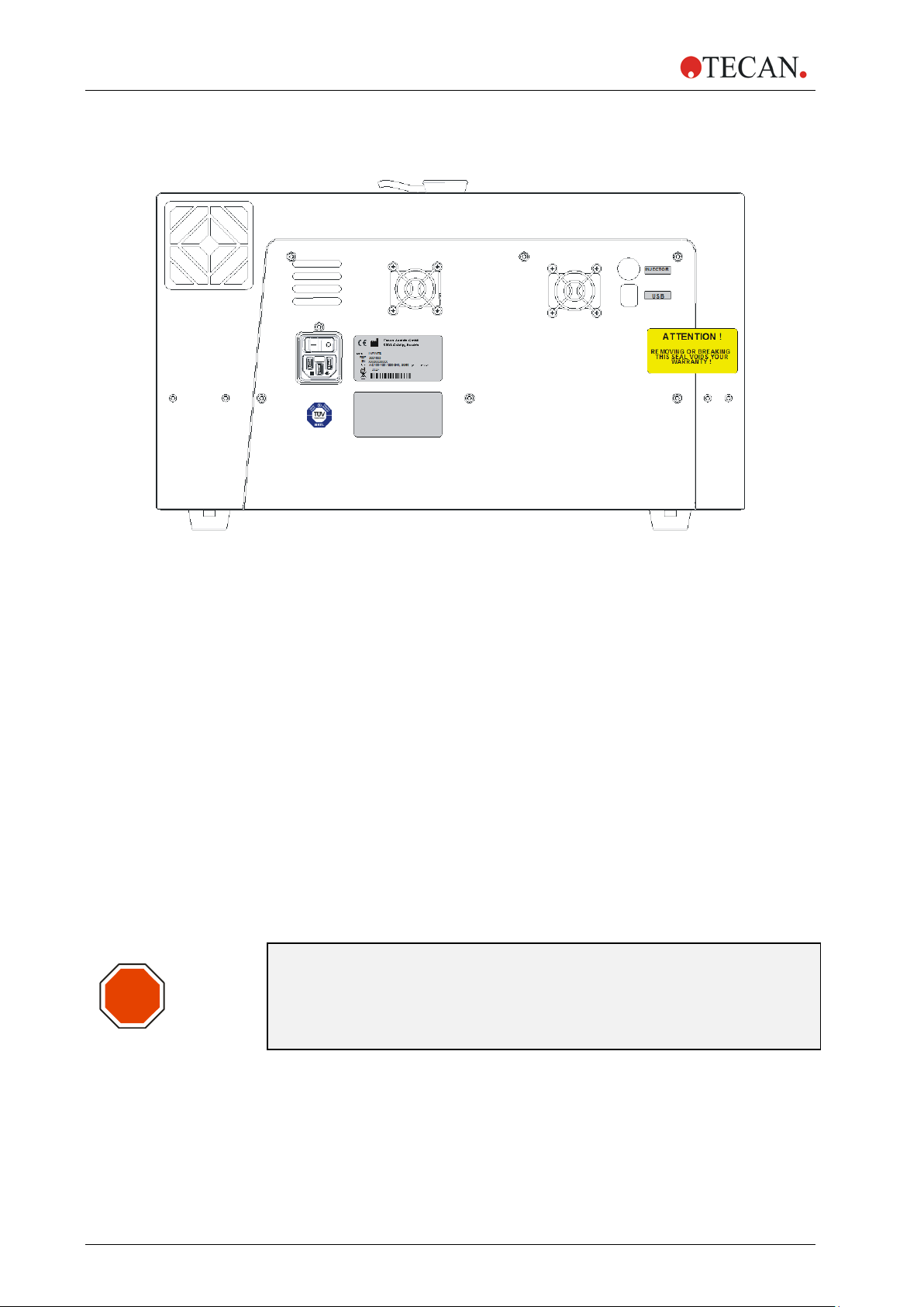
2.1.6 Rear View
Figure 2: Rear panel
STOP
1 Instrument Fan
2 Main Power Switch
3 Main Power Socket
4 Label – RoHS Orange Logo
5 Label – Technical Inspection Agency (TÜV)
6 Power Supply Fan
7 Name Plate
8 Label – Options/Configuration
9 Injector Connection
10 USB Connection
“ATTENTION
11 Warranty Label:
REMOVING OR BREAKING
THIS SEAL VOIDS
WARRANTY!”
CAUTION
ONLY TECAN AUTHORIZED SERVICE TECHNICIANS ARE ALLOWED
TO OPEN THE INSTRUMENT. REMOVING OR BREAKING THE
WARRANTY SEAL VOIDS THE WARRANTY.
14 IFU for Infinite 200 PRO No. 30052730 Rev. No. 1.6 2016-04
Page 15
2. General Description
2.2 Software
The Infinite 200 PRO is delivered with the i-control software, for operating the
instrument and includes an online-help file and a printed Instructions for Use. The
software is formatted as a self-extracting archive on CD-ROM. (For information
about the system requirements, refer to the Instructions for Use for the i-control
software. The Instructions for Use for the i-control can be found on the software
CD.)
For advanced data reduction, the Magellan software can be used to control the
Infinite 200 PRO. Magellan offers all functionality for compliance with the FDA
regulation 21 CFR part 11 for electronic records and signatures (for more
information, contact your local Tecan representative).
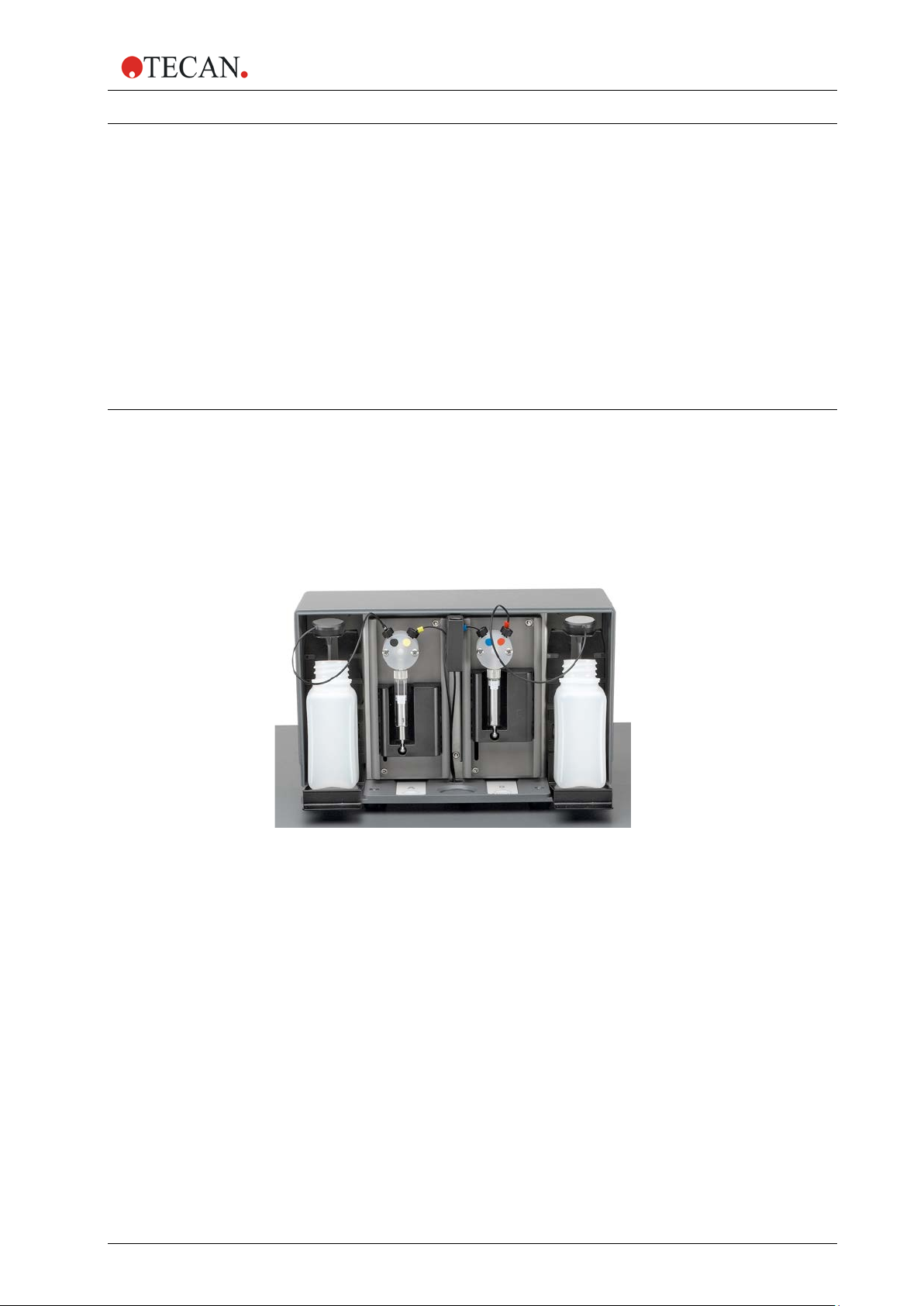
2.3 Injectors (Optional)
The Infinite 200 PRO can be optionally equipped with an injector module
consisting of one or two syringe pumps (XE-1000, Tecan Systems) located in a
separate box, which feed one or two injector needles.
The injector needles are designed to inject liquid in any SBS-conform microplate
well types, in which the well-size is equal to or larger than an SBS standard 384well plate.
Figure 3: Injector-box with bottle holders
2.3.1 Injector Measurement Modes
The injectors of the Inf in ite 200 PRO can be used with the following measurement
modes:
• Fluorescence Intensit y top and bottom
• Time Resolved Fluorescence
• Absorbance
• Flash Luminescence
• Glow Luminescence
• Dual Color Luminescence
As the measurement position is not the same as the injector position, a short time
delay (approx. < 0.5 s) between injection and reading occurs.
For details on how to set up a measurement with injectors, please refer to chapter
5.10.5 Injector.
2016-04 IFU for Infinite 200 PRO No. 30052730 Rev. No. 1.6 15
Page 16
2. General Description
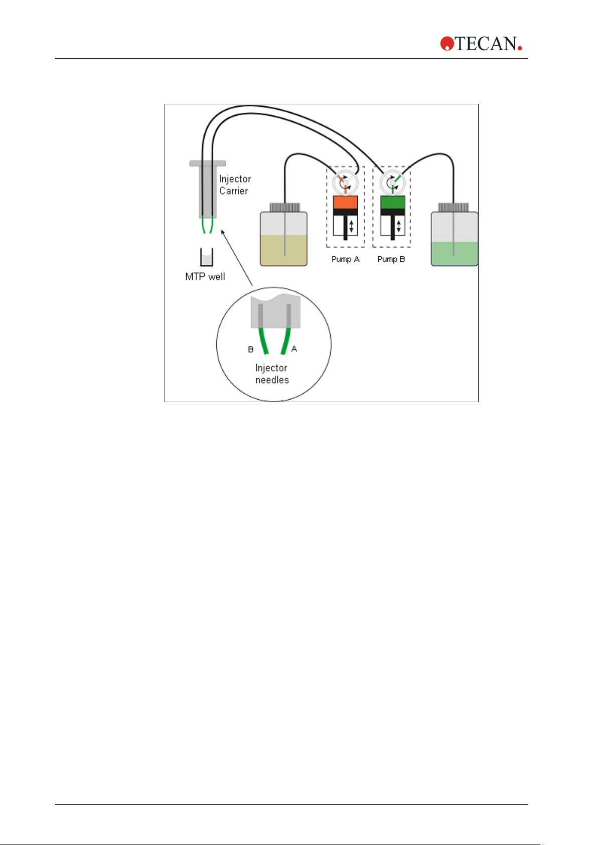
2.3.2 Injector Module Diagram
Figure 4: Schematic view of the injector module
2.3.3 Injector Pump Options
There are up to two pumps available for the Infinite 200 PRO (see Figure 4
above):
• Pump A feeds injector needle A
• Pump B feeds injector needle B
The Infinite 200 PRO can be equipped with one pump (pump A) or two pumps
(pumps A and B):
• One Injector Option (one pump): An Infinite 200 PRO equipped with one
pump allows injections in any SBS-conform microplate well types, in which
the well-size is equal to or larger than an SBS standard 384-well plate.
• Two Injector Option (two pumps): Some applications, such as flash
luminescence reactions or dual reporter gene assays require the injection of
two independent liquids into the same well; therefore, Tecan Austria offers a
two-injector option.
16 IFU for Infinite 200 PRO No. 30052730 Rev. No. 1.6 2016-04
Page 17
2. General Description
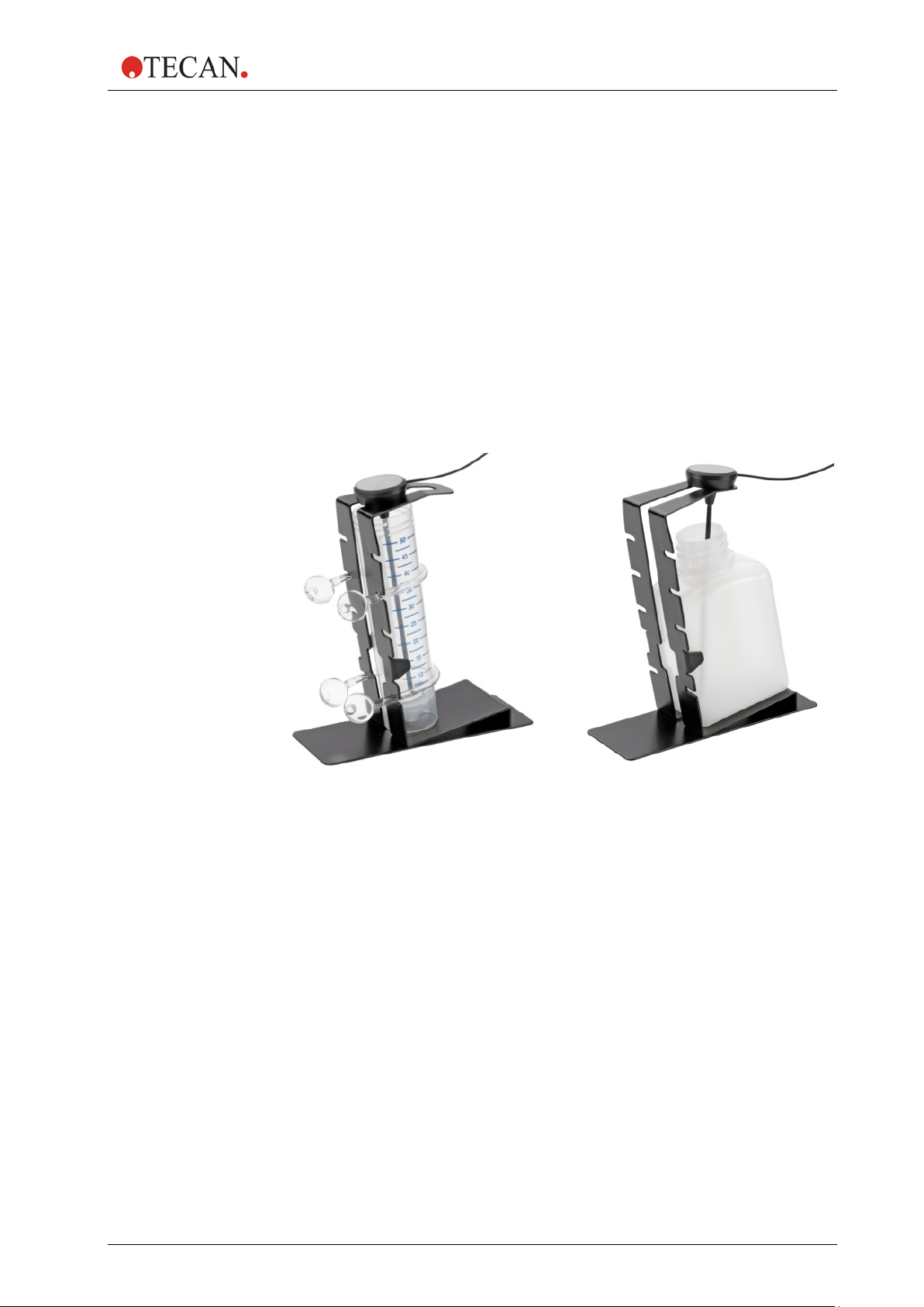
2.3.4 Storage Bottles and Bottle Holders
The injector box can accommodate up to two 125 ml bottles.
The standard bottle set supplied with the Injector option consists of:
• One 125 ml bottle and one 15 ml bottle for the “One Injector option”
(one pump) or
• One 125 ml bottles and two 15 ml bottles for the “Two Injectors option”
(two pumps).
The injector option includes up to two bottle holders that are designed for tubes of
different sizes and volumes. The bottles and tubes containing the fluids that are
to be injected can be attached securely to the holder using flexible PVC clasps.
The tubes from the injector syringe can be inserted into a carbon needle reaching
down to the bottom of the flask to ensure the optimal aspiration of even small
volumes of fluid.
Figure 5: Bottle holders
2016-04 IFU for Infinite 200 PRO No. 30052730 Rev. No. 1.6 17
Page 18
2. General Description
2.3.5 Injector Carrier
The injector carrier, whic h i nclud es the injector needles, can be easily removed
from the instrument for priming or washing the system and for optimizing the
injection speed.
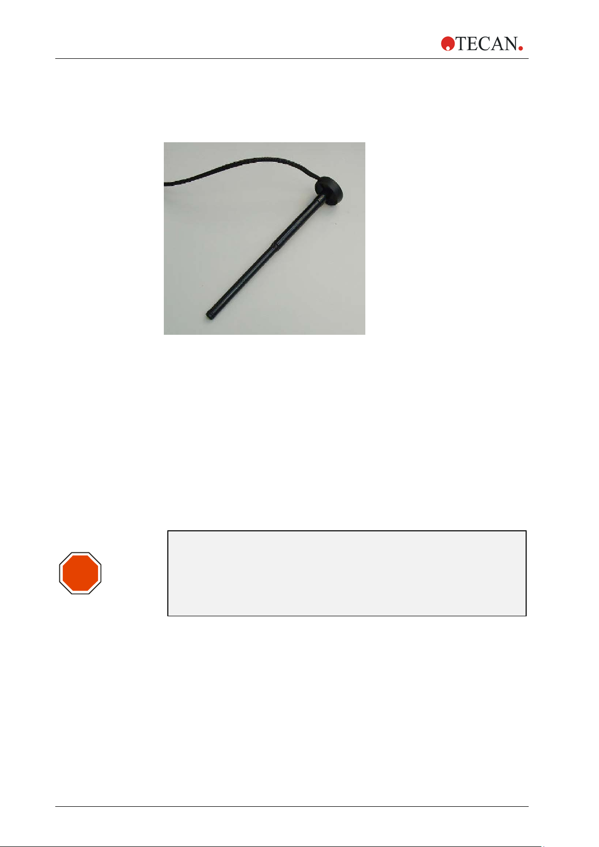
Figure 6: Injector carrier
STOP
When using the injector during a measurement or for just dispensing a plate the
injector carrier must be inserted correctly into the instrument. Remove the injector
dummy and insert the carrier into the injector port. Press the carrier softly into the
injector port until you hear a clicking noise.
The instrument contains an injector sensor that checks that the position of the
injector carrier for the actions ‘inject’ and ‘dispense’ is correct.
If the injector carrier is not inserted correctly, the injector sensor does not
recognize the inserted carrier and neither dispensing nor injection is possible.
On the other hand, actions like washing and priming are enabled although the
injector carrier is inserted; therefore, always make sure that the injector carrier is
in the service position for washing and priming.
CAUTION
THE INJECTOR CARRIER MUST BE IN THE SERVICE POSITION
FOR WASHING UND PRIMING.
PRIME AND WASH MUST NOT BE PERFORMED
WHEN THE INJECTOR IS IN THE INSTRUMENT!
18 IFU for Infinite 200 PRO No. 30052730 Rev. No. 1.6 2016-04
Page 19

2. General Description
STOP
Figure 7: Inserting the injector carrier into the injector port
CAUTION
IF THE INJECTOR CARRIER IS NOT INSERTED CORRECTLY IN THE
INJECTOR PORT, THE INJECTOR SENSOR WILL NOT DETECT THE
INSERTED INJECTOR AND THEREFORE WASHING AND PRIMING
WILL BE ENABLED, WHICH CAN DAMAGE THE INSTRUMENT.
2016-04 IFU for Infinite 200 PRO No. 30052730 Rev. No. 1.6 19
Page 20

2. General Description
2.4 Measurement Techniques
The following sections provide an introduction to the Inf inite 200 PRO
measurement techniques when fully equipped. To keep this compact, a few
simplifications have been made. For details see the references.
2.4.1 Fluorescence
The Infinite 200 PRO offers the basic fluorescence measurement technique and
some even more sophisticated variants:
• Fluorescence Intensit y (FI) (or simply Fluorescence)
• Fluorescence Resonance Energy Transfer (FRET)
• Fluorescence Time Resolved (TRF)
• Fluorescence Polarization (FP)
FI may also be used to measure Fluorescence Resonance Energy Transfer
(FRET). For some microplate applications, FRET offers advantages over FI and
TRF, because they simplify assay preparation. These preferably apply for mix
and measure binding studies. Compared to FP, FRET requires both binding
partners to be label ed in a suitab le way. On the other hand, FRET may utilize
TRF labels for increased sensitivity, then being referenced as HTRF
(Homogeneous TRF).
TRF should not be confused with Fluorescence Lifetime measurements.
Fluorescent molecules emit light of specific wavelength when struck by light of
shorter wavelength (Stokes Shift). In particular, a single fluorescent molecule can
contribute one fluorescence photon (quantum of light). This is a part of the
energy, which has been absorbed before (electronic excitation), but could not be
released quickly enough into thermal energy.
The average time it takes between excitation and emission is called the
fluorescence lifetime. For many fluorescent molecular species, fluorescence
lifetime is on the order of nanoseconds (prompt fluorescence). After excitation,
fluorescence emission occurs with a certain probability (quantum yield), which
depends on the fluorescent species and its environmental conditions.
For a detailed treatise on fluorescence techniques and applications see:
Principles of Fluorescence Spectroscopy by Joseph R. Lakowicz, Plenum
Press.
A) Fluorescence Intensity (FI)
In many microplate applications, the intensity of fluorescence emission is
measured to determine the abundance of fluorescent labeled compounds. In
these assays, other factors having an influence on fluorescence emission need to
be controlled experimentally. Temperature, pH-value, dissolved oxygen, kind of
solvent etc. may significantly affect the fluorescence quantum yield and therefore
the measurement results.
20 IFU for Infinite 200 PRO No. 30052730 Rev. No. 1.6 2016-04
Page 21

2. General Description
B) Fluorescence Resonance Energy Transfer (FRET)
Some microplate applications utilize a sophisticated dual labeling strategy. The
FRET effect enables you to measure how many of two differently labeled
compounds are in close proximity. This makes it suitable for binding studies.
Basically, FRET is a fluorescence intensity measurement of one of the two
fluorescent labels (acceptor). However, the acceptor is not susceptible to the
excitation wavelength of the light source being used. Instead, the acceptor may
receive excitation energy from the other fluorescent label (donor), if both are
spatially close together. As a prerequisite, the excitation wavelength has to apply
to the donor. Secondly, the emission spectrum of the donor has to overlap the
excitation spectrum of the acceptor (resonance condition). Nevertheless, the
transfer of excitation energy from donor to the acceptor is radiation free.
Some FRET-based applications utilize suitable pairs from the fluorescent protein
family, like GFP/YFP (Green/Yellow Fluorescent Protein, (ref. Using GFP in
FRET-based applications by Brian A. Pollok and Roger Heim – trends in Cell
Biology [Vol.9] February 1999). Overview is given in the Review Article –
Application of Fluorescence R eso n ance Energy Transfer in the Clinical
Laboratory: Routine and Research by J. Szöllösi, et al. in Cytometry 34, page
159-179 (1998).
Other FRET-based applications take advantage from using TRF labels as the
donor. For example see, High Throughput Screening – Marcel Dekker Inc.
1997, New York, Basel, Hong Kong, section 19 Homogeneous, Time-Resolved
Fluorescence Method for Drug Discovery by Alfred J. Kolb, et al.
C) Time Resolved Fluorescence (TRF)
TRF applies to a class of fluorescent labels (chelates of lanthanides like
Europium, [ref. Europium and Samarium in Time-Resolved
Fluoroimmunoassays by T. Stâhlberg, et. al. - American Laboratory, December
1993 page 15]), some of them having fluorescence lifetimes in excess of 100
microseconds. The I nf inite 200 PRO uses a Flash lamp light source with flash
duration much shorter than fluorescence lifetime of these species. This offers the
opportunity to measure fluorescence emission at some time, when stray light and
prompt fluorescence have already vanished (Lag Time). Thus, background can
be significantly lowered while sensitivity is improved.
The benefits of TRF consequently apply to assays using multiple labels w ith
different fluorescence lifetimes.
2016-04 IFU for Infinite 200 PRO No. 30052730 Rev. No. 1.6 21
Page 22

2. General Description
D) Fluorescence Polarization (FP)
Fluorescence Polarization (FP) measures rotational mobility of a fluorescent
labeled compound. FP is therefore particular suitable for binding studies, because
the tumbling motion of small molecules may be dramatically slowed down after
binding to a larger molecule.
Fluorescence polarization measurements are based on the detection of the
depolarization of fluorescence emission after excitation of a fluorescent molecule
by polarized light. A fluorescent molecule can be visualized as an antenna. Such
a molecule can absorb energy if and only if the polarization of the excitation light
matches the orientation of the antenna. During the fluorescence lifetime, i.e. the
time a molecule remains in the excited state, small molecules diffuse rotationally
relatively rapidly. Hence they re-orient before they emit their photon. As a result
and due to the random character of diffusion, a linearly polarized excitation light
will be translated into a less polarized emission light. Thus, a high resultant mP
value denotes the slow rotation of the labeled molecule, indicating that binding
probably did occur. A resultant low mP value denotes a fast rotation of a
molecule, indicating that binding probably did not occur.
The FP measurement result is calculated from two successive fluorescence
intensity measurements. They differ in the mutual orientation of polarizing filters,
one being placed behind the excitation filter, another ahead of the emission filter.
By processing both data sets, it is possible to measure the extent of how much
the fluorescent label has changed orientation in the time span between excitation
and emission.
2.4.2 Absorbance
Absorbance is a measure for the attenuation of monochromatic light when
transmitted through a sample. Absorbance is defined as:
A = LOG
Where I
not attenuated by sample. The unit is assigned with Optical Density (OD)
Thus, 2.0 OD means 10
1.0 OD means 10
0.1 OD means 10
If the sample contains only one species absorbing in that narrow band of
wavelengths, the background corrected absorbance (A) is proportional to the
corresponding concentration of that species (Lambert-Beer's Law).
(I0 / I
10
is the intensity of the light being transmitted, I 0 the light intensity
SAMPLE
),
SAMPLE
2.0
or 100-fold attenuation (1% transmission),
1.0
or 10-fold attenuation (10% transmission), and
0.1
or 1.26-fold attenuation (79.4% transmission).
22 IFU for Infinite 200 PRO No. 30052730 Rev. No. 1.6 2016-04
Page 23

2. General Description
2.4.3 Luminescence
Glow Type Chemi- or Bioluminescence
The Infinite 200 PRO provides measurement of glow type chemi- or
bioluminescence. Glow type means that the luminescence assay glows much
longer than a minute. Luminescence substrates are available, which provide
stable enough light output over hours.
As an example, luminescence can be measured to determine the activity of an
enzyme labeled compound (-peroxidase, -phosphatase). Light emission results
from a luminescence substrate being decomposed by the enzyme. Under excess
of substrate the luminescence signal can be assumed to be proportional to the
abundance of the enzyme labeled com poun d. As with en z yme-based assays,
control of environmental conditions is rather critical (temperature, pH-value).
For practical aspects of luminescence assays see the follo wing ex ample:
Bioluminescence Methods and Protocols, ed. R.A. LaRossa, Methods in
Molecular Biology 102, Humana Press, 1998.
Bioluminescence Resonance Energy Transfer (BRET)
BRET is an advanced, non-destructive, cell-based assay technology that is
perfectly suited for proteomics applications, including receptor research and the
mapping of signal transduction pathways. BRET is based on energy transfer
between fusion proteins containing Renilla luciferase (Rluc) and a mutant of the
Green Fluorescent Protein (GFP). The BRET
of p.a. DeepBlueC, a coelenterazine derivative that maximizes spectral resolution
for superior sensitivity. This homogeneous assay technology provides a simple,
robust and versatile platform with applications in basic academic as well as
applied research.
signal is generated by the oxidation
Flash Luminescence
In flash type luminescence assays, the measurement is only done during the
dispensing of the activating reagent or after a short delay time (for Flash
luminescence measurements with the Infinite 200 PRO, see also 2.3.1 Injector
Measurement).
Over the past years luminescence substrates have been improved towards
providing more stable signals. In so-cal led glo w t ype luminescence assays the
luminescence signal is spread over a wide time scale (e.g. a half-life of 30 min.).
2.4.4 AlphaScreen/AlphaLISA
The Infinite F200 PRO is able to measure Amplified Luminescent Proximity
Homogeneous Assays (AlphaScreen and AlphaLISA). Due to their
nonradioactive, homogenous and sensitive nature, these bead-based
technologies are perfectly suited for the study of biomolecular interactions.
Upon illumination at 680 nm, the photosensitive molecules contained in the donor
beads produce high levels of oxyradicals. These oxyradicals are able to travel to
the acceptor beads and trigger a cascade of reactions that ultimately lead to the
generation of a strong chemiluminescent signal.
2016-04 IFU for Infinite 200 PRO No. 30052730 Rev. No. 1.6 23
Page 24

2. General Description
2.5 Optical System
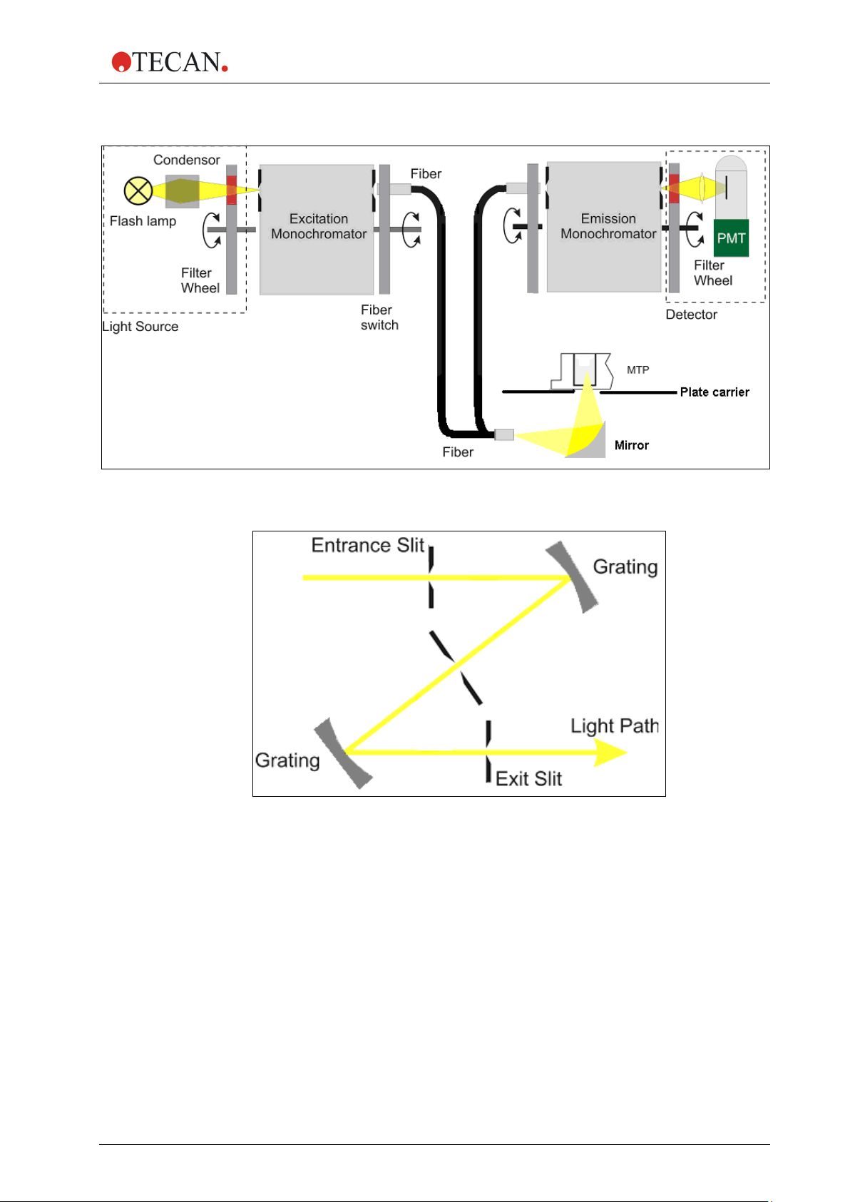
2.5.1 Fluorescence Intensity System (Infinite M200 PRO)
The optical system of the fluorescence top and bottom system of the Infinite
M200 PRO is sketched below.
The system consists of:
1. Light source system
2. Excitation double monochromator
3. Fluorescence top optics
4. Emission double monochromator
5. and fluorescence detection
The solid arrows indicate the light path of the excitation light; the dashed arrows
indicate the emission light path.
To simplify the system, the ‘Flash Monitor’ (see section F lash Mon itor , pag e 27) is
not shown. Each monochromator unit, (2) and (4), is built of two gratings and a
schematic view is displayed in more detail in the figures below.
Fluorescence Intensity Top Diagram
Figure 8: Optical System Fluorescence Top
24 IFU for Infinite 200 PRO No. 30052730 Rev. No. 1.6 2016-04
Page 25
2. General Description
Fluorescence Intensity Bottom Diagram
Figure 9: Optical System Fluorescence Bottom
Figure 10: Detailed view of excitation and emission double monochromator unit
2016-04 IFU for Infinite 200 PRO No. 30052730 Rev. No. 1.6 25
Page 26

2. General Description
Fluorescence Intensity Light Source System
Fluorescence applications usually require a specific range of excitation
wavelengths. Additionally, pulsed excitation light may be required (Time Resolved
Fluorescence [TRF]).
The Infinite M200 PRO light source system is built from the following
components:
• Flash Lamp
• Condensing Optics
• Filter Wheel
• Excitation Double Monochromator
• Fiber Optic Bundle
• Flash lamp Monitor
Flash Lamp
The Infinite M200 PRO utilizes a high energy Xenon arc discharge lamp (flash
lamp). The flash sparks across a small gap between two electrodes. The lamp
bulb contains a high pressure Xenon atmosphere. The flash decays within a few
microseconds. The flash frequency is 40 Hz.
The Infinite M200 PRO uses the flash lamp for fluorescence and for absorbance
measurements, although pulsed illumination is a must only for TRF. The main
benefits of this singular kind of lamp are:
1. High intensity from the deep UV to the near IR
2. Very long lifetime
3. Many applications - only one kind of lamp
4. No warm up time required
Condenser
Condenser type optics from fused silica focus the flash light onto the entrance slit
of the excitation monochromator.
Filter Wheel
A filter wheel is located between the condenser and the excitation
monochromator. The filter wheel contains wavelength specific optical filters,
which are necessary to block undesired diffraction orders produced by the optical
gratings. The filters are set automatically.
Excitation Double Monochromator
In both fluorescence and absorbance applications, the Excitation Double
Monochromator is used to select any desired wavelengths from the flash lamp
spectrum in the range from 230 nm to 600 nm (standard version) or
230 to 850 nm (spectrally enhanced version) for fluorescence intensity and from
230 nm to 1000 nm for absorbance app lica tio ns .
Fluorescence emission spectra in many cases do not depend on the exact
excitation wavelength. For a maximum total fluorescence signal; therefore, rather
broad excitation bandwidth may be used. The bandwidth of the Infinite M200
PRO monochromator system is < 9 nm for wavelengths > 315 nm and < 5 nm for
wavelengths ≤ 315 nm.
For a more detailed description of how a monochromator works, see below.
26 IFU for Infinite 200 PRO No. 30052730 Rev. No. 1.6 2016-04
Page 27

2. General Description
Description of how a Monochromator Works
A monochromator is an optical instrument that enables any wavelength to be
selected from a defined optical spectrum. Its method of operation can be
compared to a tunable optical filter, whic h allo ws bot h the wav ele ngt h and
bandwidth to be adjusted.
A monochromator consists of an entrance slit, a dispersive element and an exit
slit. The dispersive element diffracts the light into the optical spectrum and
projects it onto the exit slit. A dispersive element can be realized by using a glass
prism or an optical grating. Modern monochromators such as those used in the
Infinite M200 PRO are designed with optical gratings.
Rotating the optical grating around its vertical axis moves the spectrum across
the exit slit and only a small part of the spectrum (band pass) passes through the
exit slit. This means that when the monochromator entrance slit is illuminated with
white light, only light with a specific wavelength (monochromatic light) passes
through the exit slit. The wavelength of this light is set by the rotation angle of the
optical grating. The bandwidth is set by the width of the exit slit. The bandwidth is
defined as full width at half maximum (FWHM).
Monochromators block undesired wavelengths, typically amounting to 10
means when the monochromator is set for light with a wavelength of 500 nm and
the detector detects a signal of 10,000 counts, light with different wavelengths
creates a signal of only 10 counts. For applications in the fluorescence range, this
blocking is often not sufficient, since the fluorescence light to be detected is
usually much weaker than the excitation light. To achieve a higher level of
blocking, two monochromators are connected in series, i.e. the exit slit of the first
monochromator acts as the entrance slit of the second monochromator
simultaneously. This is known as a double monochromator. In this case, the
blocking count reaches a factor of 10
filters.
In the Infinite M200 PRO, a double monochromator is installed on both the
excitation and detection side. This opens the opportunity for easy selection of
excitation and fluorescence wavelengths with no limitations by cut off filters.
3
. This
6
, a value typically achieved by Interference
Fiber Optic Bundle
Light from the exit slit of the Excitation Monochromator is coupled into a fiber
optic bundle, which guides the light either to the top measuring optics or the
bottom measuring optics. The lower end of each fiber bundle acts as a color
specific light source. In both cases, a small portion of the light is always guided to
the flash lamp monitor diode.
Flash Monitor
The light energy of single flashes may fluctuate slightly. To take these variations
into account, a silicon photodiode monitors the energy of every single flash.
Fluorescence and Absorbance measurement results are compensated
correspondingly.
2016-04 IFU for Infinite 200 PRO No. 30052730 Rev. No. 1.6 27
Page 28

2. General Description
Fluorescence Top/Bottom Optics
Flash light enters the optical system and is focused by the condenser ont o the
entrance slit of the Excitation Monochromator. The wavelength of the excitation
light is selected within the monochromator. After passing the monochromator, the
excitation light is coupled into a fiber bundle, which guides the light to the top or
bottom measuring head. The light is then focused into the sample by the
top/bottom lens system.
The fluorescence light is collected by the top/bottom lens system again, coupled
into the fluorescence fiber bundles and guided to the detection system.
The Fluorescence Measuring Optics Top is built from the following components:
• Fluorescence Intensity Lens System Top
• Fluorescence Fiber Bundle
• The bottom optics consists of the following components:
• Fluorescence Bottom Mirror
• Fluorescence Fiber Bundle
Fluorescence Intensity Lens System Top
The exit side of the bundle acts as a color specific light source. The lens system
at the end of the excitation top fiber is designed to focus the excitation light into
the sample, and also collect the fluorescence light and focus it back onto the
fluorescence fiber bundle.
The objective lenses are made from fused silica. This material provides high UV
transmission and is virtually void of auto-fluorescence.
Excitation Spot Size
The size of the fiber bundle cross section determines the diameter of the beam
waist (spot size) in the microplate well. The spot diameter for the M-series is
about 3 mm for the top optics and 2 mm (standard) or 4 mm (enhanced) for the
bottom optics.
Fluorescence Fiber Bundle Top and Bottom
The fiber bundle plugged into the top/bottom measuring head contains a
homogeneous mixture of both excitation and emission fibers. The emission fibers
guide the fluorescence light emission monochromator head where a lens system
focus the light onto the entrance slit of the Emission Monochromator.
Fluorescence Bottom Mirror
The exit side of the bundle acts as a color specific light source. The mirror at the
end of the excitation bottom fiber is designed to focus the excitation light into the
sample and also collects the fluorescence light and focuses it back onto the
fluorescence fiber bundle.
Z-Positioning (Fluorescence Top on Infinite M200 PRO only)
The height of the objective above the sample can be adjusted using the Zposition function. As excitation light is reflected by the sample fluid, z-adjustment
helps to maximize the signal-to-noise ratio. For further details about z-positioning
see chapter 5.5.2 Z-Optimization (FI Top measurements with the Infinite M200
PRO only).
28 IFU for Infinite 200 PRO No. 30052730 Rev. No. 1.6 2016-04
Page 29

2. General Description
Fluorescence Intensity Detection
The fluorescence detection system is used for both measuring modes:
fluorescence from above (top) and below the microplate wells (bottom).
The fluorescence light is focused onto the entrance slit of the Emission
Monochromator. After passing the monochromator the light is focused onto the
detector (PMT). A filter wheel is located between the monochromator and the
PMT.
The Fluorescence Detection system is built from the following components:
• Emission Double Monochromator
• Filter Wheel PMT
• PMT Detector
Emission Double Monochromator
Similar to the Excitation Double Monochromator, the Emission Double
Monochromator is used to select any wavelength of the fluorescence signal.
It acts like an adjustable filter to discriminate scatter of excitation light and
nonspecific fluorescence. The wavelength range is selectable from 330 – 600 nm
in the standard instrument and from 280 – 850 nm in the spectrally enhanced
instrument. The bandwidth is 20 nm.
Filter Wheel PMT
The filter wheel contains wavelength specific optical filters, which are necessary
to block undesired diffraction orders produced by the optical gratings. The filters
are set automatically.
PMT Detector
A photo-multiplier tube (PMT) is used for the detection of such low light levels
associated with fluorescence. The Infini te M20 0 PRO is available in two versions:
The PMT of the standard version is sensitive up to 600 nm. The PMT of the
spectrally enhanced version of the Infinite M200 PRO is sensitive up to the near
infrared (NIR) while still having low dark current. Electronic circuitry uses analog
to digital conversion of PMT output current. Adjusting the PMT gain enables
measurement of a wide range of concentrations in lower or higher concentration
domains. For details, see Section 5.5.1 Instrument Parameters.
2016-04 IFU for Infinite 200 PRO No. 30052730 Rev. No. 1.6 29
Page 30
2. General Description
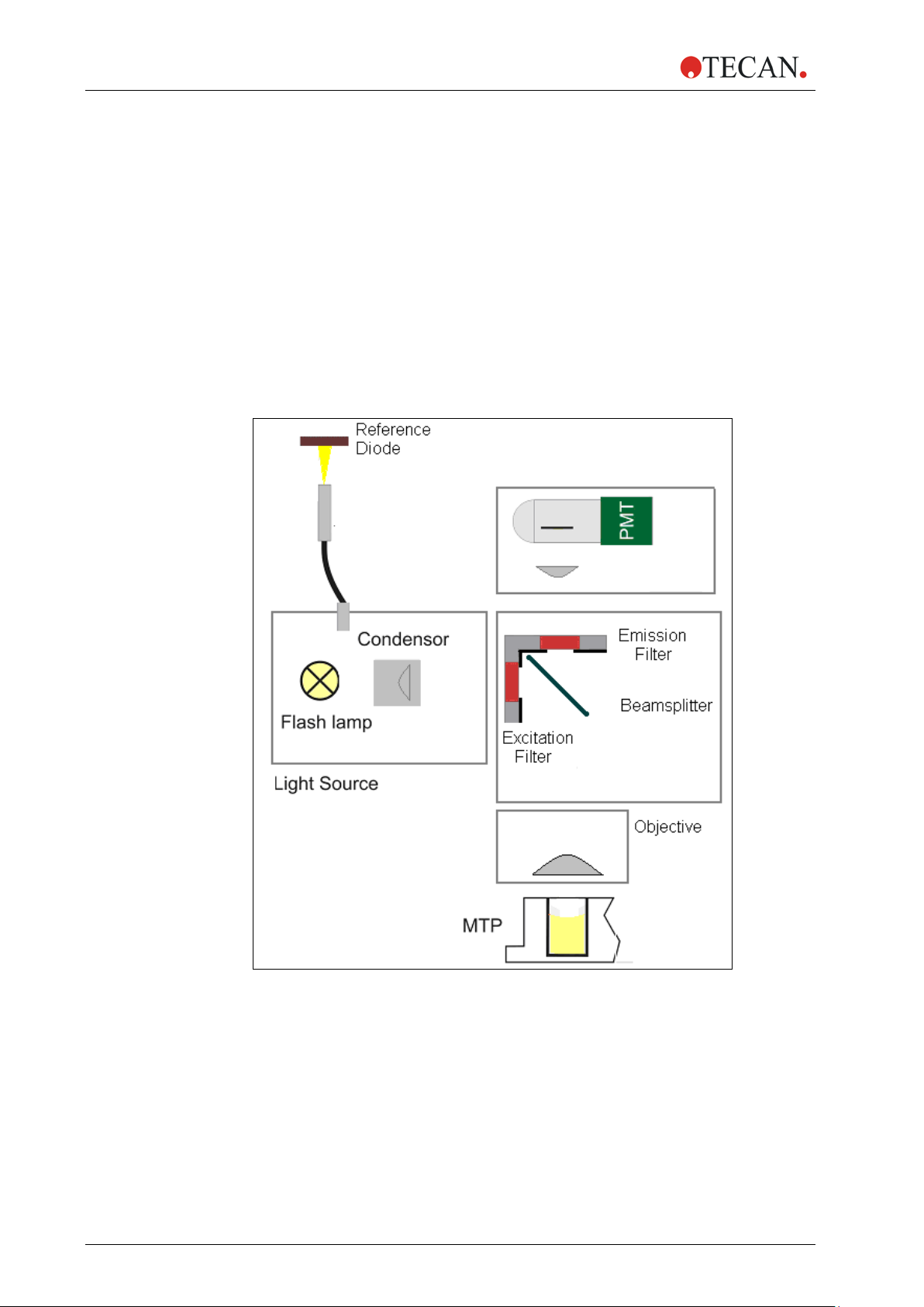
2.5.2 Fluorescence Intensity System (Infinite F200 PRO)
The following parts constitute the fluorescence intensity system of the Infinite
F200 PRO instrument:
1. Light Source
2. Fluorescence Optics
3. Fluorescence Detection System
The fluorescence top system is shown in Figure 11, the bottom system in Figure
12. The solid arrows indicate the excitation light path; the dashed arrows
determine the emission light path.
Fluorescence Intensity Top Diagram
Figure 11: Fluorescence intensity top system of the Infinite F200 PRO
30 IFU for Infinite 200 PRO No. 30052730 Rev. No. 1.6 2016-04
Page 31

2. General Description
Fluorescence Intensity Bottom Diagram
Figure 12: Fluorescence intensity bottom system of the Infinite F200 PRO
2016-04 IFU for Infinite 200 PRO No. 30052730 Rev. No. 1.6 31
Page 32

2. General Description
Light Source System
Flash light enters the optical system by being focused through a slit containing
the filter. This opening acts as a color specific light source.
The Infinite F200 PRO light source system is built from the following components:
• Flash lamp
• Condensing Optics
• Excitation Filters
• Flash lamp Monitor
Flash lamp
The Infinite F200 PRO utilizes a high energy Xenon arc discharge lamp (Flash
lamp). The flash sparks across a small gap between two electrodes. The lamp
bulb contains a high pressure Xenon atmosphere. The flash decays within some
microseconds.
The flash frequency is 40 Hz.
The Infinite F200 PRO uses the Flash lamp for fluorescence and for absorbance
measurements, although pulsed illumination is a must only for TRF. The main
benefits of this singular kind of lamp are:
1. High intensity from the deep UV to the near IR
2. Very long lifetime
3. Many applications - only one kind of lamp
4. No warm up time required
Condenser
Condenser type optics focus the light through the entrance slit to the fluorescence
optical system.
Excitation Filter
Wavelength-specific bandpass filters serve to select the wavelength range of
interest from the whole spectrum of excitation light coming from the flash lamp.
Filters are installed in removable slides and are user-exchangeable.
Flash Monitor
The light energy of single flashes may fluctuate slightly. To take these variations
into account, a reference silicon photodiode monitors the energy of every single
flash. Fluorescence measurement results are compensated correspondingly.
Fluorescence Optics Top
Flash light enters the optical system by being focused through a slit and then
through the excitation filter. Depending on the measured wavelength either a
semi-transparent (50%) or a special dichroic mirror reflects the light towards the
microplate. The objective lens system focuses the light into the sample.
Fluorescence Emission is measured from above the well. Fluorescence light is
collected by the objective, directed through the appropriate mirror, and focused
through the exit slit for detection.
Objective Lens System
The objective is designed to collect the fluorescent light emitted from a well and
focus it through the exit slit to the detection system.
The objective lenses are made from fused silica. This material provides high UV
transmission and is virtually void of auto-fluorescence.
32 IFU for Infinite 200 PRO No. 30052730 Rev. No. 1.6 2016-04
Page 33

2. General Description
Mirror Selection - Fluorescence Top (Infinite F200 PRO only)
The Infinite F200 PRO is equipped with a mirror carrier, which houses a 50%
mirror as well as a 510 dichroic mirror or, alternatively, a specific dichroic for
AlphaScreen/AlphaLISA measurements (see 2.5.8 AlphaScreen/AlphaLISA
System (Infinite F200 PRO only)).
The advantage of the 50% mirror is that is works with any pair of excitation and
emission wavelengths. However, 50% of excitation light that is directed into the
sample and, subsequently, 50% of the emission light coming out of the sample
are lost.
Dichroic mirrors are wavelength dependent and are designed to reflect a certain
range of wavelengths almost entirely. Dichroic mirrors exhibit a high reflection of
excitation light and a high transmission of emission light and usually give a better
signal-to-noise ratio compared to 50% mirrors.
Available for plate formats up to 384 wells.
Note:
A dichroic mirror needs to match the selected fluorescence excitation
and emission wavelengths.
Mirror Type Reflection (Excitation) Transmission (Emission)
50% mirror
510 dichroic (e.g. fluorescein)
650 dichroic (AlphaScreen/Al p haLI SA)
The dichroic mirror used for AlphaScreen/AlphaLISA cannot be used
for standard fluorescence measurements. It is selected automatically
According to the wavelengths defined in the measurement script, the dichroic
mirror is selected automatically if both excitation and emission wavelength match
the specified range of that mirror. If either the excitation or the emission
wavelength does not match the ranges of the dichroic mirror, the 50% mirror is
chosen automatically for the measurement.
230 – 900 nm 230 – 900 nm
320 – 500 nm 520 – 780 nm
665 – 700 nm 540 – 635 nm
Note:
for Alpha measurements.
Fluorescence Optics Bottom
Flash light enters the optical system by being focused through a slit and then
through the excitation filter. The excitation bottom fiber guides the light to the
bottom optics probe, which consists of an elliptical mirror which focuses the light
through the bottom of the microplate into the well. The emitted light is focused
onto the excitation bottom fiber, which guides the light over a mirror through the
emission filter to the fluorescence detection system.
2016-04 IFU for Infinite 200 PRO No. 30052730 Rev. No. 1.6 33
Page 34

2. General Description
Fluorescence Detection
Emission Filter
Wavelength-specific bandpass filters serve to discriminate unspecific
fluorescence signals from the sample-specific emission light of interest. Filters
are installed in removable slides and are user-exchangeable.
Fluorescence filters may be used interchangeably as excitation or emission
filters, depending on the measurement requirements.
The spot diameter for the Infinite F200 is about 2 mm (Standard Bottom Reading)
or 4 mm (Enhanced Bottom Reading), respectively.
PMT Detector
A photomultiplier tube (PMT) is used for the detection of such low light levels as
involved with fluorescence. For details, see section Fluorescence Intensity
Detection, page 29.
2.5.3 Fluorescence Polarization System (Infinite F200 PRO)
For technical details please refer to chapter 2.5.2 Fluorescence Intensity System
(Infinite F200 PRO).
An Infinite F200 PRO configured for Fluorescence Polarization (FP)
measurements is delivered with a standard FP filter slide. The filter slide is
equipped with filters and polarizers for excitation and emission, at 485 and
535 nm respectively, and can be applied for measuring, for example, fluoresceinbased FP applications.
For details on how to mount polarizers and FP filters please refer to
chapter 5.4 Defining Filter Slides (Infinite F200 PRO only).
34 IFU for Infinite 200 PRO No. 30052730 Rev. No. 1.6 2016-04
Page 35

2. General Description
2.5.4 Absorbance Syste m (Infinite F200 PRO)
For absorbance measurements a similar optical path is used as for fluorescence
excitation. The absorbance measurement module is located underneath the plate
carrier. It measures the light being transmitted through the sample. Before
measurement of the microplate, a reference measurement is performed with the
plate carrier moved out of the light beam (see also 2.4.2 Absorbance).
The absorbance system is shown in Figure 13 and consists of the following
components:
• Light Source
• Absorbance Optics
• Absorbance Detection Unit
Figure 13: Absorbance System of the Infinite F200 PRO
2016-04 IFU for Infinite 200 PRO No. 30052730 Rev. No. 1.6 35
Page 36

2. General Description
Light Source System
The absorbance light source system is similar to the fluorescence top system.
Band Pass Filter
In absorbance applications, optical filters of band pass type are necessary to
select the useful wavelengths from the flash lamp spectrum. Filters are mounted
in removable slides.
Absorbance Filter
Absorbance measurements require relatively narrow band pass filters (2 – 10 nm)
with steep slopes.
Absorbance Optics
The mirror carriage has an absorbance position. A pair of small slits forms a
narrow and more collimated light beam when compared with fluorescence
excitation.
Light focused through the dispensed liquid is slightly refracted at the interfaces
between air, liquid, and plate bottom. To accomplish a reliable measurement in
the presence of the meniscus, a focusing lens recollects the rays of light, which
might have been refracted too far away from the optical axis.
The spot size of the absorbance light beam is 0.5 mm (diameter).
Absorbance Detection
A silicon photodiode is used for the measurement of the light beam. It is sensitive
to a wide range of wavelengths. The photodiode is well suited for the light levels
being encountered with absorbance measurements up to 4 OD.
Note
For absorbance measurement of nucleic acids
in small volumes (2 µl) use Tecan’s NanoQuant PlateTM.
With this device it is possible to measure
16 different samples in one measurement.
For further information please contact
your local Tecan distributor or visit: www.tecan.com.
36 IFU for Infinite 200 PRO No. 30052730 Rev. No. 1.6 2016-04
Page 37

2. General Description
2.5.5 Absorbance System (Infinite M200 PRO)
For absorbance measurements, a similar optical path is used as for fluorescence
excitation.
The absorbance system consists of:
1. light source
2. excitation monochromator
3. absorbance MTP optics
4. absorbance MTP measurement module
Condenser type optics focus the light through the excitation filter and then
through the entrance slit to the excitation monochromator. A fiber bundle then
guides the light from the excitation monochromator to the absorbance MTP
optics, which focuses the light into the wells. The absorbance MTP measurement
module is located underneath the plate carrier. These modules measure the light
being transmitted through the sample.
Before measurement of the microplate (MTP), a reference measurement is
performed with the plate carrier moved out of the light beam.
Figure 14: Optical System Absorbance Infinite M200 PRO
For details about the light source (1) and the excitation monochromator (2),
please refer to Fluorescence Intensity Light Source System, page 26.
2016-04 IFU for Infinite 200 PRO No. 30052730 Rev. No. 1.6 37
Page 38

2. General Description
Absorbance Optics MT P
A fiber bundle guides the light from the excitation monochromator system to the
absorbance MTP optics.
The absorbance optics consists of a pair of lenses focusing the light beam into
the well of the microplate.
The spot size of the absorbance light beam is 0.7 mm in diameter.
Absorbance Detection MTP
A silicon photodiode is used for the measurement of the transmitted light. It is
sensitive to a wide range of wavelengths. The photodiode is well suited for the
light levels being encountered w ith absor ba nc e m easur ements up to 4 OD.
Note
For absorbance measurement of nucleic acids
in small volumes (2 µl) use Tecan’s NanoQuant PlateTM.
With this device it is possible to measure
16 different samples within one measur ement.
For further information please contact
your local Tecan distributor or visit:
www.tecan.com
38 IFU for Infinite 200 PRO No. 30052730 Rev. No. 1.6 2016-04
Page 39

2. General Description
2.5.6 Luminescence System
The Infinite 200 PRO Luminescence System consists of the following parts:
• Luminescence Optics
• Detection Unit (Basic or Standard PMT)
Figure 15: Optical System Luminescence
The luminescence fiber bundle guides the light from the sample to the detection
unit (PMT) passing through a filter wheel. The photon counting PMT
(photomultiplier tube) is designed for applications in chemo- and bioluminescence
providing a high dynamic range. The exceptionally low noise and high sensitivity
allows the detection of very low light levels.
The z-position of the luminescence fiber bundle fixed onto the optics carrier is
adjusted automatically by the software and depends on the selected plate
definition file. As light is refracted at the sample liquid surface, z-adjustment helps
to maximize signal to noise and minimize cross-talk.
2016-04 IFU for Infinite 200 PRO No. 30052730 Rev. No. 1.6 39
Page 40

2. General Description
0
10
20
30
40
50
60
70
80
90
100
400 450 500 550 600 650
Wa ve l ength [nm]
Transm issi o n [%]
Luminescence Optics
In luminescence measurement mode, the Inf in ite 20 0 PRO uses fixed microplate
position and a moveable luminescence measurement head (see Figure 15:
Optical System Luminescence). The plate thickness is defined by selecting the
corresponding plate type in the software (see i-control Instructions for Use).
Fiber
A glass fiber guides the light from the sample to the detection unit. The fiber is
designed to measure from 6-well up to 384-well plates.
Filter Wheel
A filter wheel with 6 filter positions in front of the PMT window is switched to the
required luminescence channel. The sensitivity of the detection system makes it
necessary to attenuate high luminescence light levels; therefore, the filter wheel
can also switch a neutral density filter across the selected fiber exit.
Filter Wheel Position Filter
Position 1 Lumi Green*
Position 2 Lumi Magenta*
Position 3 OD2 neutral density filter
Position 4 No attenuation
Position 5 Blue 1**
Position 6 Green 1**
* recommended for the BRET
** recommended for the BRET assay
The OD2 neutral density filter serves to attenuate high light levels by a factor of
100 (corresponding to 2 OD absorbance). The resulting values are automatically
scaled to counts per second and displayed accordingly in the software results
output.
See Figure 16 to Figure 19 for transmission spectra of luminescence filters.
2
assay and the ChromaGlo - Luciferase Assay
40 IFU for Infinite 200 PRO No. 30052730 Rev. No. 1.6 2016-04
Figure 16: Transmission spectrum of filter ‘Lumi Magenta’
Page 41

2. General Description
0
10
20
30
40
50
60
70
80
90
100
400 450 500 550 600 650 700 750
Wavelength [nm ]
Transmissi on [% ]
0
10
20
30
40
50
60
70
80
90
100
400 450 500 550 600 650 700 750
Wavelength [nm ]
Transmissi on [% ]
Figure 17: Transmission spectrum of filter ‘Lumi Green’
Figure 18: Transmission spectrum of filter ‘Blue 1’
2016-04 IFU for Infinite 200 PRO No. 30052730 Rev. No. 1.6 41
Figure 19: Transmission spectrum of filter ‘Green 1’
Page 42

2. General Description
2.5.7 Cuvette Port (Infinite M200 PRO)
The Infinite M200 PRO may be optionally equipped with a cuvette port for
absorbance measurements.
For absorbance measurements with the cuvette port of Infinite M200 PRO a
similar optical path is used as for fluorescence excitation.
The absorbance system consists of:
1. light source
2. excitation monochromator
3. absorbance cuvette measurement module
4. absorbance microplate module
Condenser type optics focus the light through the excitation filter and then
through the entrance slit to the excitation monochromator. A fiber bundle then
guides the light from the excitation monochromator to the absorbance cuvette
optics, which focuses the light through the cuvette. The absorbance cuvette
measurement module is located right after the cuvette port. A silicon photo diode
measures the light being transmitted through the sample. Before measurement of
the cuvette, a reference measurement against air is performed with the cuvette
port moved out of the light beam.
Figure 20: Optical System of the absorbance module of Infinite M200 PRO including the
cuvette port The figure also shows the light path of the absorbance microplate module (5).
For details of the light source (1) and the excitation monochromator (2), please
42 IFU for Infinite 200 PRO No. 30052730 Rev. No. 1.6 2016-04
refer to chapter 2.4.1 Fluorescence/A) Fluorescence Intensity (FI).
Page 43

2. General Description
The cuvette port is an option of the Infinite M200 PRO only. This option
is not available for the Infinite F200 PRO. With the Infinite F200 PRO,
cuvettes may be measured using a Tecan Cuvette Adapter placed on
Absorbance Optics Cuvette
A fiber bundle guides the light from the excitation monochromator system to the
absorbance cuvette optics.
This optics consists of a pair of lenses focusing the light beam into the cuvette.
At the focal point, the spot diameter of the absorbance light beam is 1.9 mm.
Absorbance Detection Cuvette
A silicon photodiode is used for the measurement of the transmitted light. It is
sensitive to a wide range of wavelengths. The photodiode is well suited for the
light levels being encountered w ith absor ba nc e m easur ements below 4 OD.
Measurement values above 4 OD are marked as ‘OVER’ in the result sheet.
Note
the plate transport.
Cuvette types
The cuvette port is compatible with the following cuvettes:
Cuvette Type Width x Depth
Standard
cuvettes
Semi-macro
cuvettes
Micro
cuvettes
Ultra-micro
cuvettes
12.5 x 12.5 mm 55 mm 2 ml
12.5 x 12.5 mm 55 mm 1 ml
12.5 x 12.5 mm 55 mm 0.5 ml
12.5 x 12.5 mm 55 mm 100 µl
Cuvettes with a measurement wind o w < 2 mm (diam eter) cannot be used.
Maximum
Height
(including lid)
Filling
Volume
Example
Hellma 110 QS,
10 mm
Hellma 108-QS,
10 mm
Hellma 104.002 QS,
10 mm
Hellma 105.202,
10 mm
∗
∗
∗
∗
∗
Hellma GmbH & Co. KG, Germany; www.hellma-worldwide.com
2016-04 IFU for Infinite 200 PRO No. 30052730 Rev. No. 1.6 43
Page 44

2. General Description
Caution
STOP
STOP
Inserting the Cuvette
The cuvette holder is attached securely to the cuvette carrier and moves the
cuvette in and out. The cuvette carrier is an integral part of the instrument and
cannot be removed.
Always use a valid filling volume. Make sure that the liquid level in the
cuvette exceeds 20 mm (height). Otherwise the light path in the cuvette
might not be filled completely with liquid which can lead to wrong
measurement results.
CAUTION
THE CUVETTE PORT OF THE INFINITE M200 PRO CANNOT BE USED
FOR CUVETTES WITH A MEASUREMENT WINDOW < 2 MM
(DIAMETER) AND A CENTER HEIGHT BELOW 15 MM.
Figure 21: Cuvette Port Infinite M200 PRO
The cuvette has to be inserted so that the measurement window of the cuvette
corresponds to the measurement window of the cuvette holder:
Figure 22: How to insert the cuvette into the cuvette holder
44 IFU for Infinite 200 PRO No. 30052730 Rev. No. 1.6 2016-04
Page 45

2. General Description
2.5.8 AlphaScreen/AlphaLISA System (Infi nite F200 PRO only)
For uncompromised performance, the Infinite F200 PRO uses its dedicated
fluorescence top detection module (see chapter 2.5.2) for
AlphaScreen/AlphaLISA measurements. The AlphaScreen/AlphaLISA module
utilizes the instrument’s flash lamp as a light source in combination with a
680(30) nm excitation filter and dedicated emission filters for AlphaScreen and
AlphaLISA, respectively. A dichroic mirror optimized for the AlphaScreen and
AlphaLISA wavelengths serves to maximize the excitation and emission light
intensities and is selected automatically for Alpha measurements.
Note
AlphaScreen/AlphaLISA measurements are only possible as endpoint
measurements in white or light gray microp lates and cannot be
performed in combination with the injector system and the heating
system.
AlphaScreen/AlphaLISA Mirror
The Infinite F200 PRO with AlphaScreen/AlphaLISA option is equipped with a
dichroic mirror optimized for Alpha assays. The mirror is selected automatically
for all Alpha measurements.
Mirror type Reflection (Excitation) Transmission (Emission)
650 dichroic (AlphaScreen/Al p haLI SA)
665 – 700 nm 540 – 635 nm
2016-04 IFU for Infinite 200 PRO No. 30052730 Rev. No. 1.6 45
Page 46

2. General Description
0
10
20
30
40
50
60
70
80
90
100
500 530 560 590 620 650 680
Wave l ength [nm]
Transm ission [%]
0
10
20
30
40
50
60
70
80
90
100
500 530 560 590 620 650 680
Wa ve l ength [nm]
Transm issio n [% ]
Emission Filters
The Infinite F200 PRO is equipped with two dedicated emission filters for
AlphaScreen and AlphaLISA measurements, respectively. Depending on the
experimental setup, the user may select either the AlphaScreen or AlphaLISA
emission filter to optimize the signal in the desired wavelength range. The
transmission characteristics of both filters are summarized in figure 23 and figure
24.
Figure 23: Transmission spectrum of filter ‘AlphaScreen’.
Figure 24: Transmission spectrum of filter ‘AlphaLISA’.
PMT Detector
AlphaScreen/AlphaLISA signals are recorded using an ultrasensitive
photomultiplier tube (PMT). Adjusting the PMT gain enables measurement of a
wide range of concentrations with lower or higher signals.
For AlphaScreen and AlphaLISA measurements it recommended to calculate the
46 IFU for Infinite 200 PRO No. 30052730 Rev. No. 1.6 2016-04
gain from a well containing the highest signal/concentration using the ‘calculated
from well’ function. For fastest-possible measurement speed, the gain may be
determined in a pre-measurement of the well with the highest signal and then set
manually. For details see Section 5.5.1 Instrument Parameters.
Note
The installed Alpha excitation and emission filters are optimized for
AlphaScreen/AlphaLISA measurements and should not be used for
fluorescence measurements.
Note
The dichroic mirror used for AlphaScreen/AlphaLISA cannot be used for
standard fluorescence measurements. It is selected automatically for
Alpha measurements.
Page 47

3. Installation
3. Installation
3.1 Unpacking and Inspection
The delivered packaging includes the following items:
• CABLE USB 2.0 A/B 1.8 M Black with housing recepta c le ferr ite
• CDROM Infinite F200 PRO/Infinite M200 PRO
• OOB Quality Report
• Transport lock (mounted)
• Instructions for Use
• Final test protocol
The Infinite F200 PRO packaging includes additionally the following items:
• Accessory Box
• Filter stop rings (8)
• Filter assembly tool
• Plastic tweezers
• Filter slide
The injector module packaging for 1 injector includes the following items:
• Bottle holder
• Beaker for priming
• 125 ml bottle brown
• Injector dummy (mounted)
• Waste tub
• 15 ml bottle
The second injector comes with the following items:
• Bottle holder
• Beaker for priming
• Waste tub
• 15 ml bottle
CAUTION
STOP
2016-04 IFU for Infinite 200 PRO No. 30052730 Rev. No. 1.6 47
THE READER HAS BEEN TESTED WITH THE SUPPLIED USB CABLE.
IF ANOTHER USB CABLE IS USED, TECAN AUSTRI A CANNOT
GUARANTEE THE CORRECT PERFORMANCE OF THE INSTRUMENT.
Page 48

3. Installation
3.1.1 Unpacking Procedur e
1. Visually inspect the container for damage before it is opened.
Report any damage immediately .
2. Select a location to place the instrument that is flat, level, vibration free,
away from direct sunlight, and free from dust, solvents and acid vapors.
Allow at least 10 cm distance between the back of the instrument and the
wall or any other equipment. Ensure that the plate carrier cannot be
accidentally hit when moved out. Ensure that the main switch and the
main cable can be reached at all times and are in no way obstructed.
3. Place the carton in an upright position and open it.
4. Lift the instrument out of the carton and place it in the selected location.
Take care when lifting the instrument and ensure that it is held on both
sides.
5. Visually inspect the instrument for loose, bent or broken parts.
Report any damage immediately.
6. Compare the serial number on the rear panel of the instrument with the
serial number on the packing slip.
Report any discrepancy immediately.
7. Check the instrument accessories against the packing list.
8. Save packing materials and transport locks (see next section) for further
transportation purposes.
STOP
STOP
STOP
WARNING
THE INFINITE 200 PRO IS A PRECISION INSTRUMENT AND
WEIGHS FULLY EQUIPPED APPROX. 16 KG.
CAUTION
THE MAXIMUM LOAD FOR THE INFINITE 200 PRO COVER IS 16 KG;
HOWEVER THE LOAD MUST BE DISTRIBUTED EVENLY ACROSS THE
ENTIRE SURFACE OF THE COVER.
CAUTION
THE MAXIMUM LOAD FOR THE INFINITE 200 PRO PLATE
TRANSPORT IS 100 G. OVERLOADING THE PLATE CARRIER CAN
CAUSE INSTRUMENT DAMAGE WHICH MAY REQUIRE SERVICE.
CAUTION
ALLOW AT LEAST 10 CM DISTANCE BETWEEN THE BACK OF THE
INSTRUMENT AND THE WALL OR ANY OTHER EQUIPMENT.
CAUTION
STOP
48 IFU for Infinite 200 PRO No. 30052730 Rev. No. 1.6 2016-04
THE INSTRUMENT MUST BE PLACED IN A LOCATION AWAY FROM
DIRECT SUNLIGHT. ILLUMINATION > 500 LUX CAN NEGATIVELY
INFLUENCE LUMINESCENCE MEASUREMENTS.
Page 49

3. Installation
3.2 Removal of the Transport Locks
CAUTION
STOP
The instrument is delivered with the plate carrier locked into place, so that it
cannot be damaged. Before the instrument can be used the transport lock must
be removed using the following procedure:
1. Ensure that the instrument is disconnected from the main power supply.
2. Open the plate carrier compartment flap.
3. Remove the screws and pull the plate carrier out manually.
REMOVE THE TRANSPORT LOCK
BEFORE OPERATING THE INSTRUMENT.
4. Remove the screws from the transport lock.
5. Remove the transport lock from the plate carrier.
6. The transport locks should be saved for further transportation purposes.
2016-04 IFU for Infinite 200 PRO No. 30052730 Rev. No. 1.6 49
Page 50

3. Installation
CAUTION
STOP
SAVE PACKING MATERIALS AND TRANSPORT LOCKS FOR FURTHER
TRANSPORTATION PURPOSES. THE INFINITE 200 PRO MUST BE
SHIPPED ONLY WITH THE ORIGINAL PACKAGING AND INSTALLED
TRANSPORT LOCKS.
3.3 Transport and Storage
3.3.1 Transport
The Infinite 200 PRO must be shipped using the original packing and installed
transport locks. Before shipping the instrument, it must be thoroughly disinfected
(see 8.4 Instrument Disinfection).
3.3.2 Storage
Before storing the instrument the injectors must be rinsed using a wash
procedure (see 5.10.2 Priming and Washing of the Infinite 200 PRO). Select a
location to store the instrument that is flat, level, vibration free, away from direct
sunlight, and free from dust, solvents and acid vapors
Storage Specifications
Temperature - 20 °C to + 60 °C -4 °F to + 140 °F
Relative Humidity < 80 % non condensing
50 IFU for Infinite 200 PRO No. 30052730 Rev. No. 1.6 2016-04
Page 51

3. Installation
3.4 Power Requirements
The instrument is auto sensing and it is therefore not necessary to make any
changes to the voltage range. Check the voltage specifications on the rear panel
of the instrument and ensure that the voltage supplied to the instrument is correct
to this specification.
The voltage range is 100-120/220-240V.
If the voltage is not correct, please contact your distributor.
CAUTION
STOP
DO NOT USE THE INSTRUMENT IF THE VOLTAGE SETTING IS NOT
CORRECT. IF THE INSTRUMENT IS SWITCHED ON WITH THE
INCORRECT VOLTAGE SETTING IT WILL BE DAMAGED.
WARNING
IF THE INSTRUCTIONS GIVEN IN THIS DOCUMENT ARE NOT
CORRECTLY PERFOR MED, THE INSTRUMENT WILL EITHER BE
DAMAGED O R THE PROCED U RE WILL NO T BE PER FORMED
CORRECTLY A ND THE SAFETY OF THE INSTRUMENT IS NOT
GUARANTEED.
2016-04 IFU for Infinite 200 PRO No. 30052730 Rev. No. 1.6 51
Page 52

3. Installation
3.5 Switching the Instrument On
CAUTION
STOP
STOP
BEFORE THE INSTRUMENT IS SWITCHED ON FOR THE FIRST TIME
AFTER INSTALLATION,
IT SHOULD BE LEFT TO STAND FOR AT LEAST 3 HOURS, SO THERE
IS NO POSSIBILITY OF CONDENSATION CAUSING A SHORT CIRCUIT.
1. Ensure the computer is switched OFF and the instrument's main power
switch on the back panel of the instrument is in the OFF position.
2. Connect the computer to the instrument with the delivered USB interface
cable.
3. Insert the power cable into the main power socket (with protective ground
connection) on the back panel of the instrument.
4. All connected devices must be approved and listed as per IEC 60950-1
Information Technology Equipment – Saf et y or equiva l ent local
standards.
5. Switch the instrument ON using the main power switch on the back panel
of the instrument.
CAUTION
THE READER HAS BEEN TESTED WITH THE SUPPLIED USB CABLE.
IF ANOTHER USB CABLE IS USED, TECAN AUSTRI A CANNOT
GUARANTEE THE CORRECT PERFORMANCE OF THE INSTRUMENT.
52 IFU for Infinite 200 PRO No. 30052730 Rev. No. 1.6 2016-04
Page 53

4. Gas Control Module (Enhanced)
4. Gas Control Module (Enhanced)
4.1 Safety
1. Always follow basic safety precautions when using the gas control module to
reduce the risk of injury, fire, or electrical shock.
2. Read and understand all information in this chapter. Failure to read,
understand, and follow the instructions in this chapter may result in damage
to the instrument or gas control module, injury to operating personnel or poor
instrument performance.
3. The instrument covers of the gas control module protect the user; therefore,
do not remove any of the covers or perform any maintenance tasks other
than those described in this document.
4. Observe all WARNING, CAUTION and IMPORTANT statements in this
chapter. Ensure that this safety information is accessible for every employee
working with the gas control module.
5. Furthermore, it is assumed that instrument operators, due to their vocational
experience, are familiar with the necessary safety precautions for handling
gas and biohazardous substances. Adhere to the following guidelines:
WARNING
The gas control module (GCM) is designed
for CO2 (carbon dioxide) and N2 (nitrogen) supply
and must only be used by trained personnel.
Never use a flammable or cryogenic gas supply!
WARNING
ADEQUATE VENTILATION MUST BE PROVIDED
FOR THE ROOM IN WHICH CO2 AND N2 ARE USED.
WARNING
FOLLOW THE SECURITY MEASURES
FOR WORKING WITH COMPRESSED GAS! (TRANSPORTATION,
STORAGE, HANDLING AND USE).
THE CO2 AND N2 GAS CYLINDERS MUST BE SECURELY FASTENED
UPRIGHT TO A LARGE, STATIONARY OBJECT AT ALL TIMES.
ALWAYS PROTECT THE GAS CYLINDER FROM FALLING!
A COMPRESSED GAS CYLINDER WHICH FALLS AND IS DAMAGED
CAN EASILY BECOME A LETHAL PROJECTILE!
• Wear protective glasses when using compressed gasses outside of the
instrument when the instrument is open.
• Precautions must be taken when working with potentially infectious
material. Make sure to treat biohazardous material according to
applicable safety standards and regulat ions as well as good laborat ory
practice guidelines.
2016-04 IFU for Infinite 200 PRO No. 30052730 Rev. No. 1.6 53
Page 54

4. Gas Control Module (Enhanced)
4.2 Gas Control Module Features
The gas control module enhanced (GCMTM) offers a comprehensive solution for a
variety of cell-based applications for the Infinite 200 PRO multimode reader.
Two integrated gas inlets allow the external control of CO
maintain stable culture conditions and improve cell growth. Carbon dioxide
concentration is regulated by an inflow of CO
achieved by supplying N
gas.
2
2
The GCM makes the Infinite 200 PRO ideally suited for in vitro studies of
eukaryotic cell lines or extends the usage of the instrument for microplate
investigations using anaerobe or facultative anaerobic bacteria.
4.2.1 Gas Control Module Configurations
Settings:
The O
The O
The CO
The CO
The Accuracy of measured O
The Accuracy of measured CO
The GCM is available in two configurations:
• ‘CO2 and O2’ configuration: CO
• ‘CO2’ configuration: CO
concentration can be set in the range from 0.1 – 21 vol. %.
2
control range is 0.1 – 21 vol. %.
2
concentration can be set in the range from 0 – 10 vol. %.
2
control range is 0 – 10vol. %.
2
concentration is +/- 0.9 vol. %.
2
concentration is +/- 1 vol. %.
2
and/or O2 concentrations can be
2
regulated inside the reader chamber.
concentration can be regulated inside the reader
2
chamber
gas, whereas oxygen reduction is
and O2 to help
2
‘CO2’ and ‘O2’ Configuration
There are four gas control modes available for the GCM enhanced with
‘CO2 and O2’ configuration:
• Carbon Dioxide Mode: In CO2 Mode, CO
instrument (plate carrier compartment/reader chamber).
• Oxygen Mode: In O2 Mode, N2 gas is introduced to reduce the oxygen gas
concentration inside the instrument to below ambient air levels.
• DUAL Mode: In DUAL Mode, the flow of CO
automatically by opening or closing the valve while monitoring both
concentrations (vol. %) inside the instrument.
• Manual Mode: In Manual Mode, the flow of CO
by opening or closing the valve manually while monitoring both
concentrations (vol. %) inside the instrument.
gas is introduced into the
2
and N2 gas is controlled
2
and/or N2 gas is controlled
2
54 IFU for Infinite 200 PRO No. 30052730 Rev. No. 1.6 2016-04
Page 55

4. Gas Control Module (Enhanced)
‘CO2’ Configuration
There are two gas control modes available for the GCM enhanced with
‘CO2’ configuration:
• Carbon Dioxide Mode (CO2 Mode)
• Manual Mode
o For instruments with ‘CO2’ configuration,
‘O2 NO SENSOR’ will appear on the display.
For the GCM with ‘CO2’ configuration,
O2 Mode and Dual Mode menus are unavailable and not displayed.
4.2.2 Top and Rear Views of the Gas Control Module
The pictures below show the outer features of the gas control module.
Front View
Rear View
2016-04 IFU for Infinite 200 PRO No. 30052730 Rev. No. 1.6 55
Page 56

4. Gas Control Module (Enhanced)
Control Panel
The control panel, which consists of a display panel and a key pad, is located on
the top of the GCM enhanced.
1. Displa y panel
2. Power/gas flow indicator (LED)
3. Mode key
4. Plus key
5. Minus key
6. I/O key (On/Off) (Start/Stop)
56 IFU for Infinite 200 PRO No. 30052730 Rev. No. 1.6 2016-04
Page 57

4. Gas Control Module (Enhanced)
4.3 Main Menu of Modes
The main menu consists of the available gas control modes. All four gas control
modes are present in the ‘CO2 and O2’ configuration, whi le in the ‘CO2 ’
configuration only the CO2 Mode and Manu al Mod e ar e availa ble .
Press ‘Mode’ to switch between modes in the main menu (gas regulation must be
stopped - and valves must be close d in Manual Mo de - before it is possible to
switch modes).
4.3.1 CO2 Mode
In CO2 Mode, it is possible to regulate CO2 gas concentration by setting the
target value and starting the gas control module (CO
instrument).
gas is introduced into the
2
1. Select the mode by pressing the ‘I/O’ key, the following display appears:
2. Change target value for ‘CO2’ (using the plus and minus keys)
The editable target value blinks (highlighted in gray above)
3. Press the ‘I/O’ key to Start/Stop gas regulation. The ‘actual’ value shows
the current gas concentration inside the reader. (LED blinks when gas
regulation is running - LED is stable gas regulation is stopped).
4. Press the ‘Mode’ key for 1.5 seconds to return to the ‘CO2 Mode’ display
(main menu).
2016-04 IFU for Infinite 200 PRO No. 30052730 Rev. No. 1.6 57
Page 58

4. Gas Control Module (Enhanced)
4.3.2 O2 Mode
In O2 Mode, it is possible to regulate O2 gas concentration by setting the target
value and starting the gas control module. (Nitrogen gas is introduced to reduce
the oxygen gas concentration inside the instrument to below ambient air levels).
1. Select the mode by pressing the ‘I/O’ key, the following display appears:
2. Change target value for ‘O2’ (using the plus and minus keys)
The editable target value blinks (highlighted in gray above)
3. Press the ‘I/O’ key to Start/Stop gas regulation. The ‘actual’ value shows
the current gas concentration inside the reader. (LED blinks when gas
regulation is running - LED is stable gas regulation is stopped).
4. Press the ‘Mode’ key for 1.5 seconds to return to the ‘O2 Mode’ displa y
(main menu).
58 IFU for Infinite 200 PRO No. 30052730 Rev. No. 1.6 2016-04
Page 59

4. Gas Control Module (Enhanced)
4.3.3 DUAL Mode
In Dual Mode, it is possible to regulate CO2 and O2 gas concentration by setting
target values and starting the gas control module (flow of CO
controlled automatically by opening or closing the valve while monitoring both
concentrations (vol. %) inside the instrument).
and N2 gas is
2
1. Select the mode by pressing the ‘I/O’ key, the following display appears:
2. Change target value for ‘CO2’ (using the plus and minus keys)
The editable target value blinks (highlighted in gray above)
3. Press the ‘Mode’ key to switch to ‘O2’ target settings
4. Change target value for ‘O2’ (using the plus and minus keys)
The editable target value blinks (highlighted in gray above)
5. Press the ‘I/O’ key to Start/Stop gas regulation
Alternating ‘target’ and ‘actual’ (current) values will be displayed. The
‘actual’ value shows the current gas concentration inside the reader. (LED
blinks when gas regulation is running - LED is stable gas regulation is
stopped).
6. Press the ‘Mode’ key for 1.5 seconds to return to the ‘Dual Mode’ display
(main menu).
2016-04 IFU for Infinite 200 PRO No. 30052730 Rev. No. 1.6 59
Page 60

4. Gas Control Module (Enhanced)
4.3.4 Manual Mode
In Manual Mode, it is possible to manually regulate CO2 or O2 gas concentration
(the flow of CO
while monitoring both concentrations (vol. %) inside the instrument).
or N2 gas is controlled by opening or closing th e valve m anuall y
2
1. Select the mode by pressing the ‘I/O’ key,
the following display appears:
2. Press the ‘Mode’ key to switch between ‘CO2’ and ‘O2’.
The selected gas will blink (highlighted in gray above).
For instruments with ‘CO2’ configuration,
‘O2 NO SENSOR’ will app e ar :
3. Press the ‘I/O’ key to switch ON/OFF the gas control for the selected gas
(‘CO2’ for CO
gas supply, ‘O2’ for N2 gas supply)
2
After one gas has been selected, press ‘Mode’ again to select the other
gas and ‘I/O’ to switch ON/OFF the gas control for that gas.
(LED blinks when gas valve is open - LED is stable when gas valve is
closed).
4. Press the ‘Mode’ key for 1.5 seconds to return to the ‘Manual Mode’
display (main menu).
60 IFU for Infinite 200 PRO No. 30052730 Rev. No. 1.6 2016-04
Page 61

4. Gas Control Module (Enhanced)
4.4 Settings Menu
When the gas control module is switched on for the first time, it is important to
adjust the settings.
1. Switch the GCM on.
The LCD display will illuminate immediately, showing the module’s current
firmware version and shortly afterwards the main menu of gas control modes
will appear, accompanied by a short acoustic signal.
2. Press the ‘Mode’ and ‘Plus’ keys simultaneously to go to
‘Settings’.
3. Make the necessary adjustments to the settings in ‘Device name’ and
‘Altitude’.
• Device name: select a letter: A, B, C, D for device name (using the
plus and minus keys), when more than one Infinite 200 PRO with
GCM is connected to a PC (maximum 4 instruments with GCM).
• Altitude: the altitude value can be adjusted in steps of 100m (using
the plus and minus keys).The range is from -500m to 4000m (the
value in feet is calculated from the value in meters and cannot be
adjusted separately).
Altitude has an influence on gas density and therefore on the
measured gas concentration. The altitude correction compensates for
this effect, thereby improving the precision of the measurement and
regulation of the gas concentration inside the reader chamber.
4. Press ‘Mode’ for 1.5 seconds to exit the ‘Settings’ menu.
2016-04 IFU for Infinite 200 PRO No. 30052730 Rev. No. 1.6 61
Page 62

4. Gas Control Module (Enhanced)
4.5 Installing the Ga s Control Module
The gas control module is intended for operation with the Infinite 200 PRO reader
under controlled laboratory conditions. Before installing and switching on the gas
control module, ensure that the designated site meets the following requirements.
4.5.1 Requirements
Environmental Requirements
• Operate the gas control module in a well-ventilated, temperature and
humidity controlled (air-conditioned) environment.
Temperature: 15 °C (59 °F) – 30 °C (86 °F)
Humidity: 20 – 80 % non-condensing
• Do not expose or locate the gas control module near direct sunlight or heat
sources.
• Maintain a low-dust environment. Keep liquids and vapors away from the
gas control module.
• Adequate ventilation must be provided for the room in which CO
used.
and N2 are
2
Space Requirements
• Place the gas control module onto the Infinite 200 PRO or on a rigid, level,
• Leave sufficient distance behind the gas control module for access to the
Power Requirements
• The power supply of the gas control module is auto-sensing and able to
and vibration-free surface near the instrument. The GCM is 18.0 cm (7.1 in)
high, 25.0 cm (9.8 in) wide, 17.0 cm (6.7 in) deep and weighs 1.5 kg
(3.3 lbs).
rear panel. Make sure that all gas tubes, the power cable, and data cable
are accessible and in no way obstructed.
operate without any manual adjustments within 100 - 240V (AC), 50/60Hz.
62 IFU for Infinite 200 PRO No. 30052730 Rev. No. 1.6 2016-04
Page 63

4. Gas Control Module (Enhanced)
4.5.2 Installation Procedure
The following information details the installation procedure:
FOLLOW APPROPRIATE GAS HANDLING PRECAUTIONS AND
SAFETY REGULATIONS WHEN SETTING UP THE CO2 AND/OR N2
SUPPLY. READ ALL LABEL INFORMATION AND MATER IAL SAF E TY
DATA SHEETS (MSDS) FROM MANUFACTURER OR SUPPLIER.
ALWAYS USE A REGULATOR APPROVED FOR THE SPECIFIC GAS
WITH HIGH AND LOW-PRESSURE GAUGES.
For details see chapter 4.7 CO2 and N2 Gas Cylinders.
1. Unpack the gas control module and place it on top or near the instrument on
a flat, rigid surface (see Figure 25, below).
IMPORTANT
IMPORTANT
Figure 25
2016-04 IFU for Infinite 200 PRO No. 30052730 Rev. No. 1.6 63
Page 64

4. Gas Control Module (Enhanced)
2. Connect the pressure regulator’s outlet of the CO2 gas cylinder or laboratory
gas handling system to the gas control module’s inlet port (‘CO2’) on the
back. Use the provided long tube with quick connector and attach the tube to
the regulator of the cylinder with a plastic clamp, as depicted in Figure 26,
below.
Figure 26
3. If the GCM is configured for ‘CO2 and O2’, nitrogen gas can be used to
regulate the amount of oxygen, in addition to CO
Connect the pressure regulator’s outlet of the N
regulation.
2
gas cylinder or
2
central gas supply to the gas control module’s inlet port (‘N2’) on the back.
Use the provided long tube with quick connector and attach the tube to the
regulator of the cylinder with a plastic clamp, as depicted in Figure 27,
below.
Figure 27
64 IFU for Infinite 200 PRO No. 30052730 Rev. No. 1.6 2016-04
Page 65

4. Gas Control Module (Enhanced)
4. Connect the outlet port (OUT) of the gas control module to the inlet port of
the Infinite 200 PRO using the provided short tube with quick connectors on
both ends (see Figure 28, below).
Figure 28
5. Use the provided data cable to connect the module with the Infinite 200 PRO
instrument (see Figure 29, below). USB connector for data-logging
with i-control software V1.10 or higher (See IFU i-control, chapter 6.2
“Prerequisites”, for driver installation).
Figure 29
2016-04 IFU for Infinite 200 PRO No. 30052730 Rev. No. 1.6 65
Page 66

4. Gas Control Module (Enhanced)
6. Attach the included AC plug to the power adapter and plug in the adapter
into an uninterruptable power outlet (100-240 V, 50/60 Hz). A green light on
the power adapter indicates that it is working (see Figure 30, below).
Figure 30 Power Plug 12 V (Power cable for gas control module)
7. Connect the power cord of the adapter to the 12V power socket on the rear
of the gas control module (see Figure 31, below).
Figure 31
8. Switch on the GCM only after cables and tubes are connected.
66 IFU for Infinite 200 PRO No. 30052730 Rev. No. 1.6 2016-04
Page 67

4. Gas Control Module (Enhanced)
4.6 Operating the Gas Control Module
This section describes how to use Tecan’s gas control module.
1. Switch the gas control module on.
The LCD display will illuminate immediately, showing the module’s current
firmware version and shortly afterwards the main menu of gas control
modes will appear, accompanied by a short acoustic signal.
2. Press ‘Mode’ to cycle through the main menu: CO2 Mode, O2 Mode, DUAL
Mode, Manual Mode.
3. Press the ‘I/O’ key to select required mode.
After switching ON the instrument and before switching on gas flow
regulation, or when valves are closed in Manual Mode, the Power/gas flow
indicator light is on and stable.
4. Allow the sensors to level (“WAIT”) for at least 5 minutes for ‘CO2 and O2’
configuration and wait for at least 1 minute for ‘CO2’ configuration (see
Figure 32, below).
Figure 32
5. Heating must be switched on before using the GCM:
Switch on the Infinite 200 PRO. Start the Tecan i-control software and
connect to the instrument. From the Instrument tab select “Heating...”,
specify a “Target Temperature” within 30°C to 42°C (1), click “Set” (2) and
then click “On” (3) (see Figure 33, below).
Figure 33
Note
Heating must be activated during incu b ation
to maintain a stable gas atmosphere.
2016-04 IFU for Infinite 200 PRO No. 30052730 Rev. No. 1.6 67
Page 68

4. Gas Control Module (Enhanced)
6. Select the required gas control mode.
7. Use default target settings or set a gas conc en tr ati on leve l us ing the plus
and minus keys. If no changes occur for 1 minute, the recently userdefined target value will be saved to memory and used as new default
target value.
8. Ensure that gas tubes from CO
connected to correct inlet ports ‘CO2’ and ‘N2’ on the rear of the GCM.
9. Ensure that all gas tubes are tightly connected to gas supply (pressure
reduction valve), the gas control module, and the Infinite 200 PRO
10. Check that the pressure is set correctly and that the valves of the gas
cylinder are open to allow the flow of gas:
• Slowly open the main valve of the cylinder or manifold (Step 1), then
open the shut-off valve (Step 2). When using CO2 or N2 use a low
pressure of about 1.0 - 2.0 bar (14.5 - 29.0 psi) by turning the
pressure reduction valve (Step 3).
• If necessary, disconnect the tube from the gas control module’s inlet
port on the back and adjust the outlet pressure by turning the pressure
reduction valve and pressing in the quick connector’s valve (Step 4)
(see Figure 34, below).
The selected pressure/flow rate is to be kept constant for the entire incubation
time.
gas supply and N2 gas supply are
2
7
Figure 34 Pressure Reduction Valve
IMPORTANT
DURING GAS SUPPLY KEEP THE INJECTOR PORT CLOSED
WITH THE INJECTOR PORT CAP, IF THE INJECTOR IS NOT IN USE.
IMPORTANT
BEFORE OPENING THE MAIN VALVE, ENSURE THAT THE
68 IFU for Infinite 200 PRO No. 30052730 Rev. No. 1.6 2016-04
REGULATOR AND THE SHUT-OFF VALVES ARE CLOSED.
Page 69

4. Gas Control Module (Enhanced)
11. Press ‘I/O’ key in selected gas control mode to switch on the gas flow
(regulation). The plate carrier compartment should be closed during
equilibration until the target gas level is reached.
12. Insert a microplate into the instrument and start gas regulation.
During gas flow regulation in CO2 Mode, O2 Mode and DUAL Mode, the
LED is blinking. In Manual Mode the LED is blinking when the gas valve is
open.
13. When the measurement is finished, press the ‘I/O’ key to stop gas
regulation.
14. Switch off the gas control module with the ON/OFF switch on the rear
panel.
15. Close the valves of the gas cylinder(s), remove the tubes from the GCM
and let out any remaining gas from the tubing.
IMPORTANT
MAKE SURE TO APPLY A SUITABLE GAS-PERM EABL E ADHE SIV E
FOIL, TAPE, OR COVER TO THE MICROPLATE. SEALI NG THE PLATE
ALLOWS FOR VENTING CULTURES WHILE SIMULTANEOUSLY
ACTING AS A B ARRI E R TO REDUCE EVAPORATION DURING GAS
SUPPLY.
TREAT BIO-HAZARDOUS MATERI AL ACCORDING TO APPLICABLE
ALWAYS INCLUDE APPROPRIATE POSITIVE AND/OR NEGATIVE
CONTROLS IN YOUR ASSAY TO REFLECT EFFECTS ON CELL
ENSURE THAT A SUFFICIENT SUPPLY OF CO2 OR N2 IS PROVIDED
DURING INCUBATION. RUNNING OUT OF GAS OR FAILURE OF GAS
SUPPLY MAY NEGATIVELY EFFECT OR HARM YOUR CELL
Acoustic and Visual Alarm
If the target concentration is not reached after 20 minutes upon initial activation of
a mode or when it deviates for more than 10 minutes during operation (i.e. with a
deviation (> +/- 20%) an acoustic signal will warn you and the disp lay will start
blinking. This will help you to recognize, for example, when the gas supply has
run out (tank is empty).
If power is lost – the valves of the gas control module will close automatically.
WARNING
SAFETY STANDARDS AND REGULATIONS.
IMPORTANT
VIABILITY DURING INCUBATION.
IMPORTANT
APPLICATION.
2016-04 IFU for Infinite 200 PRO No. 30052730 Rev. No. 1.6 69
Page 70

4. Gas Control Module (Enhanced)
Switching OFF the Gas Control Module
At the end of the working day, when measurements are finished and the GCM
enhanced is no longer needed, switch off the GCM using the ON/OFF switch on
the rear panel.
Data-logging
Figure 35
Close the valves of the gas cylinder or laboratory gas handling system, remove
the tubes from the GCM and let out any remaining gas from the tubing.
The i-control software supports data-logging and data display for the GCM
enhanced.
For information about data-logging (e.g. prerequisites, driver installation,
connecting to GCM Enhanced, importing logged data, data displayed in status
bar, data displayed in Excel output or precautions before starting a measurement)
see IFU i-control software, chapter 6. Gas Control Module (GCM) Enhanced
Support.
70 IFU for Infinite 200 PRO No. 30052730 Rev. No. 1.6 2016-04
Page 71

4. Gas Control Module (Enhanced)
4.7 CO2 and N2 Gas Cylinders (Not Supplie d Accessory)
To control the gas concentration, gas cylinder(s) or a laboratory gas handling
system with pressure reduction valves are required.
Gases: Carbon Dioxide (CO
reduction of O
concentration. (e.g. 50 Liter cylinder).
2
Pressure Reduction Valve for Carbon Dioxide and Nitrogen Gas Cylinder
The pressure reduction valve must have two gauges – one for the pressure in the
bottle and one for the reduced pressure of max 2 bar (max 29 psi).
Take care that the display for regulating the pressure has a range of 5 bar
(72.5 psi) or maximum 15 bar (217.5 psi) to allow regulation from 1 – 2 bar).
Make sure that the pressure reduction valve is designed for use with biological
applications (ask manufacturer).
The connection from gas cylinder to pressure reduction valve is different for each
country. Check with a gas bottle company in your country for the prop er
connection!
Check that the connection piece of pressure reduction valve matches the inner
diameter of the gas tube to the instrument (The inner diameter of this tube is
approx. 6mm). The tube on the connector to the pressure reduction valve must
be secured with a plastic clip; a pair of pliers will be necessary to perform this
task.
Make sure that there are no bends or kinks in the tubing.
If necessary, convert bar into psi: bar x 14.5 = psi (pounds per square inch), e.g.
2 bar = 29.0 psi.
To protect the gas cylinder from falling, a cylinder stand or table mount (with a
securing chain or strap), or gas cylinder cradle can be bought from a gas cylinder
company or ordered from a laboratory catalog.
) to regulate CO2 concentration; Nitrogen (N2) for the
2
2016-04 IFU for Infinite 200 PRO No. 30052730 Rev. No. 1.6 71
Page 72

4. Gas Control Module (Enhanced)
4.8 Troubleshooting the Gas Control Module
The troubleshooting table below lists possible malfunctions and errors of the gas
control module and provides corrective measures on how to resolve them. The
operator can correct some problems or errors without having to contact Tecan
Technical Support. For situations involving more complicated malfunctions or
errors, the Corrective Measures column directs you to contact the local Tecan
Expertline.
Problem/Error Possible Cause(s) Corrective Measure(s)
Display not
illuminated or
power indicator
shows no
steady green
light
No visible
change in
display when
pressing keys
Low or no gas
concentration
displayed
Power is not on. Verify that the power adapter is securely
connected to the power supply. If you don’t see a
green light, make sure the connector is seated
properly. Check that the power cord is connected
to the gas control module’s power port on the
back of the module.
Mechanical or electronic
failure occurred.
The ‘actual’ (current) gas
concentration is already
beyond the target value.
Gas control mode does not
match supplied gas type.
Gas cylinder empty or no
gas supply available. Gas
supply low on pressure.
Switch off-on gas control module using ON/OFF
switch. Use key(s) to verify function. If problem
persists, contact your local Tecan Expertline.
Check that the target value is not higher than the
‘actual’ value for ‘O2’.
Check that the target value is not lower than the
‘actual’ value for ‘CO2’.
In Manual Mode both values are displayed
simultaneously.
Verify that supplied gas matches selected gas
control mode.
Verify that sufficient gas is available. Check
gauges on the regulator. Check tubes. Check for
leaks.
No gas flow
Cell application
failed.
72 IFU for Infinite 200 PRO No. 30052730 Rev. No. 1.6 2016-04
Valve(s) closed or tube(s)
not connected/obstructed.
The gas sensor is not able to
detect gas concentration due
to technical failure.
To high pressure applied. Check output pressure. If necessary reduce
Low or no gas available. Verify that sufficient gas is available. Check
False gas supplied or false
gas control mode selected.
Evaporation of cell media. Apply a suitable gas-permeable adhesive foil,
Verify that gas cylinder or central gas supply main
valve and/or regulator outlet valve is open. Check
that tubes are connected properly.
Contact your local Tecan Expertline.
pressure to 1.0 - 2.0 bar (14.5 - 29.0 psi)
gauges on the regulator. Check for leaks.
Provide adequate gas. Select appropriate gas
control mode.
tape, or cover to the microplate.
Page 73

4. Gas Control Module (Enhanced)
Cell application
failed.
Error message
“CO2 OUT OF
RANGE”
Gas sensor(s) not able to
detect gas concentration due
to technical failure.
Gas pressure/flow of CO2
too high in Manual Mode.
‘Actual’ (current) gas
concentration has exceeded
15 % (vol.).
Switch off heating to ventilate instrument. Switch
off-on gas control module using ON/OFF switch.
Wait for sensors to level for at least 10 min. Use
mode key to switch to Manual Mode to display the
actual CO2 and O2 gas concentration at ambient
conditions: CO2 (~0.2%), O2 (~20.9%) (depending
on ambient atmosphere, e.g. humidity).
Use the ‘Mode’ key to switch to ‘CO2’ and switch
ON the valve by pressing I/O key, monitor if the
gas concentration value changes. Switch OFF
valve for CO2 by pressing the ‘I/O’ key. Press the
‘Mode’ key to switch to ‘O2’ and switch ON valve
by pressing the ‘I/O’ key, monitor if the gas
concentration value changes. Switch OFF valve
for O2 by pressing the ‘I/O’ key.
If the gas concentration value does not change,
contact your local Tecan Expertline.
Valves will close automatically to stop the gas
flow. Reduce CO2 pressure with pressure
reduction valve on gas cylinder or laboratory gas
handling system. Wait until ‘actual’ (current) gas
concentration is below 15 % (vol.) (e.g. open
plate carrier compartment to speed the reduction
of CO2 value) before resuming.
Error message
“O2 OUT OF
RANGE”
Error message
“O2 NO
SENSOR”
Acoustic signal
Display is
blinking
Data cable not connected to
the gas control module
and/or Infinite 200 PRO.
O2 sensor detects a value
higher than 21%.
Data cable not connected to
the gas control module
and/or Infinite 200 PRO.
Instrument with ‘CO2’
configuration – no O2 sensor
installed.
• Target concentration is not
reached after 20 min upon
initial activation of a mode.
• ‘Actual’ (current) value
deviates from target value
for more than 10 minutes
during operation.
Verify that data cable is connected to the gas
control module and/or Infinite 200 PRO
Check that the correct gas is used.
If the problem persists, contact your local Tecan
Expertline.
Verify that data cable is connected to the Gas
Control Module and/or Infinite 200 PRO.
For instruments with ‘CO2’ configuration,
In Manual Mode ‘NO SENSOR’ will appear on
display after ‘O2’.
(O2 Mode and Dual Mode menus are unavailable
and not displayed.
Gas cylinder is empty or no gas supply available.
Gas supply low on pressure. Verify that sufficient
gas is available. Check gauges on the pressure
reduction valve. Check tubes. Check for leaks.
Check that the shut-off valve of the pressure
reduction valve is open.
When target value is reached, the acoustic signal
and blinking display will stop.
2016-04 IFU for Infinite 200 PRO No. 30052730 Rev. No. 1.6 73
Page 74

Page 75

5. Operating the Instrument
5. Operating the Instrument
5.1 Introduction
The Infinite 200 PRO is operated using a personal computer based software
control. i-control or Magellan software may be used as the user interface. For
details see the corresponding software Instructions for Use. This short
introduction is for a general understanding of instrument parameters and
operation. Suggestions are made on how to optimize instrument parameters for
your applications.
Every effort has been made to ensure that the instrument will work correctly even
if the default parameters are not appropriate for a particular application - with an
important exception:
CAUTION
WHEN PLACING A MICROPLATE INTO THE PLATE CARRIER, ALWAYS
STOP
MAKE SURE THAT THE CORRECT PLATE DEFINITION FILE (PLATE
HEIGHT) HAS BEEN SELECTED IN THE SOFTWARE BEFORE YOU DO
ANYTHING ELSE.
STOP
STOP
STOP
MAXIMUM PLATE HEIGHT IS 23 MM (INCLUDING LID).
CAUTION
BEFORE STARTING MEASUREMENTS, MAKE SURE THAT THE
MICROPL ATE POSIT I ON A1 IS INSERTED CORRECTLY. THE POSITION
OF WELL A1 HAS TO BE ON THE UPPER LEFT SIDE.
CAUTION
IN CASE OF SIGNIFICANT SOILING OF THE PLATE TRANSPORT, THE
SPRING MECHANISM MIGHT NOT WORK PROPERLY, AND CAN LEAD
TO WRONG POSITIONING. PLEASE CONTACT YOUR LOCAL SERVICE
CENTER.
IMPORTANT
WHEN OPERATING THE INFINITE 200 PRO ALWAYS WORK
ACCORDING TO GLP GUIDELINES.
CAUTION
STOP
2016-04 IFU for Infinite 200 PRO No. 30052730 Rev. No. 1.6 75
THE INFINITE 200 PRO HAS A FAN ON THE BACKSIDE OF THE
INSTRUMENT THAT DRAWS IN AIR. THE AIR FILTER HAS TO BE
CHECKED EVERY 4 WEEKS AND BE REPLACED WHEN DIRTY. THE
AIR FILTER MUST BE REPLACED AFTER 6 MONTHS.
Page 76

5. Operating the Instrument
5.2 General Operating Features
The Infinite 200 PRO has some general beha vior and opti ons , whic h are
independent from a particularly selected measurement technique.
5.2.1 Instrument Start Up
Before the instrument is switched ON, check if the USB interface cable is
connected.
Instrument Power On
When switching ON the instrument no initialization steps are performed.
Connect to Instrument
When the software connects to the instrument, communication is established
between the instrument and the user interface.
The following steps are performed:
1. OS filter wheels are initialized (M2 00 only)
2. Luminescence filter wheel is initialized
3. Z-transport of luminescence optics is initialized
4. Plate transport is initialized
(The plate transport is not moved out automat ical ly )
5. The current versions of firmware and software are displayed.
6. The instrument is ready for use.
5.3 General Options
The following options may be taken independently from the particular
measurement technique.
To keep temperature on a constant level and provide uniformity
across the plate, the plate must be p laced in “incubation position”.
When the “heating” function is used d uri n g shaking,
Note
the temperature may vary slightly.
76 IFU for Infinite 200 PRO No. 30052730 Rev. No. 1.6 2016-04
Page 77

5. Operating the Instrument
Temperature Control
Some assays require an exact operating temperature. The Infinite 200 PRO can
set up a specific temperature within a specific range, provide uniformity across
the plate, and keep the temperature constant above ambient. The main cooling
fans stop ventilation.
Heating up the measurement chamber will take some time. Please check the
temperature control display. If not incubated externally, the microplate should be
left for equilibration before the measurement is started.
Temperature range: 5 °C above ambient to 42 °C.
Kinetic Measurements
i-control allows a plate to be measured repeatedly in equidistant time intervals.
Fluorescence signal may significantly decrease over a longer period of time,
especially when using low volumes. Depending on the amount of evaporation, the
meniscus will shift to a lower position giving rise to slightly out of focus conditions.
Usually, wells in the corner evaporate faster, the next at the edges of the
microplate. When measuring fluorescence, decrease in signal may also result
from photo bleaching.
Microplate Shaking
Multi-labeling
The Infinite 200 PRO provides two shaking modes: linear and orbital. The
shaking amplitude can be selected from 1 – 6 mm in steps of 0.5 mm. The
frequency is a function of the amplitude. The shaking duration is selectable from
1 – 1000 s.
The i-control software provides a basic multi-labeling capability. Up to four sets of
instrument parameters can be edited. The corresponding plate measurements
will be executed in the selected order. For example, when using more than one
fluorescent label, different filter combinations could be selected. A multi-labeling
measurement can be set up by using a plate strip with/without a ‘part of the
plate’-strip and up to 10 measurement strips (absorbance fixed wavelength,
absorbance scanning, fluorescence intensity, fluorescence intensity scanning,
luminescence).
2016-04 IFU for Infinite 200 PRO No. 30052730 Rev. No. 1.6 77
Page 78

5. Operating the Instrument
5.4 Defining Filter Slides (Infinite F200 PRO only)
5.4.1 About Filters
Fluorescence Filters
The optical filters (bandpass style) in a filter slide are specially designed for
fluorescence measurements. The spectral rejection and the bandwidth of the
fluorescence filters are optimized for achieving excellent sensitivity.
Contact TECAN for filters other than those supplied on the delivered filter slides.
Absorbance Filters
Bandpass filters, which are commonly used in microplate readers for absorbance
measurements, usually have a bandwidth of 10 nm. Therefore it is not
recommended to use fluorescence filters for absorbance measurements because
the bandwidth (FWHM) is usually larger than 10 nm. This could cause a bright
value error or low OD values when measuring dyes with narrow peaks.
5.4.2 Filter Slide and Filter Orientation
Filter Slide
The Infinite F200 PRO filter slide consists of an excitation and an emission part.
The filter slide enables the user to work with four independent excitation/emission
filter pairs, which can be defined on positions 1 to 4. The information about the
inserted filters is saved on the integrated microchip.
Figure 36: Infinite F200 PRO: Filter slide
78 IFU for Infinite 200 PRO No. 30052730 Rev. No. 1.6 2016-04
Page 79

Filter Types
Correct
Incorrect
Direction of light Direction of light
STOP
5. Operating the Instrument
CAUTION
THERE ARE TWO TYPES OF FILTERS. IT IS IMPORTANT THAT LIGHT
TRAVELS THROUGH BOTH TYPES OF FILTER IN THE CORRECT
DIRECTION. BEFORE INSERTIN G A NEW FILTER CAREFULLY
CONSIDER THE FILTER AND THE DIRECTION OF LIGHT THROUGH
THE FILTER SLIDE.
1. Filters with an arrow on the side:
Light must travel in the direction of the arrow.
2. Filters without an arrow on the side:
The end of the filter with the metal lip must face away from the light source.
Figure 37: Infinite F200 PRO: Filter Slide - Direction of Light
2016-04 IFU for Infinite 200 PRO No. 30052730 Rev. No. 1.6 79
Page 80

5. Operat ing the Instrum ent
Position of Polarization Filters
Note
Fluorescence polarization mea surements on the Infinite F200 PRO
require two identical excitation and emission filters placed together
with the polarizers either on the posi tions 1 and 2 or 3 and 4.
The Infinite F200 PRO filter slide can be equipped with maximal two different
fluorescence polarization filter pairs as each fluorescence polarization
measurement requires two ide ntica l excit ati on and emission filters, which are
placed together with the polarizers either on the position 1 and 2 or 3 and 4.
Figure 38: Infinite F200 PRO: Filter slide with the indicated positions for fluorescence
polarization filters and polarizers.
5.4.3 Installing a Custom Filter
When installing a new filter use the filter assembly tool included in the
accessories case. For installing the polarizers use the soft tweezers (plastic).
Removing a Filter
1. Align the filter assembly tool with the notch of the stop-ring. Turn the tool and
remove the stop-ring by pulling it out of the filter slot.
2. The filter will slide out of the filter slot when the filter carrier is turned over.
Do not use the filter assembly tool to remove filters.
80 IFU for Infinite 200 PRO No. 30052730 Rev. No. 1.6 2016-04
Page 81

5. Operating the Instrument
Mounting a Custom Filter
A new filter (and polarizer) must be inserted into the slide as shown below.
Make sure that the filters are inserted correctly (see Filter Types). To
ensure proper function, do not reuse the stop-rings more than 5 times.
Note
STOP
CAUTION
TAKE CARE TO INSERT THE POLARIZERS AND THE FILTERS INTO
THE FILTER SLIDE WHEN WORKING WITH FLUORESCENCE
POLARIZATION.
2016-04 IFU for Infinite 200 PRO No. 30052730 Rev. No. 1.6 81
Page 82

5. Operating the Instrument
CAUTION
THE FILTERS ARE PR ECISION OPTICAL COMPONENTS, WHICH
STOP
SHOULD BE HANDLED BY THE EDGES AND NOT SCRATCHED OR
STORED FACE DOWN IN A DRAWER. ONCE THE FILTERS ARE
INSTALLED IN THE SLIDE, THEY ARE RELATIVELY WELL
PROTECTED, BUT CARE SHOULD BE EXERCISED WHEN HANDLING
OR STORING THEM.
In order to install a custom filter do the following:
If required, carefully insert a polarizer at the excitation and emission half of the
filter slide using tweezers, taking care not to scratch it or get fingerprints on it.
1. Carefully insert the filter into the opening, taking care not to scratch or get
fingerprints on the filter.
2. Place the stop-ring on the end of the filter assembly tool and turn it so it
cannot slip off.
3. Using the filter assembly tool, push the stop-ring into the filter slot and press
firmly into place.
4. Rotate the tool until the notch in the stop-ring is aligned with the end of the
filter assembly tool and remove the tool.
5. If there are unused openings remaining after the required filters have been
inserted (e.g. the emission part of an absorbance filter), filter dummies
should be mounted in the holes that are still open.
82 IFU for Infinite 200 PRO No. 30052730 Rev. No. 1.6 2016-04
Page 83

5. Operating the Instrument
5.4.4 Defining the Filt ers
Any changes to the filters in the filte r slide are to be carried out by trained
personnel! The instrument is ab le to recognize predefined filter slides and
you should not attempt to change the filter values.
STOP
However, if the filters in the filter slide have been changed (by a service
engineer) or if a new undefined customized filter slide is to be used, the
*Depending on the frequency of use and environmental conditions,
optical filters may deteriorate over time and therefore
Define a filter (pair) as follows:
Select Filter Definitions from the Settings menu.
The following dialog box is displayed showing an overview tab and four filter
definition tabs:
CAUTION
filter slides need to be defined.*
have a limited lifetime.
Overview: The overview provides the user with the current filter slide definition.
Filter Slide Description: Enter the filter slide description or the filter slide
description will be generated automatically.
2016-04 IFU for Infinite 200 PRO No. 30052730 Rev. No. 1.6 83
Page 84

5. Operating the Instrument
Note
No special characters (blank, ?, $, %, ., /, etc.) except '_' are allowed for
the filter slide description.
CAUTION
STOP
THE FILTER SLIDE DESCRIPTION IS PART OF THE G-FACTOR KEY
Position 1 - 4: Filter definition editor for the filters (filter pairs) on positions 1, 2, 3
and 4.
Select the appropriate filter position and enter the new wavelength, bandwidth
and measurement mode for each new filter:
Measurement Mode: chose from the dropdown list ‘FI’ for fluorescence intensity,
‘ABS’ for absorbance, ‘FP’ for fluorescence polarization and ‘Empty’ for filter-free
positions
VALUE. IF MANUALLY ENTERED, AVOID USING THE SAME
DESCRIPTION FOR THE DIFFERENT FILTER SLIDES.
84 IFU for Infinite 200 PRO No. 30052730 Rev. No. 1.6 2016-04
Page 85

5. Operating the Instrument
Note
Fluorescence polarization mode on Position 1 requires the same filter
settings on Position 2 and vice versa. Fluorescence polarization mode
on Position 3 requires the same filter settings on Position 4 and vice
versa. This is performed automatically.
CAUTION
STOP
MAKE SURE THAT THE FILTER SLIDE CONTAINS POLARIZERS
TOGETHER WITH THE FILTERS DEFINED FOR FLUORESCENCE
Wavelength: Enter the filter wavelength within the following range:
(1) Fluorescence intensity mode: 230 to 850 nm (Excitation) and 280 to 850 nm
(Emission)
(2) Fluorescence polarization: 300 to 850 nm (Excitation) and 330 to 850 nm
(Emission)
(3) Absorbance mode: 230 to 1000 nm
Bandwidth: Enter the bandwidth (nm) of the filter
(4) Accept the new filter values by clicking Save. By closing the Filter Definition
dialog the system is ready to collect data with the new filters.
Description: This field can be used for individual user’s remarks about the filter,
e.g. filter name, application, etc.
No special characters (blank, ?, $, %, ., /, etc.) except '_' are allowed for
POLARIZATION.
Note
the filter slide description.
2016-04 IFU for Infinite 200 PRO No. 30052730 Rev. No. 1.6 85
Page 86

5. Operating the Instrument
Purchase Date: This option enables the user to enter the purchase or installation
date of the filter
Flash Counter: The flash counter monitors the number of flashes through a filter.
The flash counter number provides the user only with additional information about
the filter in use. The flash counter number is saved together with other
information about the filter on the filter slide microchip.
If you replace a filter, this information will be lost unless the last filter flash number
is manually documented by the user.
For a brand new filter, set the counter to 0. For a previously used filter, enter the
last collected flash number if the number is available.
STOP
STOP
Caution
It is recommended to manually document the last flash counter number
before replacing the filter; otherwise this information will be lost.
Caution
Do not insert filters slides if the instrument is not switched on and
connected.
86 IFU for Infinite 200 PRO No. 30052730 Rev. No. 1.6 2016-04
Page 87

5. Operating the Instrument
5.5 Optimizing Fluorescence Measurements
Fluorescence measurement results may be optimized by tuning instrument
parameters on the one hand, and by selecting appropriate materials on the other
hand.
5.5.1 Instrument Parameters
Gain Settings
The Infinite 200 PRO fluorescence detection system uses an analog to digital
(ADC: Analog Digital Converter) conversion of PMT signal. The gain setting
controls the amplification of the PMT when converting fluorescence light into
electrical current. The ADC needs a suitable input range of PMT current to
provide a proper signal to noise ratio (S/N) on the one hand, and linearity on the
other hand. Therefore, the gain should be tuned to make highest concentration
microplate wells give highest possible readings. Then, readings of lower
concentration microplate wells separate from background - as far as the
background noise level allows for that.
Note
If any well of interest is assigned “OVER” (overflow), you may manually
reduce the gain, or select an automatic gain option (see the software
Instructions for Use.
PMT Properties
The Infinite M200 PRO and F200 may be equipped optionally with a ‘standard’
and a ‘spectrally enhanced’ PMT.
The gain for fluorescence intensity is selectable from 1 – 255. The performance
of the PMT depends on the supply voltage. The Infinite 200 PRO PMTs are
specified from 300 to 1250 V. The relationship between the gain settings of the
Infinite 200 PRO and the voltage supply is described in Equation 1. The intended
use of the Infinite 200 PRO PMT is therefore specified for gain settings from 60 to
255. Gain settings below 60 are possible, but the performance of the PMT is not
specified for voltage supply < 300 V. Tecan therefore does not take responsibility
for measurement results of Infinite 200 PRO when using gain settings below 60.
2016-04 IFU for Infinite 200 PRO No. 30052730 Rev. No. 1.6 87
Page 88

5. Operating the Instrument
V1250*
255
Gain
U =
V4901250*
255
100
U ==
Equation 1:
Where U is the voltage, Gain is the selected gain setting, 255 is the maximum
possible gain and 1250 V is the maximum voltage supply of the PMT.
Example:
A gain of 100 corresponds to a voltage supply of 490 V:
Equation 2:
5.5.2 Z-Optimization (FI Top measurements with the Infinite M200 PRO only)
A useful feature of the Infinite M200 PRO is the z-opt imization procedure.
Z-Optimization is only available for FI Top measurements with the Infinite M200
PRO). For a particular assay, this procedure should be performed once to
determine the optimum working distance between the sample in the plate and the
fluorescence optics.
The z-position can be determined as follows:
(1) ‘Manual’:
When using the option ‘manual’, a numeric z-position value can be entered
in the measurement stripe. The default manual z-position is 20000 µm.
(2) ‘Calculated from well’:
When using the option ‘calculated from well’, the Infinite M200 PRO will
automatically identif y the z-position of maximum signal in the selected well
for further measurements.
(3) ‘Same as’ for multi-labeling measurements:
When using the option ‘same as’, the Infinite M200 PRO will automatically
use the same z-position as for a previously defined label.
E.g. in a script with 2 FI Top labels named as Label 1 and Label 2 the zposition of Label 1 can also be used for Label 2 by selecting the option
‘Same as = Label 1’.
(4) ‘Instrument’
When using the ‘Z-position’ function in the instrument menu, the user can
determine the appropriate z-position from a graphical plot that shows the
well(s) used for z-positioning. The selected value is applied for further
measurements.
Z-Position’:
88 IFU for Infinite 200 PRO No. 30052730 Rev. No. 1.6 2016-04
Page 89

5. Operating the Instrument
Select ‘Z-Position’ from the Instrument menu:
Select the label(s) for which the z-position optimization shall be performed. The
optimal z-position can be simultaneously determined for up to 4 labels.
The label selection/number of labels depends on the measurement script
previously defined in i-control. Additionally, if the z-position of one of the labels is
defined as ‘Same as’, the label will be displayed but it cannot be selected for the
z-optimization:
2016-04 IFU for Infinite 200 PRO No. 30052730 Rev. No. 1.6 89
Page 90

5. Operating the Instrument
For each selected label, one or two wells of the defined plate range can be used
for the z-position optimization. Select the well(s) and click ‘Scan’ to start the zoptimization:
The z-positioning option ‘Max S/B Ratio’ requires the measurement of two wells,
one filled with a fluorophore of interest (signal) and one filled with buffer (blank).
Both wells are scanned and the resulting signal and blank curves are shown in
the graph. The z-position may now be set to the maximum signal-to-blank (S/B)
ratio:
90 IFU for Infinite 200 PRO No. 30052730 Rev. No. 1.6 2016-04
Page 91

5. Operating the Instrument
Note
When the option ‘Max S/B Ratio’ is used, the sample well is first
measured with optimal gain and the very same gain value is then
applied to the second measurement with the blank well. Therefore, both
signal and blank curves are directly comparable.
The z-position for each selected label can be defined manually. In the graph
window, the vertical yellow bar can be moved to the desired z-position.
Upon clicking ‘Apply’, the selected z-position will be automatically applied to the
i-control script and used for the subsequent measurement.
2016-04 IFU for Infinite 200 PRO No. 30052730 Rev. No. 1.6 91
Page 92

5. Operating the Instrument
Flash Settings
On the fly measurements with 1 flash (read) per well are possible for all plate
types; however, measurement precision at low light levels depends on the
reading time while fluorescence signal can be received.
Note
Increase the number of flashes (reads) per well until noise of BLANK
wells does not further improve, or until measurement time per well
For prompt fluorescence it does not help to increase the default integration time,
because the detector will not receive more signal once the flash has vanished.
becomes unacceptable.
Timing Parameters for Time Resolved Fluorescence
For TRF, signal integration parameters need to be adjusted according to the
label. The start of the signal Integration Time is delayed against the preceding
flash by a Lag Time. TRF timing parameters may be established with the
following procedure:
1. As a starting point you may take the Fluorescence Lifetime of the label for
both Integration Time and Lag Time.
2. Coarse tuning: With Integration Time being fixed reduces the Lag Time to
maximize Signal to Background (S/B).
3. Fine tuning: With Lag Time being fixed extends the Integration Time and
check, if S/B further improves.
4. Optional Fine-tuning: With either timing parameter being fixed you may vary
the other one and check, if S/B further improves.
Settle Time
Before measuring a well, a settle time may be set. Due to the stop and go motion
of the plate carrier the meniscus of the dispensed liquid may still vibrate while
signal is integrated. This can give rise to fluctuations of the measured values. The
effect has been observed in wells of 96-well plates and larger wells. In particular,
it is critical with absorbance measurements.
92 IFU for Infinite 200 PRO No. 30052730 Rev. No. 1.6 2016-04
Page 93

5. Operating the Instrument
5.5.3 FI Ratio Mode
Ratio Mode
Up to 4 labels may be measured well-wise. This measurement mode is called
‘ratio mode’. Be aware that no ‘ratio’ calculation is performed after this
measurement. The Excel result sheet shows the raw data. Further calculations
have to be performed by the user.
Filter Switch Time (Infinite F200 PRO)/Wavelength Switch Time (Infinite M200
PRO)
The Infinite F200 PRO can switch between two filters within 250 ms in case that
the selected labels are measured with the same gain. Otherwise, the switching
time is 400 ms. In this case the high voltage level at the PMT needs to be
changed. The high voltage applied to the PMT needs some time to stabilize.
The Infinite M200 PRO can switch between two wavelengths within 150 ms in
case that the selected labels are measured with the same gain and no order
sorting (OS) switching point is involved (see Table 1:for switching points).
Otherwise, the switching time is 400 ms. In this case the high voltage level at the
PMT needs to be changed. The high voltage applied to the PMT needs some
time to stabilize. The OS filter wheel needs to be moved.
Excitation
Wavelength
OSF Switching Point 1 316 nm 401 nm
OSF Switching Point 2 386 nm 621 nm
OSF Switching Point 3 561 nm -
Table 1: OSF (Order Sorting Filter) Switching Points (Infinite M200 PRO)
Example:
Fura-2: This application involves a filter/wavelength switch between 340 and
380 nm on the excitation side. The emission is measured at about 510 nm. The
excitation filter/wavelength switch does not include an OS switch; therefore the
switch is possible within 150 ms on an Infinite M200 PRO and 250 ms on an
Infinite F200 PRO.
Emission
Wavelength
2016-04 IFU for Infinite 200 PRO No. 30052730 Rev. No. 1.6 93
Page 94

5. Operating the Instrument
5.5.4 Optimal Read
(FI Bottom Enhanced measurements only)
"Optimal Read" is an automated function available for fluorescence bottom
enhanced measurements in order to achieve maximal well illumination. Multiple,
spatially separated spots are arrayed to cover the whole well area. The total
number of individual measurement spots per well is optimized for plate formats
from 6 to 96 wells (see table below). 384-well plates are optimally illuminated by a
single-spot read.
Plate Pattern Spots Plate
384-well “Optimal Read” function not available
96-well Circle
48-well Circle (filled)
24-well Circle (filled)
12-well Circle (filled)
6-well Circle (filled)
Table 2: “Optimal Read” spot patterns in different plate formats
4
12
21
37
76
96-well
48-well
24-well
12-well
6-well
Changing the total number of flashes per well (1-100) will result in the automatic
adjustment of the number of flashes per spot, giving the user the possibility to
obtain representative results in each well.
The total number of flashes is automatically distributed over all measured spots.
A minor imprecision occurs if an entered flash number is not divisible without a
remainder by the default number of spots for the used plate format. In this case
the next possible flash distribution that is integrally divisible by the number of
spots per well is calculated, e.g. a measurement with a total of 25-28 flashes in a
96-well plate (4 single spots) is performed with 7 flashes per spot, whereas a total
flash number of 29 results in 8 flashes per spot.
94 IFU for Infinite 200 PRO No. 30052730 Rev. No. 1.6 2016-04
Page 95

5. Operating the Instrument
Result Display in MS Excel
The MS Excel results sheet generated by the i-control software displays a single
average measurement value for each well that has been measured using the
Optimal Read function. The employed Optimal Read settings, i.e. the overall
number of flashes as well as the number of flashes per well, are also displayed.
Figure 39: Results output for a measurement with Optimal Read (example for a
96-well plate)
Miscellaneous Features of Optimal Read
Optimal Read is only available for Fluorescence Intensity Bottom measurements
in combination with the Enhanced FI Bottom module (4 mm FI Bottom fiber).
The Optimal Read feature is not available when performing well-wise
measurements.
The standard MRW function for Fluorescence Intensity Bottom reads is disabled
when “Optimal Read” is activated and vice versa.
2016-04 IFU for Infinite 200 PRO No. 30052730 Rev. No. 1.6 95
Page 96

5. Operating the Instrument
( )
( )
⊥
⊥
+
−
=
II
II
P
||
||
5.6 FP Measurements
5.6.1 Fluorescence Polarization
Fluorescence Polarization (FP, P) is defined by the following equation:
Equation 3:
where I and I⊥ equal the emission intensity of the polari zed light par alle l and
perpendicular to the plane of excitation, respectively. Polarization is a
dimensionless unit, generally expressed in mP units.
To start an FP measurement, the program strip must contain a valid
measurement Blank range and valid G-Factor settings.
5.6.2 Measurement Blank Range
Measurement blank reduction is performed automatically at each fluorescence
polarization measurement; the mean value of the respective blank wells will be
subtracted from each sample value (see 5.6.8).
In the Measurement group box, select the Blank range by clicking Change and
then selecting the wells filled with the measurement (sample) blank.
96 IFU for Infinite 200 PRO No. 30052730 Rev. No. 1.6 2016-04
Page 97

5. Operating the Instrument
5.6.3 G-Factor Settings
The given equation for calculation of fluorescence polarization assumes that the
sensitivity of the detection system is equivalent for parallel and perpendicular
polarized light. This is generally not the case and either the parallel or
perpendicular intensity must be corrected by so called ‘G-Factor’. The G-factor
compensates for differences in optical components between parallel and
perpendicular measurement.
The G-Factor is the correction factor that can be determined for the wavelength of
the fluorophore by measuring a sample with a known polarization value. A valid
calibration of the instrument resulting in a G-factor is an important requirement for
each fluorescence polarization measurement.
CAUTION
STOP
MAKE SURE THAT THE FILTER SLIDE CONTAINS POLARIZERS
TOGETHER WITH THE FILTERS DEFINED FOR FLUORESCENCE
POLARIZATION. MEASUREMENTS WITHOUT THE POLARIZERES WILL
RESULT IN A FALSE G-FACTOR AND FALSE MEASUREMENT DATA.
5.6.4 Measurement with an Uncalibrated G-Factor
If no calibrated G-factor is available, the default value of 1 will be displayed and
marked as ‘Uncalibrated G-Factor’. In order to enable the measurement, confirm
this value or select a new one by either clicking the up and down arrows or
entering a value in the G-Factor field.
For the G-Factor calibration, see 5.6.5.
2016-04 IFU for Infinite 200 PRO No. 30052730 Rev. No. 1.6 97
Page 98

5. Operating the Instrument
5.6.5 Measurement with a Simultaneous G-Factor Calibration
When Calibrate is selected, the G-factor is determined for the current
measurement parameters and used for the following FP measurement. In order
to perform the G-Factor calibration, please define:
Reference value: select a polarization value for the reference used, e.g. 20 mP
for a 1 nM Fluorescein solution in 0.01 M NaOH.
Reference range: click Change and select the wells filled with the reference.
Blank range: click Change and select the wells filled with the reference blank.
Select Same as measurement blank if the reference blank is the same as the
measurement blank.
Note
By filling in more than one well with polarization references and
reference blanks, the mean values will be calculated and therefore the
calibration result will be more accurate.
98 IFU for Infinite 200 PRO No. 30052730 Rev. No. 1.6 2016-04
Page 99

5. Operating the Instrument
G-Factor Storage
The calculated G-Factor is automatically stored on the computer’s hard drive.
Each G-Factor entry corresponds to the filter pair selection as well as the filter
slide description. There is always only one G-Factor available for the respective
filter pair combination and filter slide description, unless the same filter pair has
been used with the different filter slides and thus stored with the different filter
slide descriptions.
Caution
STOP
The filter slide description is part of the G-Factor key value. Avoid
using the same filter slide description for different filter slides as this
will affect the correct G-Factor recognition.
5.6.6 Measurement with a Calibrated G-Factor
Note
Once calibrated, the G-factor is shown and can be used immediately if
it matches the Ex/Em wavelength pair and the fi lter slide description.
A calibrated G-factor will be displayed automatically or can be loaded by clicking
the '>>' button only if it matches the selected fluorescence polarization filter pair
and the filter slide desc ript i on.
2016-04 IFU for Infinite 200 PRO No. 30052730 Rev. No. 1.6 99
Page 100

5. Operating the Instrument
The calibrated G-Factor is marked as ‘Calibrated G-Factor ’ with dat e and
signature.
5.6.7 Measurement with a Manual G-Factor
If the displayed G-Factor does not match the calibrated value (e.g. the G-Factor
has been manually changed or loaded with a method), the corresponding value
will be marked as ‘Manual G-Factor’.
The calibrated G-Factor can be restored by clicking the ‘>>’ button on the left side
of the displayed G-Factor.
Note
G-Factor adjustment via '>>' button is only possible, if a calibrated
100 IFU for Infinite 200 PRO No. 30052730 Rev. No. 1.6 2016-04
G-Factor is available for the corresponding wavelength.
 Loading...