

Page 1
TECAN
Instructions for Use for
infinite® 200
Document Part No.: 30017581
2008-07
Document Revision No.: 1.4
Page 2

WARNING
CAREFULLY READ AND FOLLOW THE INSTRUCTIONS PROVIDED IN
Notice
Every effort has been made to avoid errors in text and diagrams; however, Tecan
Austria GmbH assumes no responsibility for any errors, which may appear in this
publication.
It is the policy of Tecan Austria GmbH to improve products as new techniques
and components become available. Tecan Austria GmbH therefore reserves the
right to change specifications at any time with appropriate validation, verification,
and approvals.
We would appreciate any comments on this publication.
Manufacturer
Tecan Austria GmbH
Untersbergstrasse 1A
A-5082 Grödig/Salzburg
AUSTRIA/EUROPE
T +43 62 46 89 33
F +43 62 46 72 770
E-mail: office.austria@tecan.com
www.tecan.com
THIS DOCUMENT BEFORE OPERATING THE INSTRUMENT.
Copyright Information
The contents of this document are the property of Tecan Austria GmbH and are
not to be copied, reproduced or transferred to another person or persons without
prior written permission.
Copyright © Tecan Austria GmbH
All rights reserved.
Printed in Austria
Declaration for EU Certificate
Available upon request where appropriate.
About the Instructions for Use
This document describes the infinite
It is intended as reference and instructions for use.
This document instructs how to:
• Install the instrument
• Operate the instrument
• Clean and maintain the instrument
®
200 multifunctional microplate reader.
2 Instructions for Use for infinite® 200 No. 30017581 Rev. No. 1.4 2008-07
Page 3
Remarks on Screenshots
The version number displayed in screenshots may not always be the one of the
currently released version. Screenshots are replaced only if content related to
application has changed.
Trademarks
The following product names and any registered and unregistered trademarks
mentioned in this document are used for identification purposes only and remain
the exclusive property of their respective owners:
i-Control
•
registered trademarks of Tecan Group Ltd., Männedorf, Switzerland
• Windows
Redmond, WA, USA
TM
, magellanTM, infinite®, Tecan® and the Tecan Logo are
®
and Excel® are registered trademarks of Microsoft Corporation,
Warnings, Cautions, and Notes
The following types of notices are used in this publication to highlight important
information or to warn the user of a potentially dangerous situation:
STOP
Note
Gives helpful information.
Caution
Indicates a possibility of instrument damage or data loss if instructions
are not followed.
WARNING
INDICATES THE POSSIBILITY OF SEVERE PERSONAL INJURY, LOSS
OF LIFE OR EQUIPMENT DAMAGE IF THE INSTRUCTIONS ARE NOT
FOLLOWED.
2008-07 Instructions for Use for infinite® 200 No. 30017581 Rev. No. 1.4 3
Page 4

WARNING
THIS SYMBOL INDICATES THE POSSIBLE PRESENCE OF
BIOLOGICALLY HAZARDOUS MATERIAL. PROPER LABORATORY
SAFETY PRECAUTIONS MUST BE OBSERVED.
WARNING
THIS SYMBOL INDICATES THE POSSIBLE PRESENCE OF FLAMMABLE
MATERIALS AND A RISK OF FIRE. PROPER LABORATORY SAFETY
PRECAUTIONS MUST BE OBSERVED.
ATTENTION
NEGATIVE ENVIRONMENTAL IMPACTS ASSOCIATED WITH THE
TREATMENT OF WASTE.
Symbols
z DO NOT TREAT ELECTRICAL AND ELECTRONIC EQUIPMENT
AS UNSORTED MUNICIPAL WASTE.
z COLLECT WASTE ELECTRICAL AND ELECTRONIC EQUIPMENT
SEPARATELY.
Manufactured by
Indicates the possible presence of biologically hazardous material.
4 Instructions for Use for infinite® 200 No. 30017581 Rev. No. 1.4 2008-07
Page 5

Table of Contents
1. Safety ............................................................................................ 9
1.1 Instrument Safety .................................................................... 9
2. General Description................................................................... 11
2.1 Instrument ..............................................................................11
2.1.1 Intended Use .........................................................................11
2.1.2 Multifunctionality ....................................................................12
2.1.3 Performance ..........................................................................13
2.1.4 User Friendliness...................................................................13
2.1.5 System Requirements ...........................................................14
2.2 Measurement Techniques.....................................................15
2.2.1 Fluorescence
2.2.2 Absorbance
2.2.3 Luminescence........................................................................18
2.3 Injectors..................................................................................20
2.3.1 Measurement with Injectors................................................... 21
2.3.2 Storage Bottles ......................................................................21
2.3.3 Injector/Injector Carrier .......................................................... 22
2.3.4 Priming and Washing of the infinite® 200................................25
.........................................................................15
...........................................................................17
2.3.5 Injector Cleaning and Maintenance .......................................35
2.3.6 Injector Reagent Compatibility............................................... 36
2.4 Software ................................................................................. 38
2.4.1 i-Control and Injectors............................................................38
2.4.2 i-Control Examples ................................................................43
3. Installation .................................................................................. 47
3.1 Unpacking and Inspection ....................................................47
3.1.1 Unpacking Procedure
3.2 Removal of the Transport Locks.......................................... 49
3.3 Transport and Storage ..........................................................51
3.3.1 Transport ............................................................................... 51
3.3.2 Storage ..................................................................................51
3.4 Power Requirements............................................................. 51
3.5 Switching the Instrument On................................................52
............................................................48
4. Defining Filter Slides (infinite® F200 only) ................................ 55
4.1 About Filters ..........................................................................55
4.1.1 Fluorescence Filters ..............................................................55
4.1.2 Absorbance Filters.................................................................55
4.2 Filter Slide and Filter Orientation .........................................55
4.2.1 Filter Slide.............................................................................. 55
2008-07 Instructions for Use for infinite® 200 No. 30017581 Rev. No. 1.4 5
Page 6

4.2.2 Filter Types ............................................................................56
4.2.3 Position of Polarization Filters................................................57
4.3 Installing a Custom Filter ......................................................58
4.3.1 Removing a Filter...................................................................58
4.3.2 Mounting a Custom Filter.......................................................58
4.4 Defining the Filters ................................................................60
5. Optical System ........................................................................... 65
5.1 Fluorescence Intensity System ― infinite® M200.................65
5.1.1 Light Source System Fluorescence Intensity .........................67
5.1.2 Fluorescence Top/Bottom Optics...........................................69
5.1.3 Fluorescence Intensity Detection
5.2 Fluorescence Intensity
System ― infinite® F200..................71
5.2.1 Light Source System..............................................................73
5.2.2 Fluorescence Optics Top .......................................................74
5.2.3 Fluorescence Optics Bottom..................................................74
5.2.4 Fluorescence Detection .........................................................74
5.3 Fluorescence Polarization System ― infinite® F200 ............75
...........................................70
5.4 Absorbance System ― infinite® M200...................................76
5.4.1 Absorbance Optics MTP ........................................................77
5.4.2 Absorbance Detection MTP ...................................................77
5.5 Cuvette Port (infinite® M200) ..................................................78
5.5.1 Absorbance Optics Cuvette ...................................................79
5.5.2 Absorbance Detection Cuvette ..............................................79
5.5.3 Cuvette types .........................................................................80
5.5.4 Inserting the Cuvette
5.5.5 i-Control and the Cuvette Port
..............................................................81
................................................82
5.5.6 i-Control Cuvette Examples ...................................................83
5.6 Absorbance System ― infinite® F200....................................87
5.6.1 Light Source System..............................................................88
5.6.2 Absorbance Optics.................................................................88
5.6.3 Absorbance Detection
5.7 Luminescence Sy
............................................................88
stem ..........................................................89
5.7.1 Luminescence Optics.............................................................90
5.7.2 Luminescence Detection........................................................92
6. Operating the infinite® 200 ......................................................... 93
6.1 Introduction............................................................................93
6.2 General Operating Features
6.2.1 Instrum
ent Start Up................................................................94
6.2.2 Finish a Measurement Session..............................................94
6.2.3 General Options.....................................................................95
6.3 Optimize Fluorescence Measurements................................96
6 Instructions for Use for infinite® 200 No. 30017581 Rev. No. 1.4 2008-07
..................................................94
Page 7

6.3.1 Instrument Parameters ..........................................................96
6.3.2 FI Ratio Mode ........................................................................98
6.3.3 Measurement Accessories ....................................................99
6.4 FP Measurements................................................................ 102
6.4.1 Fluorescence Polarization ...................................................102
6.4.2 Measurement Blank Range ................................................. 102
6.4.3 G-Factor Settings.................................................................103
6.4.4 Measurement with an Uncalibrated G-Factor ...................... 103
6.4.5 Measurement with a Simultaneous G-Factor Calibration..... 104
6.4.6 Measurement with a Calibrated G-Factor ............................105
6.4.7 Measurement with a Manual G-Factor................................. 106
6.4.8 Calculation of Fluorescence Polarization Parameters .........107
6.5 Optimize Absorbance Measurements................................108
6.5.1 Measurement Parameters ................................................... 108
6.5.2 Absorbance Ratio Mode ...................................................... 108
6.6 Multiple Reads Per Well ......................................................109
6.6.1 MRW Type........................................................................... 109
6.6.2 MRW Size............................................................................ 110
6.6.3 MRW Border........................................................................ 110
6.6.4 Result Display in MS Excel®................................................112
6.6.5 Miscellaneous Software Features of MRW.......................... 112
6.7 Optimize Luminescence Measurements............................113
6.7.1 Integration Time...................................................................113
6.7.2 Light Level Attenuation ........................................................ 113
7. Instrument Features ................................................................ 115
7.1 Introduction
7.2 Instrument Specifications...................................................116
7.3 Fluorescence Intensity and
Time Resolved Fluorescence (TRF)................................... 117
7.3.1 Definition of the Detection Lim
7.3.2 Fluorescein (Fluorescence Intensity) Top
7.3.3 Fluorescein (Fluorescence Intensity) Bottom....................... 118
7.3.4 Europium (Time Resolved Fluorescence)............................ 118
7.4 Fluorescence Polarization (FP- infinite® F200 only)........... 119
7.5 Absorbance..........................................................................120
7.6 Glow Type Luminescence...................................................121
7.6.1 ATP Glow Luminescence ....................................................121
7.7 Flash Type Luminescence.................................................. 122
7.8 Dual Color Luminescence (e.g. BRET TM).......................... 123
7.9 “On the Fly” Measurements ...............................................123
7.10 Cuvette Measurements (infinite® M200 only)......................124
7.11 Injector..................................................................................125
..........................................................................115
it ...........................................118
............................118
2008-07 Instructions for Use for infinite® 200 No. 30017581 Rev. No. 1.4 7
Page 8

8. Quality Control ......................................................................... 127
8.1 Periodic Quality Control Tests ...........................................127
8.2 Specifications - Passed/Failed Criteria..............................128
8.3 Specifications - Test Instructions.......................................129
8.3.1 Fluorescence Top ................................................................129
8.3.2 Fluorescence Bottom ...........................................................133
8.3.3 Time Resolved Fluorescence...............................................136
8.3.4 Fluorescence Polarization (infinite® F200 only) .....................138
8.3.5 Glow Luminescence.............................................................140
8.3.6 Absorbance Accuracy ..........................................................141
8.3.7 Absorbance Wavelength Accuracy
8.3.8 Absorbanc
8.3.9 Absorbance Baseline Flatness (infinite® F200) .....................144
8.3.10 Absorbance Cuvette (infinite® M200 only).............................145
e Baseline Flatness (infinite® M200) ....................143
......................................142
9. Cleaning and Maintenance...................................................... 147
9.1 Introduction..........................................................................147
9.2 Liquid Spills .........................................................................148
9.3 Instrument Disinfection.......................................................149
9.3.1 Disinfection Solutions...........................................................149
9.3.2 Disinfection Procedure.........................................................150
9.4 Disinfection Certificate........................................................151
9.5 Disposal................................................................................152
9.5.1 Disposal of Packing Material................................................153
9.5.2 Disposal of Operating Material.............................................153
9.5.3 Disposal of the Instrum
ent ...................................................154
10. Troubleshooting....................................................................... 155
Index................................................................................................ 159
Tecan Customer Support.............................................................. 161
8 Instructions for Use for infinite® 200 No. 30017581 Rev. No. 1.4 2008-07
Page 9

1. Safety
1. Safety
1.1 Instrument Safety
1. Always follow basic safety precautions when using this product to reduce
the risk of injury, fire, or electrical shock.
2. Read and understand all information in the Instructions for Use. Failure to
read, understand, and follow the instructions in this document may result in
damage to the product, injury to operating personnel or poor instrument
performance.
3. Observe all WARNING and CAUTION statements in this document.
4. Never open the housing of the
into a power source.
5. Never force a microplate into the instrument.
infinite® 200 is intended as a general purpose laboratory instrument for
6.
professional use. Observe proper laboratory safety precautions, such as
wearing protective clothing and using approved laboratory safety
procedures.
infinite® 200 while the instrument is plugged
STOP
STOP
Caution
Tecan Austria GmbH have taken great care when creating the stored Plate
Definition Files that are received with the instrument software.
We take every precaution to ensure that the plate heights and well depths are
correct according to the defined plate type. This parameter is used to
determine the minimum distance between the top of the plate and the ceiling of
the measurement chamber. Additionally, Tecan Austria adds a very small
safety gap to prevent any damage occurring to the measurement chamber as a
result of small changes in plate height. This does not affect the performance of
the instrument.
Users MUST ensure that the plate definition file selected corresponds to the
actual plate being used.
Users should also take care that no potential fluorescent or luminescent
contamination lies on top of the plate. Be aware that some plate sealers leave
behind a sticky residue that must be completely removed before starting
measurements.
Caution
Before starting measurements, make sure that the microplate position A1 is
inserted correctly. The position of well A1 has to be on the upper left side.
Caution
STOP
2008-07 Instructions for Use for infinite® 200 No. 30017581 Rev. No. 1.4 9
To insure the optimal working of Tecan instruments
we recommend a service interval of 6 months.
Page 10

1. Safety
It is assumed that the instrument operators, because of their vocational
experience, are familiar with the necessary safety precautions for handling
chemicals and biohazardous substances.
Adhere to the following laws and guidelines:
1. National industrial protection law
2. Accident prevention regulations
3. Safety data sheets of the reagent manufacturers
WARNING
DEPENDING ON THE APPLICATIONS, PARTS OF THE infinite
MAY COME IN CONTACT WITH BIOHAZARDOUS/INFECTIOUS
MATERIAL. MAKE SURE THAT ONLY QUALIFIED PERSONNEL
OPERATE THE INSTRUMENT. IN CASE OF SERVICE OR WHEN
RELOCATING OR DISPOSING OF THE INSTRUMENT, ALWAYS
DISINFECT THE INSTRUMENT ACCORDING TO THE INSTRUCTIONS
GIVEN IN THIS MANUAL.
®
200
10 Instructions for Use for infinite® 200 No. 30017581 Rev. No. 1.4 2008-07
Page 11

2. General Description
2. General Description
2.1 Instrument
The Tecan infinite
The
infinite® 200 provides high performance for the vast majority of today’s
microplate applications and research and is robotic compatible.
2.1.1 Intended Use
The infinite® 200 has been designed as a general purpose laboratory instrument
for professional use, supporting common 6 to 384-well microplates conforming to
the ANSI/SBS standards (see 2.1.2 Multifunctionality for further details).
The infinite® 200 has been validated on a selected set of assays only.
It is the responsibility of any operating authority to ensure that the
infinite® 200 has been validated for every specific assay used on the
®
200 is a multifunctional microplate reader with injector option.
Note
System Validation by Operating Authority is Required
instrument.
2008-07 Instructions for Use for infinite® 200 No. 30017581 Rev. No. 1.4 11
Page 12

2. General Description
2.1.2 Multifunctionality
Depending on the type of wavelengths selection, the infinite® 200 is available in
two different versions:
• infinite
• infinite
The following measurement techniques are supported by the infinite
• Fluorescence Intensity (FI) Top
• Fluorescence Intensity (FI) Bottom
• Fluorescence Time Resolved (TRF)
• Flash Fluorescence
• Absorbance
• Absorbance with injectors
• Absorbance with cuvette
• Glow Type Chemi- or Bioluminescence
• Bioluminescence Resonance Energy Transfer (BRET
• Flash Luminescence
The fully equipped infinite
• Fluorescence Intensity (FI) Top
• Fluorescence Intensity (FI) Bottom
• Fluorescence Time Resolved (TRF)
• Flash Fluorescence
• Fluorescence Polarization (FP)
• Absorbance
• Absorbance with injectors
• Glow Type Chemi- or Bioluminescence
• Bioluminescence Resonance Energy Transfer (BRET
• Flash Luminescence
Any common microplate ranging from 6 to 384 well formats conforming to the
ANSI/SBS standards (ANSI/SBS 1-2004; ANSI/SBS 2-2004, ANSI/SBS 3-2004
and ANSI/SBS 4-2004) may be measured with any of the above measurement
techniques. Switching between measurement techniques or plate formats is fully
automated via software. It is not necessary to manually reconfigure the optics in
order to switch between the reading modes supported by the
Both instrument versions, the filter-based (
monochromator-based (
injectors.
®
M200 (monochromator-based instrument)
®
F200 (filter-based instrument)
®
F200 provides the following measurement techniques:
infinite® F200) and the
infinite® M200), may be equipped with up to two
®
M200:
TM
)
TM
)
infinite® 200.
12 Instructions for Use for infinite® 200 No. 30017581 Rev. No. 1.4 2008-07
Page 13

2. General Description
2.1.3 Performance
The infinite
purpose laboratory instrument.
The
results according to: the assay type (cell-based or homogeneous), the microplate
type, and the dispensed volumes per well and dispensing speeds.
®
200 has been designed to meet the requirements of a general-
infinite® 200 provides a range of parameters for optimizing the measurement
2.1.4 User Friendliness
The infinite
fluorescence intensity and absorbance measurements. Via software any
wavelength can be easily adjusted within the specified wavelength range. In
addition to single wavelength measurements, absorbance and fluorescence
spectra can be recorded. When running a spectrum there is no restriction due to
cut-off filters.
The
absorbance measurements; slides containing fluorescence and absorbance
interference filters are easily accessible to the user.
If the instructions given in this document are not correctly performed,
performed correctly and the safety of the instrument is not guaranteed.
®
M200 offers unparalleled flexibility in wavelength selection for
infinite® F200 offers high flexibility for the customization of fluorescence and
the instrument will either be damaged or the procedures will not be
Note
2008-07 Instructions for Use for infinite® 200 No. 30017581 Rev. No. 1.4 13
Page 14

2. General Description
2.1.5 System Requirements
Minimum
• Pentium PIII 1 GHz
• 20 GB HDD
• 256 MB RAM
• 1 x USB 2.0
• CD ROM Drive
• Screen Resolution: 1024 x 768
Recommended
• Pentium P4 2 GHz
• 40 GB HDD
• 512 MB RAM
• 2 x USB 2.0, 1 x RS232
• CD ROM Drive
• Screen Resolution: 1280 x 1024
Operating System Requirements
• Windows XP Professional (English), Minimum Service Pack 1
®
• Microsoft Excel
Infinite 200 and i-control are also compatible with Windows Vista (32 Bit) and Excel
2000 (English) or above (for i-Control)
®
2007
14 Instructions for Use for infinite® 200 No. 30017581 Rev. No. 1.4 2008-07
Page 15

2. General Description
2.2 Measurement Techniques
The following sections provide an introduction to the infinite
techniques when fully equipped. To keep this compact, a few simplifications have
been made. For details see the references.
2.2.1 Fluorescence
The infinite
some even more sophisticated variants:
A. Fluorescence Intensity (FI) (or simply Fluorescence)
B. Fluorescence Resonance Energy Transfer (FRET)
C. Fluorescence Time Resolved (TRF)
D. Fluorescence Polarization (FP)
FI may also be used to measure Fluorescence Resonance Energy Transfer
(FRET). For some microplate applications, FRET offers advantages over FI and
TRF, because they simplify assay preparation. These preferably apply for mix
and measure binding studies. Compared to FP, FRET requires both binding
partners to be labeled in a suitable way. On the other hand, FRET may utilize
TRF labels for increased sensitivity, then being referenced as HTRF
(Homogeneous TRF).
TRF should not be confused with Fluorescence Lifetime Measurements.
Fluorescence (An Abstract)
®
200 measurement
®
200 offers the basic fluorescence measurement technique and
Fluorescent molecules emit light of specific wavelength when struck by light of
shorter wavelength (Stokes Shift). In particular, a single fluorescent molecule can
contribute one fluorescence photon (quantum of light). This is a part of the
energy, which has been absorbed before (electronic excitation), but could not be
released quick enough into thermal energy.
The average time it takes between excitation and emission is called the
fluorescence lifetime. For many fluorescent molecular species, fluorescence
lifetime is on the order of nanoseconds (prompt fluorescence). After excitation,
fluorescence emission occurs with a certain probability (quantum yield), which
depends on the fluorescent species and its environmental conditions.
For a detailed treatise on fluorescence techniques and applications see:
Principles of Fluorescence Spectroscopy by Joseph R. Lakowicz, Plenum
Press.
A) Fluorescence Intensity (FI)
In many microplate applications, the intensity of fluorescence emission is
measured to determine the abundance of fluorescent labeled compounds. In
these assays, other factors having an influence on fluorescence emission need to
be controlled experimentally. Temperature, pH-value, dissolved oxygen, kind of
solvent etc. may significantly affect the fluorescence quantum yield and therefore
the measurement results.
2008-07 Instructions for Use for infinite® 200 No. 30017581 Rev. No. 1.4 15
Page 16

2. General Description
B) Fluorescence Resonance Energy Transfer (FRET)
Some microplate applications utilize a sophisticated dual labeling strategy. The
FRET effect enables you to measure how many of two differently labeled
compounds are in close proximity. This makes it suitable for binding studies.
Basically, FRET is a fluorescence intensity measurement of one of the two
fluorescent labels (acceptor). However, the acceptor is not susceptible to the
excitation wavelength of the light source being used. Instead, the acceptor may
receive excitation energy from the other fluorescent label (donor), if both are
spatially close together. As a prerequisite, the excitation wavelength has to apply
to the donor. Secondly, the emission spectrum of the donor has to overlap the
excitation spectrum of the acceptor (resonance condition). Nevertheless, the
transfer of excitation energy from donor to the acceptor is radiation free.
Some FRET-based applications utilize suitable pairs from the fluorescent protein
family, like GFP/YFP (Green/Yellow Fluorescent Protein, (ref. Using GFP in
FRET-based applications by Brian A. Pollok and Roger Heim – trends in Cell
Biology [Vol.9] February 1999). Overview is given in the Review Article –
Application of Fluorescence Resonance Energy Transfer in the Clinical
Laboratory: Routine and Research by J. Szöllösi et al. in Cytometry 34, page
159-179 (1998).
Other FRET-based applications take advantage from using TRF labels as the
donor. For example see, High Throughput Screening – Marcel Dekker Inc.
1997, New York, Basel, Hong Kong, section 19 Homogeneous, Time-Resolved
Fluorescence Method for Drug Discovery by Alfred J. Kolb et al.
C) Fluorescence Time Resolved (TRF)
TRF applies to a class of fluorescent labels (chelates of lanthanides like
Europium, [ref. Europium and Samarium in Time-Resolved
Fluoroimmunoassays by T. Stâhlberg et. al. - American Laboratory, December
1993 page 15]), some of them having fluorescence lifetimes in excess of 100
microseconds. The
duration much shorter than fluorescence lifetime of these species. This offers the
opportunity to measure fluorescence emission at some time, when stray light and
prompt fluorescence have already vanished (Lag Time). Thus, background can
be significantly lowered while sensitivity is improved.
The benefits of TRF consequently apply to assays using multiple labels with
different fluorescence lifetimes.
infinite® 200 uses a Flash lamp light source with flash
16 Instructions for Use for infinite® 200 No. 30017581 Rev. No. 1.4 2008-07
Page 17

2. General Description
D) Fluorescence Polarization (FP)
Fluorescence Polarization (FP) measures rotational mobility of a fluorescent
labeled compound. FP is therefore particular suitable for binding studies, because
the tumbling motion of small molecules may be dramatically slowed down after
binding to a larger molecule.
Fluorescence polarization measurements are based on the detection of the
depolarization of fluorescence emission after excitation of a fluorescent molecule
by polarized light. A fluorescent molecule can be visualized as an antenna. Such
a molecule can absorb energy if and only if the polarization of the excitation light
matches the orientation of the antenna. During the fluorescence lifetime, i.e. the
time a molecule remains in the excited state, small molecules diffuse rotationally
relatively rapidly. Hence they re-orient before they emit their photon. As a result
and due to the random character of diffusion, a linearly polarized excitation light
will be translated into a less polarized emission light. Thus, a high resultant mP
value denotes the slow rotation of the labeled molecule, indicating that binding
probably did occur. A resultant low mP value denotes a fast rotation of a
molecule, indicating that binding probably did not occur.
The FP measurement result is calculated from two successive fluorescence
intensity measurements. They differ in the mutual orientation of polarizing filters,
one being placed behind the excitation filter, another ahead of the emission filter.
By processing both data sets, it is possible to measure the extent of how much
the fluorescent label has changed orientation in the time span between excitation
and emission.
2.2.2 Absorbance
Absorbance is a measure for the attenuation of monochromatic light when
transmitted through a sample. Absorbance is defined as:
A = LOG
Where I
not attenuated by sample. The unit is assigned with Optical Density (O.D.)
Thus, 2.0 O.D. means 10
1.0 O.D. means 10
0.1 O.D. means 10
If the sample contains only one species absorbing in that narrow band of
wavelengths, the background corrected absorbance (A) is proportional to the
corresponding concentration of that species (Lambert-Beer's Law).
(I 0/I
10
SAMPLE
SAMPLE
),
is the intensity of the light being transmitted, I 0 the light intensity
2.0
or 100-fold attenuation (1% transmission),
1.0
or 10-fold attenuation (10% transmission), and
0.1
or 1.26-fold attenuation (79.4% transmission).
2008-07 Instructions for Use for infinite® 200 No. 30017581 Rev. No. 1.4 17
Page 18

2. General Description
2.2.3 Luminescence
Caution
STOP
Switch on the instrument at least 15 minutes before starting a luminescence
measurement. Some components need to warm up to guarantee stable
conditions for the measurement.
Glow Type Chemi- or Bioluminescence
The infinite
Glow type means that the luminescence assay glows much longer than a minute.
Luminescence substrates are available, which provide stable enough light output
over hours.
As an example, luminescence can be measured to determine the activity of an
enzyme labeled compound (-peroxidase, -phosphatase). Light emission results
from a luminescence substrate being decomposed by the enzyme. Under excess
of substrate the luminescence signal can be assumed to be proportional to the
abundance of the enzyme labeled compound. As with enzyme-based assays,
control of environmental conditions is rather critical (temperature, pH-value).
For practical aspects of luminescence assays see the following example:
Bioluminescence Methods and Protocols, ed. R.A. LaRossa, Methods in
Molecular Biology 102, Humana Press, 1998
®
200 provides measurement of glow type chemi- or bioluminescence.
Bioluminescence Resonance Energy Transfer (BRET TM)
BRET TM is an advanced, non-destructive, cell-based assay technology that is
perfectly suited for proteomics applications, including receptor research and the
mapping of signal transduction pathways. BRET
between fusion proteins containing Renilla luciferase (Rluc) and a mutant of the
Green Fluorescent Protein (GFP). The BRET
oxidation of p.a. DeepBlueC™, a coelenterazine derivative that maximizes
spectral resolution for superior sensitivity. This homogeneous assay technology
provides a simple, robust and versatile platform with applications in basic
academic as well as applied research.
TM
TM
is based on energy transfer
signal is generated by the
Flash Luminescence
In flash type luminescence assays the measurement is only done during the
dispensing of the activating reagent or after a short delay time.
Over the past years luminescence substrates have been improved towards
providing more stable signals. In so-called glow type luminescence assays the
luminescence signal is spread over a wide time scale (e.g. a half-life of 30 min.)
*
For Flash reactions with the infinite 200, see also 2.3.1 Measurement with Injectors.
18 Instructions for Use for infinite® 200 No. 30017581 Rev. No. 1.4 2008-07
*
Page 19

2. General Description
Flash Type Luminescence with Injectors
Flash type luminescence is one of the measurement modes that can be
performed with injectors.
The plate detection sensor is only active if one of the injectors is in use
During luminescence measurements it is important to close the lid
covering the syringes and bottles of the reagent system to minimize
(strips “injection” or “dispense”).
Note
Note
background signal.
2008-07 Instructions for Use for infinite® 200 No. 30017581 Rev. No. 1.4 19
Page 20
2. General Description
2.3 Injectors
The infinite
one or two syringe pumps (XE-1000, Tecan Systems) located in a separate box,
which feed one or two injector needles. The injector needles are designed to
inject liquid in any SBS-conform microplate well types, in which the well-size is
equal to or larger than an SBS standard 384-well plate.
®
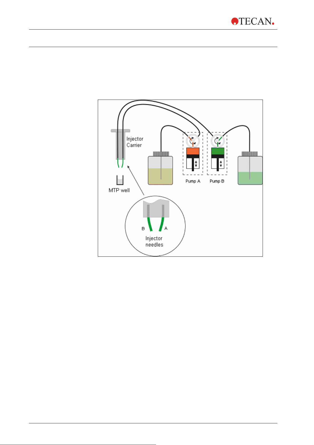
200 can be optionally equipped with an injector module consisting of
Figure 2-1: Schematic view of the injector module
There are up to two pumps available for the
• Pump A feeds injector needle A
• Pump B feeds injector needle B
The
infinite® 200 can be equipped with one pump (pump A) or two pumps
(pumps A and B).
One Injector Option (one pump): An
allows injections in any SBS-conform microplate well types, in which the well-size
is equal to or larger than an SBS standard 384-well plate.
Two Injector Option (two pumps): Some applications, such as flash
luminescence reactions or dual reporter gene assays require the injection of two
independent liquids into the same well; therefore, Tecan Austria offers a twoinjector option.
infinite® 200 (see Figure 2-1 above):
infinite® 200 equipped with one pump
20 Instructions for Use for infinite® 200 No. 30017581 Rev. No. 1.4 2008-07
Page 21

2. General Description
2.3.1 Measurement with Injectors
The injectors of the infinite
modes: Fluorescence Intensity top and bottom, Time Resolved Fluorescence,
Absorbance, Flash and Glow Type Luminescence and Dual Color Luminescence.
As the measurement position is not the same as the injector position, a short time
delay (approx. < 0.5 s) between injection and reading occurs.
For details on how to set up a measurement with injectors please refer to chapter
2.4.1 i-Control and Injectors.
2.3.2 Storage Bottles
The injector box may hold up to two 125 ml bottles. An adapter for smaller tubes
allows using tubes of different size (1.5 ml, 15 ml, 50 ml tubes etc.)
The standard bottle set supplied with the Injector option consists of:
• One 125 ml bottle and one 15 ml bottle for the “One Injector option” (one
pump) or
• Two 125 ml bottles and two 15 ml bottles for the “Two Injectors option” (two
pumps).
®
200 can be used with the following measurement
Figure 2-2: Storage bottles and adapter for smaller tubes
2008-07 Instructions for Use for infinite® 200 No. 30017581 Rev. No. 1.4 21
Page 22

2. General Description
2.3.3 Injector/Injector Carrier
The carrier, which includes the injector needles, can be easily removed from the
instrument for priming or washing the system and for optimizing the injection
speed.
Figure 2-3: Injector carrier
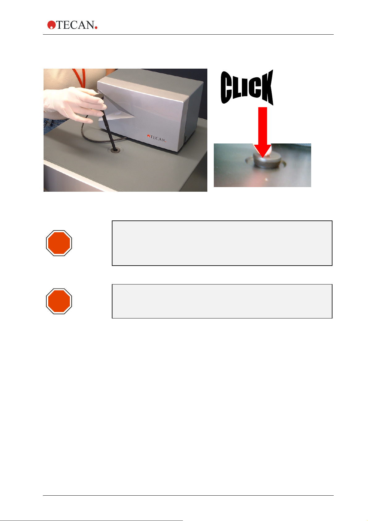
When using the injector during a measurement or for just dispensing a plate the
injector carrier must be inserted correctly into the instrument. Remove the injector
dummy and insert the carrier into the injector port. Press the carrier softly into the
injector port until you hear a clicking noise.
The instrument contains an injector sensor that checks that the position of the
injector carrier for the actions ‘inject’ and ‘dispense’ is correct.
If the injector carrier is not inserted correctly the injector sensor does not
recognize the inserted carrier and neither dispensing nor injection is possible. On
the other hand actions like washing and priming are enabled although the injector
carrier is inserted. Therefore always make sure that the injector carrier is in the
service position for washing and priming.
22 Instructions for Use for infinite® 200 No. 30017581 Rev. No. 1.4 2008-07
Page 23
2. General Description
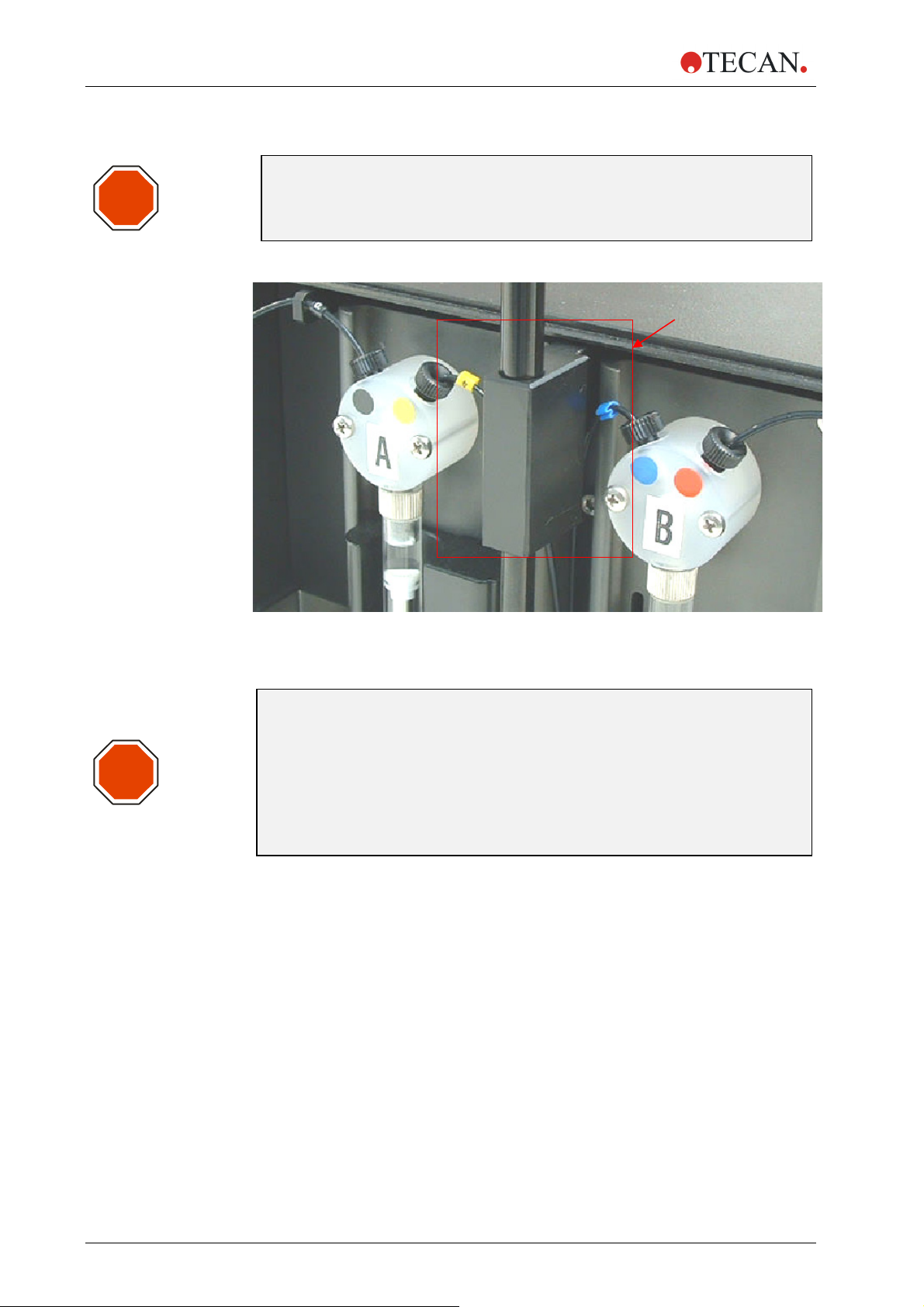
STOP
Picture 2-1: Inserting the injector carrier into the injector port
Caution
The injector carrier must be in the service position
for washing und priming.
Prime and Wash must not be performed
when the injector is in the instrument!
STOP
Caution
If the injector carrier is not inserted correctly in the injector port, the
injector sensor will not detect the inserted injector and therefore
washing and priming will be enabled, which can damage the instrument.
2008-07 Instructions for Use for infinite® 200 No. 30017581 Rev. No. 1.4 23
Page 24
2. General Description
The dead volume of the injection system (injector needles, syringes, valves and
tubing) is approximately 100 µl after ‘backflush’ for each syringe. The function of
backflush is to return any unused reagent to the reservoir bottles. The injection
speed can be adjusted via the software to allow for good mixing of reagents. The
optimum injection speed depends on the assay parameters, such as viscosity of
fluids, the plate format and the measuring behavior of the liquids.
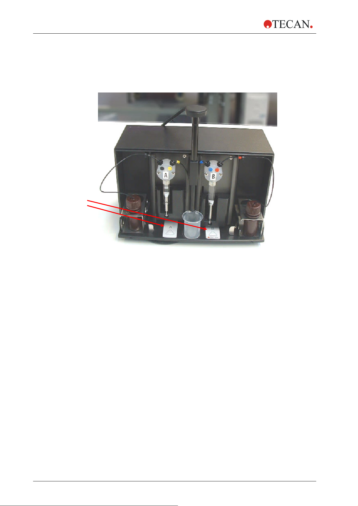
Prime/Wash buttons
for injectors A and B
Figure 2-4: Injector-box with injector in ‘service position’
Before starting a measurement make sure that:
The tubes are clean. If not please refer to chapter 2.3.4 Priming and
Wa
shing of the infinite
®
200 for details how to clean the injector system.
The injector tubes are correctly inserted into the storage bottles and fixed.
The injector system is primed. It is not possible to start a measurement
without priming the system.
When priming the system:
1. Check the tubes for leaks.
2. Check the tubes for kinks.
3. Make sure that the injector needles are not twisted.
If the tubes require replacement for any reason, after the tubes have been
changed do not forget to perform washing and priming before starting a
measurement.
24 Instructions for Use for infinite® 200 No. 30017581 Rev. No. 1.4 2008-07
Page 25

2. General Description
2.3.4 Priming and Washing of the infinite® 200
Caution
The injector carrier must be in the service position
STOP
The initial filling step of the injector system (priming) as well as the cleaning step
of the injector system (washing) must take place outside of the instrument. For
these procedures the injector carrier is removed from instrument and put into the
service position of the injector box. For priming and washing steps of the injector
system, a default setting for injection speed and volume dispensed is provided. If
required the priming parameters can be adjusted in the injector control window of
the i-Control software.
The prime volume depends on the tubing length. Two types of injector tubing are
available: ‘long’: 105 cm, and ‘short’: 80 cm.
For the initial filling step of the injector system (priming) it is recommended to use
at least 2000 µl to remove all air bubbles from the injection system. The minimum
prime volume is therefore 2 ml. To save precious reagents, this initial filling step
can be performed with distilled water. To replace the water with the required
reagent, a second priming step is needed. For this second priming step, the
priming volume can be reduced to approx. 1500 µl.
Prime and Wash must not be performed
when the injector is in the instrument!
for washing und priming.
2008-07 Instructions for Use for infinite® 200 No. 30017581 Rev. No. 1.4 25
Page 26
2. General Description
Caution
STOP
A prime volume below 2 ml in an empty system may result in incomplete
filling of the system, and therefore may negatively affect assay
performance.
Service-Position
STOP
Figure 2-5 ‘Service Position’ of the injectors. The injectors are removed from the
carrier slot and inserted into the holder of the injector carrier system.
Caution
Do not touch the injector needles. They can become easily bent or
misaligned, which can cause injection problems or damage the
instrument.
If the injector carrier is not inserted correctly in the injector port, the
injector sensor does not detect the inserted injector and therefore
washing and priming is enabled which can damage the instrument. In
addition to this, the actions ‘dispense’ and ‘inject’ will not be possible.
26 Instructions for Use for infinite® 200 No. 30017581 Rev. No. 1.4 2008-07
Page 27
Priming
2. General Description
Before the injection system can be used, an initial filling step (priming) is needed
to remove all air and to completely fill the system with liquid.
It is recommended to perform a washing step before priming.
Priming can be performed by using the i-Control software or by using the
hardware buttons on the injector box:
Priming procedure (general):
1. Fill the storage bottles with the necessary reagents and insert the feeding
tube(s). Make sure, that the tube(s) reaches the bottom of the bottle.
2. Remove the injector from the carrier slot and insert it into the service
position of the injector box.
3. Put an empty container under the injector.
Priming procedure (i-Control):
1. Adjust parameters at the prime tab of the injector maintenance dialog box
in the settings menu
2. Activate the priming procedure by clicking the ‘Start prime’ button in the
injector maintenance dialog box.
3. Visually inspect the syringes for air bubbles. Any bubbles should be
removed after priming to ensure good injection performance.
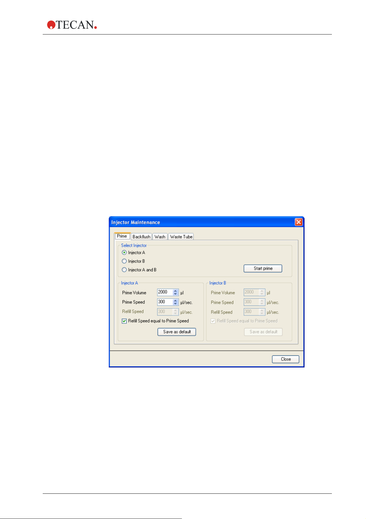
Prime
Select one of the injectors Injector A or Injector B or Injector A and B.
Select the ‘Prime Volume’ (5 -60000 µl)
Select the ‘Prime Speed’ (100 - 300 µl/sec).
Select the ‘Refill Speed’ (100 – 300 µl/sec.) or select ‘Refill Speed equal to
Prime Speed’.
Start prime by clicking the ‘Start prime’ button.
Click the ‘Save as default’ button to save the selected settings to the
corresponding hardware button (A or B) on the injector box. When using the
hardware buttons for priming, these settings will be applied.
Select ‘Close’ to exit the dialog box
2008-07 Instructions for Use for infinite® 200 No. 30017581 Rev. No. 1.4 27
Page 28

2. General Description
Priming Procedure (hardware button):
Priming can also be performed without using the software. Priming parameters
can be stored on the injector by clicking Save as Default on the Prime tab of the
Injector Maintenance dialog box of the i-Control software (in the Settings menu,
click Injectors... and the Injector Maintenance dialog box appears). Press the
Prime/Wash button on the injector box to start the priming sequence using the
default parameters, (see Figure 2-4: Injector-box with injector in ‘service position’,
page 24). The injector must be connected the inst
be switched on. Start the prime procedure by pressing the Prime/Wash button for
less than 3 seconds.
Visually inspect the syringes for air bubbles. Any bubbles should be removed
after priming to ensure good injection performance.
After a successful priming procedure, reinsert the injector into the instrument.
Close the lid of the pump module completely before starting a measurement. The
injectors are now ready to use.
When starting a measurement with the actions ‘injection’ or ‘dispense’, 5 µl of
liquid are dispensed into a disposable container on the plate carrier before
starting ‘injection’ or ‘dispense’. This initial dispense step makes sure that the
injection/dispense conditions are equal for each well.
rument and the instrument must
Caution
STOP
Close the lid of the pump module (injector box) completely before
starting a measurement.
Priming Example – Operational Sequence of Pump System
The following example describes the operational sequence of the pump system
when performing a prime step with 500 µl.
• The system is already washed (syringe is empty; piston in upper position):
• The first action is always that the syringe has to be filled completely with
liquid. The piston therefore moves down to the lowest position to fill
syringe completely (volume 1 ml).
• Now the system prepares for the priming step. The piston makes space
for the selected prime volume: The selected prime volume is ejected:
500 µl – the piston moves up.
• The piston moves down again to prime the syringe with the selected
volume. The syringe is now completely filled.
• After finishing priming the last action is to eject 5 ml. This step makes
sure that the injection/dispense conditions are equal for each well (for
details please refer to ‘Waste tub’)
Be aware that for selected prime volume of 500 µl, 1500 µl liquid are needed
due to the initial filling step of the syringes.
• The system is not washed (the syringe is partly filled with liquid, the piston is
not in the upper position):
• The first action is always that the syringe is emptied. The piston therefore
moves up to the highest position to empty the syringe.
• The next actions are similar to case 1.
Note
For a selected prime volume of 500 µl, a minimum volume of 1500 µl of
28 Instructions for Use for infinite® 200 No. 30017581 Rev. No. 1.4 2008-07
liquid is required to perform a complete priming step.
Page 29
2. General Description
Reagent Backflush
Reagent backflush allows reagents in the tubing system to be pumped back into
storage bottles. This action can be performed optionally prior to washing the
injector system to minimize the dead volume.
Reagent backflush procedure:
1. Remove the injector carrier from the instrument and insert the injector
carrier into the service position of the injector box.
2. Insert the feeding tubing into the appropriate storage bottle.
3. Adjust parameters on the Backflush tab of the Injector Maintenance
dialog box in the Settings menu
4. Start the reagent backflush procedure by clicking Start backflush.
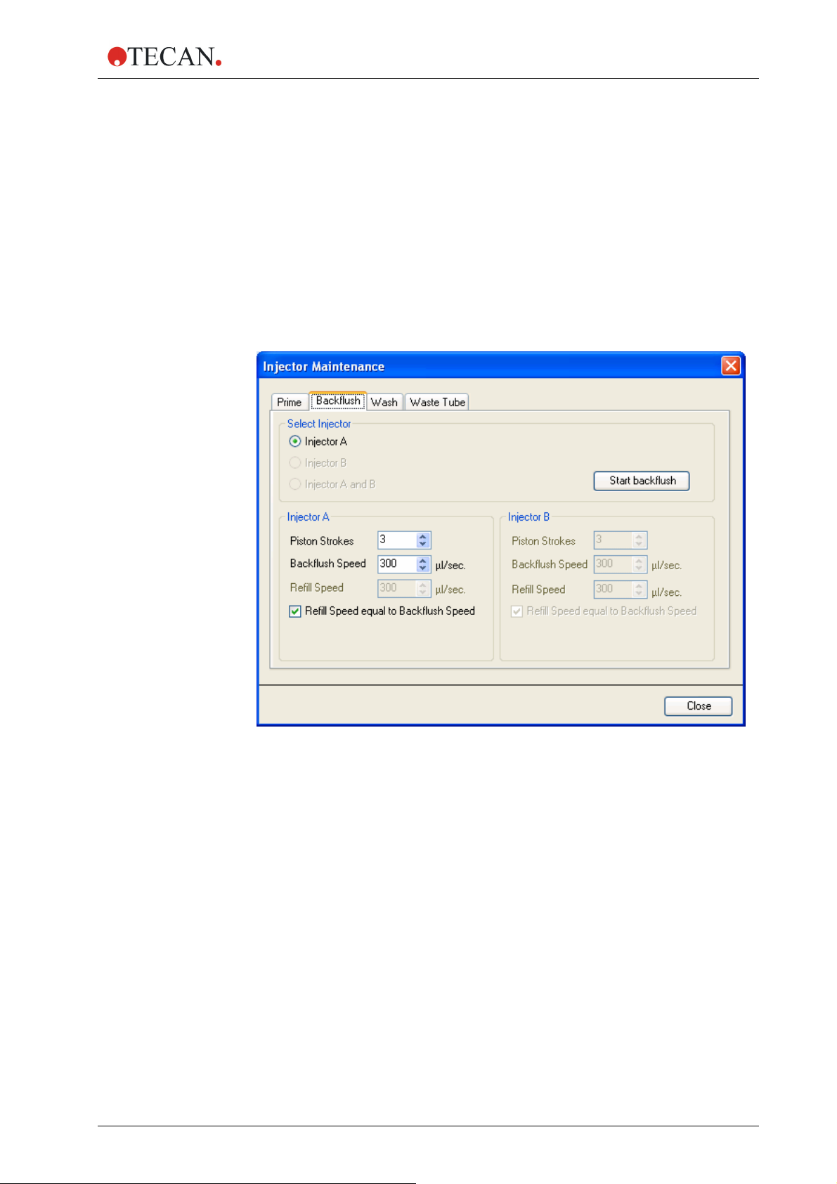
Backflush
Select one of the injectors Injector A or Injector B or Injector A
and B (only ‘primed’ injectors are available for ‘backflush’).
Select the Piston Strokes (1 – 60; 1 stroke equals 1 ml)
Select the Backflush Speed (100 - 300 µl/sec).
Select the ‘Refill Speed’ (100 – 300 µl/sec.) or select the Refill
Speed equal to Backflush Speed check box.
Click Start backflush to start the reagent backflush procedure.
Click Close to exit the dialog box.
2008-07 Instructions for Use for infinite® 200 No. 30017581 Rev. No. 1.4 29
Page 30

2. General Description
Caution
STOP
Do not perform backflush when the injector is in the instrument!
The injector carrier must be in the service position
for the action ‘backflush’.
Washing
Before the instrument is switched off, it is recommended to perform a wash
procedure to clean the injector system.
Wash procedure:
Washing can be performed by using the i-Control software or by using the
hardware buttons on the injector box.
Washing (general procedure):
1. Fill the storage bottles with the appropriate wash reagents (distilled water,
70 % ethanol, …) and insert the feeding tube(s). Make sure, that the
tube(s) reaches the bottom of the bottle.
2. Remove the injector from the carrier slot and insert it into the service
position of the injector box.
3. Put an empty container under the injector.
30 Instructions for Use for infinite® 200 No. 30017581 Rev. No. 1.4 2008-07
Page 31

Washing (i-Control):
2. General Description
1. Adjust the parameters on the Wash tab of the Injector Maintenance
dialog box in the Settings menu
2. Start the washing procedure by clicking the Start wash.
Wash
Select one of the injectors Injector A or Injector B or
Injector A and B.
Select the Piston Strokes (1 – 60; 1 stroke equals 1 ml)
Select the Wash Speed (100 - 300 µl/sec).
Select the Refill Speed (100 – 300 µl/sec.) or select Refill
Speed equal to Wash Speed.
Click Start wash to start the wash procedure.
Click Close to exit the dialog box.
2008-07 Instructions for Use for infinite® 200 No. 30017581 Rev. No. 1.4 31
Page 32

2. General Description
Washing (hardware buttons):
Washing can also be performed without using the software. Washing parameters
can be stored on the injector by clicking Save as Default on the Wash tab of the
Injector Maintenance dialog box (in the Settings menu, click Injectors... and the
Injector Maintenance dialog box appears) of the i-Control software. Press the
Prime/Wash button on the injector box to start the washing sequence using the
default parameters. (see Figure 2-4: Injector-box with injector in ‘service position’,
page 24). The injector must be connected the inst
be switched on. Start the wash procedure by pressing and holding the
Prime/Wash button for more than 3 seconds.
rument and the instrument must
Caution
STOP
The injector carrier must be in the service position
for the action ‘wash’.
Do not perform washing when the injector is in the instrument!
Important
STOP
Be sure to run a final wash procedure with distilled water and empty the
injector system. For good care and lifetime fill the injector system with
liquid (water) before turning off the instrument.
STOP
STOP
STOP
Important
Please see the corresponding reagent kit for advice on how to remove
the substrate completely from the tubing system.
Important
Take good care of the injectors, because if they are damaged the
accuracy of dispensing may be affected. This can result in damage to
Injector needles can be replaced by exchanging the injector carrier
together with the corresponding tubing.
the instrument.
Note:
Important
The button(s) on the injector box include two functions:
• Press the button for less than 3 seconds to start PRIME.
• Press the button for more than 3 seconds to start WASH.
The parameters have to be set in the i-Control software.
32 Instructions for Use for infinite® 200 No. 30017581 Rev. No. 1.4 2008-07
Page 33

Waste Tub
2. General Description
When starting a measurement with the actions ‘injection’ or ‘dispense’, 5 µl of
liquid are dispensed into a disposable container on the plate carrier before
starting ‘injection’ or ‘dispense’.
This initial dispense step makes sure that the injection/dispense conditions are
equal for each well. This special dispense step depends on the selected refill
mode selected on the injector or dispense strip (see chapter 2.4.1 i-Control and
tors for details).
Injec
When using ‘standard’ refill mode, the dispense step is performed after each refill.
When using ‘refill for every injection’ the dispense step is only performed once
when starting the measurement.
The disposable waste container (waste tub) must therefore be emptied from time
to time. The maximum filling volume is 1.5 ml. An internal counter checks the
dispensed liquid volumes and the software alerts the user when it is time to
empty the waste tub.
Picture 2-2: Waste tub on plate carrier
2008-07 Instructions for Use for infinite® 200 No. 30017581 Rev. No. 1.4 33
Page 34

2. General Description
Waste tub:
Click the ‘Empty Waste tub’ button and the plate carrier will move out
automatically. Remove the waste tub and empty the contents. After the waste tub
has been emptied place it back on the plate carrier. The i-Control software will
alert you when the waste tub needs to be emptied again.
STOP
STOP
Caution
Place the waste tub on the plate transport before starting a
measurement with the actions ‘injection’ and/or ‘dispense’.
Caution
It is recommended to empty the waste tub before starting a
measurement and to empty it at least once a day.
WARNING
BIOLOGICAL HAZARDS CAN BE ASSOCIATED WITH THE WASTE
MATERIAL (MICROPLATE) OF THE PROCESSES
RUN ON THE infinite
TREAT THE USED MICROPLATE, OTHER DISPOSABLES, AND ALL
SUBSTANCES USED, IN ACCORDANCE WITH GOOD LABORATORY
PRACTICE GUIDELINES.
INQUIRE ABOUT APPROPRIATE COLLECTING POINTS AND APPROVED
METHODS OF DISPOSAL IN YOUR COUNTRY, STATE OR REGION.
®
200.
34 Instructions for Use for infinite® 200 No. 30017581 Rev. No. 1.4 2008-07
Page 35

2. General Description
2.3.5 Injector Cleaning and Maintenance
The required maintenance may vary with your application. The following
procedures are recommended for optimal performance and maximum life of the
injector system.
Daily Maintenance:
If not otherwise stated by the manufacturer of the kit to be used, the following
tasks must be performed at least daily:
• Inspect the pump(s) and tubing for leaks.
• Flush the whole system thoroughly with distilled or deionized water after
each use and when the pump is not in use. Failure to do so can result in
crystallization of reagents. These crystals can damage the syringe seal
and valve plug resulting in leakage.
STOP
Do not allow the pump(s) to run dry for more than a few cycles.
Weekly/Periodical Maintenance:
The injector system (tubing, syringes, injector needles) must be cleaned weekly
to remove precipitates and eliminate bacterial growth:
Follow these steps to clean the pump/injector system with 70 % EtOH (ethanol):
1. Depending on the user’s application flush thoroughly the system with
buffer or distilled water before washing with 70 % EtOH.
2. Prime the pump with 70 % EtOH with syringes fully lowered for 30
minutes.
3. After the 30-minute period, cycle all the fluid from the syringe and tubing
into a waste container.
4. Wash the pump/injector system with 70 % EtOH
5. Wash the pump/injector system with distilled or deionized water
6. Prime the pump/injector system with distilled water. Leave the fluid
pathway filled for storage.
7. Clean the end of the injector needles with a cotton swab soaked in 70 %
ethanol or isopropanol.
Caution
WARNING
RISK OF FIRE AND EXPLOSION!
ETHANOL IS FLAMMABLE AND WHEN IMPROPERLY HANDLED CAN
2008-07 Instructions for Use for infinite® 200 No. 30017581 Rev. No. 1.4 35
LEAD TO EXPLOSIONS. PROPER LABORATORY SAFETY
PRECAUTIONS MUST BE OBSERVED.
Page 36

2. General Description
2.3.6 Injector Reagent Compatibility
The injector system of the infinite® F/M200 consist of the following materials:
• Teflon (PTFE): Tubing, valve plug, seal
• KelF: Valve body
• SC05: Injector needles
Please refer to the following list for reagent compatibility. The column ‘Rating’
indicates the compatibility with the reagents listed in the ‘Chemical’ column.
Rating ‘A’ indicates a good compatibility with the injector system. Chemicals with
a rating ‘D’ must not be used with the infinite
damage the injector system.
Chemical Rating
Acetic Acid < 60% A
Acetonytrile A
Butyl Amine D
Carbon Tetrachloride (dry) D
Chloroform A
Diethyl Ether D
Dimethyl Formamide A
Ethanolamine D
Ethanol A
Ethylene Diamine D
Furfural D
Hexane A
Hydrofluoric Acid D
Methanol (Methyl Alcohol) A
Monoethanolamine D
Potassium Hydroxide (Caustic Potash) D
Potassium Hypochlorite D
Sodium Hydroxide D
Sodium Hypochlorite D
Concentrated Sulfuric Acid D
Diluted Sulfuric Acid (Concentration ≤ 1 N) A
Tetrahydrofuran A
Water, Deionized A
Water, Distilled A
Water, Fresh A
®
injectors. They will severely
36 Instructions for Use for infinite® 200 No. 30017581 Rev. No. 1.4 2008-07
Page 37

STOP
STOP
2. General Description
Caution
The information in this table has been supplied to Tecan Austria by
other reputable sources and is to be used ONLY as a guide in selecting
equipment for appropriate chemical compatibility. Before permanent
installation, test the equipment with the chemicals and under the
specific conditions of your application.
Caution
Variations in chemical behaviour during handling due to factors such as
temperature, pressure and temperature, pressure, and concentration
can cause equipment to fail, even though it passed an initial test.
SERIOUS INJURY MAY RESULT. Use suitable guards and/or personal
protection when handling chemicals.
2008-07 Instructions for Use for infinite® 200 No. 30017581 Rev. No. 1.4 37
Page 38

2. General Description
2.4 Software
The infinite
instrument and includes an online-help file and a printed Instructions for Use. The
software is formatted as a self-extracting archive on CD-ROM.
For advanced data reduction and full regulatory compliance with CFR 2 part 11
guidelines, The Magellan software can be used to control the
more information, contact your local Tecan representative).
®
200 is delivered with the i-Control software, for operating the
2.4.1 i-Control and Injectors
When using the injector, two modes are available:
• Dispense: The dispense mode allows liquid to be dispensed plate-wise
into the selected wells
• Injection: This mode must be used in combination with a measurement
strip. The injection is performed in a well-wise mode.
Dispense Mode
The dispense settings can be adjusted via the software:
infinite® 200. (For
Dispense
38 Instructions for Use for infinite® 200 No. 30017581 Rev. No. 1.4 2008-07
Select Injector: Injector A and/or Injector B can be selected.
Speed: The injection speed is selectable from 100 – 300 µl/sec for each
injector.
Select ‘Refill speed’ from 100 – 300 µl/sec. for each injector or select
‘Refill Speed equal to Dispense Speed’.
Select refill mode ‘Standard’, if refill should be performed when syringe is
empty (multiple dispense steps are performed before refilling, refill occurs
after dispensing approx. 800 µl).
Select ‘Refill for every dispense’ if refill should be performed for every
dispense step.
Page 39

2. General Description
Using the Dispense Strip:
Plate
Part of the plate
Dispense
Dispense volume
Select an appropriate plate type
Optional;
Select the wells to be dispensed
Set up the dispense parameters.
If both injectors are selected, all wells are first dispensed with
injector A and then with injector B.
The dispense strip does not require an additional measurement
strip.
The injection volume depends on the microplate type. The plate
definition files include a so-called working volume. This working
volume defines the maximum volume to be dispensed into the
selected microplate. Therefore, always make sure that the
selected plate definition file contains the correct setting for the
working volume. The maximum dispense volume is
800 µl/dispense strip. If volumes greater than 800 µl are to be
dispensed (e.g. into 6-well plates), more than one dispense strip
has to be used.
2008-07 Instructions for Use for infinite® 200 No. 30017581 Rev. No. 1.4 39
Page 40

2. General Description
Injection Mode
The injection settings can be adjusted via the software:
Injection
Select Injector:
Injector A or Injector B can be selected. It is not possible to select
both injectors on one strip. If a measurement with two injectors is to
be performed, two injector strips are necessary.
Speed: The injection speed is selectable from 100 – 300 µl/sec for
each injector.
Select a ‘Refill speed’ from 100 – 300 µl/sec. for each injector or
check the ‘Refill Speed equal to Injection Speed’ box.
Select refill mode ‘Standard’ if refill should be performed when
syringe is empty (multiple injection steps are performed before
refilling, refill occurs after dispensing approx. 800 µl). Select ‘Refill
for every injection’ if refill should be performed for every injection
step.
Injection
volume
The injection volume depends on the microplate type. The plate
definition files include a so-called working volume. This working
volume defines the maximum volume to be injected into the
selected microplate. Therefore, always make sure that the selected
plate definition file contains a correct setting for the working volume.
The maximum injection volume is 800 µl/injection strip. If volumes
greater than 800 µl are to be injected (e.g. into 6-well plates), more
than one injection strip has to be used.
40 Instructions for Use for infinite® 200 No. 30017581 Rev. No. 1.4 2008-07
Page 41

2. General Description
Using the Injection Strip:
Plate
Part of the plate
Well
Injection
Measurement strip
(Example
Absorbance)
Select an appropriate plate type.
Optional;
Select the wells to be dispensed
The well strip is mandatory.
Injection is only possible with a ‘well’ strip. This strip ensures that
the following indented strips are performed well-wise.
Set up the injection parameters.
Only one injector can be selected per strip. If both injectors are
required or one injector will perform two injections, an additional
injection strip has to be inserted.
It is mandatory to use at least one measurement strip in
combination with the injection strip. The position of the
measurement strip(s) (before and/or after the injection strip)
depends on the application and is therefore user-selectable.
Note
Make sure that the corresponding Working Volume value in your plate
definition file is higher than the volume used for injection.
2008-07 Instructions for Use for infinite® 200 No. 30017581 Rev. No. 1.4 41
Page 42

2. General Description
Wait Strip
A Wait time (delay or settle time) can be inserted into the procedure.
Wait time
Options
Select a time in hh:mm:ss from 00:00:01 up to 23:59:59
If ‘Wait for injection’ is selected, the wait time includes the injection
time.
If ‘Wait for injection’ is NOT selected, the wait time is added to the
injection time.
42 Instructions for Use for infinite® 200 No. 30017581 Rev. No. 1.4 2008-07
Page 43

2. General Description
2.4.2 i-Control Examples
Example 1: Dual Luciferase Assay™ (Promega Corp.)
For assay details please refer to www.promega.com.
Plate
Part of the plate
Well
Injection (1)
Wait (Timer)
Luminescence (1)
Injection (2)
Wait (Timer)
Luminescence (2)
Move Plate
Select an appropriate plate type. For luminescence measurements, white
microplates are recommended. For this example, a white 96-well plate was
selected.
(Not shown); can be optionally selected if only part of the plate is to be
processed.
Mandatory for measurements with ‘injection’
Injector A injects 100 µl with speed 200 µl/sec., refill mode: standard
2 s wait time
Luminescence measurement with 10 s integration time, attenuation ‘none’
Injector B injects 100 µl with speed 200 µl/sec., refill mode standard
2 s wait time
Luminescence measurement with 10 s integration time, attenuation ‘none’
Plate is moved out after finishing all wells
2008-07 Instructions for Use for infinite® 200 No. 30017581 Rev. No. 1.4 43
Page 44

2. General Description
Example 2: Enliten® ATP Assay System Bioluminescence Detection Kit for ATP (Promega Corp.)
For assay details please refer to www.promega.com.
Plate
Part of the plate
Well
Injection
Wait (Timer)
Luminescence
Move Plate
Select an appropriate plate type. For luminescence
measurements, white microplates are recommended. For
this example, a white 96 well plate was selected.
(Not shown); can be optionally selected if only part of the
plate should be processed
Mandatory for measurements with ‘injection’
Injector A injects 100 µl with speed 100 µl/sec., refill mode:
standard
2 s wait time
Luminescence measurement
with 10 s integration time, attenuation ‘none’
Plate is moved out after finishing all wells
44 Instructions for Use for infinite® 200 No. 30017581 Rev. No. 1.4 2008-07
Page 45

2. General Description
Example 3: Measurement of Ca2+ sensitive probes – Fura-2
Plate
Part of the plate
Well
Kinetic Cycle
Kinetic condition
Injection
Fluorescence Intensity (1)
Fluorescence intensity (2)
Move Plate
Select an appropriate plate type. For fluorescence
measurements, black microplates are recommended.
For this example, a black 96 well plate was selected.
(Not shown), can be optionally selected if only part of the
plate should be processed
Mandatory for measurements with ‘injection’
Select the number of necessary cycles
This strip allows actions to be performed once in a kinetic
run at a certain cycle. The intended injection strip below it
is only processed once at the selected cycle.
Injector A injects 20 µl with speed 200 µl/sec., refill mode:
not selectable; injection is performed at cycle 5 (defined
by kinetic condition strip)
Select the appropriate parameters for the first label:
Excitation wavelength: 380 nm, Emission wavelength:
510 nm; number of flashes: 25; integration time: 40; gain:
manual
Select the appropriate parameters for the second label:
Excitation wavelength: 340 nm, Emission wavelength:
510 nm; number of flashes: 25; integration time: 40; gain:
manual
Plate is moved out after finishing all wells
2008-07 Instructions for Use for infinite® 200 No. 30017581 Rev. No. 1.4 45
Page 46

2. General Description
Example 4: Measurement of Ca2+ sensitive probes – Indo-1
Plate
Part of the plate
Well
Kinetic Cycle
Kinetic condition
Injection
Fluorescence Intensity (1)
Fluorescence intensity (2)
Move Plate
Select an appropriate plate type. For fluorescence
measurements, black microplates are recommended.
For this example, a black 96 well plate was selected.
(Not shown); can be optionally selected if only part of the
plate should be processed
Mandatory for measurements with ‘injection’
Select the number of necessary cycles
This strip allows actions to be performed once in a kinetic
run at a certain cycle. The intended injection strip below it
is only processed once at the selected cycle.
Injector A injects 20 µl with speed 200 µl/sec., refill mode:
not selectable; injection is performed at cycle 5 (defined
by kinetic condition strip)
Select the appropriate parameters for the first label:
Excitation wavelength: 340 nm, Emission wavelength:
410 nm; number of flashes: 25; integration time: 40; gain:
manual
Select the appropriate parameters for the second label:
Excitation wavelength: 340 nm, Emission wavelength:
480 nm; number of flashes: 25; integration time: 40; gain:
manual
Plate is moved out after finishing all wells
46 Instructions for Use for infinite® 200 No. 30017581 Rev. No. 1.4 2008-07
Page 47

3. Installation
3. Installation
3.1 Unpacking and Inspection
The delivered packaging includes the following items:
• CABLE USB 2.0 A/B 1.8 M Black with housing receptacle ferrite
• CDROM
• OOB Quality Report
• Transport lock (mounted)
• Instructions for Use
• Final test protocol
infinite® F200 packaging includes additionally the following items:
The
• Accessory Box
• Filter stop rings (8)
• Filter assembly tool
• Plastic tweezers
• Filter slide
infinite® F200/infinite® M200
STOP
The injector module packaging for 1 injector includes the following items:
• Bottle holder
• Beaker for priming
• 125 ml bottle brown
• Injector dummy (mounted)
• Waste tub
• 15 ml bottle
The second injector comes with the following items:
• Bottle holder
• Beaker for priming
• 125 ml bottle brown
• Waste tub
• 15 ml bottle
Caution
The reader has been tested with the supplied USB cable. If another USB
cable is used, Tecan Austria cannot guarantee the correct performance
of the instrument.
2008-07 Instructions for Use for infinite® 200 No. 30017581 Rev. No. 1.4 47
Page 48

3. Installation
3.1.1 Unpacking Procedure
1. Visually inspect the container for damage before it is opened.
Report any damage immediately.
2. Select a location to place the instrument that is flat, level, vibration free,
away from direct sunlight, and free from dust, solvents and acid vapors.
Allow at least 10 cm distance between the back of the instrument and the
wall or any other equipment. Ensure that the plate carrier cannot be
accidentally hit when moved out. Ensure that the main switch and the main
cable can be reached at all times and are in no way obstructed.
3. Place the carton in an upright position and open it.
4. Lift the instrument out of the carton and place it in the selected location.
Take care when lifting the instrument and ensure that it is held on both
sides.
5. Visually inspect the instrument for loose, bent or broken parts.
Report any damage immediately.
6. Compare the serial number on the rear panel of the instrument with the
serial number on the packing slip.
Report any discrepancy immediately.
7. Check the instrument accessories against the packing list.
8. Save packing materials and transport locks (see next section) for further
transportation purposes.
STOP
STOP
STOP
STOP
WARNING
THE infinite
®
200 IS A PRECISION INSTRUMENT AND WEIGHS FULLY
EQUIPPED APPROX. 16 KG.
Caution
The maximum load for the infinite
must be distributed evenly across the entire surface of the cover.
®
200 cover is 16 kg, however the load
Caution
The maximum load for the infinite
®
200 plate transport is 100 g.
Caution
Allow at least 10 cm distance between the back of the instrument and
the wall or any other equipment.
Caution
The instrument must be placed in a location away from direct sunlight.
Illumination > 500 lux can negatively influence luminescence
measurements.
48 Instructions for Use for infinite® 200 No. 30017581 Rev. No. 1.4 2008-07
Page 49

3. Installation
3.2 Removal of the Transport Locks
STOP
Caution
Remove the transport lock before operating the instrument.
The instrument is delivered with the plate carrier and filter carrier/cuvette carrier
locked into place, so that they cannot be damaged. Before the instrument can be
used, the transport locks must be removed using the following procedure:
1. Ensure that the instrument is disconnected from the main power supply.
2. Open the plate carrier door and filter carrier/cuvette carrier door.
3. Remove the screw from the transport lock, which extends into the filter
carrier/cuvette carrier compartment from the plate carrier compartment
(left transport lock in picture above).
2008-07 Instructions for Use for infinite® 200 No. 30017581 Rev. No. 1.4 49
Page 50

3. Installation
4. Loosen the screw from other transport lock, which is only in the plate
carrier compartment (right transport lock in picture above).
5. Pull the plate carrier out manually.
6. Remove the screw from the transport lock, which is only in the plate
carrier compartment (right transport lock in picture above).
7. Slide the transport locks off of the pins and remove them from the
plate carrier.
STOP
8. Save the transport locks for further transportation purposes.
Caution
Save packing materials and transport locks for further transportation
purposes. The infinite
packaging and installed transport locks.
®
200 must be shipped only with the original
50 Instructions for Use for infinite® 200 No. 30017581 Rev. No. 1.4 2008-07
Page 51

3. Installation
3.3 Transport and Storage
3.3.1 Transport
The infinite
transport locks. Before shipping the instrument, it must be thoroughly disinfected
(see 9.3 Instrument Disinfection).
®
200 must be shipped using the original packing and installed
3.3.2 Storage
Before storing the instrument the injectors must be rinsed using a wash
procedure (see 2.3.4 Priming and Washing of the infi
to store the instrument that is flat, level, vibration free, away from direct sunlight,
and free from dust, solvents and acid vapors
Storage Specifications
Temperature - 20 °C to + 60 °C -4 °F to + 140 °F
Relative Humidity < 90 % non condensing
3.4 Power Requirements
The instrument is auto sensing and it is therefore not necessary to make any
changes to the voltage range. Check the voltage specifications on the rear panel
of the instrument and ensure that the voltage supplied to the instrument is correct
to this specification.
The voltage range is 100-120/220-240V.
If the voltage is not correct, please contact your distributor.
nite® 200). Select a location
STOP
Caution
Do not use the instrument if the voltage setting is not correct.
If the instrument is switched ON with the incorrect voltage
setting it will be damaged.
WARNING
IF THE INSTRUCTIONS GIVEN IN THIS DOCUMENT ARE NOT
CORRECTLY PERFORMED, THE INSTRUMENT WILL EITHER BE
DAMAGED OR THE PROCEDURE WILL NOT BE PERFORMED
CORRECTLY AND THE SAFETY OF THE INSTRUMENT IS NOT
GUARANTEED.
2008-07 Instructions for Use for infinite® 200 No. 30017581 Rev. No. 1.4 51
Page 52

3. Installation
3.5 Switching the Instrument On
Caution
STOP
STOP
Before the instrument is switched on for the first time after installation,
it should be left to stand for at least 3 hours, so there is no possibility of
condensation causing a short circuit.
1. Ensure the computer is switched OFF and the instrument's main power
switch on the back panel of the instrument is in the OFF position.
2. Connect the computer to the instrument with the delivered USB interface
cable.
3. Insert the power cable into the main power socket (with protective ground
connection) on the back panel of the instrument.
4. All connected devices must be approved and listed as per IEC 60950-1
Information Technology Equipment – Safety or equivalent local standards.
5. Switch the instrument ON using the main power switch on the back panel of
the instrument.
Caution
The reader has been tested with the supplied USB cable. If another USB
cable is used, Tecan Austria cannot guarantee the correct performance
of the instrument.
52 Instructions for Use for infinite® 200 No. 30017581 Rev. No. 1.4 2008-07
Page 53

Rear View
3. Installation
1
10
INJECTOR
3
4
INFINITE
REF
3001605
SN
XXXXXXXXX
AC 100-120 / 220-240, 50/60
JJJJ-
7
2
8
USB
ATTENTION !
REMOVING OR BREAKING
THIS SEAL VOIDS YOUR
9
WARRANTY !
6
5
1 Instrument Fan
2 Power Supply Fan
3 Main Power Switch
STOP
4 Main Power Socket
5 Label – Technical Inspection Agency
6 Label – Options/Configuration
7 Name Plate
8 Warranty Label
9 USB Connection
10 Injector Connection
Caution
Only Tecan authorized service technicians are allowed to open the
instrument. Removing or breaking the warranty seal voids the warranty.
2008-07 Instructions for Use for infinite® 200 No. 30017581 Rev. No. 1.4 53
Page 54

Page 55

4. Defining Filter Slides (infinite® F200 only)
4. Defining Filter Slides
(infinite® F200 only)
4.1 About Filters
4.1.1 Fluorescence Filters
The optical filters (bandpass style) in a filter slide are specially designed for
fluorescence measurements. The spectral rejection and the bandwidth of the
fluorescence filters are optimized for achieving excellent sensitivity.
Contact TECAN for filters other than those supplied on the delivered filter slides.
4.1.2 Absorbance Filters
Bandpass filters, which are commonly used in microplate readers for absorbance
measurements, usually have a bandwidth of 10 nm. Therefore it is not
recommended to use fluorescence filters for absorbance measurements because
the bandwidth (FWHM) is usually larger than 10 nm. This could cause a bright
value error or low OD values when measuring dyes with narrow peaks.
4.2 Filter Slide and Filter Orientation
4.2.1 Filter Slide
The infinite® F200 filter slide consists of an excitation and an emission part. The
filter slide enables the user to work with four independent and noninterchangeable excitation/emission filter pairs, which can be defined on positions
1 to 4. The information about the inserted filters is saved on the integrated
microchip.
®
infinite
Excitation part
F200 : Filter slide
Emission part
2008-07 Instructions for Use for infinite® 200 No. 30017581 Rev. No. 1.4 55
Page 56

4. Defining Filter Slides (infinite® F200 only)
4.2.2 Filter Types
Caution
There are two types of filters. It is important that light travels through
STOP
both types of filter in the correct direction. Before inserting a new filter
carefully consider the filter and the direction of light through
the filter slide.
1. Filters with an arrow on the side:
Light must travel in the direction of the arrow.
2. Filters without an arrow on the side:
Correct
The end of the filter with the metal lip must face away from the light source.
infinite® F200:
Filter Slide - Direction of Light
Direction of light
(Excitation)
Direction of light Direction of light
Incorrect
Direction of light
(Emission)
56 Instructions for Use for infinite® 200 No. 30017581 Rev. No. 1.4 2008-07
Page 57

4. Defining Filter Slides (infinite® F200 only)
4.2.3 Position of Polarization Filters
Fluorescence polarization measurements on Infinite® F200 require two
identical excitation and emission filters placed together with the
polarizers either on the positions 1 and 2 or 3 and 4.
The infinite® F200 filter slide can be equipped with maximal two different
fluorescence polarization filter pairs as each fluorescence polarization
measurement requires two identical excitation and emission filters, which are
placed together with the polarizers either on the position 1 and 2 or 3 and 4.
Note
®
infinite
filters and polarizers.
F200: Filter slide with the indicated positions for fluorescence polarization
2008-07 Instructions for Use for infinite® 200 No. 30017581 Rev. No. 1.4 57
Page 58

4. Defining Filter Slides (infinite® F200 only)
4.3 Installing a Custom Filter
When installing a new filter use the filter assembly tool included in the
accessories case. For installing the polarizers use the soft tweezers (plastic).
4.3.1 Removing a Filter
1. Align the filter assembly tool with the notch of the stop-ring. Turn the tool
and remove the stop-ring by pulling it out of the filter slot.
Stop-ring
2. The filter will slide out of the filter slot when the filter carrier is turned over.
Do not use the filter assembly tool to remove filters.
4.3.2 Mounting a Custom Filter
A new filter (and polarizer) must be inserted into the slide as shown below.
Make sure that the filters are inserted correctly (see Filter Types). To
STOP
ensure proper function, do not reuse the stop-rings more than 5 times.
Take care to insert the polarizers and the filters into the filter slide when
working with fluorescence polarization.
Note
Caution
Stop-ring
Filter
Polarizer
Filter slide
58 Instructions for Use for infinite® 200 No. 30017581 Rev. No. 1.4 2008-07
Page 59

STOP
4. Defining Filter Slides (infinite® F200 only)
Caution
The filters are precision optical components, which should be handled
by the edges and not scratched or stored face down in a drawer. Once
the filters are installed in the slide, they are relatively well protected, but
care should be exercised when handling or storing them.
In order to install a custom filter do the following:
1. If required, carefully insert a polarizer at the excitation and emission half of
the filter slide using tweezers, taking care not to scratch it or get fingerprints
on it.
2. Carefully insert the filter into the opening, taking care not to scratch or get
fingerprints on the filter.
3. Place the stop-ring on the end of the filter assembly tool and turn it so it
cannot slip off.
Filter assembly tool with
stop-ring
4. Using the filter assembly tool, push the stop-ring into the filter slot and press
firmly into place.
5. Rotate the tool until the notch in the stop-ring is aligned with the end of the
filter assembly tool and remove the tool.
6. If there are unused openings remaining after the required filters have been
inserted (e.g. the emission part of an absorbance filter), filter dummies
should be mounted in the holes that are still open.
2008-07 Instructions for Use for infinite® 200 No. 30017581 Rev. No. 1.4 59
Page 60

4. Defining Filter Slides (infinite® F200 only)
4.4 Defining the Filters
Caution
Any changes to the filters in the filter slide are to be carried out by trained
personnel! The instrument is able to recognize predefined filter slides and
you should not attempt to change the filter values.
STOP
However, if the filters in the filter slide have been changed (by a service
engineer) or if a new undefined customized filter slide is to be used, the
filter slides need to be defined.*
* Depending on the frequency of use and environmental conditions,
optical filters may deteriorate over time and therefore
have a limited lifetime.
Define a filter (pair) as follows:
1. Select Filter Definitions from the Settings menu.
2. The following dialog box is displayed showing an overview tab and four
filter definition tabs:
Overview: The overview provides the user with the current filter slide definition.
Filter Slide Description: Enter the filter slide description or the filter slide
description will be generated automatically.
60 Instructions for Use for infinite® 200 No. 30017581 Rev. No. 1.4 2008-07
Page 61

STOP
4. Defining Filter Slides (infinite® F200 only)
Note
No special characters (blank, ?, $, %, ., /, etc.) except '_' are allowed for
the filter slide description.
Caution
The filter slide description is part of the G-Factor key value.
If manually entered, avoid using the same description for
Position 1 - 4: Filter definition editor for the filters (filter pairs) on positions 1, 2, 3
and 4.
Select the appropriate filter position and enter the new wavelength, bandwidth
and measurement mode for each new filter:
Measurement Mode: chose from the dropdown list ‘FI’ for fluorescence intensity,
‘ABS’ for absorbance, ‘FP’ for fluorescence polarization and ‘Empty’ for filter-free
positions
the different filter slides.
2008-07 Instructions for Use for infinite® 200 No. 30017581 Rev. No. 1.4 61
Page 62

4. Defining Filter Slides (infinite® F200 only)
Note
Fluorescence polarization mode on Position 1 requires the same filter
settings on Position 2 and vice versa. Fluorescence polarization mode
on Position 3 requires the same filter settings on Position 4 and vice
versa. This is performed automatically.
Caution
STOP
Make sure that the filter slide contains polarizers together with the filters
defined for fluorescence polarization.
Wavelength: Enter the filter wavelength within the following range:
(1) Fluorescence intensity mode: 230 to 850 nm (Excitation) and 280 to 850 nm
(Emission)
(2) Fluorescence polarization: 300 to 850 nm (Excitation) and 330 to 850 nm
(Emission)
(3) Absorbance mode: 230 to 1000 nm
Bandwidth: Enter the bandwidth (nm) of the filter
(4) Accept the new filter values by clicking Save. By closing the Filter Definition
dialog the system is ready to collect data with the new filters.
Description: This field can be used for individual user’s remarks about the filter,
e.g. filter name, application, etc.
Note
No special characters (blank, ?, $, %, ., /, etc.) except '_' are allowed for
Purchase Date: This option enables the user to enter the purchase or installation
date of the filter
the filter slide description.
62 Instructions for Use for infinite® 200 No. 30017581 Rev. No. 1.4 2008-07
Page 63

4. Defining Filter Slides (infinite® F200 only)
Flash Counter: The flash counter monitors the number of flashes through a filter.
The flash counter number provides the user only with additional information about
the filter in use. The flash counter number is saved together with other
information about the filter on the filter slide microchip.
If you replace a filter, this information will be lost unless the last filter flash number
is manually documented by the user.
For a brand new filter, set the counter to 0. For a previously used filter, enter the
last collected flash number if the number is available.
STOP
Caution
It is recommended to manually document the last flash counter number
before replacing the filter; otherwise this information will be lost.
2008-07 Instructions for Use for infinite® 200 No. 30017581 Rev. No. 1.4 63
Page 64

Page 65

5. Optical System
5. Optical System
5.1 Fluorescence Intensity System ― infinite® M200
The optical system of the fluorescence top and bottom system of the
infinite® M200 is sketched below. The system consists of the light source system
(1) including the excitation double monochromator (2), the fluorescence top
optics (3), the emission double monochromator (4) and the fluorescence
detection (5). The solid arrows indicate the light path of the excitation light; the
dashed arrows indicate the emission light path. To simplify the system, the ‘Flash
Monitor’ (see 5.1.1; Flash Monitor) is not shown. Each monochromator unit,
nd (4), is built of two gratings and a schematic view is displayed in more
(2) a
detail in Figure 5-3.
1
2
Figure 5-1 O
3
ptical System Fluorescence Top
4 5
2008-07 Instructions for Use for infinite® 200 No. 30017581 Rev. No. 1.4 65
Page 66

5. Optical System
1
2
Figure 5-2: Optical System Fluorescence Bottom
4
5
3
Figure 5-3: Detailed view of excitation and emission double monochromator unit
66 Instructions for Use for infinite® 200 No. 30017581 Rev. No. 1.4 2008-07
Page 67

5. Optical System
5.1.1 Light Source System Fluorescence Intensity
Fluorescence applications usually require a specific range of excitation
wavelengths. Additionally, pulsed excitation light may be required (Time Resolved
Fluorescence [TRF]).
infinite® M200 light source system is built from the following components:
The
• Flash Lamp
• Condensing Optics
• Filter Wheel
• Excitation Double Monochromator
• Fiber Optic Bundle
• Flash lamp Monitor
Flash Lamp
Condenser
Filter Wheel
The infinite
The flash sparks across a small gap between two electrodes. The lamp bulb
contains a high pressure Xenon atmosphere. The flash decays within a few
microseconds. The flash frequency is 40 Hz.
The
measurements, although pulsed illumination is a must only for TRF. The main
benefits of this singular kind of lamp are:
1. High intensity from the deep UV to the near IR
2. Very long lifetime
3. Many applications - only one kind of lamp
4. No warm up time required
Condenser type optics from fused silica focus the flash light onto the entrance slit
of the excitation monochromator.
A filter wheel is located between the condenser and the excitation
monochromator. The filter wheel contains wavelength specific optical filters,
which are necessary to block undesired diffraction orders produced by the optical
gratings. The filters are set automatically.
®
M200 utilizes a high energy Xenon arc discharge lamp (flash lamp).
infinite® M200 uses the flash lamp for fluorescence and for absorbance
Excitation Double Monochromator
In both fluorescence and absorbance applications, the Excitation Double
Monochromator is used to select any desired wavelengths from the flash lamp
spectrum in the range from 230 nm to 600 nm (standard version) or
230 to 850 nm (spectrally enhanced version) for fluorescence intensity and from
230 nm to 1000 nm for absorbance applications.
Fluorescence emission spectra in many cases do not depend on the exact
excitation wavelength. For a maximum total fluorescence signal; therefore, rather
broad excitation bandwidth may be used. The bandwidth of the
monochromator system is < 9 nm for wavelengths > 315 nm and < 5 nm for
wavelengths ≤ 315 nm.
For a more detailed description of how a monochromator works see below.
2008-07 Instructions for Use for infinite® 200 No. 30017581 Rev. No. 1.4 67
infinite® M200
Page 68

5. Optical System
Description of how a Monochromator Works
A monochromator is an optical instrument that enables any wavelength to be
selected from a defined optical spectrum. Its method of operation can be
compared to a tunable optical filter, which allows both the wavelength and
bandwidth to be adjusted.
A monochromator consists of an entrance slit, a dispersive element and an exit
slit. The dispersive element diffracts the light into the optical spectrum and
projects it onto the exit slit. A dispersive element can be realized by using a glass
prism or an optical grating. Modern monochromators such as those used in the
infinite® M200 are designed with optical gratings.
Rotating the optical grating around its vertical axis moves the spectrum across
the exit slit and only a small part of the spectrum (band pass) passes through the
exit slit. This means that when the monochromator entrance slit is illuminated with
white light, only light with a specific wavelength (monochromatic light) passes
through the exit slit. The wavelength of this light is set by the rotation angle of the
optical grating. The bandwidth is set by the width of the exit slit. The bandwidth is
defined as full width at half maximum (FWHM).
Monochromators block undesired wavelengths, typically amounting to 10
means when the monochromator is set for light with a wavelength of 500 nm and
the detector detects a signal of 10,000 counts, light with different wavelengths
creates a signal of only 10 counts. For applications in the fluorescence range, this
blocking is often not sufficient, since the fluorescence light to be detected is
usually much weaker than the excitation light. To achieve a higher level of
blocking, two monochromators are connected in series, i.e. the exit slit of the first
monochromator acts as the entrance slit of the second monochromator
simultaneously. This is known as a double monochromator. In this case, the
blocking count reaches a factor of 10
filters.
infinite® M200, a double monochromator is installed on both the excitation
In the
and detection side. This opens the opportunity for easy selection of excitation and
fluorescence wavelengths with no limitations by cut off filters.
6
, a value typically achieved by Interference
3
. This
Fiber Optic Bundle
Flash Monitor
From the exit slit of the Excitation Monochromator the light will be coupled into a
fiber optic bundle guiding the light either to the top measuring optics or the bottom
measuring optics (see 5.1). The lower end of each fiber bundle acts as a color
cific light source. In both cases a small portion of the light is always guided to
spe
the flash lamp monitor diode.
The light energy of single flashes may fluctuate slightly. To take these variations
into account, a silicon photodiode monitors the energy of every single flash.
Fluorescence and Absorbance measurement results are compensated
correspondingly.
68 Instructions for Use for infinite® 200 No. 30017581 Rev. No. 1.4 2008-07
Page 69

5. Optical System
5.1.2 Fluorescence Top/Bottom Optics
Flash light enters the optical system being focused by the condenser onto the
entrance slit of the Excitation Monochromator. The wavelength of the excitation
light is selected within the monochromator. After passing the monochromator, the
excitation light is coupled into a fiber bundle guiding the light to the top or bottom
measuring head. The light is then focused into the sample by the top/bottom lens
system.
The fluorescence light is collected by the top/bottom lens system again, coupled
into the fluorescence fiber bundles and guided to the detection system.
The Fluorescence Measuring Optics Top is built from the following components:
• Fluorescence Intensity Lens System Top
• Fluorescence Fiber Bundle
The bottom optics consists of the following components:
• Fluorescence Bottom Mirror
• Fluorescence Fiber Bundle
Fluorescence Intensity Lens System Top
The exit side of the bundle acts as a color specific light source. The lens system
at the end of the excitation top fiber is designed to focus the excitation light into
the sample, and also collect the fluorescence light and focus it back onto the
fluorescence fiber bundle.
The objective lenses are made from fused silica. This material provides high UV
transmission and is virtually void of auto-fluorescence.
Excitation Spot Size
The size of the fiber bundle cross section determines the diameter of the beam
waist (spot size) in the microplate well. The spot diameter for the M-series is
about 3 mm for the top optics and 2 mm for the bottom optics.
Fluorescence Fiber Bundle Top and Bottom
The fiber bundle plugged into the top/bottom measuring head contains a
homogeneous mixture of both excitation and emission fibers. The emission fibers
guide the fluorescence light emission monochromator head where a lens system
focus the light onto the entrance slit of the Emission Monochromator.
Fluorescence Bottom Mirror
The exit side of the bundle acts as a color specific light source. The mirror at the
end of the excitation bottom fiber is designed to focus the excitation light into the
sample and also collects the fluorescence light and focuses it back onto the
fluorescence fiber bundle.
2008-07 Instructions for Use for infinite® 200 No. 30017581 Rev. No. 1.4 69
Page 70

5. Optical System
5.1.3 Fluorescence Intensity Detection
The fluorescence detection system is used for both measuring modes:
fluorescence from above (top) and below the microplate wells (bottom).
The fluorescence light is focused onto the entrance slit of the Emission
Monochromator. After passing the monochromator the light is focused onto the
detector (PMT). A filter wheel is located between the monochromator and the
PMT.
The Fluorescence Detection system is built from the following components:
• Emission Double Monochromator
• Filter Wheel PMT
• PMT Detector
Emission Double Monochromator
Similar to the Excitation Double Monochromator, the Emission Double
Monochromator is used to select any wavelength of the fluorescence signal.
It acts like an adjustable filter to discriminate scatter of excitation light and
nonspecific fluorescence. The wavelength range is selectable from 330 – 600 nm
in the standard instrument and from 280 – 850 nm in the spectrally enhanced
instrument. The bandwidth is 20 nm.
Filter Wheel PMT
PMT Detector
The filter wheel contains wavelength specific optical filters, which are necessary
to block undesired diffraction orders produced by the optical gratings. The filters
are set automatically.
A photo-multiplier tube (PMT) is used for the detection of such low light levels
associated with fluorescence. The
PMT of the standard version is sensitive up to 600 nm. The PMT of the spectrally
enhanced version of the
while still having low dark current. Electronic circuitry uses analog to digital
conversion of PMT output current. Adjusting the PMT gain enables measurement
of a wide range of concentrations in lower or higher concentration domains. For
details see Section 6.3.1 Instrument Parameters.
infinite® M200 is sensitive up to the near infrared (NIR)
infinite® M200 is available in two versions: The
70 Instructions for Use for infinite® 200 No. 30017581 Rev. No. 1.4 2008-07
Page 71

5. Optical System
5.2 Fluorescence Intensity System ― infinite® F200
The following parts constitute the fluorescence intensity system of the
infinite® F200 instrument:
• Light Source (1)
• Fluorescence Optics (2)
• Fluorescence Detection System (3).
The fluorescence top system is shown in Figure 5-4, the bottom sy
5-5. The solid arrows indicate the excitation light path; the dashed arrows
determine the emission light path.
1
stem in Figure
3
Figure 5-4: Fluorescence intensity top system of the
2
2
infinite® F200
2008-07 Instructions for Use for infinite® 200 No. 30017581 Rev. No. 1.4 71
Page 72

5. Optical System
3
1
2
2
2
Figure 5-5: Fluorescence intensity bottom system of the
infinite® F200
72 Instructions for Use for infinite® 200 No. 30017581 Rev. No. 1.4 2008-07
Page 73

5. Optical System
5.2.1 Light Source System
Flash light enters the optical system by being focused through an orifice
containing the filter. This opening acts as a color specific light source.
infinite® F200 light source system is built from the following components:
The
• Flash lamp
• Condensing Optics
• Excitation Filters
• Flash lamp Monitor
Flash lamp
Condenser
Band Pass Filter
The infinite
The flash sparks across a small gap between two electrodes. The lamp bulb
contains a high pressure Xenon atmosphere. The flash decays within some
microseconds.
The flash frequency is 40 Hz.
The
measurements, although pulsed illumination is a must only for TRF. The main
benefits of this singular kind of lamp are:
1. High intensity from the deep UV to the near IR
2. Very long lifetime
3. Many applications - only one kind of lamp
4. No warm up time required
Condenser type optics focuses the light through the entrance orifice to the
fluorescence optical system.
In both fluorescence and absorbance applications, optical filters of band pass
type are necessary to select the useful wavelengths from the Flash lamp
spectrum. Filters are mounted in removable slides.
®
F200 utilizes a high energy Xenon arc discharge lamp (Flash lamp).
infinite® F200 uses the Flash lamp for fluorescence and for absorbance
Excitation Filter
In many cases, fluorescence emission spectra do not depend on the exact
excitation wavelength. Therefore, for a maximum total fluorescence signal,
relatively broad excitation band pass filters (10 – 40 nm) may be used.
The spot diameter for the
2 mm for the bottom optics.
infinite® F200 is about 2 mm for the top optics and
Flash Monitor
The light energy of single flashes may fluctuate slightly. To take these variations
into account, a silicon photodiode monitors the energy of every single flash.
Fluorescence measurement results are compensated correspondingly.
2008-07 Instructions for Use for infinite® 200 No. 30017581 Rev. No. 1.4 73
Page 74

5. Optical System
5.2.2 Fluorescence Optics Top
Flash light enters the optical system by being focused through an orifice. This
opening acts as a color specific light source. A semi-transparent mirror (beam
splitter) reflects 50% of the light towards the microplate. The objective lens
system focuses the light into the sample.
Fluorescence Emission is measured from above the well. Fluorescence light is
collected by the objective, directed through the 50% mirror, and focused through
the exit orifice for detection.
Objective Lens System
The objective is designed to collect as much of the fluorescent light from a well
and focus it through the exit orifice to the detection system.
The objective lenses are made from fused silica. This material provides high UV
transmission and is virtually void of auto-fluorescence.
5.2.3 Fluorescence Optics Bottom
Flash light enters the optical system by being focused through an orifice. This
opening acts as a color specific light source. The excitation bottom fiber guides
the light to the bottom measurement head, which consists of an elliptical mirror
focusing the light through the bottom of the microplate into the well. The emitted
light is focused onto the excitation bottom fiber, which guides the light over a
mirror through the emission filter into the fluorescence detection system.
5.2.4 Fluorescence Detection
Emission Filter
The emission filter discriminates scatter of excitation light and unspecific
fluorescence. The emission filter is part of a filter set containing excitation filter,
emission filter and a 50 % mirror.
PMT Detector
A photomultiplier tube (PMT) is used for the detection of such low light levels as
involved with fluorescence. For details see 5.1.3 Fluorescence Intensity
ction.
Dete
74 Instructions for Use for infinite® 200 No. 30017581 Rev. No. 1.4 2008-07
Page 75

5. Optical System
5.3 Fluorescence Polarization System ―
infinite® F200
For technical details please refer to chapter 5.2 Fluorescence Intensity System ―
®
infinite
An
delivered with a standard FP filter slide. The filter slide is equipped with filters and
polarizers for excitation and emission, at 485 and 535 nm respectively, and can
be applied for measuring, for example, fluorescein-based FP applications.
For details on how to mount polarizers and FP filters please refer to
chapter 4 Defining Filter Slides (in
F200.
infinite® F200 configured for Fluorescence Polarization (FP) measurements is
finite® F200 only).
2008-07 Instructions for Use for infinite® 200 No. 30017581 Rev. No. 1.4 75
Page 76

5. Optical System
5.4 Absorbance System ― infinite® M200
For absorbance measurements, a similar optical path is used as for fluorescence
excitation. For details of the light source (1) and the excitation monochromator
(2), please refer to 5.1.1 Light Source System Fluorescence Intensity. A fiber
e guides the light from the excitation monochromator to the absorbance
bundl
microplate (MTP) optics (3), which focuses the light into the wells. The
absorbance MTP measurement module (4) is located underneath the plate
carrier. These modules measure the light being transmitted through the sample.
Before measurement of the microplate, a reference measurement is performed
with the plate carrier moved out of the light beam.
1
Figure 5-6 Optical System Absorbance
2
3
4
infinite® M200
76 Instructions for Use for infinite® 200 No. 30017581 Rev. No. 1.4 2008-07
Page 77

5. Optical System
5.4.1 Absorbance Optics MTP
A fiber bundle guides the light from the excitation monochromator system to the
absorbance MTP optics.
The absorbance optics consists of a pair of lenses focusing the light beam into
the well of the microplate.
The spot size of the absorbance light beam is 0.7 mm in diameter.
5.4.2 Absorbance Detection MTP
A silicon photodiode is used for the measurement of the transmitted light. It is
sensitive to a wide range of wavelengths. The photodiode is well suited for the
light levels being encountered with absorbance measurements up to 3 OD.
For absorbance measurement of nucleic acids of
small volumes (2µl) use Tecans’s NanoQuant Plate.
With this device it is possible to measure
16 different samples within one measurement.
For further information please contact
your local Tecan distributor or visit:
Note
www.tecan.com
2008-07 Instructions for Use for infinite® 200 No. 30017581 Rev. No. 1.4 77
Page 78

5. Optical System
5.5 Cuvette Port (infinite® M200)
The infinite
®
M200 may be optionally equipped with a cuvette port for
absorbance measurements.
2
1
5
4
3
®
Figure 5-7: Optical System of the absorbance module of infinite
M200 including
the cuvette port
For absorbance measurements with the cuvette port of infinite
®
M200 a similar
optical path is used as for fluorescence excitation. For details of the light source
(1) and the excitation monochromator (2), please refer to chapter
2.2.1 Fluorescence/A) Fluorescence Intensity (FI). A fiber bundle guides the light
from the exc
itation monochromator to the absorbance cuvette optics (3), which
focuses the light through the cuvette. The absorbance cuvette measurement
module (4) is located right after the cuvette port. A silicon photo diode measures
the light being transmitted through the sample. Before measurement of the
cuvette, a reference measurement against air is performed with the cuvette port
moved out of the light beam. The figure also shows the light path of the
absorbance microplate module (5).
78 Instructions for Use for infinite® 200 No. 30017581 Rev. No. 1.4 2008-07
Page 79

5. Optical System
The cuvette port is an option of the infinite® M200 only. This option is not
available for infinite® F200. With the infinite® F200, cuvettes may be
measured using a Tecan Cuvette Adapter placed on the plate transport.
5.5.1 Absorbance Optics Cuvette
A fiber bundle guides the light from the excitation monochromator system to the
absorbance cuvette optics.
This optics consists of a pair of lenses focusing the light beam into the cuvette.
At the focal point, the spot diameter of the absorbance light beam is 1.9 mm.
5.5.2 Absorbance Detection Cuvette
A silicon photodiode is used for the measurement of the transmitted light. It is
sensitive to a wide range of wavelengths. The photodiode is well suited for the
light levels being encountered with absorbance measurements below 3 O.D.
Measurement values above 3 OD are marked as ‘OVER’ in the result sheet.
Note
2008-07 Instructions for Use for infinite® 200 No. 30017581 Rev. No. 1.4 79
Page 80

5. Optical System
5.5.3 Cuvette types
The cuvette port is compatible with the following cuvettes:
Cuvette Type Width x Depth
Maximum Height
(including lid)
Filling Volume Example
Standard cuvettes 12.5 x 12.5 mm 55 mm 2 ml
Semi-macro
cuvettes
12.5 x 12.5 mm 55 mm 1 ml
Micro cuvettes 12.5 x 12.5 mm 55 mm 0.5 ml
Ultra-micro
cuvettes
12.5 x 12.5 mm 55 mm 100 µl
Cuvettes with a measurement window < 2 mm (diameter) cannot be used.
Caution
STOP
Always use a valid filling volume. Make sure that the liquid level in the
cuvette exceeds 20 mm (height). Otherwise the light path in the cuvette
might not be filled completely with liquid which can lead to wrong
measurement results.
Hellma 110 QS,
10 mm
Hellma 108-QS,
10 mm
Hellma 104.002
QS, 10 mm
Hellma 105.202,
10 mm
∗
∗
∗
∗
STOP
Caution
The cuvette port of the infinite® M200 cannot be used for
cuvettes with a measurement window < 2 mm (diameter)
and a center height below 15 mm.
∗
Hellma GmbH & Co. KG, Germany; www.hellma-worldwide.com
80 Instructions for Use for infinite® 200 No. 30017581 Rev. No. 1.4 2008-07
Page 81

5. Optical System
5.5.4 Inserting the Cuvette
The cuvette holder is attached securely to the cuvette carrier and moves the
cuvette in and out. The cuvette carrier is an integral part of the instrument and
cannot be removed.
Measureme
Figure 5-8: Cuvette Port infinite
The cuvette has to be inserted so that the measurement window of the cuvette
corresponds to the measurement window of the cuvette holder:
Figure 5-9: How to insert the cuvette into the cuvette holder
®
M200
Direction of Light
2008-07 Instructions for Use for infinite® 200 No. 30017581 Rev. No. 1.4 81
Page 82

5. Optical System
5.5.5 i-Control and the Cuvette Port
Cuvette Strip
For performing cuvette measurements, a ‘Cuvette’ strip is necessary (see Figure
5-1
0).
Figure 5-10: Cuvette strip
For a few applications it might be necessary to combine a microplate
measurement with a cuvette measurement. The i-Control software therefore
allows the usage of one cuvette strip and one plate strip within one measurement
script. The cuvette measurement has to be positioned before the microplate
measurement. To perform an accurate microplate measurement, the cuvette door
must not be open. The software therefore does not allow the user to use a ‘Move
cuvette OUT’ strip before the microplate measurement (see also chapter 5.5.6)
ette Movements
Cuv
The cuvette can be moved in and out with the ‘cuvette in’ and ‘cuvette out’
buttons (see Figure 5-11) or by selecting Cuv
Instrument/Movements dialog box.
ette in/Cuvette out in the
Figure 5-11: Cuvette ‘out’ and ‘in’ button
Blanking
The software allows a so-called ‘Blanking’ measurement. ‘Blanking’ in the
Instrument menu is only available when a measurement script containing a
cuvette measurement is open. When Blanking is selected in the Instrument
menu, an absorbance measurement with the cuvette port is activated according
to the parameters (wavelength, flash number, settle time) of the active script. The
user is requested to insert the blank cuvette (e.g. containing buffer solution) and
to start the measurement. The blank data are then written into an Excel
spreadsheet. The data are also stored in the software and can be applied to the
following cuvette measurements performed with the same parameters. The blank
data are automatically subtracted when the check box Apply Blanking is
selected on the ‘Absorbance’ or ‘Absorbance Scan’ strip.
The blank data are stored in the software as long as no other blanking
measurement is performed or the software is closed. Be aware that the stored
blanking data will be overwritten without a warning message if another blanking
measurement is started. The stored blanking data will also be deleted without a
warning message when closing the software.
®
82 Instructions for Use for infinite® 200 No. 30017581 Rev. No. 1.4 2008-07
Page 83

5. Optical System
Caution
STOP
Blanking data will be overwritten without a warning message when
starting another blanking measurement. Blanking data will be deleted
without a warning message when closing the i-Control software.
5.5.6 i-Control Cuvette Examples
Example 1:
Example of how to use the ‘Blanking’ measurement when measuring a DNA
sample:
1) Prepare cuvette with sample buffer
2) Set up the DNA measurement in the i-Control software:
3) Select Blanking from the Instrument menu:
2008-07 Instructions for Use for infinite® 200 No. 30017581 Rev. No. 1.4 83
Page 84

5. Optical System
4) The instrument is initialized and the cuvette holder moves out. The user is
requested to insert the blank cuvette:
Insert the blank cuvette and click OK to start the blank measurement. The
measured blank data are displayed in an Excel
®
spreadsheet. The cuvette
holder moves out.
5) Remove and blank cuvette. Prepare sample cuvette and put it on the cuvette
holder. Start the measurement by clicking Start:
6) The cuvette holder is moved in and the measurement is performed. The
measured data (Value) as well as the blank data (Blank) and the blanked
data (Diff) are displayed in an Excel
®
spreadsheet:
Example for data display when measuring two cuvettes:
7) After finishing the measurement of the first cuvette (Cuv: 1) the following
message is displayed:
Click No to finish the measurement.
Click Yes to continue:
8) Insert the next sample cuvette and click OK to continue the measurement.
84 Instructions for Use for infinite® 200 No. 30017581 Rev. No. 1.4 2008-07
Page 85

5. Optical System
Example 2:
Combination of microplate and cuvette measurement:
For some applications it might be necessary to compare data measured on a
microplate with cuvette data. The following example shows how to set up this
measurement in general:
Cuvette
Absorbance strip
(cuvette)
Plate
Part of Plate
(not shown)
Absorbance strip
(microplate)
Necessary for cuvette measurements.
Up to 4 absorbance fixed wavelength strips are allowed.
Reference wavelength is only selectable when using one
absorbance fixed wavelength strip. ‘Apply blanking’ is
disabled when a reference wavelength is selected.
Select the appropriate measurement parameters
(wavelength, number of flashes and settle time)
Necessary for microplate measurements. Select an
appropriate plate type for the measurement.
Optional. Use the ‘part of plate’ strip if only a part of the
plate shall be measured.
Up to 10 absorbance fixed wavelength strips are allowed.
Reference wavelength is only allowed on the first
absorbance strip. Reference wavelength is disabled on
absorbance strips 2 to 10.
Select the appropriate measurement parameters
(wavelength, number of flashes and settle time) for your
application.
2008-07 Instructions for Use for infinite® 200 No. 30017581 Rev. No. 1.4 85
Page 86

5. Optical System
Example 3:
Usage of ‘Move Cuvette OUT’ strip when measuring a combination of microplate
and cuvette:
Cuvette
Absorbance strip
(cuvette)
Move Cuvette (Out)
User Request
Move Cuvette (In)
Plate
Part of Plate
(not shown)
Absorbance strip
(microplate)
Necessary for cuvette measurement
Up to 4 absorbance fixed wavelength strips are allowed.
Reference wavelength is only selectable when using one
absorbance fixed wavelength strip. ‘Apply blanking’ is
disabled when reference wavelength is selected.
Select the appropriate measurement parameters
(wavelength, number of flashes and settle time)
The cuvette holder is moved ‘out’.
The user request interrupts the measurement and
therefore allows removing the cuvette from the cuvette
port. When confirming the request the measurement
continues.
The cuvette port is moved in.
Necessary for microplate measurements. Select an
appropriate plate type for the measurement.
Optional. Use the ‘part of plate’ strip if only a part of the
plate will be measured.
Up to 10 absorbance fixed wavelength strips are allowed.
Reference wavelength is only allowed on the first
absorbance strip. Reference wavelength is disabled on
absorbance strips 2 to 10.
Select the appropriate measurement parameters
(wavelength, number of flashes and settle time) for your
application.
Move Plate
Optional. To move the microplate automatically out of the
instrument when finishing the measurement, select the
‘Move plate OUT’.
86 Instructions for Use for infinite® 200 No. 30017581 Rev. No. 1.4 2008-07
Page 87

5. Optical System
5.6 Absorbance System ― infinite® F200
For absorbance measurements a similar optical path is used as for fluorescence
excitation. The absorbance measurement module is located underneath the plate
carrier. It measures the light being transmitted through the sample. Before
measurement of the microplate, a reference measurement is performed with the
plate carrier moved out of the light beam (see also 2.2.2 Absorbance).
The ab
components:
sorbance system is shown in Figure 5-12 a
Light Source (1)
Absorbance Optics (2)
Absorbance Detection Unit (3)
nd consists of the following
(1)
Figure 5-12: Absorbance System of the
(2)
(2)
(3)
infinite® F200
2008-07 Instructions for Use for infinite® 200 No. 30017581 Rev. No. 1.4 87
Page 88

5. Optical System
5.6.1 Light Source System
The absorbance light source system is similar to the fluorescence top system.
Please refer to 5.2.1 Light Source System.
Band Pass Filter
In absorbance applications, optical filters of band pass type are necessary to
select the useful wavelengths from the flash lamp spectrum. Filters are mounted
in removable slides.
Absorbance Filter
Absorbance measurements require relatively narrow band pass filters (2 – 10 nm)
with steep slopes.
5.6.2 Absorbance Optics
The mirror carriage has an absorbance position. A pair of small orifices forms a
narrow and more collimated light beam when compared with fluorescence
excitation.
Light focused through the dispensed liquid is slightly refracted at the interfaces
between air, liquid, and plate bottom. To accomplish a reliable measurement in
the presence of the meniscus, a focusing lens recollects the rays of light, which
might have been refracted too far away from the optical axis.
The spot size of the absorbance light beam is 0.5 mm (diameter).
5.6.3 Absorbance Detection
A silicon photodiode is used for the measurement of the light beam. It is sensitive
to a wide range of wavelengths. The photodiode is well suited for the light levels
being encountered with absorbance measurements up to 3 OD.
For absorbance measurement of nucleic acids
of small volumes (2µl) use Tecans’s NanoQuant PlateTM.
With this device it is possible to measure
16 different samples in one measurement.
For further information please contact
your local Tecan distributor or visit: www.tecan.com
Note
88 Instructions for Use for infinite® 200 No. 30017581 Rev. No. 1.4 2008-07
Page 89

5. Optical System
5.7 Luminescence System
The infinite
Luminescence Optics
Detection Unit (Basic or Standard PMT)
Figure 5-13: Optical System Luminescence
®
200 Luminescence System consists of the following parts:
The luminescence fiber bundle guides the light from the sample to the detection
unit (PMT) passing a filter wheel. The PMT (photomultiplier tube) is designed for
applications in chemo- and bioluminescence providing a high dynamic range. The
exceptional low noise and high sensitivity allows the detection of very low light
levels.
The z-position of the luminescence fiber bundle fixed onto the optics carrier is
adjusted automatically by the software and depends on the selected plate
definition file. As light is refracted at the sample liquid surface, z-adjustment helps
to maximize signal to noise and minimize cross-talk.
2008-07 Instructions for Use for infinite® 200 No. 30017581 Rev. No. 1.4 89
Page 90

5. Optical System
]
5.7.1 Luminescence Optics
Fiber
Filter Wheel
In luminescence measurement mode, the infinite
®
200 uses fixed microplate
position and a moveable luminescence measurement head (see Figure 5-13:
ical System Luminescence). The plate thickness is defined by selecting the
Opt
corresponding plate type in the software (see i-Control Instructions for Use).
A glass fiber guides the light from the sample to the detection unit. The fiber is
designed to measure 96-well plates as well as 384-well plates.
A filter wheel with 6 filter positions in front of the PMT window is switched to the
required luminescence channel. The sensitivity of the detection system makes it
necessary to attenuate high luminescence light levels; therefore, the filter wheel
can also switch a neutral density filter across the selected fiber exit.
Filter Wheel Position Filter
Position 1 Lumi Green*
Position 2 Lumi Magenta*
Position 3 1 OD neutral density filter
Position 4 No attenuation
Position 5 Blue 1**
Position 6 Green 1**
* recommended for BRET ™2 and ChromaGlo™-Luciferase Assay
** recommended for BRET™ 1
See Figure 5-14 to Figure 5-1
7 for transmission spectra of luminescence filters.
100
90
80
70
60
50
40
30
Transmissi on [%
20
10
0
400 450 500 550 600 650
Wavele ngth [nm]
Figure 5-14: Transmission spectrum of filter ‘Lumi Magenta’
90 Instructions for Use for infinite® 200 No. 30017581 Rev. No. 1.4 2008-07
Page 91

5. Optical System
Figure 5-15: Transmission spectrum of filter ‘Lumi Green’
100
90
80
70
60
50
40
30
Transmission [%]
20
10
0
400 450 500 550 600 650 700 750
Wavelength [nm]
Figure 5-16: Transmission spectrum of filter ‘Blue 1’
100
90
80
70
60
50
40
30
Transmission [%]
20
10
0
400 450 500 550 600 650 700 750
Wavelength [nm]
Figure 5-17: Transmission spectrum of filter ‘Green 1’
2008-07 Instructions for Use for infinite® 200 No. 30017581 Rev. No. 1.4 91
Page 92

5. Optical System
5.7.2 Luminescence Detection
Caution
STOP
STOP
Switch on the instrument at least 15 minutes before starting a
luminescence measurement. Some components need to warm up to
guarantee stable conditions for the measurement.
The infinite
counting measurement technique. This is based on a dedicated luminescence
PMT with appropriate measurement circuitry. This technique is very robust
against noise. It is preferred for measurement of very low light levels.
For best performance it is recommended to use white plates for luminescence
measurements. For details see 6.7 Optimize Luminescence Measurements.
Results of luminescence measurements are always displayed in RLU
®
200 luminescence detection system utilizes the single photon
Note
(Relative Luminescence Unit). 1 RLU corresponds to 1 count/s.
Caution
The instrument must be placed in a location away from direct sunlight.
Illumination > 500 lux can negatively influence luminescence
measurements.
92 Instructions for Use for infinite® 200 No. 30017581 Rev. No. 1.4 2008-07
Page 93

6. Operating the infinite® 200
6. Operating the infinite® 200
6.1 Introduction
STOP
STOP
The infinite
i-Control or Magellan software may be used as the user interface. For details see
the corresponding software Instructions for Use. This short introduction is for a
general understanding of instrument parameters and operation. Suggestions are
made on how to optimize instrument parameters for your applications.
Every effort has been made to ensure that the instrument will work correctly even
if the default parameters are not appropriate for a particular application - with an
important exception:
®
200 is operated using a personal computer based software control.
Caution
When placing a microplate into the plate carrier, always make sure that
the correct plate definition file (plate height) has been selected in the
software before you do anything else.
Maximum plate height is 23 mm (including lid).
Caution
Before starting measurements, make sure that the microplate position
A1 is inserted correctly. The position of well A1 has to be on the upper
left side.
Caution
STOP
STOP
STOP
In case of significant soiling of the plate transport, the spring
mechanism might not work properly, and can lead to wrong positioning.
Please contact your local service center.
Important
When operating the infinite
according to GLP guidelines.
®
200 always work
Caution
The infinite
in air. The air filter has to be checked every 4 weeks and be replaced
®
200 has a fan on the backside of the instrument that draws
when dirty. The air filter must be replaced after 6 months.
2008-07 Instructions for Use for infinite® 200 No. 30017581 Rev. No. 1.4 93
Page 94

6. Operating the infinite® 200
6.2 General Operating Features
The infinite
from a particularly selected measurement technique.
®
200 has some general behavior and options, which are independent
6.2.1 Instrument Start Up
Before the instrument is switched ON, check if the USB interface cable is
connected.
Instrument Power On
When switching ON the instrument no initialization steps are performed.
Connect to Instrument
When the software connects to the instrument, communication is established
between the instrument and the user interface.
The following steps are performed:
• Initialization of OS filter wheels (M200 only)
• Initialization of luminescence filter wheel
• Initialization of z-transport of luminescence optics
• Initialization of plate transport
• The plate transport is not moved out automatically.
The current versions of firmware and software are displayed.
The instrument is ready to be operated.
6.2.2 Finish a Measurement Session
Disconnect from Instrument
When disconnecting, communication between the instrument and the PC is
terminated.
Remove the microplate and/or cuvette before disconnecting
Instrument Shut Down
Upon shut down, the instrument activity is stopped immediately. Normally, you
should disconnect before shut down. In the rare case of an unexpected hardware
error, immediate instrument shut down will reduce the risk of possible damage.
the instrument from the computer.
Note
94 Instructions for Use for infinite® 200 No. 30017581 Rev. No. 1.4 2008-07
Page 95

6. Operating the infinite® 200
6.2.3 General Options
The following options may be taken independently from the particular
measurement technique.
To keep temperature on a constant level and provide uniformity
across the plate, the plate must be placed in “incubation position”.
Note
Temperature Control
Some assays ask for an exact operating temperature. The infinite
up a specific temperature within a specific range, provide uniformity across the
plate, and keep temperature constant above ambient. The main cooling fans stop
ventilation.
Heating up the measurement chamber will take some time. Please check the
temperature control display. If not incubated externally, the microplate should be
left for equilibration before the measurement is started.
Temperature range: 5 °C above ambient to 42 °C.
Kinetic Measurements
i-Control allows a plate to be measured repeatedly in equidistant time intervals.
Fluorescence signal may significantly decrease over a longer period of time,
especially when using low volumes. Depending on the amount of evaporation, the
meniscus will shift to a lower position giving rise to slightly out of focus conditions.
Usually, wells in the corner evaporate faster, the next at the edges of the
microplate. When measuring fluorescence, decrease in signal may also result
from photo bleaching.
When the “heating” function is used during shaking,
the temperature may vary slightly.
®
200 can set
Microplate Shaking
Multi Labeling
infinite® 200 provides two shaking modes: linear and orbital. The shaking
amplitude can be selected from 1 – 6 mm in steps of 0.5 mm. The frequency is a
function of the amplitude. The shaking duration is selectable from 1 – 999 s.
i-Control provides a basic Multi Labeling capability. Up to four sets of instrument
parameters can be edited. The corresponding plate measurements will be
executed in the selected order. For example, when using more than one
fluorescent label, different filter combinations could be selected. A multi labeling
measurement can be set up by using a plate strip with/without a ‘part of the
plate’-strip and up to 10 measurement strips (absorbance fixed wavelength,
absorbance scanning, fluorescence intensity, fluorescence intensity scanning,
luminescence)
2008-07 Instructions for Use for infinite® 200 No. 30017581 Rev. No. 1.4 95
Page 96

6. Operating the infinite® 200
6.3 Optimize Fluorescence Measurements
Fluorescence measurement results may be optimized by tuning instrument
parameters on the one hand, and by selecting appropriate materials on the other
hand.
6.3.1 Instrument Parameters
Gain Settings
PMT Properties
The infinite
Analog Digital Converter) conversion of PMT signal. The gain setting controls the
amplification of the PMT when converting fluorescence light into electrical current.
The ADC needs a suitable input range of PMT current to provide a proper signal
to noise ratio (S/N) on the one hand, and linearity on the other hand. Therefore,
the gain should be tuned to make highest concentration microplate wells give
highest possible readings. Then, readings of lower concentration microplate wells
separate from background - as far as the background noise level allows for that.
If any well of interest is assigned “OVER” (overflow), you may manually
reduce the gain, or select an automatic gain option (see the software
The infinite® M200 and F200 may be equipped optionally with a ‘standard’ and a
‘spectrally enhanced’ PMT.
The gain for fluorescence intensity is selectable from 1 – 255. The performance
of the PMT depends on the supply voltage. The
from 300 to 1250 V. The relationship between the gain settings of the
®
200 fluorescence detection system uses an analog to digital (ADC:
Note
Instructions for Use).
infinite® 200 PMTs are specified
infinite® 200 and the voltage supply is described in Equation 6.3-1. The intended
use of the
255. Gain settings below 60 are possible and might be useful for special
applications, but the performance of the PMT is not specified for voltage supply <
300 V. Tecan therefore does not take responsibility for measurement results of
infinite® 200 PMT is therefore specified for gain settings from 60 to
infinite® 200 when using gain settings below 60.
Equation 6.3-1:
Gain
U =
V1250*
255
96 Instructions for Use for infinite® 200 No. 30017581 Rev. No. 1.4 2008-07
Page 97

6. Operating the infinite® 200
Where U is the voltage, Gain is the selected gain setting, 255 is the maximum
possible gain and 1250 V is the maximum voltage supply of the PMT.
Example:
A gain of 100 corresponds to a voltage supply of 490 V:
100
U ==
V4901250*
255
Flash Settings
On the fly measurements with 1 flash (read) per well are possible for all plate
types; however, measurement precision at low light levels depends on the
reading time while fluorescence signal can be received.
Note
Increase the number of flashes (reads) per well until noise of BLANK
wells does not further improve, or until measurement time per well
For prompt fluorescence it does not help to increase the default integration time,
because the detector will not receive more signal once the flash has vanished.
becomes unacceptable.
Timing Parameters for Time Resolved Fluorescence
For TRF, signal integration parameters need to be adjusted according to the
label. The start of the signal Integration Time is delayed against the preceding
flash by a Lag Time. TRF timing parameters may be established with the
following procedure:
1. As a starting point you may take the Fluorescence Lifetime of the label for
both Integration Time and Lag Time.
2. Coarse tuning: With Integration Time being fixed reduces the Lag Time to
maximize Signal to Background (S/B).
3. Fine tuning: With Lag Time being fixed extends the Integration Time and
check, if S/B further improves.
4. Optional Fine-tuning: With either timing parameter being fixed you may vary
the other one and check, if S/B further improves.
Settle Time
Before measuring a well, a settle time may be set. Due to the stop and go motion
of the plate carrier the meniscus of the dispensed liquid may still vibrate while
signal is integrated. This can give rise to fluctuations of the measured values. The
effect has been observed in wells of 96-well plates and larger wells. In particular,
it is critical with absorbance measurements.
2008-07 Instructions for Use for infinite® 200 No. 30017581 Rev. No. 1.4 97
Page 98

6. Operating the infinite® 200
6.3.2 FI Ratio Mode
Ratio Mode
Up to 4 labels may be measured well-wise. This measurement mode is called
‘ratio mode’. Be aware that no ‘ratio’ calculation is performed after this
measurement. The Excel
have to be performed by the user.
Filter Switch Time (infinite® F200)/Wavelength Switch Time (infinite® M200)
®
result sheet shows the raw data. Further calculations
The infinite
®
F200 can switch between two filters within 250 ms in case that the
selected labels are measured with the same gain. Otherwise, the switching time
is 400 ms. In this case the high voltage level at the PMT needs to be changed.
The high voltage applied to the PMT needs some time to stabilize.
infinite® M200 can switch between two wavelengths within 150 ms in case
The
that the selected labels are measured with the same gain and no order sorting
(OS) switching point is involved (see Table 6.3-1:for switching points). Otherwise,
the swit
ching time is 400 ms. In this case the high voltage level at the PMT needs
to be changed. The high voltage applied to the PMT needs some time to stabilize.
The OS filter wheel needs to be moved.
®
Table 6.3-1: OSF (Order Sorting Filter) Switching Points (infinite
M200)
OSF Switching Point 1
OSF Switching Point 2
OSF Switching Point 3
Excitation Wavelength Emission Wavelength
316 nm 401 nm
386 nm 621 nm
561 nm -
Example:
Fura-2: This application involves a filter/wavelength switch between 340 and
380 nm on the excitation side. The emission is measured at about 510 nm. The
excitation filter/wavelength switch does not include an OS switch, therefore the
switch is possible within 150 ms on an infinite
®
infinite
F200.
®
M200 and 250 ms on a
98 Instructions for Use for infinite® 200 No. 30017581 Rev. No. 1.4 2008-07
Page 99

6. Operating the infinite® 200
6.3.3 Measurement Accessories
Recommended Filters (infinite® F200 Only)
Please ask your local Tecan dealer for a recommended filter set. Filters designed
for a different type of instrument will not necessarily perform well with the
®
infinite
To provide acceptable background, usually, the upper cutoff for excitation
wavelengths on the one hand, and the lower cutoff for emission wavelengths on
the other hand need to be separated. This compromise depends on the blocking
properties of the filters. For many fluorescent molecules signal may be improved
by expanding filter bandwidth away from the other band pass, respectively.
Recommended Types of Microplates
F200.
If the excitation and the emission maximum of a fluorescent species are
close together, they should not be directly translated into center
wavelengths for fluorescence filters.
Note
Generally, for high fluorescence sensitivity, black microplates are recommended.
For low concentrations of TRF labels, white microplates seem superior. You may
check if white plates are superior with UV excitation wavelengths.
We do not recommend using volumes less than a third of the maximum volume.
When using lower volumes, check the availability of a suitable plate type.
In order to ensure good performance for Fluorescence Bottom Reading, we
recommend using black plates with transparent bottom.
All standard microplates from 6 to 384 wells (maximum plate height 23 mm
including lid) that conform to the following standards can be measured:
ANSI/SBS 1-2004, ANSI/SBS 2-2004; ANSI/SBS 3-2004 and ANSI/SBS 4-2004.
When installing the operating software (i-Control or Magellan), pre-defined plate
definition files are installed. Please refer to the following list for the corresponding
ordering numbers of the microplates. Please order microplates at your local
microplate supplier.
Plate Definition File
(*.pdfx)
GRE6ft
GRE12ft
GRE24ft
GRE48ft
GRE96ft
GRE96fb_chimney
GRE96fw_chimney
Catalog Number Manufacturer
657 160
657 185
665 180
665 102
662 160
662 102
677 180
677 102
655 101
655 161
655 079
655 086
655 077 (Fluotrac 600)
655 076 (Fluotrac 200)
655 073
655 083
655 074 (Lumitrac 600)
655 075 (Lumitrac 200)
Greiner Bio-One,
www.gbo.com/bioscience
Greiner Bio-One,
www.gbo.com/bioscience
Greiner Bio-One,
www.gbo.com/bioscience
Greiner Bio-One,
www.gbo.com/bioscience
Greiner Bio-One,
www.gbo.com/bioscience
Greiner Bio-One,
www.gbo.com/bioscience
Greiner Bio-One,
www.gbo.com/bioscience
2008-07 Instructions for Use for infinite® 200 No. 30017581 Rev. No. 1.4 99
Page 100

6. Operating the infinite® 200
Plate Definition File
(*.pdfx)
GRE96ut
GRE96vt
GRE384fb
GRE384ft
GRE384fw
GRE384sb
GRE384st
GRE384sw
COS6ft
COS12ft
COS24ft
COS48ft
COS96fb
COS96ft
COS96fw
COS96rt
COS96ft_half area
COS384fb
Catalog Number Manufacturer
650 101
650 161
650 160
650 180
650 185
651 101
651 161
651 160
651 180
781 079
781 086
781 077 (Fluotrac 600)
781 076 (Fluotrac 200)
781 094 (µClear)
781 095 (µClear)
781 061
781 101
781 162
781 185
781 186
781 165
781 182
781 073
781 080
781 074 (Lumitrac 600)
781 075 (Lumitrac 200)
781 097 (µClear)
781 096 (µClear)
784 209
784 201
784 207
3506
3516
3512
3513
3524
3526
3527
3548
3916 (TC-Treated)
3915 (Non-Treated)
3925 (Treatment: High)
3370
3628
3362 (TC-Treated)
3912 (Non-Treated)
3922 (Treatment: High)
3360
3367
3788
3795
3358
3690 (High Binding)
3695 (Non-Treated)
3697 (TC-Treated)
3708 (Treatment: High)
3709 (TC-Treated)
3710 (Non-Treated)
www.corning.com/lifesciences/
www.corning.com/lifesciences/
www.corning.com/lifesciences/
www.corning.com/lifesciences/
www.corning.com/lifesciences/
www.corning.com/lifesciences/
www.corning.com/lifesciences/
www.corning.com/lifesciences/
www.corning.com/lifesciences/
www.corning.com/lifesciences/
Greiner Bio-One,
www.gbo.com/bioscience
Greiner Bio-One,
www.gbo.com/bioscience
Greiner Bio-One,
www.gbo.com/bioscience
Greiner Bio-One,
www.gbo.com/bioscience
Greiner Bio-One,
www.gbo.com/bioscience
Greiner Bio-One,
www.gbo.com/bioscience
Greiner Bio-One,
www.gbo.com/biosciencer
Greiner Bio-One,
www.gbo.com/bioscience
Corning,
Corning,
Corning,
Corning,
Corning,
Corning,
Corning,
Corning,
Corning,
Corning,
100 Instructions for Use for infinite® 200 No. 30017581 Rev. No. 1.4 2008-07
 Loading...