

Page 1
Service Manual
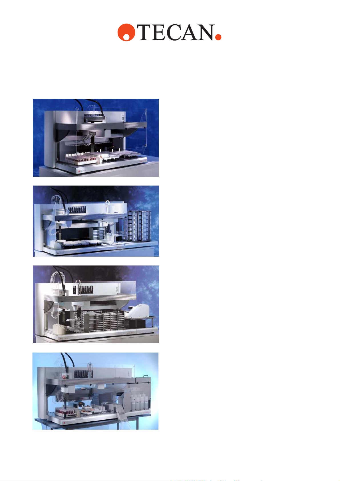
Genesis RSP Instrument
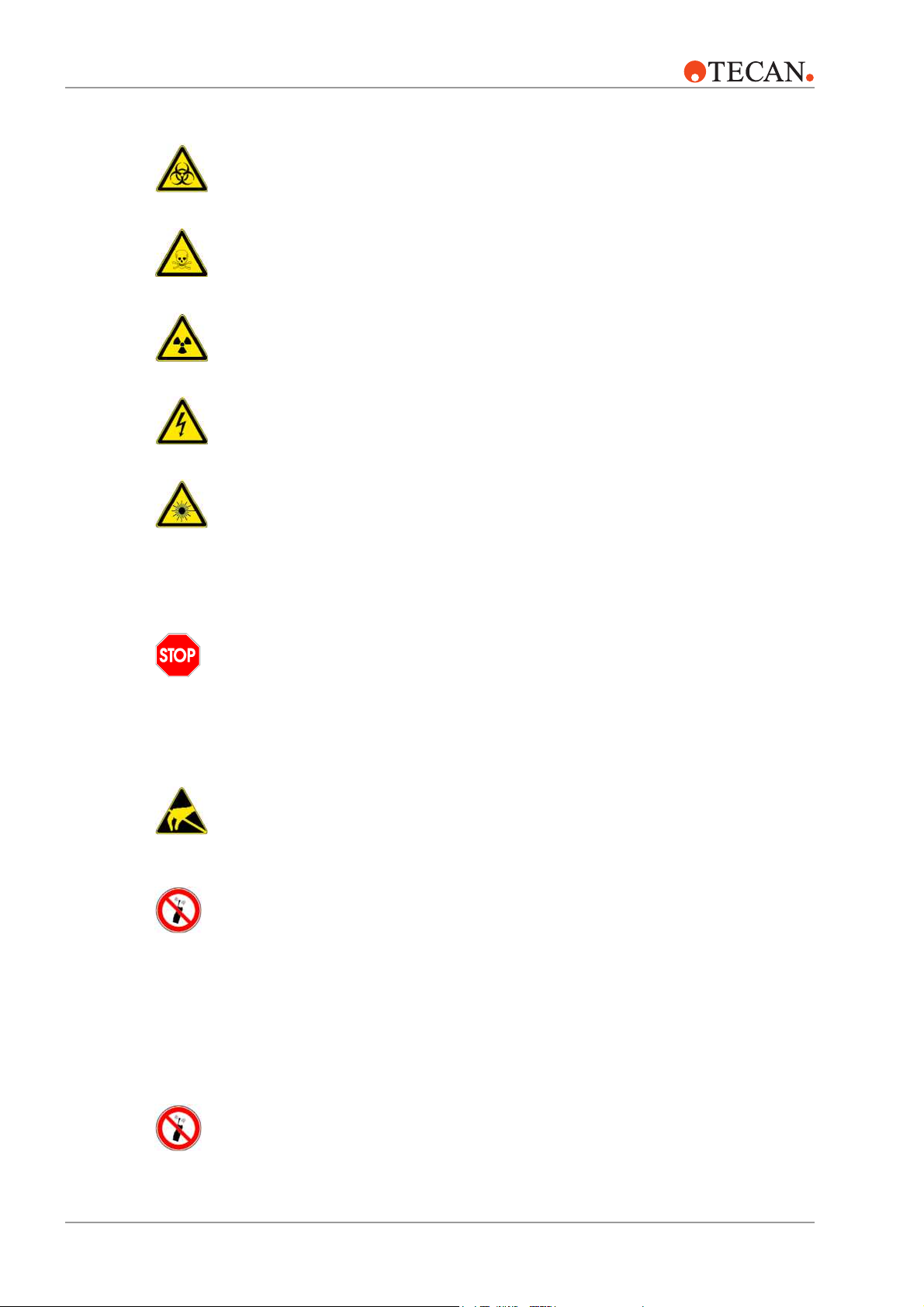
Genesis RWS Logistics Workstation
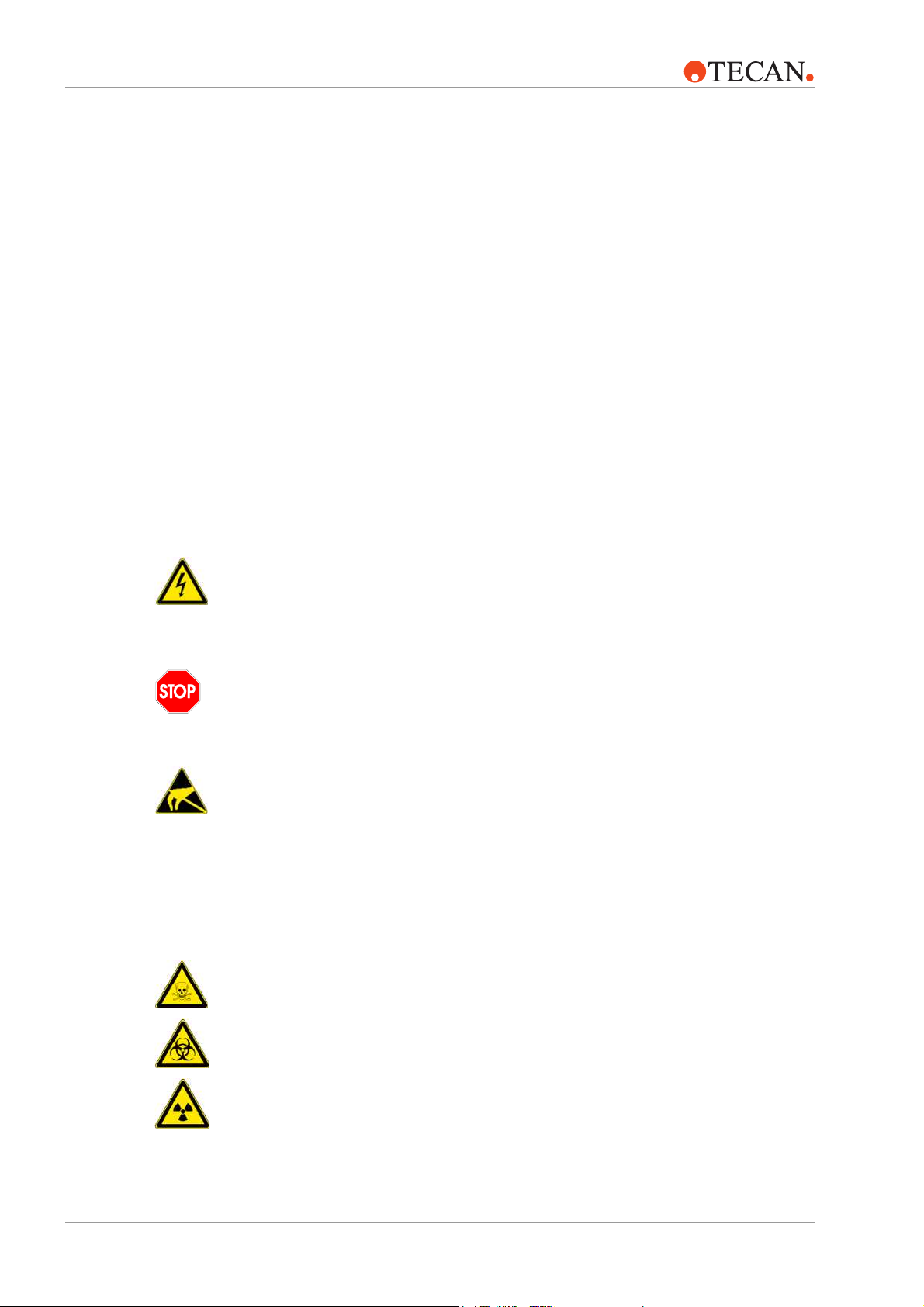
Genesis RWS Assay Workstation
Doc ID 391895 Version 1.0, August 2002
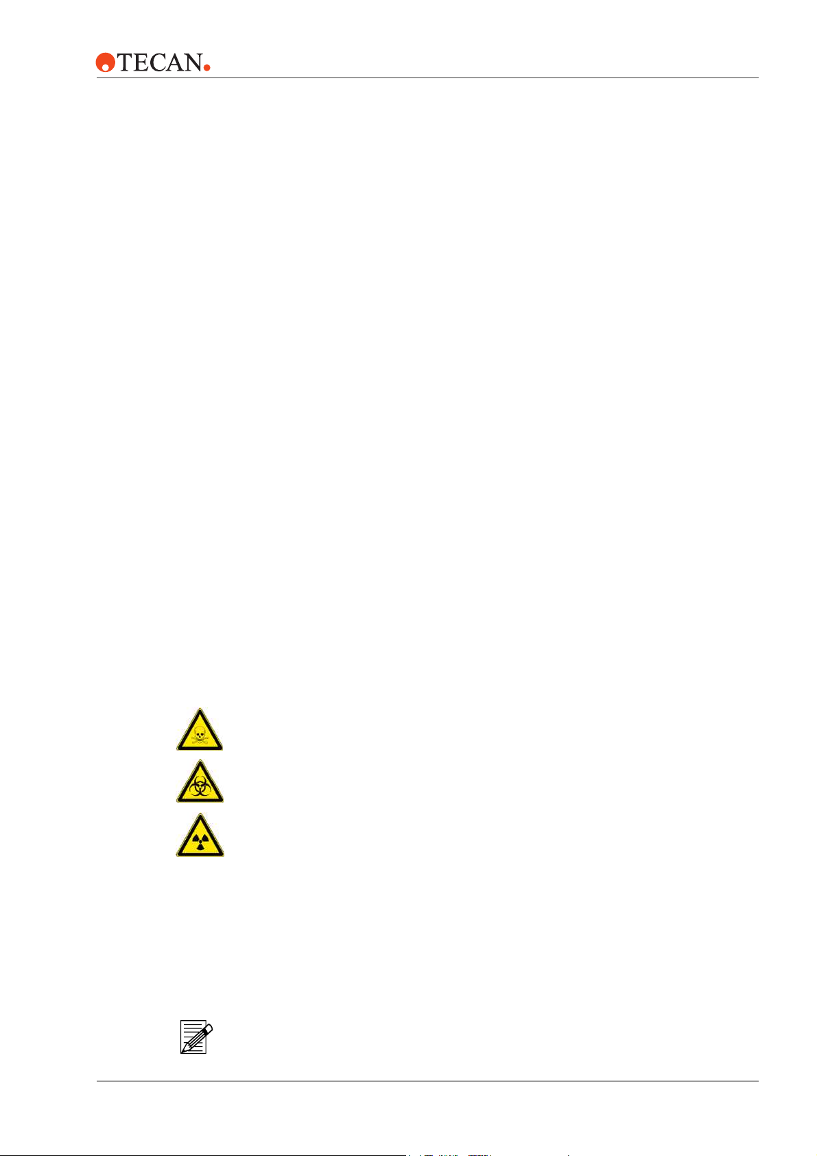
Genesis RMP Instrument
Page 2

Customer Support Tecan Schweiz AG and its representatives maintain a fully trained staff of technical
specialists around the world. For any technical question, contact your nearest Tecan
representative or:
TECAN Schweiz AG
Seestrasse 103
CH-8708 Männedorf
Expertline Telephone
Document History Doc ID Version Major changes Issue
391895 V1.0 first issue August 2002
The information contained in this document is subject to change without notice.
Telephone
Te le f ax
E-mail
Internet
Te le f ax
E-mail
+41 1 922 81 11
+41 1 922 81 12
info@tecan.com
www.tecan.com
+41 1 922 81 81
+41 1 922 84 84
expertline-eu@tecan.com
Copyright © 2002 TECAN Schweiz AG, Switzerland, all rights reserved
Page 3

Table of Contents
Table of Contents
1 About This Manual
2 Safety
2.1 User Qualification . . . . . . . . . . . . . . . . . . . . . . . . . . . . . . . . . . . . . . . 2 – 1
2.2 Notices and Symbols. . . . . . . . . . . . . . . . . . . . . . . . . . . . . . . . . . . . . 2 – 1
2.2.1 Warning Notices Used in This Manual . . . . . . . . . . . . . . . . 2 – 1
2.2.2 Warning Notices Attached to the Product or Its
Surroundings . . . . . . . . . . . . . . . . . . . . . . . . . . . . . . . . . . . . 2 – 2
2.3 Use of the Product. . . . . . . . . . . . . . . . . . . . . . . . . . . . . . . . . . . . . . . 2 – 3
2.4 Product Safety. . . . . . . . . . . . . . . . . . . . . . . . . . . . . . . . . . . . . . . . . . 2 – 4
2.4.1 Instrument-Related Hazards and Safety Measures. . . . . . . 2 – 4
2.4.2 Other Hazards and Safety Measures . . . . . . . . . . . . . . . . . 2 – 4
2.4.3 Safety Elements . . . . . . . . . . . . . . . . . . . . . . . . . . . . . . . . . 2 – 5
2.5 Decontamination . . . . . . . . . . . . . . . . . . . . . . . . . . . . . . . . . . . . . . . . 2 – 5
2.6 General Safety Rules . . . . . . . . . . . . . . . . . . . . . . . . . . . . . . . . . . . . 2 – 6
3 Product Description
3.1 Technical Data and Requirements . . . . . . . . . . . . . . . . . . . . . . . . . . 3 – 2
3.1.1 Dimensions and Weights. . . . . . . . . . . . . . . . . . . . . . . . . . . 3 – 2
3.1.2 Supply Ratings . . . . . . . . . . . . . . . . . . . . . . . . . . . . . . . . . . 3 – 6
3.1.3 Environmental Conditions . . . . . . . . . . . . . . . . . . . . . . . . . . 3 – 7
3.1.4 Computer and Software Requirements . . . . . . . . . . . . . . . . 3 – 8
3.1.5 Additional Data for System Modules . . . . . . . . . . . . . . . . . . 3 – 8
3.2 Compatibility Matrix . . . . . . . . . . . . . . . . . . . . . . . . . . . . . . . . . . . . . . 3 – 9
4 Transport and Installation
4.1 Site Inspection. . . . . . . . . . . . . . . . . . . . . . . . . . . . . . . . . . . . . . . . . . 4 – 1
4.2 Transport . . . . . . . . . . . . . . . . . . . . . . . . . . . . . . . . . . . . . . . . . . . . . . 4 – 2
4.3 Installation . . . . . . . . . . . . . . . . . . . . . . . . . . . . . . . . . . . . . . . . . . . . . 4 – 3
4.3.1 Unpacking and Positioning . . . . . . . . . . . . . . . . . . . . . . . . . 4 – 3
4.3.2 RMP Specific Installation Tasks . . . . . . . . . . . . . . . . . . . . . 4 – 3
4.3.3 RWS Specific Installation Tasks . . . . . . . . . . . . . . . . . . . . 4 – 13
4.3.4 Further Options and Modules for RSP/RWS . . . . . . . . . . . 4 – 14
4.3.5 Computer, Software. . . . . . . . . . . . . . . . . . . . . . . . . . . . . . 4 – 15
4.4 Commissioning . . . . . . . . . . . . . . . . . . . . . . . . . . . . . . . . . . . . . . . . 4 – 16
4.5 Conformity Assessment and CE Marking for RWS . . . . . . . . . . . . . 4 – 18
4.6 Site Acceptance . . . . . . . . . . . . . . . . . . . . . . . . . . . . . . . . . . . . . . . 4 – 18
August 2002 Genesis RSP, RWS and RMP Service Manual – Doc ID 391895 V1.0 iii
Page 4

Table of Contents
5 Maintenance
5.1 Concerning Your Safety . . . . . . . . . . . . . . . . . . . . . . . . . . . . . . . . . . 5 – 1
5.2 Consumables . . . . . . . . . . . . . . . . . . . . . . . . . . . . . . . . . . . . . . . . . . 5 – 1
5.3 Maintenance Schedule . . . . . . . . . . . . . . . . . . . . . . . . . . . . . . . . . . . 5 – 2
5.3.1 Daily/Weekly Maintenance . . . . . . . . . . . . . . . . . . . . . . . . . 5 – 2
5.3.2 Half-Yearly Maintenance . . . . . . . . . . . . . . . . . . . . . . . . . . 5 – 2
5.3.3 Yearly Maintenance . . . . . . . . . . . . . . . . . . . . . . . . . . . . . . 5 – 4
6 Replacement of Spare Parts, Repair
6.1 General Notes on Repair . . . . . . . . . . . . . . . . . . . . . . . . . . . . . . . . . 6 – 4
6.1.1 Concerning Your Safety . . . . . . . . . . . . . . . . . . . . . . . . . . . 6 – 4
6.1.2 General Repair Tasks. . . . . . . . . . . . . . . . . . . . . . . . . . . . . 6 – 5
6.1.3 Operating Tests after Repair . . . . . . . . . . . . . . . . . . . . . . . 6 – 6
6.2 Abstract of Important Data . . . . . . . . . . . . . . . . . . . . . . . . . . . . . . . . 6 – 7
6.2.1 Special Tools . . . . . . . . . . . . . . . . . . . . . . . . . . . . . . . . . . . 6 – 7
6.2.2 Jumper and Address Settings Overview. . . . . . . . . . . . . . . 6 – 8
6.2.3 CAN-Bus Resistance Test . . . . . . . . . . . . . . . . . . . . . . . . 6 – 10
6.2.4 Software Error Messages . . . . . . . . . . . . . . . . . . . . . . . . . 6 – 11
6.3 Instrument – Disassembly and Assembly Procedures . . . . . . . . . . 6 – 22
6.3.1 Worktable . . . . . . . . . . . . . . . . . . . . . . . . . . . . . . . . . . . . . 6 – 22
6.3.2 Door Locks . . . . . . . . . . . . . . . . . . . . . . . . . . . . . . . . . . . . 6 – 24
6.3.3 X-Drive Assembly . . . . . . . . . . . . . . . . . . . . . . . . . . . . . . . 6 – 25
6.3.4 Power Modules . . . . . . . . . . . . . . . . . . . . . . . . . . . . . . . . . 6 – 34
6.3.5 Electronic Boards . . . . . . . . . . . . . . . . . . . . . . . . . . . . . . . 6 – 37
6.4 Liquid System – Disassembly and Assembly Procedures . . . . . . . 6 – 46
6.4.1 Overview. . . . . . . . . . . . . . . . . . . . . . . . . . . . . . . . . . . . . . 6 – 46
6.4.2 Tubing System . . . . . . . . . . . . . . . . . . . . . . . . . . . . . . . . . 6 – 47
6.4.3 Diluter and Dilback . . . . . . . . . . . . . . . . . . . . . . . . . . . . . . 6 – 50
6.4.4 MPO/FWO . . . . . . . . . . . . . . . . . . . . . . . . . . . . . . . . . . . . 6 – 54
6.4.5 Low Volume Option . . . . . . . . . . . . . . . . . . . . . . . . . . . . . 6 – 62
6.4.6 6-Way Valve Option . . . . . . . . . . . . . . . . . . . . . . . . . . . . . 6 – 69
6.5 LiHa 1 – Disassembly and Assembly Procedures . . . . . . . . . . . . . 6 – 73
6.5.1 Overview. . . . . . . . . . . . . . . . . . . . . . . . . . . . . . . . . . . . . . 6 – 73
6.5.2 Complete LiHa 1 Assembly . . . . . . . . . . . . . . . . . . . . . . . 6 – 75
6.5.3 X-Flex Cable . . . . . . . . . . . . . . . . . . . . . . . . . . . . . . . . . . . 6 – 76
6.5.4 ILID Cable. . . . . . . . . . . . . . . . . . . . . . . . . . . . . . . . . . . . . 6 – 76
6.5.5 ILID Flat Cable . . . . . . . . . . . . . . . . . . . . . . . . . . . . . . . . . 6 – 76
6.5.6 Electronic Boards for LiHa 1 . . . . . . . . . . . . . . . . . . . . . . . 6 – 78
6.5.7 Y-Belt and Y-Spreading Belt. . . . . . . . . . . . . . . . . . . . . . . 6 – 79
6.5.8 Y-Motor and Y-Spreading Motor. . . . . . . . . . . . . . . . . . . . 6 – 80
6.5.9 Tip Adapter . . . . . . . . . . . . . . . . . . . . . . . . . . . . . . . . . . . . 6 – 81
6.5.10 Ensure Operating Readiness . . . . . . . . . . . . . . . . . . . . . . 6 – 81
iv Genesis RSP, RWS and RMP Service Manual – Doc ID 391895 V1.0 August 2002
Page 5

Table of Contents
6.6 LiHa 2 – Disassembly and Assembly Procedures. . . . . . . . . . . . . . 6 – 83
6.6.1 Overview . . . . . . . . . . . . . . . . . . . . . . . . . . . . . . . . . . . . . . 6 – 83
6.6.2 Complete LiHa 2 Assembly . . . . . . . . . . . . . . . . . . . . . . . . 6 – 85
6.6.3 X-Flex Cable . . . . . . . . . . . . . . . . . . . . . . . . . . . . . . . . . . . 6 – 88
6.6.4 ILID Cable . . . . . . . . . . . . . . . . . . . . . . . . . . . . . . . . . . . . . 6 – 89
6.6.5 ILID Flat Cable. . . . . . . . . . . . . . . . . . . . . . . . . . . . . . . . . . 6 – 90
6.6.6 Electronic Boards for LiHa 2 . . . . . . . . . . . . . . . . . . . . . . . 6 – 91
6.6.7 Y-Belt and Y-Spreading Belt . . . . . . . . . . . . . . . . . . . . . . . 6 – 95
6.6.8 Y-Motor and Y-Spreading Motor . . . . . . . . . . . . . . . . . . . . 6 – 97
6.6.9 Tip Adapter . . . . . . . . . . . . . . . . . . . . . . . . . . . . . . . . . . . . 6 – 98
6.6.10 Lower DiTi Eject Option. . . . . . . . . . . . . . . . . . . . . . . . . . . 6 – 99
6.6.11 Ensure Operating Readiness . . . . . . . . . . . . . . . . . . . . . 6 – 104
6.7 RoMa 1 – Disassembly and Assembly Procedures . . . . . . . . . . . 6 – 106
6.7.1 Overview . . . . . . . . . . . . . . . . . . . . . . . . . . . . . . . . . . . . . 6 – 106
6.7.2 Complete RoMa 1 Assembly . . . . . . . . . . . . . . . . . . . . . . 6 – 109
6.7.3 Gripper Fingers . . . . . . . . . . . . . . . . . . . . . . . . . . . . . . . . 6 – 109
6.7.4 Gripper Module Head, Gripper Board . . . . . . . . . . . . . . . 6 – 109
6.7.5 Rotator Motor. . . . . . . . . . . . . . . . . . . . . . . . . . . . . . . . . . 6 – 110
6.7.6 X-Flex Cable . . . . . . . . . . . . . . . . . . . . . . . . . . . . . . . . . . 6 – 110
6.7.7 Gripper/Rotator Flex Cables . . . . . . . . . . . . . . . . . . . . . . 6 – 110
6.7.8 Y/R- and Z/G-DC-Servo Board . . . . . . . . . . . . . . . . . . . . 6 – 110
6.7.9 RoMa 1 Backplane . . . . . . . . . . . . . . . . . . . . . . . . . . . . . 6 – 111
6.7.10 Y-Belt. . . . . . . . . . . . . . . . . . . . . . . . . . . . . . . . . . . . . . . . 6 – 111
6.7.11 Y- and Z-Motor . . . . . . . . . . . . . . . . . . . . . . . . . . . . . . . . 6 – 111
6.7.12 Z-Brake . . . . . . . . . . . . . . . . . . . . . . . . . . . . . . . . . . . . . . 6 – 112
6.7.13 Ensuring Operating Readiness . . . . . . . . . . . . . . . . . . . . 6 – 113
6.8 RoMa 2 – Disassembly and Assembly Procedures . . . . . . . . . . . 6 – 114
6.8.1 Overview . . . . . . . . . . . . . . . . . . . . . . . . . . . . . . . . . . . . . 6 – 114
6.8.2 Complete RoMa 2 Assembly . . . . . . . . . . . . . . . . . . . . . . 6 – 117
6.8.3 Mechanical Adjustment After Reinstallation . . . . . . . . . . 6 – 118
6.8.4 Gripper Fingers . . . . . . . . . . . . . . . . . . . . . . . . . . . . . . . . 6 – 121
6.8.5 Gripper Module Head, Gripper Board . . . . . . . . . . . . . . . 6 – 122
6.8.6 Rotator Motor. . . . . . . . . . . . . . . . . . . . . . . . . . . . . . . . . . 6 – 125
6.8.7 X-Flex Cable . . . . . . . . . . . . . . . . . . . . . . . . . . . . . . . . . . 6 – 126
6.8.8 Gripper/Rotator Flex Cables . . . . . . . . . . . . . . . . . . . . . . 6 – 129
6.8.9 Y/R- and Z/G-DC-Servo Board . . . . . . . . . . . . . . . . . . . . 6 – 131
6.8.10 RoMa 2 Backplane . . . . . . . . . . . . . . . . . . . . . . . . . . . . . 6 – 132
6.8.11 Y-Belt. . . . . . . . . . . . . . . . . . . . . . . . . . . . . . . . . . . . . . . . 6 – 133
6.8.12 Y-Motor . . . . . . . . . . . . . . . . . . . . . . . . . . . . . . . . . . . . . . 6 – 135
6.8.13 Z-Motor . . . . . . . . . . . . . . . . . . . . . . . . . . . . . . . . . . . . . . 6 – 136
6.8.14 Z-Brake . . . . . . . . . . . . . . . . . . . . . . . . . . . . . . . . . . . . . . 6 – 137
6.8.15 Ensuring Operating Readiness . . . . . . . . . . . . . . . . . . . . 6 – 138
August 2002 Genesis RSP, RWS and RMP Service Manual – Doc ID 391895 V1.0 v
Page 6

Table of Contents
6.9 PosID 1 – Disassembly and Assembly Procedures . . . . . . . . . . . 6 – 139
6.9.1 Complete PosID 1 Assembly . . . . . . . . . . . . . . . . . . . . . 6 – 139
6.9.2 X-Drive Assembly (X-Belt, X-Motor, X-Flex Cable) . . . . 6 – 140
6.9.3 Electronic Boards for PosID 1. . . . . . . . . . . . . . . . . . . . . 6 – 141
6.9.4 Scanner Assembly (Scanner Head, B-Motor). . . . . . . . . 6 – 144
6.9.5 Y-Belt Assembly (Y-Belt, Y-Motor) . . . . . . . . . . . . . . . . . 6 – 146
6.9.6 No Tube Sensor . . . . . . . . . . . . . . . . . . . . . . . . . . . . . . . 6 – 147
6.9.7 Ensure Operating Readiness . . . . . . . . . . . . . . . . . . . . . 6 – 148
6.10 PosID 2 – Disassembly and Assembly Procedures . . . . . . . . . . . 6 – 149
6.10.1 Complete PosID 2 Assembly . . . . . . . . . . . . . . . . . . . . . 6 – 150
6.10.2 X-Drive Assembly (X-Belt, X-Motor, X-Flex Cable) . . . . 6 – 153
6.10.3 Electronic Boards for PosID 2. . . . . . . . . . . . . . . . . . . . . 6 – 155
6.10.4 Scanner Assembly (B-Motor, Scanner Head and Cable) 6 – 157
6.10.5 Y-Drive Assembly (Y-Belt, Gripper Assembly, Y-Motor). 6 – 159
6.10.6 No Tube Sensor . . . . . . . . . . . . . . . . . . . . . . . . . . . . . . . 6 – 161
6.10.7 Ensure Operating Readiness . . . . . . . . . . . . . . . . . . . . . 6 – 162
7 Check Lists Spare Parts
7.1 Spare Parts Instrument. . . . . . . . . . . . . . . . . . . . . . . . . . . . . . . . . . . 7 – 2
7.1.1 Spare Parts Worktable . . . . . . . . . . . . . . . . . . . . . . . . . . . . 7 – 2
7.1.2 Spare Parts Door Locks . . . . . . . . . . . . . . . . . . . . . . . . . . . 7 – 3
7.1.3 Spare Parts X-Drive Assembly . . . . . . . . . . . . . . . . . . . . . . 7 – 4
7.1.4 Spare Parts Power Modules . . . . . . . . . . . . . . . . . . . . . . . . 7 – 5
7.1.5 Spare Parts Electronic Boards . . . . . . . . . . . . . . . . . . . . . . 7 – 7
7.2 Spare Parts Liquid System . . . . . . . . . . . . . . . . . . . . . . . . . . . . . . . 7 – 10
7.2.1 Spare Parts Tubing Systems . . . . . . . . . . . . . . . . . . . . . . 7 – 10
7.2.2 Spare Parts Diluter/Dilback. . . . . . . . . . . . . . . . . . . . . . . . 7 – 12
7.2.3 Spare Parts MPO/FWO . . . . . . . . . . . . . . . . . . . . . . . . . . 7 – 14
7.2.4 Spare Parts Low Volume Option . . . . . . . . . . . . . . . . . . . 7 – 16
7.2.5 Spare Parts 6-Way Valve Option . . . . . . . . . . . . . . . . . . . 7 – 18
7.3 Spare Parts LiHa 1 . . . . . . . . . . . . . . . . . . . . . . . . . . . . . . . . . . . . . 7 – 20
7.4 Spare Parts LiHa 2 . . . . . . . . . . . . . . . . . . . . . . . . . . . . . . . . . . . . . 7 – 22
7.5 Spare Parts RoMa 1 . . . . . . . . . . . . . . . . . . . . . . . . . . . . . . . . . . . . 7 – 25
7.6 Spare Parts RoMa 2 . . . . . . . . . . . . . . . . . . . . . . . . . . . . . . . . . . . . 7 – 27
7.7 Spare Parts PosID 1. . . . . . . . . . . . . . . . . . . . . . . . . . . . . . . . . . . . 7 – 29
7.8 Spare Parts PosID 2. . . . . . . . . . . . . . . . . . . . . . . . . . . . . . . . . . . . 7 – 31
8 Instruments at a Glance
8.1 Genesis RSP . . . . . . . . . . . . . . . . . . . . . . . . . . . . . . . . . . . . . . . . . . 8 – 2
8.2 Genesis RMP . . . . . . . . . . . . . . . . . . . . . . . . . . . . . . . . . . . . . . . . . . 8 – 3
8.3 Genesis RWS Logistics . . . . . . . . . . . . . . . . . . . . . . . . . . . . . . . . . . 8 – 4
8.4 Genesis RWS Assay . . . . . . . . . . . . . . . . . . . . . . . . . . . . . . . . . . . . 8 – 5
vi Genesis RSP, RWS and RMP Service Manual – Doc ID 391895 V1.0 August 2002
Page 7

Table of Contents
9Diagrams
9.1 Genesis RSP, RMP and RWS . . . . . . . . . . . . . . . . . . . . . . . . . . . . . 9 – 1
9.2 Instrument . . . . . . . . . . . . . . . . . . . . . . . . . . . . . . . . . . . . . . . . . . . . . 9 – 5
9.2.1 Power Modules . . . . . . . . . . . . . . . . . . . . . . . . . . . . . . . . . . 9 – 5
9.2.2 Electronic Boards . . . . . . . . . . . . . . . . . . . . . . . . . . . . . . . 9 – 12
9.3 Liquid System . . . . . . . . . . . . . . . . . . . . . . . . . . . . . . . . . . . . . . . . . 9 – 40
9.3.1 MPO/FWO . . . . . . . . . . . . . . . . . . . . . . . . . . . . . . . . . . . . . 9 – 40
9.3.2 Diluter/Dilback . . . . . . . . . . . . . . . . . . . . . . . . . . . . . . . . . . 9 – 44
9.3.3 Low Volume Option . . . . . . . . . . . . . . . . . . . . . . . . . . . . . . 9 – 48
9.4 LiHa 1 and LiHa 2 . . . . . . . . . . . . . . . . . . . . . . . . . . . . . . . . . . . . . . 9 – 51
9.5 RoMa 1 and RoMa 2 . . . . . . . . . . . . . . . . . . . . . . . . . . . . . . . . . . . . 9 – 56
9.6 PosID 1 and PosID 2. . . . . . . . . . . . . . . . . . . . . . . . . . . . . . . . . . . . 9 – 64
August 2002 Genesis RSP, RWS and RMP Service Manual – Doc ID 391895 V1.0 vii
Page 8

Table of Contents
viii Genesis RSP, RWS and RMP Service Manual – Doc ID 391895 V1.0 August 2002
Page 9

1 About This Manual
1 – About This Manual
Purpose of This
Chapter
Introduction The structure and contents of this manual were compiled based on the results of a
Applicability The instructions given in this document are applicable for Genesis Instruments type …
Purpose of This
Document
This chapter points out the purpose of the manual, specifies the instruments the manual
deals with and for whom the manual is intended. Furthermore, it contains a list with
relevant reference documents, explains the symbols, conventions and abbreviations
used and offers general information.
worldwide survey between Tecan field service engineers. We hope the manual fits your
requirements and would be happy to get any feedback. Just contact the documentation
service group of Tecan Schweiz AG.
• Genesis RSP
• Genesis RWS Logistics
• Genesis RWS Assay
• Genesis RMP
This document serves as a reference guide for Tecan trained and authorized personnel
only. It provides all relevant information for installation and servicing of the instrument –
with exception of information covered by the respective reference documents (see
section ‘Reference Documents’ later in this chapter).
Target Groups This manual addresses the following target groups:
Target group Description Tasks/responsibilities
Field service
engineer
System integrator A legal person (e.g. a RO within
August 2002 Genesis RSP, RWS and RMP Service Manual – Doc ID 391895 V1.0 1 – 1
Experienced field service
engineer who has visited a Tecan
service training and has been
authorized for servicing the
Genesis RSP, RMP and RWS
instruments.
Tecan group or a distributor) who
acts in a legal sense between
Tecan Schweiz AG
(manufacturer of sub-assembly)
and end-user.
• Site inspection
• Installation
• Commissioning
• Site acceptance
• Maintenance
• Repair
• Calibration
• Conformity assessment
and CE marking (see
Section 4.5).
Page 10

1 – About This Manual
Reference
Documents
The following documents are helpful for installation and servicing of the instrument.
They are not enclosed with this manual, nevertheless they are part of the service
documentation.
Document type Valid for …/document title Doc ID
Operating Manual Genesis RSP and NPS
Genesis RMP
Genesis RWS
Carousel
Columbus Washer
Sunrise Reader
Spectra & Rainbow Readers
Instrument
Software Manual
Installation Manual Lower DiTi eject option 2
Genesis Instrument Doc ID 390 791
Low volume option 1: tube fastening
Access option/Signal lamp (RSP, RWS)
Doc ID 390 783
I 119 100
Doc ID 391 197
Doc ID 391 209
I109004
I137301
I139003
Doc ID 391 276
Doc ID 391 228
Doc ID 392 330
Door lock V2 (RMP)
Alarm device V2 (RMP)
Form or Checklist Decontamination Declaration
Genesis Maintenance and Service
Logbook, including:
• Installation Qualification
• Operation Qualification
• Acceptance Protocol
• Daily/Weekly Maintenance Checklist
• Preventive Maintenance Checklist
• Service Checklist
Furthermore, you may find following Application Software Manuals useful:
Area of application Application software Doc ID
Diagnostics TOPS
Doc ID 391 260
Doc ID 391 255
Doc ID 390 901
Doc ID 390 924
Doc ID 391 180
Doc ID 391 182
Doc ID 391 825
Doc ID 391 193
Doc ID 391 181
Doc ID 391 183
I 117 578
Logic
Life Science FACTS
Gemini
1 – 2 Genesis RSP, RWS and RMP Service Manual – Doc ID 391895 V1.0 August 2002
Doc ID 391 110
Doc ID 391 252
Doc ID 391 201
Page 11

1 – About This Manual
Symbols Used in
This Manual
Instrument
Overviews
Safety Symbols
The safety symbols are explained in Chapter 2, ‘Safety’.
Useful Notes
Useful notes appear as follows:
Note
Gives helpful information about the equipment or regarding proceedings, tentative
clarifications etc.
In Chapter 8, ‘Instruments at a Glance’ you will find useful illustrations of the
instruments giving an overview of the main components.
On the detail drawings and the text passages in this document (mainly in Chapter 6,
‘Replacement of Spare Parts, Repair’), one main part is always designated with the
identical item number – for example (8) for LiHa – as on the relevant illustration in
chapter 8. Item numbers of their components consist always of the main part item
number, a dash and the item number of the component – for example (8-04) for LiHa
backplane.
Abbreviations and
Acronyms Used in
This Manual
FaWa Fast wash pump
FSE Field service engineer
FWO Fast wash option
ILID Integrated liquid detection
LICOS Liquid container supervisor
LiHa Liquid handling arm
MP Micro plate
MPO Monitored pump option
PCB Printed circuit board
PosID Positive identification option, barcode reader
RMP Robotic microplate processor
RoMa Robotic manipulator arm
RSP Robotic sample processor
RWS Robotic workstation
August 2002 Genesis RSP, RWS and RMP Service Manual – Doc ID 391895 V1.0 1 – 3
Page 12

1 – About This Manual
1 – 4 Genesis RSP, RWS and RMP Service Manual – Doc ID 391895 V1.0 August 2002
Page 13

2 Safety
2 – Safety
Purpose of This
Chapter
Significance of
These Safety
Instructions
This chapter contains specific rules of behavior and warnings from hazards with regard
to installation, setup, maintenance and repair of the Genesis RSP, RMP or RWS
instruments.
The safety of users and personnel can only be ensured if these safety instructions and
the safety-related warnings in the individual chapters are strictly observed and followed.
Therefore, the Service Manual must always be available to all persons performing the
tasks described herein.
In addition to the safety instructions given in this Service Manual, the safety instructions
pointed out in the Operating Manuals of the Genesis RSP, RMP or RWS instruments
apply as well.
2.1 User Qualification
FSE Authorization The field service engineers (FSE) are specially trained personnel. Exclusively FSEs are
entitled to perform the maintenance and service work described in this Service Manual.
The manufacturer Tecan authorizes the FSEs if they fulfill the following particular
qualifications:
WARNING
Symbols
• They must have received appropriate service and operator training from Tecan.
• They must be familiar with the good laboratory practice guidelines.
• They must have read and understood the instructions in this Service Manual.
2.2 Notices and Symbols
2.2.1 Warning Notices Used in This Manual
The symbols used for safety-related notices have the following significance:
WARNING
Generally, the triangular warning symbol indicates the possibility of personal injury or
even loss of life if the instructions are not followed.
Whenever possible, the symbol indicates the hazard a person is exposed to more
specifically. The symbols used in this Service Manual have the following significance:
August 2002 Genesis RSP, RWS and RMP Service Manual – Doc ID 391895 V1.0 2 – 1
Page 14
2 – Safety
WARNING
Biological hazard
WARNING
Chemical hazard
WARNING
Radioactive radiation
WARNING
Electrical danger
WARNING
Laser radiation
ATTENTION
Symbols
ATTENTIONS appear as follows:
ATTENTION
With the general “STOP” symbol, ATTENTIONs indicate the possibility of equipment
damage, malfunctions or incorrect process results, if instructions are not followed.
Other symbols indicate the significance of the ATTENTION more specifically.
ATTENTION
Damage to electronics by electrostatic discharge.
Always follow ESD safety practices.
ATTENTION
Disturbance of functions by electromagnetic RF waves.
Do not use a cellular phone.
2.2.2 Warning Notices Attached to the Product or Its Surroundings
Cellular Phones
Prohibited
Do not use cellular phones in the proximity of the instrument.
This symbol is attached to the safety panel of the instrument. The symbol must also be
attached to the laboratory door.
Damaged or fallen off symbols (notices or stickers) must be replaced immediately.
2 – 2 Genesis RSP, RWS and RMP Service Manual – Doc ID 391895 V1.0 August 2002
Page 15

2 – Safety
2.3 Use of the Product
Intended Use The Genesis RSP, RMP or RWS instruments are to be applied and used exclusively in
the following application fields. Any other use is considered improper and is strictly
forbidden.
• The Genesis RSP is intended for liquid pipetting for generally known laboratory
methods according to common safety precautions.
• The Genesis RMP is intended for fully automated processing of 96-well microplate
based ELISA (Enzyme Linked Immuno Sorbent Assay) and ELISA-like tests,
starting from sample pipetting and ending with result reading.
All ELISA test procedures have to be validated prior to performing routine tests.
• The Genesis RWS Logistics is intended for pipetting tasks as well as storage,
identification and transfer of microplates. It is to be applied for research only.
The Genesis RWS Logistics is intended to be part of a liquid handling system and
as such installed and put into operation by a trained Tecan or Tecan authorized
system integrator.
• The Genesis RWS Assay is intended for processing of microplate based tests,
including liquid handling, incubation, wash, read and data acquisition. It is to be
applied for research only.
The Genesis RWS Assay is intended to be part of a liquid handling system and as
such installed and put into operation by a trained Tecan or Tecan authorized system
integrator.
All Genesis instruments are intended for indoor operation and storage only.
Improper Use Due to their open architecture, the Genesis RWS Assay and Logistics are not intended
for clinical and diagnostic applications. These applications would be carried out by less
qualified people, exposing them to dangerous liquids in case of instrument malfunction.
Incorrect use of the Genesis RMP may lead to false test results and may cause
exposure of the operator to potentially dangerous compounds.
Do not attempt to use liquids with undissolved particles as this could result in liquid not
being dispensed due to clogged tips.
August 2002 Genesis RSP, RWS and RMP Service Manual – Doc ID 391895 V1.0 2 – 3
Page 16
2 – Safety
2.4 Product Safety
Principle The Genesis RSP, RMP or RWS instruments are designed and built in accordance with
the present state-of-the-art technology and the recognized technical safety regulations.
Nevertheless, risks to users, property, and the environment can arise when the
instrument is used carelessly or improperly.
The manufacturer has determined all residual dangers emanating from the instrument
in all life phases and from the process.
Appropriate warnings in the Operating Manuals of the Genesis RSP, RMP or RWS
instruments and in this Service Manual serve to make the user alert to these residual
dangers.
2.4.1 Instrument-Related Hazards and Safety Measures
Pay attention to the following safety notices:
WARNING
Electrical shock hazard.
Switch the instrument off and disconnect from mains whenever no power is required to
perform service tasks.
ATTENTION
Crimping of the tubing between top cover and case possible.
Secure the top cover from falling down during inspection work.
ATTENTION
Damage to the electronic boards due to electrostatic discharge (ESD).
Always wear a wrist strap when handling the boards.
2.4.2 Other Hazards and Safety Measures
WARNING
• Chemical, biological and radioactive hazards can be associated with the
substances used or the samples processed with the Genesis RSP, RMP or RWS
instrument.
• The same applies to waste disposal.
Always be aware of possible hazards associated with these substances.
Request a filled out and signed Decontamination Declaration prior to performing any
maintenance or repair tasks.
2 – 4 Genesis RSP, RWS and RMP Service Manual – Doc ID 391895 V1.0 August 2002
Page 17
2.4.3 Safety Elements
2 – Safety
Removal of
Protective
Devices
When to
Decontaminate
The protective and safety devices installed on the Genesis RSP, RMP or RWS
instrument must be neither removed nor disabled during operation.
If such elements were removed, e.g. for maintenance work, operation may only be
resumed when all protective and safety devices have been completely installed and
checked.
2.5 Decontamination
Apart from regular decontamination, the user must thoroughly decontaminate the
instrument according to standard laboratory regulations in the following cases:
• Before any maintenance or service work is performed on the instrument
• Before a Tecan field service engineer (FSE) performs any in-site work on the
instrument
• Before the instrument is returned to Tecan (e.g. for repair)
• Prior to storage of the instrument
• Prior to disposal of the instrument or parts of it
• Generally before the instrument or parts of it leave the user’s site.
Decontamination
Method
Decontamination
Declaration
The decontamination method must be adapted to the respective application and the
substances associated with it. The user takes the full responsibility for the appropriate
decontamination of the entire equipment.
WARNING
Biological or chemical hazard and/or radioactive radiation.
• Contamination hazard due to parts of the instrument which are not completely
decontaminated.
• Mind that not only the parts having direct contact with chemicals or biological
material must be treated, but also the tubing system as well as the whole upstream
equipment.
Before a Tecan FSE carries out any work on the instrument, or before the instrument is
returned to Tecan, the owner of the instrument must confirm in writing that the
decontamination has been performed properly and in accordance with good laboratory
practice guidelines. For this, the owner must enclose a Decontamination Declaration
form (Doc ID 390 901), which can be provided by Tecan.
Note: Tecan will refuse any instrument or a part of it, if the decontamination form is not
filled in and duly signed.
August 2002 Genesis RSP, RWS and RMP Service Manual – Doc ID 391895 V1.0 2 – 5
Page 18

2 – Safety
2.6 General Safety Rules
Legal Regulations Legal regulations, such as local, state and federal laws which prescribe the use or
application as well as the handling of dangerous materials in connection with the
Genesis RSP, RMP or RWS instrument must be strictly followed.
Duty of
Maintenance and
Care
Appropriate
Behavior
Spare Parts to Be
Used
Modifications Modifications to the Genesis RSP, RMP or RWS instrument are only permitted with the
The user is responsible for ensuring that the Genesis RSP, RMP or RWS instrument is
operated in proper condition only, and that maintenance, service, and repair jobs are
performed with care and on schedule.
Use exclusively tools suitable for the respective work sequence. Ensure that the tools
are in sound condition.
Handling and disposing of waste has to be in accordance with all local, state and federal
environmental, health, and safety laws and regulations.
Use only genuine spare parts for maintenance and repair.
written approval of the manufacturer. Modifications and upgrades shall only be carried
out by an authorized field service engineer. The manufacturer will decline any claim
resulting from unauthorized modifications.
2 – 6 Genesis RSP, RWS and RMP Service Manual – Doc ID 391895 V1.0 August 2002
Page 19
3 Product Description
3 – Product Description
Purpose of This
Chapter
Chapter Overview This chapter consists of the following sections:
This chapter summarizes the technical data of the Genesis instruments and contains an
overview of requirements, hardware, software and firmware compatibilities.
Note
For detailed information concerning optional modules as reader, washer, carousel etc.,
refer to their respective manuals.
Section Title Page
3.1 Technical Data and Requirements 3 – 2
3.1.1 Dimensions and Weights 3 – 2
3.1.2 Supply Ratings 3 – 6
3.1.3 Environmental Conditions 3 – 7
3.1.4 Computer and Software Requirements 3 – 8
3.1.5 Additional Data for System Modules 3 – 8
3.2 Compatibility Matrix 3 – 9
August 2002 Genesis RSP, RWS and RMP Service Manual – Doc ID 391895 V1.0 3 – 1
Page 20
3 – Product Description
3.1 Technical Data and Requirements
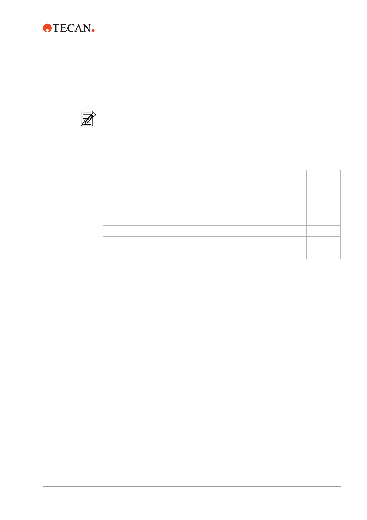
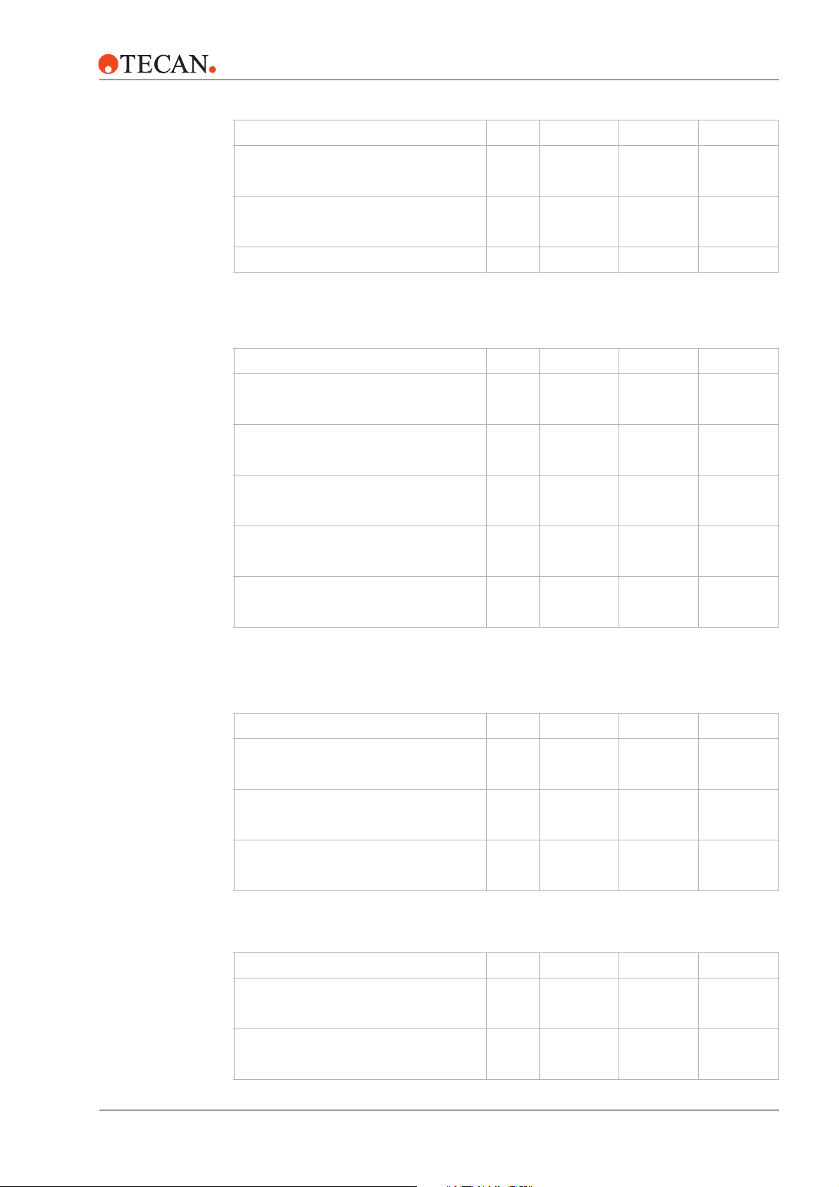
3.1.1 Dimensions and Weights
RSP Instrument
Dimensions
830 mm
(32.7")
Genesis RSP 100: 1051 mm (41.4")
Genesis RSP 150: 1426 mm (56.1")
Genesis RSP 200: 2026 mm (79.8")
1200 mm
(47.25")
1000 mm
(39.4")
RMP Instrument
Dimensions
front view
Genesis RSP 100: 1501 mm (59.1")
Genesis RSP 150: 1876 mm (73.9")
Genesis RSP 200: 2476 mm (97.5")
top view
RMP 100: 1405 mm (55.3")
RMP 150: 1780 mm (70.1")
RMP 200: 2380 mm (93.7")
805 mm (31.7")
780 mm (30.7")
1230 mm (48.4")
left side view
840 mm
(33.1")
1000 mm (39.4")
870 mm (30.7")
1230 mm (48.4")
RMP 100: 1856 mm (73.1")
RMP 150: 2230 mm (87.8")
RMP 200: 2830 mm (111.45")
840 mm (33.1")
3 – 2 Genesis RSP, RWS and RMP Service Manual – Doc ID 391895 V1.0 August 2002
Page 21
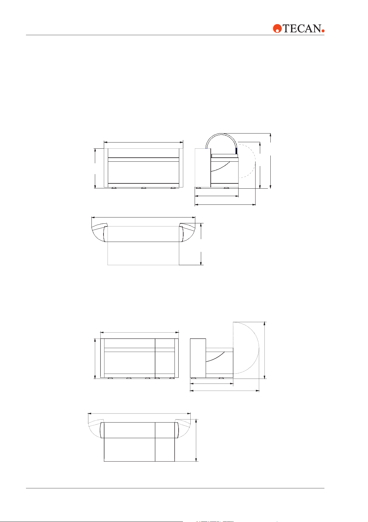
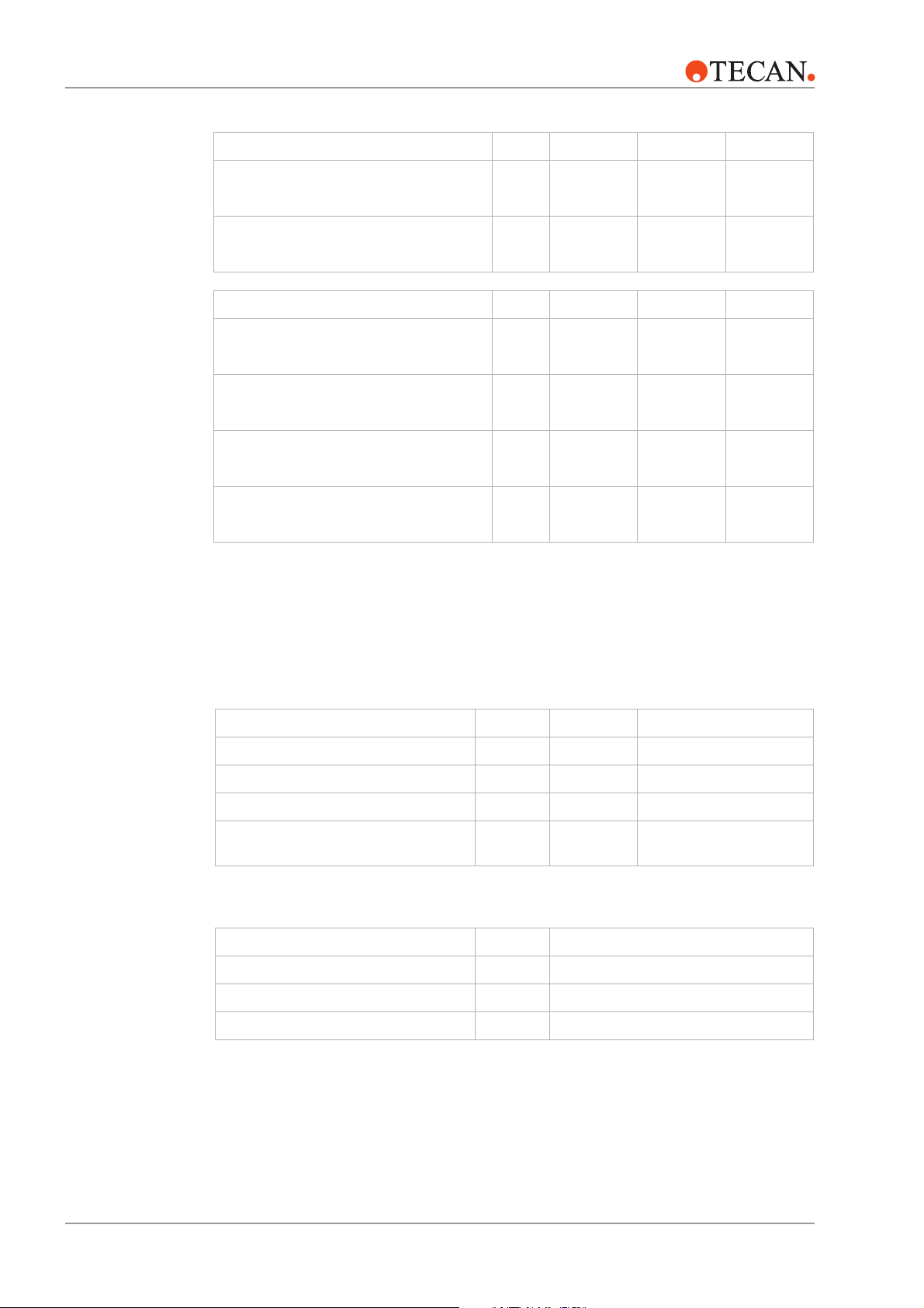
RWS Logistics
Workstation
Dimensions
830 mm
(32.7")
Logistics WS 100: 1051 mm (41.4")
Logistics WS 150: 1426 mm (56.1")
Logistics WS 200: 2026 mm (79.8")
3 – Product Description
1200 mm
(47.25")
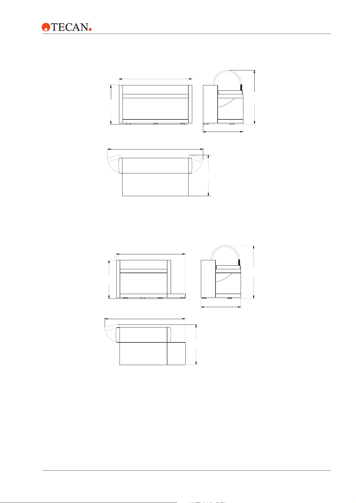
RWS Assay
Workstation
Dimensions
830 mm
(32.7")
Front View
Logistics WS 100: 1501 mm (59.1")
Logistics WS 150: 1876 mm (73.9")
Logistics WS 200: 2476 mm (97.5")
Top View
Assay WS 150: 1796 mm (70.7")
Assay WS 200: 2396 mm (94.4")
780 mm (30.7")
840 mm
(33.1")
Left Side View
1200 mm
(47.25")
Front View
Assay WS 150: 1970 mm (77.6")
Assay WS 200: 2570 mm (101.2")
Top View
840 mm
(33.1")
780 mm (30.7")
Left Side View
August 2002 Genesis RSP, RWS and RMP Service Manual – Doc ID 391895 V1.0 3 – 3
Page 22
3 – Product Description
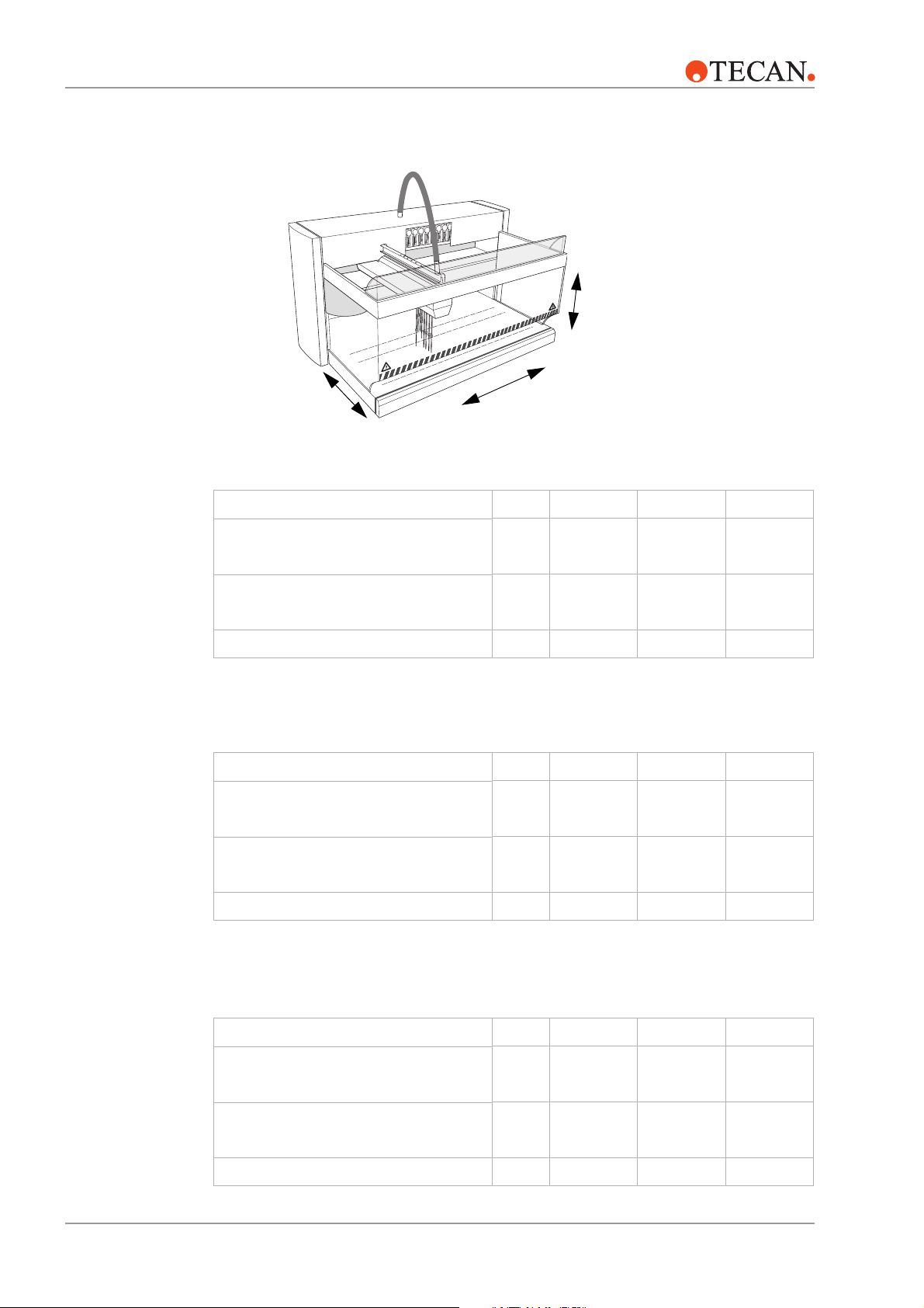
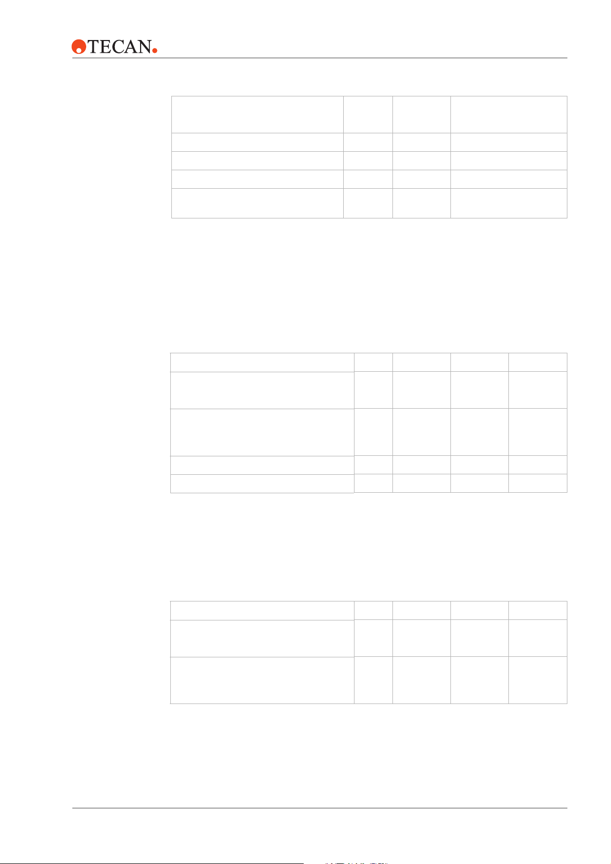
Worktable
Dimensions
Z
Y
Genesis RSP
Accessible X-range (X-travel) mm
Accessible Y-range (Y-travel) mm
Grid positions on worktable pcs. 30 45 69
Genesis RMP
Accessible X-range (X-travel) mm
X
inch
inch
inch
RSP 100 RSP 150 RSP 200
745
29.3
418
16.5
RMP 100 RMP 150 RMP 200
550
21.6
1120
44.1
418
16.5
925
36.4
1720
67.7
418
16.5
1525
60
Accessible Y-range (Y-travel) mm
inch
Grid positions on worktable pcs. 24 39 63
Genesis RWS
RWS Logistics 100 150 200
Accessible X-range (X-travel) mm
inch
Accessible Y-range (Y-travel) mm
inch
Grid positions on worktable pcs. 30 45 69
3 – 4 Genesis RSP, RWS and RMP Service Manual – Doc ID 391895 V1.0 August 2002
418
16.5
745
29.3
418
16.5
418
16.5
1120
44.1
418
16.5
418
16.5
1720
67.7
418
16.5
Page 23
3 – Product Description
RWS Assay 150 200
Accessible X-range (X-travel) mm
Accessible Y-range (Y-travel) mm
Grid positions on worktable pcs. 43 67
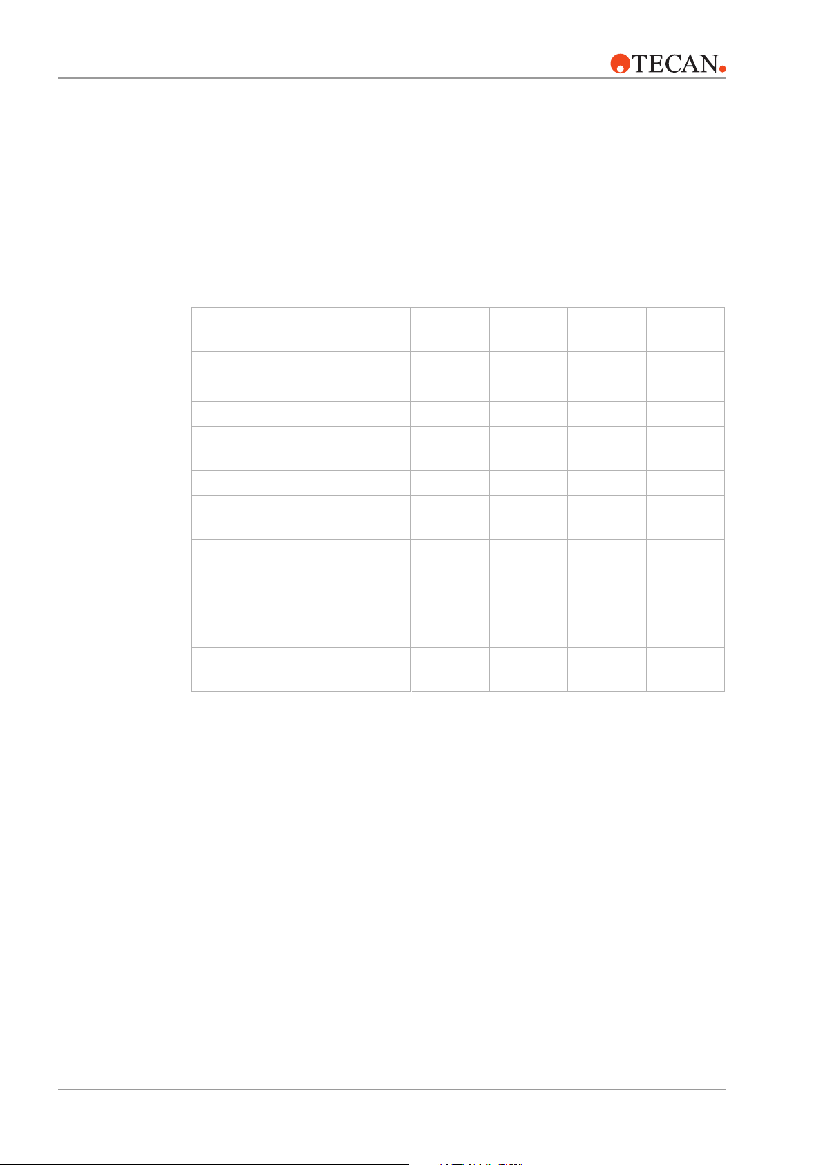
Weights Genesis RSP
Platform with 4-tip/8-tip LiHa 2 kg
RoMa 2 kg
PosID 2 option kg
MPO or FWO kg
inch
inch
lb.
lb.
lb.
lb.
925
36.4
418
16.5
RSP 100 RSP 150 RSP 200
96/103
212/227
13
18
4.4
6
8
2
115/122
253/269
6
13
11
24
2
4.4
1525
60
418
16.5
165/172
364/379
13
14
31
4.4
6
2
Packing kg
lb.
Genesis RMP
RMP 100 RMP 150 RMP 200
Platform with LiHa 2, RoMa 2 and
PosID 2
FWO kg
Packing kg
Genesis RWS
Logistics 100 150 200
Platform with 4-tip/8-tip LiHa 2 and
RoMa 2
kg
lb.
lb.
lb.
kg
lb.
35
77
166
366
4.4
104/111
229/245
2
47
104
188
414
4.4
43
95
123/130
271/287
156
241
531
2
218
173/180
381/397
71
2
4.4
99
PosID 2 option kg
lb.
August 2002 Genesis RSP, RWS and RMP Service Manual – Doc ID 391895 V1.0 3 – 5
18
8
11
24
14
31
Page 24
3 – Product Description
Logistics 100 150 200
MPO or FWO kg
lb.
Packing kg
lb.
4.4
35
77
2
4.4
47
104
2
4.4
71
156
Assay 150 200
Platform with 4-tip/8-tip LiHa 2 and
RoMa 2
PosID 2 option kg
MPO or FWO kg
Packing kg
kg
lb.
lb.
lb.
lb.
131/138
289/304
11
24
4.4
50
110
181/188
397/414
14
31
2
4.4
74
163
2
2
3.1.2 Supply Ratings
Genesis RSP
Genesis RMP
Supply ratings RSP 100 RSP 150/200
Primary voltage V AC 100–240 100–240
Frequency Hz 50/60 50/60
Power VA 800 800
Module type
(for power module supplied as of September 2001)
PM 1 PM 4
Supply ratings RMP 100/150/200
Primary voltage V AC 100–240
Frequency Hz 50/60
Power VA 1000
3 – 6 Genesis RSP, RWS and RMP Service Manual – Doc ID 391895 V1.0 August 2002
Page 25
Genesis RWS
Supply ratings RWS 100
3 – Product Description
RWS 150/200
Operating
Conditions
Primary voltage V AC 100–240 100–240
Frequency Hz 50/60 50/60
Power VA 800 1200
Module type
(for power module supplied as of September 2001)
3.1.3 Environmental Conditions
The Genesis RSP, RMP or RWS instruments are intended for indoor operation and
storage only.
Operating temperature °C
Operating humidity
relative (non condensing)
at 30 °C/86 °F or below
Logistics
Assay/Logistics
VA PM 1 PM 2
RSP RMP RWS
°F
15–32
59–90
18–30
65–86
% 30–80 30–80 30–80
18–30
65–86
Storage
Conditions
Pollution degree 2 2 2
Over voltage category class 2 2 2
Protect the instrument against dust and debris with a cover.
Recommendation: store the instrument in its original packaging. Store all manuals and
the Service and Maintenance Logbook with the instrument.
RSP RMP RWS
Storage temperature °C
°F
Storage humidity
% 30–80 30–80 30–80
1–60
34–140
1–60
34–140
1–60
34–140
relative (non condensing)
at 30 °C/86 °F or below
August 2002 Genesis RSP, RWS and RMP Service Manual – Doc ID 391895 V1.0 3 – 7
Page 26
3 – Product Description
3.1.4 Computer and Software Requirements
Computer
Hardware
Software It is strongly recommended to use the latest software versions. Please contact your
Refer to the Genesis Instrument Software Manual for details on minimum computer
requirements.
nearest Tecan representative for more information.
Software RSP RMP RWS
Logistics
Operating System X
X
Genesis Instrument SoftwareXXXX
Logic
(Clinical Diagnostics)
Gemini (Life Science) X X X
TOPS
(Operating SW)
FACTS
(Event scheduling SW)
X
X
X
X
X
X
XX
RWS
Assay
X
X
TAURUS
(Database for Clinical
Diagnostics)
Magellan
(Data reducing SW)
X = required or available for respective instrument
X
3.1.5 Additional Data for System Modules
LiHa 2 • 4 or 8 tips (diluters) acting independently
• Variable tip spacing: 9–38 mm
• Arm movement speed: 300–500 mm/s
• Positioning precision: better than 0.4 mm
RoMa 2 • Transports any rack in MP-format
X
• Arm movement speed: 400 mm/s
• Rotation: 270°
3 – 8 Genesis RSP, RWS and RMP Service Manual – Doc ID 391895 V1.0 August 2002
Page 27

• Lifting force: up to 4 N (transportable mass up to 0.4 kg
• Software adjustable gripper force: 1–4 N
• Gripper space range 55 to 140 mm
PosID 2 • Laser class 2
• Wave length: 670 nm
• Distinction between sample barcode/no barcode/no tube
• Reads vertically and horizontally
• Movement speed: 400 mm/s
• Barcode types:
Code 39 (length 0...32)
Code 39 full ASCII
Codabar (length 0...32)
Code 128 (length 0...32)
2/5 Interleaved (length 0...30, even only)
UPC-A (length not setable: 12)
UPC-E (length not setable: 8)
EAN-8 (length not setable: 8)
EAN13 (length not setable: 13)
3 – Product Description
3.2 Compatibility Matrix
Tecan customer support provides a compatibility maxtrix which displays the most
common configurations that may be installed presently on your customer’s systems.
Please request your up-to-date copy via expertline-eu@tecan.com.
August 2002 Genesis RSP, RWS and RMP Service Manual – Doc ID 391895 V1.0 3 – 9
Page 28

3 – Product Description
3 – 10 Genesis RSP, RWS and RMP Service Manual – Doc ID 391895 V1.0 August 2002
Page 29
4 Transport and Installation
4 – Transport and Installation
Purpose of This
Chapter
Chapter Overview This chapter consists of the following sections:
This chapter summarizes the procedures needed for installation of a Genesis RSP,
RMP or RWS instrument from site inspection to site acceptance.
Section Title Page
4.1 Site Inspection 4 – 1
4.2 Transport 4 – 2
4.3 Installation 4 – 3
4.3.1 Unpacking and Positioning 4 – 3
4.3.2 RMP Specific Installation Tasks 4 – 3
4.3.3 RWS Specific Installation Tasks 4 – 13
4.3.4 Further Options and Modules for RSP/RWS 4 – 14
4.3.5 Computer, Software 4 – 15
4.4 Commissioning 4 – 16
4.5 Conformity Assessment and CE Marking for RWS 4 – 18
4.6 Site Acceptance 4 – 18
4.1 Site Inspection
Site Requirements Check the customer’s site for site requirements suitable concerning the respective
instrument:
Notice the dimensions and weights of the different instruments (see section 3.1.1).
Delivery Route
• Loading dock present?
• Load capacity and size of elevator sufficient?
• Door and entrance openings, passageway corners: big enough?
Environmental Requirements
• Check according to Section 3.1.3, ‘Environmental Conditions’.
August 2002 Genesis RSP, RWS and RMP Service Manual – Doc ID 391895 V1.0 4 – 1
Page 30

4 – Transport and Installation
Space
• Enough space to place instrument and possible extensions?
• Enough space to open safety panels and access doors of the instrument?
• Enough walking space around the instrument?
• Space for placing system liquid/waste bottles?
• Enough space for the control computer?
Supply
Notice the power supply requirements (refer to section Section 3.1.2, ‘Supply Ratings’)
Check presence of power sockets for
• Instrument
•Computer
• Other modules
Date of Delivery • Determine the date of delivery.
4.2 Transport
General Notes • The Genesis RSP, RMP and RWS are precision instruments. Handle with care. Do
not expose to excessive shock.
• Always use original packaging for shipping the instrument.
Visual Check • Visually check the crate(s) for damage sustained during transportation. If such are
found, the customer must immediately file a complaint with the transport agency.
• Tecan instrument packaging is designed to avoid damage during transportation.
Please inform Tecan about all occurrences of transportation damages. Such
information is important for further improvements.
4 – 2 Genesis RSP, RWS and RMP Service Manual – Doc ID 391895 V1.0 August 2002
Page 31

4.3 Installation
4.3.1 Unpacking and Positioning
Transport handles
Figure 4-1 Transport handles – seen from below
• For exact positioning: always lift the instrument; do not shift it.
4 – Transport and Installation
1 Unpack all components and visually
check for any damage. Leave transport
paddings and moorings in place.
2 Check if the shipment is in compliance
with the packing list.
3 Lift the instrument onto the assigned
work bench and place it as required.
• Because of the considerable weight of the instrument (see Section 3.1.1,
‘Dimensions and Weights’), up to four people are required for lifting the instrument.
The center of gravity is at the rear right side of the instrument. Make sure that the
two strongest persons lift the rear of the instrument.
• Use the optional transport handles (see Figure 4-1). Never lift the instrument by the
lateral worktable covers. The screws holding the covers are not designed to support
the instrument weight.
4 Remove all transport paddings and moorings.
Packing material shall be stored for possible shipment of parts to be repaired by
manufacturers.
4.3.2 RMP Specific Installation Tasks
Add-On Module Only the RMP 200 has a separate add-on module. RMP 100 and 150 consist of one-
piece frames. Therefore, following procedure applies to RMP 200 only.
Refer to Figure 4-2, ‘RMP 200’ and Figure 4-3, ‘Add-on module assembly’.
1 Place a spirit level onto the RMP worktable and level horizontally by means of the
supports below the instrument frame.
2 Connect the add-on module (15) to the right side of the RMP 200.
There are two positioning pins (15-01) in the add-on module frame and two
positioning holes in the instrument frame.
While positioning the add-on module, lead the cables for the mains power switch
and the control lamp trough the upper left part of the add-on module.
August 2002 Genesis RSP, RWS and RMP Service Manual – Doc ID 391895 V1.0 4 – 3
Page 32

4 – Transport and Installation
Control lamp cable
Figure 4-2 RMP 200
3 Turn the two left supports (15-02) to their topmost positions, so that they do not
touch the work bench. The add-on module is now sitting on its two right supports
with the two positioning pins connected to the RMP 200.
Mains power switch cable
Uniport cable
Incubator/shaker cable
4 Turn the two left supports down until they touch the work bench.
5 Insert the module worktable (15-03).
15
15-01
15-02
15-03
Figure 4-3 Add-on module assembly
15 Add-on module
15-01 Positioning pin
15-02 Support
15-03 Module worktable
4 – 4 Genesis RSP, RWS and RMP Service Manual – Doc ID 391895 V1.0 August 2002
Page 33

4 – Transport and Installation
6 Insert the fixing screws and the two
distance washers (15-04) according to
Figure 4-4. Tighten the fixing screws.
7 Check horizontal alignment with a spirit
M4x12
6x M4x20
15-03
4x M4x16
level; if necessary, adjust by means of
M4x6
M4x6
15-04
Figure 4-4 Module worktable
the two right supports (15-02).
15-03 Module worktable
15-04 Distance washer
Set the mains power switch to off and disconnect the mains power connection of
the instrument before performing any further work!
Observe precautions for handling electrostatic discharge sensitive devices.
Wear a wrist strap.
#3
#4
8 Open the right access door (6) and
install the mains power switch (33-02)
A
33-07
into the add-on module.
Note the correct orientation of the
switch according to Figure 4-5!
9 Connect the mains power cable (33-07)
to the power switch (33-02) according
to the installation diagram (33-06) on
33-02
correct
P2P1
view A
33-06
33-05
the housing.
33-08
33-06
Washer
Figure 4-5 Electric connections for RMP
33-07
33-05
10 Fix the earth cable (33-05) to the add-
on module frame as shown in Figure
4-5.
11 Connect the control lamp cable (33-08)
to the power control lamp in the add-on
module.
12 Connect the Uniport cable coming from
the Optibo to the Uniport (see Figure
4-6, ‘Cable connections on Supervisor
and Uniport board’).
The Uniport is located in the rear part of
the add-on module.
33-02 Power switch
33-05 Earth cable
33-06 Installation diagram
33-07 Mains power cable
33-08 Control lamp cable
August 2002 Genesis RSP, RWS and RMP Service Manual – Doc ID 391895 V1.0 4 – 5
Page 34

4 – Transport and Installation
Alarm device J25
2nd RT incubator
J16, J17, J12
RT incubator
Balance
OEM
Washer
Reader
from Optibo
Figure 4-6 Cable connections on Supervisor and Uniport board
Supervisor board
Waste (LICOS)
System Liquid (LICOS)
J5 Niveau (H-sensor)
Uniport board
33-09
Figure 4-7 Connector sheet
13 Fix the connector sheet (33-09).
The connector sheet guarantees a
proper electromagnetic compatibility
(EMC).
14 Insert and fix the module cover (15-05).
15-05
Figure 4-8 Module cover
4 – 6 Genesis RSP, RWS and RMP Service Manual – Doc ID 391895 V1.0 August 2002
Page 35

Reader (Option)
19
19-02
16-06
15-07
4 – Transport and Installation
1 Remove the frame cover (15-07) from
the add-on module in order to get
easier access.
2 For RMP 200 only:
Lock the adjusting bracket (16-06) in
designated place (positioning pins)
onto the module worktable (15-03) and
fix it with the knurled screws.
3 Place the reader (19) onto the module
worktable.
4 Set selection switch (19-02) into correct
position, according to the label (19-01)
on the adjusting bracket:
• TOPS V3.0 and earlier: set switch
to “RMP mode”.
• TOPS V4.0 and later: set switch to
“Stand-alone mode”.
15-06
15-03
Figure 4-9 Reader assembly
19-03
3x M4x12
19-01
5 Put a spirit level in X-direction onto the
reader housing. If necessary, level
horizontally by means of the adjusting
wheel (15-06).
6 Connect the reader cable (19-03) to the
connection cable on the Uniport (TOPS
V3.0 and earlier) or to the second PCcom port (TOPS V4.0 and later).
15-03 Module worktable
15-06 Adjusting wheel
15-07 Frame cover
16-06 Adjusting bracket
19 Reader
19-01 Label
19-02 Selection switch
19-03 Reader cable
August 2002 Genesis RSP, RWS and RMP Service Manual – Doc ID 391895 V1.0 4 – 7
Page 36

4 – Transport and Installation
Washer (Option)
16-01
16
1 If not yet done: remove the frame cover
(Figure 4-9, 15-07) from the add-on
module in order to get easier access.
2 For RMP 200 only:
Screw the positioning rack (16-01) to
the adjusting bracket (16-06).
16-02
16-05
Figure 4-10 Washer assembly
16-06
16-04
3x M4x10/
washer
16-03
3 Place the washer (16) on the
positioning rack.
4 Check horizontal alignment with a spirit
level. If necessary, adjust by means of
the adjusting wheel (16-02).
16 Washer
16-01 Positioning rack
16-02 Adjusting wheel
16-03 Waste tubing positioning rack
16-04 Waste tubing washer
16-05 Washer cable
16-06 Adjusting bracket
5 Attach the washer cable (16-05) –
which is connected to the Uniport – to
the washer.
6 Lead the waste tubing (16-03, 16-04)
through the module frame.
4 – 8 Genesis RSP, RWS and RMP Service Manual – Doc ID 391895 V1.0 August 2002
Page 37

Heated Incubator
(Option)
4 – Transport and Installation
Installation of One Heated Incubator
1 Connect the incubator cable (20-01) to
the incubator 1 (20-A) and the Optibo.
2 Place the incubator 1 (20-A) into the
respective recesses on the module
worktable.
20-01
20-A
Figure 4-11 Heated incubator 1
4
5
3
6
2
7
1
8
0
9
F
A
E
B
D
C
20-A
3
2
1
0
F
E
20-B
20-01
20-02
3 Check horizontal alignment with a spirit
level. If necessary, adjust by means of
the supplied special key (see 17-05 in
Figure 4-13).
20-A Heated incubator 1
20-01 Incubator cable
Installation of Two Heated Incubators
4
5
6
7
8
9
A
B
D
C
1 Connect the incubator cable (20-01) to
the incubator 1 (20-A) and the Optibo.
2 Join the two incubators with the
connection cable (20-02).
3 Change address switch of incubator 2
(20-B) from #2 (= standard setting) to
#3.
4 Place the incubator 1 (20-A) into the
respective recesses on the module
worktable.
20-A
20-B
20-03
Figure 4-12 Installation of two heated incubators
5 Insert adapter plate (20-03) beneath
incubator 1 onto the worktable.
6 Place the incubator 2 (20-B) into the
recesses on the adapter plate.
7 Check horizontal alignment with a spirit
level. If necessary, adjust by means of
the supplied special key (see 17-05 in
Figure 4-13).
20-A Heated incubator 1 (address #2)
20-B Heated incubator 2, with shaker
(address #3)
20-01 Incubator cable
20-02 Connection cable
20-03 Adapter plate
August 2002 Genesis RSP, RWS and RMP Service Manual – Doc ID 391895 V1.0 4 – 9
Page 38

4 – Transport and Installation
Room
Temperature
Incubator
Installation of One RT Incubator
1 Fix the mounting bracket (17-01) with
the knurled nuts to the module
worktable.
2 Place the RT incubator 1 into the
recesses on the module worktable and
screw it to the mounting bracket.
17-02
17-01
17-03
17-03
17-02
17-A
17-04
17-01
17-A
17-B
M4x8/
washer
17-04
3 Check horizontal alignment with a spirit
level. If necessary, adjust by means of
the supplied special key (17-05).
4 Attach the incubator cable (17-02) –
which is connected to the Supervisor
board – to the incubator 1 (17-A).
17-A Room temperature incubator 1
17-B Room temperature incubator 2
17-01 Mounting bracket
17-02 Incubator cable RT1
17-03 Incubator cable RT2
17-04 Adapter plate
17-05 Special key
Installation of Two RT Incubators
(Option)
1 Place the adapter plate (17-04) onto
the worktable.
2 Fix the mounting bracket (17-01) with
the knurled nuts to the module
worktable and the adapter plate.
17-B 17-A
3 Place the RT incubator 1 into the
recesses on the module worktable and
screw it to the mounting bracket.
4 Place the RT incubator 2 into the
recesses on the adapter plate and
screw it to the mounting bracket.
5 Check horizontal alignment with a spirit
level. If necessary, adjust by means of
the supplied special key (17-05).
6 Attach the incubator cables (17-02,
17-05
17-03) – which are connected to the
Supervisor board – to the incubators.
Figure 4-13 Room temperature incubators
4 – 10 Genesis RSP, RWS and RMP Service Manual – Doc ID 391895 V1.0 August 2002
Page 39

Wash Bottle Rack
18-01
18
4 – Transport and Installation
Recommendation: As the fixing screws
(18-01) might get into contact with spilled
wash liquid, grease them to prevent from
stucking.
1 For RMP 200 only:
• Place the wash bottle rack (18) on
the module worktable and insert the
fixing screws (18-01), but do not
tighten yet.
• Mount the add-on module safety
panel.
• Make sure the wash bottle rack is
aligned parallel to the closed safety
panel.
• Tighten the fixing screws (18-01).
18
18-05
18-02
16
18-04
18-03
• Place the bottles (18-02) in the
wash bottle rack.
16 Washer
18 Wash bottle rack
18-01 Fixing screws
18-02 Bottle
18-03 Wash liquid tubing
18-04 Tubing clip
18-05 Cable
2 Connect the wash liquid tubing (18-03)
to the bottles and their respective
channels at the washer (16).
Make sure for each tubing that the
number printed on the wash bottle rack
corresponds with the one printed on the
rear of the washer.
3 Fix the tubing into tubing clip (18-04).
4 Attach the cable (18-05) marked
“Niveau” – which is connected to the
Supervisor board – to the wash bottle
rack.
5 Install the frame cover (15-07) on the
15-07
Figure 4-14 Installation of wash bottle rack
August 2002 Genesis RSP, RWS and RMP Service Manual – Doc ID 391895 V1.0 4 – 11
add-on module.
Page 40

4 – Transport and Installation
LICOS
15-08
1 For RMP 200 only:
• Insert the print cover (15-08) and fix
it with the knurled nuts.
• Place the system liquid container
(15-09) in the compartment and
connect the system liquid tubing
(white connector, leading to FWO)
and the LICOS tubing (blue
connector, leading to Supervisor
board) to the container.
• Lead the fill tubing into the system
liquid container.
LICOS
15-09
Waste
liquid
System
liquid
2 Connect waste liquid tubing, leading to
the Supervisor board, to LICOS sensor
rod. Place LICOS sensor rod into the
waste container.
15-08 Print cover
15-09 System liquid container
Figure 4-15 Installation of LICOS
Alarm Device Please refer to Installation Instructions for Alarm Device V2, Doc ID 391 255.
4 – 12 Genesis RSP, RWS and RMP Service Manual – Doc ID 391895 V1.0 August 2002
Page 41

Workstation
Extension
(RWS Assay)
4.3.3 RWS Specific Installation Tasks
16
4 – Transport and Installation
The workstation extension is an option for
RWS Assay instruments only. It is used as
support for reader and washer.
19
24
12
Figure 4-16 RWS Assay workstation extension
25
25-01
1 Install the workstation extension (25) at
the right side of the cut out worktable
(12).
2 Check horizontal alignment with a spirit
level; if necessary, adjust by means of
the two right supports (25-01).
12 Cut out work table
16 Washer
19 Reader
24 Mounting assembly for washer
25 Workstation extension
25-01 Support
Variable
Extension Deck
(RWS Logistics)
The variable extension deck is an option for RWS Logistics instruments only. It is used
as support for Ultra reader and further external devices.
The variable extension deck can either be placed on the right or on the left side of the
instrument.
Reader (Option) 1 For RWS Assay:
• Place the reader (19) onto the workstation extension (25).
For RWS Logistics:
• Install the positioning plate on the variable extension deck.
• Place the Ultra reader onto the positioning plate.
2 Connect the reader to the power supply and to PC-com port.
Washer (Option) For RWS Assay only.
1 Install the mounting assembly for washer (24) onto the workstation extension (25).
August 2002 Genesis RSP, RWS and RMP Service Manual – Doc ID 391895 V1.0 4 – 13
Page 42

4 – Transport and Installation
2 Place the washer (16) on top of the mounting assembly.
3 Check horizontal alignment with a spirit level. If necessary, adjust by means of the
mounting assembly legs.
4 Connect the washer to the power supply and to PC-com port.
5 Connect wash liquid tubing and waste tubing to the washer and respective liquid
containers.
Heated Incubator
(Option)
4.3.4 Further Options and Modules for RSP/RWS
Installation of One Heated Incubator
1 Install adapter plate onto worktable.
2 Place incubator into respective recesses on the adapter plate.
3 Connect the incubator cable to the Optibo/Optibo Power.
4 Check horizontal alignment with a spirit level. If necessary, adjust by means of the
supplied special key (see 17-05 in Figure 4-13).
Installation of Up To Four Heated Incubators
Corresponding to the workstation configuration, up to four incubators can be placed at
the rear of the worktable.
1 Install each incubator as described under Installation of One Heated Incubator.
It depends on the application software, if it is also possible to connect maximal two
incubators in series.
2 Assure proper address setting for each incubator in compliance with possibly other
options (Refer to Section 6.2.2 Jumper and Address Settings Overview).
Standard setting for one incubator is address #2.
Connecting
Options and
Modules
LICOS 1 Connect LICOS sensor tubing, leading to MPO board, to the LICOS sensor rods.
4 – 14 Genesis RSP, RWS and RMP Service Manual – Doc ID 391895 V1.0 August 2002
1 Make sure all options and modules are compatible (Refer to Section 3.2
Compatibility Matrix).
2 Assure proper address settings (Refer to Section 6.2.2 Jumper and Address
Settings Overview).
3 Prepare all options and modules according to manufacturers instructions and
connect them to Optibo/Optibo Power or Uniport or CANDI board.
2 Place LICOS sensor rods into respective containers:
• Tube 1: system liquid container
• Tube 2: waste container
3 Place system liquid container on worktable level to avoid pressure differences within
tubing system.
Page 43

4 – Transport and Installation
Access Option/
Signal Lamp
4.3.5 Computer, Software
Please refer to Installation Manual ID 392 330
1 Place the computer on the left side of the instrument. Install the computer according
to manufacturer’s instructions.
2 Make sure the instrument is switched off. Install communication cable between
computer (COM 2) and instrument (Optibo or Optibo Power).
3 Install Genesis instrument software and – if necessary – perform firmware download
(refer to Genesis Instrument Software Manual Doc ID 390 791).
4 Install respective application software.
August 2002 Genesis RSP, RWS and RMP Service Manual – Doc ID 391895 V1.0 4 – 15
Page 44

4 – Transport and Installation
4.4 Commissioning
Mechanical
Checks
Quick Jumper
Settings Test
Retightening
Screws
Manually check smooth movement of the LiHa 2 and – if installed – RoMa 2 and
PosID 2.
If there is any resistance in the movement, check for dirt residue and clean thoroughly.
Control CAN-bus resistance to check correct jumper settings (see Section 6.2.3, ‘CAN-
Bus Resistance Test’).
1 Tighten all power cable screws on the
Optibo/Optibo Power (left access door).
2 Tighten all ILID plug fixing screws.
Make Liquid
System Ready
for Use
Figure 4-17 Retightening screws
1 Tighten tubing connections and the
syringe screw on diluters.
For these tasks, a better result is
achieved when the valves with syringes
are removed from the diluters.
2 Tighten tubing connections on
distributors (top cover).
3 Mount tips.
4 Open worktable front cover (10),
remove sealing strip. Place wash
station on the worktable. Cut the
sealing strip at the appropriate length
and reinsert.
Figure 4-18 Diluter
Power-on 1 Connect the instrument to the mains.
2 Set mains power switch to on.
4 – 16 Genesis RSP, RWS and RMP Service Manual – Doc ID 391895 V1.0 August 2002
Page 45

4 – Transport and Installation
Check Readiness
for Operation
Cleaning Check the whole system for dirt residue resulting from transport and installation.
1 According to the document Installation Qualification, Doc ID 391 180, perform Setup
& Service software module.
2 Perform calibration process according to document Operation Qualification, Doc ID
391 182.
Observe appropriate sections in the Operating Manual.
August 2002 Genesis RSP, RWS and RMP Service Manual – Doc ID 391895 V1.0 4 – 17
Page 46

4 – Transport and Installation
4.5 Conformity Assessment and CE Marking for RWS
Legal Situation Genesis RWS is an open and flexible platform providing our clients with many
configuration possibilities. A Genesis RWS instrument is considered as sub-assembly
that must be integrated into a complete system. Each system has to be assessed and
investigated to comply with particular local requirements.
The openness of the Genesis RWS system makes it impossible to declare it as CE
conform and affix the corresponding label.
Responsibility A system integrator is a legal person (e.g. a RO within Tecan group or a distributor) who
acts in legal sense between Tecan Schweiz AG (manufacturer of sub-assembly) and
the end-user of the system. The system integrator takes the responsibility of a remanufacturer for the whole system and must fulfill the following points:
1 Description of complete system (product)
2 Draw up (technical file)
3 Assure conformity to local regulations
4 Declare Conformity
5 Affix CE-marking (within EU-region only)
Tecan Schweiz AG can provide support to help system integrators with points 2, 3, 4
and 5 above.
Safety Standards Please note that Genesis RWS Instruments meet the following:
• Safety requirements for laboratory equipment
EN 61010-1 / UL 3101-1 / CSA C22.2 No 1010-1
except Part 5 and 7, which are met only in part due to the open nature of the
instrument
• EMC requirements for laboratory equipment
EN 50081-1, part 1
EN 50082-1, part 1
The above is stated in the manufacturer’s declaration.
4.6 Site Acceptance
Completion 1 In case of a RWS instrument: make a conformity declaration.
2 Fill out the Acceptance Protocol (Doc ID 391 825) and have it signed by the
customer.
4 – 18 Genesis RSP, RWS and RMP Service Manual – Doc ID 391895 V1.0 August 2002
Page 47

5 Maintenance
5 – Maintenance
Purpose of This
Chapter
This chapter summarizes the preventive maintenance activities intended to retain the
Genesis RSP, RMP or RWS instrument in a state in which it maintains the required or
specified performance.
5.1 Concerning Your Safety
Decontamination Depending on the application, the instrument may be contaminated with compounds
hazardous to your health.
WARNING
The instrument may be contaminated. Before performing any maintenance or repair
tasks:
• Make sure that the instrument has been decontaminated by an expert according to
standard laboratory regulations.
• Request a filled out and signed Decontamination Declaration (Doc ID 390 901)
Unless otherwise noted, always switch off power and disconnect from mains before
carrying out any maintenance tasks.
5.2 Consumables
Cleaning Agents
ATTENTION
Strong detergents may dissolve carrier and worktable surface coatings.
Use only cleaning agents that are recommended by Tecan and according to table
Cleaning in Section 5.3.2.
Alcohol
Use ethyl-alcohol or 2-Propanol (Isopropanol).
Water
Use distilled or de-ionized water.
Bleach
Use sodium hypochlorite solution, max. 6 %.
Detergent
Use a weak detergent like
• RoboScrub
®
, order through Tecan US (order number 70-736 for 16 oz. bottle) or
August 2002 Genesis RSP, RWS and RMP Service Manual – Doc ID 391895 V1.0 5 – 1
Page 48

5 – Maintenance
• CLEAN SYSTEM, order through Tecan-D:
Daily System Clear = to clean the system daily = order number 30000938 (250 ml),
Setup Clean = to clean contaminated systems = order number, 30000937 (500 ml),
Protolyse = to clean the system from proteins = order number 30000939 (1000 ml),
Carrystop = against carryover = order number 30000940 (1000 ml).
Cleaning Material Use lint-free tissue only.
5.3 Maintenance Schedule
Spare Parts For spare parts list with part numbers refer to Chapter 7, ‘Check Lists Spare Parts’.
• Use original Tecan spare parts only.
General
Note
Spare parts must correspond to the technical requirements laid down by the
manufacturer.
5.3.1 Daily/Weekly Maintenance
For daily and weekly maintenance please follow the descriptions in the document Daily/
Weekly Maintenance Checklist, Doc ID 391 193. Check off the appropriate boxes as
you go through the maintenance tasks.
5.3.2 Half-Yearly Maintenance
Refer to document Preventive Maintenance Checklist, Doc ID 391 181 and check off
the appropriate boxes as you go through the maintenance tasks.
Task
Print out system information
Run counter read out
5 – 2 Genesis RSP, RWS and RMP Service Manual – Doc ID 391895 V1.0 August 2002
Page 49

Parts to Be
Replaced
5 – Maintenance
Part Interval: 6 month or … Refer to …
ILID cables after 250,000 Z-moves Section 6.6.4
DiTi cone and tubing
extension
Washer tubing
Adjustment
Part Interval: 6 month or … Refer to …
RoMa 1 Z-brake Section 6.7.12
Cleaning Clean every 6 month or when necessary:
Instrument part Cleaning agent/material
Liquid system, waste system Water, alcohol, weak detergent
Worktable Alcohol, weak detergent, bleach 6 %
Metal parts Alcohol
Arm guide rail, guide rollers of LiHa, RoMa Alcohol
Z-rods RoMa Lint-free tissue (do not use any agent)
after 250,000 Z-moves
Test to Be
Performed
Z-rods LiHa Lint-free tissue (do not use any agent)
Carriers Alcohol, weak detergent, bleach 6 %
Racks Alcohol, weak detergent, bleach 6 %
Tips Alcohol, bleach 6 %
DiTi cones Alcohol
PosID scanner head laser beam output
window
Washer manifold Supplied cleaning needles, water
Reader optic (filter) Optical cleaning solution (lens tissue
Perform every 6 month:
Tes t
Reference position LiHa
Alcohol
or
Ultrasonic bath, water
recommended)
Reference position RoMa (for RSP and RWS only)
Check tip adapter function
August 2002 Genesis RSP, RWS and RMP Service Manual – Doc ID 391895 V1.0 5 – 3
Page 50

5 – Maintenance
5.3.3 Yearly Maintenance
Fill/flush system
Disposable tips
Liquid detection test
LICOS test
PosID test
Washer: prime each washer channel
Reader: QC test
Door lock test
Refer to document Preventive Maintenance Checklist, Doc ID 391 181 and check off
the appropriate boxes as you go through the maintenance tasks.
General Perform the half-yearly maintenance tasks as listed in Section 5.3.2.
Parts to be
Replaced
Test to Be
Performed
Part Interval: 12 month or … Refer to …
Syringes after 1 million moves Section 6.4.3
3-way valve of diluter after 1 million moves Section 6.4.3
Tips
Aspirating tubing Section 6.4.2
Interconnecting tubing Section 6.4.2
Pipetting tubing Section 6.4.2
Waste tubing Section 6.4.2
Perform every 12 month:
Test
Precision test
5 – 4 Genesis RSP, RWS and RMP Service Manual – Doc ID 391895 V1.0 August 2002
Page 51

6 – Replacement of Spare Parts, Repair
6 Replacement of Spare Parts, Repair
Purpose of This
Chapter
Chapter Overview This chapter consists of the following sections:
This chapter describes the activities carried out after a failure has occurred, intended to
restore an item to a state in which it can perform its required function.
Section Title Page
6.1 General Notes on Repair 6 – 4
6.1.1 Concerning Your Safety 6 – 4
6.1.2 General Repair Tasks 6 – 5
6.1.3 Operating Tests after Repair 6 – 6
6.2 Abstract of Important Data 6 – 7
6.2.1 Special Tools 6 – 7
6.2.2 Jumper and Address Settings Overview 6 – 8
6.2.3 CAN-Bus Resistance Test 6 – 10
6.2.4 Software Error Messages 6 – 11
6.3 Instrument – Disassembly and Assembly Procedures 6 – 22
6.3.1 Worktable 6 – 22
6.3.2 Door Locks 6 – 24
6.3.3 X-Drive Assembly 6 – 25
6.3.4 Power Modules 6 – 34
6.3.5 Electronic Boards 6 – 37
6.4 Liquid System – Disassembly and Assembly Procedures 6 – 46
6.4.1 Overview 6 – 46
6.4.2 Tubing System 6 – 47
6.4.3 Diluter and Dilback 6 – 50
6.4.4 MPO/FWO 6 – 54
6.4.5 Low Volume Option 6 – 62
6.4.6 6-Way Valve Option 6 – 69
6.5 LiHa 1 – Disassembly and Assembly Procedures 6 – 73
6.5.1 Overview 6 – 73
6.5.2 Complete LiHa 1 Assembly 6 – 75
6.5.3 X-Flex Cable 6 – 76
6.5.4 ILID Cable 6 – 76
6.5.5 ILID Flat Cable 6 – 76
6.5.6 Electronic Boards for LiHa 1 6 – 78
August 2002 Genesis RSP, RWS and RMP Service Manual – Doc ID 391895 V1.0 6 – 1
Page 52

6 – Replacement of Spare Parts, Repair
Section Title Page
6.5.7 Y-Belt and Y-Spreading Belt 6 – 79
6.5.8 Y-Motor and Y-Spreading Motor 6 – 80
6.5.9 Tip Adapter 6 – 81
6.5.10 Ensure Operating Readiness 6 – 81
6.6 LiHa 2 – Disassembly and Assembly Procedures 6 – 83
6.6.1 Overview 6 – 83
6.6.2 Complete LiHa 2 Assembly 6 – 85
6.6.3 X-Flex Cable 6 – 88
6.6.4 ILID Cable 6 – 89
6.6.5 ILID Flat Cable 6 – 90
6.6.6 Electronic Boards for LiHa 2 6 – 91
6.6.7 Y-Belt and Y-Spreading Belt 6 – 95
6.6.8 Y-Motor and Y-Spreading Motor 6 – 97
6.6.9 Tip Adapter 6 – 98
6.6.10 Lower DiTi Eject Option 6 – 99
6.6.11 Ensure Operating Readiness 6 – 104
6.7 RoMa 1 – Disassembly and Assembly Procedures 6 – 106
6.7.1 Overview 6 – 106
6.7.2 Complete RoMa 1 Assembly 6 – 109
6.7.3 Gripper Fingers 6 – 109
6.7.4 Gripper Module Head, Gripper Board 6 – 109
6.7.5 Rotator Motor 6 – 110
6.7.6 X-Flex Cable 6 – 110
6.7.7 Gripper/Rotator Flex Cables 6 – 110
6.7.8 Y/R- and Z/G-DC-Servo Board 6 – 110
6.7.9 RoMa 1 Backplane 6 – 111
6.7.10 Y-Belt 6 – 111
6.7.11 Y- and Z-Motor 6 – 111
6.7.12 Z-Brake 6 – 112
6.7.13 Ensuring Operating Readiness 6 – 113
6.8 RoMa 2 – Disassembly and Assembly Procedures 6 – 114
6.8.1 Overview 6 – 114
6.8.2 Complete RoMa 2 Assembly 6 – 117
6.8.3 Mechanical Adjustment After Reinstallation 6 – 118
6.8.4 Gripper Fingers 6 – 121
6.8.5 Gripper Module Head, Gripper Board 6 – 122
6.8.6 Rotator Motor 6 – 125
6 – 2 Genesis RSP, RWS and RMP Service Manual – Doc ID 391895 V1.0 August 2002
Page 53

6 – Replacement of Spare Parts, Repair
Section Title Page
6.8.7 X-Flex Cable 6 – 126
6.8.8 Gripper/Rotator Flex Cables 6 – 129
6.8.9 Y/R- and Z/G-DC-Servo Board 6 – 131
6.8.10 RoMa 2 Backplane 6 – 132
6.8.11 Y-Belt 6 – 133
6.8.12 Y-Motor 6 – 135
6.8.13 Z-Motor 6 – 136
6.8.14 Z-Brake 6 – 137
6.8.15 Ensuring Operating Readiness 6 – 138
6.9 PosID 1 – Disassembly and Assembly Procedures 6 – 139
6.9.1 Complete PosID 1 Assembly 6 – 139
6.9.2 X-Drive Assembly (X-Belt, X-Motor, X-Flex Cable) 6 – 140
6.9.3 Electronic Boards for PosID 1 6 – 141
6.9.4 Scanner Assembly (Scanner Head, B-Motor) 6 – 144
6.9.5 Y-Belt Assembly (Y-Belt, Y-Motor) 6 – 146
6.9.6 No Tube Sensor 6 – 147
6.9.7 Ensure Operating Readiness 6 – 148
6.10 PosID 2 – Disassembly and Assembly Procedures 6 – 149
6.10.1 Complete PosID 2 Assembly 6 – 150
6.10.2 X-Drive Assembly (X-Belt, X-Motor, X-Flex Cable) 6 – 153
6.10.3 Electronic Boards for PosID 2 6 – 155
6.10.4 Scanner Assembly (B-Motor, Scanner Head and
Cable)
6.10.5 Y-Drive Assembly (Y-Belt, Gripper Assembly, YMotor)
6.10.6 No Tube Sensor 6 – 161
6.10.7 Ensure Operating Readiness 6 – 162
6 – 157
6 – 159
August 2002 Genesis RSP, RWS and RMP Service Manual – Doc ID 391895 V1.0 6 – 3
Page 54

6 – Replacement of Spare Parts, Repair
6.1 General Notes on Repair
Useful References • Refer to Chapter 8, ‘Instruments at a Glance’ for an overview concerning the
location of the most common parts.
• For spare parts list with part numbers refer to Chapter 7, ‘Check Lists Spare Parts’.
•As Chapter 7 is structured in the sequence of disassembly of an item, it can also be
used by experienced FSEs as brief instructions.
• For electrical diagrams refer to Chapter 9, ‘Diagrams’.
Spare Parts • Use original Tecan spare parts only.
Note
Spare parts must correspond to the technical requirements laid down by the
manufacturer.
Disposal of Waste • Dispose used items and consumables according to the relevant national
environmental, health and safety laws and regulations.
6.1.1 Concerning Your Safety
Chemical,
Biological and
Radioactive
Hazards
Decontamination For your own and any other affected person’s safety, make sure the instrument or parts
Depending on the applications, parts of the instrument may have been in contact with
biohazardous, poisonous or even radioactive materials. A potential risk may arise from
the liquids that have been handled on the instrument.
• Strictly apply appropriate safety precautions according to general laboratory and
applicable local, state and federal regulations.
WARNING
Potential Biohazard. The instrument might be contaminated! For servicing, use
appropriate personal protective equipment!
have been thoroughly decontaminated prior to carrying out any maintenance and repair
task on the instrument or before sending it or parts of it for repair:
• Thoroughly clean and decontaminate all relevant parts.
• Provide a filled-out and signed Decontamination Declaration (Doc ID 390 901).
6 – 4 Genesis RSP, RWS and RMP Service Manual – Doc ID 391895 V1.0 August 2002
Page 55

Electrical Shock
Hazard
6 – Replacement of Spare Parts, Repair
WARNING
Unless otherwise noted, always switch off power and disconnect from mains before
carrying out any tasks described in this chapter.
Electrostatic
Sensitive Devices
Discharge static electricity from your body by wearing a wrist strap to protect yourself
and sensitive control electronics installed:
• Wear a wrist strap during all installation and maintenance tasks, e.g. when
exchanging components.
ATTENTION
Observe precautions for handling electrostatic discharge sensitive devices.
6.1.2 General Repair Tasks
Loctite® 638 • Several set screws are glued with Loctite 638. Use a hot-air apparatus to soften the
adhesive before unscrewing these screws.
Disconnecting
Cables
• When disconnecting cables, always mark designation (Jxx) on connector using a
water resistant pen.
If due to insufficient space, designations
are not marked on the PCB use electrical
diagrams instead.
Figure 6-1 Connector designation
When replacing
any PCB …
Cleaning • Wipe off grease residue and thoroughly clean affected instrument parts after any
• Make sure the jumpers for CAN-bus resistance are set identically to the replaced
PCB (see also Section 6.2.2, ‘Jumper and Address Settings Overview’).
• Control if address switch is set correctly (see Section 6.2.2, ‘Jumper and Address
Settings Overview’).
• Check CAN-bus resistance (see Section 6.2.3, ‘CAN-Bus Resistance Test’).
repair task.
August 2002 Genesis RSP, RWS and RMP Service Manual – Doc ID 391895 V1.0 6 – 5
Page 56

6 – Replacement of Spare Parts, Repair
6.1.3 Operating Tests after Repair
Service Checklist • After replacing or removing and reinstalling modules or spare parts, carry out the
appropriate tests according to Service Checklist Doc ID 391 183 (included in the
Genesis Maintenance and Service Logbook).
6 – 6 Genesis RSP, RWS and RMP Service Manual – Doc ID 391895 V1.0 August 2002
Page 57

6.2 Abstract of Important Data
6.2.1 Special Tools
LiHa reference tip Part No. 612 503
384 well tip adjustment tool Part No. 613 103
6 – Replacement of Spare Parts, Repair
RoMa calibration tool Part No. 612 622
RoMa teach plate Part No. 613 101
PosID service rack Part No. 613 100
August 2002 Genesis RSP, RWS and RMP Service Manual – Doc ID 391895 V1.0 6 – 7
Page 58

6 – Replacement of Spare Parts, Repair
6.2.2 Jumper and Address Settings Overview
The following communication overview shows …
• the default address settings on the electronic boards of the different modules,
• on which modules the jumpers have to be set/switched on, or removed/switched off
according to the configuration of the instrument:
Communication
Overview
RS 232
RS 232
PC
RS 232 / RS 232
Multiport 8x RS232
Washer
Reader
Z/R
Liconic Carousel
Stepper Drive / Scanner
Option-Can
O7
Te-Shake #6
Option-Can
Te-Mags #5
O6
3
Option-Can
Te-Vacs #4
O5
3
O4
Option-Can
Te-Sonic #3
Option-Can
O3
Incubator #2
3 2
SMIO #1
O2
Option-Can
6
MPO #0
O1
Option-Can
#0
Can
DC-
ST5
Local-
Servo
5
Option-Can
T1..T6
TEMPO #8..D
7
O2
Option-Can
Te-Flow #1
5
V1
Option-Can
LOW-VOLUME
O7
V2
O2
U1..4
Q1...8 S1..8
...4
T1
7 2
4
RMP
4
1
2
RSP
9
Option-Can
Option-Can
Option-Can
Option-Can
Option-Can
Local-
Local-
Option-Can
Te-Stack #0...F
WRC (2) #6
6-way valve
Supervisor #1
Uniport
position)
(depending on
TeMo #0
Can
DC-
Servo
Can
DC-
Servo
#1
#0
Local-
T3TR6
Can
2
The Device default number and name, i.e. O5 as device is identified in FW
The Device default adress, i.e. #4. Setting for the adress switch
Some configurations may require different adress settings.
#0
DC-
Servo
Option-Can
WRC (1) #6
= always open (Switch off or Jumper not set)
= always terminated if the module is installed (Switch on or Jumper set)
O5
The termination of the option-CAN and the system-CAN is priorized
depending on configuration:
Option-Can
The two installed modules with the lowest numbers / letters within the box
have to be terminated:
{
Vacs #4
= priorized termination of Option CANA= priorized termination of System CAN
1
CU
RS-232
M1
Can
DC-
System-
Optibo
MO2
D 9
System-Can Option-Can
#5
#7
Can
D8
Diluter
System-
#6
Can
D7
Diluter
System-
#5
Can
D6
Diluter
System-
#4
Can
D5
Diluter
System-Can
Diluter Backplane
System-
#3
Can
D4
Diluter
System-
#2
Can
D3
Diluter
System-
#1
Can
D2
Diluter
System-
#0
Can
D1
Diluter
System-
C
E 9
Servo
8
Option-Can
P1
CU PosID2
#0
Can
DC-
MO1
Local-
Servo
#4
Can
DC-
MO5
Servo
System-
#3
Can
DC-
MO4
Servo
System-
B
System-Can
A1
Backplane (LiHa)
Can
System-
Can
System-
Can
System-
DC-
DC-
DC-
#2
MO3
Servo
#1
MO2
Servo
#0
MO1
Servo
Scanner
Y/B PosID
Local-Can / RS232
#2
Can
DC-
MO2
Local-
Servo
#7
Can
DC-
MO1
Servo
RoMa
Backplane
System-
Can
System-
DC-
#6
MO2
Servo
A
R1
System-Can
6 – 8 Genesis RSP, RWS and RMP Service Manual – Doc ID 391895 V1.0 August 2002
Page 59

Jumper Allocation
6 – Replacement of Spare Parts, Repair
PCP System
CAN-bus
Optibo, Optibo Power J12 J13 —
CU board J1 J22
Option
CAN-bus
Local
CAN-bus
MPO board V2.0
MPO board V3.1/V4.0
LiHa backplane J14 — —
Dilback J10 — —
RoMa 1 backplane
RoMa 2 backplane
PosID 1/PosID 2 CU board — J8 J6
—
—
J2
J1
J4
J2
—
—
—
—
—
—
August 2002 Genesis RSP, RWS and RMP Service Manual – Doc ID 391895 V1.0 6 – 9
Page 60

6 – Replacement of Spare Parts, Repair
6.2.3 CAN-Bus Resistance Test
Purpose of this test is to verify whether bus end jumper settings on control electronics
are correct.
Will Be Applicable • When commissioning a new instrument.
• After exchange or new installation of a LiHa 1/LiHa 2, RoMa 1/RoMa 2, PosID 1/
PosID 2 or other options as e.g. Te-VacS etc.
• After exchange or supplemental installation of PCBs.
Required Special
Tools
Test Procedure 1 Switch off the instrument.
•Multimeter
2 On the Optibo or Optibo Power (left access door) check the CAN-bus resistance
between the respective check points:
Figure 6-2 Check points for System CAN-bus
• System CAN
Measure resistance between CAN_L
and CAN_H.
• Option CAN
Measure resistance between CANO_L
and CANO_H.
Figure 6-3 Check points for Option CAN-bus
3 Correct CAN-bus resistance:
50–65 Ω: correct number of jumpers
< 50 Ω: too many jumpers are set
~ 40 Ω: 1 jumper too much
> 65 Ω: too few jumpers are set
~ 120 Ω: 1 jumper too few
If CAN-bus resistance is not between 50 an 65 Ω: compare jumper settings and
CAN-bus connections with ‘Communication Overview’ in Section 6.2.2, ‘Jumper and
Address Settings Overview’ and correct.
6 – 10 Genesis RSP, RWS and RMP Service Manual – Doc ID 391895 V1.0 August 2002
Page 61

6.2.4 Software Error Messages
Toolbox General
Errors
6 – Replacement of Spare Parts, Repair
Toolbox
error code
0 OK (no error)
1 Toolbox not initialized (from V2.1 on: not opened)
2 Toolbox already initialized (from V2.1 on: already open)
3 Toolbox init error (from V2.1 on: error in opening)
4 Communication driver error
5 Incorrect answer string format (cannot extract)
6 Illegal command parameter value
7 Error list contains at least one error
8 No such worktable
Explanation
9 Open rack database failed
10 Worktable access error (carrier/rack)
11 Evaluation access (not a single position defined)
12 Evaluation access (not a single position is accessible due to Y)
13 Evaluation access (position out of range)
14 Accessing all selected positions not possible
15 No carrier/rack defined
16 Worktable access error (tube)
17 Open comm log file failed
18 No carrier on specified grid position
19 Worktable object creation error
20 Open communication driver failed
21 Close communication driver failed
22 Evaluation access (not a single position is accessible due to X)
23 Genesis DB not open
24 Communication driver not open
25 Plate stuck on gripper
26 Balance initialization error
27 Balance isn't initialized
28 Balance isn't correct tared
29 Measurements not enough linear. Preparing/weighing not possible.
30 Wrong machine type. No balances available.
31 Balance not prepared. Weighing not possible.
32 Error while getting a balance value. Weighing not possible.
August 2002 Genesis RSP, RWS and RMP Service Manual – Doc ID 391895 V1.0 6 – 11
Page 62

6 – Replacement of Spare Parts, Repair
Toolbox
error code
33 Wrong machine type. No low volume support.
34 This machine has no pinch valves
35 No installable easy option available
36 Easy option slot occupied
37 Defined Easy Option module not available
38 The initialization of the serial communication port failed
39 Sending through the serial communication port failed
40 Receiving through the serial communication port failed
41 Command not implemented (for the PosID 1)
42 Command not implemented (for the PosID 2)
43 Difference too big between “prepare weigh” and “weigh” in
44 Worktable View: nothing selected
45 Worktable View: index out of range
46 Worktable View: …
Explanation
evaporation
Toolbox User
Interactions
Toolbox Data
Errors
47 Worktable View: object not created
Toolbox
error code
90 Abort from user
91 Retry from user
92 User (calling application) handles error
93 Ignore from user
94 “Go to ZBottom” from user
Toolbox
error code
101 Incorrect tip number
102 Data pointer is NULL
103 Individual tip data set (no global data available)
Explanation
Explanation
104 Incorrect liquid index
105 Data set not defined
106 Selector out of bounds
107 Not enough space (for complete report)
6 – 12 Genesis RSP, RWS and RMP Service Manual – Doc ID 391895 V1.0 August 2002
Page 63

6 – Replacement of Spare Parts, Repair
Toolbox
Communication
Errors
Toolbox Device
Errors (Ranges)
Toolbox
Explanation
error code
108 Invalid diluter number
109 Parameter value(s) out of range
110 Invalid arm ID
111 Invalid number of tips
112 Invalid number of diluters
Toolbox
Explanation
error code
201 COM unknown error
202 COM device still busy
203 COM device time-out
.
Toolbox error
code range
Device
Address
Explanation
Common Errors
for All Devices
300 Common
400 M CU
500 A LiHa
527 A LiHa (tip mounted)
600 O MPO, Incubator, Supervisor
700 D Diluter
800 P PosID
900 R RoMa
1000 V Low Volume Option
1100 U Uniport
10,000 P PosID extended errors
Toolbox error code = Toolbox error code range + Communication driver error code
Examples:
Toolbox error code 807 = 800 + 7 = PosID not initialized
Toolbox error code 528 = 527 + 1 = LiHa (tip mounted) initialization error
i
Communication
Explanation
driver error code
1 Initialization error
August 2002 Genesis RSP, RWS and RMP Service Manual – Doc ID 391895 V1.0 6 – 13
Page 64

6 – Replacement of Spare Parts, Repair
Communication
driver error code
2 Invalid command
3 Invalid operand
4 Invalid command sequence
5 Device not implemented
6 Time-out error
7 Device not initialized
8 Command overflow of CU
15 Command overflow of subdevice
CU Error Codes Toolbox error code = Toolbox error code range (= 400 for CU) + Communication driver
error code
Communication
driver error code
13 413 No access to serial EEPROM
Explanation
Toolbox
error code
Explanation
16 416 Power fail circuit error
17 417 Arm collision avoided between LiHa and
RoMa
18 418 Door lock 1 failed
19 419 Door lock 2 failed
20 420 No new device #V node detected
21 421 Device #V node already defined
LiHa Error Codes Toolbox error code = Toolbox error code range + Communication driver error code
First number = LiHa (range 500), second number = LiHa tip mounted (range 527)
Communication
driver error code
9 509/536 No liquid detected (MDT, MET)
10 510/537 Drive no load
11 511/538 Not enough liquid (MDT)
Toolbox
error code
Explanation
12 512/539 Not enough liquid (MET)
13 513/540 Arm collision avoided with PosID
16 516/543 Power fail circuit error
17 517/544 Arm collision avoided with RoMa
18 518/545 Clot limit passed (MCT)
6 – 14 Genesis RSP, RWS and RMP Service Manual – Doc ID 391895 V1.0 August 2002
Page 65

6 – Replacement of Spare Parts, Repair
Communication
driver error code
19 519/546 No clot exit detected (MCT)
20 520/547 No liquid exit detected (MDT, MET)
23 523/550 Not yet moved (MDT, MET)
24 524/551 ILID pulse error (MDT, MET, MCT)
25 525/552 Tip not fetched (AGT, ADT)
26 526/553 Tip not mounted (AGT, ADT)
27 527/554 Tip mounted (AGT, ADT)
RoMa Error Codes Toolbox error code = Toolbox error code range (= 900 for RoMa) + Communication
driver error code
Communication
driver error code
9 909 Plate not fetched (AGR)
10 910 Drive no load
Toolbox
error code
Toolbox
error code
Explanation
Explanation
16 916 Power fail circuit error
17 917 Arm collision avoided with LiHa
XP Error Codes Toolbox error code = Toolbox error code range (= 700 for Diluter) + Communication
driver error code
PosID 1 Common
Errors
Communication
driver error code
9 709 Plunger overload
10 710 Valve overload
11 711 Valve in bypass
13 713 No access to EEPROM
Toolbox error code = Toolbox error code range* + Communication driver error code
*= 800 for Communication driver error codes up to 31 and 10,000 for Communication
driver error codes beyond 31
Toolbox
error code
Explanation
Communication
driver error code
14 814 Extended error in device occurred (REE
36 10,036 EEPROM failure
August 2002 Genesis RSP, RWS and RMP Service Manual – Doc ID 391895 V1.0 6 – 15
Toolbox
error code
Explanation
reports the extended error code)
Page 66

6 – Replacement of Spare Parts, Repair
PosID 1 Axis
Errors (Ranges)
Communication
driver error code
37 10,037 EEPROM no access (hardware problem; e.g.
38 10,038 EEPROM data invalid (e.g. chip empty or
39 10,039 EEPROM special error (trap for rare error;
40 10,040 Invalid mnemonics
41 10,041 Invalid argument (parameter out-of-range)
42 10,042 Invalid parameter number
43 10,043 Invalid device address
44 10,044 Invalid frame type
45 10,045 Invalid message length
Communication
driver error code
ranges
Toolbox
error code
Explanation
Explanation
no chip available)
invalid data, system adjustment required!)
data is valid!)
PosID 1 Common
Axis Errors
100 X-axis offset (arm movement)
200 Y-axis offset (grip movement)
300 B-axis offset (barcode scanner movement)
Communication driver error code:
x = communication driver error code range
Examples:
Communication driver error code 263 = 200 + 63 = Y-axis target not reached
Communication driver error code 1324 = 300 + 1024 = B-axis overload detected
Toolbox error code = Toolbox error code range (10,000 for PosID) + Communication
driver error code
Communication
driver error code
x50 10,x50 Unknown axis mnemonic
x51 10,x51 Invalid axis identifier
Toolbox
error code
Explanation
x52 10,x52 # of sub-axis is out of limit
x55 10,x55 Collision detection is active
x58 10,x58 Time-out calculation error
6 – 16 Genesis RSP, RWS and RMP Service Manual – Doc ID 391895 V1.0 August 2002
Page 67

6 – Replacement of Spare Parts, Repair
Communication
driver error code
x59 10,x59 Dynamic read calculation error
x61 10,x61 Initialization: target not reachable
x62 10,x62 Target out-of-range
x63 10,x63 Target not reached
x65 10,x65 Axis movement time-out
1x20 11,x20 CAN over run
1x21 11,x21 No load
1x22 11,x22 No liquid detected
1x23 11,x23 Break point not reached
1x24 11,x24 Overload detected
1x25 11,x25 Delayed action pending (ready to execute)
1x26 11,x26 Delayed action pending (ready to execute)
1x27 11,x27 Command not yet implemented
1x29 11,x29 DC-Servo multiple error
Toolbox
error code
Explanation
PosID 1
Miscellaneous
Errors
Toolbox error code = Toolbox error code range (10,000 for PosID) + Communication
driver error code
BCS = Barcode Scanner; HOST = PosID CU
Communication
driver error code
401 10,401 BCS initialization: no ID REQUEST from BCS
405 10,405 Unexpected response from BCS after START
411 10,411 No decoded barcode from BCS
412 10,412 Barcode string length out-of-range
413 10,413 NR (No Read) message from BCS
421 10,421 CMNDNAK (CoMmaND Not Acknowledge)
422 10,422 No ACK or NAK respond from BCS
425 10,425 No respond from BCS
426 10,426 Checksum error detected by BCS
Toolbox
error code
Explanation
after ATTENTION from HOST
DECODE
respond from BCS
427 10,427 Unexpected respond from BCS
435 10,435 No respond from BCS
August 2002 Genesis RSP, RWS and RMP Service Manual – Doc ID 391895 V1.0 6 – 17
Page 68

6 – Replacement of Spare Parts, Repair
Communication
driver error code
436 10,436 Checksum error detected by HOST
437 10,437 Unexpected respond from BCS
438 10,438 No complete respond from BCS
441 10,441 HOST received message from wrong
451 10,451 BC type out-of-range
452 10,452 Verify mode out-of-range
455 10,455 Unexpected character in BC string
456 10,456 BC check digit error
460 10,460 Invalid test number
470 10,470 Parameter out-of-range
501 10,501 Invalid field id
502 10,502 Invalid parameter
510 10,510 Invalid sector id
511 10,511 Sector already active
Toolbox
error code
Explanation
message source
512 10,512 Sector not yet active
513 10,513 Sector parameter out-of-range
514 10,514 Sector limit reached
520 10,520 Invalid fixed field id
521 10,521 Fixed field already active
522 10,522 Fixed field not yet active
523 10,523 Fixed field parameter out-of-range
530 10,530 Unknown carrier state
531 10,531 Invalid carrier code
532 10,532 Invalid carrier code string length
533 10,533 Invalid carrier code type
534 10,534 Invalid carrier placement
535 10,535 Invalid carrier id
536 10,536 Carrier id already active
537 10,537 Carrier id not yet active
538 10,538 Invalid carrier code format
545 10,545 Invalid carrier type
546 10,546 Carrier type already active
547 10,547 Carrier type not yet active
548 10,548 Invalid carrier data id
549 10,549 Carrier is at remove position
6 – 18 Genesis RSP, RWS and RMP Service Manual – Doc ID 391895 V1.0 August 2002
Page 69

6 – Replacement of Spare Parts, Repair
Communication
driver error code
550 10,550 Unknown rack/sample state
555 10,555 Invalid rack/sample type
556 10,556 Rack/sample type already active
557 10,557 Rack/sample type not yet active
558 10,558 Invalid rack/sample data id
560 10,560 Move right carrier locked
601 10,601 Invalid port number
602 10,602 Invalid bit number
701 10,701 BC scan task not started
710 10,710 No carrier present
711 10,711 Expected carrier not found
720 10,720 Calibration Y max read
741 10,741 Reload of same carrier
742 10,742 Comparison of 1st rack/sample impossible
743 10,743 Illegal removal of carrier detected
Toolbox
error code
Explanation
744 10,744 Illegal movement of carrier detected
750 10,750 Previous BC read was equal
PosID 2 Errors Toolbox error code = Toolbox error code range (= 800 for PosID) + Communication
driver error code
Communication
driver error code
9 809 No liquid detected by DC-Servo
10 810 Drive with no load detected
11 811 Break point reached
12 812 No access to parameter block
13 813 Collision between LiHa and PosID avoided
14 814 Extended error
16 816 Power fail circuit failure
17 817 Not locked to grid
Toolbox
error code
Explanation
(error code currently not used)
18 818 Sector not defined
20 820 Barcode scanner failure (communication
problem, e.g. wrong answer to ESC
sequence)
August 2002 Genesis RSP, RWS and RMP Service Manual – Doc ID 391895 V1.0 6 – 19
Page 70

6 – Replacement of Spare Parts, Repair
Communication
driver error code
21 821 Barcode scanner communication error
22 822 Carrier not movable
23 823 Break point not reached
24 824 Carrier not defined
25 825 Rack/sample not defined
26 826 Carrier not loaded
27 827 Invalid carrier id barcode
28 828 Carrier not present
29 829 Illegal BCS movement
30 830 BCS failed during initialization
Toolbox
error code
Explanation
(transmission errors upon OV, FE, PT, VRC
cmds)
(error code currently not used)
(error code currently not used)
Low Volume
Option Errors
Incubator Errors Toolbox error code = Toolbox error code range (= 600 for incubator) + Communication
Toolbox error code = Toolbox error code range (= 1000 for Low Volume Option) +
Communication driver error code
Communication
driver error code
9 1009 Selected valve not installed
10 1010 Endless mode not possible
11 1011 Wrong node defined
driver error code
Communication
driver error coder
9 609 Shaker not installed
10 610 Shaker position initialization error
11 611 Close door solenoid short or open circuit
12 612 EEPROM checksum error
Toolbox
error code
Toolbox
error code
Explanation
Explanation
13 613 EEPROM access error
16 616 Slot temperature overrun
17 617 Temperature sensor short- or open circuit, or
suspect
18 618 Shaker fail
6 – 20 Genesis RSP, RWS and RMP Service Manual – Doc ID 391895 V1.0 August 2002
Page 71

6 – Replacement of Spare Parts, Repair
Supervisor Errors Toolbox error = Toolbox error range (= 600 for Supervisor) + Communication driver error
Communication
driver error coder
12 612 LICOS not calibrated
13 613 EEPROM access error
16 616 Door already open
17 617 Hall sensors not calibrated
Uniport Errors Spectra/Sunrise Errors
Toolbox error = Toolbox error range (= 1100 for Uniport) + Communication driver error
Communication
driver error coder
16 1116 Lamp low
17 1117 Lamp high
18 1118 Transport error
19 1119 Filter error
20 1120 Checksum error
Toolbox
error code
Toolbox
error code
Explanation
Explanation
21 1121 No data uploaded by “D” or “D2” cmd.
August 2002 Genesis RSP, RWS and RMP Service Manual – Doc ID 391895 V1.0 6 – 21
Page 72

6 – Replacement of Spare Parts, Repair
6.3 Instrument – Disassembly and Assembly Procedures
This section describes mechanical and electronic exchange routines on instrument
level.
6.3.1 Worktable
Spare Parts
Worktable
Required Special
Tool
Removal of
Worktable
For spare parts list with part numbers refer to Section 7.1.1, ‘Spare Parts Worktable’.
Following items can be replaced as spare parts:
• Worktable
• Positioning pins
• Sealing strip
• Reference tip for LiHa
Will Be Applicable …
• If a new or another type of worktable has to be installed.
• If you need to access the PosID/PosID 2 or an older version of PosID/PosID 2
CU board (located underneath the worktable).
Removal
For more information refer to Section 4.3, ‘Installation’, inverse order of installation
instructions.
1 Empty the worktable completely.
2For RMP: detach the module worktable.
3 Open the front worktable cover (10).
• For RMP: remove the door locks (21).
• For RWS: remove magnet holders.
4 Remove all screw caps (tip: use a watch maker screwdriver) and all fixing screws
from the worktable.
5 Remove the worktable by carefully lifting and pulling forward.
Installation of
Worktable
6 – 22 Genesis RSP, RWS and RMP Service Manual – Doc ID 391895 V1.0 August 2002
1 Carefully install the worktable.
2 RSP and RWS: insert the 4 countersunk screws on the rear right and rear left but do
not tighten them yet.
RMP: insert the 2 countersunk screw on the rear left but do not tighten them yet.
Page 73

6 – Replacement of Spare Parts, Repair
3 Insert but only slightly tighten the oval head screws.
4 Manually align the worktable, then tighten the front left screw.
This screw will act as a pivot point during the following alignment.
5 Install the reference tip onto the LiHa:
• 4-Tip LiHa: mount reference tip on position 1 (first tip from behind).
• 8-Tip LiHa: mount reference tip on position 3 (third tip from behind).
6 Manually position the reference tip at the edge of the foremost positioning pin in grid
position 1 (most left grid). Check the gap between pin and reference tip.
7 Manually move the LiHa to the
rightmost grid position and check the
gap between pin and reference tip.
The gap must be the same on either
side of the worktable.
Ensure Operating
Readiness
Figure 6-4 Gap between reference tip and positioning pin
8 When the worktable is positioned: tighten the fixing screws and insert the screw
caps.
9 Reinstall all previously removed parts. For detailed information about installing …
• RMP door locks: refer to Section 6.3.2.
• RMP 200 add-on module: refer to Section 4.3, ‘Installation’.
• Reader, washer and incubators: refer to Section 4.3, ‘Installation’.
10 Ensure Operating Readiness as described later in this section.
For detailed information refer to the Genesis Instrument Software Manual.
After replacing or reinstalling the worktable or replacing the positioning pins, control –
and if necessary carry out – following settings:
Step Test or Setup
1LiHa
• Check reference positions
• Adjust scale factors
Only necessary if check failed
• Adjust reference positions
Only necessary if check failed
• Set absolute Z
• Set individual Z
August 2002 Genesis RSP, RWS and RMP Service Manual – Doc ID 391895 V1.0 6 – 23
Page 74

6 – Replacement of Spare Parts, Repair
2PosID
•Test
• PosID adjustment
Only necessary if test failed
3RoMa
• Check reference positions
• RoMa setup
Only necessary if check failed
6.3.2 Door Locks
RMP For the description of disassembly and assembly procedure for the Genesis RMP door
locks, please refer to the document Doc ID 391 260.
RSP, RWS The door lock is part of the access option for RSP and RWS instruments. Please refer
to document Doc ID 392 330 for further information.
6 – 24 Genesis RSP, RWS and RMP Service Manual – Doc ID 391895 V1.0 August 2002
Page 75

6 – Replacement of Spare Parts, Repair
6.3.3 X-Drive Assembly
The X-drive assembly is installed in the X-bay (5) of the instrument. It consists of one Xmotor and a X-belt which drives the LiHa. If the instrument is equipped with a RoMa, a
second X-drive assembly is installed which drives the RoMa.
The X-DC-Servo board – which controls the X-motors of the LiHa and RoMa – is
described in Section 6.3.5, ‘Electronic Boards’.
Spare Parts For spare parts list with part numbers refer to Section 7.1.3, ‘Spare Parts X-Drive
Assembly’.
Following items can be replaced as spare parts:
• Belt tensioner
• X-belt (5.5 m)
• X-DC-Servo motor with cable and bracket
Overview X-Drive
Assembly for LiHa
5-01
5-10
2x M4x10
5-02
5-03 5-04
5-11
5-06
2x M4x10
5-07
5-08
M4x10
5-01 5-03 5-07
5-09
3x M4x8
5-05
M4x60
Figure 6-5 X-drive assembly for LiHa
5-01 X-motor LiHa 5-06 Fixing screw/washer for belt take-up
5-02 X-motor cable LiHa (J13) 5-07 X-slide LiHa
5-03 X-belt LiHa 5-08 Fixing screw for X-belt LiHa
5-04 Belt take-up LiHa 5-09 Fixing screw for X-motor LiHa
5-05 Belt tensioner (belt tensioning screw/ 5-10 Fixing screw for X-motor LiHa
washer/pressure spring) 5-11 Driver LiHa
August 2002 Genesis RSP, RWS and RMP Service Manual – Doc ID 391895 V1.0 6 – 25
Page 76

6 – Replacement of Spare Parts, Repair
Overview X-Drive
Assembly for
RoMa
5-15
5-16
5-14
5-13
5-12
5-01
5-23
5-22
M4x8
5-21
M4x10
5-10
2x M4x10
5-09, 5-20
5x M4x8
Figure 6-6 X-drive assembly for RoMa
5-07
5-24
5-12
5-19
5-14
5-18
2x M4x10
5-17
M4x60
5-19
5-01 X-motor LiHa 5-17 Belt tensioner (belt tensioning screw/
5-07 X-slide LiHa washer/pressure spring)
5-09 Fixing screw for X-motor LiHa 5-18 Fixing screw/washer for belt take-up
5-10 Fixing screw for X-motor LiHa 5-19 X-slide RoMa
5-12 X-motor RoMa 5-20 Fixing screw for X-motor RoMa
5-13 X-motor cable RoMa (J09) 5-21 Fixing screw for belt lock
5-14 X-belt RoMa 5-22 Fixing screw for X-motor RoMa
5-15 Fixing screw for X-belt RoMa 5-23 Belt lock RoMa
5-16 Belt take-up RoMa 5-24 Driver RoMa
Removal of X-Belt For LiHa and RoMa X-Belt
The item numbers mentioned refer to Figure 6-5, ‘X-drive assembly for LiHa’ and Figure
6-6, ‘X-drive assembly for RoMa’.
Note
In case the instrument is not yet equipped with the new belt tensioner (5-05 or 5-17), we
recommend to upgrade the instrument when removing the X-belt.
6 – 26 Genesis RSP, RWS and RMP Service Manual – Doc ID 391895 V1.0 August 2002
Page 77

6 – Replacement of Spare Parts, Repair
1 Remove the arm of the relevant X-drive.
For LiHa 1 see Section 6.5.2, ‘Complete LiHa 1 Assembly’,
for LiHa 2 see Section 6.6.2, ‘Complete LiHa 2 Assembly’,
for RoMa 1 see Section 6.7.2, ‘Complete RoMa 1 Assembly’
for RoMa 2 see Section 6.8.2, ‘Complete RoMa 2 Assembly’.
2 Unscrew and remove the X-bay covers, open right access door (6).
3 For RMP instruments only:
• Remove system liquid container.
• Unscrew the steel plate supporting the Supervisor/Uniport board (41, 37) in
order to get access to the belt tensioning screw (5-17).
4 From below the X-bay loosen the respective belt take-up fixing screws (5-06 or
5-18).
5 Loosen the respective belt tensioning screw (5-05 or 5-17) to slacken the X-belt
tension.
6 For LiHa X-belt:
• Open X-belt fixing screw (5-08), remove X-belt (5-03).
Installation of
X-Belt
For RoMa X-belt:
• Open belt lock (5-23) and X-belt fixing screws (5-15), remove X-belt (5-14).
For LiHa X-Belt
5-04
5-03
5-11
5-08
M4x10
2x M4x10
5-07
5-05
M4x60
5-06
Figure 6-7 Installing X-belt LiHa
5-03 X-belt LiHa 5-06 Fixing screw/washer for belt take-up
5-04 Belt take-up LiHa 5-07 X-slide LiHa
5-05 Belt tensioner (belt tensioning screw/ 5-08 Fixing screw for X-belt LiHa
washer/pressure spring) 5-11 Driver LiHa
1 Cut the new belt to required size according to the replaced one.
August 2002 Genesis RSP, RWS and RMP Service Manual – Doc ID 391895 V1.0 6 – 27
Page 78

6 – Replacement of Spare Parts, Repair
2 If installed: remove belt tensioning screw (5-05).
3 Fix – but do not tighten yet – the belt take-up fixing screws (5-06) which should be
positioned more likely in the left part of the slotted hole.
5-03
5-04
5-06
5-08
5-03
5-11
Figure 6-8 X-belt LiHa
4 Lead the X-belt (5-03) over the pulleys
5-03 X-belt LiHa
5-04 Belt take-up LiHa
5-06 Fixing screw for belt take-up
5-08 Fixing screw for X-belt
5-11 Driver LiHa
5 Loosen the fixing screws of the driver (5-11).
.
6 Screw the belt tensioning screw (5-05)
6.5 mm
5-04
5-05
as shown in Figure 6-7 and fasten it
(fixing screw 5-08) in the driver (5-11).
Make sure the belt is placed correctly
over the pulleys (Figure 6-8).
with washer and pressure spring into
the belt take-up (5-04) until the distance
between inner face of the washer and
the frame of the instrument is 6.5 mm
(this corresponds to a tension of 9 N).
5-04 Belt take-up LiHa
5-05 Belt tensioning screw
5-06 Fixing screw for belt take-up
7 Check the position of the belt take-up
fixing screws (5-06) in the slotted hole;
it should be in the left third of the slot.
5-06
1/3 2/3
Figure 6-9 Tensioning the X-belt LiHa
Otherwise you need to shorten the Xbelt.
8 Tighten the belt take-up fixing screws (5-06) and glue them with Tree Bond 1342.
9 Reinstall LiHa (see Section 6.5.2, ‘Complete LiHa 1 Assembly’ or Section 6.6.2,
‘Complete LiHa 2 Assembly’) and ensure operating readiness as described in
Section 6.5.10, ‘Ensure Operating Readiness’ (for LiHa 1) or Section 6.6.11,
‘Ensure Operating Readiness’ (for LiHa 2).
6 – 28 Genesis RSP, RWS and RMP Service Manual – Doc ID 391895 V1.0 August 2002
Page 79

For RoMa X-Belt
6 – Replacement of Spare Parts, Repair
5-15
5-16
5-14
5-17
5-24
5-23
5-18
2x M4x10
5-19
Figure 6-10 Installing X-belt RoMa
5-14 X-belt RoMa 5-18 Fixing screw/washer for belt take-up
5-15 Fixing screw for X-belt RoMa 5-19 X-slide RoMa
5-16 Belt take-up RoMa 5-23 Belt lock RoMa
5-17 Belt tensioner (belt tensioning screw/ 5-24 Driver RoMa
washer/pressure spring)
M4x60
1 Cut the new belt to required size according to the replaced one.
2 If installed: remove belt tensioning screw (5-17).
3 Fix – but do not tighten yet – the belt take-up fixing screws (5-18) which should be
positioned more likely in the left part of the slotted hole.
4 Fix one end of the X-belt (5-14) in the belt lock (5-23), then lead it over the pulleys
as shown in Figure 6-10. Insert the other belt end in the belt take-up (5-16) and
fasten the fixing screws (5-15).
Make sure the belt is placed correctly over the pulleys as shown in the upper
illustration of Figure 6-8.
5 Loosen the fixing screws of the driver (5-24).
6 Screw the belt tensioning screw (5-17) with washer and pressure spring into the belt
take-up (5-16) until the distance between inner face of the washer and the frame of
the instrument is 6.5 mm (this corresponds to a tension of 9 N). (See Figure 6-11,
‘Tensioning the X-belt RoMa’.)
August 2002 Genesis RSP, RWS and RMP Service Manual – Doc ID 391895 V1.0 6 – 29
Page 80

6 – Replacement of Spare Parts, Repair
.
6.5 mm
5-16
5-17
5-16 Belt take-up RoMa
5-17 Belt tensioning screw
5-18 Fixing screw for belt take-up
7 Check the position of the belt take-up
fixing screws (5-18) in the slotted hole;
5-18
1/3 2/3
Figure 6-11 Tensioning the X-belt RoMa
it should be in the left third of the slot.
Otherwise you need to shorten the Xbelt.
8 Tighten the belt take-up fixing screws (5-18) and glue them with Tree Bond 1342.
9 For RMP instruments only:
• Install the steel plate supporting the Supervisor/Uniport board (41, 37).
• Install system liquid container.
10 Install the X-bay covers.
11 Reinstall RoMa (see Section 6.7.2, ‘Complete RoMa 1 Assembly’ or Section 6.8.2,
‘Complete RoMa 2 Assembly’) and ensure operating readiness as described in
Section 6.7.13, ‘Ensuring Operating Readiness’ (for RoMa 1) or Section 6.8.15,
‘Ensuring Operating Readiness’ (for RoMa 2).
Removal of
X-motor
For Instruments without RoMa
The item numbers mentioned refer to Figure 6-5, ‘X-drive assembly for LiHa’.
1 Release tension of the X-belt as described earlier in this section (see ‘Removal of X-
Belt’, step 1 to 4).
2 Remove tubing cove
3 which is located in the left service
compartment – to access the X-motor
fixing screws 5-10 (see Figure 6-12).
4 Carefully disconnect the X-motor cable
from the CU board (see Figure 6-22,
‘CU board cable connections’).
5 Open fixing screws (5-09, 5-10),
remove X-motor (5-01).
Do not attempt to remove motor cable
and bracket.
Figure 6-12 Tubing cover
6 – 30 Genesis RSP, RWS and RMP Service Manual – Doc ID 391895 V1.0 August 2002
Page 81

6 – Replacement of Spare Parts, Repair
For Instruments with RoMa
The item numbers mentioned refer to Figure 6-6, ‘X-drive assembly for RoMa’.
1 Release tension of both X-belts as described earlier in this section (see ‘Removal of
X-Belt’, step 1 to 4), irrespective of which X-motor has to be replaced.
2 Take the RoMa X-belt (5-14) out of the belt lock (5-23).
3 Remove tubing cover – which is located in the left service compartment – to
access the X-motor fixing screws (5-10) (see Figure 6-12, ‘Tubing cover’).
4 Carefully disconnect both X-motor cables from the CU board (see Figure 6-22, ‘CU
board cable connections’).
5 Open fixing screws (5-09, 5-10, 5-20), remove complete X-motor assembly.
6 Unscrew fixing screw (5-22) to separate the two X-motors (5-01 and 5-12).
Do not attempt to remove motor cable and bracket.
Installation of
X-motor
For Instruments without RoMa
The replacement X-motor is delivered with cable and bracket.
.
5-01
5-01
5-25
5-03
Figure 6-13 Installing X-motor LiHa
5-01 X-motor LiHa 5-09 Fixing screw for X-motor LiHa
5-02 X-motor cable LiHa (J13) 5-10 Fixing screw for X-motor LiHa
5-03 X-belt LiHa 5-25 Motor bracket
5-02
5-10
2x M4x10
5-25
5-09
3x M4x8
1 Install the X-motor (5-01) into the X-bay and tighten the fixing screws (5-09, 5-10).
2 Lead the X-motor cable trough the slot in the X-bay (see arrow in Figure 6-13) and
connect it to the CU board (J13) (see Figure 6-22, ‘CU board cable connections’).
3 Install the X-belt (5-03) as described earlier in this section (see ‘Installation of X-
Belt’, ‘For LiHa X-Belt’).
4 Install the tubing cover in the left service compartment (see Figure 6-12, ‘Tubing
cover’).
August 2002 Genesis RSP, RWS and RMP Service Manual – Doc ID 391895 V1.0 6 – 31
Page 82

6 – Replacement of Spare Parts, Repair
5 Reinstall LiHa (see Section 6.5.2, ‘Complete LiHa 1 Assembly’ or Section 6.6.2,
‘Complete LiHa 2 Assembly’) and ensure operating readiness as described in
Section 6.5.10, ‘Ensure Operating Readiness’ (for LiHa 1) or Section 6.6.11,
‘Ensure Operating Readiness’ (for LiHa 2).
For Instruments with RoMa
The replacement X-motor is delivered with cable and bracket.
.
5-01
5-01
5-25
5-03
5-14
5-12
5-03
5-13
5-12
5-02
5-01
5-22
5-10
2x M4x10
Figure 6-14 Installing the X-motors
5-01 X-motor LiHa 5-12 X-motor RoMa
5-02 X-motor cable LiHa (J13) 5-13 X-motor cable RoMa (J09)
5-03 X-belt LiHa 5-14 X-belt RoMa
5-09 Fixing screw for X-motor LiHa 5-20 Fixing screw for X-motor RoMa
5-10 Fixing screw for X-motor LiHa 5-22 Fixing screw for X-motor RoMa
5-09, 5-20
5x M4x8
1 Place the two X-motors (5-01) and (5-12) on a plane surface and tighten the fixing
screw (5-22).
2 Install the X-motor assembly into the X-bay; first tighten the fixing screws (5-09) and
(5-20), then the fixing screws (5-10).
3 Lead both X-motor cables trough the slot in the X-bay (see arrows in Figure 6-14)
and connect them to the CU board (J13 = LiHa, J09 = RoMa) (see Figure 6-22, ‘CU
board cable connections’).
4 Install the X-belts (5-03, 5-14) as described earlier in this section (see ‘Installation of
X-Belt’).
5 Install the tubing cover in the left service compartment (see Figure 6-12, ‘Tubing
cover’).
6 Reinstall LiHa (see Section 6.5.2, ‘Complete LiHa 1 Assembly’ or Section 6.6.2,
‘Complete LiHa 2 Assembly’).
7 Reinstall RoMa (see Section 6.7.2, ‘Complete RoMa 1 Assembly’ or Section 6.8.2,
‘Complete RoMa 2 Assembly’.
6 – 32 Genesis RSP, RWS and RMP Service Manual – Doc ID 391895 V1.0 August 2002
Page 83

6 – Replacement of Spare Parts, Repair
8 Ensure operating readiness as described in
• Section 6.5.10, ‘Ensure Operating Readiness’ (for LiHa 1) or
• Section 6.6.11, ‘Ensure Operating Readiness’ (for LiHa 2) and
• Section 6.7.13, ‘Ensuring Operating Readiness’ (for RoMa 1) or
• Section 6.8.15, ‘Ensuring Operating Readiness’ (for RoMa 2).
August 2002 Genesis RSP, RWS and RMP Service Manual – Doc ID 391895 V1.0 6 – 33
Page 84

6 – Replacement of Spare Parts, Repair
6.3.4 Power Modules
Note
• The old generation of power modules for Genesis RSP and RWS are replaced by
the power modules PM 1, PM 2 and PM 4 as of September 2001.
• For supply ratings and allocation to the different Genesis instruments refer to
Section 3.1.2, ‘Supply Ratings’.
• For more information about wiring of the power module see the appropriate wiring
diagram in Section 9.2.1, ‘Power Modules’.
• Check power rating printed on the type plate of the instrument for correct
identification.
Spare Parts
Power Modules
For spare parts list with part numbers refer to Section 7.1.4, ‘Spare Parts Power
Modules’.
Following item can be replaced as spare parts:
• Power module
.
The power module as a whole part is a spare part.
For safety reasons no replacement of items is allowed. Do not attempt to perform
repairs within this part. Faulty wiring will seriously endanger user and
instrument.
Following descriptions are valid for the old and the new types of power modules.
Switch off the mains power and disconnect the mains power connection of the
instrument before performing any work!
Removal The item numbers mentioned refer to Figure 6-15.
1 Make sure the instrument is not connected to the mains and the power switch is off.
2 Move arm(s) to the middle of the instrument, open top cover (2) and right access
door (6).
3 Unscrew possibly present panel (33-04) between diluter compartment and power
module (33).
4 Remove the fixing screws (33-03), the fixing screws and sealing washers (33-01).
6 – 34 Genesis RSP, RWS and RMP Service Manual – Doc ID 391895 V1.0 August 2002
Page 85

6 – Replacement of Spare Parts, Repair
5x M4x10
33-01
33-03
4x M4x10
Figure 6-15 Power module (old generation) on Genesis RSP instrument
3333-04 33-02
2
6
2 Top cover
6 Right access door
33 Power module (old generation)
33-01 Fixing screws with sealing washers
33-02 Power switch
33-03 Fixing screws
33-04 Panel
5For RMP:
• Unscrew the connector sheet (see
Figure 6-16).
• Unscrew the earth cable (33-05) from
instrument frame and disconnect the
mains power cable from the power
switch (see Figure 6-18, ‘Power switch
for RMP’).
Figure 6-16 Connector shield on RMP instrument
new
or
old
J11
red
black
Figure 6-17 Connection to Optibo
• Disconnect the control lamp cable from
the control lamp (access from the right
access door).
6 Disconnect the red and black power
cables from the Optibo/Optibo Power
(see Figure 6-17, ‘Connection to
Optibo’).
7 For old generation of power modules:
disconnect the power fail cable from
the Optibo/Optibo Power.
Note: for the new power modules the
jumper J11 must be set on Optibo/
Optibo Power.
8 Remove the power module by carefully
pulling forward.
August 2002 Genesis RSP, RWS and RMP Service Manual – Doc ID 391895 V1.0 6 – 35
Page 86

6 – Replacement of Spare Parts, Repair
Installation
Switch off the mains power and disconnect the mains power connection of the
instrument before performing any work!
1 Install in reverse order.
In doing so, observe the directions given hereafter:
#3
#4
• For RMP: when installing the power
switch, note the installation diagram
A
33-07
(33-06) and the correct orientation of
the switch according to Figure 6-18.
33-02
correct
Figure 6-18 Power switch for RMP
P2P1
view A
33-06
33-05
33-02 Power switch
33-05 Earth cable
33-06 Installation diagram
33-07 Mains power cable
• When fixing the power module to its place: tighten the fixing screws (33-03) first,
hereafter the fixing screws (33-01).
Do not forget the sealing washers on all top screws (33-01).
(The item numbers mentioned refer to Figure 6-15).
• Tip for leading the power cables easily through the cable channel: fix the cables
together with a strip of adhesive tape.
Refer to Figure 6-17, ‘Connection to Optibo’ for correct cable connection.
• Before connecting the instrument to the mains, make sure the power switch is
switched off.
2 Ensure operating readiness: control and carry out following settings:
(For detailed information refer to the Genesis Instrument Software Manual.)
Step Test or Setup
1 Random move
Attention: never perform a random move test with a Genesis RMP!
2 Liquid detection
6 – 36 Genesis RSP, RWS and RMP Service Manual – Doc ID 391895 V1.0 August 2002
Page 87

6.3.5 Electronic Boards
ATTENTION
Observe precautions for handling electrostatic discharge sensitive devices.
Wear a wrist strap.
6 – Replacement of Spare Parts, Repair
Spare Parts
Covered in This
Section
For spare parts list with part numbers refer to Section 7.1.5, ‘Spare Parts Electronic
Boards’.
Following items can be replaced as spare parts:
• Optibo
• Optibo Power
• Fuses
• CU board
• X-DC-Servo board
• Supervisor board
• Uniport board
• CANDI board
• SMIO/SAFY
The PosID 1 CU board and the PosID 2 CU board are described in Section 6.9.3,
‘Electronic Boards for PosID 1’ and Section 6.10.3, ‘Electronic Boards for PosID 2’.
Optibo,
Optibo Power
Optibo: for all RSP, all RMP and for RWS 100
Optibo Power: for RWS 150/200
The Optibo is located in the left service
compartment. On its rear side it holds the
CU board and, plugged into latter, the X-
39
DC-Servo board which controls the Xmotor(s) for LiHa and RoMa.
39 Optibo/Optibo Power
Figure 6-19 Optibo or Optibo Power location
Removal
1 Make sure the instrument is switched off and the mains power connection is
disconnected.
August 2002 Genesis RSP, RWS and RMP Service Manual – Doc ID 391895 V1.0 6 – 37
Page 88

6 – Replacement of Spare Parts, Repair
2 Disconnect all cables from Optibo/Optibo Power.
Do not forget to disconnect the Diluter cable on the solder side of the PCB.
3 Disconnect all cables from the CU board.
4 Remove Optibo/Optibo Power fixing screws, take care not to damage the PCBs
connected to the Optibo/Optibo Power rear side.
5 Disconnect CU board from Optibo/Optibo Power as described later in this section.
Installation
1 Make sure the instrument is switched off and the mains power connection is
disconnected.
2 Make sure the CU board and X-DC-Servo board (address switch must be set to #5)
are connected to the Optibo/Optibo Power rear side.
3 Control if the jumpers J12 and J13 on Optibo/Optibo Power have been set correctly
according to the configuration of the instrument (see Section 6.2.2, ‘Jumper and
Address Settings Overview’).
4 Install in reverse order.
For correct cable connection see Figure 6-20, ‘Optibo cable connections’ and
Figure 6-22, ‘CU board cable connections’.
Power fail cable
(if present)
Power cable (red)
Power cable (black)
39
RoMa flex cable
LiHa flex cable
CAN-bus cable for options
or CANDI, Uniport
Figure 6-20 Optibo cable connections
J12 J13
PC cable (RS 232)
CAN-bus cables
for options
40-01
40
Diluter cable
39
39 Optibo
40 CU board
40-01 X-DC-Servo board (LiHa/RoMa)
5 Ensure operating readiness: control and carry out following tests:
(For detailed information refer to the Genesis Instrument Software Manual.)
6 – 38 Genesis RSP, RWS and RMP Service Manual – Doc ID 391895 V1.0 August 2002
Page 89

6 – Replacement of Spare Parts, Repair
Step Test or Setup
1 CAN-bus resistance (see Section 6.2.3)
2RoMa test
3 FWO pump test
4 PosID test
5 Incubator test
6 Random move
Attention: never perform a random move test with a Genesis RMP!
Fuses The fuses are located on the Optibo or Optibo Power.
See Figure 6-21, ‘Fuses on Optibo and Optibo Power’ for correct allocation.
39-01
Option 1Option 1
39-02
Option 5
Figure 6-21 Fuses on Optibo and Optibo Power
39-01 Fuse 6.3 AT
39-02 Fuse 8 AT, sand filled
Option 2
Option 3
Option 4
CU board
Option 1 to 4
Diluter
LiHa
RoMa
CANDI and Uniport
or Option 5
39-01
Option 1
Option 2
39-02
Option 3
Option 4
Option 5
1 Check if all the green LEDs near the fuses are on; otherwise the corresponding fuse
is blown.
.
Use sand filled 8 AT type fuses only – except for the fuse for the CU board, which is
6.3 AT and not sand filled.
August 2002 Genesis RSP, RWS and RMP Service Manual – Doc ID 391895 V1.0 6 – 39
Page 90

6 – Replacement of Spare Parts, Repair
CU Board The CU board is located in the left service compartment. As it is connected to the solder
side of the Optibo or Optibo Power, it can only be accessed by removing the Optibo/
Optibo Power.
The X-DC-Servo board, which controls the X-motors of the LiHa and RoMa, is plugged
into the CU board.
Special Tools
• IC release tool
Removal
1 Switch off instrument.
2 Remove Optibo/Optibo Power as described earlier in this section (see Optibo,
Optibo Power).
3 Unscrew the CU board fixing screws. With a pair of pliers press the barbs on the two
board clips, carefully remove the CU board from the Optibo/Optibo Power.
4 Remove X-DC-Servo board.
5 Use IC release tool to remove the EEPROM (IC6) if you want to install it on the new
board (see Figure 6-22, ‘CU board cable connections’).
Use of EEPROM from the replaced CU board ! an error might be carried forward.
Use of new EEPROM ! you loose all settings.
Installation
Spare CU boards may be delivered with an older firmware version. In this case,
upgrading of the firmware is necessary.
LEDs
J1
IC6
Door lock cable left
(RMP)
RS-485 cable
I/O cable
40-01
X-motor cable RoMa
X-motor cable LiHa
Door lock cable right
(RMP)
J22
Figure 6-22 CU board cable connections
40 CU board 40-01 X-DC-Servo board
6 – 40 Genesis RSP, RWS and RMP Service Manual – Doc ID 391895 V1.0 August 2002
40
Page 91

6 – Replacement of Spare Parts, Repair
1 Control if the jumpers J1 and J22 on the CU board have been set correctly
according to the configuration of the instrument (see Section 6.2.2, ‘Jumper and
Address Settings Overview’).
2 X-DC-Servo board: check if address switch is set to #5.
3 Install in reverse order.
Refer to Figure 6-22, ‘CU board cable connections’ for correct cable connections.
4 Ensure operating readiness: control and carry out following tests:
(For detailed information refer to the Genesis Instrument Software Manual.)
Step Test or Setup
1 CAN-bus resistance (see Section 6.2.3)
2 ‘Check Error States’ as described later in this section
3 Check reference positions
– LiHa
– RoMa
4 Liquid detection test
5 Disposable tips (DiTi eject test)
6 Precision test
7RoMa
8 FWO pump test
9 LICOS test
10 PosID test
11 Door lock test (RMP only)
12 Random move
Attention: never perform a random move test with a Genesis RMP!
Check Error States
• Check the LEDs on the CU board according to the following table:
Green LED Red LED Error
blinking off Normal operation
stays on or off stays on or off Fatal hardware error
blinking on Flash not accessible
blinking blinking Power fail circuit failure
blinking fast blinking fast Firmware download required
August 2002 Genesis RSP, RWS and RMP Service Manual – Doc ID 391895 V1.0 6 – 41
Page 92

6 – Replacement of Spare Parts, Repair
X-DC-Servo Board The X-DC-Servo board – which controls the X-motors of the LiHa and RoMa – is
plugged into the CU board that in turn is connected to the solder side of the Optibo/
Optibo Power.
It is not necessary to remove the Optibo/Optibo Power to access the X-DC-Servo
board.
Removal
• From inside of the instrument remove the X-DC-Servo board from the CU board.
Installation
4
5
3
6
2
7
1
8
0
9
F
A
E
B
D
C
1 Set address switch of the X-DC-Servo
board to #5.
2 From within the instrument, connect the
40-01
X-DC-Servo board to the CU board.
40
39 Optibo/Optibo Power
40 CU board
39
40-01 X-DC-Servo board
Figure 6-23 X-DC-Servo board, connected to the CU board
3 Ensure operating readiness: control and carry out following test:
(For detailed information refer to the Genesis Instrument Software Manual.)
Step Test or Setup
1 Random move
Attention: never perform a random move test with a Genesis RMP!
6 – 42 Genesis RSP, RWS and RMP Service Manual – Doc ID 391895 V1.0 August 2002
Page 93

6 – Replacement of Spare Parts, Repair
Supervisor Board,
Uniport Board,
CANDI Board
For RMP Instruments
41,
37,
38
15
Figure 6-24 PCB location for RMP instruments
For RSP/RWS Instruments
39,
37,
38
The Supervisor and the Uniport boards are
located in the right service compartment of
the add-on module. The CANDI board may
be installed either in the left service
compartment (directly connected to the
Optibo/Optibo Power) or in the right service
compartment (connected to the Uniport).
15 Add-on module
37 Uniport board
38 CANDI board
41 Supervisor board
There is no Supervisor board necessary.
The Uniport and CANDI boards may be
installed either in the left service
compartment (directly connected to the
Optibo/Optibo Power) or in the right service
compartment (connected via cable to the
Optibo/Optibo Power).
1 Left access door
37 Uniport board
1
Figure 6-25 PCB location for RSP/RWS instruments
38 CANDI board
39 Optibo/Optibo Power
Special Tools
• IC release tool
Removal of Supervisor, Uniport, CANDI Board
The Firmware version on the new Supervisor board must be identical with the version
on the now installed Supervisor board. Therefore check the Firmware version prior to
replacing this PCB.
Default Firmware version on all new Supervisor PCBs is V1.21. However, an EPROM
with the Supervisor Firmware V1.11 is enclosed to the delivery of a new board.
1 For Supervisor board:
• If the Firmware version of the installed PCB is different to the one on the new
PCB, remove EPROM (IC7) from the installed PCB using an IC release tool.
• Disconnect LICOS and waste tubing from Supervisor board.
August 2002 Genesis RSP, RWS and RMP Service Manual – Doc ID 391895 V1.0 6 – 43
Page 94

6 – Replacement of Spare Parts, Repair
2 Disconnect all cables from the PCB to be removed.
3 Remove appropriate board fixing screws.
4 Carefully disconnect the board from the other connected board and remove it.
Installation
RSP, RWS
39
Alarm
device J25
2nd RT incubator
J16, J17, J12
RT incubator
37
Reader
Washer
OEM
Balance
Balance
OEM
Washer
Reader
38
RMP
41
IC 7 EPROM
Waste
(LICOS)
System
(LICOS)
J5 Niveau
CAN-bus
cable
Figure 6-26 Cable connections on Supervisor, Uniport and CANDI boards
37 Uniport board 39 Optibo/Optibo Power
38 CANDI board 41 Supervisor board
6 – 44 Genesis RSP, RWS and RMP Service Manual – Doc ID 391895 V1.0 August 2002
Page 95

6 – Replacement of Spare Parts, Repair
1 For Supervisor board:
• If necessary: install the EPROM (IC7) with the correct Firmware version on the
PCB.
• Control if address switch of the Supervisor board is set to #1.
2 Install in reverse order.
For correct cable connection refer to the respective diagram in Section 9.2.2,
‘Electronic Boards’ or to Section Figure 6-26, ‘Cable connections on Supervisor,
Uniport and CANDI boards’.
3 For Uniport:
• Ensure operating readiness: control and carry out following tests:
(For detailed information refer to the Genesis Instrument Software Manual.)
Step Test or Setup
1 CAN-bus resistance (see Section 6.2.3)
2 Washer test
3 Reader test
SMIO/SAFY
The SMIO/SAFY is located in the right
service compartment (connected via cable
to the Optibo/Optibo Power).
The SMIO/SAFY is part of the access
option for RSP and RWS instruments.
Please refer to Document Doc ID 392 330
for further information.
Figure 6-27 SMIO/SAFY
August 2002 Genesis RSP, RWS and RMP Service Manual – Doc ID 391895 V1.0 6 – 45
Page 96

6 – Replacement of Spare Parts, Repair
6.4 Liquid System – Disassembly and Assembly Procedures
6.4.1 Overview
Definition of
Liquid System
Standard Liquid
System for RSP
and RWS
The term “liquid system” refers to all instrument modules and parts which contain or
directly influence liquid. These main components are:
• LiHa 1 and LiHa 2 (see Section 6.5 and Section 6.6)
• Tips (refer to respective Instrument Operating Manual)
• Tubing system (see Section 6.4.2)
• Diluter/Dilback (see Section 6.4.3)
•MPO/FWO* (see Section 6.4.4)
• Low volume option* (see Section 6.4.5)
• 6-way valve option* (see Section 6.4.6)
Components marked with an asterisk (*) are optional and therefore not available on all
instruments.
The following figure shows the main components of a standard liquid system for RSP or
RWS instruments with 8 tips and optional FWO/MPO*.
30-03
30-01
35
Figure 6-28 Overview of standard liquid system for RSP/RWS with 8 tips and MPO/FWO
4 Diluter 30-03 Pipetting tubing
8 LiHa1, LiHa 2 30-04 Wash station
9 Tips 30-05 Waste tubing
30-01 Aspiration tubing 32 Dilback
30-02 Interconnecting tubing 35 MPO/FWO
30-02
8
9
4, 32
30-04
30-05
6 – 46 Genesis RSP, RWS and RMP Service Manual – Doc ID 391895 V1.0 August 2002
Page 97

6 – Replacement of Spare Parts, Repair
Standard Liquid
System for RMP
The following figure shows the main components of a standard liquid system for RMP
instruments with 8 tips and optional MPO/FWO*.
30-01
35
Figure 6-29 Overview of standard liquid system for RMP with 8 tips and MPO/FWO
30-02
4, 32
30-05
30-03
8
9
30-04
4 Diluter 30-03 Pipetting tubing
8 LiHa1, LiHa 2 30-04 Wash station
9 Tips 30-05 Waste tubing
30-01 Aspiration tubing 32 Dilback
30-02 Interconnecting tubing 35 MPO/FWO
6.4.2 Tubing System
This section describes the customary tubing system which is available in three material
variants: standard, high resistant type A, high resistant type B.
For the MPO/FWO tubing system refer to Section 6.4.4.
For the Low volume option tubing system refer to Section 6.4.5.
For 6-way option tubing system refer to Section 6.4.6.
Spare Parts For spare parts list with part numbers refer to Section 7.2.1, ‘Spare Parts Tubing
Systems’.
Following items can be replaced as spare parts:
• Tubing and fittings for Standard Tubing
• Tubing and fittings for High Resistant Tubing Type A (FEP/PVDF)
• Tubing and fittings for High Resistant Tubing Type B (FEP/PP)
August 2002 Genesis RSP, RWS and RMP Service Manual – Doc ID 391895 V1.0 6 – 47
Page 98

6 – Replacement of Spare Parts, Repair
Standard Tubing
4 Tips
30-08
8 Tips
30-03
High Resistant
Tubing Type A and
Type B
30-02
30-01
30-01
30-06
Figure 6-30 Standard tubing
30-01 Aspiration tubing 30-05 Waste tubing
30-02 Interconnecting tubing 30-06 I-connector
30-03 Pipetting tubing 30-07 Y-connector
30-04 Wash station 30-08 Distributor 1 to 4
4 Tips
30-07
30-10
30-08
30-07
30-08
8 Tips
30-10
30-07
30-02
30-04
30-05
30-09
30-01
Figure 6-31 High resistant tubing type A and B
30-01 Aspiration tubing 30-08 Distributor 1 to 4
30-02 Interconnecting tubing 30-09 Screw plug
30-07 Distributor 1 to 2 30-10/11 Tubing to distributor 1 to 4
6 – 48 Genesis RSP, RWS and RMP Service Manual – Doc ID 391895 V1.0 August 2002
30-02
30-11
30-01
30-08
30-02
Page 99

Replacement
6 – Replacement of Spare Parts, Repair
WARNING
The liquid system may contain compounds hazardous to your health.
Make sure the complete liquid system has been properly decontaminated before you
perform any service tasks.
..
1 Empty the liquid system.
2 Switch off the instrument.
3 Replace relevant tubing.
For detailed descriptions of the
exchange routines please refer to the
Genesis Maintenance and Service
Logbook Doc ID 390 924.
• When replacing the pipetting
#1
800 mm
#1 #8
#8
tubing: diluter #1 (on the far left) is
connected to tip #1 (the closest to
the back of the instrument), diluter
#2 to tip #2 etc.
• Adjust all pipetting tubing length to
800 mm.
Do not cut the remaining tubing, but
pull it back and place it in the liquid
pan of the instrument.
4 Ensure Operating Readiness:
Ensure Operating
Readiness
• Tightness check
• FaWa pump test
• Precision test
… as described later in this section.
Figure 6-32 Installing the pipetting tubing
Step Test or Setup
1 – Tightness check: fill/flush system and check all tubing connections
– FaWa pump test
Necessary after replacement of
• Pipetting tubing
• Interconnecting tubing
• Aspiration tubing
2 – Precision test
Necessary after replacement of
• Pipetting tubing
• Interconnecting tubing
August 2002 Genesis RSP, RWS and RMP Service Manual – Doc ID 391895 V1.0 6 – 49
Page 100

6 – Replacement of Spare Parts, Repair
6.4.3 Diluter and Dilback
Spare Parts For spare parts list with part numbers refer to Section 7.2.2, ‘Spare Parts Diluter/
Dilback’.
Following items can be replaced as spare parts:
• Diluters
XP 3000
XP 3000 plus
• Diluter spare part
3-way valve
Syringe with flat caps, Syringe with conical caps
Syringe caps, flat, Syringe caps, conical
• Dilback-8
Diluter XP 3000,
XP 3000 Plus
Diluter type XP 3000 is installed on RSP, RMP and RWS instruments up to serial
number 4999.
Diluter type XP 3000 plus is installed on RSP, RMP and RWS instruments with serial
numbers ≥ 5000.
Overview
30-03
4
30-02
4-01
4-02
4-03
4 Diluter XP 3000 or XP 3000 plus
4-01 3-way valve
4-02 Syringe cap
4-03 Syringe
30-02 Interconnecting tubing (in)
30-03 Pipetting tubing (out)
Figure 6-33 Diluter – principal components
Removal
1 Empty the liquid system.
2 Switch off the instrument.
3 Open the top cover (2) of the instrument.
6 – 50 Genesis RSP, RWS and RMP Service Manual – Doc ID 391895 V1.0 August 2002
 Loading...