

Page 1
Technical Manual for
Columbus Washer
Document Part No.: 30000294
2006-02
Document Revision No.: 1.7
Firmware Level: 4.xx
Page 2

TECAN Affiliates and Service Centers
Austria
Tecan Austria GmbH
Untersbergstrasse 1a
A-5082 Grödig/Salzburg
Austria
T +43 6246 8933 256
F +43 6246 72 770
helpdesk-at@tecan.com
Belgium
Tecan Benelux bvba
Vaartdijk 55
B-2800 Mechelen
Belgium
T +32 15 42 13 19
F +32 15 42 16 12
tecan-be@tecan.com
Germany
Tecan Deutschland GmbH
Theodor-Storm-Strasse 17
D-74564 Crailsheim
Germany
T +49 1805 8322 633 or
T +49 1805 TECANDE
F +49 7951 9417 92
helpdesk-de@tecan.com
Netherlands
Tecan Benelux bvba
Industrieweg 30
NL-4283 GZ Giessen
Netherlands
T +31 183 44 81 74
F +31 183 44 80 67
tecan-nl@tecan.com
Spain (Madrid)
Tecan Ibérica
Gobelas 17 bjo. Izq. Urb. La Florida
E-28023 Madrid
Spain
T +34 91 151 7107
T +34 93 409 1237 (Helpdesk)
F +34 91 151 7120
helpdesk-sp@tecan.com
United Kingdom
Tecan UK
Theale Court
11-13 High Street
Theale
UK-Reading RG7 5AH
United Kingdom
T +44 118 930 0300
F +44 118 930 5671
helpdesk-uk@tecan.com
Austria
Tecan Sales International GmbH
Untersbergstrasse 1a
A-5082 Grödig/Salzburg
Austria
Tel.: +43 6246 8933
Fax: +43 6246 72 770
China
Tecan Group Ltd, Beijing
Representative Office
Room 2502, Building A
Jianwai SOHO
No. 39 Dongsanhuan Zhong Rd.
100022 Beijing
China
T +86 10 5869 5936
F +86 10 5869 5935
Italy
Tecan Italia S.r.l.
Via F.lli Cervi
Palazzo Bernini
Centro Direzionale Milano 2
I-20090 Segrate (Mi)
Italy
T +39 02 215 21 28
F +39 02 215 97 441
helpdesk-it@tecan.com
Scandinavia
Tecan Nordic AB
Taljegårdsgatan 1
SE-431 53 Mölndal
Sweden
T +46 317 54 40 00
F +46 317 54 40 10
helpdesk@tecan.se
Portugal
Tecan Ibérica
Quinta da Fonte Edificio Pedro I
P-2780-730 Paço D'Arcos
Portugal
T +35 21 000 8216
USA
Tecan US
4022 Stirrup Creek Road
Suite 310
Durham, NC 27703
USA
T +1 919 361 5200
F +1 919 361 5201
Toll Free US:
T +1 800 TECAN US or
T +1 800 832 2687
helpdesk-us@tecan.com
Asia
Tecan Asia Pte Ltd.
80 Marine Parade
#10-09 Parkway Parade
Singapore 449269
Singapore
T +65 6444 1886
F +65 6444 1836
tecan@tecan.com.sg
France
Tecan France SAS
26 avenue Tony Garnier
F-69007 Lyon
France
T +33 820 88 77 36
F +33 472 76 04 99
helpdesk-fr@tecan.com
Japan
Tecan Japan Co., Ltd.
Kawasaki Tech Center
580-16, Horikawa-cho,
Saiwai-ku
Kawasaki, Kanagawa 212-0013
Japan
T +81 44 556 7311 (Kawasaki)
F +81 44 556 7312 (Kawasaki)
T +81 66 305 8511 (Osaka)
helpdesk-jp@tecan.com
Spain (Barcelona)
Tecan Ibérica
Sabino de Arana 32
E-08028 Barcelona
Spain
T +34 93 490 0174
T +34 93 409 1237 (Helpdesk)
F +34 93 411 2407
helpdesk-sp@tecan.com
Switzerland
Tecan Schweiz AG
Seestrasse 103
CH-8708 Männedorf
Switzerland
T +41 44 922 82 82
F +41 44 922 84 84
helpdesk-ch@tecan.com
USA
Tecan Systems Inc.
2450 Zanker Road
San Jose, CA 95131
USA
T +1 408 953 3100
F +1 408 953 3101
Toll Free US/Canada:
T +1 866 798 3226
helpdesk-sy@tecan.com
2 Technical Manual for Columbus Washer No. 30000294 Rev. No. 1.7 2006-02
Page 3

WARNING
CAREFULLY READ AND FOLLOW THE INSTRUCTIONS
PROVIDED IN THIS MANUAL BEFORE OPERATING THE
INSTRUMENT.
Notice
Every effort has been made to avoid errors in text and diagrams, however, Tecan
Austria GmbH assumes no responsibility for any errors whi ch may appe ar in this
publication.
It is the policy of Tecan Austria GmbH to improve products as new techniques
and components become available. Tecan Austria GmbH therefor e reserves
the right to change specifications at any time.
We would appreciate any comments on this publication.
Tecan Austria GmbH
Untersbergstraße 1A
A-5082 Grödig/Salzburg
AUSTRIA / EUROPE
Telephone: 0043 (0)6246/8933
FAX: 0043 (0) 6246/72770
E-mail: office.austria@tecan.com
www.tecan.com
Copyright Information
The contents of this manual are the property of Tecan Austria GmbH and are not
to be copied, reproduced or transferred to another person or persons without our
prior written permission.
Copyright © Tecan Austria GmbH
All rights reserved.
Printed in Austria.
Declaration for EU Certificate
See the back of this manual.
About this Manual
This technical manual describes the servicing of the Columbus Washer, designed
to wash microplates. It is intended only for service personnel.
This manual instructs how to:
• Install the instrument
• Operate the instrument
• Programming the wash procedure
• Definition on the wash parameters
• Cleaning and maintenance procedures
2006-02 Technical Manual for Columbus Washer No. 30000294 Rev. No. 1.7 3
Page 4

Warnings, Cautions and Notes
There are three types of informational notices used in this manual. These notices
highlight important information or warn the user of a potentially dangerous
situation. The following notices are:
Note
Gives helpful information.
Caution
Indicates a possibility of instrument damage or data loss if instructions are
INDICATES THE POSSIBILITY OF SEVERE PERSONAL INJURY, LOSS OF
LIFE OR EQUIPMENT DAMAGE IF THE INSTRUCTIONS ARE NOT
not followed.
WARNING
FOLLOWED.
4 Technical Manual for Columbus Washer No. 30000294 Rev. No. 1.7 2006-02
Page 5

Table of Contents
1. General
1.1 Overview......................................................................................... 1-1
1.2 Instrument Description .................................................................1-2
1.2.1 Rear Panel Connections.................................................................. 1-2
1.2.2 Connection Diagram for Columbus (1 Liquid Channel)*.................. 1-4
1.2.3 Connection Diagram for Columbus (4 Liquid Channels)*................ 1-5
1.2.4 Keyboard and Display Unit..............................................................1-6
1.3 Interconnection Diagram .............................................................. 1-7
2. Installation Procedure
2.1 Unpacking and Inspection............................................................ 2-1
2.2 Unpacking Procedure ................................................................... 2-2
2.3 Power Requirements..................................................................... 2-2
2.4 Installation Procedure................................................................... 2-3
2.4.1 Installing the Instrument .................................................................. 2-3
2.4.2 Connecting the Waste Tubing......................................................... 2-3
2.4.3 Connecting the Solution Tubes ....................................................... 2-4
2.4.4 Fitting and Connecting the Liquid Sensors (Optional).....................2-5
2.4.5 Connecting the Barcode Reader (Optional)..................................... 2-6
2.4.6 Connecting the Printer (Optional)....................................................2-6
2.4.7 Power Connections ......................................................................... 2-6
3. Firmwar e and S oftwar e De s cription
3.1 Instrument Software Features...................................................... 3-1
3.2 Onboard Software Menus............................................................. 3-2
3.2.1 Run..................................................................................................3-2
3.2.2 Prime............................................................................................... 3-2
3.2.3 Rinse ............................................................................................... 3-3
3.2.4 Program........................................................................................... 3-6
3.2.5 Clear................................................................................................3-6
3.2.6 Show................................................................................................ 3-6
3.2.7 Adjust............................................................................................... 3-7
3.2.8 Service Menu................................................................................. 3-24
3.3 External Software ........................................................................ 3-61
3.3.1 Columbus Computer Software ...................................................... 3-61
3.3.2 Firmware Update...........................................................................3-61
3.4 Serial Interface............................................................................. 3-62
3.4.1 Hardware Specifications................................................................ 3-62
3.4.2 Contents........................................................................................ 3-65
3.4.3 A. Protocol.....................................................................................3-67
3.4.4 Sequence Number......................................................................... 3-68
3.4.5 B. Commands - Overview.............................................................. 3-69
3.4.6 Commands - Description............................................................... 3-71
2006-02 Technical Manual for Columbus Washer No. 30000294 Rev. No. 1.7 5
Page 6

3.4.7 D. Examples for Remote Control - Command Sequences.............3-88
3.5 Description of Error Messages...................................................3-95
4. Removing and Re placing the Instruments Cover
4.1 Removal of Instruments Top Cover..............................................4-1
4.2 Replacing the Instruments Top Cover .........................................4-3
5. Liquid System
5.1 Introduction ....................................................................................5-1
5.1.1 Liquid System Diagram....................................................................5-2
5.1.2 Dispensing System Description........................................................5-3
5.2 Replacement Procedure................................................................5-4
5.2.1 Replacing the Dispensing Pump......................................................5-4
5.2.2 Replacing the Solution Solenoid Valves (Instruments with Pinch
Valves) .............................................................................................
5.2.3 Replacing the Solution Solenoid Valves...........................................5-7
5.2.4 Replacing the Dispense Solenoid Valve ..........................................5-8
5.2.5 Replacing the Aspirating Pump........................................................5-9
5.2.6 Replacing the Aerosol Pump..........................................................5-10
5-6
6. Mechanical System
6.1 Manifold Arm Movement System..................................................6-1
6.1.1 Description of Manifold Arm Movement Parts..................................6-2
6.1.2 Adjusting the Manifold......................................................................6-2
6.2 Plate Transport System.................................................................6-3
6.2.1 Plate Support ...................................................................................6-4
6.2.2 Leveling the Plate Support...............................................................6-5
6.2.3 Microplate Positioning System.........................................................6-7
6.3 Replacement Procedure................................................................6-8
6.3.1 Replacing the Manifold Arm Error Sensor........................................6-8
6.3.2 Replacing the Motor.........................................................................6-9
6.3.3 Replacing the Top Position Optical Switch.....................................6-10
6.3.4 Replacing the Plate Support Home Position Optical Switch ..........6-11
7. Electronic System
7.1 Introduction ....................................................................................7-1
7.2 Interconnection Diagram...............................................................7-2
7.3 Main Board......................................................................................7-3
7.3.1 Replacing the Main Board................................................................7-4
7.3.2 Replacing the Battery.......................................................................7-5
7.4 Power Supply Board......................................................................7-6
7.4.1 Replacing the Power Supply Board..................................................7-7
7.5 Keyboard and Display Unit............................................................7-8
7.5.1 Replacing the Keyboard or Display Unit...........................................7-9
7.6 Manifold Detect Board.................................................................7-11
7.6.1 Replacing the Manifold Detect Board.............................................7-11
6 Technical Manual for Columbus Washer No. 30000294 Rev. No. 1.7 2006-02
Page 7

7.7 Fill Verification Board ................................................................. 7-13
7.7.1 Replacing the Fill Verification Board.............................................. 7-13
7.8 Optical Switches.......................................................................... 7-15
8. Serial Interface
8.1 Hardware Specifications............................................................... 8-1
8.1.1 Pin Designation ............................................................................... 8-1
8.1.2 RS-232-C Interface Lines................................................................8-2
8.1.3 Synchronization and Data Format...................................................8-3
8.1.4 Daisy Chaining Instruments............................................................. 8-3
9. Description of Options
9.1 Instrument Options ....................................................................... 9-1
9.2 Liquid Detection Option................................................................ 9-3
9.3 Barcode Reader Option ................................................................ 9-4
9.4 Printer Option ................................................................................ 9-5
9.5 Manifold Detection Option............................................................ 9-6
9.6 Fill Verification Option .................................................................. 9-8
9.7 Aerosol Pump Option.................................................................... 9-8
9.8 Activating the Options .................................................................. 9-8
10. Maintenance
10.1 Cleaning Maintenance................................................................. 10-1
10.1.1 Cleaning the Manifold.................................................................... 10-1
10.1.2 Exchanging the Manifold ............................................................... 10-3
10.1.3 Exchanging the Plate Support.......................................................10-5
10.1.4 Instrument Disinfection..................................................................10-6
10.2 Preventive Maintenance Plan..................................................... 10-8
10.2.1 Daily............................................................................................... 10-8
10.2.2 Weekly........................................................................................... 10-8
10.2.3 Every Six Months........................................................................... 10-8
10.2.4 Yearly (Service Technician Required)...........................................10-8
10.3 Service Tools ............................................................................... 10-9
10.3.1 Adjustment Plate (Reference Plate).............................................. 10-9
10.4 Electrostatic Discharge Information........................................ 10-10
10.4.1 Generating Static......................................................................... 10-10
10.4.2 Preventing Electrostatic Damage to Equipment.......................... 10-11
10.4.3 Personal Grounding Methods...................................................... 10-11
11. Trouble Shooting
11.1 Introduction.................................................................................. 11-1
12. Instrument Specifications
12.1 Introduction.................................................................................. 12-1
Index
2006-02 Technical Manual for Columbus Washer No. 30000294 Rev. No. 1.7 7
Page 8

Page 9
1. General
1. General
1.1 Overview
This is a technical manual for servicing the Columbus Washer.
The instrument is a microprocessor controlled washer, designed to wash
microplates.
The instrument can be fitted with either an 8, 12 or 16 way manifold or a 384 Well
Manifold.
The manifolds are fitted with one aspirating and one dispensing needle per well.
The instrument can store up to nine software user-defined plate types including
dispensing and aspirating positions as well as the shape of the plate.
The dispensing speed can be selected from five set speeds and dropwise.
These features allow the instrument to be used for all washing applications
including Cell Washing applications.
The instrument should only be opened by authorized personnel. Before the
instrument is opened the mains power cable must be disconnected from
Ensure that the instrument has been disinfected before it is serviced.
the mains power socket.
2006-02 Technical Manual for Columbus Washer No. 30000294 Rev. No. 1.7 1-1
Page 10
1. General
r
r
(
)
A
(
)
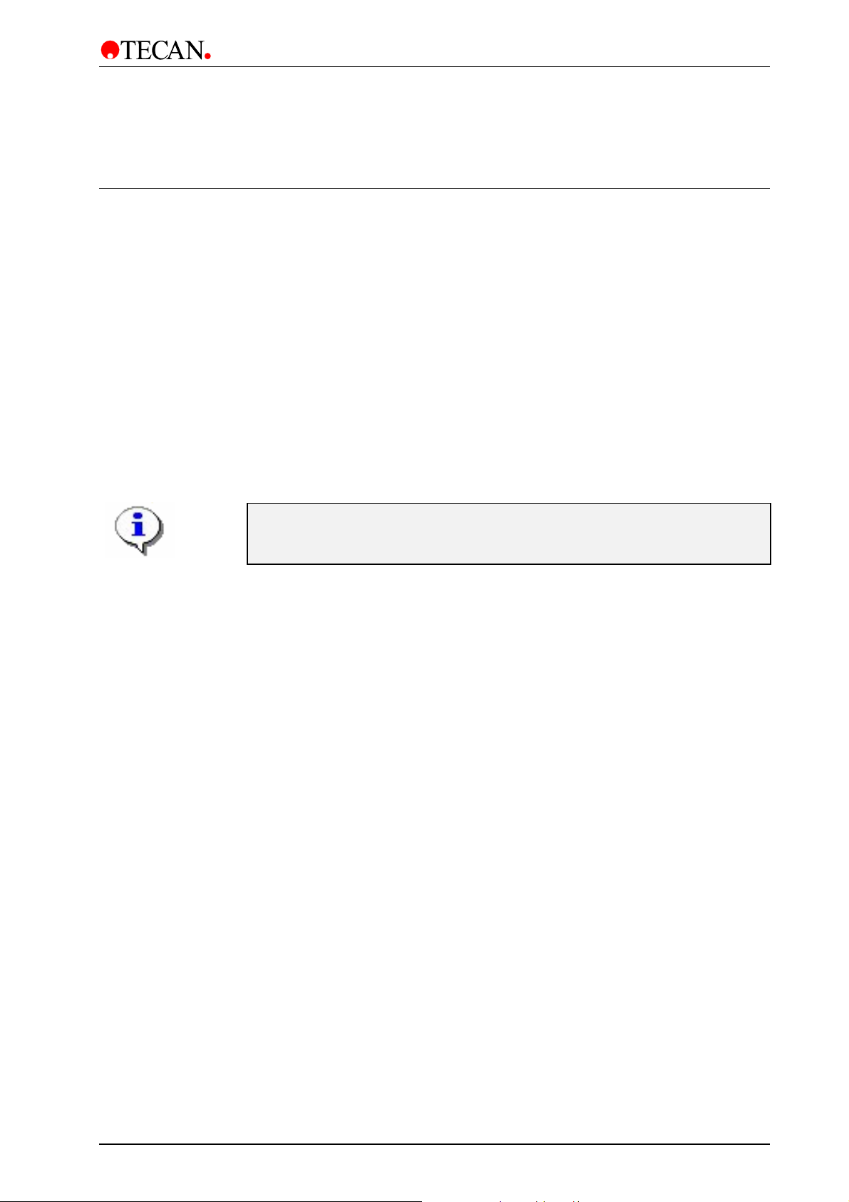
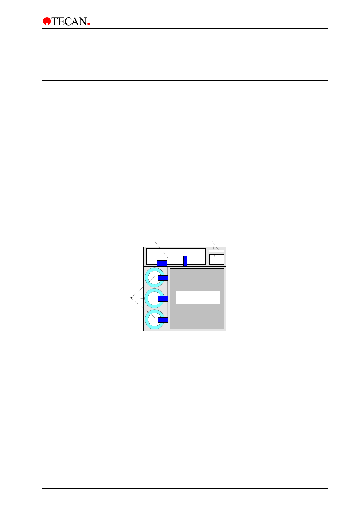
1.2 Instrument Description
The diagram below shows the main components of the instrument:
Manifold Arm
Manifold
POWER
Power ON LED
Keyboa r d an d
Display Unit
Waste Sink
Plate Support
Guide Bar
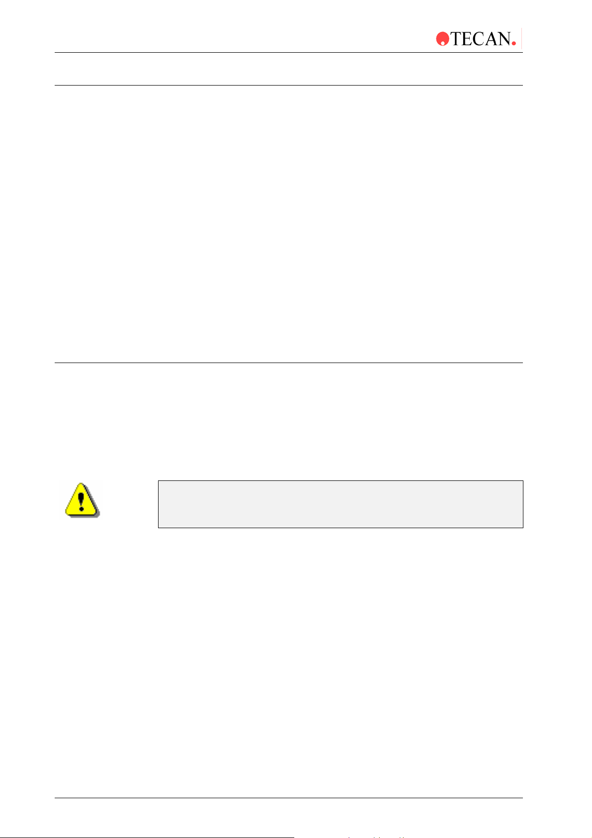
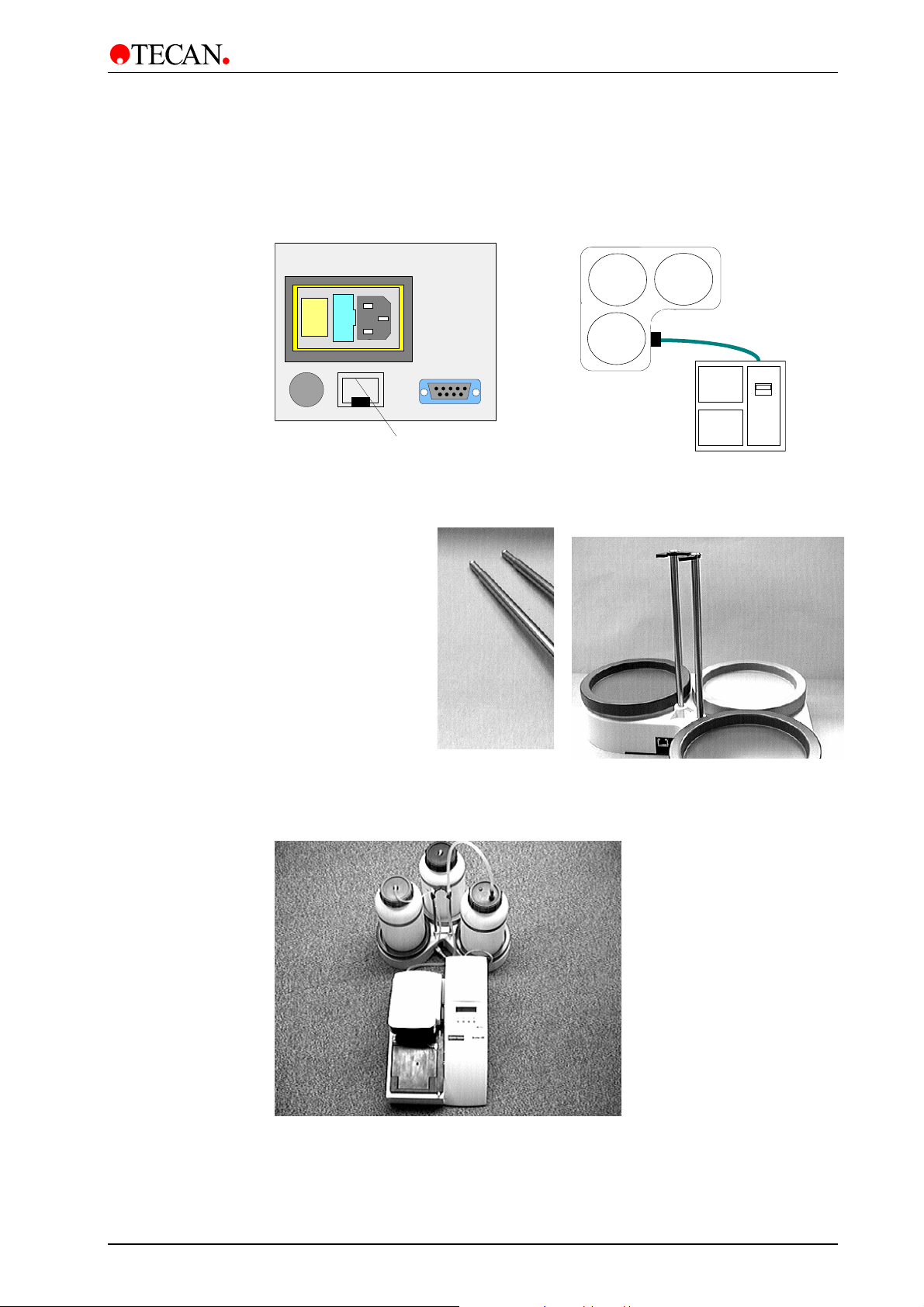
1.2.1 Rear Panel Connections
The instrument has the following connections on the back panel.
Mains Power
Socket
Fuse
Compartment
ON/OFF
Switch
Hand held
Barcode
Reader
Bottle Holder with
Liquid Sensor for
each bottle
Printer Connecto
or
Serial RS 232 fo
Remote Control
Inlets for channels 1 - 4
erosol
Tubing
option
Waste
Tubing
red
1-2 Technical Manual for Columbus Washer No. 30000294 Rev. No. 1.7 2006-02
Page 11
1. General
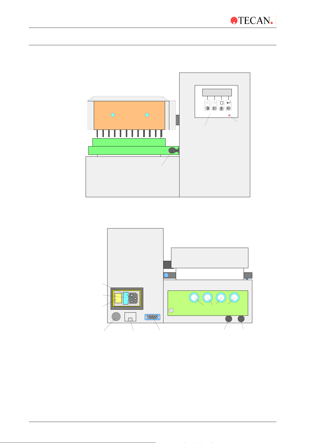
C
A
(Instrument with Pinch Valves)
Mains Power
Socket
Fuse
ompartment
ON/OFF
Switch
Hand held
Barcode
Reader
Bottle Holder with
Liquid Sensor for
each bottle
Prime
valve
Printer Connector
or
Serial RS 232 for
Remote Control
Channel 1
Inlet
Channel 2
Inlet
Channel 3
Inlet
erosol
Tubing
(yellow)
Channel 4
All connected devices must be proved and listed with regulations
EN 60950, UL 1950 or CSA C22.2 No. 950 for Data Processing Devices
Inlet
Waste
Tubing
(red)
2006-02 Technical Manual for Columbus Washer No. 30000294 Rev. No. 1.7 1-3
Page 12
1. General
)
p
g
q
g
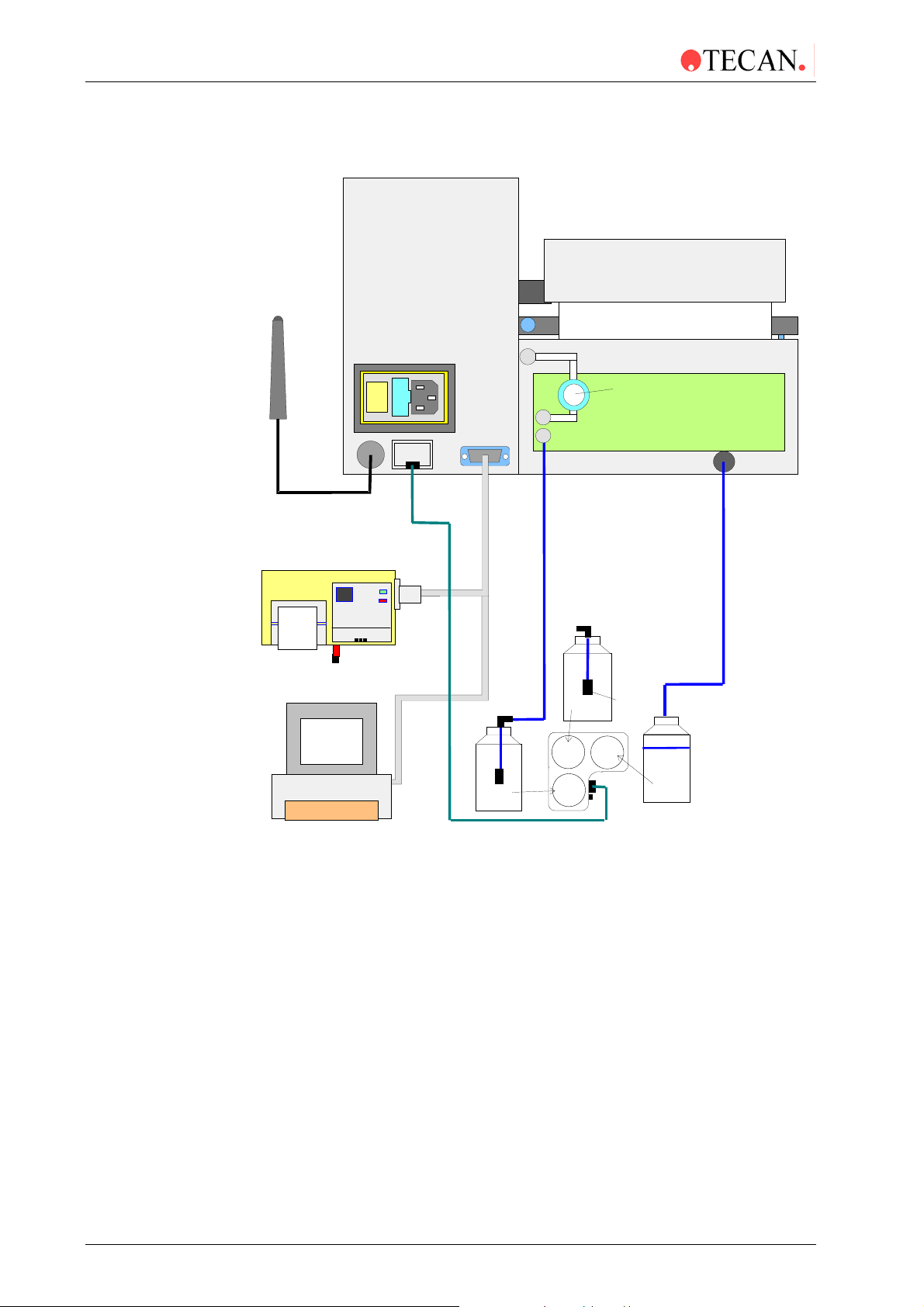
1.2.2 Connection Diagram for Columbus (1 Liquid Channel)*
Hand held
Barcode
Reader (option)
Prime
valve
Printer (option
or
Com
uter for
Remote Control
Marked
reen
grey
Wash
uid
Li
Bottle Holder with liquid
sensor for each bottle
reen
Rinse
solution
red
Inlet
filter
* Some of the instruments may include the prime valve.
Waste
Bottle
Marked
red
1-4 Technical Manual for Columbus Washer No. 30000294 Rev. No. 1.7 2006-02
Page 13
1. General
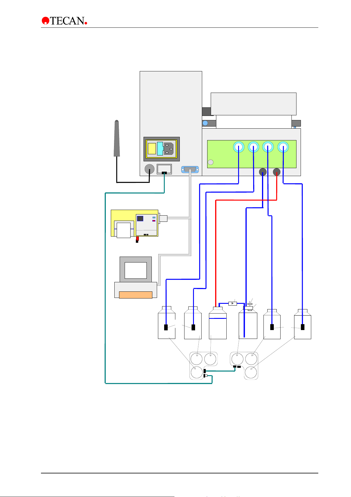
1.2.3 Connection Diagram for Columbus (4 Liquid Channels)*
Hand held Barcode
Reader (option)
Printer (option)
Computer for
Remote Control
Marked green
Inlet
filter
Wash
Liquid 1
Bottle Holders with liquid
sensor for each bottle
or
Marked grey
Rinse
solution
grey red
green
Marked
red
Waste
Bottle
Marked
blue
None Return
Valve
yellow
Marked
yellow
Foam
Bottle
purple
blue
Aerosol
Filter
Seperator
Water
Wash
Liquid 3
Marked
purple
Inlet
filter
Marked
blue
Wash
Liquid 2
* Some of the instruments may include the prime valve.
2006-02 Technical Manual for Columbus Washer No. 30000294 Rev. No. 1.7 1-5
Page 14
1. General
r
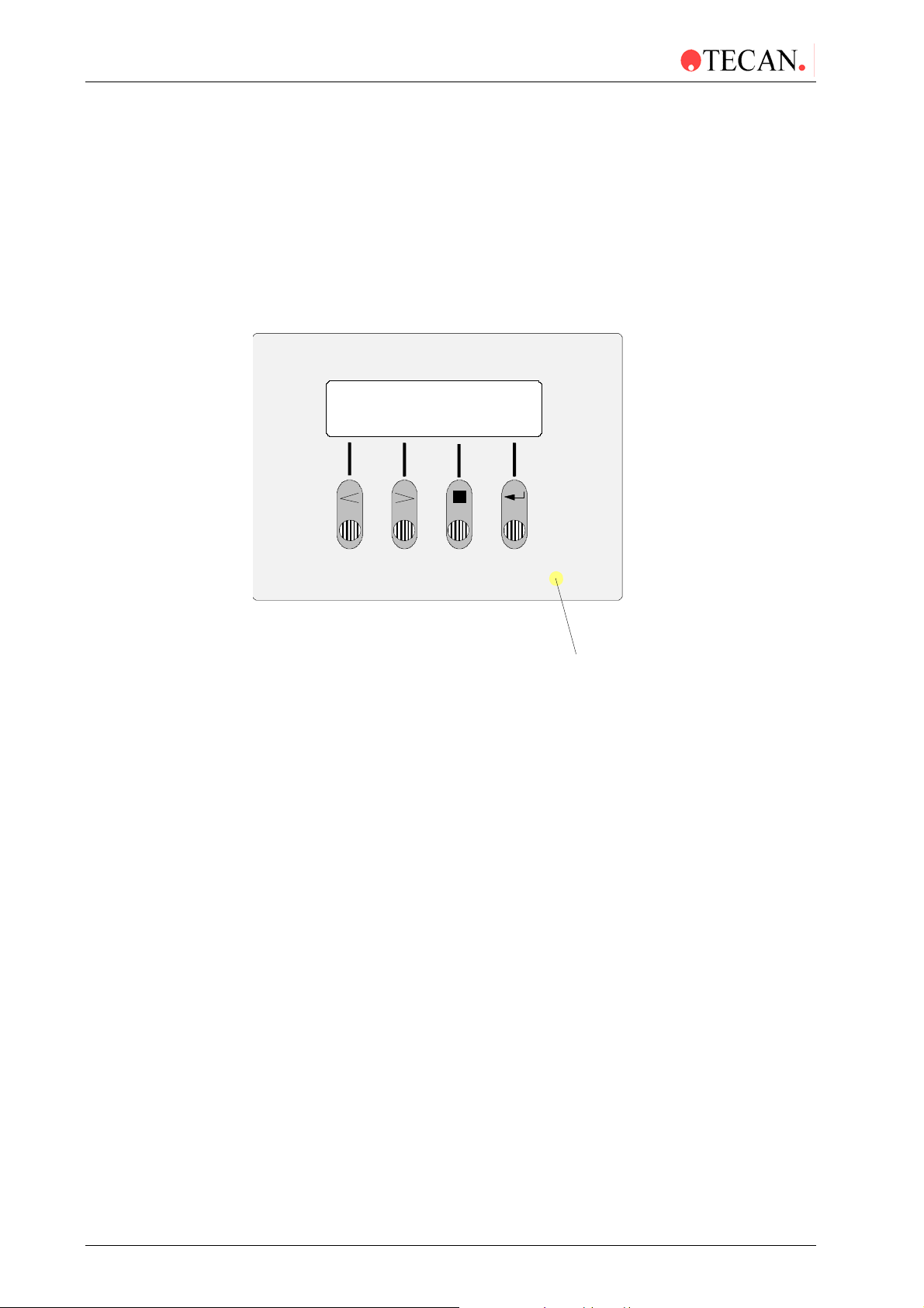
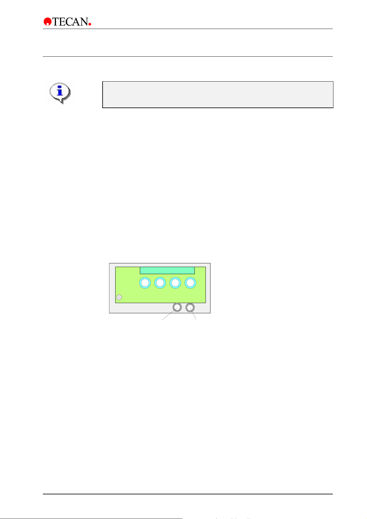
1.2.4 Keyboard and Display Unit
The Washer is operated via a keyboard and a control panel consisting of a two
row, sixteen digit Liquid Crystal Display (LCD) unit.
The top row of the display unit is used for messages and the bottom row for the
key functions or options.
A Light Emitting Diode (LED) in the center of the letter "O" of the word "POWER"
indicates when the Washer is switched ON.
Key 1 Key 2 Key 3
Key 4
POWER
Powe
ON LED
1-6 Technical Manual for Columbus Washer No. 30000294 Rev. No. 1.7 2006-02
Page 15
1. General
A
A
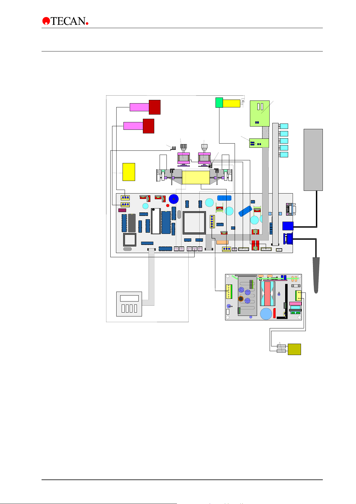
1.3 Interconnection Diagram
The diagram below shows how the various parts of the instrument are
interconnected.
Dispensing Pump
spirating Pump
erosol Pump
Prime Valve
Plate Home Position
Optical Switch
Plate Transport
Motor
Manifold Arm
Orbital Shaking
Motor
*
Motor
Home Position
Optical Switch
Manifold Typeand
Plate MismatchBoard
Fill Verify and
Plate Mismatch
Board
Solenoid 4
Solenoid 3
Solenoid 2
Solenoid 1
Dispense
Solenoid
Liquid
Detection
System
Keyboard /
Display Unit
Printer / Serial
Connector
EEPROM
CPU
Barcode Reader
Power Supply Board
Fuses
Mains Input
ON/OFF Switch
* The Orbital Shaking option is not used.
2006-02 Technical Manual for Columbus Washer No. 30000294 Rev. No. 1.7 1-7
Page 16

Page 17
2. Installation Procedure
(op
)
A
p
2. Installation Procedure
2.1 Unpacking and Inspection
The instrument is shipped in one carton, which contains:
• Instrument
• Accessory package which contains:
Spare manifold cover with two screws and Allen key
Operating manual
Mains power cable
Cleaning needles
2 spare fuses
Solution tube
3 spare 0 – ring seals for manifold
• Bottle set containing:
3 x 2.5 l bottles for the standard instrument
Liquid Sensor System
tional
Bottles
ccessory package
and o
erating manual
Instrument
2006-02 Technical Manual for Columbus Washer No. 30000294 Rev. No. 1.7 2-1
Page 18
2. Installation Procedure
2.2 Unpacking Procedure
1. Visually inspect the container for damage before it is opened.
Report any damage immediately.
2. To place the instrument, select a location that is flat, level, vibration free,
away from direct sunlight, and free from dust, solvents and acid vapors.
Allow 10 cm distance between the back of the instrument and the wall or any
other equipment.
3. Place the carton in an upright position and open it.
4. Lift the instrument out of the carton and place it in the selected location.
5. Visually inspect the instrument for loose, bent or broken parts.
Report any damage immediately.
6. Compare the serial number on the rear panel of the instrument with the
serial number on the packing slip.
Report any discrepancy immediately.
7. Check the instrument accessories against the packing list.
8. Save packing materials for future use.
2.3 Power Requirements
The instrument is designed to operate at either 100 - 120 volt or 220 - 240 volt.
No voltage setting is required as the washer automatically senses the supplied
voltage.
The washer requires 2 x T 1.6 A / 250 V (slow blow) fuses.
WARNING
TO PREVENT THE RISK OF FIRE, THE MAINS FUSES SHOULD ONLY BE
REPLACED WITH THE SAME TYPE AND RATING OF FUSE.
2-2 Technical Manual for Columbus Washer No. 30000294 Rev. No. 1.7 2006-02
Page 19
2. Installation Procedure
A
2.4 Installation Procedure
Before the instrument is installed and switched on, it should be left to stand
for at least three hours, so there is no possibility of condensation causing a
2.4.1 Installing the Instrument
• Unpack the instrument and check the contents.
See 2.2 Unpacking Procedure.
• Connect the solution tubes to the inlet connectors.
See 2.4.3 Connecting the Solution Tubes.
• Setup possible instrument options. See page 2 – 5 and 2 – 6.
• Connect instrument to the power supply. See 2.4.7 Power Connections.
• Define the plate parameters in the Adjust menu. See chapter 3.
short circuit.
• Program the wash procedure. See chapter 3.
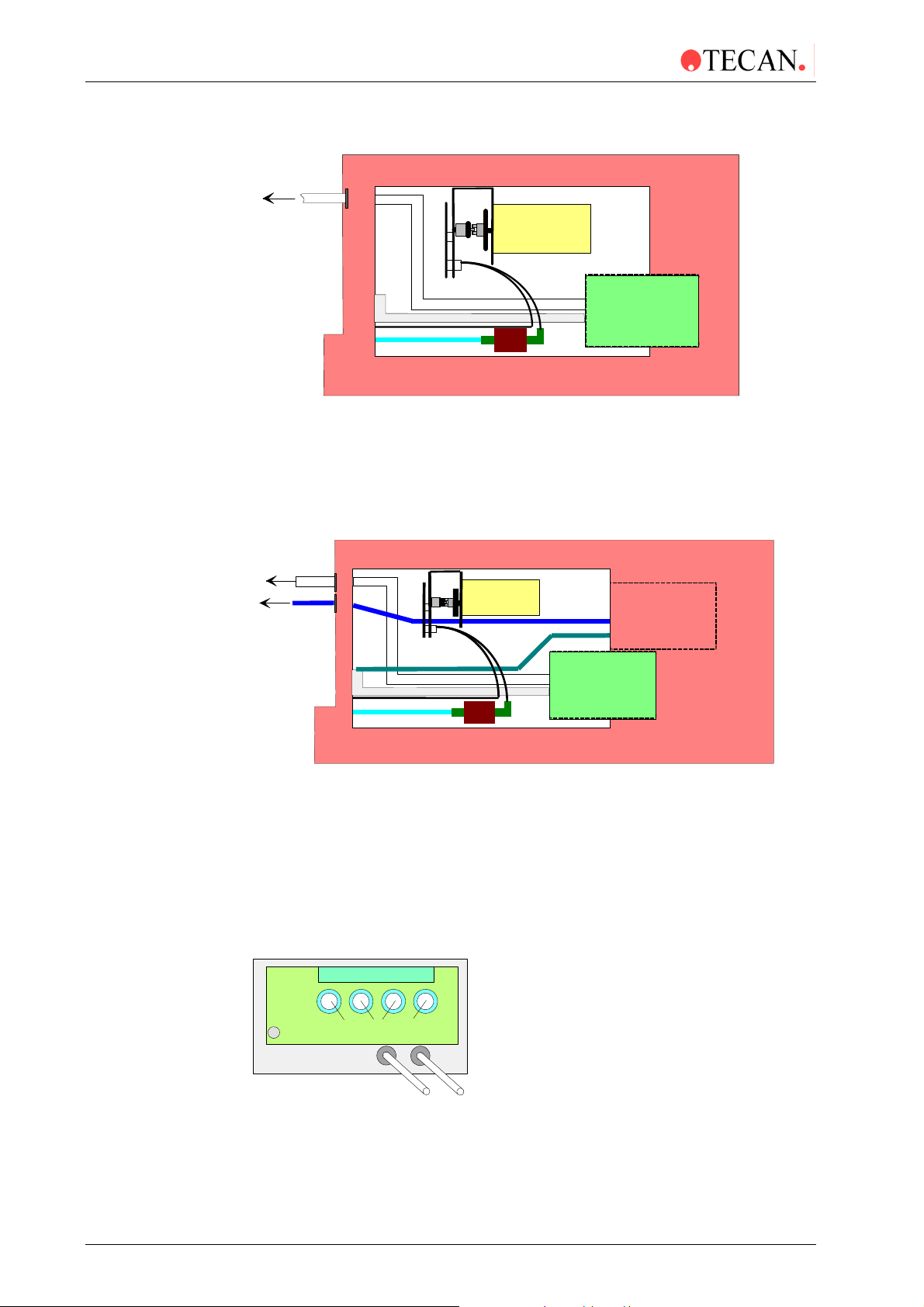
2.4.2 Connecting the Waste Tubing
Turn the instrument onto the right hand side.
Slide the waste tube through the hole in the back panel.
erosol Tube Hole
(optional)
Connect the waste tube onto the top connector of the aspirating pump.
Waste Tube Hole
2006-02 Technical Manual for Columbus Washer No. 30000294 Rev. No. 1.7 2-3
Page 20
2. Installation Procedure
A
A
A
A
A
Standard Instrument
Waste Bottle
Dispensing
Pump
Waste Tube
spirating Tube to
Solution Tubes to Manifold
Aspirating Pump
Turn the instrument back to the normal position.
Place the other end of the waste tubing into the waste bottle.
Connect the aerosol tube onto the aerosol pump if this option is fitted. This is not
necessary for the standard instrument.
Instrument with Aerosol Protection Option
Waste Bottle
Dispensing Pump
erosol Bottle
Aspirating Tube to Manifold
Solution Tubes to Manifold
spirating Pump
erosol
Pump
Turn the instrument back to the normal position.
Place the other end of the aerosol tubing into the aerosol bottle.
2.4.3 Connecting the Solution Tubes
The solution tubes are connected onto the inlet connectors on the back panel of
the instrument. The instrument is supplied with four meters of tubing that can be
cut to the required length (maximum 1 meter).
Inlets for channe ls 1 - 4
erosol Tube*
(optional)
Waste Tube
red
2-4 Technical Manual for Columbus Washer No. 30000294 Rev. No. 1.7 2006-02
Page 21
2. Installation Procedure
2.4.4 Fitting and Connecting the Liquid Sensors (Optional)
Connect the detector unit cable into the appropriate socket in the back panel of
the instrument. The liquid sensor system can be extended to control up to four
different liquid bottles and one waste bottle.
rinse
grey
liquid 1
green
Liquid Sensor
Fix the tube support in the bottle holder as shown below.
Tube support
waste
red
Insert the tubes and connect the bottle holder to the instrument.
2006-02 Technical Manual for Columbus Washer No. 30000294 Rev. No. 1.7 2-5
Page 22
2. Installation Procedure
2.4.5 Connecting the Barcode Reader (Optional)
Before the barcode reader can be connected to the instrument, the supplied
barcode chips must be added to the main board. For more details contact your
service technician.
Hand Held Barcode
Reader
Liquid Sensor
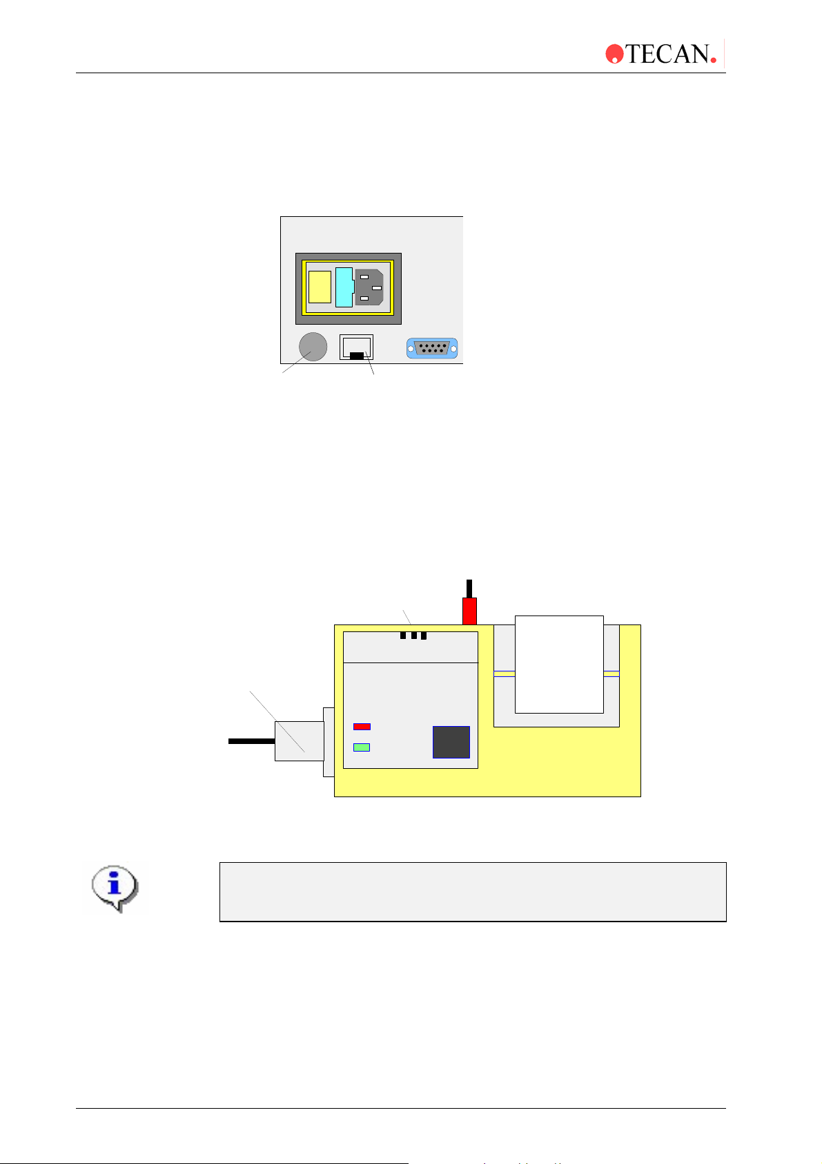
2.4.6 Connecting the Printer (Optional)
Before the printer can be connected to the instrument, the supplied chip must be
added to the main board. For more details contact your service technician.
Connect the printer to the instrument using the supplied cable.
Connect the power supply cable to the printer.
ON /OFF
Switch
OFF 1 2
POWER
Connection Cable
BATT. LOW
POWER
ON
PAPER
FEED
Power Cable
2.4.7 Power Connections
Before the instrument is installed and switched on, it should be left to
stand for at least three hours, so there is no possibility of condensation
Ensure that the on / off switch in the back panel of the instrument is in the off
position.
Insert the mains power cable into the mains power socket on the rear of the
instrument.
2-6 Technical Manual for Columbus Washer No. 30000294 Rev. No. 1.7 2006-02
causing a short circuit.
Page 23

3. Firmware and Software Description
3. Firmware and Software
Description
3.1 Instrument Software Features
The instrument has the following software features:
• 30 user definable washing programs, permanently stored under the
numbers 1 to 30.
• Up to 60 processing steps per program, each processing step can be
identical or different from the previous step.
• 3 washing modes, normal washing, bottom washing and overflow washing.
Set by the Plate Type parameters.
• Soak time. selectable from 1 to 999 seconds.
• Software selectable dispensing speeds
• Software selectable aspirating speeds
• Software selectable bottom position, for aspiration contact to the bottom
of the wells.
• 4 rinse modes, the different rinse modes can be used to select how the
instrument is rinsed before it is left to stand or switched OFF.
• Automatic microplate centering, the microplate is automatically centered
before the start of the washing program.
• Programmable strip selection, the program can be defined so that the
strips to be washed can be selected before starting the washing procedure.
2006-02 Technical Manual for Columbus Washer No. 30000294 Rev. No. 1.7 3-1
Page 24
3. Firmware and Software Description
3.2 Onboard Software Menus
The instrument can be used in the following onboard software menus.
3.2.1 Run
Selection of the run procedure to perform the selected program.
3.2.2 Prime
Before the instrument can be used, all dispensing channels must be primed
with the required solution.
Ensure that the bottle of priming solution is always full at the beginning of
the priming procedure and check that the inlet filters in the liquid tubes are
clear.
Please ensure that the dispensing and aspiration pumps are not run for
longer than a few minutes without liquid or they will be damaged.
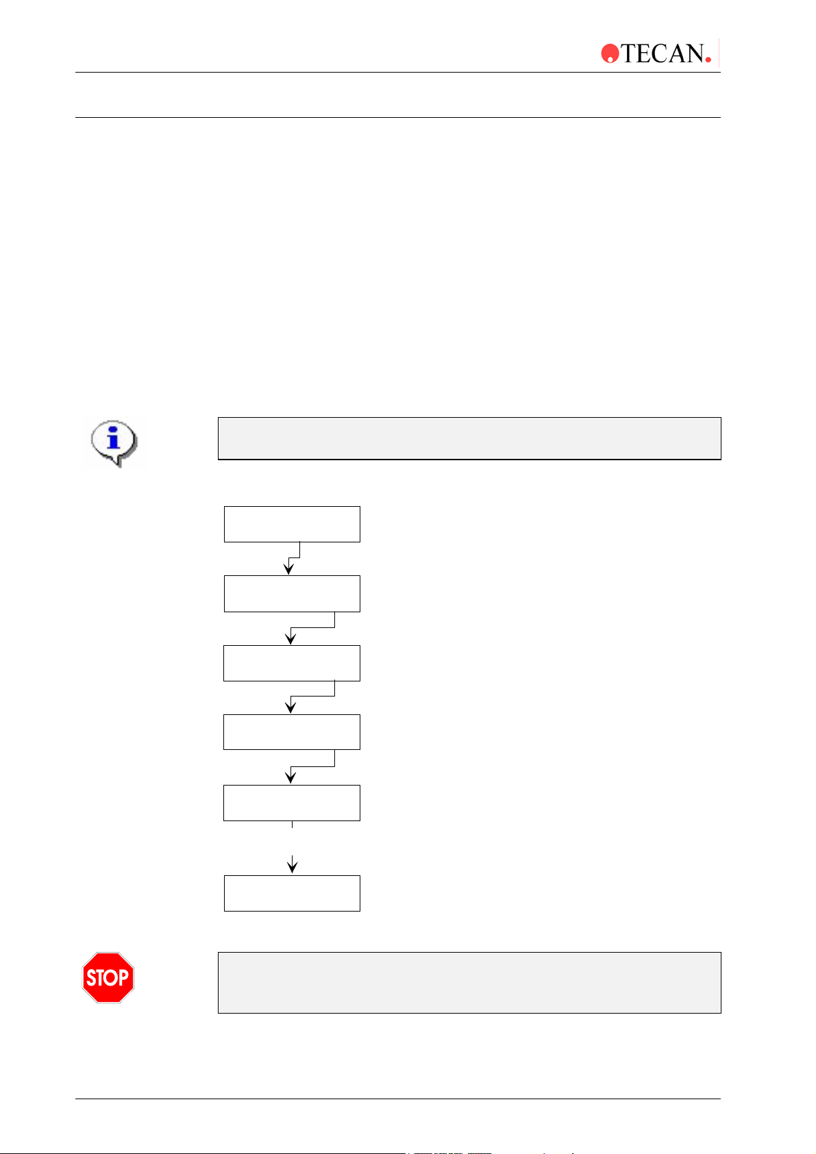
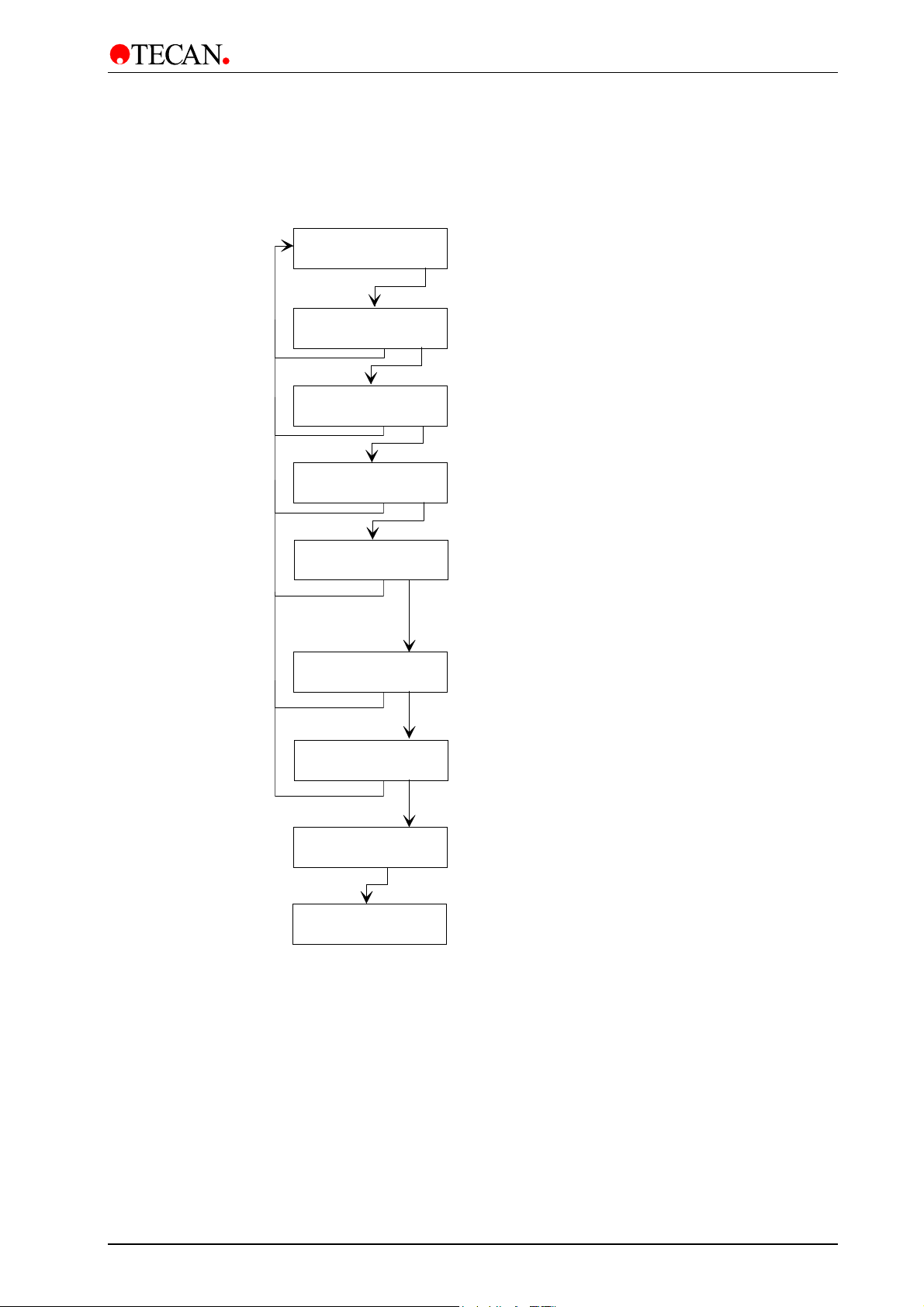
The priming procedure is performed using the following procedure:
Run XX yyyyyyyy
- + other yes
Prime Ch1
- + other yes
Prime Solution ?
exit yes
Waste Bottle OK?
exit yes
Prime ChX Y sec
Stop
Priming Procedure
performed
Run XX yyyyyyyy
- + other yes
Select required channel to be primed
Required solution in bottle and inlet
tube inserted into solution
Waste bottle empty
Priming procedure being performed
Instrument ready to wash microplate
Caution
Do not use the instrument to aspirate or dispense any acidic solutions as
3-2 Technical Manual for Columbus Washer No. 30000294 Rev. No. 1.7 2006-02
this could damage the instrument.
Page 25

3. Firmware and Software Description
y
y
y
y
g
p
yyyyyyy
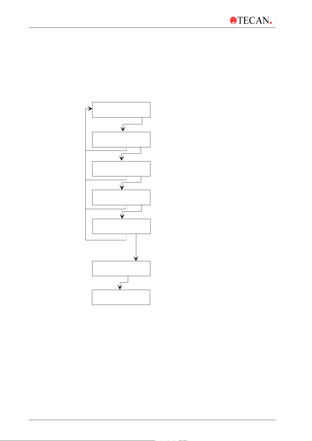
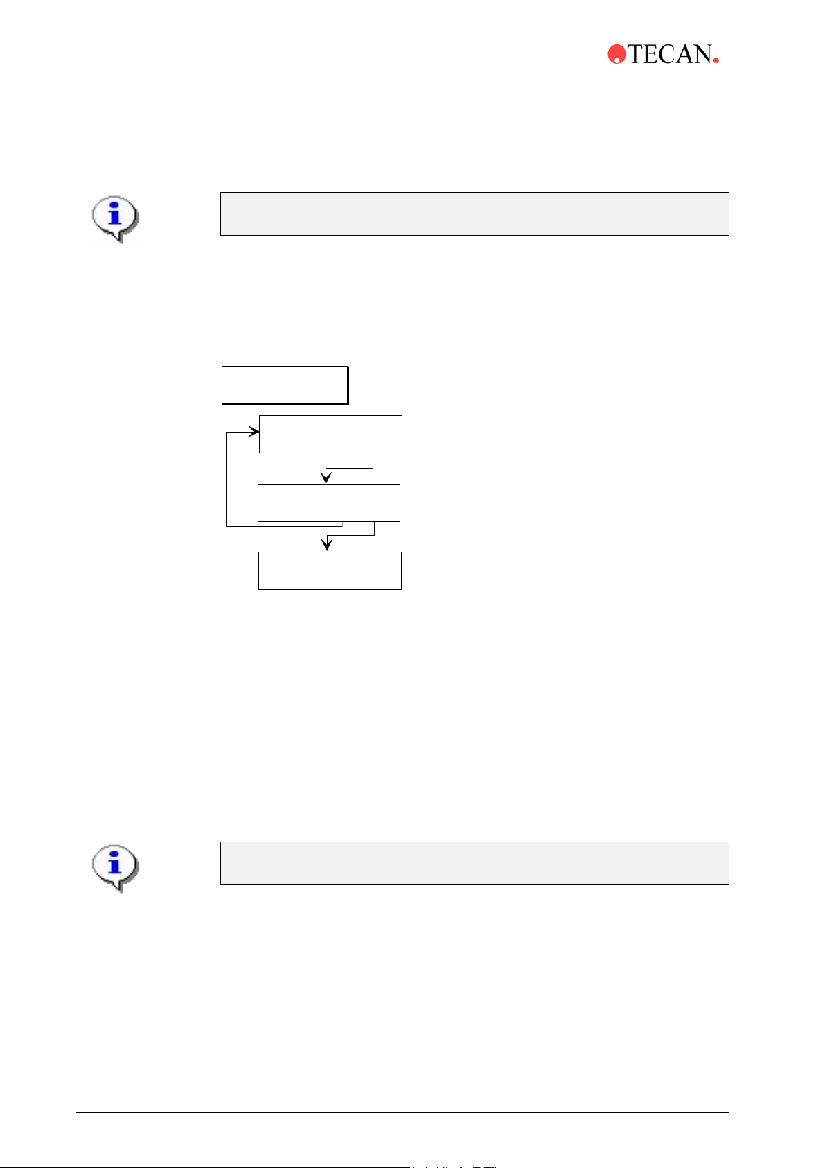
3.2.3 Rinse
There are four Rinse modes to flush the liquid system and prevent needle
blockages. They should be carried out when the instrument is left to stand or is
switched off at the end of working.
The Rinse modes are:
Rinse Soak
Rinse Day
Rinse Night
Rinse Auto
Rinse: Soak
This procedure is used if the instrument is to be left to stand for a short time.
(1/2 hr. or less).
With this procedure you can use either distilled water or wash solution.
Rinse: Soak
- + other
Soak: CH1
- + exit
Rinse Solution ?
exit
Waste Bottle OK?
exit
Soakin
Sto
Run XX:
- + other yes
es
es
es
es
Select and confirm Soak Rinse procedure
Select required channel (1 - 4)
Confirm that the rinsing solution
and the tube are in the bottle
Confirm waste bottle is empty
The waste sink is filled with solution
and the manifold is lowered into it
Manifold left in solution until Stop key pressed
Standby mode
Washing procedure can be performed
2006-02 Technical Manual for Columbus Washer No. 30000294 Rev. No. 1.7 3-3
Page 26
3. Firmware and Software Description
Rinse: Day
This procedure is used to rinse the wash solution system if the instrument is to be
left standing for a longer time. Alternatively it can be used to rinse the wash
solution system after the instrument has been left for a long time.
With this procedure you can use either distilled water or wash solution.
If the instrument is left to stand for 1 hr to 1/2 day, wash solution can be used, for
longer times use distilled water.
Rinse: Day
- + other yes
Day: CH1
- + exit yes
Rinse Solution ?
exit yes
Waste Bottle OK?
exit yes
Rinse ChX YY sec
Stop
Select and confirm Day Rinse procedure
Select required channel (1 - 4)
Confirm rinsing solution and tube in bottle
Confirm waste bottle is empty
Wash system rinsed for set rinse time
The waste sink is filled with solution and
the manifold is lowered into it
Soaking
Stop
Run XX:yyyyyyy
- + other yes
Manifold left in solution until
key pressed
Stop
Standby mode
Washing Procedure can be performed
3-4 Technical Manual for Columbus Washer No. 30000294 Rev. No. 1.7 2006-02
Page 27
Rinse: Night
y
g
y
y
y
p
p
g
p
yyyyyyy
p
3. Firmware and Software Description
This procedure is used to thoroughly rinse the wash solution system and leave
the manifold soaking in the waste sink full of solution at the end of working. This
procedure requires distilled water.
Rinse: Night
- + other
ht: CH1
Ni
- + exit
Rinse Solution ?
exit
Waste Bottle OK?
exit
Rinse ChX YY sec
Sto
Soaking xx sec
Sto
es
es
es
es
Select and confirm Night Rinse procedure
Select required channel (1 - 4 or ALL)
Confirm rinsing solution and tube in bottle
Confirm waste bottle is empty
Wash system rinsed for set rinse time
The waste sink is filled with the distilled
water and the manifold is lowered into it
Manifold left in solution for set soak time (1 min)
Rinse: Auto
Rinse ChX YY sec
Sto
Soakin
Sto
Run XX:
- + other yes
Wash system rinsed for set rinse time
The waste sink is filled with the distilled water
and the manifold is lowered into it.
Manifold left in solution until Stop key pressed
Standby mode
Washing procedure can be performed
This procedure is the same as the Rinse: Day procedure, except that the rinsing
procedure is automatically repeated after a set repeat time. The repeat time can
be set in the Adjust menu between 1 and 24 hrs.
2006-02 Technical Manual for Columbus Washer No. 30000294 Rev. No. 1.7 3-5
Page 28
3. Firmware and Software Description
3.2.4 Program
Selection of the programming procedure, to define the required program.
For more information about the programming procedure, see chapter 4 in
the Columbus Operating Manual.
3.2.5 Clear
This submenu is used to clear a program from the instrument's memory. If the
program is locked it can not be cleared and the following error message is
displayed:
Program locked
yes
The function Clear ALL is available within the Clear Program option. This
function enables you to clear all of the programs (excluding those that are
locked!). The Clear ALL function is found before program 1 and after program
30. Use the cursor keys to skip through the programs and once Clear ALL is
displayed press yes and all of the programs (with the exception of those that are
locked) will be cleared.
This option is not to be confused with the Clear ALL function in the Service
menu.
3.2.6 Show
Procedure to show the parameters for a program.
Clear XX:yyyyyyy
- + other yes
Clear XX:yyyyyyy
no yes
Clear XX:yyyyyyy
- + other yes
Select required program to be
cleared from instrument's memory
Confirm that selected program is
to be cleared
Select next program to be cleared or
required option in Mode Selection menu
For more information about the Show procedure, see Columbus Operating
Manual.
3-6 Technical Manual for Columbus Washer No. 30000294 Rev. No. 1.7 2006-02
Page 29

3. Firmware and Software Description
3.2.7 Adjust
The Adjust menu has the following options:
Plate Type
Prime Time
Rinse Time
Autorinse
Kit Select
Date
Time
Sel. Manifold
Adj. Liq. Sensor
Exit Adjust
Entering the Adjust Menu
When the instrument is in the standby mode and the following message is
displayed:
Run XX yyyyyyyy
- + other yes
Adjustment procedure for setting the parameters for up
to nine different types of microplates
Adjust the time that the Priming procedure is performed
for.
Adjust the time that the Rinsing procedure is performed
for.
Adjust the time between the Autorinse cycles.
This option is not available in this instrument.
Set the date
Set the time
Set the manifold that is fitted to the instrument
The switch thresholds for the wash, rinse and waste
liquid can be defined.
Exit from the Adjust menu.
To select the Adjust menu, press other u ntil the following message is displayed:
Adjust Menu
other yes
Select yes to enter the Adjust menu and then the various options in the Adjust
menu can now be selected using other.
When the required option is displayed, press yes to enter the parameter setting
procedure.
2006-02 Technical Manual for Columbus Washer No. 30000294 Rev. No. 1.7 3-7
Page 30
3. Firmware and Software Description
A
A
Adjust Menu
other yes
Platetype: 1
- + other yes
Primetime:10 sec
- + other yes
Rinsetime: 10sec
- + other yes
AutoRinse: 1 h
- + other yes
Kit Select: Off
- + other yes
Confirm selection of Adjust Menu
Plate Type definition menu
Use '-' and '+' keys to select required p latet ype
Plate Type definition procedure
Priming Time setting
Use '-' and '+' keys to select required priming time
(5 - 99 sec.)*
Rinse Time setting
Use '-' and '+' key s to select required rinsing time
(5 - 99 sec.)*
utomatic Rinsing Time setting
Use '-' and '+' keys to select required tim e between
utomatic Rinsing procedures (1 - 24 hrs.)
This option is not available in this instrument
Date: ddmmmyyyy
d m other y
Time: hh:mm xx
h m other form
Sel.Manifold: xx
- + other yes
Adj.Liq.Sens.:
other yes
Date Setting
Use 'd' key to change day setting
Use 'm' key to chang month setting
Use 'y' key to change year setting
Time Setting
Use 'h' key to change hour setting
Use 'm' key to chang minute setting
Use 'Form ' key to change from 12 to 24 hrs format
Manifold setting
Use '-' and '+' keys to select fitted manifold . (8, 12, 16)
If Manifold detect option fitted, this setting is used
as the default when programming
Liquid Detection Sensor setting
Exit Adjust
other yes
Exit Adjust Menu
* Instruments that have the prime valve have a priming time of 8 - 99 seconds.
3-8 Technical Manual for Columbus Washer No. 30000294 Rev. No. 1.7 2006-02
Page 31

3. Firmware and Software Description
Adjust Plate Type
This option is used to set the following parameters for the different types of
microplates. The default is a 96 well Greiner microplate.
The following parameters are set:
Parameters Options
Plate type number
Bottom Form
Dispensing Position
Aspirate Position
Aspirate Position 2
Bottom Position
Bottom Wash Position
Overflow Wash
Position
Before starting the adjustment procedure, insert the microplate to be
adapted into the plate support.
1 - 9
Set whether the microplate has flat or round
bottom wells.
Set the position in the wells where the solution
will be dispensed.
Set the position in the wells where the solution
will be aspirated.
Set the position in the wells for the crosswise
aspiration procedure. (flat bottom wells only)
Set the position of the aspirating needles for the
bottom of the well.
Set the position of the aspirating needles for the
bottom washing procedure.
Set the position of the aspirating needles for the
overflow washing procedure.
2006-02 Technical Manual for Columbus Washer No. 30000294 Rev. No. 1.7 3-9
Page 32

3. Firmware and Software Description
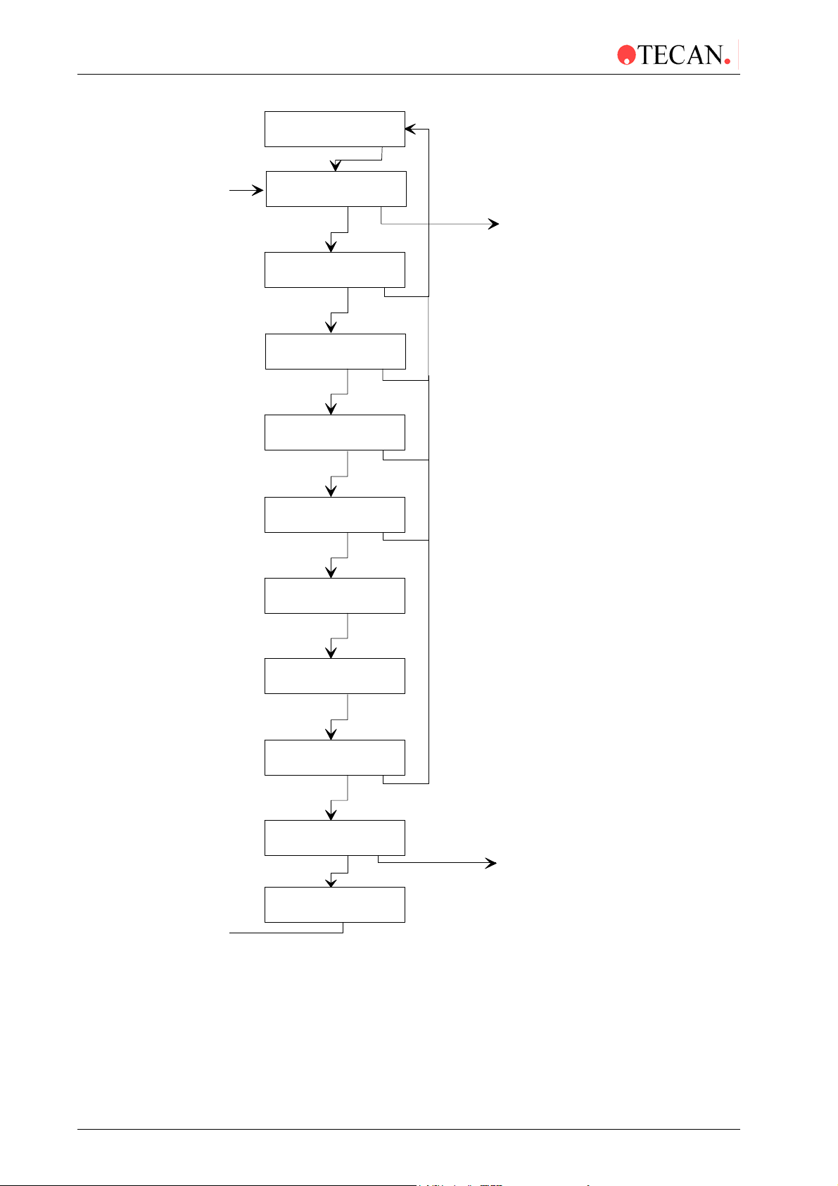
Round Bottom Plates
Adjust Menu
other yes
Plate: X
- + other yes
Plate: X
890 , , ABCDE
Bottomform Round
- + exit yes
Disp.Pos XXX
- + exit yes
Asp.Pos XXX
- + exit yes
Confirm selection of Adjust menu
Plate Type definition menu
Use '-' and '+' keys to select required platetype (1 - 9)
Enter the required name for the plate
(up to 8 characters). 1,2,3,4,5,6,7,8,9,0 & A-Z
To enter a name use the ‘<’ and ‘>’ keys to place a character
between the commas. Confirm the selection with the ‘↵’ key.
To delete the last character use the ‘ ’ sign.
When the name is complete, confirm with the ‘↵’ key.
Plate Bottom Form setting
Use '-' and '+' keys to select required bottom form
(flat or round)
Set Dispensing position
Use '-' and '+' keys to move the plate support so
that the dispensing needles are in the correct position
Set Aspirating position
Use '-' and '+' keys to move the plate support so
that the aspirating needles are in the correct position
Asp.Pos Botm XXX
- + exit yes
Washpos Botm XXX
- + exit yes
Washpos Ovfl XXX
- + exit yes
Platetype: X
- + other yes
Use '-' and '+' keys to move the manifold so that the
aspirating needles are in the correct position for
aspirating the bottom of the wells
Set Bottom Washing position
Use '-' and '+' keys to move the manifold so that the
aspirating needles are in the correct position for
the Bottom Washing procedure
Set Overflow Washing position
Use '-' and '+' keys to move the manifold so that the
aspirating needles are in the correct position for
the Overflow Washing procedure
Select plate type to be defined
Set Bottom Aspirating position
3-10 Technical Manual for Columbus Washer No. 30000294 Rev. No. 1.7 2006-02
Page 33

3. Firmware and Software Description
Flat Bottom Plates
Adjust Menu
other yes
Plate: X
- + other yes
Plate: X
890 , , ABCDE
Bottomform Flat
- + exit yes
Disp.Pos XXX
- + exit yes
Asp.Pos 1 XXX
- + exit yes
Confirm selection of Adjust menu
Plate Type definition menu
Use '-' and '+' keys to select required platetype (1 - 9)
Enter the required name for the plate
(up to 8 characters). 1,2,3,4,5,6,7,8,9,0 & A-Z
To enter a name use the ‘<’ and ‘>’ keys to place a character
between the commas. Confirm the selection with the ‘↵’ key.
To delete the last character use the ‘ ’ sign.
When the name is complete, confirm with the ‘↵ ’ key.
Plate Bottom Form setting
Use '-' and '+' keys to select required bottom form
(flat or round)
Set Dispensing position
Use '-' and '+' keys to move the plate support so
that the dispensing needles are in the correct position
Set Aspirating position 1
Use '-' and '+' keys to move the plate support so
that the aspirating needles are in the correct position
Asp.Pos 2 XXX
- + exit yes
Asp.Pos Botm XXX
- + exit yes
Washpos Botm XXX
- + exit yes
Washpos Ovfl XXX
- + exit yes
Platetype: X
- + other yes
Set Aspirating position 2
Use '-' and '+' keys to move the plate support so
that the aspirating needles are in the correct position
Set Bottom Aspirating position
Use '-' and '+' keys to move the manifold so that the
aspirating needles are in the correct position for
aspirating the bottom of the wells
Set Bottom Washing position
Use '-' and '+' keys to move the manifold so that the
aspirating needles are in the correct position for
the Bottom Washing procedure
Set Overflow Washing position
Use '-' and '+' keys to move the manifold so that the
aspirating needles are in the correct position for
the Overflow Washing procedure
Select Plate type to be defined
2006-02 Technical Manual for Columbus Washer No. 30000294 Rev. No. 1.7 3-11
Page 34
3. Firmware and Software Description
To enter the Plate type option, press other until the following message is
displayed:
Plate: XXXXX
- + other yes
Where X is the displayed plate type number and plate name.
Use the - and + keys to select the required plate type number that is to be
defined. (1 - 9).
Pressing - decreases the displayed plate type.
Pressing + increases the displayed plate type.
When the required plate type is displayed press yes and the following message is
displayed:
Bottomform Flat
- + exit yes
Use the - and + keys to select the required bottom form of the wells. (flat or
round).
When the required bottom form is displayed press yes to confirm the selection.
Flat Bottom Wells
The following procedure is used when a microplate with flat bottom wells is to be
defined.
After yes has been pressed to confirm the selection of flat bottom wells, the
instrument initializes the motors and moves the microplate under the manifold.
When the microplate is under the manifold, the following message is displayed:
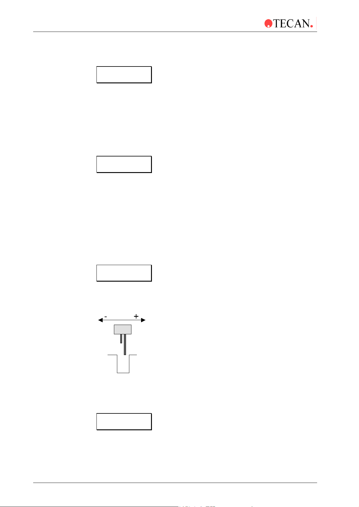
Disp-Pos: XXX
+ exit yes
Where XXX is the displayed number of steps.
Use the - and + keys to move the microplate until the dispensing needles are in
the correct position.
Pressing the - and + keys moves the microplate forwards and backwards so that
the dispensing needles are positioned further back/forward in the wells.
When the dispensing needles are in the correct position, press yes and the
following message is displayed:
Asp.Pos 1 XXX
- + exit yes
3-12 Technical Manual for Columbus Washer No. 30000294 Rev. No. 1.7 2006-02
Page 35

3. Firmware and Software Description
Use the - and + keys to move the microplate until the aspirating needles are in
the correct position for aspirating the side of the well.
Pressing the - and + keys moves the microplate forwards and backwards so that
the aspirating needles are positioned further back/forward in the wells.
When the aspirating needles are in the correct position, press yes and the
following message is displayed:
Asp.Pos 2 XXX
- + exit yes
Use the - and + keys to move the microplate until the aspirating needles are in
the correct position for aspirating the side of the well. (crosswise aspiration)
Pressing the - and + keys moves the microplate forwards and backwards so that
the aspirating needles are positioned further back/forward in the wells.
When the aspirating needles are in the correct position press yes and the
following message is displayed:
Pos Botm XXX
Asp.
- + exit yes
Use the - and + keys to move the manifold until the aspirating needles are in the
correct position for aspirating the bottom of the well.
Pressing the - and + keys move the manifold up and down so that the aspirating
needles are positioned higher/lower in the wells.
When the aspirating needles are in the correct position, press yes and the
following message is displayed:
Washpos Botm XXX
- + exit yes
2006-02 Technical Manual for Columbus Washer No. 30000294 Rev. No. 1.7 3-13
Page 36

3. Firmware and Software Description
Use the - and + keys to move the manifold until the aspirating needles are in the
correct position for aspirating the solution in the bottom washing position.
Pressing the - and + keys moves the manifold up and down so that the aspirating
needles are positioned higher/lower in the wells.
When the aspirating needles are in the correct position, press yes and the
following message is displayed:
Washpos Ovfl XXX
- + exit yes
Use the - and + keys to move the manifold until the aspirating needles are in the
correct position for aspirating the solution in the overflow washing position.
Pressing the - and + keys move the manifold up and down so that the aspirating
needles are positioned higher/lower in the wells.
When the aspirating needles are in the correct position, press yes and the
following message is displayed:
Platetype: X
- + other yes
The parameters for the next plate type can be defined or press other for the next
option in the Adjust menu.
3-14 Technical Manual for Columbus Washer No. 30000294 Rev. No. 1.7 2006-02
Page 37

3. Firmware and Software Description
Round Bottom Wells
The following procedure is used when a microplate with round bottom well s is to
be defined.
After yes has been pressed to confirm the selection of round bottom wells, the
instrument initializes the motors and moves the microplate under the manifold.
When the microplate is under the manifold, the following message is displayed:
Disp.Pos XXX
- + exit yes
Where XXX is the displayed number of steps.
Use the - and + keys to move the microplate until the dispensing needles are in
the correct position.
Pressing the - and + keys moves the microplate forwards and backwards so that
the dispensing needles are positioned further back/forward in the wells.
When the dispensing needles are in the correct position, press yes and the
following message is displayed:
Asp.Pos XXX
- + exit yes
Use the - and + keys to move the microplate until the aspirating needles are in
the correct position for aspirating the middle of the well.
Pressing the - and + keys moves the microplate forwards and backwards so that
the aspirating needles are positioned further back/forward in the wells.
When the aspirating needles are in the correct position, press yes and the
following message is displayed:
Asp.Pos Botm XXX
- + exit yes
2006-02 Technical Manual for Columbus Washer No. 30000294 Rev. No. 1.7 3-15
Page 38

3. Firmware and Software Description
Use the - and + keys to move the manifold until the aspirating needles are in the
correct position for aspirating the bottom of the well.
Pressing the - and + keys moves the manifold up and down so that the aspirating
needles are positioned higher/lower in the wells.
When the aspirating needles are in the correct position, press yes and the
following message is displayed:
Washpos Botm XXX
- + exit yes
Where XXX is the displayed number of steps.
Use the - and + keys to move the manifold until the aspirating needles are in the
correct position for aspirating the solution in the bottom washing position.
Pressing the - and + keys moves the manifold up and down so that the aspirating
needles are positioned higher/lower in the wells.
When the aspirating needles are in the correct position, press yes and the
following message is displayed:
Washpos Ovfl XXX
- + exit yes
Use the - and + keys to move the manifold until the aspirating needles are in the
correct position for aspirating the solution in the overflow washing position.
Pressing the - and + keys moves the manifold up and down so that the aspirating
needles are positioned higher/lower in the wells.
When the aspirating needles are in the correct position, press yes and the
following message is displayed:
Platetype: X
- + exit yes
The parameters for the next plate type can be defined or press other for the next
option in the Adjust menu.
3-16 Technical Manual for Columbus Washer No. 30000294 Rev. No. 1.7 2006-02
Page 39

3. Firmware and Software Description
Adjust Prime Time
This option is used to set the time that the Prime procedure is performed for.
Adjust Rinse Time
Primetime:10 sec
+ - other yes
Rinsetime:10 sec
- + other yes
Use '-' and '+' keys to select required priming
time (5- 99 seconds)*
Adjust menu
other yes
To enter the Prime Time option, press other until the following message is
displayed:
Primetime:10 sec
- + other yes
Use the - and + keys select the required priming time in seconds. (5 - 99 sec)*
When the required prime time is displayed, either press other to proceed to the
next option or press yes to exit from the Adjust menu.
This option is used to set the time that the rinse procedure is performed for.
Rinsetime:10 sec
+ - other yes
Autorinse:1 h
- + other yes
Use '-' and '+' keys to select required rinsing
time (5 - 99 seconds)*
Adjust menu
other yes
To enter the Rinse Time option, press other until the following message is
displayed:
Rinsetime:10 sec
- + exit yes
Use the - and + keys select the required rinse time in seconds. (5 - 99 sec)*
When the required rinse time is displayed, either press other to proceed to the
next option or press yes to exit from the Adjust menu.
* Instruments that have the prime valve have a priming time of 8 - 99 seconds.
2006-02 Technical Manual for Columbus Washer No. 30000294 Rev. No. 1.7 3-17
Page 40

3. Firmware and Software Description
h
Adjust Auto Rinse
This option is used to set the time between the rinse procedures when the
Autorinse mode is selected.
Kit Select
AutoRinse: 1h
+ - other yes
Kit Select: Off
- + other yes
Use '-' and '+' keys to select required Auto
rinsing time (1 - 24 hours)
Adjust menu
other yes
To enter the AutoRinse Time option, press other until the following message is
displayed:
AutoRinse: 1 h
- + exit yes
Use the - and + keys select the required time in hours between each automatic
rinse procedure. (1 - 24 hours)
When the required time is displayed, either press other to proceed to the next
option or press yes to exit from the Adjust menu.
This option is not available in the instrument.
Date
The setting for the date can only be altered if the Printer option is fitted.
Date: dd mmm yyyy
d m other y
Time: hh:mm:ssXX
h m other form
Use the 'd' key (1st key) to set the required Day
Use the 'm' key (2nd key) to set the required Mont
Use the 'y' key (4th key) to set the required Year
To enter the Date option, press other until the following message is displayed:
Date:dd mmm yyyy
d m other y
Where dd mmm yyyy is the displayed date.
3-18 Technical Manual for Columbus Washer No. 30000294 Rev. No. 1.7 2006-02
Page 41

Time
y
3. Firmware and Software Description
Use the d, m and y to set the required date.
Pressing d increases the displayed day setting
Pressing m increases the displayed month setting
Pressing y increases the displayed year setting
When the required date is displayed, press other to confirm the setting and the
following message is displayed:
Time: hh:mm:ssXX
h m other form
The setting for the time can only be altered if the Printer option is fitted.
Time: hh:mm:ssXX
h m other form
Sel.Manifold: XX
- + other
es
Use the 'h' key (1st key) to set the required Hour
Use the 'm' key (2nd key) to set the required Minute
Use the 'Form' key (4th key) to set the required form
AM/PM or 24 hr.
To enter the Time option, press other until the following message is displayed:
Time: hh:mm:ssXX
h m other form
Where hh:mm:ss is the displayed time and XX is the time form (AM/PM).
Use the h, m and form to set the required time and format.
Pressing h increases the displayed hour setting
Pressing m increases the displayed minute setting
Pressing form changes the time format (a.m./p.m. or 24 hr.)
When the required time and format is displayed, press other to confirm the
setting and the following message is displayed:
Sel.Manifold: XX
- + other yes
2006-02 Technical Manual for Columbus Washer No. 30000294 Rev. No. 1.7 3-19
Page 42

3. Firmware and Software Description
Select Manifold
This option is used to set the type of manifold that is fitted.
This setting is used if neither the manifold detect option nor the fill
verification option are fitted.
Sel.Manifold: XX
- + other yes
Exit Adjust
other yes
Use the '-' key (1st key) and '+' (2nd key) to set
the setting for the manifold (8, 12 or 16 way)
Press 'yes' key (4th key) to confirm and save setting
Press 'other' key (3rd key) to move to next option
without saving setting
To enter the Select Manifold option, press other until the following message is
displayed:
Sel.Manifold: XX
- + other yes
Use the - and + keys to set the required manifold. (8, 12 or 16 way)
Press other to proceed to the next option without saving any changes in the
setting.
Press yes to confirm the setting and proceed to the next option.
When other or yes has been pressed, the following message is displayed:
Adjust Liq. Sens.:
other yes
3-20 Technical Manual for Columbus Washer No. 30000294 Rev. No. 1.7 2006-02
Page 43

3. Firmware and Software Description
y
Adjust Liquid Sensors
Please prepare the bottles before performing the procedure below. The bottles
marked green (wash solution) and gray (rinse solution) should be filled with
600ml of water and the bottle marked red (waste) should be filled with 2000 ml of
water. Place all three bottles on the corresponding colored bottle holders. Go to
the Adjust menu and select Adj. Liq. Sens. as described below:
Caution
This procedure must be performed when the instrument is installed.
Adj. Liq. Sens.:
other yes
Liq. Sens. 1
- + exit yes
Empty 1 XX 1
exit yes
Empty 1 XX 0
exit yes
Use the cursor keys to repeat this procedure
for the grey (rinse solution) and red (waste)
bottles. See also below for more details.
Press yes to start the adjustment procedure
Using the - and + keys select the liquid sensor to
be calibrated.
1 = Green (wash solution)
2 = Gray (rinse solution)
W = Red (waste)
Press yes
to continue the adjustment procedure.
Check that the adjustment of the magnet screw has
a blank value of between 5 and 20. See photo1.
XX = displayed sensor value (does not directly
correlate to the volume of liquid in the bottles).
1 = values above limit
Press
to confirm the limit.
es
XX = displayed value 0 = values below limit
Press
to continue the adjustment of other sensors.
exit
Photo 1
Check that the adjustment of the magnet
screw has a blank value of between
5 and 20
If it was necessary to readjust the
settings, secure the screws with
adhesive.
2006-02 Technical Manual for Columbus Washer No. 30000294 Rev. No. 1.7 3-21
Page 44

3. Firmware and Software Description
Liquid Sensors 1 – 2 (3 – 4)
When a liquid sensor (1 - 2) has been selected, the following messa ge is
displayed:
Empty S XX Y
exit yes
Where S = the sensor number, XX is the displayed value and Y = limit
(0 = values below limit, 1 = values above limit)
Adjust the volume of solution in the bottle to the lowest volume that can be used
before starting the procedure.
When the minimal volume is in the bottle, press yes to confirm the value
(volume).
Green bottle (wash solution) = 600 ml
Gray bottle (rinse solution) = 600 ml
When the sensor detects a volume less than this entered volum e, it will display
an error message either before starting the test procedure or after the procedure
has been completed.
When the value has been set, press exit and the following message is displayed:
Liquid Sens. 1
- + exit yes
Use the < and > keys to set the next required sensor (1 – 2 or W)
Waste Sensor
When the waste sensor has been selected, the following message is displayed:
Full W XX Y
exit yes
Where W = Waste sensor, XXX is the displayed value and Y = limit
(0 = values below limit, 1 = values above limit)
Adjust the volume of solution in the waste bottle to the highest volume that can be
used before starting the procedure.
When the maximum volume is in the bottle, press yes to confirm the value
(volume).
Red bottle (waste) = 2000 ml
When the sensor detects a volume greater than this entered volume, it will
display an error message either before starting the test procedure or after the
procedure has been completed.
When all the sensors have been set, press exit and the following message is
displayed:
Adj.Liq.Sens.:
other yes
Press other to proceed to the next option.
3-22 Technical Manual for Columbus Washer No. 30000294 Rev. No. 1.7 2006-02
Page 45

Exit Adjust
3. Firmware and Software Description
This option is used to exit from the Adjust menu.
Exit Adjust
other yes
Platetype: 1
- + other yes
Select if the Adjust Menu is to be exited or not
Run X:yyyyyyy
- + other yes
When the following message is displayed:
Exit Adjust
other yes
Select if the Adjust menu is to be exited or not.
Remain in Adjust Menu
Press other to remain in the Adjust menu and the following message is
displayed:
Platetype: 1
- + other yes
Select the required option in the Adjust menu.
Exit Adjust Menu
Press yes and the following message is displayed:
Run X:yyyyyyy
- + other yes
The instrument is now in the Standby mode and can be used to wash a
microplate.
2006-02 Technical Manual for Columbus Washer No. 30000294 Rev. No. 1.7 3-23
Page 46

3. Firmware and Software Description
3.2.8 Service Menu
The Service submenu has the following options:
Clear All ?
Prog Access
Adj. Access
Header
Channels
Skip Messages
Duration Test
Function Test
Select Options
Adj. Dispens. Pump
Adj. Prime Pos.
Adj. Plate Ref.
Procedure to clear all the defined programs and
instrument settings from the memory.
Procedure to select if access to the programming
procedure is allowed.
Procedure to select if access to the Adjust menu is
allowed.
Procedure for defining the start-up header for the
instrument.
Procedure for setting the number of dispensing
channels to be used.
Procedure to set if the reminder messages are to be
displayed.
Procedure for life testing the instrument.
Procedure for testing various instrument component.
Procedure for defining fitted instrument options.
Procedure for adjusting the dispensing pump.
Procedure for adjusting the position of the plate support
for the Prime / Rinse procedures. (Important adjustment
with 16 way manifold)
Procedure for adjusting the position of the manifold
needles.
3-24 Technical Manual for Columbus Washer No. 30000294 Rev. No. 1.7 2006-02
Page 47

3. Firmware and Software Description
V
A
q
Service
other yes
Code:
1 2 1 4 1 8
Clear All ?
yes exit no
Prog Access: On
- + exit yes
Adj. Access: On
- + exit yes
Header:
Set exit yes
Channels: X
- + exit yes
Skip Messages:
yes exit no
Enter required code '121418' (for firmware
4.20 and higher)
(Enter ‘1248’ for firmware V4.01 up to but not
including V4.20)
Clear All programs and settings from memory
ttention: This deletes parameter settings
which re
uire special tools to be redefined.
Select access to programming procedure
If access is off the programme menu is omitted
from the Mode Selection menu.
Select access to Adjust menu
If access is off the Adjust menu is omitted
from the Mode Selection menu.
Set startup header for instrument
Set number of dispensing channels fitted (1 - 4)
Select if warning message are to be skipped
Duration Test
yes exit no
Function Test
yes exit no
Select Options
yes exit no
Adj Dispens Pump
yes exit no
Adj.Prime Pos.
yes exit no
Service End
yes no
Standby Mode
Life testing procedure
Procedure for testing the various
instrument componants
Procedure for defining fitted instrument options
Procedure for adjusting dispensing pump
Procedure for adjusting the position of the
plate support for the Prime / Rinse procedures.
(Important adjustment with 16 way manifold)
Exit Service menu
2006-02 Technical Manual for Columbus Washer No. 30000294 Rev. No. 1.7 3-25
Page 48

3. Firmware and Software Description
Entering the Service Menu
The Service menu is entered using the following procedure:
When the instrument has been switched on, it is in the standby mode and
displays the message
Run XX yyyyyyyy
- + other yes
Where XX is the displayed program number and yyyyyyyy the program name.
To select the Service menu, press other until the following message is displayed:
Service
other yes
Press yes to enter the Service menu and the following message is displayed:
Code:
1 2 1 4 1 8
The Service submenu can only be entered by entering the required code.
Enter required code '121418' (for firmware V4.20 and higher)
(Enter ‘1248’ for firmware V4.01 up to but not including V4.20)
When the code has been correctly entered the first option of the Service menu is
displayed:
Clear ALL ?
yes exit no
3-26 Technical Manual for Columbus Washer No. 30000294 Rev. No. 1.7 2006-02
Page 49

Clear ALL
e
3. Firmware and Software Description
This option is used to clear ALL the defined programs and instrument settings
from the instrument's memory.
This deletes parameter settings, which require special tools to be
redefined.
Service
other yes
Clear All ?
yes exit no
Are you sure ?
exit yes
Initializing
please wait
Run 1:
- + other yes
Prog Access: On
- + exit yes
Clear All defined programs and settings
Confirm that All defined programs and
settings are to be cleared
Instrument re-initialized
Instrument in Standby Mode
Select if access to the programming procedur
is to be allowed or not.
When the following message is displayed:
Clear ALL ?
yes exit no
Select if all the programs and settings are to be cleared or not.
Press no if all the programs are not to be cleared, the instrument then proceeds
to the next option.
Press exit to exit from the Service menu.
Press yes to clear all the programs from the instrument's memory and the
following message is displayed:
Are you sure ?
exit yes
This message is displayed as a control to ensure that the programs and
settings are not accidentally cleared.
Press exit to return to the previous message.
Press yes to confirm that all the programs are to be cleared.
2006-02 Technical Manual for Columbus Washer No. 30000294 Rev. No. 1.7 3-27
Page 50

3. Firmware and Software Description
A
After yes has been pressed, all the programs and settings are cleared from the
instrument's memory, the instrument is re-initialized and the following message is
displayed:
Run 1:
- + other yes
The instrument is now in the Standby mode.
Re-program the instrument for the required programs and settings.
Instrument options, dispensing pump calibration, priming position.
The following options must be re-calibrated: the dispensing pump calibration, the
liquid sensor and bottle management system and the X and Z offset value using
adjustment plate.
The following data must be reprogrammed using the WinWash software (see
software manual): test parameters, options and plate types.
Programming Access
This option is used to select if access to the programming procedure is permitted.
Service
other yes
Prog Access: On
- + exit yes
Prog Access: Off
- + exit yes
Adj. Access: On
- + exit yes
Use '-' and '+' key to select if access to
programming procedure is permitted.
Use '-' and '+' key to select if access to
djust menu is permitted
When the following message is displayed:
Prog Access: On
- + exit yes
Use the 1st and 2nd keys to select if access is permitted.
On = access permitted, Off = access NOT permitted
When the required setting is displayed, press yes and the following message is
displayed:
Adj. Access: On
- + exit yes
When the access is not permitted, the menu point Programme is omitted from the
Mode Selection menu.
3-28 Technical Manual for Columbus Washer No. 30000294 Rev. No. 1.7 2006-02
Page 51

3. Firmware and Software Description
A
Adjust Access
This option is used to select if access to the Adjust menu is permitted.
Service
other yes
Adj. Access: On
- + exit yes
Adj. Access: Off
- + exit yes
Header:
Set exit yes
Use '-' and '+' key to select if access to
djust Menu is permitted.
Procedure to define startup header
When the following message is displayed:
Adj. Access: On
- + exit yes
Use the 1stand 2nd keys to select if access is allowed or not.
On = Access allowed, Off = Access NOT allowed
When the required setting is displayed press yes and the following message is
displayed:
Header:
Set exit yes
When the access is not allowed, the Adjust menu is omitted from the Mode
Selection menu.
2006-02 Technical Manual for Columbus Washer No. 30000294 Rev. No. 1.7 3-29
Page 52

3. Firmware and Software Description
Header
This option is used to define the start-up header for the instrument.
Service
other yes
Header:
Set exit yes
COLUMBUS
890
Channels: X
- + exit yes
ABCDE
↵
Select if header is to be altered or not
Edit or enter the required header
Select number of dispensing channels fitted
When the following message is displayed:
Header:
Set exit yes
Press Set to enter the header setting procedure.
Press yes to confirm the displayed header and proceed to the next option.
When Set has been pressed, the following message is displayed:
COLUMBUS
890 ABCDE
In the bottom row of the display are shown the characters that can be selected for
the header. A maximum of sixteen characters can be used.
The possible characters for the header are:
1234567890ABCDEFGHIJKLMNOPQRSTUVWXYZ
There are two special characters '
The character '
The character '
' is used to clear the last entered character from the header.
' is used to confirm that the completed header has been entered
' and ' ' .
and is used to exit from the header programming procedure.
st
To enter the required header, use the 1
and 2nd keys to scroll the characters
across the display.
When the required character is displayed between the two highlighters in the
middle of the display, press the 4
th
key. The character is then entered into the top
line of the display.
3-30 Technical Manual for Columbus Washer No. 30000294 Rev. No. 1.7 2006-02
Page 53

3. Firmware and Software Description
After the selected character has been entered, the instrument returns to the start
position with the '
WASHER
890 ABCDE
' character between highlighters. For example:
Channels
When the required header has been entered, the header programming procedure
is exited by pressing the 4
highlighters.
The following message is displayed:
Channels: X
- + exit yes
This option is used to select the number of dispensing channels that are fitted to
the instrument.
th
key when the ' ' character is between the two
Service
other yes
Channels:
- + exit yes
Skip
yes exit no
Use '-' and '+' keys to define the
of dispensing channels fitted (1 - 4)
Select if warning messages are to be
skipped or not.
When the following message is displayed:
Channels: X
- + exit yes
Use the 1st and 2nd keys to select the number of channels that are fitted and that
can be used. (1 - 4)
When the required setting is displayed, press yes and the following message is
displayed:
Skip Messages:
yes exit no
2006-02 Technical Manual for Columbus Washer No. 30000294 Rev. No. 1.7 3-31
Page 54

3. Firmware and Software Description
Skip Messages
This option is used to select if the warning messages are to be displayed or not.
Skip Messages:
yes exit no
Channel primed?
show exit skip
Plate inserted ?
show exit skip
Waste Bottle OK?
show exit skip
Rinse Solution ?
show exit skip
Prime Solution ?
show exit skip
Select if this message is to be displayed
Press 'show' key to display message
Press 'skip' key to omit message
Select if this message is to be displayed
Press 'show' key to display message
Press 'skip' key to omit message
Select if this message is to be displayed
Press 'show' key to display message
Press 'skip' key to omit message
Select if this message is to be displayed
Press 'show' key to display message
Press 'skip' key to omit message
Select if this message is to be displayed
Press 'show' key to display message
Press 'skip' key to omit message
You should Rinse
show exit skip
Skip Messages:
yes no
Service
other yes
Select if this message is to be displayed
Press 'show' key to display message
Press 'skip' key to omit message
Duration Test
yes exit no
3-32 Technical Manual for Columbus Washer No. 30000294 Rev. No. 1.7 2006-02
Page 55

3. Firmware and Software Description
When the following message is displayed:
Skip Messages:
yes exit no
Press no if the warning messages are not to be skipped. The instrument then
proceeds to the next option.
Press yes if the warning messages are to be skipped.
When yes is pressed, the following message is displayed:
Channel X primed?
show exit skip
Press show if this message is to be displayed.
Press skip if this message is not to be displayed.
When the key for the required selection has been pressed, the following message
is displayed:
Plate inserted ?
show exit skip
Press show or skip and the following message is displayed:
Waste Bottle OK?
show exit skip
Press show or skip and the following message is displayed:
Rinse Solution ?
show exit skip
Press show or skip and the following message is displayed:
Prime Solution ?
show exit skip
Press show or skip and the following message is displayed:
You Should Rinse
show exit skip
Press show or skip and the following message is displayed:
Skip Messages:
yes no
Press yes to exit from the Service menu.
Press no to proceed to the next option in the Service menu.
When no is pressed, the following message is displayed:
Duration Test
yes exit no
2006-02 Technical Manual for Columbus Washer No. 30000294 Rev. No. 1.7 3-33
Page 56

3. Firmware and Software Description
e
y)
F
Duration Test
This option is used to select the life test procedure for the instrument.
Before starting the Duration Test procedure, place a microplate into the plate
support.
Priming
procedure
Service
other yes
Duration T
yes exit no
C:XX h:mm:ss
clr exit cont
Run XX yyyyyyyy
- + other yes
Nr.of Strips: XX
- + exit yes
Channel X primed?
no yes
Plate inserted ?
exit yes
st
Duration Testing procedure
unction Test
yes exit no
Instrument displays values from last
Duration Test procedure
Press 'clr' to clear values
Press 'cont' to start procedure
Select required program
Select required number of strips
Required channel primed
Plate inserted
Waste Bottle OK?
exit yes
Duration Test
procedure started
C: X Yxxxxx
h:mm:ss
Is the waste bottle empty and
the waste tube connected?
Instrument displays number of cycles
performed, the type of step being performed
and the total time for the Duration Test.
Press 'Stop' key (3rd ke
to stop Duration Test
Run XX yyyyyyyy
- + other yes
Instrument in Standby Mode
3-34 Technical Manual for Columbus Washer No. 30000294 Rev. No. 1.7 2006-02
Page 57

3. Firmware and Software Description
When the following message is displayed:
Duration Test
yes exit no
Press no if the life test procedure is not to be performed. The instrument then
proceeds to the next option and the following message is displayed:
Function Test
yes exit no
Press yes to enter the life test procedure and the following message is displayed:
C:XX h:mm:ss
clr exit cont
This message displays the values from the last Duration Test procedure C:XX =
number of cycles performed, h:mm:ss = time that the procedure was perform ed
for.
Press clr to clear the values.
Press exit to return to the previous message.
Press cont to start the Duration Test procedure.
When cont is pressed, the following message is displayed:
Run 1:XXXXXXX
- + other yes
Use the - and + keys to select the required test that is to be used for the Duration
Test procedure. Any defined test procedure can be used.
When the required test procedure is displayed, press yes to confirm the selection.
The following message is displayed:
Nr of Strips: XX
- + exit yes
Use the - and + keys to select the required number of strips to be used (1 - 12).
When the required number of strips is displayed, press yes to confirm the
selection.
The following message is displayed:
Channel Xprimed?
no yes
Where X is the displayed channel number.
This optional message can be displayed as a reminder to ensure that the
instrument has been primed with the correct solutions.
If the required channel has not been primed, press no and the instrument
automatically exits from the Run mode and enters the priming procedure.
If the required channel has been primed, press yes and the following message is
displayed:
Plate inserted ?
exit yes
This optional message can be displayed as a reminder to ensure that the
microplate has been inserted into the plate support.
2006-02 Technical Manual for Columbus Washer No. 30000294 Rev. No. 1.7 3-35
Page 58

3. Firmware and Software Description
When the microplate has been inserted into the plate support, press yes and the
following message is displayed:
Waste Bottle OK?
exit yes
This optional message can be displayed as a reminder to ensure that the waste
bottle is empty and that the waste tube is in the waste bottle.
This message is not displayed if Waste Full Sensor is fitted.
Press yes to confirm that the waste bottle is empty and the waste tube is inserted
into the waste bottle and the instrument then starts the Duration Test procedure.
While the instrument is performing the Duration Test procedure, messages are
displayed giving information about the procedure. For example:
C:XX Yxxxx
h:mm:ss
Where C:XX = number of cycles performed, Yxxxx = the type of program step
that is being performed and h:mm:ss = the time that the Duration Test has been
performed for.
The life test procedure is repeated until the Stop key is pressed.
To stop the life test procedure, press Stop and the instrument then returns to the
standby mode and the following message is displayed:
Run XX yyyyyyyy
- + other yes
If you wish to restart the Duration Test press the 4th key and the test will continue.
Where XX is the displayed program number and yyyyyyyy the program name.
3-36 Technical Manual for Columbus Washer No. 30000294 Rev. No. 1.7 2006-02
Page 59

Function Test
3. Firmware and Software Description
This option is used to check various instrument component functions.
Service
other yes
Function Test
yes exit no
Motor Test
yes exit no
Solenoid Test
yes exit no
Sensor Test
yes exit no
Test Fill Verif.
yes exit no
Function Testing procedure
Select Options
yes exit no
Motor testing procedure
Solenoid testing procedure
Sensor testing procedure
Fill Verification testing procedure
Barcode Test
yes exit no
Orbit.Shake:
yes exit no
Liq.Sens.
yes exit no
uC: 80517A
exit yes
or
When the following message is displayed:
Function Test
yes exit no
Barcode Reader testing procedure
Orbital Shaking testing procedure
(This option is not used.)
Liquid Detection testing procedure
uC: 80537
exit yes
2006-02 Technical Manual for Columbus Washer No. 30000294 Rev. No. 1.7 3-37
Page 60

3. Firmware and Software Description
Press yes to enter the Function Test procedure and the following message is
displayed:
Motor Test
yes exit no
Use no to select the Function Testing procedure that is to be performed.
The following function test can be performed:
Motor Test Test the various motors
Solenoid Test Test the various solenoid valves
Sensor Test Test the various sensors.
Test Fill Verif. Test Fill Verify option
Barcode Test Test Barcode Reader
Liq. Sens. Test the Liquid Sensor System
Motor Testing
This option is used to check that the various motors are functioning correctly.
Function Test
yes exit no
Motor Test
yes exit no
MotTest:Plate
yes exit no
MotTest:Manifold
yes exit no
MotTest:Pumps
yes exit no
Motor testing procedure
Solenoid Test
yes exit no
Plate motor testing procedure
Manifold motor testing procedure
Pump testing procedure
To enter the Motor Testing procedure, press yes when the following message is
displayed:
Motor Test
yes exit no
The following message is displayed:
MotTest:Plate
yes exit no
Use no to select which type of motor is to be tested.
Plate Motor Plate support movement (forwards and backwards)
Manifold Motor Manifold movement (up and down)
Pumps Aspirating, dispensing and aerosol pumps switched on or off
3-38 Technical Manual for Columbus Washer No. 30000294 Rev. No. 1.7 2006-02
Page 61

3. Firmware and Software Description
y
y
y
y
Plate Motor Testing
Motor Test
MotTest:Plate
Platemotor: X
- + exit home
MotTest:Plate
es exit no
es exit no
es exit no
Plate motor testing procedure
MotTest:Manifold
X = Status of home position switch
Press '-' to move the plate support
out of the instrument.
Press '+' to move the plate support
into the instrument.
Press 'home' to return the plate support
to the home position.
Press 'exit' to exit from plate motor
testing procedure
es exit no
To test the plate support motor, press no until the following message is
displayed:
MotTest:Plate
yes exit no
Press yes to enter the plate motor testing procedure and the following message
is displayed:
Platemotor: X
- + exit home
Where X is the displayed status of the home position switch.
st
Use the 1
and 2nd keys to move the plate support.
Pressing the - and + keys moves the plate support out of the instrument.
When the plate support has been moved away from the home posi tion, pressing
home returns the plate support to the home position.
When the plate support motor testing has been completed, press exit and the
following message is displayed:
MotTest:Plate
yes exit no
Press no to select the next motor to be tested or press exit to return to the Select
Testing option.
2006-02 Technical Manual for Columbus Washer No. 30000294 Rev. No. 1.7 3-39
Page 62

3. Firmware and Software Description
y
y
y
y
Manifold Motor Testing
Motor Test
es exit no
MotTest:Manifold
Manifoldmotor: X
- + exit home
MotTest:Manifold
es exit no
es exit no
X = Status of home position switch
Press '-' to rotate the motor anticlockwise
Press'+' to rotate the motor clockwise
Press 'home' to return the manifold
to the home position.
Press 'exit' to exit from manifold motor
testing procedure
Plate motor testing procedure
MotTest:Pumps
es exit no
To test the manifold motor, press no until the following message is displayed:
MotTest:Manifold
yes exit no
Press yes to enter the manifold motor testing procedure.
The following message is displayed:
Manifoldmotor: X
- + exit home
Where X is the displayed status of the home position switch (1 = home position)
Use the 1
st
and 2nd keys to rotate the manifold motor.
Pressing - rotates the motor anticlockwise.
Pressing + rotates the motor clockwise.
When the manifold has been moved away from the home position, pressing
home returns the manifold to the home position.
When the manifold motor testing has been completed, press exit and the
following message is displayed:
MotTest:Manifold
yes exit no
Press no to select the next motor to be tested or press exit to return to the Select
Testing option.
3-40 Technical Manual for Columbus Washer No. 30000294 Rev. No. 1.7 2006-02
Page 63

3. Firmware and Software Description
y
y
Asp
y
p
y
Pump Testing
Motor Test
MotTest:Pumps
0 XXX 0
Dis exit Aer
MotTest:Pum
es exit no
es exit no
s
es exit no
Plate motor testing procedure
MotTest:Plate
Press Asp to switch the aspirating pump
on (1) and off (0)
Press
Dis
on and off (when pump is rotating)
XXX = number of rotations performed)
Press Aer to switch the aerosol pump
on (1) and off (0)
Press exit to exit from the Pump Testing procedure
es exit no
to switche the dispensing pump
To test the pump motors, press no until the following message is displayed:
MotTest:Pumps
yes exit no
Press yes to enter the Pump Motor Testing procedure.
The following message is displayed:
0 XXX 0
Asp Dis exit Aer
Pressing Asp starts and stops the aspirating pump.
Pressing Dis starts and stops the dispensing pump.
Pressing Aer starts and stops the aerosol pump (if fitted).
Aspirating Pump
To test the Aspirating pump, press Asp to start the pump.
When the pump is started, the pump status is changed from 0 to 1.
1 XXX 0
Asp Dis exit Aer
Check that the aspirating pump is running.
If the pump is not running, the possible causes are:
Pump is defective Replace Pump
No power to the pump Replace Main Board, Power Supply Board
2006-02 Technical Manual for Columbus Washer No. 30000294 Rev. No. 1.7 3-41
Page 64

3. Firmware and Software Description
Aerosol Pump*
To test the Aerosol pump, press Aer to start the pump.
When the pump is started, the pump status is changed from 0 to 1.
0 XXX 1
Asp Dis exit
Check that the Aerosol pump is running.
If the pump is not running, the possible causes are:
Pump is defective Replace Pump
No power to the pump Replace Main Board, Power Supply Board
Dispensing Pump
To test the Dispensing pump, press Dis to start the pump.
When the pump is started, the number of rotations performed (XXX) is displayed.
0 XXX 1
Asp Dis exit
In firmware versions with the prime valve, the Aerosol pump doesn't function.
If the pump is not running or there is no current flow to the pump, the following
message is displayed:
0 0 0
Disp.Sens.Err.!!
The instrument is now locked with this error message, switch the instrument off
and on again.
If the pump is not running, the possible causes are:
Pump is defective Replace Pump
No power to the pump Replace Main Board, Power Supply Board
When the pump motor testing has been completed, switch all the pumps off and
press the exit.
The following message is displayed:
MotTest:Pumps
yes exit no
Press no to select the next motor to be tested or press exit to return to the Select
Testing option.
* In firmware versions with the prime valve, the aerosol pump does not function.
3-42 Technical Manual for Columbus Washer No. 30000294 Rev. No. 1.7 2006-02
Page 65

3. Firmware and Software Description
Solenoid Testing
This option is used to check that the various solenoid valves are functioning
correctly.
Function Test
yes no exit
Solnoid Test
yes exit no
Disp. Valve: Off
yes exit no
Valve Ch 1: Off
yes exit no
Valve Ch 2: Off
yes exit no
Valve Ch 3: Off
yes exit no
Solenoid testing procedure
Sensor Test
yes exit no
Switch dispensing solenoid
valve on and off
Switch channel 1 solenoid
valve on and off
Switch channel 2 solenoid
valve on and off
Switch channel 3 solenoid
valve on and off
Valve Ch 4: Off
yes exit no
Switch channel 4 solenoid
valve on and off
Prime Valve: Off
yes exit no
Switch prime solenoid valve on
and off
This valve is no longer fitted to the instruments
2006-02 Technical Manual for Columbus Washer No. 30000294 Rev. No. 1.7 3-43
Page 66

3. Firmware and Software Description
Pinch Valve
Channel 1
Solenoid Valve
Channel 2
Inlets for channels 1 - 4
Channel 3 Channel 4
The number of solenoid valves that is fitted is dependent on the number of
dispensing channels fitted.
* Some of the instruments may include the prime valve.
3-44 Technical Manual for Columbus Washer No. 30000294 Rev. No. 1.7 2006-02
Page 67

3. Firmware and Software Description
To select the Solenoid Testing procedure, press no until the following message is
displayed:
Solenoid Test
yes exit no
Press yes to enter the testing procedure and the following message is displayed:
Disp.Valve: OFF
yes exit no
Press yes to switch the dispensing solenoid valve on and off.
Check that the solenoid valve is activated (pinch valve in) when valve is switched
on.
Press no to select the next solenoid valve and the following message is
displayed:
Valve Ch. 1: Off
yes exit no
Press yes to switch the channel 1 solenoid valve on and off.
Press no to select the next solenoid valve and the following message is
displayed:
Valve Ch. 2: Off
yes exit no
Press yes to switch the channel 2 solenoid valve on and off.
Press no to select the next solenoid valve and the following message is
displayed:
Valve Ch. 3: Off
yes exit no
Press yes to switch the channel 3 solenoid valve on and off.
Press no to select the next solenoid valve and the following message is
displayed:
Valve Ch. 4: Off
yes exit no
Press yes to switch the channel 4 solenoid valve on and off.
Press no to select the next solenoid valve and the following message is
displayed:
Prime Valve:Off
yes exit no
Press yes to switch the channel prime valve on and off.
Press no to select the next valve and the following message is displayed:
When all the required valves have been tested, press exit and the following
message is displayed:
Solenoid Test
yes exit no
Press no to select the next testing procedure or press exit to return to the
Function Test option.
* Some of the instruments may include the prime valve.
2006-02 Technical Manual for Columbus Washer No. 30000294 Rev. No. 1.7 3-45
Page 68

3. Firmware and Software Description
T
Sensor Function Test
This option is used to check that the various sensors are functioning correctly.
Function Test
yes no exit
Sensor Test
yes exit no
Sensor Test
XX XXX exit
To select the Sensor Testing procedure, press no until the following message is
displayed:
Sensor Test
yes exit no
Press yes and the instrument disables all the motors and the following message
is displayed:
Sensor Test
MM AXP exit
Where MM AXP WF is the displayed status of the various sensors
MM
Manifold type sensors (00 = no manifold, 01 = 8 way,
Solenoid testing procedure
est Fill Verif.
yes exit no
10 = 16 way, 11 = 12 way)
A
X
P
Move the various parts to check that the sensor are working correctly.
When the sensor testing has been completed, press exit and the following
message is displayed:
Sensor Test
yes exit no
Press no to select the next testing procedure or press exit to return to the
Function Test option.
When the sensor testing has been completed, press exit and the following
message is displayed:
Sensor Test
yes exit no
Press no to select the next Testing procedure or press exit to return to the
Function Test option.
Manifold arm home position sensor (1 = home position)
Plate mismatch sensor (1 = plate mismatch)
Plate support home position sensor (O = home position)
3-46 Technical Manual for Columbus Washer No. 30000294 Rev. No. 1.7 2006-02
Page 69

3. Firmware and Software Description
Fill Verification Testing
If the Fill Verify manifold is fitted, it can be tested using the following procedure.
To select the Fill Verify testing procedure, press no until the following message is
displayed:
Test Fill Verif.
yes exit no
Press yes to enter the testing procedure and the following message is displayed:
XX: yyyyyyyyyyyy
Asp Dis exit CLR
Where XX: is the type of manifold fitted (8,12 or 16) and yyyyyyyyyyyyy is the
status of the needles.
st
Use the 1
Pressing Asp starts and stops the aspirating pump.
Pressing Dis starts and stops the dispensing pump.
When the instrument is dispensing liquid the status of the needles changes.
and 2nd keys to start and stop the aspirating and dispensing pumps.
Press the CLR key to clear the display and then redisplay the new status.
When the testing has been completed, press exit and the following message is
displayed:
Test Fill Verif.
Yes exit no
Press no to select the next testing procedure or press exit to return to the
Function Test option.
2006-02 Technical Manual for Columbus Washer No. 30000294 Rev. No. 1.7 3-47
Page 70

3. Firmware and Software Description
Barcode Reader
If the Barcode Reader option is fitted, it can be tested using the following
procedure.
To select the Barcode Testing procedure, press no until the following message is
displayed:
Barcode Test
yes exit no
Press yes to enter the testing procedure and the following message is displayed:
exit
Move the barcode reader over a barcode strip, when the barcode strip has been
read the instrument beeps and displays the read barcode number. For example:
AE 2345
exit
This procedure can now be repeated for another barcode strip.
When the testing has been completed, press exit and the following message is
displayed:
Barcode Test
yes exit no
Press no to select the next testing procedure or press exit to return to the
Function Test option.
3-48 Technical Manual for Columbus Washer No. 30000294 Rev. No. 1.7 2006-02
Page 71

3. Firmware and Software Description
Liquid Detection
If the Liquid Detection Option is fitted, it can be tested using the following
procedure.
To select the Liquid Detection testing procedure, press no until the following
message is displayed:
Liq.Sens.
yes exit no
Press yes to enter the testing procedure and the following message is displayed:
Liq.Sen.1 XXX Y
- + exit yes
Where XXX is the displayed value and Y is the limit (0 = lower 1 = higher)
Use the - and + keys to select the required liquid sensor to be tested.
(1 - 4 & W*)
When the required sensor is displayed, gently press on the bottle and check that
the displayed value has increased. Carefully lift the bottle and check that the
value has decreased.
When the testing has been performed on the selected liquid sensor, use the - and
+ keys to select the next required sensor.
When the testing has been completed on all the sensors, press exit and the
following message is displayed:
Liq.Sens.
yes exit no
Press no to select the next testing procedure or press exit to return to the
Function Test option.
* 1 - 4 and W are the five sensors
1 Green
2 Gray
3 Blue (4 liquid channels)
4 Purple (4 liquid channels)
W Waste
Show Detected CPU
uC: 80C517A
exit yes
uC: 80537
exit yes
Shows which version of micro-controller that is used on the main board.
2006-02 Technical Manual for Columbus Washer No. 30000294 Rev. No. 1.7 3-49
Page 72

3. Firmware and Software Description
Exiting the Function Test
When all the required function tests have been performed, the function test
procedure is exited by pressing exit.
Service
other yes
Function Test
yes exit no
Motor Test
yes exit no
Solenoid Test
yes exit no
Sensor Test
yes exit no
Test Fill Verif.
yes exit no
Barcode Test
yes exit no
Function Testing procedure
Select Options
yes exit no
Motor testing procedure
Solenoid testing procedure
Sensor testing procedure
Fill Verify testing procedure
Barcode Reader testing procedure
Orbit.Shake:
yes exit no
Orbital Shaking testing procedure
(This option is not used.)
Liq.Sens.
yes exit no
Liquid Detection testing procedure
uC: 80517A
exit yes
or
uC: 80537
exit yes
The following message is displayed:
Function Test
yes exit no
Press yes to re-enter the Function Test submenu.
Press exit to exit from the Service menu.
Press no to select the next option in the Service menu.
3-50 Technical Manual for Columbus Washer No. 30000294 Rev. No. 1.7 2006-02
Page 73

3. Firmware and Software Description
1 8
X
A
o
Select Options
This option is used to select which options that are fitted to the instrument.
Select Options
yes exit n
Select fitted instrument options
dj Dispens Pump
yes exit no
Code:
1 2 1 4
Waste Full: XX
- + other yes
Barcode: XXX
- + other yes
Printer: XXX
- + other yes
Fill.Verif.: XXX
- + other yes
Manif. Det.: XXX
- + other yes
Enter required code '121418' (for firmware V4.20 and higher)
(Enter ‘1248’ for firmware V4.01 up to but not including V4.20)
Use '-' and '+' key to select if Waste Full
is fitted.
Press 'yes' to confirm and save setting
Press 'other' to move to next option
without saving setting
Use '-' and '+' key to select if Barcode
is fitted.
Press 'yes' to confirm and save setting
Press 'other' to move to next option
without saving setting
Use '-' and '+' key to select if Printer is fitted.
Press 'yes' to confirm and save setting
Press 'other' to move to next option
without saving setting
Use '-' and '+' key to select if Fill
is fitted.
Press 'yes' to confirm and save setting
Press 'other' to move to next option
without saving setting
Use '-' and '+' key to select if Manifold
is fitted.
Press 'yes' to confirm and save setting
Press 'other' to move to next option
without saving setting
Aerosol Pump: XXX
- + other yes
Liq.Sens. XXX
- + other yes
Orbit.Shake: XXX
- + other yes
Drip Mode: XXX
- + other yes
Options END
other yes
Adj. Prime
yes exit no
Use '-' and '+' key to select if Aerosol
is fitted.
Press 'yes' to confirm and save setting
Press 'other' to move to next option
without saving setting
Use '-' and '+' key to select if Liquid
is fitted.
Press 'yes' to confirm and save setting
Press 'other' to move to next option
without saving setting
Use '-' and '+' key to select if Orbital
is fitted. This option is not used.
Press 'yes' to confirm and save setting
Press 'other' to move to next option
without saving setting
Use '-' and '+' key to select if Drip Mode is used.
Press 'yes' to confirm settings
Press 'other' to move to next option without saving setting
Press 'yes' to exit procedure
Press 'other' to repeat procedure
2006-02 Technical Manual for Columbus Washer No. 30000294 Rev. No. 1.7 3-51
Page 74

3. Firmware and Software Description
When the following message is displayed:
Select Options
yes exit no
Press yes to enter the Select Options submenu and the following message is
displayed:
Code:
1 2 4 8
The Select Options submenu can only be entered by entering the required
code: 1248
When the code has been correctly entered, the following message is displayed:
Waste Full: NO
- + other yes
Use the - and + keys to set if the Waste Full Sensor option is fitted and to be
used.
NO = option not fitted and not used
YES = option fitted and used
Pressing other moves to the next option without saving the setting.
When the required setting is displayed, press yes to save the setting and the
following message is displayed:
Barcode: NO
- + other yes
Use the - and + keys to set if the Barcode option is fitted and to be used.
NO = option not fitted and not used
YES = option fitted and used
Pressing other moves to the next option without saving the setting.
When the required setting is displayed, press yes to save the setting and the
following message is displayed:
Printer: NO
- + other yes
Use the - and + keys to set if the Printer option is fitted and to be used.
NO = option not fitted and not used
YES = option fitted and used
Pressing other moves to the next option without saving the setting.
When the required setting is displayed, press yes to save the setting and the
following message is displayed:
Fill Verif.: NO
- + other yes
Use the - and + keys to set if the Fill Verify option is fitted and to be used.
NO = option not fitted and not used
YES = option fitted and used
Pressing other moves to the next option without saving the setting.
3-52 Technical Manual for Columbus Washer No. 30000294 Rev. No. 1.7 2006-02
Page 75

3. Firmware and Software Description
When the required setting is displayed, press yes to save the setting and the
following message is displayed:
Manif Det.: NO
- + other yes
Use the - and + keys to set if the Manifold Detection option is fitted and used.
NO = option not fitted and not used
YES = option fitted and used
Pressing other moves to the next option without saving the setting.
When the required setting is displayed, press yes to save the setting and the
following message is displayed:
Aerosol Pump NO
- + other yes
Use the - and + keys to set if the Aerosol Pump option is fitted and to be used.
NO = option not fitted and not used
YES = option fitted and used
Pressing other moves to the next option without saving the setting.
When the required setting is displayed, press yes to save the setting and the
following message is displayed:
Liq.Sens. NO
- + other yes
Use the - and + keys to set if the Liquid Detection option is fitted and to be used.
NO = option not fitted and not used
YES = option fitted and used
Pressing other moves to the next option without saving the setting.
When the required setting is displayed, press yes to save the setting and the
following message is displayed:
Orbit.Shake: NO
- + other yes
This option is not used.
Pressing other moves to the next option without saving the setting.
Drip Mode: NO
- + other yes
This option is only available together with the cell wash manifold (M8, M12, M16).
Use the - and + keys to set if the Drip Mode option is fitted and to be used.
NO = option not fitted and not used
YES = option fitted and used
2006-02 Technical Manual for Columbus Washer No. 30000294 Rev. No. 1.7 3-53
Page 76

3. Firmware and Software Description
When selecting yes the dispensing pump must be calibrated for Drip Mode
speed. For more information, see next page - Adjust Dispensing Pump.
When the required setting is displayed, press yes to save the setting and the
following message is displayed:
Options END
other yes
Press other to return to the start of the select options submenu.
Press yes to exit from the Select Options submenu and the following message is
displayed:
Adj. Prime Pos.
yes exit no
3-54 Technical Manual for Columbus Washer No. 30000294 Rev. No. 1.7 2006-02
Page 77

3. Firmware and Software Description
A
Adjust Dispensing Pump
This option is used to calibrate the dispensing pump so that the correct volume of
solution is dispensed with each manifold that is used.
Service
other yes
Adj Dispens Pump
yes exit no
Disp. Speed X
- + exit yes
Weight_300: xx.x
- + exit yes
Weight_100: xx.x
- + exit yes
Adj Dispens Pump
yes exit no
djust Dispensing Pump option
Service
other yes
Select required dispensing speed
(3 or drip)
Enter weight for 300 µl
Enter weight for 100 µl
Repeat procedure for another
dispensing speed
The delivered instrument has been calibrated for the supplied manifolds.
Calibration must be performed if another manifold is to be used or if the fitted
manifold is exchanged for another manifold of the same type.
Before the calibration procedure can be performed, programs that dispense
300 µl and 100 µl solution into each well must be defined with the required
dispensing speed.
The dispensing pump is calibrated using the following procedure:
Weight 300
1. Accurately weigh a clean dry microplate (x)
2. Select the program that dispenses 300 µl of solution into each well.
3. Accurately weigh the microplate containing the solution. (y)
4. Calculate the weight of solution (y - x = Weight 300)
Weight 100
1. Accurately weigh a clean dry microplate (x)
2. Select the program that dispenses 100 µl of solution in to each well.
3. Accurately weigh the microplate containing the solution. (z)
4. Calculate the weight of solution (z - x = Weight 100)
2006-02 Technical Manual for Columbus Washer No. 30000294 Rev. No. 1.7 3-55
Page 78

3. Firmware and Software Description
Enter the Service menu and scroll through the options until the following message
is displayed:
Adj Dispens Pump
yes exit no
Press yes and the following message is displayed:
Disp. Speed X
- + exit yes
Use the - and + keys to select the required dispensing speed.(3 or drip)
When the required dispensing speed is displayed, press yes and the following
message is displayed:
Weight_300: xx.x
- + exit yes
Where XX.X is the displayed weight of 300 µl solution in each well.
If the displayed weight is not correct use the 1
weight.
Pressing - decreases the weight by 0.1 g.
st
and 2nd keys to scroll the correct
Pressing + increases the weight by 0.1 g.
When the required weight is displayed, press yes and the following message is
displayed:
Weight_100: xx.x
- + exit yes
Where XX.X is the displayed weight of 100 µl solution in each well.
If the displayed weight is not correct, use the 1
st
and 2nd keys to scroll the correct
weight.
Pressing - decreases the weight by 0.1 g.
Pressing + increases the weight by 0.1 g.
When the required weight is displayed, press yes and the following message is
displayed:
Adj Dispens Pump
yes exit no
When the calibration has been performed press exit to exit from the Service
menu or press no to select the next option in the Service menu.
Repeat the procedure with Disp. Rate: Drip if this option is enabled.
Ensure that the calibration procedure is repeated if the weight (300 µl) is
greater than 33 g or less than 24 g before calibrating the instrument for the
first time.
3-56 Technical Manual for Columbus Washer No. 30000294 Rev. No. 1.7 2006-02
Page 79

3. Firmware and Software Description
A
Adj. Prime Pos.
This option is used to adjust the position of the plate support for the Prime/Rinse
procedures.
The defined position for 8 and 12 way manifolds is different to that of the 16 way
manifold. It may be necessary to adjust the position of the 16 way manifold
otherwise the solution could be dispensed outside the waste sink.
Use the following procedure to adjust the Prime Position.
Service
other yes
Adj Prime Pos.
yes exit no
Prime Pos.: XXX
- + exit yes
djust Prime Position option
Service End
yes no
Use the '-' and '+' keys to position
the waste sink correctly under
the manifold
Service End
yes no
When the following message is displayed:
Adj.Prime Pos.
yes exit no
Press yes to enter the Prime Position following message is displayed:
Prime Pos.: 75
- + exit yes
Use the - and + keys to move the position of the plate support.
Pressing - moves the plate support more under the manifold.
Pressing + moves the plate support out from under the manifold.
2006-02 Technical Manual for Columbus Washer No. 30000294 Rev. No. 1.7 3-57
Page 80

3. Firmware and Software Description
Waste Sink
Plate Support
When a key is pressed, the instrument first moves the plate support to the home
position and then moves the plate support to the new prime / rinse position.
Each press of the key moves the plate support by five steps.
When the plate support is correctly positioned so that no solution is dispensed
outside the waste sink, press yes, the position is saved and the following
message is displayed:
Service End
yes no
3-58 Technical Manual for Columbus Washer No. 30000294 Rev. No. 1.7 2006-02
Page 81

Adj. Plate Ref.
A
A
3. Firmware and Software Description
The Adjust Plate Reference is used to define the plate position in order that the
manifold needles are correctly positioned. The adjustment should always be
positioned as shown below for all manifolds. The procedure is the same for
manifolds; 8, 12 and 16. Place the adjustment plate on the plate support and
enter the Service menu.
alignment
points for the
8 manifold
needle
djustment Plate
Use the - and + keys to move the manifold needles in the X (left and right) and Z
(up and down) directions. The needles must be set exactly on the crosses
marked on the adjustment plate.
Service
other yes
Adj Plate Ref.
yes exit no
Ref. Pos. X: 390
- + exit yes
djust Plate Reference option
Service
other yes
Position the manifold needles
using the '-' and '+' keys to move
left and right
Ref.Pos. Z: 130
- + exit yes
Position the manifold needles
using the '-' and '+' keys to move
up and down
Ref. Pos. OK?
yes no
Init Manifold
Confirm that the set
positions are correct
Manifold is initialized
2006-02 Technical Manual for Columbus Washer No. 30000294 Rev. No. 1.7 3-59
Page 82

3. Firmware and Software Description
Service End
This option is used to select if the Service menu is to be exited.
Service End
yes no
Run X:yyyyyyyy
- + other yes
When the following message is displayed:
Service End
yes no
Select if the Service menu is to be exited.
Remain in Service Menu
Press no to remain in the Service menu and the following message is displayed:
Clear All ?
yes exit no
Select the required option in the Service menu.
Exit Service Menu
Exit Service Menu
Clear All ?
yes exit no
Standby Mode
Press yes and the following message is displayed:
Run X:yyyyyyy
- + other yes
The instrument is now in the Standby mode and can be used to wash a
microplate.
3-60 Technical Manual for Columbus Washer No. 30000294 Rev. No. 1.7 2006-02
Page 83

3. Firmware and Software Description
3.3 External Software
3.3.1 Columbus Computer Software
Consisting of WinWash and Download including the operating manual an d
RS232 interface cable.
3.3.2 Firmware Update
Consisting of the Download software, the latest version of the firmware 3.x, as
well as 5 language software files (English, German, French, Spanish and Italian)
that can change the on-board language of the Columbus (from firmware level
2.23 onwards) in the field.
2006-02 Technical Manual for Columbus Washer No. 30000294 Rev. No. 1.7 3-61
Page 84

3. Firmware and Software Description
3.4 Serial Interface
A description of the serial interface fitted to the instrument.
3.4.1 Hardware Specifications
The instrument is controlled by the computer and the communication between the
computer and the instrument is done through a RS-232-C interface.
The interface specification may be either to the CCITT interface standard or to
the EIA RS-232-C interface standard.
Pin Designation
The illustration below shows the pin assignment of the DB 9 connector fitted to
the instrument.
Pin 5
Pin 9
All connected devices must be approved and listed as per EN 60950, UL 195 0 or
CSA C22.2 No. 950 for Data Processing Devices
Pin 1
Pin 6
3-62 Technical Manual for Columbus Washer No. 30000294 Rev. No. 1.7 2006-02
Page 85

3. Firmware and Software Description
RS-232-C Interface Lines
The Serial Interface of the instrument is connected to a start-stop synchronized
serial RS-232-C circuit.
The list below names the interface lines of the instrument's 9 pin connector.
PIN Number DESCRIPTION
1 RS 485 IN/OUT (Option)
2 (RS232) TD Transmit Data
3 (RS232) RD Receive Data
4 RS 485 IN/OUT
5 GND Ground
6 RS-config: if connected to GND RS 485, if open RS 232
is active (only if jumper x100 on the mainboard is open!)
7 No connection
8 RS232 CTS Clear To Send
9 +24V INPUT (Fused 4AF)
The connecting cable used to connect the instrument to the computer should b e
wired as given below:
INSTRUMENT COMPUTER
TD connected to RD
RD connected to TD
GND connected to GND
RTS connected to CTS
DSR connected to DCD and DTR
Use the computer handbook to find the correct pin connections.
Instrument InstrumentComputer 25 pin Computer 9 pin
1
2
3
4
5
6
7
8
9
20
1
2
3
4
5
6
7
8
1
2
3
4
5
6
7
8
9
1
2
3
4
5
6
7
8
9
2006-02 Technical Manual for Columbus Washer No. 30000294 Rev. No. 1.7 3-63
Page 86

3. Firmware and Software Description
Synchronization and Data Format
For the instrument to communicate with the computer correctly, the instrument
and the computer must be set for the same communication parameters.
Check that following parameters are set correctly on both the comp uter and the
instrument:
1. Start bit length:
2. Stop bit length:
3. Data format:
4. Parity bit:
5. Baud Rate:
6. Mode:
Daisy Chaining Instruments
The instrument can be connected to a computer, which controls a number of
instruments using a
Computer
A ddress #30
1 Bit
1 Bit
8 Bits
None
9600 Baud
half duplex
Daisy Chain cable. (RS 485 version only).
Dai sy Chain Cable
Washer 1
A ddress #31
Washer 2
A ddress #32
Washer 3
A ddress #33
Each of the instruments must be defined with a different device address
Each instrument can be controlled by sending the commands to the req uired
device address.
To select a different device address, start the Remote Mode with the default
device address (#31) and send the command to X 37 (to sele ct the device
address #37).
3-64 Technical Manual for Columbus Washer No. 30000294 Rev. No. 1.7 2006-02
Page 87

3. Firmware and Software Description
3.4.2 Contents
A. Protocol 3 – 65
B. Commands - Overview 3 – 67
C. Commands - Description 3 – 69
1. Switch communication on/off 3 – 69
2. Starting and Stopping a Program / Prime
Procedure /Rinse Procedure
3. Define Programs 3 – 70
Define Header / Procedure 3 – 70
Define Program Lock Status 3 – 70
Common parameters 3 – 71
Procedures 3 – 71
4. Upload Program 3 – 73
Upload Header 3 – 73
Upload Procedure 3 – 73
Read Program Lock Status 3 – 73
5. Clear Program 3 – 74
6. Define Plates 3 – 74
Write Plate name / Define Plate Lock Status 3 – 74
7. Upload Plate Data 3 – 75
Read Plate name / Plate Lock Status 3 – 75
8. Define Rinse Parameters 3 – 75
3 – 69
9. Upload Rinse Parameters
Read Prime Time
10. Read Device Information 3 – 76
11. Read Header & Firmware Version 3 – 76
12. Define Power on Header 3 – 76
13. Read Option Status 1 & 2 3 – 77
14. Define Option Status 1 & 2 3 – 78
15. Read Device Status 3 – 78
16. Read Number of Liquid Channels 3 – 79
17. Read Manifold Information 3 – 79
18. Define Manifold Type 3 – 79
19. Read Dispense Rates 3 – 79
3 – 76
2006-02 Technical Manual for Columbus Washer No. 30000294 Rev. No. 1.7 3-65
Page 88

3. Firmware and Software Description
20. Define Dispense Rates 3 – 80
21. Read Aspirate Rates 3 – 80
22. Define Aspirate Rates 3 – 80
23. Calibrate Dispense Pump 3 – 81
24. Read Total Test Time & Power On Time 3 – 81
25. Clear Total Test Time & Power On Time 3 – 81
26. Adjust Times 3 – 82
27. Change Device Address 3 – 82
28. Read Plate Identity (Barcode) 3 – 82
29. Clear All 3 – 82
30. Start Flash Download Mode 3 – 82
31. Read / Write Settings 3 – 83
32. Write time & date 3 – 83
33. Enable / Disable Fill Verification 3 – 83
34. Read Fill Verification Needle Status 3 – 84
D. Examples for remote control - command sequences 3 - 85
Enter Remote Mode 3 – 85
Leave Remote Mode 3 – 85
Change Device address 3 – 85
Start Program 3 – 86
Start Prime 3 – 86
Download Program 3 – 87
Download Plate 3 – 90
Download Rinse Parameter 3 – 91
3-66 Technical Manual for Columbus Washer No. 30000294 Rev. No. 1.7 2006-02
Page 89

3. Firmware and Software Description
3.4.3 A. Protocol
1. Data format
Baud Rate: 9600 Baud
Databits: 8
Parity: No
Stop Bit: 1
Mode: Half duplex
Command Block Format (Master -> COLUMBUS)
hex dec keyboard
0
1 STX 0x02 2 ALT-'2' / ^B
2
3 Sequence Number 0x31 49 '1'
4
4 + n ETX 0x03 3 ALT-'3' / ^C
5 + n Checksum
Synchronization
character
Device Address
(Columbus Add.)
Datablock (n
characters long)
0xFF 255 ALT-'255'
0x32 50 '2' (example)
Answer Block Format (COLUMBUS -Master)
0 Synchronization character (FFh) 0xFF 255 ALT-'255'
1 STX (^B or 02h) 0x02 2 ALT-'2' / ^B
2 Master Address (30h) 0x30 48 '0'
3 Status Code
4 Datablock (n characters long)
4 + n ETX (^C or 03h) 0x03 3 ALT-'3' / ^C
5 + n Checksum
6 + n Line turn around character 0xFF 255 ALT-'255'
a.) Synchronization character for Bus Synchronization
b.) STX (^B or 02h) start of Command string
c.) Device Address is a hexadecimal number for every device on the bus
(for addressing in 'Daisy Chain')
d.) Master Address is the address of the host system. This address is always 30hex.
e.) Status includes device status (Ready, Busy) and the error codes.
f.) Sequence Number (for repetitions of commands at incorrect transmission).
g.) Datablock includes data and/or commands received from or sent to the washer.
h.) ETX (^C or 03h) defines the end of the command/data-string (except CS character).
i.)
j.) Line turn around character - to make sure that the last byte (Checksum) is received
Checksum is the last byte of the command/data-string. All bytes (except
synchronization and checksum) are XOR-calculated. The receiver compares the sent
checksum with the calculation. When they are different the command/data-string is
ignored (Error).
complete. It is possible that this character will not be sent complete.
2006-02 Technical Manual for Columbus Washer No. 30000294 Rev. No. 1.7 3-67
Page 90

3. Firmware and Software Description
3.4.4 Sequence Number
7 6 5 4 3 2 1 0
0 0 1 1 REP SQ2 SQ1 SQ0
SQ0 ... SQ2 1 ... 7 Sequence Number, 0 not allowed
REP 1 Repeated Command
0 First Command
Status Code
7 6 5 4 3 2 1 0
0 1 RDY 0 EC3 EC2 EC1 EC0
EC0 ... EC4 0 No Error
1 Init Error
2 Invalid Command
3 Invalid Operand
4 Invalid Command Sequence
5 System Error (not used)
6 res.
7 Plate Mismatch
8 Plate Transport Error
9 Manifold Transport Error
10 Dispense Pump Error
11 Fill Verification Error
12 Manifold Error
13 Waste Full Error
14 Test Not Defined
15 Command Overflow
16 Fill Verification Function Error
17 Fill Verification Aspiration Error
RDY 1 Ready
0 Busy
3-68 Technical Manual for Columbus Washer No. 30000294 Rev. No. 1.7 2006-02
Page 91

3. Firmware and Software Description
3.4.5 B. Commands - Overview
Command Abr. Parameter 1 Parameter 2 Page
Read Dispense Rates A1 08/12/16 3 – 79
Define Dispense Rates A2 08/12/16 Drip 005 - 050
6x 000 - 999
Read Aspirate Rates A3 3 – 80
Define Aspirate Speed A4 5x 000 - 999 3 – 80
Read Total_ Test_Time &
Power_On_Time
Clear Total_ Test_Time &
Power_On_Time
Set_Time (Sort_of_Time, Time) AT p / r / a 00 - 99 (24) 3 – 82
Download_Program (Prog. Nr., ...) D 01 - 30 3 – 70
Clear Program (Prog. Nr) DC 01 - 30 3 – 74
Download Header/Procedure
(Select, ...)
Remote_Mode_OFF E 3 – 69
Start_Flash_Load_Mode FL 3 – 82
Read Fill Verification Needle Status FR 3 – 84
Enable / Disable Fill Verification FV 0 / 1 3 – 83
Start_Prime (Liquid Channel) GP 1 - 4 3 – 69
Start_Rinse (Modus, Liquid Channel) GR 0 - 3 0 - 4 3 – 69
A6 3 – 81
A7 3 – 81
DL 00 - 58 3 – 70
3 – 80
Stop Program / Prime procedure HP 3 – 69
Stop_Rinse HR 3 – 69
Read_Device_Status I 3 – 76
Define Options 2 LA '0' , '1' 3 – 78
Define Power On Header LH 'Header' 3 – 76
Select Options LO '0' , '1' 3 – 78
Read_Manifold_Information M 3 – 79
Define Manifold Type MA 08 / 12 / 16 3 – 79
Define_Program_Lockstatus N ´#´,´ ´ 3 - 70
2006-02 Technical Manual for Columbus Washer No. 30000294 Rev. No. 1.7 3-69
Page 92

3. Firmware and Software Description
Read_Program_Lockstatus NL 3 – 73
Read Options_1 O 3 – 77
Read Options_2 OA 3 – 77
Read Plate ID (Barcode) PI 3 – 82
Download_Plate (Plate Nr., ...) PD 1-9 ... 3 – 74
Read_Platename (Plate Nr.) PR 1-9 3 – 75
Upload_Plate (Plate Nr.) PU 1-9 3 – 75
Write_Platename (Plate Nr., ...) PW 1-9 ´Plate name´ 3 – 74
Query Q 3 – 78
Download_Rinse_Para. (Rtime,ARtime) RD 01 - 99 01 - 24 3 – 75
Upload_Prime_Parameter RP 3 – 76
Upload_Rinse_Parameter RU 3 – 76
Read Setting RS 0 - 8 0 - 4 3 – 83
Start_Program (Prog. Nr., Nr. of Strips) S 01 - 30 01 - 12 (8, 6) 3 – 69
Start_Program (Prog. Nr., Sel. Strips) ST 01 - 30 12 / 8 x 0 / 1 3 – 69
Upload_Program(Prog.Nr.) U 01 - 30 3 – 73
Upload Header/Procedure (Select, ...) UL 00 - 58 3 – 73
Calibrate Dispense Pump (Speed 1 – 5) W 00.0 –
Calibrate Dispense Pump (Speed Drip) WD 00.0 –
Write Settings WS 0 - 8 3 – 83
Write Time & date WT ... 3 – 83
Read_Number_Of_Solenoids V 3 – 79
Change_Device_Address (New Address) X 0x31 -
Clear_All XX 3 – 82
Remote_Mode_ON Y / ! 0 / 1 / 'M' 3 – 69
Read_Header & Firmware Version Z / ? 3 – 76
For Genalyser – Firmware Version 3.06
Command Abr. Parameter Validity Page
Abort Program FA None Run time 3 – 84
3 – 81
99.9
3 – 81
99.9
3 – 82
0x3F
Continue Program FC None Run time 3 – 85
Last Processed Strip FS None Run time 3 – 85
Fill Verification Status F? None Always 3 – 85
3-70 Technical Manual for Columbus Washer No. 30000294 Rev. No. 1.7 2006-02
Page 93
3. Firmware and Software Description
3.4.6 Commands - Description
1.Switch Communication On/Off
Command Parameter Answer
Remote ON ! or Y <p> p = 0: send no end after
program & prime
p='M': MINILYSER Mode
(no 'BUSY' in 'ACK'
else: send end.
Remote OFF E - ACK
+CW
2. Starting and Stopping a Program / Prime Procedure /Rinse Procedure
Command Parameter Answer
Start Program 1 S<p1><p2> p1: number of program
p2: number of strips
Start Program 2 ST<p1><p2> p1: number of program
p2: 8(12) x 0/1 selection of
strips
Start Prime GP<p> p: liquid channel ACK
Start Rinse GR<p1><p2> p1: Rinse mode
0:SOAK 1: DAY
2: NIGHT 3: AUTO
ACK
ACK
ACK
p2: liquid channel
(0 = all channels)
Stop Rinse HR - ACK
Stop Program/Prime HP - ACK
2006-02 Technical Manual for Columbus Washer No. 30000294 Rev. No. 1.7 3-71
Page 94

3. Firmware and Software Description
3. Define Programs
Command Parameter Answer
Define Header
Define Procedure
Download_Program D<p1><p2>
<p3><p4>...
Command Parameter Answer
Download_header DL<p1><p2>
<p3><p4>...
Command Parameter Answer
Download_procedure DL<p1><p2>
p1: Program number
p2: Number of following
columns
p3: common parameters
p4: parameters of
procedures
p1: Selection 00: Header
p2: Program number
p3: number of following
columns
p4: common parameters
p1: Procedure number 01 - 59
ACK
ACK
ACK
Define Program Lock Status
Command Parameter Answer
Define Program Lock Status N<p1>
<p3><p4>...
<p2>
p2: Program number
p3: parameter of procedures
p1: Program number
p2: Lock Status
P2 = ´#´
P2 = ´ ´
⇒ Prog. locked
⇒ Prog. unlocked
ACK
3-72 Technical Manual for Columbus Washer No. 30000294 Rev. No. 1.7 2006-02
Page 95

3. Firmware and Software Description
Common Parameters
Program name:
Plate type: 1 - 9 9
Manifold type: 08 / 12 / 16 10
Dispense rate: 0 - 5 /0=drip 12
Aspirate rate: 1 - 5 13
Aspirate mode: 0 - 3 14
Global / Final Asp.
0: normal / normal
1: crosswise /
crosswise
2: normal /
crosswise
3: crosswise /
normal
Working mode: 0 / 1 plate / strip mode 15
Strip selection: 0 / 1 NO / YES 16
Printer mode: 0 / 1 / 2 NO / YES / ASK 17
Final Asp. Time: 00 - 20 (in sec)/ 00 = NO 18
Final Asp. Speed: 00 - 20 (in mm/s) 20
st
1
'
'
& 8th character (8 characters)
th
character (1 character)
th
& 11th character (2 characters)
th
character (1 character)
th
character (1 character)
th
character (1 character)
th
character (1 character)
th
character (1 character)
th
character (1 character)
th
& 19th
(2 characters)
character
th
& 21th
(2 characters)
character
Procedures
1. Wash
2. Aspirate
Code: 'W'
1. Parameter: Aspirate Speed 01-20 2
2. Parameter: Dispense / Aspirate Position 0/1 4
1 character
nd
& 3rd character
th
character
Parameter Dispen se Po stion Aspirate position
0 Bottom Bottom aspirate
1 Overflow Bottom aspirate
2 Bottom Bottom wash
3 Overflow Bottom wash
th
3. Parameter: Dispense Channel 1-4 5
4. Parameter: Dispense Volume 0050-3000 6
character
th
– 9th character (in µl)
Code: 'A' 1th character
th
1. Parameter: Aspirate Time 01-20 2
2. Parameter: Aspirate Speed 01-20 4
& 3th character
th
& 5th character
2006-02 Technical Manual for Columbus Washer No. 30000294 Rev. No. 1.7 3-73
Page 96

3. Firmware and Software Description
3. Dispense
4. Soak
5. End a. End of Cycle
Code: 'D' 1th character
th
1. Parameter: Dispense Position 0/1 2
2. Parameter: Dispense Channel 1-4 3
3. Parameter: Dispense Volume 0050-0400 4
character
th
character
th
& 7th character (in µl)
Code: 'S' 1 character
nd
1. Parameter: Soak Time 001-999 2
2. Parameter: Shake Speed 0-4 5
- 4th character in sec
th
character
0 No shaking
1-3 Linear shaking
4 Orbital shaking
th
3. Parameter: Shake Mode 0-2 6
Parameter: Shake Speed (orbital) 0-2 6
character
th
character
Code: 'E' 1st character
nd
1. Parameter: Type of END 0 2
2. Parameter: Cycle Number 00-30 3
3. Parameter: Repeat Number 00-09 5
4. Parameter: Proc. in Cyc. 01-59 7
character
rd
& 4th character
th
& 6th character
rd
& 8th character
b. End of Program
Code: 'E' 1st character
1. Parameter: Type of END 1 2
nd
character
3-74 Technical Manual for Columbus Washer No. 30000294 Rev. No. 1.7 2006-02
Page 97

3. Firmware and Software Description
4. Upload Program
Command Parameter Answer
Upload Header
Upload Procedure
Upload_Program U<p1> p1: Program
number
Command Parameter Answer
Upload_header UL<p1><p2>
<p3><p4>
Command Parameter Answer
Upload_procedure UL<p1><p2>
<p3>
p1: Selection
00: Header
p2: Program
number
p1: Procedure
number
p2: number of following
columns
p3: common parameters
p4: parameters of
procedures
(see 3. Define Programs)
p3: number of
following columns
p4: common
parameters
p3: parameters
of procedures
Read Program Lock Status
Command Parameter Answer
Read Program Lock Status NL p1: Program
p2: Program
number
number
p2: Lock Status
p2 = ´#´
Locked
P2 = ´ ´
unlocked
⇒ Prog.
⇒ Prog.
2006-02 Technical Manual for Columbus Washer No. 30000294 Rev. No. 1.7 3-75
Page 98

3. Firmware and Software Description
5. Clear Program
Command Parameter Answer
6. Define Plates
Clear_Program DC<p1> p1: Program
number
Command Parameter Answer
Download_Plate PD<p1><p2>
<p3><p4>...
Plate-Nr .: 1 - 9
Bottom form 0 / 1 (0 -> flat, 1 -> round)
Bottom aspirate position (4 characters)
Bottom wash position
Overflow position
Dispense position
Aspirate position 1
Aspirate position 2
p1: Plate Number
p2: Bottom Form
p3: Bottom Aspirate
Position
p4: Bottom Wash
Position
p5: Overflow Position
p6: Dispense Position
p7: Aspirate Position 1
p8: Aspirate Position 2
( -
║- )
║- )
( -
║- )
( -
║- )
( -
║- )
( -
ACK
ACK
Write Plate name / Define Plate Lock Status
Command Parameter Answer
Write_Platename PW<p1><
p2>
Plate-Nr .: 1 - 9
Platename (9 characters): 1 - 8: Name
9: Lock status of
3-76 Technical Manual for Columbus Washer No. 30000294 Rev. No. 1.7 2006-02
p1: Plate Number
p2: ´PLATENAME´
plate
ACK
´#´
⇒ Plate locked
´ ´
⇒ Plate unlocked
Page 99

3. Firmware and Software Description
7. Upload Plate Data
Command Parameter Answer
Upload_Plate PU<p1> p1: Plate Number <p2><p3><p4>...
• p2: Bottom Form
• p3: Bottom Aspirate Position
• p4: Bottom Wash Position
• p5: Overflow Position
• p6: Dispense Position
• p7: Aspirate Position 1
• p8: Aspirate Position 2
Read Plate name / Plate Lock Status
Command Parameter Answer
Read_Platename PR<p1><p2> p1: Plate Number p2: ´PLATENAME´
Plate-Nr .: 1 - 9
Platename (9 characters): 1 - 8: Name
9: Lock status of plate
8. Define Rinse Parameters
Command Parameter Answer
Download_Rinse_
Parameter
p1: Rinse Time (01 - 99 / in seconds)
p2: Auto Rinse Time (01 - 2 4 / in hours)
RD<p1><p2> p1: Rinse Time
p2: Auto Rinse
Time
´#´
⇒ Plate locked
´ ´
⇒ Plate unlocked
ACK
2006-02 Technical Manual for Columbus Washer No. 30000294 Rev. No. 1.7 3-77
Page 100

3. Firmware and Software Description
9. Upload Rinse Parameters
Command Parameter Answer
Upload_Rinse_Parameter RU - <p1><p2>
p1: Rinse Time (01 - 99 / in seconds)
p2: Auto Rinse Time (01 - 24 / in hours)
Command Parameter Answer
Read_Prime_Time RP - <p1>
p1: Prime Time (01 - 99 / in seconds)
10. Read Device Information
Command Parameter Answer
Read_Device_Information I - <p1>(<p2><p3>)
p1: Sort of Procedure (P, R, T, S)
P: Prime active
R: Rinse active
T: Testrun (Program) active
S: Standby
p1 = 'T':
p2: Number of Program
p3: Number of Strip in Progress
11. Read Header & Firmware Version
Command Parameter Answer
Read_Model&FW-Version Z ? - <p1>
p1: String of 32 characters
• 0 ... 15: Power On Header
• 16 ... 31: Firmware Version
12. Define Power On Header
Command Parameter Answer
Define_Header LH <p1> ACK
p1: String of 16 characters (Power On Header)
3-78 Technical Manual for Columbus Washer No. 30000294 Rev. No. 1.7 2006-02
 Loading...