

Page 1

Operating Manual
Cavro
Pump
®
XLP 6000 Modular Syringe
Copyright by Tecan Systems
October 2005
734237-C
Page 2

Cavro® XLP 6000 Modular Syringe Pump Operating Manual, 734237-C, en
Page 3

Operating Manual
Cavro
®
XLP 6000 Modular Syringe Pump
Tecan Systems, Inc.
2450 Zanker Road
San Jose, CA 95131 USA
T 1 408 953 3100, Toll Free 1 800 231 0711
F 1 408 953 3101
E-mail: tecansystemsinfo@tecan.com
Web Site: www.tecansystems.com
Cavro® XLP 6000 Modular Syringe Pump Operating Manual, 734237-C, en
October 2005
734237-C
Page 4

Copyright © 2005 Tecan Systems, Inc.
Part Number 734237-C
Copyright and Trademark Information
®
Teflon
Kel-F
CONTRAD
Microsoft Windows
2000
Cavro
is a registered trademark of E.I. DuPont de Nemours & Co., Inc.
®
is a registered trademark of the 3M Company
®
is a registered trademark of Decon Laboratories, Inc.
®
®
are registered trademarks of Microsoft Corporation.
®
is a registered trademark of Tecan Systems, Inc.
, Windows 3.1®, Windows 95®, Windows NT®, and Windows
Product Warranty Information
Tecan Systems warrants that instruments manufactured and sold by Tecan
Systems will be free from defects in materials and workmanship for a period of
twelve (12) months from the date of shipment to customer. Tecan Systems’
liability for the breach of the foregoing warranty is limited to the repair or
replacement of the products found to be other than warranted. Such products will
be accepted for return only if the customer returns them to Tecan Systems’
factory or repair depot within thirty (30) days from the time of discovery of the
alleged defect, and prior to return, fills out a Certificate of Decontamination
(document P/N 730171), obtains a return authorization number from Tecan
Systems, provides Tecan Systems with the serial number of each instrument to
be returned, and prepays freight charges to the factory or a designated Tecan
Systems repair depot. No warranty is expressed or implied for:
Breakage Syringes
Maltreatment Syringe seals
Unauthorized service Tubing and tubing
connections
Units not returned in original or
Cavro valves
adequate packaging
Units which are “life-cycled” Cavro probes
The foregoing warranties and limitations are customer’s exclusive remedies and
are in lieu of all other warranties, express or implied, including without limitation
any warranty of merchantability or fitness for a particular purpose.
Product Documentation Warranty Information
The information contained in this document is subject to change without notice.
Tecan Systems makes no warranty of any kind with regard to this material,
including, but not limited to, the implied warranties of merchantability and fitness
for a particular purpose.
Tecan Systems shall not be liable for errors contained in this document or for
incidental or consequential damages in connection with the furnishing,
performance, or use of this material.
Cavro® XLP 6000 Modular Syringe Pump Operating Manual, 734237-C, en
Page 5
Document Status Sheet
Title: Cavro® XLP 6000 Modular Syringe Pump Operating Manual
ID: 734237-C, en
Version Revision Issue Major changes
1 C New edition
Cavro® XLP 6000 Modular Syringe Pump Operating Manual, 734237-C, en
Page 6

This page has been left intentionally blank.
Cavro® XLP 6000 Modular Syringe Pump Operating Manual, 734237-C, en
Page 7

Table of Contents
1 Getting Started
1.1 Regulatory Considerations. . . . . . . . . . . . . . . . . . . . . . . . . . . . . . . . . . . . . . 1-1
1.2 XLP 6000 Features at-a-Glance . . . . . . . . . . . . . . . . . . . . . . . . . . . . . . . . . 1-2
1.3 Unpacking the XLP 6000 . . . . . . . . . . . . . . . . . . . . . . . . . . . . . . . . . . . . . . . 1-2
1.1 XLP 6000 Features at-a-Glance . . . . . . . . . . . . . . . . . . . . . . . . . . . . . . . . . 1-2
1.2 Unpacking the XLP 6000 . . . . . . . . . . . . . . . . . . . . . . . . . . . . . . . . . . . . . . . 1-2
1.4 Functional Description of the XLP 6000 . . . . . . . . . . . . . . . . . . . . . . . . . . . . 1-3
1.5 Safety. . . . . . . . . . . . . . . . . . . . . . . . . . . . . . . . . . . . . . . . . . . . . . . . . . . . . . 1-7
1.6 Tips for Setting Up the XLP 6000. . . . . . . . . . . . . . . . . . . . . . . . . . . . . . . . . 1-8
2 Hardware Setup
2.1 Power and Electrical Considerations . . . . . . . . . . . . . . . . . . . . . . . . . . . . . . 2-1
2.2 Cabling. . . . . . . . . . . . . . . . . . . . . . . . . . . . . . . . . . . . . . . . . . . . . . . . . . . . . 2-3
2.3 Communication Interfaces . . . . . . . . . . . . . . . . . . . . . . . . . . . . . . . . . . . . . . 2-4
2.4 Settings and Options . . . . . . . . . . . . . . . . . . . . . . . . . . . . . . . . . . . . . . . . . . 2-9
2.5 Installing Components . . . . . . . . . . . . . . . . . . . . . . . . . . . . . . . . . . . . . . . . . 2-11
2.6 Mounting . . . . . . . . . . . . . . . . . . . . . . . . . . . . . . . . . . . . . . . . . . . . . . . . . . . 2-13
-
3 Software Communication
3.1 XLP 6000 Addressing Scheme . . . . . . . . . . . . . . . . . . . . . . . . . . . . . . . . . . 3-1
3.2 Communication Protocols . . . . . . . . . . . . . . . . . . . . . . . . . . . . . . . . . . . . . . 3-3
3.3 Using the XLP 6000 Command Set. . . . . . . . . . . . . . . . . . . . . . . . . . . . . . . 3-20
3.4 Initialization . . . . . . . . . . . . . . . . . . . . . . . . . . . . . . . . . . . . . . . . . . . . . . . . . 3-23
3.5 Operating Commands . . . . . . . . . . . . . . . . . . . . . . . . . . . . . . . . . . . . . . . . . 3-27
3.6 Error Codes and Pump Status. . . . . . . . . . . . . . . . . . . . . . . . . . . . . . . . . . . 3-47
4 Setting Up the XLP 6000 for Your Application
4.1 Glossary. . . . . . . . . . . . . . . . . . . . . . . . . . . . . . . . . . . . . . . . . . . . . . . . . . . . 4-1
4.2 Optimizing XLP 6000 Performance . . . . . . . . . . . . . . . . . . . . . . . . . . . . . . . 4-4
4.3 Helpful Hints. . . . . . . . . . . . . . . . . . . . . . . . . . . . . . . . . . . . . . . . . . . . . . . . . 4-8
5 Maintenance
5.1 Daily Maintenance . . . . . . . . . . . . . . . . . . . . . . . . . . . . . . . . . . . . . . . . . . . . 5-1
5.2 Weekly Maintenance . . . . . . . . . . . . . . . . . . . . . . . . . . . . . . . . . . . . . . . . . . 5-1
5.3 Periodic Maintenance. . . . . . . . . . . . . . . . . . . . . . . . . . . . . . . . . . . . . . . . . . 5-2
5.4 On-Site Replacements. . . . . . . . . . . . . . . . . . . . . . . . . . . . . . . . . . . . . . . . . 5-7
Cavro® XLP 6000 Modular Syringe Pump Operating Manual, 734237-C, en
Page 8

-
6 Technical Service
A Ordering Information
A.1 Available Configurations. . . . . . . . . . . . . . . . . . . . . . . . . . . . . . . . . . . . . . . . A-1
A.2 XLP 6000 Spare Parts . . . . . . . . . . . . . . . . . . . . . . . . . . . . . . . . . . . . . . . . . A-2
A.3 Other Tecan Systems Products . . . . . . . . . . . . . . . . . . . . . . . . . . . . . . . . . . A-6
A.4 Mating Connector Suppliers. . . . . . . . . . . . . . . . . . . . . . . . . . . . . . . . . . . . . A-8
B Plunger Information
B.1 Typical Plunger Force . . . . . . . . . . . . . . . . . . . . . . . . . . . . . . . . . . . . . . . . . B-1
B.2 Plunger Time Calculations . . . . . . . . . . . . . . . . . . . . . . . . . . . . . . . . . . . . . . B-1
C ASCII Chart of Codes for U.S. Characters
D Chemical Resistance Chart
E XLP 6000 Physical Specifications
F CAN Communication Commands
G Command Quick Reference
G.1 Pump Configuration Commands . . . . . . . . . . . . . . . . . . . . . . . . . . . . . . . . . G-1
G.2 Initialization Commands. . . . . . . . . . . . . . . . . . . . . . . . . . . . . . . . . . . . . . . . G-2
G.3 Valve Commands. . . . . . . . . . . . . . . . . . . . . . . . . . . . . . . . . . . . . . . . . . . . . G-4
G.4 Plunger Movement Commands/Status Bit Reports . . . . . . . . . . . . . . . . . . . G-4
G.5 Set Commands. . . . . . . . . . . . . . . . . . . . . . . . . . . . . . . . . . . . . . . . . . . . . . . G-5
G.6 Control Commands . . . . . . . . . . . . . . . . . . . . . . . . . . . . . . . . . . . . . . . . . . . G-5
G.7 Non-Volatile Memory (EEPROM) Commands . . . . . . . . . . . . . . . . . . . . . . . G-6
G.8 Report Commands. . . . . . . . . . . . . . . . . . . . . . . . . . . . . . . . . . . . . . . . . . . . G-6
G.9 Error Codes . . . . . . . . . . . . . . . . . . . . . . . . . . . . . . . . . . . . . . . . . . . . . . . . . G-7
G.10 Error Codes and Status Byte . . . . . . . . . . . . . . . . . . . . . . . . . . . . . . . . . . . . G-8
G.11 DA-15 Connector Pin Assignments . . . . . . . . . . . . . . . . . . . . . . . . . . . . . . . G-8
Cavro® XLP 6000 Modular Syringe Pump Operating Manual, 734237-C, en
Page 9

List of Figures
Figure 1-1 XLP 6000 Modular Syringe Pump . . . . . . . . . . . . . . . . . . . . . . . . . . . . 1-3
Figure 1-2 Syringe Components . . . . . . . . . . . . . . . . . . . . . . . . . . . . . . . . . . . . . . 1-4
Figure 1-3 3-Port Valve Components . . . . . . . . . . . . . . . . . . . . . . . . . . . . . . . . . . 1-5
Figure 1-4 XLP 6000 Printed Circuit Assembly External Connectors . . . . . . . . . . 1-6
Figure 2-1 DA-15 Connector Pins . . . . . . . . . . . . . . . . . . . . . . . . . . . . . . . . . . . . . 2-4
Figure 2-2 RS-232 Multi-Pump Cabling. . . . . . . . . . . . . . . . . . . . . . . . . . . . . . . . . 2-6
Figure 2-3 RS-485 Multi-Pump Cabling. . . . . . . . . . . . . . . . . . . . . . . . . . . . . . . . . 2-7
Figure 2-4 CAN Multi-Pump Cabling. . . . . . . . . . . . . . . . . . . . . . . . . . . . . . . . . . . 2-8
Figure 2-5 Address Switch . . . . . . . . . . . . . . . . . . . . . . . . . . . . . . . . . . . . . . . . . . 2-10
Figure 2-6 XLP 6000 Valve Installation (3-Port Valve Shown) . . . . . . . . . . . . . . . 2-12
Figure 2-7 Syringe Installation. . . . . . . . . . . . . . . . . . . . . . . . . . . . . . . . . . . . . . . . 2-13
Figure 2-8 XLP 6000 Outline Drawing. . . . . . . . . . . . . . . . . . . . . . . . . . . . . . . . . . 2-14
Figure 3-1 CAN Message Structure . . . . . . . . . . . . . . . . . . . . . . . . . . . . . . . . . . . 3-11
Figure 3-2 Valve Position Examples for 3-Port Non-Distribution Valves . . . . . . . 3-28
Figure 3-3 Valve Position Examples for 3-Port Distribution Valves. . . . . . . . . . . . 3-29
Figure 3-4 Valve Position Examples for 4-Port Non-Distribution Valves. . . . . . . . 3-30
Figure 3-5 Valve Position Examples for T Valves (Non-Distribution) . . . . . . . . . . 3-31
Figure 3-6 Valve Position Examples for 6-Port Distribution Valves. . . . . . . . . . . . 3-31
Figure 3-7 Valve Position Examples for 9-Port Distribution Valves. . . . . . . . . . . . 3-32
Figure 4-1 Syringe Speed . . . . . . . . . . . . . . . . . . . . . . . . . . . . . . . . . . . . . . . . . . . 4-3
Figure 5-1 Syringe Replacement. . . . . . . . . . . . . . . . . . . . . . . . . . . . . . . . . . . . . . 5-5
Figure 5-2 Syringe Seal Assembly . . . . . . . . . . . . . . . . . . . . . . . . . . . . . . . . . . . . 5-6
Figure 5-3 XLP 6000 Valve Replacement (3-Port Valve Shown) . . . . . . . . . . . . . 5-7
Figure 6-1 XLP 6000 Label Location. . . . . . . . . . . . . . . . . . . . . . . . . . . . . . . . . . . 6-2
-
Cavro® XLP 6000 Modular Syringe Pump Operating Manual, 734237-C, en
Page 10

-
This page has been intentionally left blank.
Cavro® XLP 6000 Modular Syringe Pump Operating Manual, 734237-C, en
Page 11

1 Getting Started
Congratulations on your purchase of the Cavro® XLP 6000 Modular Syringe
Pump from Tecan Systems.
The XLP 6000 is a fully programmable, open frame, precision liquid handling
pump module, designed for applications in the 5 µL to 25 mL range. It is controlled
by an external computer or microprocessor and automates pipetting, diluting, and
dispensing functions.
This chapter includes these topics:
Regulatory Considerations
XLP 6000 Features at-a-Glance
Unpacking the XLP 6000
Functional Description of the XLP 6000
Safety
Tips for Setting Up the XLP 6000
Regulatory Considerations
1 - Getting Started
1.1 Regulatory Considerations
The XLP 6000 is a general laboratory module. Since it not a medical device, it is
not subject to FDA regulatory approval. The XLP 6000 uses only recognized
components and bears the UL Recognized Component Mark:
The use of UL Recognized components in a product or system allows UL to focus
the evaluation of the complete system on its intended end-use, and thus speeds
up the evaluation of that product or system. For more information regarding UL
certification of Tecan Systems’ syringe pumps, please visit the Underwriters
Laboratories Inc. website at http://www.ul.com/info/st andard.htm. Tecan Systems’
customer file number for the recognized component is E164638.
1.1.1 CE
As a module designed for incorporation into larger systems that require
independent testing and certification, the XLP 6000 does not carry its own CE
mark.
Cavro® XLP 6000 Modular Syringe Pump Operating Manual, 734237-C, en 1 - 1
Page 12

1 - Getting Started
XLP 6000 Features at-a-Glance
1.1.2 Radio Interference
1.0.1 Radio Interference
The XLP 6000 can radiate radio frequency energy , which may cause interference
The XLP 6000 can radiate radio frequency energy , which may cause interference
to radio and television communications. Follow standard good engineering
to radio and television communications. Follow standard good engineering
practices relating to radio frequency interference when integrating the XLP 6000
practices relating to radio frequency interference when integrating the XLP 6000
into electronic laboratory systems.
into electronic laboratory systems.
1.2 XLP 6000 Features at-a-Glance
1.1 XLP 6000 Features at-a-Glance
The XLP 6000 is a syringe pump that is designed for OEM precision liquid
The XLP 6000 is a syringe pump that is designed for OEM precision liquid
handling applications. It has the following standard features and functions:
handling applications. It has the following standard features and functions:
Syringe sizes ranging from 50 L to 25 mL
Syringe sizes ranging from 50 L to 25 mL
Accuracy 1.0% at full stroke
Accuracy 1.0% at full stroke
Precision 0.05% at full stroke
Precision 0.05% at full stroke
Standard dispense/aspirate resolution of 6,000 increments
Standard dispense/aspirate resolution of 6,000 increments
Microstep dispense/aspirate resolution of 48,000 increments
Microstep dispense/aspirate resolution of 48,000 increments
3-Port, 4-Port, Y-Block, T-Valve, 3-Port Distribution, 6-Port Distribution, and 9-
3-Port, 4-Port, Y-Block, T-Valve, 3-Port Distribution, 6-Port Distribution, and 9-
Borosilicate glass, Kel-F and Teflon fluid contact
Borosilicate glass, Kel-F and Teflon fluid contact
RS-232, RS-485 and CAN interface
RS-232, RS-485 and CAN interface
Programmable plunger speeds from 1.2 sec/stroke to 160 min/stroke, with
Programmable plunger speeds from 1.2 sec/stroke to 160 min/stroke, with
Teflon coated lead screw drive with a quadrature encoder for lost-step
Teflon coated lead screw drive with a quadrature encoder for lost-step
Pump diagnostics, self-test, and error reporting
Pump diagnostics, self-test, and error reporting
Auxiliary inputs and outputs
Auxiliary inputs and outputs
Operates using a single 24V DC power supply
Operates using a single 24V DC power supply
Port Distribution valves
Port Distribution valves
ramps and on-the-fly speed changes
ramps and on-the-fly speed changes
detection
detection
1.3 Unpacking the XLP 6000
1.2 Unpacking the XLP 6000
To unpack the module, follow these steps:
To unpack the module, follow these steps:
1 Remove the pump module(s) and accessories from the shipping cartons.
1 Remove the pump module(s) and accessories from the shipping cartons.
2 Check the contents against the packing slip to make sure that all the
2 Check the contents against the packing slip to make sure that all the
components are present.
components are present.
1.3.1 ESD Considerations
1.2.1 ESD Considerations
The XLP 6000 is an electronic device that is sensitive to electrostatic discharge
The XLP 6000 is an electronic device that is sensitive to electrostatic discharge
(ESD). Static discharge from clothing or other fixtures can damage these
(ESD). Static discharge from clothing or other fixtures can damage these
1 - 2 Cavro® XLP 6000 Modular Syringe Pump Operating Manual, 734237-C, en
Page 13
Functional Description of the XLP 6000
components. To prevent premature failure of pump components, use good ESD
practices when handling the XLP 6000. These include, but are not limited to:
Using wrist or ankle straps
ESD mats or worktables
ESD wax on the floor
Prepare an ESD-free work area before the chassis is grounded.
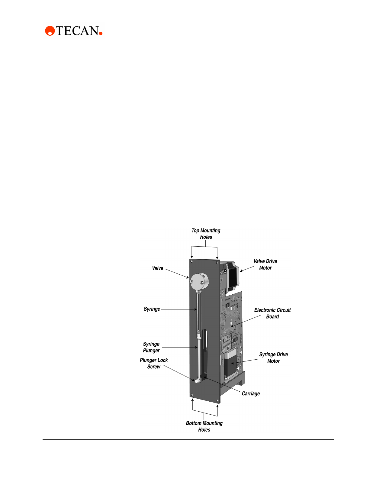
1.4 Functional Description of the XLP 6000
The XLP 6000 uses a stepper-motor driven syringe and valve design to aspirate
and dispense measured quantities of liquid. Both the syringe and the valve are
replaceable. Functional descriptions and illustrations of each major XLP 6000
component are provided in the following sections.
1 - Getting Started
Figure 1-1 XLP 6000 Modular Syringe Pump
Cavro® XLP 6000 Modular Syringe Pump Operating Manual, 734237-C, en 1 - 3
Page 14
1 - Getting Started
Functional Description of the XLP 6000
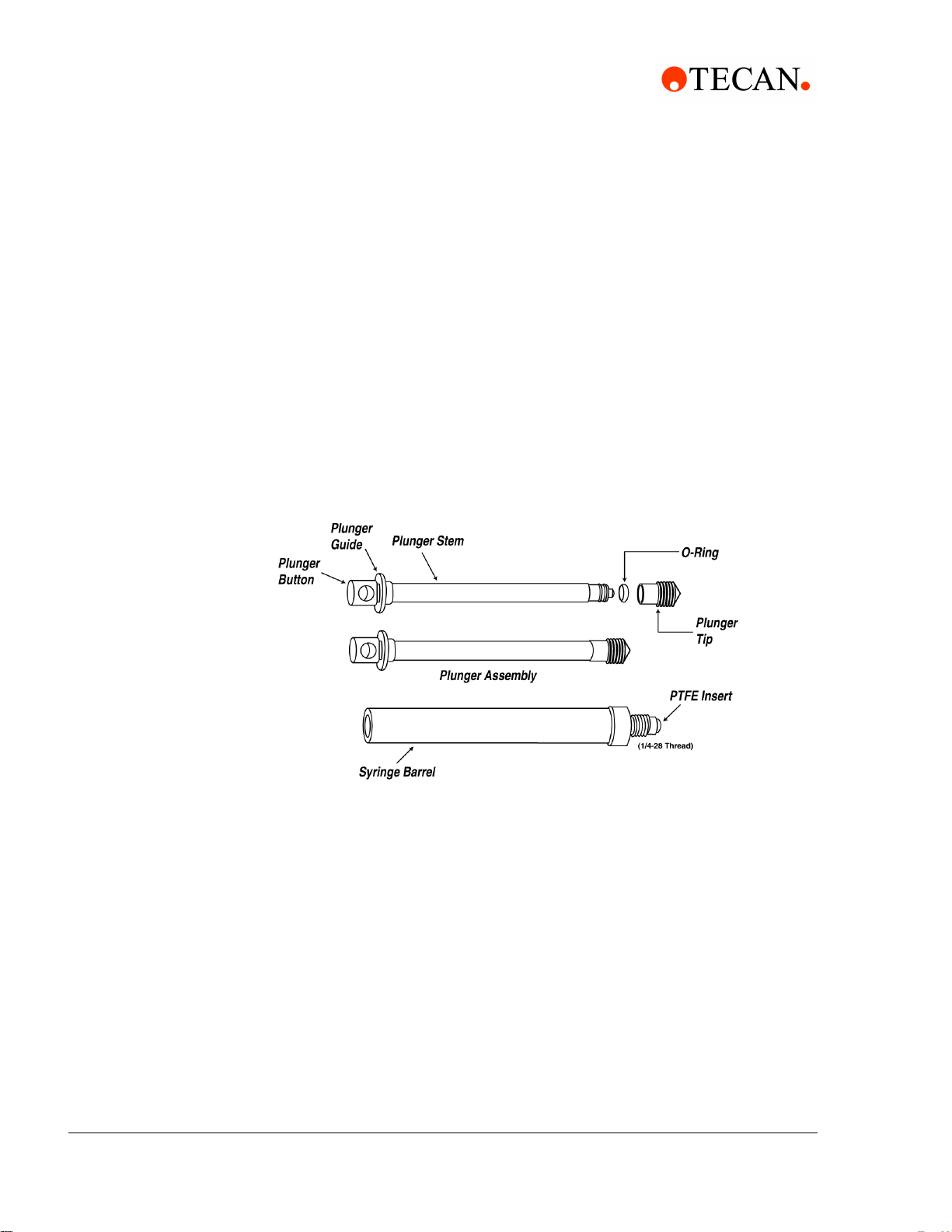
1.4.1 Syringe and Syringe Drive
The syringe plunger is moved within the syringe barrel by a lead screw drive that
incorporates a 1.8 stepper motor and quadrature encoder to detect lost steps.
The syringe drive has a 60 mm travel length and resolution of 6,000 increments
(48,000 increments in fine-positioning and microstep mode). When power is not
applied to the pump, the syringe drive can be removed by releasing the pin
assembly.
The base of the syringe plunger is held to the drive by a knurled screw. The top of
the syringe barrel attaches to the pump valve by a 1/4-28" fitting.
Figure 1-2, ’Syringe Components” shows the components of a typical syringe.
Figure 1-2 Syringe Components
Syringes are available in these sizes: 50 L, 100 L, 250 L, 500 L, 1.0 mL,
2.5 mL, 5.0 mL, 10 mL, and 25 mL.. For ordering information, see Appendix A,
"Ordering Information".
Note: To obtain optimal performance and maximum life from any syringe, please
follow the syringe cleaning and maintenance procedure included with each Cavro
Syringe. Technical Note #1 (PN 730317) contains practical tips for the use and
maintenance of Cavro Syringes.
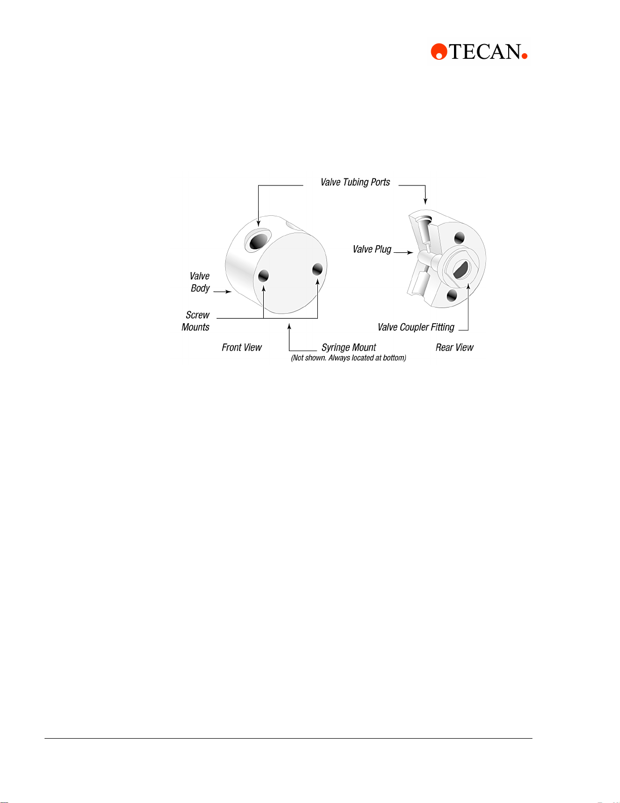
1.4.2 Valve and Valve Drive
The valve is made of a Kel-F body and Teflon plug. The plug rotates inside the
valve body to connect the syringe port to the various input and output ports. In
addition to input and output ports, non-distribution valves also have a bypass
position. This position “bypasses” the syringe and connects the input and output
ports. The bypass position is often used for flushing fluid lines. The valve is turned
by a 1.8 stepper motor that has an encoder coupled to it for positioning feedback.
1 - 4 Cavro® XLP 6000 Modular Syringe Pump Operating Manual, 734237-C, en
Page 15
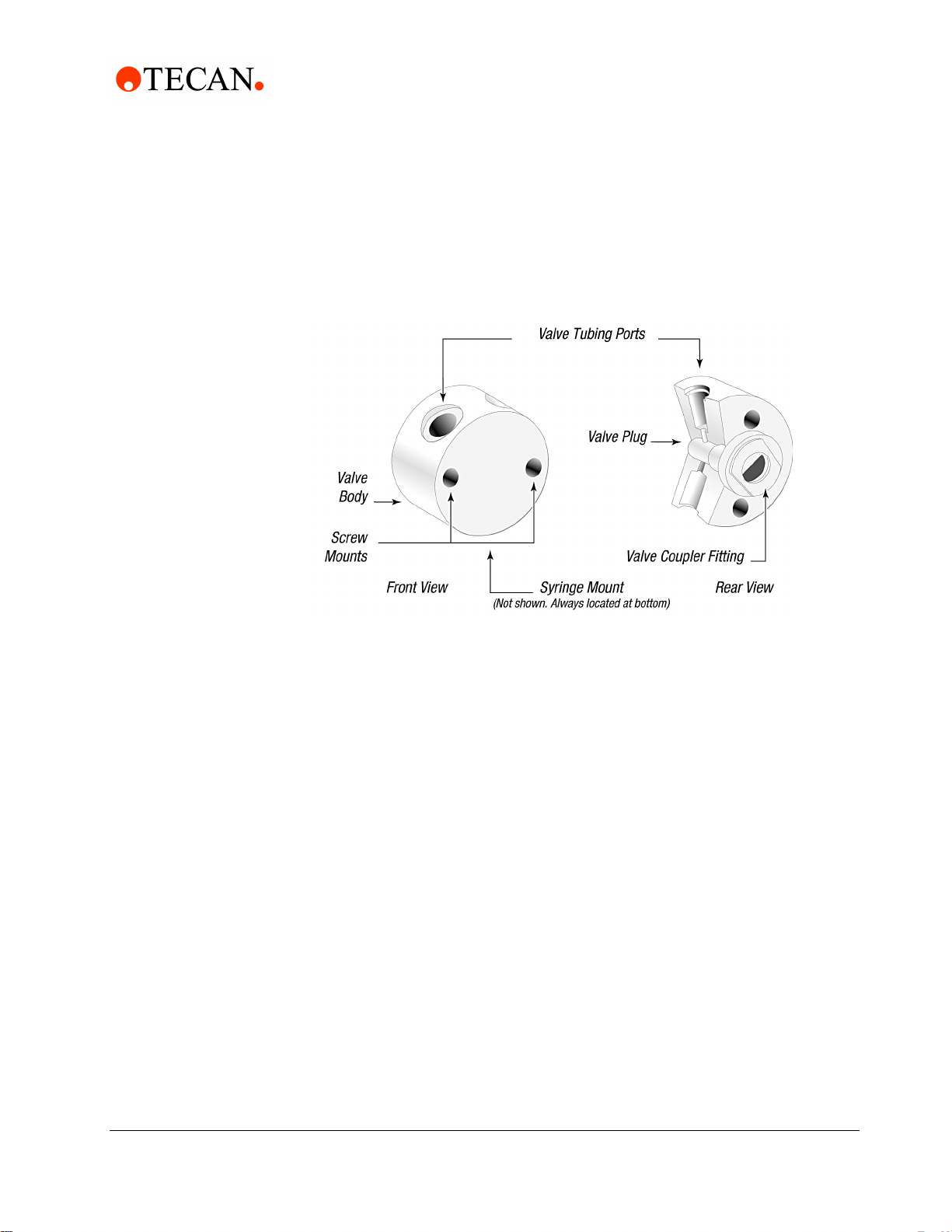
Figure 1-3 shows the components of a 3-port valve.
Figure 1-3 3-Port Valve Components
Functional Description of the XLP 6000
1 - Getting Started
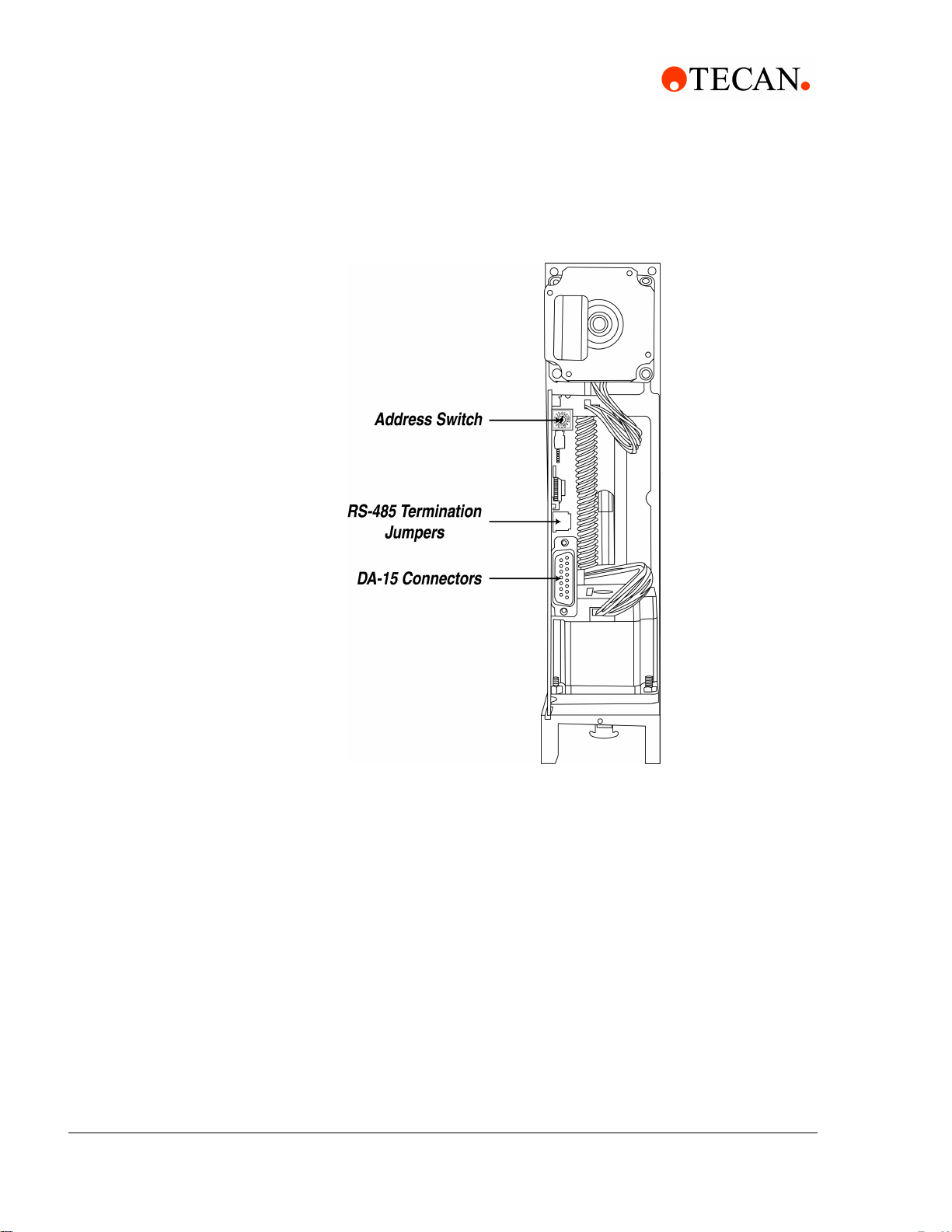
1.4.3 Printed Circuit Assembly
The printed circuit assembly (PCA) holds the microprocessor and circuitry to
control the syringe and valve drive. The PCA provides connectors for electrical
inputs and outputs as well as a communication address switch. For information on
modes of operation, see Chapter 3, "Software Communication".
Figure 1-4 shows the accessible components on the printed circuit board
assembly.
Cavro® XLP 6000 Modular Syringe Pump Operating Manual, 734237-C, en 1 - 5
Page 16
1 - Getting Started
Functional Description of the XLP 6000
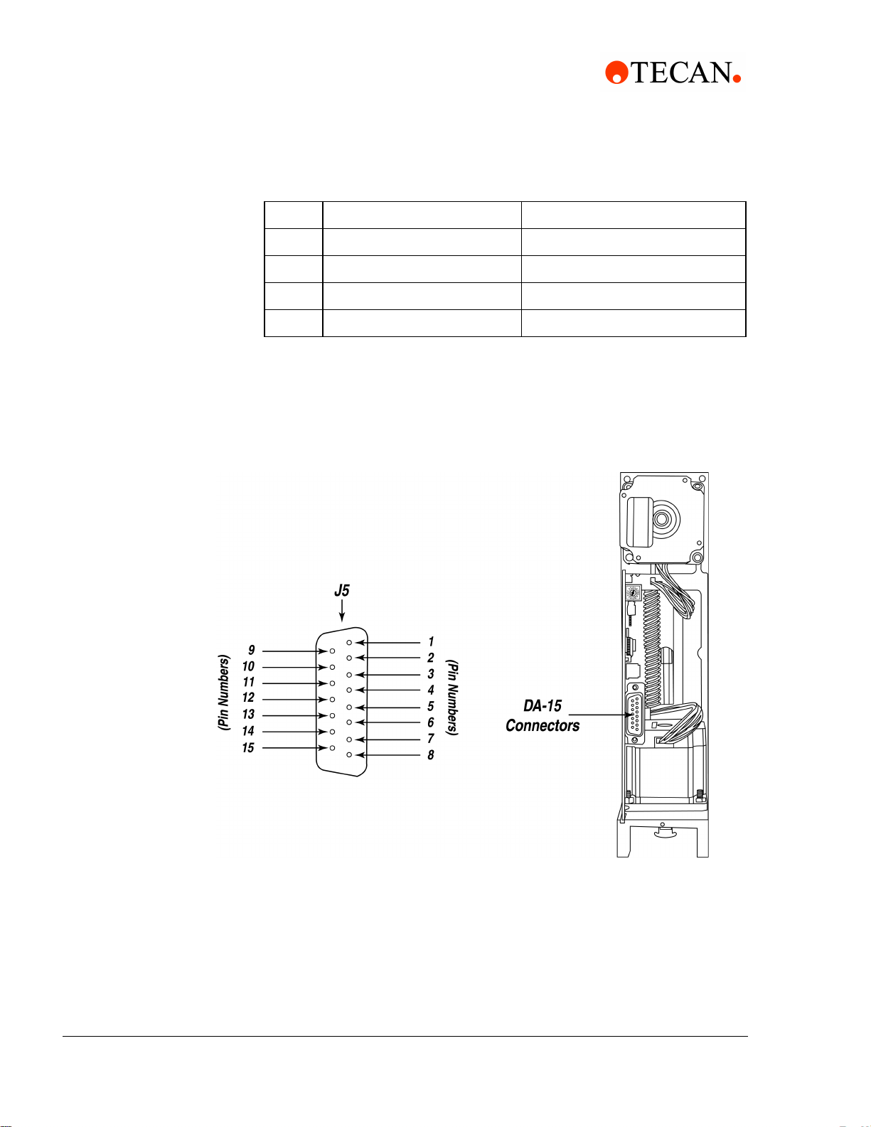
Figure 1-4 XLP 6000 Printed Circuit Assembly External Connectors
The XLP 6000 PCA has a DA-15 connector to handle power and communications.
For more information on the printed circuit assembly inputs/outputs and the
address switch, see Chapter 2, "Hardware Setup".
1.4.4 Communication Interfaces
Depending on the pump configuration, the XLP 6000 can communicate singly or
in a multi-pump configuration through an RS-232, RS-485, or CAN (Controller
Area Network) interface. For RS-232 and RS-485, baud rates of 9600 and 38400
are supported. For CAN, baud rates of 100K,125K, 250K, 500K, and 1M are
supported.
For details on the communications interfaces, see Chapter 2, "Hardware Setup".
1 - 6 Cavro® XLP 6000 Modular Syringe Pump Operating Manual, 734237-C, en
Page 17
1.4.5 Multi-Pump Configurations
Up to fifteen (15) XLP 6000 pumps can be connected together in a multi-pump
configuration (also called “daisy-chaining”). In this configuration each pump is
addressed separately from a single terminal via its unique address, which is set
using the address switch on the back panel of the pump.
Within a multi-pump configuration, the RS-485 communications bus is required,
although the first pump in the chain may receive either RS-232 or RS-485
communications. For CAN communications, neither RS-232 nor RS-485 is
required. For more information on setting addresses, see Chapter 2.
1.5 Safety
1 - Getting Started
Safety
The Cavro® XLP 6000 Modular Syringe Pump is designed for pipetting and
dispensing operations in the 5 µL to 25 mL range. Any other use is considered
improper and may result in damage to the pump and/or unreliable test results.
The XLP 6000 is designed to meet recognized technical regulations and is built
with state-of-the-art components. Nevertheless, risks to users, property and the
environment can arise when the module is used carelessly or improperly.
Appropriate warnings in this Operating Manual serve to make the user aware of
possible hazards.
1.5.1 Notices and Symbols
Warning Notices Used in this Manual
The triangle warning symbol indicates the possibility of personal injury if the
instructions are not followed.
Specific symbols indicate the hazard to which a user is exposed. A few examples
follow.
Toxic Substance
Chemical or biological hazards can be associated with the substances used or the
samples processed with the XLP 6000. Always be aware of possible hazards
associated with these substances.
Explosion and Fire Hazard
Never process explosive or highly flammable liquids with the XLP 6000.
Cavro® XLP 6000 Modular Syringe Pump Operating Manual, 734237-C, en 1 - 7
Page 18
1 - Getting Started
Tips for Setting Up the XLP 6000
Pinch Point, Mechanical Hazards
Automatically moving parts may cause injuries (crushing, piercing)
Attention
The general “Read This” symbol indicates the possibility of equipment damage,
malfunction or incorrect process results, if instructions are not followed.
1.6 Tips for Setting Up the XLP 6000
For complete information on setting up the XLP 6000, see Chapter 2, "Hardware
Setup" and “Chapter 3, "Software Communication".
Note: Before performing any work with the XLP 6000, first read this Operating
Manual carefully.
To ensure proper operation, follow these tips:
Always set up and mount the pump in an upright position. Failure to do so can
cause problems priming the system.
Always run liquid through the syringe and valve when they are moving. Failure
to do so can damage the sealing surfaces.
Before running any organic solvents through the pump, see Appendix D,
"Chemical Resistance Chart" for more information on chemical compatibility.
Always power down the instrument when connecting or disconnecting pumps.
Caution! Keep fingers out of the syringe slot while the pump is running. Failure to
do so can cause injury.
1 - 8 Cavro® XLP 6000 Modular Syringe Pump Operating Manual, 734237-C, en
Page 19

2 Hardware Setup
This chapter includes these sections describing the various parts of hardware
setup:
Power and Electrical Considerations
Cabling
Communication Interfaces
Settings and Options
Installing Components
Mounting
2.1 Power and Electrical Considerations
Power and Electrical Considerations
2 - Hardware Setup
The XLP 6000 requires a 24V DC power supply with a current rating of at least
1.5A, provided through a DA-15 connector. Tecan Systems recommends using
one power cable for every two pumps to provide noise immunity, i.e., power
should not be daisy-chained to more than two pumps.
2.1.1 Choosing a Power Supply
The 24V DC supply for a single XLP 6000 should meet the following basic
requirements:
Output voltage: 24V nominal
Output voltage tolerance: ±10% maximum, ±5% preferred.
Well-regulated power supplies are recommended, as operating pumps below
24V will affect performance.
Output voltage regulation: ±1% with varying line (input voltage) and load
Output current (not including loads other than a single pump):
– 1.5A for power supplies with minimal capacitance.
– 850mA for power supplies with internal filter capacitance of at least 1000
F per amp of output current
– 850mA for power supplies with external capacitance of at least 1000 F
per amp of output current (aluminum electrolytic capacitor preferred)
Output voltage ripple: 50mV rms maximum at full load
Conformance to required safety and EMI/RFI specifications
Voltage turn-on and turn-off overshoot: < 2 volts
Minimum current load (for switchers): see “Switching Power Supplies” in this
chapter.
To meet the above basic requirements, the supply must incorporate either linear
or switching regulation and must have adequate output filter capacitance.
Cavro® XLP 6000 Modular Syringe Pump Operating Manual, 734237-C, en 2 - 1
Page 20

2 - Hardware Setup
Power and Electrical Considerations
A current-limiting power supply is recommended. Current limiting above 1.0A is
acceptable, assuming that no additional equipment is operated from the supply.
If the power supply uses current feedback, the time-current foldback point must be
sufficient to allow charging of a 470 F capacitor without folding back. If an
external capacitor is used, exercise care to ensure that the supply always starts
after foldback, particularly at low AC line voltage.
2.1.2 Integrating a Power Supply
When a power supply is used to operate more than one XLP 6000 or other device,
it must provide the total average current for all devices. The power supply and
filter capacitance together must satisfy the total peak input current for all devices.
For example, if a system incorporates six XLP 6000 pumps with other equipment
that together require 4 amps, a 10A power supply is satisfactory, provided the
output filter capacitance in the supply is at least 10,000 F:
6 x 0.85 = 5.1A; +4A = 9.1A (choose a 10A power supply)
If the power supply filter capacitance is less than 10,000 F, use either additional
external capacitance or a 15A power supply:
6 x 1.5 = 9.0A; +4A = 13A (choose a 15A power supply)
In this example, it is assumed that all the pumps and other equipment will
sometimes operate simultaneously.
External equipment with inadequate bypass capacitance or that is inadequately
sourced for current can cause overvoltage transients and sags, and can create
unnecessary ripple current in the XLP 6000. This can result in decreased
component life. Additionally , it is possible for a regulated power supply to become
unstable with certain loads and oscillate if adequate filter capacitance is not
present. Some forms of oscillation can cause failures in the XLP 6000. These
issues can be avoided by using a properly designed commercial power supply.
Consideration should also be given to the wiring of the XLP 6000 and any
additional devices. Wiring should be of sufficient gauge for the current, and as
short as possible. Unless otherwise required by safety requirements, the power
supply lines to the XLP 6000 should be 20AWG or heavier. Multiple XLP 6000s
can be daisy-chained, provided that the wire size and the power supply are
adequate for the total current. In the example of the six XLP 6000 pumps above,
use 18AWG wire if the units are daisy-chained. It is best if each pair is twisted or
dressed together from the device to the supply. For more information on multipump cabling, see Section 2.2, Cabling.
To control power to the XLP 6000, switch power to the power supply. Do not use a
relay or switch contacts between the 24V supply and the XLP 6000 (i.e., do not
switch DC input to the pump).
2 - 2 Cavro® XLP 6000 Modular Syringe Pump Operating Manual, 734237-C, en
Page 21
2.1.3 Switching Power Supplies
Be sure to check carefully the minimum load requirement of the power supply.
Typically, switching supplies have a minimum load requirement of up to 10% of
the rated output current.
Note: The XLP 6000 idle current is less than 10% of the full running current.
For example, in a system with multiple XLP 6000 pumps, a 24V 5-amp switcher
with a minimum load less that 500mA may not provide sufficient current when the
XLP 6000 motors are idle and all other devices are in a low current state. If the
XLP 6000 is the only load on the 24V supply, a switcher should have a minimum
load specification of 50mA or less. An appropriate external power resistor can be
used to ensure that the minimum load is met.
2 - Hardware Setup
Cabling
2.2 Cabling
A single cable supplies both power and communications to each XLP 6000. A
unique address identifies each pump module. For more information, see “Address
Switch Settings” later in this chapter. See also Chapter 3, "Software
Communication".”
Power requirements are described in Section 2.1, Power and Electrical
Considerations.
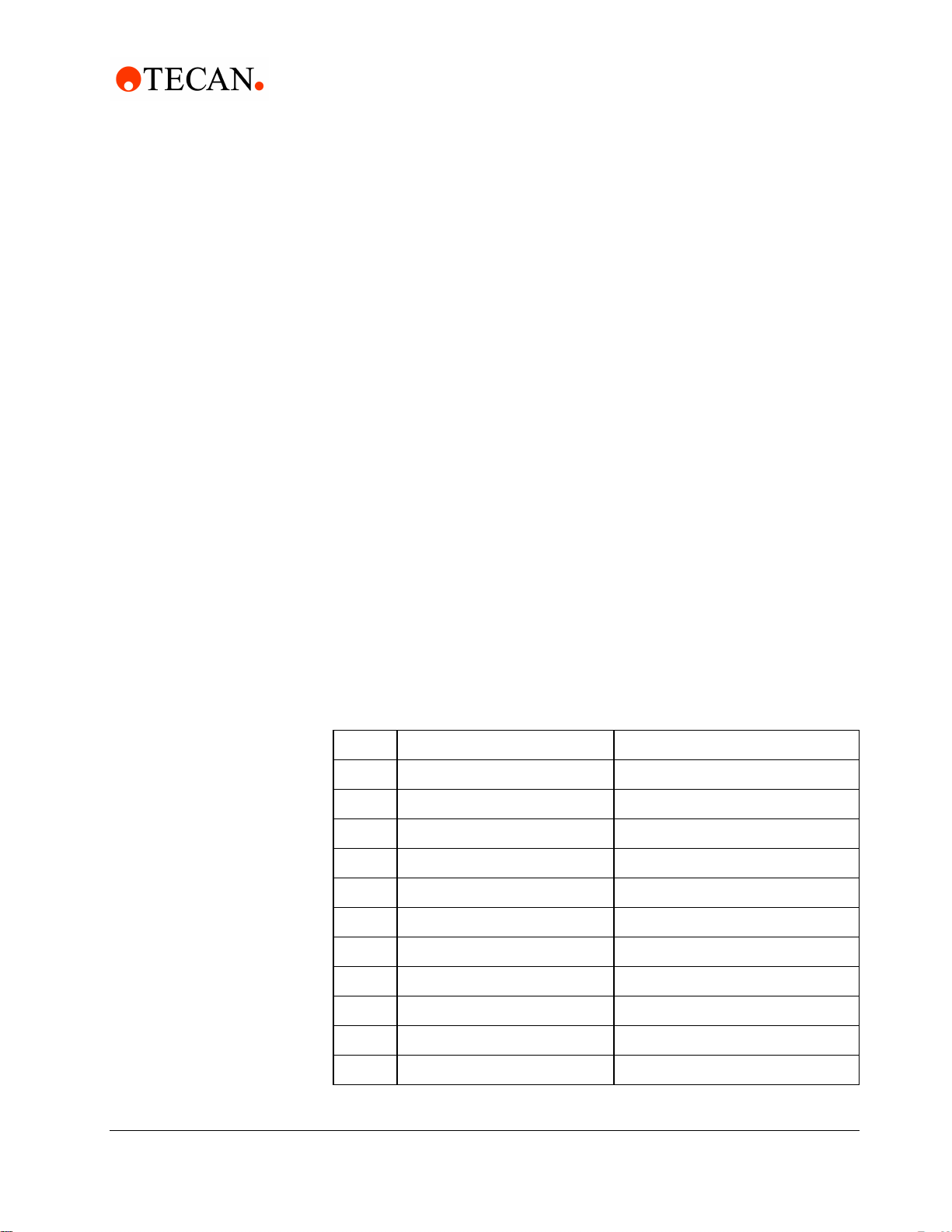
Table 2-1 DA-15 Connector Pin Assignments
Pin Function Remarks
124V DC
2 RS-232 TxD line Output data
3 RS-232 RxD line Input data
4Reserved
5 CAN high signal line
6 CAN low signal line
7 Auxiliary input #1 TTL level
8 Auxiliary input #2 TTL level
9 Ground Power and logic
10 Ground Power and logic
11 RS-485 A line Data +
Cavro® XLP 6000 Modular Syringe Pump Operating Manual, 734237-C, en 2 - 3
Page 22
2 - Hardware Setup
Communication Interfaces
Figure 2-1 DA-15 Connector Pins
Pin Function Remarks
12 RS-485 B line Data 13 Auxiliary output #1 TTL level
14 Auxiliary output #2 TTL level
15 Auxiliary output #3 TTL level
Figure 2-1 shows the pin positions of the DA-15 connector on the printed circuit
assembly. This is a male connector that requires a female connector on the
mating cable.
2.3 Communication Interfaces
The computer or controller communicates with the XLP 6000 through an RS-232
interface, RS-485 interface, or CAN (Controller Area Network) interface.The XLP
6000 automatically detects the communication interface.
2 - 4 Cavro® XLP 6000 Modular Syringe Pump Operating Manual, 734237-C, en
Page 23

Examples of cabling connections are shown in Figure 2-2, Figure 2-3, and
Figure 2-4 on the following pages.
2.3.1 RS-232/RS-485 Interface
The RS-232 interface automatically converts the protocol to RS-485 for the
benefit of any other devices which may be connected to the XLP 6000’s RS-485
communication bus (this constitutes the so-called “multi-drop” device
configuration).
Note: The RS-232 interface does not support hardware handshaking and
requires only three lines: RXD, TXD, and Signal Ground.
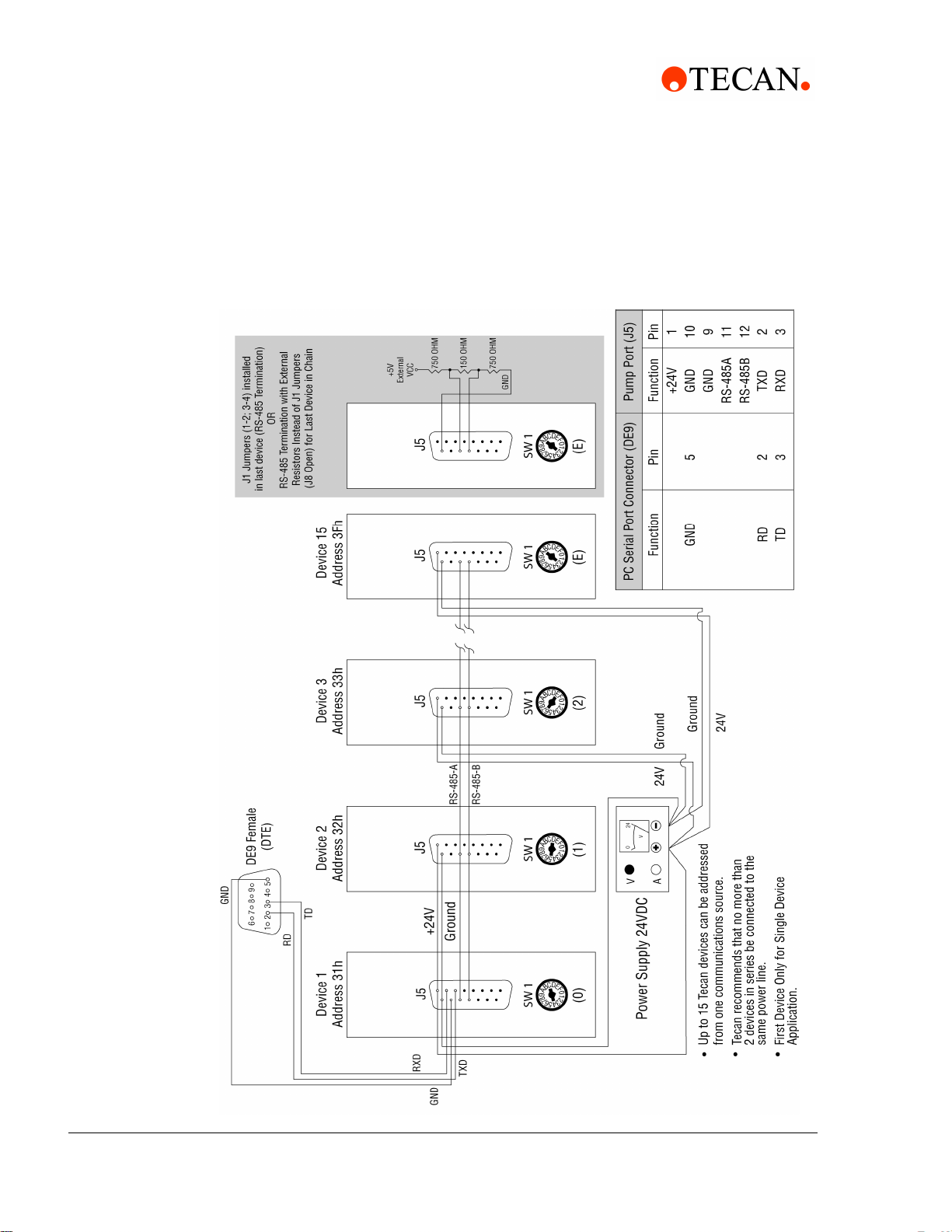
When using a multi-drop arrangement, up to 15 pumps can be addressed by the
controller on the same communications bus. Take special care to ensure that the
RS-485 A and B lines are not reversed. Refer to the cabling illustrations on the
following pages. These illustrations show the multi-pump cabling for RS-232, RS485, and CAN connections, respectively. Also shown is the external termination
scheme for the RS-485 chain.
2 - Hardware Setup
Communication Interfaces
2.3.2 CAN Interface
The CAN interface is a two-wire serial system. The bus is driven differentially in a
manner similar to RS-485. The major difference is in the protocol. The CAN
protocol is designed to allow any device on the bus to send a message at any
time. This is unlike other two-wire interfaces in which the slave devices can only
transmit in response to a query. Using the CAN interface, the pump can send a
message to inform the master that it has completed its task. Anti-collision
detection (which reconciles problems that occur when two devices talk at once) is
carried out by the CAN controller hardware.
Caution! Always power off pumps before connecting to or disconnecting from the
bus.
Cavro® XLP 6000 Modular Syringe Pump Operating Manual, 734237-C, en 2 - 5
Page 24
2 - Hardware Setup
Communication Interfaces
RS-232 Cabling
Figure 2-2 RS-232 Multi-Pump Cabling
2 - 6 Cavro® XLP 6000 Modular Syringe Pump Operating Manual, 734237-C, en
Page 25
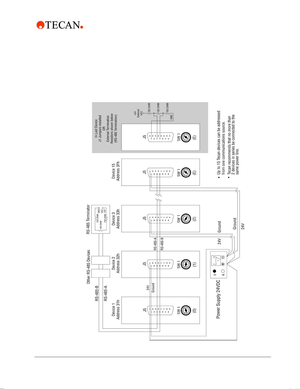
RS-485 Cabling
2 - Hardware Setup
Communication Interfaces
Figure 2-3 RS-485 Multi-Pump Cabling
Cavro® XLP 6000 Modular Syringe Pump Operating Manual, 734237-C, en 2 - 7
Page 26
2 - Hardware Setup
Communication Interfaces
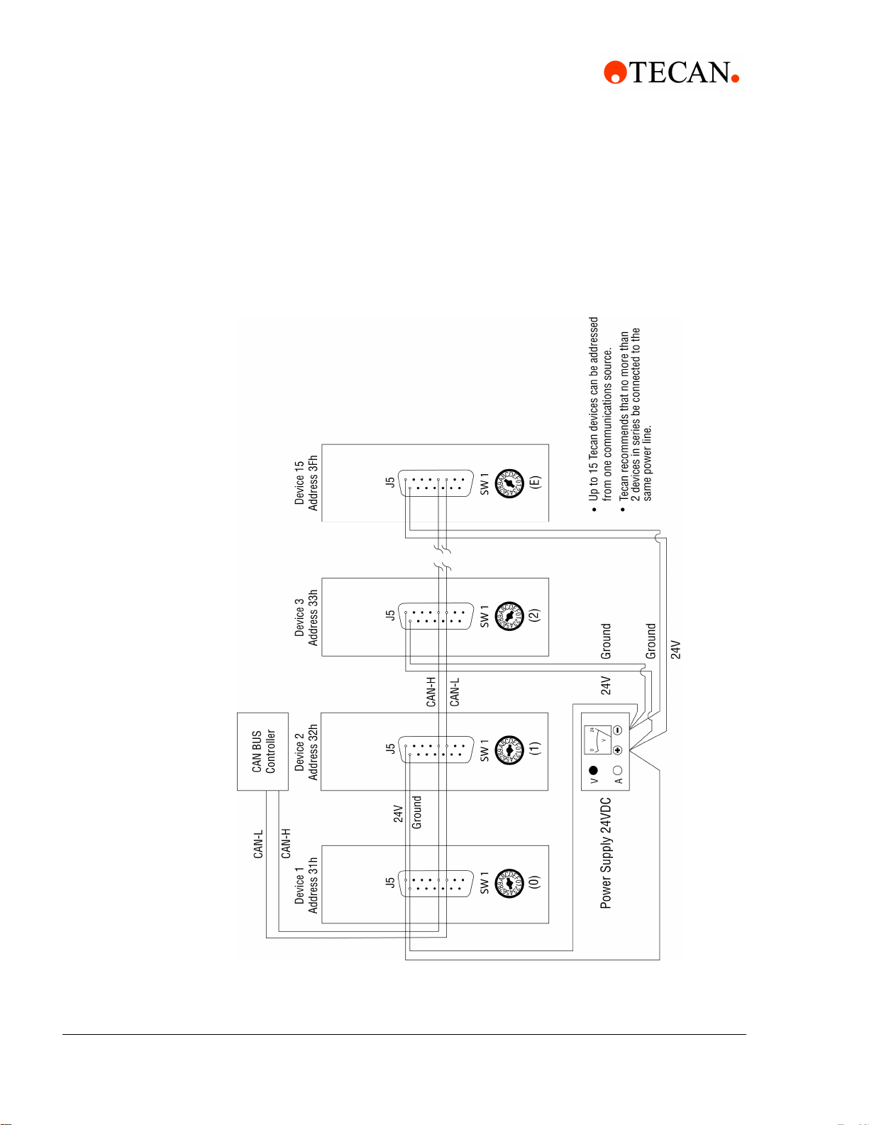
CAN Cabling
Figure 2-4 CAN Multi-Pump Cabling
2 - 8 Cavro® XLP 6000 Modular Syringe Pump Operating Manual, 734237-C, en
Page 27

2.4 Settings and Options
2.4.1 Configuration Commands
The XLP 6000 firmware allows the user to configure the pump for different modes
of operation. The U commands (see Chapter 3, "Software Communication") are
used to write the configuration information to the non-volatile memory and control
the following options:
Valve type: The pump can be configured to operate with different valve
options (3-port, 4-port, T-valve, Y Block, 3-port distribution, 6-port distribution,
and 9-port distribution).
Baud rate: RS-232/RS-485 communication is possible at 9600 baud (default)
and 38400 baud. CAN communication is possible at 100K baud (default),
125K baud, 250K baud, 500K baud, and 1M baud rates.
Non-Volatile Memory Auto Mode: Allows the pump to run command strings
out of the non-volatile memory.
2 - Hardware Setup
Settings and Options
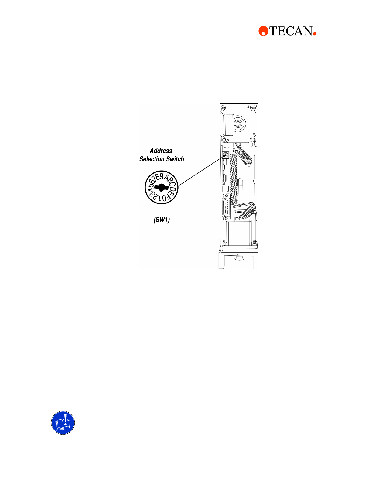
2.4.2 Address Switch Settings
The address switch (see Figure 2-5, "Address Switch") is located near the top of
the XLP 6000 electronic circuit board. It is used to give each XLP 6000 in a multipump configuration a unique or specific address, allowing the user to direct
commands to specific pumps. The address switch has sixteen positions
(numbered 0 through F). Fifteen positions (addresses 0 through E) are valid pump
addresses.
Cavro® XLP 6000 Modular Syringe Pump Operating Manual, 734237-C, en 2 - 9
Page 28
2 - Hardware Setup
Settings and Options
Figure 2-5 Address Switch
To set the address switch:
To set the address switch, use a jeweler’s screwdriver or small flat head
screwdriver and turn the switch in either direction to the desired position.
Note: Power cycle (or power up) the pump after setting the address switch.
For information on the addressing schemes for different pump configurations, see
Chapter 3, "Software Communication".
2.4.3 Self-Test
The “F” address switch position is used to activate the XLP 6000 self-test. Selftest causes the XLP 6000 to initialize, then cycle repeatedly through a series of
plunger movements. The self-test cycles through speed codes 0 to 14. If an error
condition occurs, the pump stops moving.
To run the self-test, set the address switch to position “F.” Then supply power to
the pump.
Caution! Always run liquid through the syringe and valve. Failure to do so can
damage the valve and syringe seal.
2 - 10 Cavro® XLP 6000 Modular Syringe Pump Operating Manual, 734237-C, en
Page 29

2.4.4 J5 Inputs/Outputs
The XLP 6000 provides two auxiliary inputs and three auxiliary outputs that can be
accessed through the DA-15 connector, J5. They provide TTL level signals. The
outputs are controlled by the [J] command.
The auxiliary inputs are located on J5, pins 7 and 8. They can be read back using
report commands ?13 and ?14. Additionally, the inputs can be used to externally
trigger a command sequence using the [H] command. The commands are
described in Chapter 3, "Software Communication".
The auxiliary outputs are located on J5, pins 13, 14, and 15.
2.5 Installing Components
2 - Hardware Setup
Installing Components
2.5.1 Installing the XLP 6000 Valve
To install the XLP 6000 valve, follow these steps:
1 Remove as much fluid as possible from the system by cycling the pump and
using air as the system fluid.
2 Initialize the pump using the [ZR] command so that the valve motor shaft is in
the correct position.
3 Issue an [A6000R] command to move the plunger to the bottom of travel.
4 Remove the syringe and tubing.
5 Remove the two socket head screws on the front of the valve, then remove
the valve from the pump. Do not remove the spacer.
6 Install the new valve by placing it on the front panel so that the screw holes
line up. The valve coupler fitting mates to the valve motor shaft. The shaft
should be in the correct position. If it is not, re-initialize the pump using the
command [ZR].
7 Replace the valve screws but do not tighten completely.
8 Install the syringe and pull the syringe plunger until it is aligned with the
carriage. Align the valve using the plunger as a guide, and tighten from 1/4 to
1/2 turn after the screws contact the valve body.
9 Pull the syringe plunger all the way into the carriage and secure by tightening
the plunger lock screw.
Caution! Be sure to reconfigure the pump firmware when changing valve types.
Failure to do so may damage the valve. See Section 3.3.2, Pump Configuration
Commands, for instructions on reconfiguring the pump.
Cavro® XLP 6000 Modular Syringe Pump Operating Manual, 734237-C, en 2 - 11
Page 30
2 - Hardware Setup
Installing Components
Figure 2-6 XLP 6000 Valve Installation (3-Port Valve Shown)
2.5.2 Installing a Syringe
To install a syringe, follow these steps:
1 Remove the plunger lock screw.
2 Install the syringe as shown in Figure 2-7, following these steps:
a. Screw the syringe into the valve.
b. Pull the syringe plunger down to the plunger holder assembly.
c. Align the plunger button through hole to the carriage mounting hole.
d. Slide the plunger lock screw through the plunger button and fasten to the
carriage.
Note: Make sure the plunger lock screw is securely tightened and the plunger
button is free to move on the plunger lock screw.
2 - 12 Cavro® XLP 6000 Modular Syringe Pump Operating Manual, 734237-C, en
Page 31

Figure 2-7 Syringe Installation
2 - Hardware Setup
Mounting
Note: To obtain optimal performance and maximum syringe life, follow the syringe
cleaning and maintenance procedures described in Chapter 5, "Maintenance".
Technical Note #001 (PN730317) contains practical tips for the tuse and care of
Tecan precision syringes.
2.6 Mounting
The XLP 6000 contains four mounting holes on the front plate of the frame.
Note: Always mount the pump in an upright position. Failure to do so can cause
problems in priming the system.
To facilitate mounting, see Figure 2-8, "XLP 6000 Outline Drawing" for critical
dimensions and location of the mounting holes.
Cavro® XLP 6000 Modular Syringe Pump Operating Manual, 734237-C, en 2 - 13
Page 32

2 - Hardware Setup
Mounting
Figure 2-8 XLP 6000 Outline Drawing
\
2 - 14 Cavro® XLP 6000 Modular Syringe Pump Operating Manual, 734237-C, en
Page 33

3 Software Communication
This chapter describes how to communicate with the XLP 6000: through an
RS-232, RS-485, or CAN (Controller Area Network) interface.
This chapter includes these topics:
XLP 6000 Addressing Scheme
Communication Protocols
Using the XLP 6000 Command Set
Initialization
Operating Commands
Error Codes and Pump Status
3 - Software Communication
XLP 6000 Addressing Scheme
3.1 XLP 6000 Addressing Scheme
As part of the communication protocol, an address for each pump must be
specified. The user has the option of addressing a single pump, two pumps (dual
device), four pumps (quad device), or all 15 pumps (all devices), depending on the
address byte used. Each physical address in the address switch corresponds to a
hexadecimal value, as shown in Table 3-1, Hexadecimal Addressing Scheme.
Table 3-1 Hexadecimal Addressing Scheme
Address (hex)
30 0 Master Address (master controller, personal com-
puter, etc.)
31..3F 1..F Addresses single device
41..4F N/A Addresses two devices at a time (dual device)
51..5D N/A Addresses four devices at a time (quad device)
5F N/A Addresses all devices on the bus
For example, an XLP 6000 with address switch set to 0 is addressed as device
“31h” in the RS-232 or RS-485 communication protocol, hardware address 1 is
addressed as device “32h,” and so on.
DeviceRS-232/RS-485 CAN
Table 3-2, Address Switch Settings in Hex (ASCII), shows the different address
switch settings for each of these configurations.
Note: When using the Pump:Link software to send commands to a device, use
the ASCII address values in Table 3-2.
Cavro® XLP 6000 Modular Syringe Pump Operating Manual, 734237-C, en 3 - 1
Page 34

3 - Software Communication
XLP 6000 Addressing Scheme
Table 3-2 Address Switch Settings in Hex (ASCII)
Single Device Dual Device Quad Device All Devices
Switch
Setting
0 31 1 41 A 51 Q 5F –
1322
233343C
3344
435545E55 U
5366
637747G
7388
839949I59 Y
93A:
A3B;4BK
B3C<
C3D=4DM5D ]
D3E>
Hex
Address
ASCII
Address
Hex
Address
ASCII
Address
Hex
Address
ASCII
Address Address
Value to
Send
E3F?4FO
FSelf Test
The user can communicate with all pumps in the chain by using address “5Fh,” for
example to initialize all pumps at once. Then each pump can be controlled
independently by using addresses “31h” to “3Fh.”
Note: Multiple address commands cannot be used to determine device status or
to request reports. Each device must be queried separately to gather status or
generate a report.
3 - 2 Cavro® XLP 6000 Modular Syringe Pump Operating Manual, 734237-C, en
Page 35

3.2 Communication Protocols
Three communication protocols are available:
OEM communications protocol
Data Terminal (DT) protocol
CAN protocol
The XLP 6000 firmware automatically detects the communication protocol.
The DT protocol can be run via an ASCII data terminal because no sequence
numbers or checksums are used. For instructions on using a Microsoft Windows
Terminal Emulator, see “Using DT Protocol with Microsoft Windows” in this
chapter.
Note: Tecan Systems recommends using the OEM protocol for RS-232 and
RS-485 interfaces. It provides increased error checking through the use of
checksums and sequence numbers.
3 - Software Communication
Communication Protocols
Once the XLP 6000 detects either the OEM or DT protocol, it will ignore the other
protocol until the next power cycle.
3.2.1 OEM Communication Protocol
OEM communication is a robust protocol that includes automatic recovery from
transmission errors. Table 3-3, OEM Protocol describes each setting within the
OEM communication protocol.
Table 3-3 OEM Protocol
Parameter Setting
Character Format
Baud rate 9600 or 38400
Data bits 8
Parity None
Stop bit 1
Command Block
(see “OEM Protocol Command Block Characters” for details)
1 STX (^B or 02h)
2 Pump address
3 Sequence number
3+n Data block (length n)
Cavro® XLP 6000 Modular Syringe Pump Operating Manual, 734237-C, en 3 - 3
Page 36

3 - Software Communication
Communication Protocols
4+n ETX (^C or 03h)
5+n Checksum
1 STX (^B or 02h)
2 Master address (0 or 30h)
3 Status code
3+n Data block (length n)
4+n ETX (^C or 03h)
5+n Checksum
Answer Block
(see “OEM Protocol Answer Block Characters” for details)
OEM Protocol Command Block Characters
The command block characters in the OEM communication protocol are
described below. All characters outside the command block are ignored.
When developing a parsing algorithm, the programmer should key on the STX as
the beginning of the answer block and the checksum (character after the ETX) as
the end of the answer block.
STX (^B or 02h)
The STX character indicates the beginning of a command
Pump Address
The pump address is a hexadecimal number specific for each pump.
Sequence Number/Repeat Flag
The sequence number is a single byte that conveys both a sequence number
(legal values: 0 to 7) and a bit-flag indicating that the command block is being
repeated due to a communications breakdown. The sequence number is used
as an identity stamp for each command block. Since it is only necessary that
every message carry a different sequence number from the previous
message (except when repeated), the sequence number may be toggled
between two different values (e.g., “1” and “2”) as each command block is
constructed. During normal communication exchanges, the sequence number
is ignored. If, however, the repeat flag is set, the pump compares the
sequence number with that of the previously received command block to
determine if the command should be executed or merely acknowledged
without executing.
Note: If the operator chooses not to use this option, the sequence number can be
set to a fixed value of 1 (31h).
3 - 4 Cavro® XLP 6000 Modular Syringe Pump Operating Manual, 734237-C, en
Page 37

3 - Software Communication
Communication Protocols
The following two scenarios clarify this error detection mechanism.
Scenario 1.
1 The computer sends a command block stamped with sequence #1 to the
pump.
2 The pump receives the command, sends an acknowledgement to the PC, and
executes it.
3 Transmission of the acknowledgement message is imperfect; the PC does not
receive it.
4 The PC waits 100 ms for the acknowledgement, then retransmits the
command block with the sequence number left at 1 and the repeat bit set to
indicate a retransmission.
5 The pump receives the transmission, identified as such by the repeat bit.
6 The pump checks the sequence number against that of the previously
received command block. Noting a match, the pump sends an
acknowledgement to the PC, but it does not execute the command (since it
has already been executed).
7 The PC receives the acknowledgement and continues with normal
communications.
8 The next command block is stamped with sequence #2 to indicate a new
command.
Scenario 2.
1 The computer sends a command block stamped with sequence #1 to the
pump.
2 The pump never receives the command due to a communication error and
thus does not send an acknowledgement to the PC.
3 The PC waits 100 ms for the acknowledgement, then retransmits the
command block with the sequence number left at 1 and the repeat bit set to
indicate a retransmission.
4 The pump receives the retransmission, identified as such by the repeat bit.
5 The pump checks the sequence number against that of the previously
received command block. Noting a mismatch, the pump recognizes this as a
new command block and sends an acknowledgement to the PC. It then
executes the command.
6 The PC receives the acknowledgement and continues with normal
communications.
7 The next command block is stamped with sequence #2 to indicate a new
command.
The sequence number/repeat byte is constructed as follows:
Bit # 76543210
Value 0011REPSQ2SQ1SQ0
Cavro® XLP 6000 Modular Syringe Pump Operating Manual, 734237-C, en 3 - 5
Page 38

3 - Software Communication
Communication Protocols
REP
SQ0 – SQ2
0 for non-repeated / 1 for repeated
Sequence value, as follows:
Sequence Value SQ2 SQ1 SQ0
1001
2010
3011
4100
5101
6110
7111
Note: Bits 4 through 7 are always fixed to the values shown.
Data Block (length n)
The data block consists of the data or commands sent to the pump or host
(this is an ASCII string). When the pump is responding to a move or [Q]
command, the data block length is 0 (i.e., no data string exists).
ETX
The ETX character indicates the end of a command string.
Checksum
The checksum is the last byte of the message string. All bytes (excluding line
synchronization and checksums) are XORed to form an 8-bit checksum. This
is appended as the last character of the block. The receiver compares the
transmitted value to the computed value. If the two values match, an error free
transmission is assumed; otherwise, a transmission error is assumed.
OEM Protocol Answer Block Characters
The answer block characters in the OEM communication protocol are described
below.
Only the unique answer block entries are listed in this section. For common
commands and answer block commands (characters), see the previous section,
“OEM Protocol Command Block Characters.”
3 - 6 Cavro® XLP 6000 Modular Syringe Pump Operating Manual, 734237-C, en
Page 39

Master Address
The master address is the address of the host system. This should always be
30h (ASCII value “0”).
Status and Error Codes
The status and error codes define pump status and signal error conditions.
For a description of status and error codes, see “Error Codes and Pump
Status” in this chapter.
3.2.2 Data Terminal (DT) Protocol
The DT protocol can be used easily from any terminal or terminal emulator
capable of generating ASCII characters at 9600 baud, 8 bits, and no parity.
Table 3-4 DT Protocol
3 - Software Communication
Communication Protocols
Character Format
Parameter Setting
Baud rate 9600 or 38400
Data bits 8
Parity None
Stop bit 1
Command Block
(see “DT Protocol Command Block Characters” for details)
1 Start command (ASCII “/” or 2Fh)
2 Pump address
2+n Data block (length n)
3+n Carriage Return ([CR] or 0Dh)
Answer Block
(see “DT Protocol Answer Block Characters” for details)
1 Start answer (ASCII “/” or 2Fh)
2 Master address (ASCII “0” or 30h)
3 Status character
Cavro® XLP 6000 Modular Syringe Pump Operating Manual, 734237-C, en 3 - 7
Page 40

3 - Software Communication
Communication Protocols
3+n Data block (if applicable)
4+n ETX (03h)
5+n Carriage return (0Dh)
6+n Line feed (0Ah)
DT Protocol Command Block Characters
The command block characters in the DT communication protocol are described
below.
Start Block
The start character indicates the beginning of a message block.
Pump Address
The pump address is an ASCII character specific to each pump.
Data Block (length n)
The data block consists of the ASCII data or commands sent to the pump or
host.
End Block
The end character indicates the end of a message block.
DT Protocol Answer Block Characters
The answer block characters comprising the DT communication protocol are
described below.
Only unique answer block entries are listed in this section. For information on
command and answer block commands (characters), see the previous section,
“OEM Protocol Command Block Characters.”
Master Address
The master address is the address of the host system. This should always be
30h (ASCII “0”).
Status Character
The status and error codes define pump status and signal error conditions.
See the description of the [Q] command in “Error Codes and Pump Status.”
Data Block
This is the response from all Report commands with the exception of the [Q]
command.
3 - 8 Cavro® XLP 6000 Modular Syringe Pump Operating Manual, 734237-C, en
Page 41

Carriage Return (0Dh)/Line Feed (0Ah)
This character terminates the reply block.
3.2.3 Using DT Protocol with Microsoft Windows
The XLP 6000 can be controlled in DT protocol mode directly from the Microsoft
Windows terminal accessory.
To communicate with the XLP 6000 using Windows 3.x, follow these steps:
1 Connect the XLP 6000 to a communications port of the PC (for example,
COM1).
2 From the Microsoft Program Manager window, select Terminal from the
Accessories group window.
3 Select the Settings menu, and choose Communications.
4 Select a baud rate of 9600, 8 data bits, 1 stop bit, no parity, communications
port connector, and no flow control.
5 Click OK.
6 Set the pump address switch to 0.
7 Power on the pump.
8 Type /1ZR<CR> to initialize the pump.
9 To run the pump, see the commands listed in “Using the XLP 6000 Command
Set” in this chapter.
3 - Software Communication
Communication Protocols
To communicate with the XLP 6000 using Windows 95/98/NT/2000/XP, follow
these steps:
1 To connect the XLP 6000 to a communications port on the PC, first select the
Start Programs/Accessories/Communications Hyperterminal menu and
choose Run.
2 In the Run dialog box, type Hyperterm.exe. The Connection Description
dialog box appears.
3 Enter a name for the connection and select an icon, then click OK. The Phone
Number dialog box appears.
4 Select the following in the fields provided:
Connect using: Direct to <communication port> (usually COM1 or COM2,
depending on how the hardware is set up)
Click OK. The COM Properties dialog box appears.
5 Select the following in the fields provided:
– Bits per second: 9600
– Data bits: 8
–Parity: None
– Stop bits: 1
– Flow control: None
Cavro® XLP 6000 Modular Syringe Pump Operating Manual, 734237-C, en 3 - 9
Page 42

3 - Software Communication
Communication Protocols
6 Click OK.
7 Select the File menu, and choose Properties. The Properties dialog box
8 Select the Settings tab, and enter or select these options:
9 Enter or select these options:
10 Click OK to close the ASCII Setup dialog box, then click OK to close the
11 Set the pump address to 0 or the appropriate address.
12 The communication protocol is detected automatically.
13 Power on the pump and initialize it by typing /1ZR and pressing Enter.
appears.
– Function, arrow, and Control keys act as:
• Select “Terminal keys”
– Emulation:
• Select “Autodetect”
• Enter “500” in Backscroll buffer lines
– Click the ASCII Setup button. The ASCII Setup dialog box appears.
– Select “Send line ends with line feed”
– Select “Echo typed characters locally”
– Enter a Line delay of “0”
– Enter a Character delay of “0”
– Select “Wrap lines that exceed terminal width”
Properties dialog box.
To run the pump, see the commands listed in “Using the XLP 6000 Command
Set” in this chapter.
3.2.4 CAN Interface Communications
CAN (Controller Area Network) is a two-wire, serial communication bus. It
eliminates polling sequences that verify task completion. Using CAN, the pumps
asynchronously report to the master or host when they have finished the current
task.
Note: All Tecan XLP 6000 systems use CAN controller chips compatible with
Phillips Semiconductor CAN bus specification, version 2.0.
When using the CAN interface, termination resistors (120 ohm) are necessary at
both ends of the bus. The pump does not provide CAN termination resistors.
CAN Messages
CAN messages consist of frames. Each frame has an 11-bit Message Identifier
(MID) and a 4-bit length identifier. The bits:
Indicate to which device on the bus the message is directed
Identify the message type
Show the direction of the message (to or from the master device)
3 - 10 Cavro® XLP 6000 Modular Syringe Pump Operating Manual, 734237-C, en
Page 43

Represent the length of the data block. Data blocks can be from zero to eight
bytes in length. Any message that requires more than eight bytes must be
sent in a series of multi-frame messages. The receiving unit then assembles
the separate frames into one long string.
CAN Message Construction
Each message frame begins with the Message ID (MID). The data block (up to 8
bytes in length) follows the MID and length information. The MID makes up three
nibbles that are transmitted first in a message frame. The bits are grouped as
shown in Figure 3-1, ’CAN Message Structure”.
Figure 3-1 CAN Message Structure
3 - Software Communication
Communication Protocols
Direction
This is the direction bit. It lets the devices on the bus know whether the current
message is to or from the master. “0” means that the message is from master
to slave; “1” means the message is from the slave to the master.
Note: Peer-to-peer messaging is not supported.
Group
This is the group number (0 - 7). Each type device on the CAN bus has a
group assignment. The XLP 6000 is assigned to group 2. The group number
“1” is reserved for the boot request procedure.
Cavro® XLP 6000 Modular Syringe Pump Operating Manual, 734237-C, en 3 - 11
Page 44

3 - Software Communication
Communication Protocols
Device
Frame
RTR
IDE
This is the address of the module in the particular group. Each group can have
up to 16 devices. The address value is 0 - 15.
This lets the device know what type of message is coming. See “CAN Frame
Types” in this chapter.
This bit is not used in T ecan Systems’ CAN implementation and should always
be set to 0.
This will always be set to 0 for standard format frames.
r0
Reserved bit, set to 0.
Length
This is the length of the data block in the message. Data blocks can be from
zero to eight bytes in length.
CAN Frame Types
The frame types allow each device to know what type of command is coming in
and enables faster processing of commands. Pumps respond to the frame types
described below.
“On-the-Fly” Commands (V and T), Type 0
Normal commands use a frame type 1 (i.e., “Action Commands”). Since
commands sent over the CAN bus with a particular frame type must complete
before a subsequent command using the same frame type can be issued, a
different ID must be used when issuing an “on-the-fly” command. For this
reason, “on-the-fly” commands must be issued over the CAN bus with a frame
type of 0 (zero).
When issuing “on-the-fly” commands, the frame type 0 commands will not
generate completion messages and thus no pairing code is needed (these
commands are simply acknowledged immediately).
Action Frames, Type 1
This frame type is used for action commands, such as Initialization
commands, Movement commands, Valve commands, or to set pump
operating parameters. All “task-type” commands are sent in this type
message frame. When multi-frame messages are used to send an action
command, this frame is the end message sent to the pump.
3 - 12 Cavro® XLP 6000 Modular Syringe Pump Operating Manual, 734237-C, en
Page 45

3 - Software Communication
Communication Protocols
Common Commands, Type 2
This frame type is used for commands that are common to every device on
the bus. The frame type is set to 2 and the command is a single ASCII
character in the data block. The single ASCII character is described below.
Command Description
0 Reset mode. This resets the pump and begins the boot request
procedure.
1 Start loaded command. Just like sending an [R] command after a string
has been loaded.
2 Clear loaded command. This clears out the command buffer.
3 Repeat last command. This command does the same thing as the [X]
command.
4 Stop action immediately. This acts like a [T] command.
Multi-Frame Start Message, Type 3
This frame type lets the pump know that the next message will be longer than
the 8-byte maximum for each frame. Subsequent frames will follow to
complete the message.
Multi-Frame Data, Type 4
This frame type is used to identify a frame in the middle of a multi-frame
message. The last frame of a multi-frame message for action commands must
be type 1. The last frame of a multi-frame message response from the pump
for report commands will be type 6.
Note: There is no type 5 frame.
Report/Answer Commands, Type 6
This frame type is used to get information back from the pump. It is similar in
operation to the query commands (i.e., [?]) used in the OEM and DT
protocols. The report command is one byte long and consists of one or more
ASCII characters in the data block. Report commands in ASCII format are:
Command Description
0 Report calculated plunger position in increments (standard/fine position-
ing)
1 Report start speed in increments per second
2 Report top speed in increments per second
3 Report cutoff speed in increments per second
Cavro® XLP 6000 Modular Syringe Pump Operating Manual, 734237-C, en 3 - 13
Page 46

3 - Software Communication
Communication Protocols
6 Report current valve position
10 Report buffer status
13 Report status of input #1
14 Report status of input #2
15 Report the number of pump initializations
16 Report the number of plunger movements
17 Report the number of valve movements
18 Report the number of valve movements since last report
20 Report checksum
23 Report firmware version
24 Report zero gap increments
29 Report current status
When the pump responds to a query, the first two bytes of the data block are the
status bytes. The first byte contains an error code (same error codes used with
the RS-232 and RS-485 protocols) added to Ox20h. The second byte contains the
value Ox60h and is not used. The remaining six bytes are for the response in
ASCII. If the pump is only reporting current status, the message is only two bytes
long. If the reply consists of more than six bytes, multi-frame messages are used.
CAN Data Block
The data block tells the pump what to do. Pump commands are sent in ASCII just
like in RS-232 or RS-485. For command strings that are more than eight bytes in
length, multi-frame messages are used. This permits long program strings to be
sent as with the other communications interfaces (remember that the XLP 6000
buffer size is 255 characters).
Handling of Pump Boot Requests
When the pump is first powered up or receives a system reset command (frame
type 2, command 0), the pump notifies the host of this condition by sending a boot
request message at 100 millisecond intervals until it receives a proper response.
The group number is 1 for the boot request message. The frame type is 2 when
the pump sends messages to the host, and the frame type must be 0 when the
host replies to the boot request.
3 - 14 Cavro® XLP 6000 Modular Syringe Pump Operating Manual, 734237-C, en
Page 47

3 - Software Communication
Communication Protocols
Example 1. The pump is set to address 0
Pump sends:
Dir Group Device Frame RTR Length
1 001 0000 010 0 0000
Host acknowledges:
Dir Group Device Frame RTR Length Node ID Slave ID
0 001 0000 000 0 0010 0010 0000 0010 0000
Host acknowledges the boot request with:
Dir = 0 Host to slave Note:
Group = 1 Boot request response group
Device = 0 Always 0 in boot response
Boot MID is the same for
all nodes
Frame = 0 Boot request response frame
RTR = 0 Always 0
Length = 2 Two data bytes in return message
Node ID Group ID (2) +
Pump Address (0)
Slave ID Same as Node ID
(hex 20)
“ ” 00h Must respond with
“ ” 00h
Group & Address
Cavro® XLP 6000 Modular Syringe Pump Operating Manual, 734237-C, en 3 - 15
Page 48

3 - Software Communication
Communication Protocols
Example 2. The pump is set to address 6
Pump sends:
Dir Group Device Frame RTR Length
1 001 0110 010 0 0000
Host acknowledges:
Dir Group Device Frame RTR Length Node ID Slave ID
0 001 0000 000 0 0010 0010 0110 0010 0110
Host acknowledges the boot request with:
Dir = 0 Host to slave Note:
Group = 1 Boot request response group
Device = 0 Always 0 in boot response
Boot MID is the same for
all nodes
Frame = 0 Boot request response frame
RTR = 0 Always 0
Length = 2 Two data bytes in return message
Node ID Group ID (2) +
Pump Address (6)
Slave ID Same as Node ID
(hex 26)
“&” Hex 26
Hex 26
The pump will save the Node ID to use for message filter Group ID.
Note: The slave ID does not have to be the same as the node ID. The pump can
be assigned any number between 0 and 0x7F (127) for the slave ID.
CAN Host and Pump Exchanges
When a slave pump receives a command, finishes a command, encounters an
error condition, or responds to a query , it sends an answer frame to the host using
the same frame type as the command it belongs to. The answer frame format is
device dependent. Generally, it will have the following format:
<MID><DLC><Answer>
<MID>
11-bit message identifier. The direction bit is 1. The group number and the
frame type are the same as received. Device ID is the slave message ID
assigned by the host.
3 - 16 Cavro® XLP 6000 Modular Syringe Pump Operating Manual, 734237-C, en
Page 49

3 - Software Communication
Communication Protocols
<DLC>
4-bit data length code
<Answer>
Data bytes block. The first byte of the data block is always the status byte,
which is an error code (same error codes used with the RS232 and RS485
protocols) added to Ox20h. The second byte is always Ox60h. The remaining
bytes contain the response in ASCII format. If the reply consists of more than
six bytes, the multi-frame messages are used.
Note: Only one command of a given frame type can be in progress at any one
time; e.g., after issuing a command to a slave pump with frame type = 1, the
master must wait for the answer with frame type = 1 before issuing the next
command with frame type = 1. If the user insists on sending the command, a
command overload status results.
Several commands with different frame types can be in progress at the same
time; e.g., an action command and a query command.
Following are typical exchanges between the host and slave for action
commands, multi-frame commands, common commands, and query commands.
Action Command
The host commands [ZR] to a pump, and the pump is set to address 0.
Host sends:
0 XXXXXXX 001 0 0010 ZR
Dir Slave ID Frame Type RTR DLC Data bytes
Pump acknowledges:
1 XXXXXXX 001 0 0000
Dir Slave ID Frame Type RTR DLC
After executing the command, pump reports status:
1 XXXXXXX 001 0 0010 <20h><60h>
Dir Slave ID Frame Type RTR DLC Data bytes
Note: The mixed formats ASCII and hexadecimal are used in the data bytes
block. The hexadecimal number is bracketed (< >). The rest of the fields are
displayed in binary format.
Cavro® XLP 6000 Modular Syringe Pump Operating Manual, 734237-C, en 3 - 17
Page 50

3 - Software Communication
Communication Protocols
Multi-Frame Command
The host commands [Z2S5gIA3000OgHD300G10G5R] to a pump, and the pump
is set to address 0.
Host sends:
0 XXXXXXX 011 0 1000 Z2S5gA3
Dir Slave ID Frame type RTR DLC Data bytes
0 XXXXXXX 100 0 1000 000OgHD30
Dir Slave ID Frame type RTR DLC Data bytes
0 XXXXXXX 001 0 1000 00G10G5R
Dir Slave ID Frame type RTR DLC Data bytes
Pump acknowledges:
1 XXXXXXX 001 0 0000
Dir Slave ID Frame type RTR DLC
After executing the command, pump reports status:
1 XXXXXXX 001 0 0010 <20h><60h>
Dir Slave ID Frame type RTR DLC Data bytes
Note: For multi-frame commands, the pump only acknowledges the last frame.
Common Command
After the host has sent command [A1000A0] to the pump, it sends command 0 of
frame type 2 to a pump and makes the pump move. The pump is set to address 0.
Host sends:
0 010 0000 010 0 0001 1
Dir Group Device Frame type RTR DLC Data bytes
Pump does not acknowledge common commands.
Pump does not report status after common commands.
Query Command
The host commands 29 of frame type 6 to a pump, and the pump is set to address
1.
3 - 18 Cavro® XLP 6000 Modular Syringe Pump Operating Manual, 734237-C, en
Page 51

3 - Software Communication
Communication Protocols
Host sends:
0 XXXXXXX 110 0 0010 29
Dir Slave ID Frame Type RTR DLC Data bytes
Pump reports:
1 XXXXXXX 110 0 0010 <20h><60h>
Dir Slave ID Frame Type RTR DLC
Note: For query commands, no acknowledge frame is needed.
Report Command
The host sends command report 23 of frame type 6 to a pump, and the pump is
set to address 1.
Host sends:
0 XXXXXXX 110 0 0010 23
Dir Slave ID Frame
Type
Pump reports:
1 XXXXXXX 011 0 1000 <20h><60h><XLP60>
Dir Slave ID Frame
Type
1 XXXXXXX
Dir Slave ID
100 0 0111 00 - Vx.x.
Frame
Type
RTR DLC Data bytes
RTR DLC
x<20h>x/200x (frame type 4)
<20h>734604<20h>
(frame type 4)
Rev <20h>X (frame type 6)
RTR DLC Data bytes
Note: For a multi-frame reply, the start frame is type 3, the middle frame is type 4,
and the last frame is type 6.
Cavro® XLP 6000 Modular Syringe Pump Operating Manual, 734237-C, en 3 - 19
Page 52

3 - Software Communication
Using the XLP 6000 Command Set
3.3 Using the XLP 6000 Command Set
The XLP 6000 features a robust command set which allows a wide range of
parameters to be defined by the user. Many of the commands have default
values; however, the default values may not provide the optimal settings for your
application. Take a moment to familiarize yourself with each command in order to
obtain the best performance for your application.
For a quick summary of all commands, see Appendix G, "Command Quick
Reference".
When problems are detected, the XLP 6000 sends an error code. The error codes
are described in “Error Codes” at the end of this chapter.
Note: Some commands are invalid in the CAN interface. For a list of these
commands, see Appendix F, "CAN Communication Commands".
3.3.1 Command Execution Guidelines
To use the commands properly, keep the following in mind:
All commands, except Report commands and most Control commands, must
be followed by an [R] (Execute) command.
Single or multiple command strings can be sent to the pump.
For example:
– A single command such as [A6000R] moves the plunger to position 6000.
–A multi-command string such as [IA6000OA0R] moves the valve to the
input position, moves the plunger to position 6000, turns the valve to the
output position, and finally returns the plunger to position 0.
The pump’s command buffer holds a maximum of 255 characters. If a
command is sent without the [R] (Execution) command, it is placed into the
buffer without being executed. If a second command is sent before the first
command is executed, the second command overwrites the first command
(i.e., the first command string is erased).
Once a command is executed, new commands are not accepted until the
sequence is completed. Exceptions to this rule include interruptible (see “T
Terminate Command” in this chapter) and Report commands.
When a command is sent, the pump answers immediately. If an invalid
command has been sent in a command string, the pump reports an error
immediately. If there was an invalid parameter in the command, the pump will
execute up to the invalid parameter, then stop. In the case of a [Q] (Query)
command, the error is read back to the host computer.
Always run liquid through the syringe and valve when issuing a Move
command. Failure to do so may damage the valve and syringe seal.
Keep fingers out of the syringe slot while the pump is running. Failure to do so
can result in injury.
3 - 20 Cavro® XLP 6000 Modular Syringe Pump Operating Manual, 734237-C, en
Page 53

3 - Software Communication
Using the XLP 6000 Command Set
Command Syntax and Notes
The syntax for each command in the command set is:
<n> Numerical value within a given range
0..6000 Range of numerical values allowed
(n) Default value
Note:
• Multiple values of <n> in a single command must be separated by commas
• Square brackets, [ ], are used to distinguish commands and should not be
sent as part of the command strings.
• Commands are case-sensitive.
• Response time from the transmission of the checksum byte to transmission
of the start character is less than 5 msec.
3.3.2 Pump Configuration Commands
XLP 6000 pumps are preconfigured at the factory to the default settings. The
firmware, however, allows the user to configure the pump to meet his or her
specific requirements. Configuration options available to the user include
resolution, backlash, valve type, and baud rate.
N <n> Set Microstep Mode Off/On
The [N] command enables or disables microstepping (fine positioning). The
syntax for this command is:
[N<n>]
where <n> = 0 or 1 (0 is the default)
Value of <n> Description
0 Normal mode: All positions set and reported in half-steps; all speed
settings in half-steps/sec and all slopes in half-steps/sec
1 Fine positioning mode: All positions set and reported in micro-steps;
all speed settings in half-steps/sec and all slopes in half-steps/sec
Maximum cutoff frequency limited to 750 half-steps/sec; maximum on-
the-fly set velocity limited to 750 half-steps/sec.
2 Micro-step mode: All positions set and reported in micro-steps; all
speed settings in micro-steps/sec and all slopes in micro-steps/sec
2
.
2
.
2
.
Cavro® XLP 6000 Modular Syringe Pump Operating Manual, 734237-C, en 3 - 21
Page 54

3 - Software Communication
Using the XLP 6000 Command Set
K<n> Backlash Increments
The [K] command sets the number of backlash increments. The syntax for
this command is:
where <n> = 0..31 in full step mode (12 is the default),
and <n> = 0..248 in fine positioning mode (96 is the default).
When the syringe drive motor reverses direction, the carriage will not move
until the backlash due to mechanical play within the system is compensated.
To provide this compensation, during aspiration, the plunger moves down
additional increments, then backs up the set number of backlash increments.
This ensures that the plunger is in the correct position to begin a dispense
move. Note that a small volume of fluid flows out the "input" side of the valve
during this operation.
> Set User Data Command
[K<n>]
The [>] command loads a byte of user data into non-volatile memory:
[> <n1>, <n2>], where: <n1> is 0..15 (location in non-volatile memory) and
<n2> is 0..255 (data to load into non-volatile memory).
U<n> Write Pump Configuration to Non-Volatile Memory
The [U] command is used to write configuration information to the non-volatile
memory. The pumps are configured during the manufacturing process but
can be reconfigured at any time with the following [U] commands:
Table 3-5 Write Pump Configuration Command Values
Value<n> Description
0No Valve
1 3-Port valve
2 4-Port valve
3 3-Port distribution valve (face seal)
5T Valve
7 6-port distribution valve
8 9-port distribution valve
9 Dual loop valve
11 3-Port distribution valve (plug)
30 Set Non-Volatile Memory Auto Mode
31 Clear Non-Volatile Memory Auto Mode
41 Set RS-232/RS-485 Baud rate to 9600
3 - 22 Cavro® XLP 6000 Modular Syringe Pump Operating Manual, 734237-C, en
Page 55

3 - Software Communication
Table 3-5 Write Pump Configuration Command Values
Value<n> Description
47 Set RS-232/RS-485 Baud rate to 38400
51 Set CAN Bus Baud rate to 100K
52 Set CAN Bus Baud rate to 250K
53 Set CAN Bus Baud rate to 500K
54 Set CAN Bus Baud rate to 1M
57 Set CAN Bus Baud rate to 125K
Note: [U] commands take effect upon the pump's next power-up.
Initialization
3.4 Initialization
3.4.1 Initialization Forces
IInitialization moves the plunger to the top of travel, then backs off a userspecified number of increments (see k command) and sets this as position 0.
Also, the input and output positions of the valve are assigned depending on the
initialization command. All other command parameters are reset to default values.
The top of the syringe is recognized when upward movement of the plunger
causes an overload condition.
The force at which the plunger presses against the top of the syringe can be
controlled via a parameter after the Initialization command (possible values are 0,
1 and 2).
Table 3-6 lists the recommended initialization force for each type of syringe.
Caution! To retain the integrity of the seal on smaller syringes, use a lower
initialization force than that for larger syringes. The default initialization speed is
500 Hz.
Table 3-6 Recommended Initialization Forces by Syringe
Syringes Force
1.0 mL and larger Full
250, 500 µL Half
50, 100 µL Third
Cavro® XLP 6000 Modular Syringe Pump Operating Manual, 734237-C, en 3 - 23
Page 56

3 - Software Communication
Initialization
k <n> Syringe Dead Volume Command
The [k] command sets the number of increments that the plunger drive is
offset from the top of travel. This is to minimize dead volume. The syntax for
this command is:
[k<n>]
where:
<n> = the offset in increments from top of travel
<n> = 0..255 (122 is the default)
<n> = 0..2040 in fine positioning and microstep modes (976 is the default)
Under default initializations, the plunger moves upward until it contacts the top
of the syringe, causing a forced stall initialization. The plunger then moves
downward and upward, leaving a small gap between the syringe seal and the
top of the plunger. This small gap was designed so that the Teflon seal does
not hit the top of the plunger each time the syringe moves to the “home”
position. This maximizes the life of the syringe seal.
The [k] command must be followed by the Initialization command [Z], [Y], or
[W]. Each time the unit is powered down, the “k” value will return to the default
condition.
For example, to offset 10 increments away from the top of travel, send the
following commands:
– k10R
–ZR
3.4.2 Initialization Commands
Z <n1, n2, n3> Initialize Plunger and Valve Drive (CW Polarity)
The [Z] command initializes the plunger drive and homes the valve in a
clockwise direction. Valve ports are numbered 1..X, starting in a clockwise
direction at the first port after the syringe port. The default initialization speed
is 500 pulses per second.
n
= Set initialization plunger force/speed
1
n
= Set initialization input port
2
= Set initialization output port
n
3
The parameters are described below.
3 - 24 Cavro® XLP 6000 Modular Syringe Pump Operating Manual, 734237-C, en
Page 57

3 - Software Communication
Initialization
Z Parameter Value Description
<n1> 0 Initializes at full plunger force and at default initialization
speed (default)
1 Initializes at half plunger force and at default initializa-
tion speed
2 Initializes at one-third plunger force and at default
initialization speed
10-40 Initializes at full force and at speed code <n
command <S> for a list of speed codes.
<n
> 0 Sets initialization input port to port 1 (default)
2
1..X Sets initialization input port for distribution valves,
where X is the number of ports on the valve.
<n
> 0 Sets initialization output port to port X (default), where X
3
1..X Sets initialization output port for distribution valves,
is the number of ports on the valve.
where X is the number of ports on the valve.
>. See
1
Y <n1, n2, n3> Initialize Plunger and Valve Drive (CCW Polarity)
The [Y] command initializes the plunger drive and homes the valve in a
counter-clockwise direction. Valve ports are numbered 1..X in a counterclockwise direction starting with the first port after the syringe port. The default
initialization speed is 500 pulses per second.
n
= Set initialization plunger force/speed
1
= Set initialization input port
n
2
n
= Set initialization output port
3
The parameters are described below.
Y Parameter Value Description
<n
> 0 Initializes at full plunger force and at default initialization
1
1 Initializes at half plunger force and at default initializa-
2 Initializes at one-third plunger force and at default
10-40 Initializes at full force and at speed code <n
Cavro® XLP 6000 Modular Syringe Pump Operating Manual, 734237-C, en 3 - 25
speed (default)
tion speed
initialization speed
command <S> for a list of speed codes.
>. See
1
Page 58

3 - Software Communication
Initialization
W<n1> Initialize Plunger Drive
<n2> 0 Sets initialization input port to port 1 (default)
1..X Sets initialization input port for distribution valves,
where X is the number of ports on the valve.
<n
> 0 Sets initialization output port to port X (default), where X
3
1..X Sets initialization output port for distribution valves,
is the number of ports on the valve.
where X is the number of ports on the valve.
The [W] command initializes the plunger drive only (commonly used for
valveless pumps). Because the valve is not initialized, only plunger force and/
or speed can be set.The default initialization speed is 500 pulses per second.
n
= Set initialization plunger force/speed
1
The parameters are described below.
W Parameter Value Description
<n
> 0 Initializes at full plunger force and at default initialization
1
1 Initializes at half plunger force and at default initializa-
2 Initializes at one-third plunger force and at default ini-
10-40 Initializes at full force and at speed code <n
speed (default)
tion speed
tialization speed
command <S> for a list of speed codes.
>. See
1
3 - 26 Cavro® XLP 6000 Modular Syringe Pump Operating Manual, 734237-C, en
Page 59

3 - Software Communication
Operating Commands
w<n
> Initialize Valve Drive
1, n2
The [w] command initializes the valve drive only. Because the plunger is not
initialized, only the initialization port can be set.
n
= Set port
1
n
= Set valve homing and port numbering direction
2
The parameters are described below.
w Parameter value Description
<n1> 1..X Set initialization port, where X is the number of ports on
the valve
<n
> 0 Valve homes in a clockwise direction; valve ports num-
2
1 Valve homes in a counterclockwise direction; valve
bered in a clockwise direction.
ports numbered in a counterclockwise direction.
z Simulated Plunger Initialization
The [z] command simulates an initialization of the plunger drive, however, no
mechanical initialization occurs. The current position of the plunger is set as
the zero (home) position.
This command can be used after a plunger overload error, to regain control of
the pump. After recovering from the overload condition using the [z]
command, the pump must be reinitialized using the Z<n
n
> commands to set the true home position.
3
, n2, n3> or Y<n1, n2,
1
Caution! Incorrect use of this command can damage the device.
3.5 Operating Commands
3.5.1 Valve Commands
Valve commands position the input and output channels to the specified ports.
Similar valve commands cause different actions depending on whether you are
using non-distribution valves or distribution valves.
With non-distribution valves, any combination of two valve ports, including or
excluding the syringe port, may be used. With distribution valves, the syringe
port is a common port, always included as one of the two valve ports in use.
The initialization command (Z, Y, or w) determines:
Cavro® XLP 6000 Modular Syringe Pump Operating Manual, 734237-C, en 3 - 27
Page 60

3 - Software Communication
Operating Commands
the direction in which the valve homes during initialization (clockwise or
the direction in which the ports are numbered, starting with the syringe port
After initialization, the direction in which the valve moves is specific to the valve
type and command.
With non-distribution valves, the I, O, B, or E command specifies the
combination of valve ports to be connected. The valve moves following the
shortest path available.
For example, in Figure 3-2, if the 3-port non-distribution valve has been initialized
with the [Z] command, the ports will be numbered as shown in the top diagram
(clockwise). Issuing an [O] command aligns the syringe port with port 2, as shown.
Figure 3-2 Valve Position Examples for 3-Port Non-Distribution Valves
counterclockwise)
(clockwise or counterclockwise)
With distribution valves, the direction in which the valve moves is determined by
the valve command. It will not necessarily follow the shortest path.
The [I] command moves the valve in a clockwise direction.
The [O] command moves the valve in a counterclockwise direction.
Note: Use of [I] and [O] in distribution valves is by convention, and does not
pertain to input or output characteristics.
3 - 28 Cavro® XLP 6000 Modular Syringe Pump Operating Manual, 734237-C, en
Page 61

3 - Software Communication
Because the syringe port is always a common port, in distribution valves, the [B]
(Bypass) and [E] (Extra) commands are meaningless. However, the commands
are available, to provide backward compatibility with earlier versions of firmware.
For example, in Figure 3-3, if the 3-port distribution valve has been initialized with
the [Y] command, the ports will be numbered as shown in the bottom diagram
(counterclockwise). Issuing an [O<3>] command will align the syringe port with
port 3, as shown.
Figure 3-3 Valve Position Examples for 3-Port Distribution Valves
Operating Commands
Following are more detailed descriptions of the various valve commands and what
they do.
I Move Valve to Input Position (Non-distribution Valves)
The [I] command moves the valve to the input port set by the initialization
command, following the shortest path.
I<n> Move Valve Clockwise to Port n (Distribution Valves)
The [I<n>] command sets the valve position to port [n], moving in a clockwise
direction. This command is independent of input or output characteristics.
O Move Valve to Output Position (Non-distribution Valves)
The [O] command moves the valve to the output port set by the initialization
command, following the shortest path.
Cavro® XLP 6000 Modular Syringe Pump Operating Manual, 734237-C, en 3 - 29
Page 62

3 - Software Communication
Operating Commands
O<n> Move Valve Counterclockwise to Port n (Distribution Valves)
B Move Valve to Bypass (Non-distribution Valves)
E Move Valve to Extra Position (4-Port Non-distribution Valve)
Note: The [B] and [E] commands are useful when flushing fluid lines.
If a Valve command is issued to a valveless pump, the command is ignored.
The [O<n>] command sets the valve position to port [n], moving in a counterclockwise direction. This command is independent of input or output
characteristics.
The [B] command connects the input and output positions, bypassing the
syringe. The valve moves following the shortest path.
The [E] command connects the extra position in the 4-port valve, bypassing
the syringe. The valve moves following the shortest path.
Caution! When the valve is in the Bypass position, the syringe plunger will not
move. Sending a Plunger Movement command causes an error 11 (plunger move
not allowed).
Figure 3-4 Valve Position Examples for 4-Port Non-Distribution Valves
3 - 30 Cavro® XLP 6000 Modular Syringe Pump Operating Manual, 734237-C, en
Page 63

3 - Software Communication
Figure 3-5 Valve Position Examples for T Valves (Non-Distribution)
Operating Commands
Figure 3-6 Valve Position Examples for 6-Port Distribution Valves
Cavro® XLP 6000 Modular Syringe Pump Operating Manual, 734237-C, en 3 - 31
Page 64

3 - Software Communication
Operating Commands
Figure 3-7 Valve Position Examples for 9-Port Distribution Valves
3.5.2 Plunger Movement Commands
A <n> Absolute Position
The [A] command moves the plunger to the absolute position <n>, where
<n> = 0..6000 in standard mode and 0..48000 in fine positioning and
microstep mode.
<n>
Parameter
Command
A 0-6000 Absolute position in half increments (N=0)
For example:
– [A300] moves the syringe plunger to position 300.
– [A6000] moves the syringe plunger to position 6000.
Value Description
0-48000 Absolute position in microsteps (N=1)
0-48000 Absolute position in microsteps (N=2)
3 - 32 Cavro® XLP 6000 Modular Syringe Pump Operating Manual, 734237-C, en
Page 65

3 - Software Communication
Operating Commands
a <n> Absolute Position (Not Busy)
This is the same as the [A] command, except that the status bit within the
reply string indicates that the pump is not busy.
P <n> Relative Pickup
The [P] command moves the plunger down the number of increments
commanded. The new absolute position is the previous position plus <n>,
where
<n> = 0..6000 in standard mode and
<n> = 0..48000 in fine positioning and microstep mode.
<n>
Parameter
Command
P 0-6000 Relative position in half increments (N=0)
Value Description
0-48000 Relative position in microsteps (N=1)
0-48000 Relative position in microsteps (N=2)
For example:
The syringe plunger is at position 0. [P300] moves the plunger down 300
increments. [P600] moves the plunger down an additional 600 increments to
an absolute position of 900.
The [P] command will return error 3 (invalid operand) if the final plunger
position is greater than 6000.
p <n> Relative Pickup (Not Busy)
This is the same as the [P] command, except that the status bit of the reply
string indicates that the pump is not busy..
D <n> Relative Dispense
The [D] command moves the plunger upward the number of increments
commanded. The new absolute position is the previous position minus <n>,
where
<n> = 0..6000 in standard mode and
<n> = 0..48000 in fine positioning and microstep mode.
Cavro® XLP 6000 Modular Syringe Pump Operating Manual, 734237-C, en 3 - 33
Page 66

3 - Software Communication
Operating Commands
<n>
Parameter
Command
D 0-6000 Relative position in half increments (N=0)
Value Description
0-48000 Relative position in microsteps (N=1)
0-48000 Relative position in microsteps (N=2)
For example:
The syringe plunger is at position 3000. [D300] will move the plunger up 300
increments to an absolute position of 2700.
The [D] command will return error 3 (invalid operand) if the final plunger
position would be less than 0.
d <n> Relative Dispense (Not Busy)
This is the same as the [D] command, except that the status bit of the reply
string indicates that the pump is not busy..
3.5.3 Set Commands (Speed and Acceleration)
Set commands are used to control the speed of the plunger. Plunger movement is
divided into three phases:
Ramping Up. Plunger movement begins with the start speed and accelerates
with the programmed slope to the constant or top speed.
Constant or Top Speed. The plunger moves at the constant or top speed.
Plunger speed can be programmed in Hz (half-increments/second) or in
preprogrammed Set Speeds. The actual time the plunger travels is dependent
on the ramping up and down. If the plunger move is short, it may never reach
top speed.
Ramping Down. The plunger will decelerate based on the programmed
slope. To enhance fluid breakoff, the Cutoff command ([c]) can be used to
define the end speed of the plunger just before it stops.
Note: The Cutoff command is only active in a dispense move. During aspiration
the move will end at the start speed [v].
For each plunger move, the firmware calculates how many increments the
plunger must travel during each phase in order to move the total number of
increments commanded. If the plunger is moving at a rate less than 900 Hz, the
pump automatically microsteps to reduce the pulsation.
The top speed can be changed on the fly (while the plunger is moving) using the
[v] command, providing the top speed is less than or equal to the start speed.
Ramps are not included in on-the-fly speed changes; therefore, large speed
changes (100 Hz to 1000 Hz) are not recommended.
3 - 34 Cavro® XLP 6000 Modular Syringe Pump Operating Manual, 734237-C, en
Page 67

3 - Software Communication
Operating Commands
Note: Unless the top speed is less than or equal to the start or cutoff speed,
always program the pump in order of the move: start speed [v], top speed [V],
cutoff speed [c].
Changing Speed on the Fly
Speed changes can be made while the syringe plunger is moving. This is called
“changing speed on the fly.”
Speeds can be decreased or increased between 5 and 750 Hz (i.e., in the fine
positioning region).
To change speed on the fly:
1 Issue speed commands with identical start and top speeds (e.g., [v100V100]),
followed by a Plunger Move command. Ramping is not allowed in on-the-fly
changes.
2 Issue a new top speed in the range 5 to 750 (e.g. [V600]) while the plunger is
moving, to change the speed on the fly.
Note: When the move completes, speed values revert to original values (i.e.,
value sent on-the-fly is temporary).
Note: When changing speed on the fly in CAN, use frame type 0.
L <n> Set Slope
During the beginning and end of a move, the plunger speed ramps up and
down respectively. The ramp is programmed using the Slope command. It is
calculated as <n> x 2.5 pulses/sec
2
. The syntax for this command is:
[L<n>]
where <n> = 1..20 (7 is the default)
In normal or fine positioning modes (N0, N1) pulses are in half steps. In micro-
step mode (N2) pulses are in micro-steps.
The corresponding slopes in pulses/sec
Slope Code Pulses/sec2 (KHz)
12500
25000
37500
4 10000
2
are listed below.
5 12500
6 15000
7 17500
Cavro® XLP 6000 Modular Syringe Pump Operating Manual, 734237-C, en 3 - 35
Page 68

3 - Software Communication
Operating Commands
8 20000
9 22500
10 25000
11 27500
12 30000
13 32500
14 35000
15 37500
16 40000
17 42500
18 45000
19 47500
20 50000
v <n> Set Start Speed
The [v] command sets the speed at which the plunger begins its movement, in
pulses/sec. The plunger will then ramp up (slope) to the top speed. The start
speed should always be less than the top speed.
<n>
Parameter
Command
v 50-1000 900 Set start speed in pulses/sec
Value
Default
Value Description
V <n> Set Top Speed
The [V] command sets the top speed in pulses/second. This command may
be sent while a command string is already executing. (See section on
Changing Speed on the Fly, earlier in this chapter.)
<n>
Command
Parameter
Value
Default
Value Description
V 5-6000 900 Set top speed in pulses/sec
Note: Syringes 2.5 mL and larger may require slower speeds. Users must
determine the appropriate speeds for their applications.
3 - 36 Cavro® XLP 6000 Modular Syringe Pump Operating Manual, 734237-C, en
Page 69

3 - Software Communication
Operating Commands
S <n> Set Speed
The [S] command sets a predefined top plunger speed, in pulses/sec. As <n>
increases, the plunger speed decreases.
<n>
Parameter
Command
S 0-40 14 Set plunger drive speed in pulses/sec
Value
Default
Value Description
These speed settings do not cover the full range of speeds the plunger can travel.
They are commonly used speeds provided for the convenience of the user. All
times are approximate and will vary with different ramp speeds and cutoffs. Tecan
Systems also provides a utility for performing theoretical speed calculations in
Pump:Link Evaluation Software (in the Utility menu on the user interface). For
information on determining timing for specific applications, see Appendix B,
"Plunger Information".
The [S] command sets top speed without changing start speed, slope, and cutoff
speed, except under the following conditions:
If the start speed is higher than the (new) top speed, start speed is changed to
equal the top speed.
If the cutoff speed is higher than the (new) top speed, cutoff speed is changed
to equal the top speed.
Speed codes, the Hz (pulses/second) equivalent, and seconds per stroke are
listed below. Seconds/stroke values are based on default ramping.
Value
Speed Code
0 6000 1.25 8.25
1 5600 1.30 8.80
2 5000 1.39 9.79
3 4400 1.52 11.1
4 3800 1.71 12.8
5 3200 1.97 15.1
6 2600 2.37 18.5
(pulses/sec)
Seconds/stroke
(N=0, N=1)
Seconds/stroke
(N=2)
7 2200 2.77 21.9
8 2000 3.03 24.0
9 1800 3.36 26.7
Cavro® XLP 6000 Modular Syringe Pump Operating Manual, 734237-C, en 3 - 37
Page 70

3 - Software Communication
Operating Commands
10 1600 3.77 30.0
11 1400 4.30 34.3
12 1200 5.00 40.0
13 1000 6.00 48.0
14 800 7.50 60.0
15 600 10.00 80.0
16 400 15.00 120
17 200 30.00 240
18 190 31.58 253
19 180 33.33 267
20 170 35.29 282
21 160 37.50 300
22 150 40.00 320
23 140 42.86 343
24 130 46.15 369
25 120 50.00 400
26 110 54.55 436
27 100 60.00 480
28 90 66.67 533
29 80 75.00 600
30 70 85.71 686
31 60 100.00 800
32 50 120.00 960
33 40 150.00 1200
34 30 200.00 1600
35 20 300.00 2400
36 18 333.33 2667
3 - 38 Cavro® XLP 6000 Modular Syringe Pump Operating Manual, 734237-C, en
Page 71

3 - Software Communication
Operating Commands
37 16 375.00 3000
38 14 428.57 3429
39 12 500.00 4000
40 10 600.00 4800
Note: To achieve maximum stroke time of 20 minutes for N=0, N=1 or 160
minutes for N=2, a set speed [S] cannot be used. The pump must be programmed
using the [V5] command.
c <n> Cutoff Speed in Pulses/Second
The [c] command sets the speed at which the plunger ends its movement, in
pulses/sec. The plunger will ramp down (slope) from the peak speed. The [c]
command overwrites the [C] command.
<n>
Parameter
Command
c 50-2700 900 Set cutoff speed in half-steps/sec (N=0,
Value
50-750 500 Set cutoff speed in micro-steps/sec
Default
Value Description
Note: [c] is only valid in a dispense move. During aspiration, [c] = [v].
3.5.4 Interaction of Set Commands
The Start Speed [v], Top Speed [V], and Cutoff Speed [c] commands interact
according to the following rules:
[v] <
[c] < [V]
1 Start Speed should always be less than or equal to Top Speed. Changing the
Start Speed will change the Cutoff Speed if Cutoff Speed is less than the Start
Speed set. If the Start Speed [v] is greater than the Top Speed, the Start
Speed will be set equal to the Top Speed.
2 Top Speed should always be greater than or equal to the Start Speed and
Cutoff Speed. Changing the Top S peed will modify the Cutof f Speed and Start
Speed if they were improper, but will not modify the stored Start Speed. For
instance, values of 750, 100 and 1200 will cause the pump to run simply at the
top speed of 100.
3 Cutoff Speed [c] should always be less than or equal to Top Speed [V] and
greater than or equal to Start Speed [v]. Changing the Cutoff Speed will not
modify the Start Speed or Top Speed. However, if Cutoff S peed is greater than
Top Speed it will be ignored and the Cutoff Speed will be set equal to the Top
N=1)
(N=2)
Cavro® XLP 6000 Modular Syringe Pump Operating Manual, 734237-C, en 3 - 39
Page 72

3 - Software Communication
Operating Commands
3.5.5 Control Commands
R Execute Command or Program String
Speed. And if the Cutoff Speed is set less than Start Speed, it will be ignored
and the Cutoff Speed will be set equal to the Start Speed.
The [R] command tells the pump to execute a new or previously loaded but
unexecuted command string. This command will also cause the resumption of
a halted (“H”) or terminated (“T”) command string.
Commands containing [R] at the end of the string will execute immediately. If
the command or program string is sent without the [R], it is placed in the
command buffer.
Sending the [R] alone will execute the last unexecuted command in the buffer .
Sending another [R] will not repeat the program string (i.e., the string has
been executed).
Note: The [R] command (frame type 1) is valid in CAN communication. An
equivalent command is ASCII 1 for frame type 2.
X Execute the Last Command or Program String
The [X] command repeats the last executed command or program string.
Note: The [X] command (frame type 1) is valid in CAN communication. An
equivalent command is ASCII 3 for frame type 2.
G <n> Repeat Command Sequence
This command repeats a command or program string the specified number of
times. If a GR or a G0R is sent, the sequence is repeated until a Terminate
command [T] is issued. The G command can be used to nest up to 10 loops
and can be repeated up to 48,000 times.
The syntax for this command is:
[G<n>]
where <n> = 0..48000
For example, [A3000A0G10R] moves the syringe plunger to position 3000
then back to position 0. This sequence is repeated 10 times.
g Mark the Start of a Repeat Sequence
The [g] command is used in conjunction with the [G] command. The [g]
command marks the beginning of a repeat sequence (loop) that occurs within
a program string (i.e., the entire string is not repeated). Both the [g] and [G]
commands can be used to nest up to 10 loops.
Table 3-7, Example Program String, shows the various segments of the
command string [A0gP50gP100D100G10G5R].
3 - 40 Cavro® XLP 6000 Modular Syringe Pump Operating Manual, 734237-C, en
Page 73

Table 3-7 Example Program String
Command Segment Description
A0 Move plunger to position 0.
g Outer loop start.
P50 Move plunger down 50 increments.
g Inner loop start.
P100 Move plunger down 100 increments.
D100 Move plunger up 100 increments.
G10 Inner loop, repeat 10 times.
3 - Software Communication
Operating Commands
G5 Outer loop, repeat five times.
R Execute command string.
M <n> Delay Command Execution
The [M] command delays execution of a command in milliseconds to the
closest multiple of five. This command is typically used to allow time for liquid
in the syringe and tubing to stop oscillating, thereby enhancing precision. The
syntax for this command is:
[M<n>]
where <n> = 0..30,000 milliseconds (5 is the default)
H <n> Halt Command Execution
The [H] command is used within a program string to halt execution of the
string. To resume execution, an [R] command or TTL signal must be sent.
The syntax for this command is:
[H<n>]
where <n> = 0..2
Two TTL inputs are available, input 1 (J5 pin 7) and input 2 (J5 pin 8). They
control execution as follows:
<n> = 0 Waits for [R] or either input 1 or 2 to go low
<n> = 1 Waits for [R] or input 1 to go low
<n> = 2 Waits for [R] or input 2 to go low
Cavro® XLP 6000 Modular Syringe Pump Operating Manual, 734237-C, en 3 - 41
Page 74

3 - Software Communication
Operating Commands
Note: If the value of <n> is not specified, <n> defaults to 0.
T Terminate Command
Note: The [T] command will not terminate Valve Move commands.
Caution! When a plunger move is terminated, lost increments may result.
Reinitialization is recommended following termination.
The status of the TTL input lines can also be read using [?13 ]and [?14].
These commands are described in “Report Commands” later in this chapter.
The [T] command terminates plunger moves in progress ([A], [a], [P], [p], [D],
and [d]), control loops, and delays [M].
The [T] command will terminate both single commands and program strings. If
a program string is terminated before completion, the [R] (Execution)
command will resume the program string. If the command was terminated due
to a problem or error, the pump must be reinitialized.
Note: The [T] command (frame type 0) is valid in CAN communication. An
equivalent command is ASCII 4 for frame type 2.
J <n> Auxiliary Outputs
The [J] command sets the TTL output lines.
The syntax for this command is:
[J<n>]
where <n> = 0..7 (0 is the default)
The XLP 6000 provides three TTL outputs on J5 (pins 13, 14, and 15) that
correspond to outputs 1, 2, and 3. They are controlled as shown in the
following table:
Command Output 3 (Pin 15) Output 2 (Pin 14) Output 1 (Pin 13)
J0000
J1001
J2010
J3011
J4100
J5101
J6110
J7111
3 - 42 Cavro® XLP 6000 Modular Syringe Pump Operating Manual, 734237-C, en
Page 75

3 - Software Communication
0 = low; for example, Gnd
1 = high; for example, +5V DC
3.5.6 Non-Volatile Memory (EEPROM) Commands
The non-volatile memory in the XLP 6000 can store a program string thus
providing the user with the option of computer-free operation. The pump can be
configured to run stored programs using the U<30> command. See “Pump
Configuration Commands” earlier in this chapter.
s <n> Load Program String into Non-Volatile Memory
The [s] command is placed at the beginning of a program string to load the
string into the non-volatile memory. The syntax for this command is:
[s<n>]
Operating Commands
where <n> = 0..14
Up to 15 program strings (numbered 0 through 14) can be loaded into the
non-volatile memory. Each string can use up to 128 characters. For example,
[IA3000OA0R] requires 10 bytes.
Example Program String: [s8ZS1gIA3000OA0GR]
Command Segment Description
s8 Loads string into program 8 of non-volatile memory (Address
switch position 8)
Z Initializes pump
S1 Sets plunger speed
g Marks start of loop
I Turns valve to input position
A3000 Moves plunger to position 3000
O Turns valve to output position
A0 Moves plunger to position 0
G Endlessly repeats loop
R Executes command string
Cavro® XLP 6000 Modular Syringe Pump Operating Manual, 734237-C, en 3 - 43
Page 76

3 - Software Communication
Operating Commands
e <n> Execute Non-Volatile Memory Program String
Note: An Initialization command should always be included in the non-volatile
memory command string if the pump will be used in standalone mode.
U30 Set Run from Non-Volatile Memory Auto Mode
Non-volatile memory command strings are executed by sending an [e]
command. The executing program string can be terminated using the [T]
command.
[e<n>]
where <n> = 0..14 (the string number)
The [U30] command sets the “Run from Non-Volatile Memory Auto Mode” flag
in the non-volatile memory and begins operating the pump in stand alone
mode. The pump will run one of 15 command strings <n> as selected by the
address switch,
where <n> = 0..E
U31 Clear Run From Non-Volatile Memory
The [U31] command clears the “Run from Non-Volatile Memory Auto Mode”
flag in the EEPROM and begins operating in the default mode.
Note: U commands take effect upon the pump’s next power up.
Linking Program Strings in the Non-Volatile Memory
Non-volatile memory program strings can be linked by ending one program string
with an [e] command that refers to a second program string.
Example Program Strings:
[slZgIA3000OA0G5e2R]
[s2gIA3000OgHD300G10GR]
The first string loads an initialization and prime sequence into program 1 of the
non-volatile memory (address switch position 1). It then links to string 2 in the nonvolatile memory.
The second string loads an aspirate and dispense sequence into program 2 of the
non-volatile memory. The second non-volatile memory program string fills the
syringe, then performs 10 dispenses of 300 increments each. The dispenses are
triggered by an [R] command. This string is repeated endlessly until the pump is
powered down.
On power-up the pump will automatically initialize, prime and perform the multiple
dispenses until it is again powered down.
3 - 44 Cavro® XLP 6000 Modular Syringe Pump Operating Manual, 734237-C, en
Page 77

3.5.7 Report Commands
Report commands do not require an [R] command.
All Report commands are invalid in CAN communication. The frame type 6 is
provided to retrieve information from the pump. For more information, see
Appendix F, "CAN Communication Commands".
? Report Absolute Plunger Position
The [?] command reports the absolute position of the plunger in half-steps
[N0] or in microsteps [N1, N2].
?1 Report Start Speed
The [?1] command reports the start speed in pulses/sec [50..1000].
?2 Report Top Speed
3 - Software Communication
Operating Commands
The [?2] command reports the top speed in pulses/sec [5..6000].
?3 Report Cutoff Speed
The [?3] command reports the cutoff speed in pulses/sec [50..2700].
?4 Report Actual Position of Plunger
The [?4] command reports the plunger encoder position in increments.
?6 Report Valve Position
The [?6] command reports the valve position in mnemonics (i = input, o =
output, e = extra, and b = bypass for non-distribution valves.
For distribution valves, the [?6] command reports ASCII values 1..X, where X
is the number of distribution valve ports.
?10 or F Report Command Buffer Status
The [?10] or [F] command reports the command buffer status. If the buffer is
empty, the pump returns status code 0. If the buffer is not empty, the pump
returns a 1. If a program string is sent to the pump without an [R] command,
the string is loaded into the buffer and the buffer status becomes 1. An [R]
command will then execute the command stored in the buffer.
0 = empty
1 = commands in buffer
?12 Report Number of Backlash Increments
The [?12] command reports the number of backlash increments as set by the
“K” command.
Cavro® XLP 6000 Modular Syringe Pump Operating Manual, 734237-C, en 3 - 45
Page 78

3 - Software Communication
Operating Commands
?13 Report Status of Auxiliary Input #1 (J5, Pin 7)
?14 Report Status of Auxiliary Input #2 (J5, Pin 8)
?15 Report Number of Pump Initializations
?16 Report Number of Plunger Movements
0 = low
1 = high
0 = low
1 = high
Command [?15] reports the number of pump initializations. This value cannot
be reset.
Command [?16] reports the number of plunger moves. This value cannot be
reset.
?17 Report Number of Valve Movements
Command [?17] reports the number of valve movements. This value cannot
be reset.
?18 or % Report Number of Valve Movements (Since Last Report)
The [?18] or [%] command reports the number of valve movements since the
last [?18] or [%] command.
?20 or # Report Firmware Checksum
The [?20] or [#] command reports back the firmware checksum. The
checksum is the same for all part numbers at the same revision level.
?23 or & Report Firmware Version
The [?23] or [&] command reports the firmware part number and version in
ASCII characters.
?24 Report the Zero Gap increments
The [?24] command reports the value set by the “k” command.The value
reported is in half steps (N=0) or in microsteps (N=1, N=2).
?25 Report Slope Code Setting
The [?25] command reports the slope code setting as set by the “L”
command.
?28 Report Current Mode
The [?28] command reports the current mode as set by the “N” command
(normal, fine positioning, or microstep).
3 - 46 Cavro® XLP 6000 Modular Syringe Pump Operating Manual, 734237-C, en
Page 79

3 - Software Communication
Error Codes and Pump Status
?29 or Q Report the Device Status
The [?29] command reports device status (error code).
?76 Report Pump Configuration
The [?76] command reports pump configuration in ASCII text.
* Report Voltage
The [*] command reports the value of the device power supply. The value is
multiplied by 10. For example, if V = 24.0 VDC, the * command reports 240.
< Report User Data
The [<] command returns the value of user data stored in the EEPROM. The
value <n> is between 0 and 15; 0 is the default.
3.6 Error Codes and Pump Status
The [Q] command is used for serial communications and reports error codes and
pump status (ready or busy). The user should send a [Q] command before
sending a program string or individual command to ensure that the pump has
completed the previous command successfully.
Note: [Q] is the only valid method for obtaining pump status in serial mode.
Note: The Query command is invalid in CAN communication.
The response to the [Q] command (the status byte) provides two items of
information: Pump status (bit 5) and error code (bits 0-3).
3.6.1 Status Bit
Bit 5 is the status bit. It indicates when the pump is busy or not busy. The
designations for bit 5 are listed below.
Status Bit 5 Description
X = 1 Pump is ready to accept new commands.
X = 0 Pump is busy and will only accept Report and Terminate commands.
In response to uppercase Move commands ([A], [P] and [D]), the [Q] command
reports that the pump is busy. In response to lowercase Move commands ([a], [p]
and [d]), the [Q] command reports that the pump is not busy. Additionally,
commands addressed to multiple pumps at once cannot be used to obtain pump
status; pumps must be queried separately.
Cavro® XLP 6000 Modular Syringe Pump Operating Manual, 734237-C, en 3 - 47
Page 80

3 - Software Communication
Error Codes and Pump Status
Note: Although the answer block for other commands contains a status bit, it
should not be used for determining pump status. A [Q] command is the only valid
method to determine if the pump is busy. The error information in the status byte
of the answer block is always valid.
3.6.2 Error Codes
Error codes describe problem conditions that may be detected in the XLP 6000
(excluding error code 0). Error codes are returned in the least significant four bits
of the status byte. If an error occurs, the pump stops executing commands, clears
the command buffer, and inserts the error code into the status byte.
Some errors continue to appear, such as syringe overloads, until they are cleared
by the Initialization command. On a plunger overload, the device will not execute
another valve or syringe Move command until it is reinitialized. The last error has
precedence in the status byte. For example, if a command overflow occurs, an
error 15 results. If the next command causes an error #3, the status byte reflects
the error #3 (invalid operand).
Table 3-8 Error Codes
Error Code Description
0 (00h) Error Free Condition.
1 (01h) Initialization error. This error occurs when the pump fails to initialize.
2 (02h) Invalid Command. This error occurs when an unrecognized com-
3 (03h) Invalid Operand. This error occurs when an invalid parameter (<n>)
6 (06h) EEPROM Failure. This error occurs when the EEPROM is faulty. If
7 (07h) Device Not Initialized. This error occurs when the pump is not initial-
8 (08h) Internal failure. If this error occurs, please call Tecan Systems Tech-
Check for blockages and loose connections before attempting to
reinitialize. The pump will not accept commands until it has been successfully initialized. This error can only be cleared by successfully initializing the pump.
mand is issued. Correct the command and operation will continue
normally.
is given with a command. Correct the parameter and pump operation
will continue normally.
you receive this error, please call Tecan Systems Technical Service.
ized. To clear the error, initialize the pump.
nical Services. See Chapter 6, “Technical Service.”
9 (09h) Plunger Overload. This error occurs when movement of the syringe
plunger is blocked by excessive backpressure. The pump must be
reinitialized before normal operation can resume. This error can only
be cleared by reinitializing the pump.
3 - 48 Cavro® XLP 6000 Modular Syringe Pump Operating Manual, 734237-C, en
Page 81

3 - Software Communication
Error Codes and Pump Status
Error Code Description
10 (0Ah) Valve Overload. This error occurs when the valve drive loses incre-
ments by blockage or excess backpressure. The pump must be reinitialized before normal operation can resume. Sending another Valve
command reinitializes the valve and sets it to the correct location.
Continual valve overload errors are an indication the valve should be
replaced.
11 (0Bh) Plunger Move Not Allowed. When the valve is in the bypass or
throughput position, Plunger Movement commands are not allowed.
12 (0Ch) Internal failure. If this error occurs, please call Tecan Systems Tech-
nical Services. See Chapter 6, “Technical Service.”
14 (0Eh) A/D converter failure. This error occurs when the internal
A/D converter is faulty. If this error occurs, please call Tecan Systems
Technical Services. See Chapter 6, “Technical
Service.”
15 (0Fh) Command Overflow. This error occurs when action commands are
3.6.3 Error Types
The pump handles errors differently, depending on the error type. There are four
error types, which are described below.
Immediate Errors
These include “Invalid Command” (error 2), “Invalid Operand” (error 3). After the
command is sent, the answer block immediately returns an error. Once a valid
command is sent, the pump will continue to function normally. Since the [Q]
command is a valid command, the pump will not return an error. In this case, the
[Q] command is not required.
Note: There is no need to reinitialize the pump following this error type.
Initialization Errors
These include “Initialization errors” (error 1) and “Device not Initialized” (error 7). If
the pump fails to initialize or if an Initialization command has not been sent,
subsequent commands will not be executed.
sent to the pump before it has completed the current action. Commands in the buffer must be executed before more commands can
be sent.
To ensure that the pump initializes successfully, send a [Q] command after the
Initialization command.
If the [Q] command indicates both a successful initialization and that the pump
is ready, subsequent Move commands can be sent.
Cavro® XLP 6000 Modular Syringe Pump Operating Manual, 734237-C, en 3 - 49
Page 82

3 - Software Communication
Error Codes and Pump Status
If the [Q] command indicates the pump has not initialized, the pump must be
If initialization is not successful, a “Device Not Initialized” error is returned as
Overload Errors
These include the “Plunger Overload” and “Valve Overload” errors (errors 9 and
10). If the pump returns either a plunger or valve overload, the pump must be
reinitialized before continuing. If another command is sent without reinitializing the
pump, another overload error will be returned when the next Move command is
issued. The [Q] command clears the error; however, if a successful initialization
has not occurred, an initialization error is returned.
Command Overflow Error
reinitialized until the [Q] command indicates successful initialization.
soon as the next Move command is sent. A successful reinitialization must be
executed before subsequent commands can be sent.
This is error 15, and it occurs if a Move command, Set command (except [V]), or
Valve command is sent while the plunger is moving. The pump ignores the
command and issues an error 15. The [Q] command allows the controller to
determine when the command is complete and the pump is ready to accept new
commands.
Note: There is no need to reinitialize the pump following this error type.
Report commands, Control commands, and the Top Speed command [V] will not
return an error 15. Report and Control commands are considered valid
commands during a Move. Because the pump can change speed while the
plunger is moving in the 5-1024 pulses/sec range, the [V] commands will not
return a “Command Overflow” error.
Caution! All errors reported by the pump should be captured by the user
software and the physical cause corrected before continuing operation. Failure to
do so may result in damage to the pump or adversely affected pump performance,
and void the warranty
Table 3-9 Error Codes and ASCII and Hexadecimal Values
Status Byte Hex # if Bit 5 = Dec # if Bit 5 = Error Code
7 6 5 4 3 2 1 0 0 or 1 0 or 1 Number Error
0 1 X 0 0 0 0 0 40h 60h 64 96 0 No Error
0 1 X 0 0 0 0 1 41h 61h 65 97 1 Initialization
0 1 X 0 0 0 1 0 42h 62h 66 98 2 Invalid Command
0 1 X 0 0 0 1 1 43h 63h 67 99 3 Invalid Operand
0 1 X 0 0 1 1 0 46h 66h 70 102 6 EEPROM Failure
3 - 50 Cavro® XLP 6000 Modular Syringe Pump Operating Manual, 734237-C, en
Page 83

3 - Software Communication
Error Codes and Pump Status
Status Byte Hex # if Bit 5 = Dec # if Bit 5 = Error Code
0 1 X 0 0 1 1 1 47h 67h 71 103 7 Device not Initialized
0 1 X 0 1 0 0 0 48h 68h 72 104 8 Internal failure
0 1 X 0 1 0 0 1 49h 69h 73 105 9 Plunger Overload
0 1 X 0 1 0 1 0 4Ah 6Ah 74 106 10 Valve Overload
0 1 X 0 1 0 1 1 4Bh 6Bh 75 107 11 Plunger Move Not Allowed
0 1 X 0 1 1 0 0 4Ch 6Ch 76 108 12 Internal Failure
0 1 X 0 1 1 1 0 4Eh 6Eh 78 110 14 A/D converter failure
0 1 X 0 1 1 1 1 4Fh 6Fh 79 111 15 Command Overflow
Error Reporting Examples
[A7000R] Does not move the plunger and reports a “No Error” status;
when queried ([Q] command), returns error. A
second try returns error 3 (67).
[P6000P600R] Moves to position 6000, then stops. A [Q] command returns
an error.
[t2000R] Returns an invalid command error immediately. The pump
status is “Not Busy”.
[A6000t2000R] Returns an invalid command error immediately. The pump is
“Not Busy.”
Valve in Bypass
[A1000R]
Returns an error immediately; when queried ([Q] command),
does not return an error.
Cavro® XLP 6000 Modular Syringe Pump Operating Manual, 734237-C, en 3 - 51
Page 84

3 - Software Communication
Error Codes and Pump Status
This page has been intentionally left blank.
3 - 52 Cavro® XLP 6000 Modular Syringe Pump Operating Manual, 734237-C, en
Page 85

4 - Setting Up the XLP 6000 for Your Application
4 Setting Up the XLP 6000 for Your Application
The XLP 6000 is capable of providing precision pumping in a wide variety of liquid
handling systems. The interplay of fluid viscosity , aspiration and dispense speeds,
and system geometry (syringe size, tubing inner diameter, and valve inner
diameter) determine the behavior of the XLP 6000 in a particular application.
Following is a description of the hardware, fluid, and pump control parameters to
be evaluated and optimized in managing these interdependencies for optimal
pump performance.
4.1 Glossary
Glossary
air gap
A small volume of air at the end of the output tubing or sandwiched between
two fluids in the pump system tubing. Air gaps may be created by aspirating
air (programmed air gaps) or by the spring action of the fluid system (inertial
air gaps).
aspirate/dispense tubing
Connects the valve output port (1/4-28 thread or M6 fitting) to a sample
source and destination. To ensure good breakoff, aspirate/dispense tubing
tends to have a smaller I.D. than reagent tubing, and a necked-down or
tapered end.
backlash
Mechanical play in the syringe drive created by accumulated mechanical
clearances.
backpressure
The pressure which must be exceeded to move fluid through tubing.
Backpressure is created by a combination of fluid inertia and friction.
breakoff
Describes how the last droplet of fluid exits the end of the output tubing
following a dispense. Rapid or sharp breakoff means that the droplet exits
cleanly with high inertia.
breakup
Undesired air gaps created by overly rapid aspiration.
Cavro® XLP 6000 Modular Syringe Pump Operating Manual, 734237-C, en 4 - 1
Page 86

4 - Setting Up the XLP 6000 for Your Application
Glossary
carryover
Contamination of a volume of fluid by residual fluid from a previous aspiration
or dispense. Carryover causes variability in final volume and concentration.
cavitation
Formation of air bubbles due to rapid pressure changes. Often caused by
aspirating fluid into the syringe too quickly.
dilution effect
Reduction in sample or reagent concentration, caused by contact with system
fluid or residual fluid from a previous aspiration or dispense.
I.D. (“inner diameter”)
Diameter of the constraining wall of a fluid path.
priming
Completely filling the pump tubing and syringe with bubble-free fluid to allow
sustained, reproducible pumping action. The air in an unprimed line acts as a
spring, adversely affecting accuracy and precision.
reagent tubing
Connects the valve input port (1/4-28 thread or M6 fitting) to a reagent source.
Reagent tubing is used to fill the pump syringe; it tends to have a larger I.D.
than aspirate/dispense tubing, and a blunt-cut end which extends into the
reagent.
system fluid
A fluid used to prime the pump system that does not act as sample or reagent.
Typically the system fluid is de-ionized water or a wash buffer and is isolated
from sample or reagent fluid by an air gap to avoid intermixing.
syringe speed profile
Typically, the syringe plunger begins moving slowly, then ramps up to top
speed. This allows the plunger to start moving gradually, without overloading
the motor, and still provide maximum flowrate. The syringe plunger stops by
ramping down in speed. This results in the most reproducible fluid breakoff for
accurate dispensing.
4 - 2 Cavro® XLP 6000 Modular Syringe Pump Operating Manual, 734237-C, en
Page 87

Figure 4-1 Syringe Speed
Speed [Hz]
V
c
v
start speed (v)
The speed at which the syringe plunger starts moving.
4 - Setting Up the XLP 6000 for Your Application
Glossary
time in st
top speed (V)
The maximum speed at which the syringe plunger moves.
cutoff speed (c)
The speed of the syringe plunger just before stopping.
slope (L)
Acceleration (deceleration) of the syringe plunger between start speed, top
speed, and cutoff speed.
volume calculation
The volume aspirated or dispensed when the syringe plunger moves a
specified number of increments depending on the syringe size. To determine
the number of increments required to aspirate or dispense a given volume,
use the following formula:
# of increments = (pump resolution) x volume
syringe size)
For example, to aspirate 100 L using an XLP 6000 pump with 1 mL syringe,
move the plunger as follows:
# of increments = 6000 increments x 100 L = 300 increments
1 mL x 1000 L/mL
Cavro® XLP 6000 Modular Syringe Pump Operating Manual, 734237-C, en 4 - 3
Page 88

4 - Setting Up the XLP 6000 for Your Application
Optimizing XLP 6000 Performance
4.2 Optimizing XLP 6000 Performance
Caution! Run the pump only in the upright position. Do not move the pump valve
or syringe plunger without first wetting or priming the pump.
For command details, see Chapter 3, "Software Communication".
To optimize XLP 6000 performance, follow these steps:
1 Check chemical compatibility.
Check the chemical compatibility chart in Appendix D, "Chemical Resistance
Chart" to determine if the fluids in your application are compatible with the
XLP 6000 syringe and valve materials. If not, a system fluid is required.
Complete the optimization procedure with the fluids you will use in your final
system.
Note that the system fluid is used to prime the syringe and tubing from inlet to
outlet. After the tubing is primed (and before any sample or reagent is
aspirated), an air gap must be taken into the aspirate/dispense tubing to
separate the system fluid from subsequently aspirated sample or reagent. Air
gaps should be aspirated slowly to avoid break-ups, and they should be onetenth the volume of the aspirated fluidor at least 10 Lto avoid any
dilution effect. Similar air gaps should separate each aspirated fluid when
performing multiple aspirates with no intervening dispenses, in order to
prevent premature mixing and/or contamination. In addition, the aspirate/
dispense tubing must be long enough to hold the total aspirate volume without
coming in contact with the valve or syringe.
2 Select syringe size.
Determine your volume and flowrate requirements. Select a syringe that
accommodates the smallest and largest volumes to be dispensed without
refill, as well as the desired flowrate (see Table 4-1, Flowrate Ranges). While
smaller syringes allow better accuracy and precision, a larger syringe allows
more aliquots when multiple aspirations or multiple dispenses are required,
and they allow better breakoff and longer seal life.
Table 4-1 Flowrate Ranges
Minimum Flow Rate
Syringe Size
50 µL 3.125 x 10
100 µL 6.25 x 10
250 µL 1.563 x 10
500 µL 3.125 x 10
4 - 4 Cavro® XLP 6000 Modular Syringe Pump Operating Manual, 734237-C, en
(mL/min)
-4
-4
-3
-3
Maximum Flow Rate
(mL/min)
2.5
5.0
12.5
25.0
Page 89

4 - Setting Up the XLP 6000 for Your Application
Optimizing XLP 6000 Performance
Syringe Size
1 mL 6.25 x 10
5 mL 3.125 x 10
10 mL 6.25 x 10
25 mL 0.15625 1250.0
3 Select tubing.
In tubing selection, the general rule is that smaller syringes work best with
smaller I.D. tubing and larger syringes with larger I.D. tubing. The 3-port XLP
6000 valve has an internal I.D. of 0.059" (approx. 1/16"). For aspirate/
dispense tubing, a thermal-drawn tip or tapered tip is most common, providing
good breakoff and excellent accuracy and precision for most applications. A
necked-down tip may be used when aspirating very small volumes of sample,
i.e., 1 - 5 L. A blunt-cut tip is better suited for large volume applications. For
tubing recommendations, see Table 4-2, Tubing Recommendations; for a
description of the various types of tubing, see Appendix A, "Ordering
Information".”
Table 4-2 Tubing Recommendations
Syringe Size Aspirate/Dispense Tubing P/N Reagent Tubing P/N
Minimum Flow Rate
(mL/min)
-3
-2
-2
Maximum Flow Rate
(mL/min)
50.0
250.0
500.0
50 L, 100 L, 250 L5133 NA
5723 NA
500 L, 1 mL, 2.5 mL 5133 4609
720595 5729
720597 721370
5 mL, 10 mL, 25 mL 4333 720592
720595 721370
4 Make pump connections.
Connect power and communications cables to the pump, install syringe and
tubing. Place the end of the input tubing in a reservoir of particle-free fluid;
place the end of the output tubing in a waste reservoir.
5 Check communications to the pump.
– Open the Pump:Link program to the XL3000 menu (full page), or use your
own communications program.
– Send the command [&] to read the pump’s firmware revision number.
Successful communication will return the revision number and a “Ready”
status.
Cavro® XLP 6000 Modular Syringe Pump Operating Manual, 734237-C, en 4 - 5
Page 90

4 - Setting Up the XLP 6000 for Your Application
Optimizing XLP 6000 Performance
Possible errors:
– No response. Check for loose or incorrectly connected cables, or
connection to the wrong computer COM port. Retry.
6 Initialize pump and set initialization speed.
The following information assumes that your input tubing connects to the right
valve port. If your input tubing connects to the left valve port, exchange [Y] for
all instances of [Z] in the following commands.
– Send the command [ZR] to initialize the pump. Successful initialization will
move the syringe plunger to the position “0” (fully dispensed) and return a
“Ready” status.
Possible errors:
– Error 1 (initialization error). Check for tubing blockage and reinitialize. If
you are using very narrow I.D. tubing or pumping a viscous fluid, the
initialization speed may need to be reduced.
– This is accomplished (only if using a 1 mL or larger syringe) by sending
the command [Z16R] (initializes at full-force, reduced speed). Repeat with
decreasing initialization speed (increase “Z_” value) until the pump
successfully initializes.
7 Prime the syringe.
– Send the command [IA6000OA0R] to pull fluid through the valve input
position and into the syringe.
– Inspect the pump tubing and syringe for bubbles and re-prime until all
bubbles are completely gone.
If bubbles remain after several priming strokes, disassemble the syringe
and clean it with alcohol. Also check to ensure the fittings are tight and the
syringe is tight within the Teflon fitting.
– Re-prime.
Possible errors:
– Error 9 (plunger overload). See step 8.
8 Check aspirate/dispense.
Send the command [IA6000OA0R] to aspirate a full syringe stroke (6000
increments) from input and dispense it to output. Successful execution will
move the syringe plunger to position “6000” then back to “0,” then it will return
a “Ready” status.
Possible errors:
– Error 9 (plunger overload). The stepper motor is unable to move the
syringe plunger, probably because of excessive backpressure caused by
excessive flowrate, narrow tubing I.D., or valve or tubing blockage. Note
whether the error occurred during aspiration or dispensing. T o differentiate
between blockage and flowrate limitation, reduce syringe plunger speed
by sending the command [S12IA3000OA0R]. Repeat with decreasing
plunger speed (increase “S_” value) until the pump aspirates and
dispenses successfully.
9 Set start speed and top speed.
The XLP 6000 plunger speed can be controlled from 1.2 seconds per stroke
to 160 minutes per stroke (top speed) using the [S] or [V] commands. (The [V]
command allows a slightly larger speed range.) As a general rule, aspiration
4 - 6 Cavro® XLP 6000 Modular Syringe Pump Operating Manual, 734237-C, en
Page 91

4 - Setting Up the XLP 6000 for Your Application
Optimizing XLP 6000 Performance
should be slow (to avoid cavitation) and dispense fast (to promote breakoff).
Since cavitation and breakoff will affect both accuracy and precision, speed
settings may be optimized separately for aspiration and dispense.
Using aspirate/dispense commands, set start speed [v] and top speed [V] to
meet application throughput goals.
– Send the command [v50IA6000OA0R]. Repeat with increasing start
speed (increase “v_” value) to find the maximum value.
– Send the command [vxVxIA6000OA0R] to set top speed equal to start
speed (x). Repeat with increasing top speed (increase “V_” value) to the
maximum value that does not overload the plunger or cause cavitation.
Now optimize start speed and top speed for dispensing using a similar
approach.
10 Set cutoff speed and slope.
Using aspirate/dispense commands, set slope [L] and cutoff speed [c] to attain
reproducible breakoff. Note that cutoff speed controls only dispensing.
To optimize the slope, send the command [vxVxL14IA6000OA0R]. Repeat
with modified slope (“L_” value) to achieve the overall time suited to your
application without plunger overload.
To optimize the cutoff speed, start with the maximum cutoff speed allowed for
your application (the lower of 2700 Hz or the top speed). Send the command
[cxIA6000OA0R] and monitor the dispense for plunger overload or any
splattering of the fluid dispensed outside of the dispense vessel. If any of
these conditions occur, lower the cutof f speed until the pump can dispense the
fluid with clean breakoff.
Another condition that affects breakoff is the formation of inertial air gaps. This
is seen as a small air gap inside the tubing at the tip. This occurs to a greater
extent on larger reagent syringes, and it enhances the breakoff of liquid from
the tip of the tubing. If an inertial air gap is not desired in the application,
lowering the cutoff speed and/or the top speed will remove the inertial air gap.
However, this may not give a clean breakoff of the fluid.
In some instances it may not be possible to improve fluid breakoff. Clean
breakoff is important to accuracy and precision; it is a concern especially
when using slow speeds because drops will usually adhere to the tip.
For example, using a 2.5 mL reagent syringe (P/N 5133, dispense tubing and
de-ionized water with a surfactant added):
– [S24IA6000OA0R] - will leave a drop on the tip
– [S24IA6000OA5S1A0R] - no drop will be left
– [V100IA6000OA0R] - will leave a drop on the tip
– [V100IA6000OA5V5500A0R] - no drop will be left
Increasing the cutoff speed and ramp (slope) may also improve the fluid
breakoff. Smaller I.D. tubing may improve breakoff, especially for smaller
syringes.
Note: It may not be possible to achieve good fluid breakoff under any
circumstance, especially with syringes smaller than 500 µL or with some fluids.
Cavro® XLP 6000 Modular Syringe Pump Operating Manual, 734237-C, en 4 - 7
Page 92

4 - Setting Up the XLP 6000 for Your Application
Helpful Hints
4.3 Helpful Hints
To maintain pump performance, keep the following in mind when operating the
XLP 6000:
Wipe up all spills immediately.
Pumping cold fluids may cause leaks, the result of differing coefficients of
expansion of Teflon and glass. Leaks may occur when pumping fluids that are
at or below 15C (61F).
To reduce the amount of carryover, a ratio of three parts reagent to one part
sample is recommended.
Before pumping any organic solvent, please refer to Appendix D, "Chemical
Resistance Chart" in this manual. Using organic solvents may reduce tubing
and seal life.
Replace the valves and syringe seals as needed. (Interval may vary
depending on the application.)
4 - 8 Cavro® XLP 6000 Modular Syringe Pump Operating Manual, 734237-C, en
Page 93

5 Maintenance
Although required maintenance may vary with your application, the following
procedures are recommended for optimal performance of the Cavro® XLP 6000
Modular Syringe Pump.
Perform maintenance tasks in these intervals:
daily
weekly
periodically
5.1 Daily Maintenance
5 - Maintenance
Daily Maintenance
To ensure proper operation of the XLP 6000, perform these tasks daily:
Inspect the pump(s) for leaks, and correct any problems.
Wipe up all spills on and around the pump.
Flush the pump(s) thoroughly with distilled or de-ionized water after each use
and when the pump is not in use.
Note: Do not allow the pump(s) to run dry for more than a few cycles.
5.2 Weekly Maintenance
The fluid path of the XLP 6000 must be cleaned weekly to remove precipitates
such as salts, eliminate bacterial growth, and so on. Any of the three following
cleaning procedures can be used:
Weak detergent
Weak acid and base
10% bleach
The procedures using these solutions are described in the following sections.
5.2.1 Weak Detergent Cleaning
To clean the pump with weak detergent, follow these steps:
1 Prime the pump with a weak detergent solution (e.g., 2% solution of
CONTRAD®, or RoboScrub) and allow the solution to remain in the pump with
the syringe fully lowered for 30 minutes.
2 After the 30-minute period, remove the reagent tubing from the detergent and
cycle all the fluid from the syringe and tubing into a waste container.
Cavro® XLP 6000 Modular Syringe Pump Operating Manual, 734237-C, en 5 - 1
Page 94

5 - Maintenance
Periodic Maintenance
3 Prime the pump a minimum of 10 cycles with distilled or de-ionized water.
Leave the fluid pathways filled for storage.
Note: CONTRAD
catalog number 04-355-27 for a 1 gallon container.
Note: RoboScrub is a phosphate-free detergent for cleaning and conditioning
liquid handling systems. RoboScrub is available from Tecan (PN 70-736) in a
16 oz. container.
100 can be purchased through Fisher Scientific. Order
5.2.2 Weak Acid-Base-Sequence Cleaning
To clean the pump with weak acid and base, follow these steps:
1 Prime the pump with 0.1 N NaOH and allow the solution to remain in the
pump(s) for 10 minutes with the syringes fully lowered.
2 Flush the pump with distilled or de-ionized water.
3 Prime the pump with 0.1 N HCl, and allow the solution to remain in the pump
for 10 minutes with the syringes fully lowered.
4 After a 10-minute period, remove the reagent tubing from 0.1 N HCl solution
and cycle all the fluid from the syringes and tubing into a waste container.
5 Prime the pump a minimum of 10 cycles with distilled or de-ionized water.
5.2.3 10% Bleach Cleaning
To clean the pump with 10% bleach, follow these steps:
1 Make a solution of 10% bleach by adding one part of commercial bleach to
nine parts of water.
2 Prime the pump with the 10% bleach and allow the solution to remain in the
pump with the syringes fully lowered for 30 minutes.
3 After the 30-minute period, remove the reagent tubing from 10% bleach
solution and cycle all the fluid from the syringes and tubing into a waste
container.
4 Prime the pump a minimum of 10 cycles with distilled or de-ionized water.
5.3 Periodic Maintenance
Tubing, syringe seals, and valves require periodic maintenance. If they become
worn, you are likely to notice these symptoms:
Poor precision and accuracy
Variable or moving air gap
Leakage
5 - 2 Cavro® XLP 6000 Modular Syringe Pump Operating Manual, 734237-C, en
Page 95

If any of these symptoms occurs and it is not obvious which component is causing
the problem, it is easiest and most economical to replace one component at a
time in the following order:
1 input and output tubing
2 plunger seal
3 valve
The frequency of replacement will depend on the duty cycle, fluids used, and
instrument maintenance.
5.3.1 Quality Control Assurance
Check the accuracy and precision of the XLP 6000 on a regular basis.
Tecan Systems recommends checking both accuracy and precision
gravimetrically, using an analytical balance with the capability to measure to 0.1
mg. Gravimetric measurements should be corrected for the specific gravity of
water at the ambient temperature.
5 - Maintenance
Periodic Maintenance
The syringe can be checked by programming in the desired volume and
determining the weight of fluid dispensed.
To determine precision and accuracy, run a minimum of 20 replicates. The Mean,
Standard Deviation and Coefficient of Variation (see formula below) can then be
calculated. The calculations to determine accuracy must take into account the
specific gravity of water, which is dependent upon temperature. In addition, to
prevent a false reading caused by fluid adhering to the tip of the aspirate tubing, a
small amount of surfactant should be added to the water (e.g., Fluorad at a
0.01% concentration).
Cavro® XLP 6000 Modular Syringe Pump Operating Manual, 734237-C, en 5 - 3
Page 96

5 - Maintenance
Periodic Maintenance
% Coefficient of Variation = (Standard Deviation/Mean) * 100
%CV =
1
n
1
% Accuracy =
where:
sg = specific gravity of H
Vol
expected
n = number of replicate
X = individual result
X = mean of all results
= Expected volume to be dispensed
n
1
i
X
sg
Vol
X
X
2
2
i
n
X
100
*
exp
100
ected
0 @ 25°C = 0.99707
2
100
*
5.3.2 Replacing Dispense or Reagent Tubing
To replace dispense or reagent tubing, follow these steps:
1 To remove the tubing, use a 5/16" wrench and gently loosen the fittings.
2 Unscrew the fittings and remove the tubing.
3 To install new tubing, insert the fitting into the valve and tighten it finger tight.
4 Using a 5/16" wrench, turn the fitting another ¼ to ½ turn.
5.3.3 Replacing a Syringe
To replace a syringe, follow these steps:
1 Remove the liquid from the syringe.
2 Remove the plunger lock screw.
3 Lower the plunger drive by sending the [A6000R] command. If power is not
applied, the plunger drive can be manually lowered by pushing down firmly on
the plunger holder assembly.
5 - 4 Cavro® XLP 6000 Modular Syringe Pump Operating Manual, 734237-C, en
Page 97

4 Unscrew the syringe from the valve.
5 To install the syringe: (as shown in Figure 5-1)
a. Screw the syringe into the valve.
b. Pull the syringe plunger down to the plunger holder assembly.
c. Screw the syringe plunger into place.
d. Slide the plunger lock screw through the plunger buttons and fasten to the
carriage.
6 Re-initialize the pump.
Note: Make sure the plunger lock screw is securely tightened and the plunger
button is free to move on the plunger lock screw.
Figure 5-1 Syringe Replacement
5 - Maintenance
Periodic Maintenance
5.3.4 Replacing the Reagent Syringe Seals
Note: See Chapter 2, "Hardware Setup", for an illustration of the syringe
components.
To replace the reagent syringe seals, follow these steps:
1 Remove the syringe from the pump.
2 Remove the plunger guide.
Cavro® XLP 6000 Modular Syringe Pump Operating Manual, 734237-C, en 5 - 5
Page 98

5 - Maintenance
Periodic Maintenance
Figure 5-2 Syringe Seal Assembly
3 Remove the syringe plunger from the barrel.
4 Using a single edged razor or precision knife, carefully slice the old seal
lengthwise and remove them from the plunger.
5 Replace the “O”-ring and wet the new “O” ring and plunger tip with distilled or
deionized water.
6 Place the seal in the installation tool with the open end facing up. Press the
plunger tip firmly into the hole until it snaps into position.
7 Lay the plunger on a flat table top, and position it so that the seal (from the
“O”-ring up) hangs over the edge.
8 Slowly roll the plunger along the table edge pressing firmly on the portion of
the seal below the “O”-ring. See Figure 5-2.
9 Rotate the plunger three complete turns. This is necessary to make the sharp
raised edge of the plunger bite into the seal for a secure fit.
10 Wet the seal with distilled or deionized water, then insert the plunger/seal
assembly into the glass barrel.
Note: Syringe sizes 1 mL and above have “O”-rings.
5.3.5 Replacing the XLP 6000 Valve
To replace the XLP 6000 valve, follow these steps:
1 Remove as much fluid as possible from the system by cycling the pump and
using air as the system fluid.
2 Initialize the pump using the ZR command so that the valve motor shaft is in
the correct position.
3 Remove the syringe and tubing.
4 Remove the two socket head screws on the front of the valve, then remove
the valve from the pump. Do not remove the spacer.
5 Install the new valve by placing it on the front panel so that the screw holes
line up. The valve coupler fitting mates to the valve motor shaft. The shaft
should be in the correct position. If it is not, re-initialize the pump using the
command ZR.
5 - 6 Cavro® XLP 6000 Modular Syringe Pump Operating Manual, 734237-C, en
Page 99

6 Replace the valve screws but do not tighten completely. Move the plunger
carriage to the bottom of travel and install the syringe. Pull the syringe plunger
until it is above the carriage and align the valve using the plunger as a guide.
Tighten from 1/4 to 1/2 turn after the screws contact the valve body.
Figure 5-3 XLP 6000 Valve Replacement (3-Port Valve Shown)
5 - Maintenance
On-Site Replacements
5.4 On-Site Replacements
5.4.1 Replacing the Printed Circuit Assembly (PCA)
To replace the printed circuit board assembly, follow these steps:
1 Power off the pump.
2 Remove the two screws that hold the printed circuit board to the pump.
3 Note the cable connection locations and unplug the cables from the board.
4 Plug the cables into the new board.
5 Install the new board and screw it into place.
6 Power on and reinitialize the pump.
Cavro® XLP 6000 Modular Syringe Pump Operating Manual, 734237-C, en 5 - 7
Page 100

5 - Maintenance
On-Site Replacements
This page has been intentionally left blank.
5 - 8 Cavro® XLP 6000 Modular Syringe Pump Operating Manual, 734237-C, en
 Loading...