

Page 1

Operating Manual
Balance Kit for SAG 285/01
Balance Kit, Operating Manual, 393278, en, V1.0
Page 2
Document Status Sheet
Title: Balance Kit for SAG 285/01, Operating Manual
ID: 393278, en, V1.0
Version Revision Issue Major changes, compatibility
1 0 2004-05-03 First issue
© 2004, Tecan Schweiz AG, Switzerland, all rights reserved
Information contained in this document is subject to change without notice.
Page 3

Table of Contents
1 About This Manual
1.1 Reference Documents . . . . . . . . . . . . . . . . . . . . . . . . . . . . . . . . . . . . . . . . 1-2
1.2 Trademarks . . . . . . . . . . . . . . . . . . . . . . . . . . . . . . . . . . . . . . . . . . . . . . . . 1-2
1.3 Abbreviations . . . . . . . . . . . . . . . . . . . . . . . . . . . . . . . . . . . . . . . . . . . . . . . 1-2
2Safety
2.1 User Qualification. . . . . . . . . . . . . . . . . . . . . . . . . . . . . . . . . . . . . . . . . . . . 2-1
2.2 Notices and Symbols . . . . . . . . . . . . . . . . . . . . . . . . . . . . . . . . . . . . . . . . . 2-2
2.2.1 Warning Notices Used in This Manual. . . . . . . . . . . . . . . . . . . . . . . . . 2-2
2.2.2 Warning Notices Attached to the Product or Its Surroundings. . . . . . . 2-3
2.3 Use of the Product . . . . . . . . . . . . . . . . . . . . . . . . . . . . . . . . . . . . . . . . . . . 2-3
2.4 General Safety Rules . . . . . . . . . . . . . . . . . . . . . . . . . . . . . . . . . . . . . . . . . 2-3
Table of Contents
3 Technical Data
3.1 General Description . . . . . . . . . . . . . . . . . . . . . . . . . . . . . . . . . . . . . . . . . . 3-1
3.1.1 Balance Kit. . . . . . . . . . . . . . . . . . . . . . . . . . . . . . . . . . . . . . . . . . . . . . 3-2
3.1.2 SAG 285/01 . . . . . . . . . . . . . . . . . . . . . . . . . . . . . . . . . . . . . . . . . . . . . 3-3
3.2 Technical Data . . . . . . . . . . . . . . . . . . . . . . . . . . . . . . . . . . . . . . . . . . . . . . 3-4
3.2.1 Balance Kit. . . . . . . . . . . . . . . . . . . . . . . . . . . . . . . . . . . . . . . . . . . . . . 3-4
3.2.2 Technical Data of SAG 285/01 . . . . . . . . . . . . . . . . . . . . . . . . . . . . . . 3-5
3.2.3 Supply, Connections . . . . . . . . . . . . . . . . . . . . . . . . . . . . . . . . . . . . . . 3-5
3.3 Requirements. . . . . . . . . . . . . . . . . . . . . . . . . . . . . . . . . . . . . . . . . . . . . . . 3-6
3.3.1 Hardware Requirements . . . . . . . . . . . . . . . . . . . . . . . . . . . . . . . . . . . 3-6
3.3.2 Software. . . . . . . . . . . . . . . . . . . . . . . . . . . . . . . . . . . . . . . . . . . . . . . . 3-7
3.3.3 Access Rights, Passwords. . . . . . . . . . . . . . . . . . . . . . . . . . . . . . . . . . 3-8
3.3.4 Syringes and Liquid for Gravimetric Test. . . . . . . . . . . . . . . . . . . . . . . 3-8
4 Putting into Operation
4.1 Setting up the Balance Kit and the SAG 285/01 . . . . . . . . . . . . . . . . . . . . 4-1
4.1.1 Overview . . . . . . . . . . . . . . . . . . . . . . . . . . . . . . . . . . . . . . . . . . . . . . . 4-1
4.1.2 Unpacking and Inspection . . . . . . . . . . . . . . . . . . . . . . . . . . . . . . . . . . 4-2
4.1.3 For Your Safety . . . . . . . . . . . . . . . . . . . . . . . . . . . . . . . . . . . . . . . . . . 4-2
4.1.4 Preparing the Weighing Cell . . . . . . . . . . . . . . . . . . . . . . . . . . . . . . . . 4-2
4.1.5 Connecting the Weighing Cell to the Control Unit . . . . . . . . . . . . . . . . 4-3
4.1.6 Connecting the SAG 285/01 and the Instrument to the Computer . . . 4-3
4.1.7 Set Communication Protocol and Balance Parameters. . . . . . . . . . . . 4-7
4.1.8 Balance Setup with the Instrument Software . . . . . . . . . . . . . . . . . . . . 4-8
4.1.9 Loading the Worktable Map . . . . . . . . . . . . . . . . . . . . . . . . . . . . . . . . . 4-9
4.1.10 Getting Ready for the Gravimetric Test . . . . . . . . . . . . . . . . . . . . . . . . 4-10
5 Operation
5.1 Operating and Display Elements . . . . . . . . . . . . . . . . . . . . . . . . . . . . . . . . 5-1
5.2 Gravimetric Test. . . . . . . . . . . . . . . . . . . . . . . . . . . . . . . . . . . . . . . . . . . . . 5-2
5.2.1 Safety Instructions . . . . . . . . . . . . . . . . . . . . . . . . . . . . . . . . . . . . . . . . 5-2
5.2.2 Gravimetric Test. . . . . . . . . . . . . . . . . . . . . . . . . . . . . . . . . . . . . . . . . . 5-2
Balance Kit, Operating Manual, 393278, en, V1.0 i
Page 4

Table of Contents
6 Troubleshooting
6.1 Troubleshooting Table . . . . . . . . . . . . . . . . . . . . . . . . . . . . . . . . . . . . . . . . 6-1
7 Spare Parts and Accessories
7.1 Tecan Spare Parts and Accessories . . . . . . . . . . . . . . . . . . . . . . . . . . . . . 7-2
7.1.1 Balance Kit . . . . . . . . . . . . . . . . . . . . . . . . . . . . . . . . . . . . . . . . . . . . . . 7-2
7.1.2 Uniport . . . . . . . . . . . . . . . . . . . . . . . . . . . . . . . . . . . . . . . . . . . . . . . . . 7-2
7.1.3 Instrument Software . . . . . . . . . . . . . . . . . . . . . . . . . . . . . . . . . . . . . . . 7-3
7.2 Parts from Other Manufactures . . . . . . . . . . . . . . . . . . . . . . . . . . . . . . . . . 7-3
7.2.1 Weighing Module . . . . . . . . . . . . . . . . . . . . . . . . . . . . . . . . . . . . . . . . . 7-3
7.2.2 USB to RS-232 Converters . . . . . . . . . . . . . . . . . . . . . . . . . . . . . . . . . 7-4
8 Customer Support
9 Glossary
ii Balance Kit , Operating Manual, 393278, en, V1.0
Page 5

1 About This Manual
1 - About This Manual
Purpose of This
Chapter
This chapter points out the purpose of the manual, specifies the product the
manual deals with and who the manual is intended for. Furthermore, it explains
the symbols, conventions and abbreviations used and offers other general
Purpose of This
Manual
information.
This manual describes the Balance Kit SAG 285/01and provides all information
required for the proper installation and setup of the kit as a preparatory step for
the Gravimetric Test. In addition, it provides the necessary references to the
document(s) where the Gravimetric Test is described in detail.
Target Group This manual is addressed to advanced users and authorized field service
engineers (FSEs) who wish to run the Gravimetric Test on instruments that are
equipped with a liquid handling arm (LiHa).
Scope This Operating Manual is limited to the following:
Applicable to the installation and setup of the Balance Kit for the Weighing
Module SAG 285/01 from Mettler Toledo AG.
Software for Gravimetric Test: Instrument Software, version 4.2 or later.
Symbols and
Conventions
Cross-references appear as follows: e.g. “Refer to section 1.1.1, 1-1”
– 1.1.1 refers to the corresponding chapter number.
– The symbol
denotes the “page number”.
– 1-1 refers to the page number, whereas the first number stands for the
chapter number (chapter 1 - page 1).
Command Sequences for functions of the Instrument Software are printed in
bold type, e.g. Select Liquid System > Balance.
Note: The symbols pertaining to safety (WARNINGS and ATTENTIONS) are
explained in Chapter 2 “Safety”,
2-1.
For Your Safety Before performing any work on or with the Balance Kit, first read the
Operating Manual carefully, in particular chapter 2 “Safety”.
Balance Kit V4.7, Operating Manual, 393278, en, V1.0 1 - 1
Page 6

1 - About This Manual
Reference Documents
1.1 Reference Documents
This section provides a list of documents which are needed or may be useful in
connection with the Balance Kit.
System
Manuals
Instrument
Software
Manuals
Operating Manuals of instrument on which Balance Kit is to be installed.
Service Manual of instrument on which Balance Kit is to be installed.
Operating Manual of balance (provided by the manufacturer)
Operating Manual for Balance Kit for Mettler SAG 285/01 (Doc ID 393278)
Software Version V4.2 (Genesis Classic, Doc ID 390 791)
Software Version V4.3 (Genesis Freedom, Doc ID 392 179)
Software Version V4.5 (Freedom EVO, Genesis Freedom & Classic,
Doc ID 390 791)
Software Version V4.6 and later (Freedom EVO, EVOlyzer, Genesis Freedom
& Classic, Doc ID 392 888)
1.2 Trademarks
The following product names and any registered and unregistered trademarks
mentioned in this manual are used for identification purposes only and remain the
exclusive property of their respective owners:
Windows
SAG 285/01, AG 285 and AG 245 are trademarks of Mettler Toledo AG.
UC-232A is a trademark of Aten International Company Ltd.
EX-1331 and EX1334 are trademarks of Exsys Vertriebs GmbH.
TM
is a registered trademark of Microsoft Corporation
1.3 Abbreviations
CAN Controller Area Network
FSE Field Service Engineer
LiHa Liquid Handling Arm
RoMa Robotic Manipulator Arm
USB Universal Serial Bus
1 - 2 Balance Kit V4.7, Operating Manual, 393278, en, V1.0
Page 7

2 Safety
User Qualification
2 - Safety
Purpose of This
Chapter
Significance of
These Safety
Instructions
What Users
Must Know
This chapter specifies the intended use of the Balance Kit and points out the
safety concept. It contains general rules of behavior and warnings from hazards
pertaining to the use of the kit.
Please note that the Balance Kit itself does not contain any hazardous parts.
However, it is installed on instruments where it is necessary to perform the
Gravimetric Test. Such instruments are equipped with parts that can move with
great force and at considerable speed. Moreover, these instruments often handle
toxic or other chemically and biologically hazardous substances which require
adequate safety measures.
As a consequence, the safety of users and personnel can only be ensured if the
safety instructions in this manual and the relevant hardware and software
manuals of the instruments on which the Gravimetric Test is run, are strictly
observed and followed.
Therefore, the relevant manuals must always be available to all persons
performing the tasks described herein.
2.1 User Qualification
All users (laboratory personnel, Tecan authorized field service engineers (FSEs)
etc.), must be qualified and trained to install and use the Balance Kit for the
Gravimetric Test.
In particular, users must fulfill the following qualifications:
They must have a thorough knowledge of the application run on the system.
They must be familiar with the good laboratory practice guidelines.
The must be familiar with the relevant setup and test procedures described in
the “Instrument Software Manual”.
They must know how to set up and operate the Balance that is to be used
together with this kit.
They must have read and understood the instructions in this Operating
Manual.
Only persons who meet the qualifications prescribed here are authorized to
perform the work described in this Operating Manual.
Training
Courses
Balance Kit V4.7, Operating Manual, 393278, en, V1.0 2 - 1
Note: Tecan recommends that users attend an appropriate training course.
• Please ask your nearest Tecan representative about the available courses.
Page 8
2 - Safety
Notices and Symbols
2.2 Notices and Symbols
2.2.1 Warning Notices Used in This Manual
The symbols used for safety-related notices have the following significance:
WARNING
Symbols
WARNINGS appear as follows:
WARNING
Generally, the triangular warning symbol indicates the possibility of personal injury
or even loss of life if the instructions are not followed.
Whenever possible, the symbol indicates the hazard a person is exposed to more
specifically. The symbols used in this Operating Manual have the following
significance:
WARNING
Toxic substances
WARNING
Biological hazard
WARNING
Radioactive radiation
WARNING
Pinch point, mechanical hazards
2 - 2 Balance Kit V4.7, Operating Manual, 393278, en, V1.0
Page 9

Use of the Product
2 - Safety
ATTE NTION
ATTENTIONS appear as follows:
Symbols
ATTENTION
With the general “Read This!” symbol, ATTENTIONs indicate the possibility of
equipment damage, malfunctions or incorrect process results, if instructions are
not followed.
2.2.2 Warning Notices Attached to the Product or Its Surroundings
There are no warning notices attached to the Balance Kit.
2.3 Use of the Product
Intended Use The Balance Kit described in this manual is to be used exclusively together with
the Mettler-Toledo balance model SAG 285/01.
Improper Use The Balance Kit described in this manual is not suitable for other balance models
(e.g. Mettler AG 285 or AG 245).
Legal
Regulations
Duty of
Maintenance
and Care
Observe
Specific Safety
Instructions
2.4 General Safety Rules
Legal regulations, such as local, state and federal laws which prescribe the use or
application as well as the handling of dangerous materials in connection with the
Balance Kit must be strictly followed.
The user is responsible for ensuring that the Balance Kit and the balance itself are
used in proper condition only. Maintenance, service, and repair jobs on the
instrument on which the Balance Kit is to be used must be performed with care
and on schedule, and by authorized personnel only.
When setting up and using the Balance Kit pay due attention to the safety
instructions as laid out in the following manuals:
Operating Manual of the specific instrument
Service Manual of the specific instrument
Instrument Software Manual
Operating Manual of the balance
Balance Kit V4.7, Operating Manual, 393278, en, V1.0 2 - 3
Page 10

2 - Safety
General Safety Rules
2 - 4 Balance Kit V4.7, Operating Manual, 393278, en, V1.0
Page 11
3 Technical Data
A
3 - Technical Data
General Description
Purpose of This
Chapter
What Is a
Balance Kit?
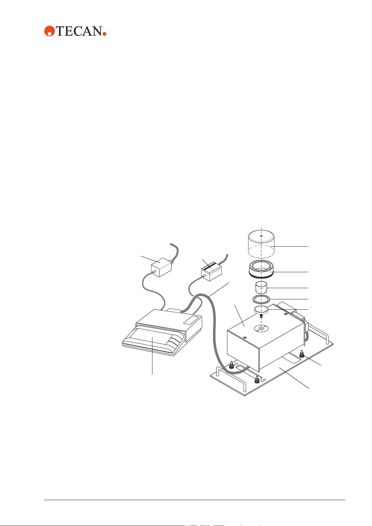
Overview The following figure provides a quick overview of both the Balance Kit and the
This chapter introduces the reader to the Balance Kit and its main components. It
contains technical data, requirements and performance data.
3.1 General Description
The Balance Kit is a set of components that are needed to adapt the Mettler
Toledo Weighing Module SAG 285/01 to the instrument so that it can be used for
the Gravimetric Test.
SAG 285/01 from Mettler Toledo. Brief descriptions are given in the sections after
the figure.
L
K
I
A
B
C
H
J
Fig. 3-1 Parts of Balance Kit + SAG285/01 (Weighing Cell and Control Unit)
Draft shield
B Ring for evaporation compensation
C Vessel
D Centering ring
E Weighing pan (Mettler)
F Foot with counternut
G Adapter plate
H Weighing cell (Mettler)
I Connection cable (Mettler)
J Control unit (Mettler)
K Connection cable LC-RS9 (Mettler)
L Power supply (Mettler)
D
E
F
G
Balance Kit Operating Manual, 393278, en, V1.0 3 - 1
Page 12
3 - Technical Data
General Description
3.1.1 Balance Kit
The following table lists the parts the Balance Kit consists of. Also refer to
Fig. 3-1, 3-1.
Tab. 3-1 Parts of the Balance Kit
Item in
Figure
A 1 Draft shield Protects the vessel (C) with the liquid to be weighed
B 1 Evaporation
C 2 Vessel Contains the liquid to be weighed during the Gravimet-
D 1 Centering ring Holds the evaporation ring (B) in place
F 1 Adapter plate Plate with two handles and positioning slots that can
G 4 Foot + counter-
Quantitiy Designation Explanation
from air drafts.
This ring is placed on the Weighing Cell (H) as shown
ring
nut
in the figure. It contains a groove that can be filled with
distilled or de-ionized water. During operation, part of
this liquid evaporates and thus increases the air
humidity under the draft shield. This, in turn, has the
effect that less liquid evaporates from the vessel during the Gravimetric Test. In this way, the accuracy of
the test results is increased indirectly.
ric Test. The vessel rests on the weighing pan (E).
be placed in the appropriate grid position on the worktable. It also has four positioning holes that allow positioning the Weighing Cell (H) properly on the plate.
The four feet are standard knurled screws with a plastic head. They are screwed to the bottom of the Weighing Cell (H) and can be used to level out the Weighing
Cell. The counternuts serves for securing the feet.
Ordering the
Balance Kit
The Balance Kit (or certain parts of it) can be ordered from Tecan or via a local
Tecan representative. For more details see section
7 “Spare Parts and Accessories”, 7-1.
Note: The Balance Kit does not comprise the Weighing Module (weighing cell +
control unit), nor are the connection cable and other accessories part of the kit.
These items must be ordered directly from Mettler Toledo AG (see next section).
3 - 2 Balance Kit Operating Manual, 393278, en, V1.0
Page 13

3.1.2 SAG 285/01
3 - Technical Data
General Description
Brief
Description
The SAG 285/01 is a product of Mettler Toledo AG and has been available since
January 2004. This SAG 285/01 consists of a Weighing Cell (H) and a separate
Control Unit (J) that are interconnected with a cable. Thanks to this separation a
higher precision and stability can be attained.
The SAG 285/01 is a substitute for the predecessor model AG 285 which
incorporated the weighing cell, the display and the operating and control elements
in one unit. Note, that this model is no longer available.
The following two tables list the parts that must be ordered directly from Mettler
Toledo:
Tab. 3-2, 3-3 lists the parts the SAG 285/01consists of.
Tab. 3-3, 3-3 lists the accessories that must be ordered separately.
See also Fig. 3-1 , 3-1.
Tab. 3-2 Weighing Module SAG 285/01
Item in
figure
H 1 Weighing Cell Is placed on the adapter plate (F) and actually weighs
J 1 Control Unit The control unit is separated from the weighing cell
I 1 Connection
Quantity Designation Explanation
the liquid in the vessel.
(H). It contains a digital display and the necessary controls that allow operating the whole Weighing Module.
Connects the Weighing Cell to the Control Unit. Please
cable 1.5 m
note that a 5 m cable is available as an option (see
below)
Ordering the
SAG 285/01 and
Accessories
L 1 Power supply This power supply unit is connected to the control unit.
Tab. 3-3 Accessories for the SAG 285/01
Item in
Figure
E 1 Weighing pan,
Quantity Designation Explanation
Carries the vessel with the liquid to be weighed.
∅ 50 mm
K 1 Cable LC-RS9 Cable with local CAN bus to RS-232 adapter that con-
nects the Control Unit to the computer.
I 1 Connection
cable 5 m
-- 1 Transport case Optional accessory that allows transporting the
Optional. Can be used instead of the 1.5 m cable to
connect the Weighing Cell to the Control Unit.
SAG 285/01.
See section 7 “Spare Parts and Accessories”, 7-1.
Balance Kit Operating Manual, 393278, en, V1.0 3 - 3
Page 14

3 - Technical Data
Technical Data
3.2 Technical Data
3.2.1 Balance Kit
Overall
Dimensions
The following figure shows the overall dimensions of the adapter plate with
installed Weighing Cell and draft shield.
t
h
a2
a1
h
a
w
l
a
Fig. 3-2 Adapter plate with weighing cell and draft shield
h
Tab. 3-4 Adapter plate (with / without weighing cell and draft shield)
Dimension Measurement [mm / in.]
Overall height with installed Weighing Cell
with draft shield
Height of adapter plate (with handles, without
h
t
h
a2
approx.
130 / 5.1
38 / 1.5
a)
Weighing Cell)
Thickness of adapter plate h
Length of adapter plate l
Width of adapter plate w
Grid positions occupied by adapter plate on
a1
a
a
w
a
6 / 0.23
339.5 / 13.4
149 / 5.9
6 grids
worktable
a) Exact value depends on the adjustment of the feet
3 - 4 Balance Kit Operating Manual, 393278, en, V1.0
Page 15

3 - Technical Data
Technical Data
Other Parts
of Kit
The following table shows the heights and diameters of the other parts of the
Balance Kit. Also see Fig. 3-1 , 3-1.
Tab. 3-5 Dimensions of Parts of Kit
Item in
figure
A Draft shield 55 / 2.2 95 / 3.7
B Evaporation ring 25 / 0.98 87 / 2.2
C Vessel 25 / 0.98 41 / 1.6
D Centering ring 3 / 0.12 62 / 2.4
F Foot 23 / 0.91 16 / 0.63
Designation Height
[mm / in.]
Diameter
[mm / in.]
Weight The Balance Kit (parts A, B, 2 x C, D, F and G) without packaging weighs approx.
1.1 kg (2.42 lb.).
3.2.2 Technical Data of SAG 285/01
For details refer to the SAG 285/01 Operating Manual from Mettler Toledo AG.
3.2.3 Supply, Connections
Balance Kit The Balance Kit contains only mechanical parts; there are no electrical
connections.
SAG285/01 The SAG 285/01 is supplied and connected as follows:
Power supply: Via a separate power supply (included in delivery) that is
connected to the Control Unit.
Interconnection between Control Unit and Weighing Cell: Connection cable
1.5 m (included in delivery) or optional 5 m cable.
Connection to computer: From Control Unit via separate LC-RS9 cable (to be
ordered separately).
Balance Kit Operating Manual, 393278, en, V1.0 3 - 5
Page 16

3 - Technical Data
Requirements
3.3 Requirements
3.3.1 Hardware Requirements
Instrument and Computer
Instrument The Balance Kit together with the SAG 285/01can be used on the following
instruments types: Freedom EVO instruments, Genesis Freedom and Genesis
Classic instruments.
Computer Hardware requirements as specified in the Instrument Software Manual that
corresponds to the installed version of the Instrument Software.
Possible interfaces for connecting the instrument and the SAG 285/01 see below.
Interfaces, Adapters
There is more than one possibility to connect the instrument and the SAG 285/01
to the computer.
Two R S-23 2
Ports
USB Ports To connect the instrument and/or the SAG 285/01 to the computer via USB ports,
If the computer has two free RS-232 ports, both the SAG 285/01 and the
instrument can be connected directly.
Note: Depending on the connectors at the instrument cable and the computer,
adequate 9 to 25-pole RS-232 adapters and / or gender changers may be
needed.
an appropriate USB to Serial converter is needed.
Recommended USB to Serial converters:
Aten UC-232A USB to RS232 Converter. Has one RS-232 connector and
plugs into a USB port on the computer.
Exsys EX-1331 USB to RS232 Converter. One RS-232 and 1 one USB
connector.
Exsys EX-1334 USB to RS-323 Converter. Has four RS-232 connectors and
plugs into a single USB port on the computer.
The above converters feature the following:
Data rate: Up to 230 Kb per second
RS-232 connectors: Male DB9
Compliant with USB Specifications V1.1
Suitable for Windows 2000 and XP
Note: A mixed connection (instrument to RS-232, SAG 285/01 via USB) is also
possible.
3 - 6 Balance Kit Operating Manual, 393278, en, V1.0
Page 17

3 - Technical Data
Requirements
Connection via
Uniport
Instrument
Software
Operating
System
If the computer has only one free RS-232 port and no USB port, the SAG 285/01
may be connected via the Uniport board, provided the following conditions are
fulfilled:
Instrument Software V4.5 or earlier is installed on the computer.
The instrument is equipped with a Uniport board.
Note:
• Apart from Genesis RMP or instruments used in customized solutions, Tecan
instruments are not normally equipped with a Uniport board.
• If possible, a separate Uniport board may be installed for the Gravimetric
Test.
• The connection via the Uniport is not supported by the Instrument Software
version V4.6 or later.
3.3.2 Software
Version V4.2 or later is required.
Note: The connection of the SAG 285/01 via Uniport is no longer supported from
Instrument Software Version 4.6 or later.
According to specifications of installed version of Instrument Software.
Drivers for
USB / RS-232
Converters
The delivery of the recommended USB to RS-232 converters includes drivers that
are suitable for Windows 2000 and Windows XP.
Balance Kit Operating Manual, 393278, en, V1.0 3 - 7
Page 18

3 - Technical Data
Requirements
3.3.3 Access Rights, Passwords
To carry out the Balance Setup function and the Gravimetric Test with the
Instrument Software you need the following access rights:
Version V4.6x or earlier: No password required.
Version V4.7 or later: From version V4.7 onwards, all users need a user
account, together with a user name and a password.
– There are several predefined user groups with different authorization
levels.
– The Balance Setup and the Gravimetric Test can be carried out by users
with SnS_Customer access rights.
Note: For detailed information about user accounts, passwords and access rights
refer to the Instrument Software Manual (for software version V4.7 or later),
section “Tecan User Administration System”.
3.3.4 Syringes and Liquid for Gravimetric Test
Syringes: 250 µl, 500 µl, 1 ml.
System liquid: Demineralized or de-ionized and degassed water. Water
temperature should correspond to ambient temperature.
Pipetting liquid: Tap water. Water temperature should correspond to ambient
temperature.
3 - 8 Balance Kit Operating Manual, 393278, en, V1.0
Page 19

4 Putting into Operation
A
Setting up the Balance Kit and the SAG 285/01
4 - Putting into Operation
Purpose of This
Chapter
This chapter describes how the Balance Kit is installed and gives instructions on
initial operation.
4.1 Setting up the Balance Kit and the SAG 285/01
4.1.1 Overview
The following figure provides an overview of the Balance Kit and the SAG 285/01
Weighing Module. For a description and the detailed specifications see section
3.1, 3-1.
L
K
I
H
A
B
C
D
E
F
J
G
Fig. 4-1 Parts of Balance Kit + SAG285/01 (Weighing Cell and Control Unit)
Draft shield
B Ring for evaporation compensation
C Vessel
D Centering ring
E Weighing pan (Mettler)
F Foot with counternut
Balance Kit Operating Manual, 393278, en, V1.0 4 - 1
G Adapter plate
H Weighing cell (Mettler)
I Connection cable (Mettler)
J Control unit (Mettler)
K Connection cable LC-RS9 (Mettler)
L Power supply (Mettler)
Page 20

4 - Putting into Operation
Setting up the Balance Kit and the SAG 285/01
4.1.2 Unpacking and Inspection
1 Unpack the Balance Kit and the SAG 285/01.
2 Ensure that no parts are missing or damaged.
3 Check whether the voltage range of the SAG 285/01 supply unit corresponds
with the local mains voltage.
4 Contact the supplier of the SAG/01 or your nearest Tecan representative if
any parts are missing or damaged.
4.1.3 For Your Safety
WARNING
Damage to the system and danger of electric shock.
Always switch the instrument and the computer off before making any electric
connections or opening the instrument’s access door.
4.1.4 Preparing the Weighing Cell
Also see Fig. 4-1 , 4-1.
H
4 Carefully place the Weighing Cell onto the adapter plate with the feet inserted
into the corresponding positioning holes.
5 Check whether the Weighing Cell is seated properly on the adapter plate and
does not wobble. If necessary adjust the cell by turning the feet until the cell is
level and stable.
6 Carefully tighten the counternuts to secure the feet when done.
7 Place the centering ring (D) on the cell and insert the cone of the weighing pan
(E) into the corresponding hole as shown in the figure.
D
E
To prepare the Weighing Cell:
1 Screw the counternuts on the
screw bolts of the feet (F)
down until the stop.
2 Screw the feet (F) into the
corresponding mounting
holes at the bottom of the
F
G
Weighing Cell (H).
3 Place the adapter plate (G)
on a the worktable in the grid
position where you want to
perform the Gravimentric test
later.
4 - 2 Balance Kit Operating Manual, 393278, en, V1.0
Page 21

Setting up the Balance Kit and the SAG 285/01
4 - Putting into Operation
4.1.5 Connecting the Weighing Cell to the Control Unit
To connect the SAG 285/01 electrically to the other parts of the system proceed
as follows (also see Fig. 4-1 , 4-1):
Weighing Cell
to Control Unit
1 Place the Control Unit (J) on a table beside the instrument.
2 Lead the connection cable (I) from the Weighing Cell (H) to the Control Unit
(J). A possible way to lay the cable is shown in Fig. 4-1 , 4-1.
3 Plug the connectors at both ends of the cable into the corresponding sockets
on the Weighing Cell and the Control Unit and fix the connectors with their
fixing screws.
Power Supply 4 Connect the power supply unit (L) to the Control Unit (J) as shown in
Fig. 4-1 , 4-1.
4.1.6 Connecting the SAG 285/01 and the Instrument to the Computer
Depending on the computer model and its interfaces there is more than one
possible way to connect the SAG 285/01 and the instrument to the computer.
Note: The Optibo board shown in the following figures is located behind the left
access door of the instrument.
Computer with
2 RS-232 Ports
If two RS-232 ports are available on the computer, both the instrument and the
Control Unit can be connected directly as shown in the following figure. This is the
simplest and least problematic arrangement.
Optibo-Board
L
RS-232
M
I
J
H
Computer
RS-232
RS-232
Fig. 4-2 Direct connection to RS-232 ports
H Weighing Cell
I Cable Weighing Cell to Control Unit
J Control Unit
Balance Kit Operating Manual, 393278, en, V1.0 4 - 3
K LC-RS9 (Control Unit to computer)
L Power supply for SAG 285/01
M Cable instrument to computer
Instrument
K
Page 22

4 - Putting into Operation
Setting up the Balance Kit and the SAG 285/01
Mixed
Connection,
RS-232 / USB
If one RS-232 port and one USB port are available on the computer, the following
configuration is also possible. Recommended connections:
Instrument: Connect the instrument cable directly to the RS-232 port of the
computer.
SAG 285/01: Connect the LC-RS9 cable (K) to the RS-232 port of the USB to
RS-232 converter (Cnv).
L
J
Computer
RS-232
USB
Cnv
RS-232
Optibo-Board
RS-232
M
I
H
Instrument
K
Fig. 4-3 Mixed connection (instrument to RS-232, Control Unit via USB)s
H Weighing Cell
I Cable Weighing Cell to Control Unit
J Control Unit
K LC-RS9 (Control Unit to computer)
L Power supply for SAG 285/01
M Cable instrument to computer
Cnv USB / RS-323 converter
Recommended converters: See sections 3.3.1, 3-6 and 7.2.2, 7-4.
4 - 4 Balance Kit Operating Manual, 393278, en, V1.0
Page 23

Setting up the Balance Kit and the SAG 285/01
4 - Putting into Operation
Computer with
USB Ports (no
RS-232)
Modern computers, particularly notebooks, often have no RS-232 ports at all, but
are equipped with two or more USB-ports. In such a case the instrument and the
Control Unit must be connected via appropriate USB to Serial converters
according to the following figure.
Note: The connection of the computer to the instrument via an USB to Serial
converter will reduce the communication speed between the instrument and the
computer. As a consequence, the execution time for the Gravimetric Test may
increase by 10 to 20 %, compared to the time it takes when the instrument is
connected to the computer directly.
Optibo-Board
L
J
K
RS-232
M
I
H
Instrument
RS-232
RS-232
Cnv
Notebook
Fig. 4-4 Connection via USB to Serial converter
H Weighing Cell
I Cable Weighing Cell to Control Unit
J Control Unit
K LC-RS9 (Control Unit to computer)
Recommended converters: See sections 3.3.1, 3-6 and 7.2.2, 7-4.
USB
L Power supply for SAG 285/01
M Cable instrument to computer
Cnv USB to serial converter
Balance Kit Operating Manual, 393278, en, V1.0 4 - 5
Page 24

4 - Putting into Operation
Setting up the Balance Kit and the SAG 285/01
Connection
via Uniport
As has been mentioned earlier (see section 3.3.1, 3-6) the SAG 285/01 may be
connected via the Uniport board under the following conditions:
Uniport board must be installed and connected to the Optibo board as shown
in the following figure.
The connection via the Uniport is only supported by Instrument Software
versions V4.5 or earlier.
Note: This configuration requires a gender changer between the LC-RS9 cable
(K) and the Uniport board. A special intermediate cable (N) that serves as a
gender changer is available from Tecan (see section 7.1.2,
Uniport
L
K
J
RS-232
7-2).
Optibo-Board
RS-232
N
M
I
H
Computer
RS-232
Fig. 4-5 Connection via the Uniport
H Weighing Cell
I Cable Weighing Cell to Control Unit
J Control Unit
K LC-RS9 (Control Unit to Uniport)
L Power supply for SAG 285/01
M Cable instrument to computer
N Intermediate cable between LC-RS9
Instrument
and Uniport (gender changer)
Procedure To connect the SAG 285/01 and the instrument to the computer:
1 Decide which of the following connection methods is suitable in your case:
– Direct connection to two RS-232 ports (see Fig. 4-2 , 4-3).
– Mixed connection, instrument to RS-232 and SAG 285/01 via a USB to
Serial converter (see Fig. 4-3 , 4-4).
– Connection via USB to Serial converter (see Fig. 4-4 , 4-5)
– Connection of SAG 285/01 via Uniport (see Fig. 4-5 , 4-6).
2 Connect the units together.
3 If you use a USB to Serial converter you must also install the appropriate
driver software on the computer. Follow the instructions provided by the
supplier of the converter.
4 Check your installation.
4 - 6 Balance Kit Operating Manual, 393278, en, V1.0
Page 25

Setting up the Balance Kit and the SAG 285/01
A
4 - Putting into Operation
4.1.7 Set Communication Protocol and Balance Parameters
Next you must set up the following:
Communications protocol
Balance parameters
Communication
Protocol
The communication protocol can be adapted by means of the three rotary
switches located inside the protocol converter of the LC-RS9 cable (over which
the Control Unit is connected to the computer).
ABC
Fig. 4-6 Protocol converter in LC/RS 9
cable
D
Peripheral selection
B Baudrate selection
C Bit/Par/HS selection
D Cover (opened)
1 Open the cover of the protocol converter.
2 Set the rotary switches (A), (B) and (C) according to the following table.
3 Close the cover.
Tab. 4-1 Setting of Communication Protocol
Switch Set to position Comment
A 0 Peripheral = Host
B 3 Baudrate = 2400 Baud
C 0 7 bits, even parity
Balance
Parameters
Next, the balance parameters must be set. For detailed information consult the
Operating Manual of the SAG 285/01.
To set the balance parameters:
1 If not done yet, connect the SAG 285/01 to the mains via the power supply
unit and switch the balance on.
2 Set the balance parameters according to the following table and store them
(except the “Reset” parameter !).
1/10 d
Cal
3 Use the 1/10 d key of the Control unit to set the
display to 2 decimal places (1/100 g).
4 Check your settings.
Balance Kit Operating Manual, 393278, en, V1.0 4 - 7
Page 26

4 - Putting into Operation
Setting up the Balance Kit and the SAG 285/01
Tab. 4-2 Required settings of balance parameters
Property Set to Comment
Vibration adapter 2 Medium weighing speed
Weighing process adapter 1 Suitable for small quantities
Reproducibility Std Standard reproducibility
Weighing unit 1 unit 1 mg Both weighing units must be mg
Weighing unit 2 unit 2 mg
Automatic zero correction az. off No automatic zero correction
Automatic off aoff - No automatic switch off
Start mode qu start Quick start. No display check at
startup.
ATTENTION
Do not reset the parameters unnecessarily, otherwise you will have to set them
again!
4.1.8 Balance Setup with the Instrument Software
Purpose The purpose of this setup is to establish the proper communication with the
SAG 285/01.
Nomenclature The Instrument Software uses the term “Balance” for the Weighing Module,
regardless of whether the Weighing Cell and the Control Unit are separated or
incorporated in the same device.
Required for
the Setup
To run the setup procedure you need the following:
Instrument Software Manual that corresponds to the installed version.
– A PDF-file of the manual is stored on the installation CD of the Instrument
Software.
– Operating Manual of the SAG 285/01 Weighing Module.
If version V4.7 or later is installed on the computer you need a user account
with a user name and a password.
– Required access rights: SnS_Customer access level or higher.
– If necessary turn to the system administrator for an appropriate user
account and the necessary access rights.
Procedure The procedure varies slightly, depending on the version of the installed Instrument
Software: Always follow the instructions provided in the Instrument Software
Manual and/or the SAG 285 Operating Manual.
To perform the Balance Setup:
1 Switch on the computer and the SAG 285/01.
2 Tare the Weighing Cell (see SAG 285 Operating Manual).
4 - 8 Balance Kit Operating Manual, 393278, en, V1.0
Page 27

3 Switch the instrument on.
4 From the Windows task bar start the Setup & Service software (which is part
of the Instrument Software package) with
Start > Programs > Instrument Software > Setup & Service
5 If the Instrument Software V4.7 or later is installed:
– You will be prompted to log in with your user name and password.
– If you log in for the first time you must change the password.
6 Call up the function Liquid System > Balance. Follow the instructions in the
Instrument Software Manual to set up and test the communication with the
balance.
4.1.9 Loading the Worktable Map
Setting up the Balance Kit and the SAG 285/01
4 - Putting into Operation
General
Procedure
In order to perform the Gravimetric Test you must load a suitable worktable map.
Refer to the Instrument Software Manual for details.
1 Call up the Setup & Service software function System > Load Worktable.
2 Choose the appropriate worktable map for the Gravimetric Test (see
remarks below).
3 If necessary, store the worktable map under a new name and use the
Worktable Complete Editor to adapt it to your needs.
Remarks
Instrument
Software V4.7
or later
Earlier Versions
of Instrument
Software
The Instrument Software V4.7 or later includes a worktable map that corresponds
to the adapter plate for the SAG 285/01 Weighing Cell. If necessary, you can
modify this map according to your needs with the Worktable Complete Editor.
If version V4.6 or earlier is used, you will probably not find a worktable map that
corresponds to the adapter plate for the SAG 285/01, but one that was suitable for
the predecessor model (for AG 285/245 and other models).
This previous adapter plate was 10 grid positions wide, whereas the SAG 285/01
plate occupies 6 grid positions. Moreover, the SAG 285/01 adapter plate (with
Weighing Cell and draft shield) is approx. 5 mm higher than the previous model.
Workaround: However, you can still use the old worktable map if you place the SAG 285/01
adapter plate into a grid position that corresponds to the middle of the old map.
Example: If the left grid position for the old adapter plate is 2, then place the
SAG 285/01 adapter plate in grid position 4.
Generally speaking: Left grid position of SAG 285/01 adapter plate = Left grid
position of AG 285/245 plate + 2.
Professional
Solution
A better solution is to store the existing worktable map under a new name and to
use the Worktable Complete Editor to adapt the following parameters:
Width of adapter plate: 6 grid positions
Overall height: 130 mm (corresponds to height of adapter plate with installed
Weighing Cell and draft shield, also see section 3.2.2, 3-5).
Balance Kit Operating Manual, 393278, en, V1.0 4 - 9
Page 28

4 - Putting into Operation
Setting up the Balance Kit and the SAG 285/01
4.1.10 Getting Ready for the Gravimetric Test
Now the last steps before the Gravimetric Test can be carried out.
A
t
i
l
l
e
d
W
a
D
i
s
t
e
r
C
E
B
H
Fig. 4-7 Getting ready for the Gravimentric Test
Procedure To make the installation ready for the Gravimetric Test:
1 If not done yet, place the adapter plate (G) with the installed Weighing Cell (H)
on the worktable in the grid position that corresponds to the worktable map.
2 Place the evaporation ring (B) on the Weighing Cell.
3 Place the vessel (C) on the weighing pan (E).
4 Carefully fill the evaporation ring with distilled or de-ionized water until the ring
is about half-full.
B
G
ATTENTION
Damage to Weighing Cell possible if liquid is spilled over the cell.
Be careful not to fill up the ring too much, so that you can safely remove it
from or place it on the Weighing Cell without spilling any liquid.
Wipe up any spilled liquid with a soft lint-free cloth.
5 Cover the evaporation ring and the parts inside it with the draft shield (A).
The Gravimetric Test can now be carried out.
4 - 10 Balance Kit Operating Manual, 393278, en, V1.0
Page 29

5 Operation
A
Operating and Display Elements
5 - Operation
Purpose of This
Chapter
This chapter briefly explains the operating elements and gives instructions on how
to carry out the Gravimetric Test.
5.1 Operating and Display Elements
A
B
E
Operating
Elements
C
Fig. 5-1 Operating elements for Gravimetric Test
Computer display
B SAG 285 Control Unit
C Keyboard (not directly visible)
The Balance Kit itself has no operating and display elements of its own. Most of
the operating and display elements needed for the Gravimetric Test are shown in
D
D Mouse
E Power switch of instrument (not
directly visible)
the above figure.
Power Switches The location of the power switches of the computer and the instrument depend on
the models used to run the Gravimetric Test.
Balance Kit Operating Manual, 393278, en, V1.0 5 - 1
Page 30

5 - Operation
Gravimetric Test
5.2 Gravimetric Test
5.2.1 Safety Instructions
WARNING
Automatically moving parts.
Injuries (crushing, piercing) possible, if the safety covers are not in place.
Before starting the Gravimetric Test, check if the safety panel of the
instrument is closed.
Never run the test without covers.
WARNING
Depending on the application run on the instrument, biohazardous, poisonous or
radioactive materials may have been used.
Make sure you protect your body with adequate protective gear, such as
goggles, gloves and protective clothing before starting the Gravimetric Test.
5.2.2 Gravimetric Test
It is assumed that you have carried out all steps described in chapter “Putting into
Operation” and that the test can now be carried out.
Required
Documentation
Procedure To perform the Gravimetric Test:
Make sure you have the following documents handy:
Instrument Software Manual that corresponds to the installed version of the
Instrument Software.
Operating Manual of SAG 285 Weighing Module.
Operating Manual of the instrument on which you wish to run the test.
1 From the main menu of the Setup & Service software, start the test with
Liquid System > Gravimetric Test.
2 Follow the instructions provided on screen and in the Instrument Software
Manual.
Evaluation of
Results
5 - 2 Balance Kit Operating Manual, 393278, en, V1.0
See Instrument Software Manual.
Page 31

6 Troubleshooting
6 - Troubleshooting
Troubleshooting Table
Purpose of This
Chapter
Trouble-
shooting by
the Operator
This chapter helps to resume operation after a minor problem has occurred with
the Balance Kit or the SAG 285/01 when used for Gravimetric Test and its
preparation. It lists possible problems, their probable cause and suggests how to
remedy the problems.
6.1 Troubleshooting Table
The following table lists problems and errors and gives hints on how to eliminate
them.
Tab. 6-1 Troubleshooting table
Problem / error Possible cause Corrective measures
Weighing Cell wobbles Feet not adjusted
properly
No display on Control
Unit
Control Unit does not
react to changes in
weight on Weighing Cell
Control Unit not connected to mains
Control Unit not connected to Weighing
Cell
Level out the Weighing Cell by adjusting the
feet and secure with counternuts.
Connect the control unit via the power
supply unit.
Check connection between units and connect properly.
Values shown on computer screen do not correspond to those shown on
display of Control Unit.
Control Unit not connected to computer
Control Unit not set up
properly
Wrong communication
protocol
Uniport: Connection
via Uniport not correct
Connection via USB:
RS-232 to USB adapters to slow
USB adapters not
installed properly or
drivers not compatible with operating system
Check connection to computer.
Repeat setup.
Check the settings of the protocol converter
in the LC-RS9 cable.
Check the following connections:
• SAG 285/01 Control Unit to Uniport
• Uniport to Optibo board
Use recommended USB adapters.
Install adapters correctly according to
instructions provided by the supplier. Make
sure the correct drivers are installed.
Balance Kit Operating Manual, 393278, en, V1.0 6 - 1
Page 32

6 - Troubleshooting
Troubleshooting Table
Tab. 6-1 Troubleshooting table (cont.)
Problem / error Possible cause Corrective measures
During Gravimetric Test
the LiHa is not moved to
the correct position above
the Weighing Cell
1 USB, 1 RS-232 port:
Connections mixed
up.
Balance Setup function in Setup & Service SW carried out
incorrectly
Grid position of
adapter plate does not
correspond to worktable map
Wrong worktable map
loaded
Connect instrument to RS-232 port and
Control Unit to USB.
Repeat Balance Setup and test if Control
Unit communicates properly with Instrument
Software.
Place the adapter plate in the correct grid
position.
Load the correct worktable map.
6 - 2 Balance Kit Operating Manual, 393278, en, V1.0
Page 33

7 Spare Parts and Accessories
A
7 - Spare Parts and Accessories
Purpose of This
Chapter
How to Find
Parts
How to
Order Parts
Overview
This chapter lists the parts and accessories used in connection with the Balance
Kit and the Weighing Module SAG 285/01, including the ordering information.
Identify the parts from the following figure and look up the ordering information in
the tables later in this chapter.
Spare parts must be ordered from the corresponding manufacturer or from its
nearest representative:
Balance Kit: From Tecan. Addresses see section 8 “Customer Support”, 8-1
Parts and accessories for the SAG 285/01: Directly from Mettler Toledo.
USB to Serial Converters: From manufacturer or specialized distributor.
Note: This chapter only contains parts that can be replaced by the operator him/
herself. If you want to order Tecan parts that are not listed here, please contact
the Tecan Customer Support.
A
L
K
B
I
C
H
J
Fig. 7-1 Parts of Balance Kit + SAG285/01 (Weighing Cell and Control Unit))
Draft shield
B Ring for evaporation compensation
C Vessel
D Centering ring
E Weighing pan (Mettler)
F Foot with counternut
G Adapter plate
H Weighing cell (Mettler)
I Connection cable (Mettler)
J Control unit (Mettler)
K Connection cable LC-RS9 (Mettler)
L Power supply (Mettler)
D
E
F
G
Balance Kit Operating Manual, 393278, en, V1.0 7 - 1
Page 34

7 - Spare Parts and Accessories
Tecan Spare Parts and Accessories
7.1 Tecan Spare Parts and Accessories
The parts listed in this section must be ordered from Tecan or a Tecan
representative.
7.1.1 Balance Kit
Entire Kit
Tab. 7-1 Balance Kit for SAG 285/01
Designation Tecan Part No.
Balance Kit for SAG 285/01, including:
• 1 Draft shield (A)
• 1 Evaporation ring (B)
• 2 Vessels (C)
• 1 Centering ring (D)
• 4 Feet with counternuts (F)
• 1 Adapter plate (G)
Spare Parts The following parts of the Balance Kit are available as spare parts.
Tab. 7-2 Spare parts of Balance Kit
Designation Tecan Part No.
Draft shield (A) 619 020
T
619 014
7.1.2 Uniport
Note: Remember that the connection via Uniport is not supported by the
Instrument Software V4.6 or later.
Tab. 7-3 Uniport
Designation Tecan Part No.
Uniport board 619 004
Intermediate cable between Uniport and LC-RS9 cable 619 013
7 - 2 Balance Kit Operating Manual, 393278, en, V1.0
Page 35

7.1.3 Instrument Software
The Instrument Software is delivered on a CD-ROM (or a set of diskettes).
Note: The CD-ROM also contains a PDF-file of the associated Instrument
Software Manual.
Tab. 7-4 Instrument Software
Version Used for Tecan Part No.
V4.2 Genesis Classic 615 018
V4.3 Genesis Freedom
V4.5 Genesis Freedom & Classic 615 018
V4.6 Freedom EVO, Genesis Freedom & Classic 615 018
7 - Spare Parts and Accessories
Parts from Other Manufactures
a)
615 093
a)
Weighing
Module
To be Ordered
Separately
V4.7 Freedom EVO, EVOlyzer, Genesis Freedom &
Classic (except RMP)
a) Special version that was validated for Genesis Freedom only
7.2 Parts from Other Manufactures
7.2.1 Weighing Module
The Weighing Module must be ordered from Mettler Toledo.
Tab. 7-5 Balance Kit for SAG 285/01
Designation Mettler Part No.
Weighing Module SAG 285/01, including:
• 1 Weighing Cell (H)
• 1 Control Unit (J)
• 1 Cable Control Unit ↔ Weighing Cell, 1.5 m (I)
• 1 Power supply (L)
The following parts are not included in the SAG 285/01 and must be ordered
separately from Mettler Toledo:
615 018
SAG 285/01
Tab. 7-6 Spare parts of Balance Kit
Designation Mettler Part No.
Weighing pan, diameter 50 mm (E) 238 472
Cable LC-RS 9 (K) 229 065
Cable Control Unit ↔ Weighing Cell, 5 m (I) 210 688
Transport case (optional) 238 852
Balance Kit Operating Manual, 393278, en, V1.0 7 - 3
Page 36

7 - Spare Parts and Accessories
Parts from Other Manufactures
7.2.2 USB to RS-232 Converters
These converters must be ordered from a specialized distributor or directly from
the manufacturer.
Tab. 7-7 USB to Serial Adapters
Manufacturer Designation Part No.
Aten International
Company Ltd.
www.aten.com
Exsys Vertriebs GmbH
www.exsys.ch
www.exsys.de
USB to RS-232 Converter
(1 USB to 1 RS-232 port)
USB to RS-232 Converter
(1 USB to 1 RS-232 port)
USB to RS-232 Converter
(1 USB to 4 RS232 port)
UC-232A
EX-1331
EX-1334
7 - 4 Balance Kit Operating Manual, 393278, en, V1.0
Page 37

8 Customer Support
8 - Customer Support
Purpose of This
Chapter
This chapter informs you how to contact us in case help is needed. It lists
addresses and telephone numbers of the manufacturer’s representatives.
How to get Help Tecan and its representatives maintain a fully trained staff of technical specialists
around the world. For any technical question, contact your system integrator or
nearest Tecan representative.
Addresses Contact your local distributor or one of the addresses below.
Also see our homepage on the web: www.tecan.com
Country/Region Address Telephone/Telefax/E-mail
Switzerland Tecan Sales Switzerland AGSeestrasse 103
CH-8708 Männedorf
Switzerland
Asia Tecan Asia (Pte) Ltd. 80, Marine Parade
#13-04
Singapore 449 269
Austria Tecan Austria GmbH Untersbergstrasse 1a
5082 Grödig / Salzburg
Belgium Tecan Benelux B.V.B.A. Vaartdijk 55
B-2800 Mechelen
Telephone
Te le f ax
E-mail
Telephone
Te le f ax
E-mail
Telephone
Te le f ax
E-mail
Telephone
Te le f ax
E-mail
+41/1 922 82 82
+41/1 922 84 84
helpdesk-ch@tecan.com
+65 644 41 886
+65 644 41 836
tecan@tecan.com.sg
+43 62 46 89 33 444
+43 62 46 89 33 39
helpdesk-at@tecan.com
+32 15 42 13 19
+32 15 42 16 12
tecan-be@tecan.com
France Tecan France S.A. Parc d’Activités de Pissaloup
Bâtiment Hermes II
27, Rue Edouard Branly
F-78190 Trappes
Germany Tecan Deutschland GmbH Theodor-Storm-Strasse 17
D-74564 Crailsheim
Great Britain Tecan UK Theale Court
11-13 High Street
Theale, UK-Reading
Berkshire RG7 5AH
Italy Tecan Italia, S.r.l. Via Fratelli Cerci
Palazzo Bernini
Centro Direzionale Milano 2
I-20090 Sergate (Mi)
Japan Tecan (Japan) Co. Ltd. Meiji Seimei Fuchu Building
10F
1-40, Miyamachi
Fuchu City
Tokyo
Telephone
Te le f ax
E-mail
Telephone
Te le f ax
E-mail
Telephone
Te le f ax
E-mail
Telephone
Te le f ax
E-mail
Telephone
Te le f ax
E-mail
+33 1 30 68 81 50
+33 1 30 68 98 13
helpdesk-fr@tecan.com
+49 7951 94 170
+49 7951 50 38
helpdesk-de@tecan.com
+44 118 930 0300
+44 118 930 5671
helpdesk-uk@tecan.com
+39 02 215 21 28
+39 02 215 97 441
helpdesk-it@tecan.com
+81 66 30 58 511
+81 42 33 40 401
helpdesk-jp@tecan.com
Balance Kit, Operating Manual, 393278, en, V1.0 8 - 1
Page 38

8 - Customer Support
Country/Region Address Telephone/Telefax/E-mail
Netherlands Tecan Benelux B.V.B.A. Industrieweg 30
NL-4283 Giessen
Scandinavia Tecan Nordic AB Box 208
SE-43123 Mölndal
Sweden
Spain Tecan Ibérica
Instrumentación S.L.
Sabino de Arana
32
E-08028 Barcelona
USA Tecan U.S. P.O. Box 13953
Research Triangle Park
NC 27709
USA Tecan Systems Inc.
(formerly Cavro)
2450 Zanker Road
San Jose
CA 95131
Telephone
Te le f ax
E-mail
Telephone
Te le f ax
E-mail
Telephone
Te le f ax
E-mail
Telephone
Te le f ax
E-mail
Telephone
Te le f ax
E-mail
+31 018 34 48 174
+31 018 34 48 067
tecan-nl@tecan.com
+46 31 75 44 000
+46 31 75 44 010
tecan.nordic@tecan.com
+34 93 490 01 74
+34 94 411 24 07
tecanbcn@terra.es
+1 919 361 5200
+1 919 361 5201
helpdesk-us@tecan.com
+1 408 953 31 00
+1 408 953 31 07
tecansystemsinfo@tecan.com
8 - 2 Balance Kit, Operating Manual, 393278, en, V1.0
Page 39

9 Glossary
9 - Glossary
Purpose of This
Chapter
Glossary Balance
This chapter contains a glossary to explain terms and expressions used in this
Operating Manual.
– Instrument for determining the weight of something, scales.
– Setup function of the Instrument Software in which the communication of
the balance with the instrument is established so that the balance can be
used for the Gravimetric Test.
Balance Setup
Steps to be performed to adapt the balance parameters to the requirements of
an application (range, units, precision, etc.).
Communication Protocol
A standard set of rules that define how computers communicate with other
computers or devices. In order that connected computers and devices
“understand” each other they must use the same protocol.
Controller Area Network (CAN)
Network used to exchange information between connected devices.
Information is sent/received in the form of “messages” via a high-speed bus,
the CAN-bus. Each “message” consists of a “label” that is unique throughout
the network and a “data part”. From the label, the receiving device knows what
kind of information the data part contains.
Gravimetric Test
Test function implemented in the Instrument Software with which the precision
and the accuracy of the liquid transfer can be checked with the aid of an
external precision balance.
Instrument Software
Software package consisting of several interacting software programs (Setup
& Service, NPS Quick Test, Worktable Editor and Communication driver).
Protocol
See Communication Protocol
SAG 285/01
Precision balance, manufactured by Mettler Toledo, consisting of a Weighing
Cell and a separate Control unit.
Setup & Service Software
Part of the Instrument Software package with which the devices and options
installed on or connected to the instrument can be set up and tested.
Uniport
Interface board (used in Genesis RMP) with 4 RS-232 ports over which up to
4 external devices can be connected to the CAN bus of the instrument. Note
that the connection via Uniport is no longer supported by Instrument Software
V4.6 or later.
Universal Serial Bus (USB)
An external bus standard that supports high data transfer rates. A single USB
port can be used to connect up to 127peripherals of various sorts (e.g. mice,
modems, keyboards etc.). USB also supports Plug and Play installation.
Balance Kit Operating Manual, 393278, en, V1.0 9 - 1
Page 40

9 - Glossary
Worktable
The surface of the instrument on which various objects (carriers, tube racks,
wash stations etc.) are arranged.
Worktable Complete Editor
Graphical editor that allows creating, modifying and deleting worktable maps.
Worktable Map
A graphical representation of the worktable and the objects arranged on it.
The parameters of these objects (e.g. grid position, width, height) are needed
by the software which must know where they are placed. They also serve to
avoid collisions with moving arms, e.g. RoMa or LiHa.
9 - 2 Balance Kit Operating Manual, 393278, en, V1.0
 Loading...