


V ideo Cassette R eco rder
MV-8080G
Service Manual
NO.289C3090
MV-8080G_1 Cover 97.12.10, 20:35Page 1 Adobe PageMaker 6.0J/PPC

Quick Reference of Specific Parts List
(Latest upgrade list Dec. ’97)
The parts No. of Deck Mechanisms, Face Plate Ass’y and Video Circuit Boards for MV-8080G.
CABINET & CHASSIS
Ref. No. Part No. Description
1 59311
2 59277
21 22329340 FACE PLATE ASS’Y (MV-8080G)
32 26021610 POWER CORD
35R93C0 UPPER VIDEO CIRCUIT BOARD (MV-8080G)
36 MAIN CIRCUIT BOARD (WITH POWER SECTION)
(IC1701) (119412400) (IC,CXP88132-185Q)
37 HEAD CIRCUIT BOARD
38 SCART CIRCUIT BOARD
35R94C0
39 MAIN CIRCUIT BOARD (WITH TUNER)
(ET2A01) (104307420) (ET-TMLG1-103A)
(IC2701) (119413400) (IC,CXP87360-120Q)
(IC2703*) (113112B00) (IC,AT24C02-10PC)
40 HEAD CIRCUIT BOARD
For details, refer to pages 26 to last page.
*The IC ROM settings vary for each model, so please specify the model you are using when ordering replace-
ment IC-ROM 2703 parts.
UPPER DECK MECHANISM (TN6500-116M) FOR P.B. ONLY
LOWER DECK MECHANISM (TN6500-105M) FOR REC/PB
LOWER VIDEO CIRCUIT BOARD (MV-8080G) LOWER DECK
ACCESSORIES
Ref. No. Part No. Description
1 1080738H0 REMOTE CONTROLLER, RC-738
2 28529280 IN-BOX MV-8080G
3 28939060 OWNER'S MANUAL KIT MV-8080G
MV-8080G_1_Cover2 97.12.10, 20:38Page 2 Adobe PageMaker 6.0J/PPC

CONTENTS
MAINTENANCE PRECAUTIONS.........................................................................2
ELECTRICAL ADJUSTMENT..............................................................................5
1. PLAYBACK SWITCHING POINT ADJUSTMENT .........................................................................................5
MECHANICAL ADJUSTMENT ............................................................................6
DECK ADJUSTMENT POINTS ...........................................................................................................................6
1. MECHANISM CONTROL ..............................................................................................................................7
2. ADJUSTMENT OF BT TORQUE IN PLAY MODE ........................................................................................8
3. AUDIO/CTL HEAD.........................................................................................................................................9
4. TAPE TRANSPORT SYSTEM CHECKS AND ADJUSTMENT.....................................................................9
5. INTERCHANGEABILITY ADJUSTMENT ....................................................................................................11
6. RG POST HEIGHT ADJUSTMENT ..............................................................................................................14
7. FRONT LOADING ASSEMBLY ATTACHMENT...........................................................................................15
PERIODIC MAINTENANCE ..............................................................................................................................16
SERVICING DIAGRAM AND PARTS LIST ....................................................... 18
1. EXPLODED VIEW OF THE CASSETTE DECK MECHANISM ...................................................................18
2. BLOCK DIAGRAM .......................................................................................................................................22
3. TERMINOLOGY REFERENCES.................................................................................................................23
4. SCHEMATIC DIAGRAM .........................................................................................................Separate Sheet
5. IC, TRANSISTOR LEAD IDENTIFICATION ................................................................................................25
6. UPPER CABINET EXPLODED VIEW (DECK UNIT 1) ...............................................................................26
LOWER CABINET EXPLODED VIEW (DECK UNIT 2)...............................................................................27
7. PARTS LIST FOR CABINET & CHASSIS ...................................................................................................28
8. PC BOARD ASS'Y (UPPER MAIN) PARTS LOCATION.............................................................................29
PC BOARD ASS'Y (LOWER MAIN) PARTS LOCATION............................................................................31
9. PC BOARD ASS'Y (UPPER MAIN) PARTS LIST .......................................................................................33
10. PC BOARD ASS'Y (HEAD 1, 2) PARTS LIST.............................................................................................41
11. PC BOARD ASS'Y (HEAD 1, 2) PARTS LOCATION..................................................................................41
12. PC BOARD ASS'Y (SCART) PARTS LIST..................................................................................................42
13. PC BOARD ASS'Y (SCART) PARTS LOCATION.......................................................................................42
14. PC BOARD ASS'Y (LOWER MAIN) PARTS LIST.......................................................................................43
TABLE OF IC PIN VOLTAGE ......................................................................................................................52
1
MV-8080G_2 Con(1) 97.12.10, 20:40Page 1 Adobe PageMaker 6.0J/PPC
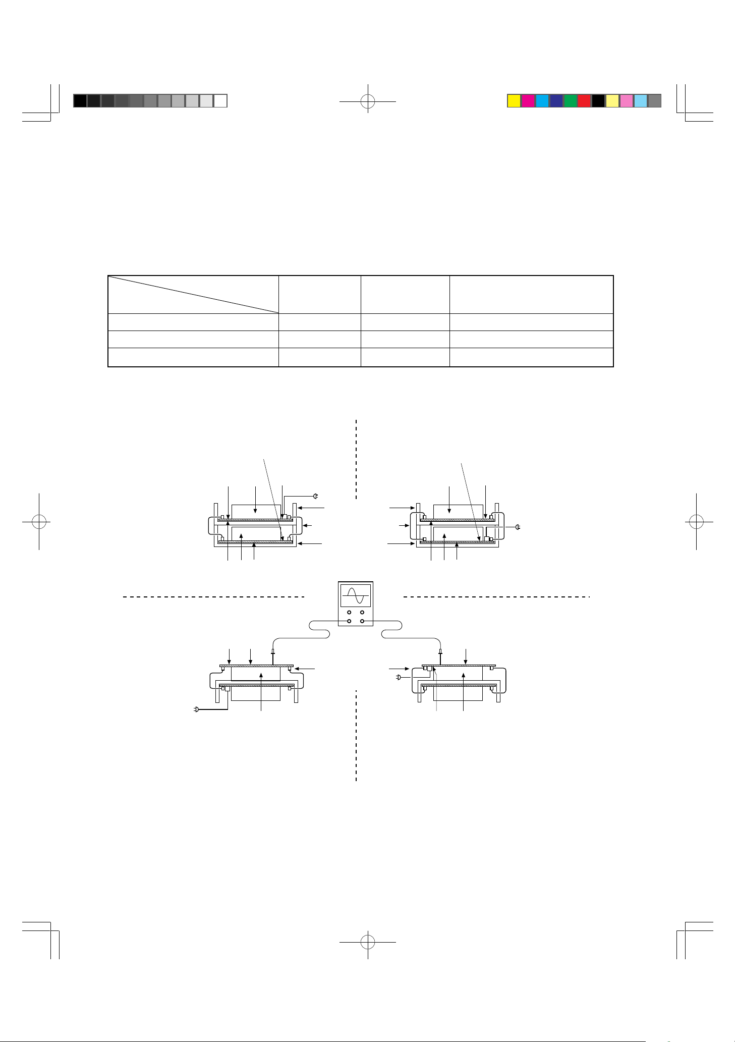
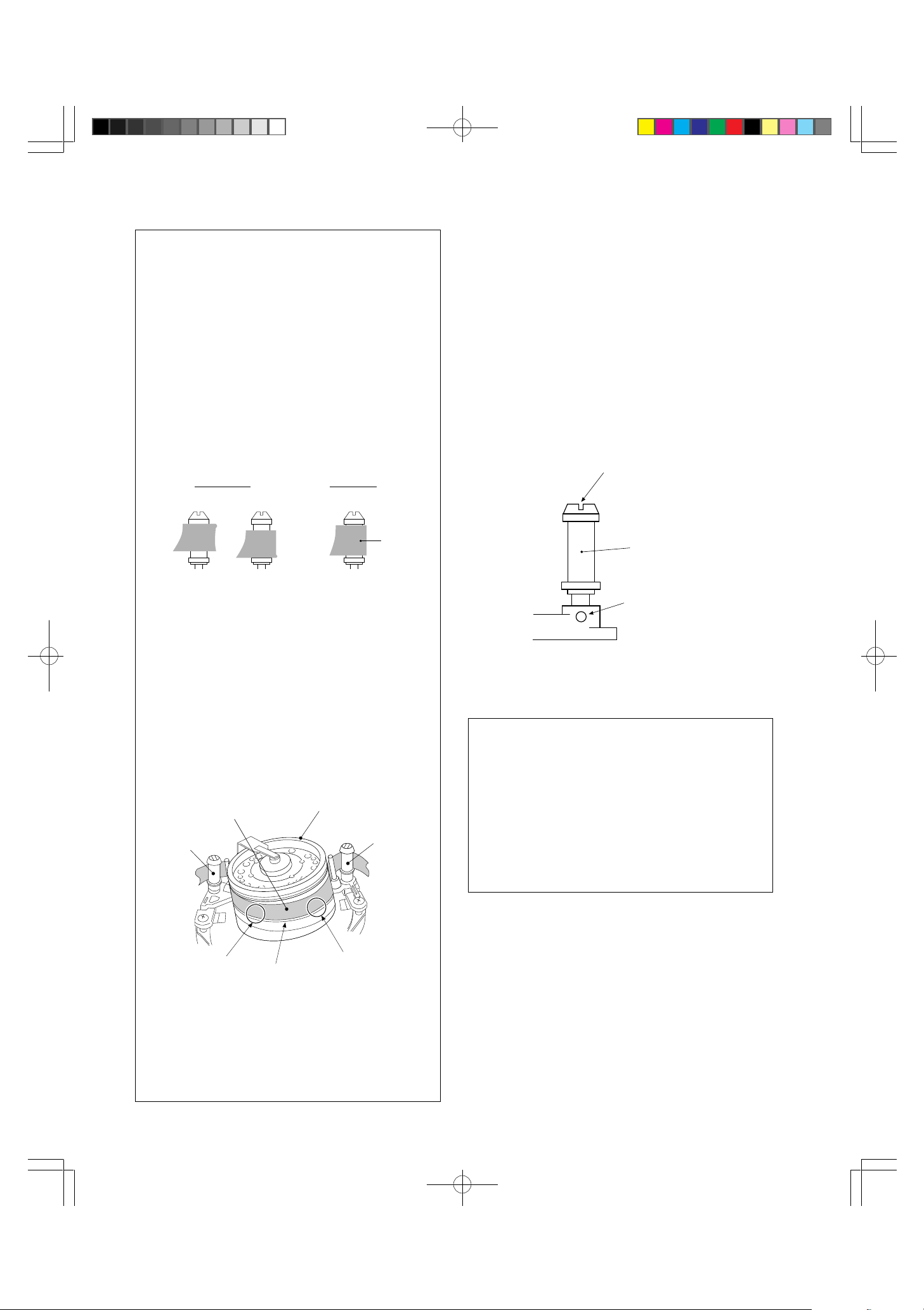
MAINTENANCE PRECAUTIONS
Since this model is a twin-deck system, some of the items to be adjusted during maintenance can be hard to
reach. (These parts are marked with an ¾ in the table below.)
:Serviceable item
○
:Difficult
#
¾ :Cannot be serviced
Position
of the Deck Unit
Items 3, 5, 6, 7 and 8 in the table above cannot be serviced in their current positions. To service these
parts, move the parts marked ¾ to those marked
mechanism and Main PCB). in the table. After testing that the serviced items work, replace the Deck Unit in its
original position.
Maintenance
Upper 1
Lower 4
External 7
Pattern (A) Original Position
4
1
Deck Unit 1
Deck Unit 2
356
()
ELEC. ADJ. MECHA. ADJ. Treatment of the solder side
SWing Point e.t.c.
○
○
or
○
#
on the Deck Unit (a single deck VCR or VCP, including Deck
○
DECK Adj. on the Main PCB
2
○
3 ¾
5 ¾ 6 ¾
8 ¾ 9
Pattern (B) Upper and Lower Deck Unit
Positions Inverted
4
12
AC IN
Upper Position
Flexible Wire Harness
Lower Position
¾
SYNCHROSCOPE
3
()
12
Deck Unit 2
AC IN
Deck Unit 1
Cannot be serviced.56
¾
○
99
7
Deck Unit 2
Deck Unit 1
AC IN
¾ Cannot be
8
serviced.
Pattern (C) External Position (Upside Down)
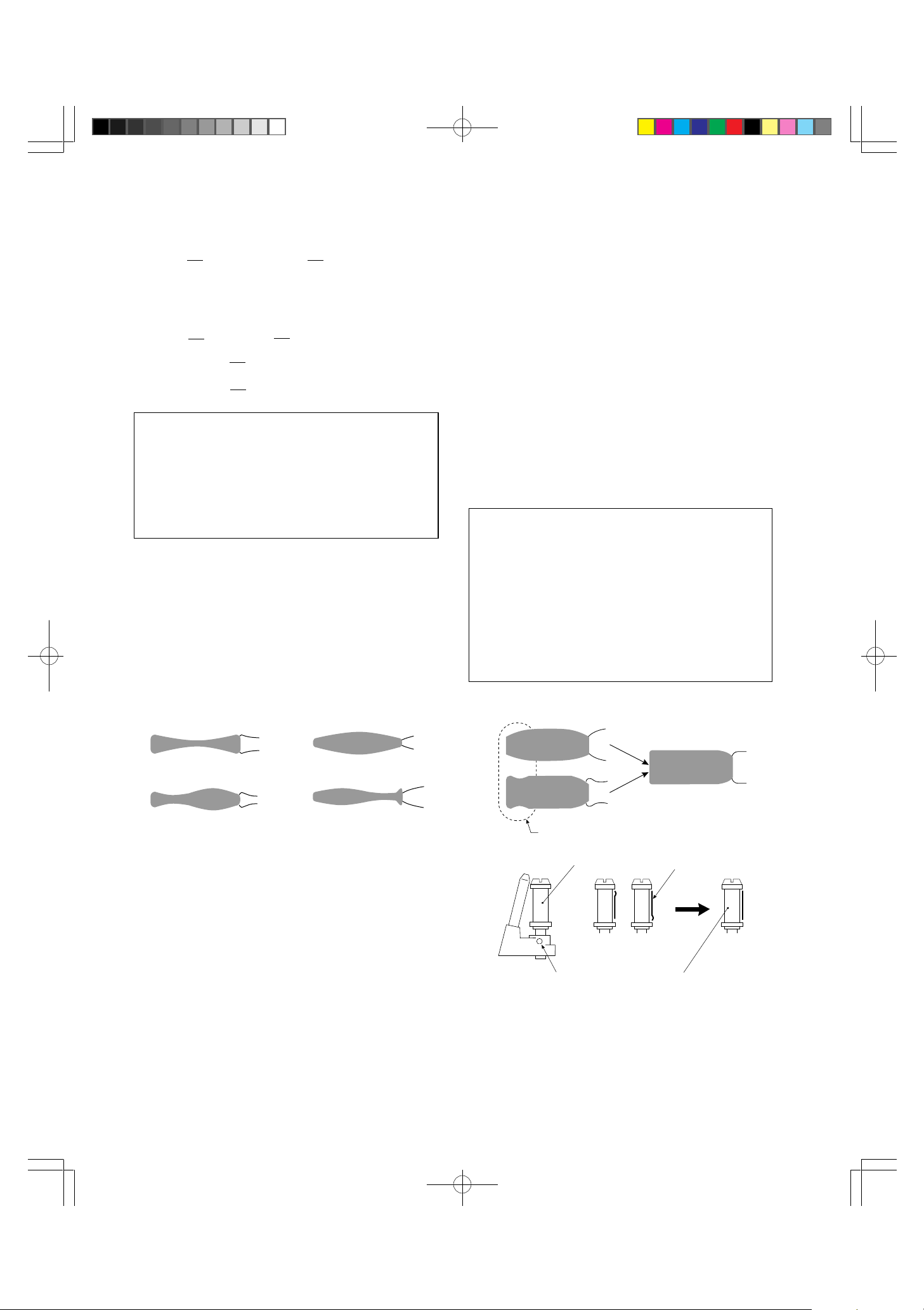
Operation cannot be tested with the deck mechanism alone.Temporarily assemble the mechanism with the Main PCB
*
to test the mechanism.
To test Pattern (B), remove the Flexible Wire Harness, then exchange the Deck Mechanism Unit 2 with Deck
Mechanism Unit 1 and reconnect the parts.
To test Patterns (C) and (D), remove the Flexible Wire Harness, then the Deck Mechanism and Main PCB (in this
order) from the Chassis. Then temporarily assemble the removed Main PCB and Deck Mechanism and reconnect
the parts. To do this, fix the two spacers of the Deck Mechanism to the back of the Main PCB with screws.
External Position
Pattern (D) External Position (Upside Down)
2
AC IN
#
7
8
¾
Deck Unit 1
Deck Unit 2
MV-8080G_3(2~4) 97.12.10, 20:41Page 2 Adobe PageMaker 6.0J/PPC
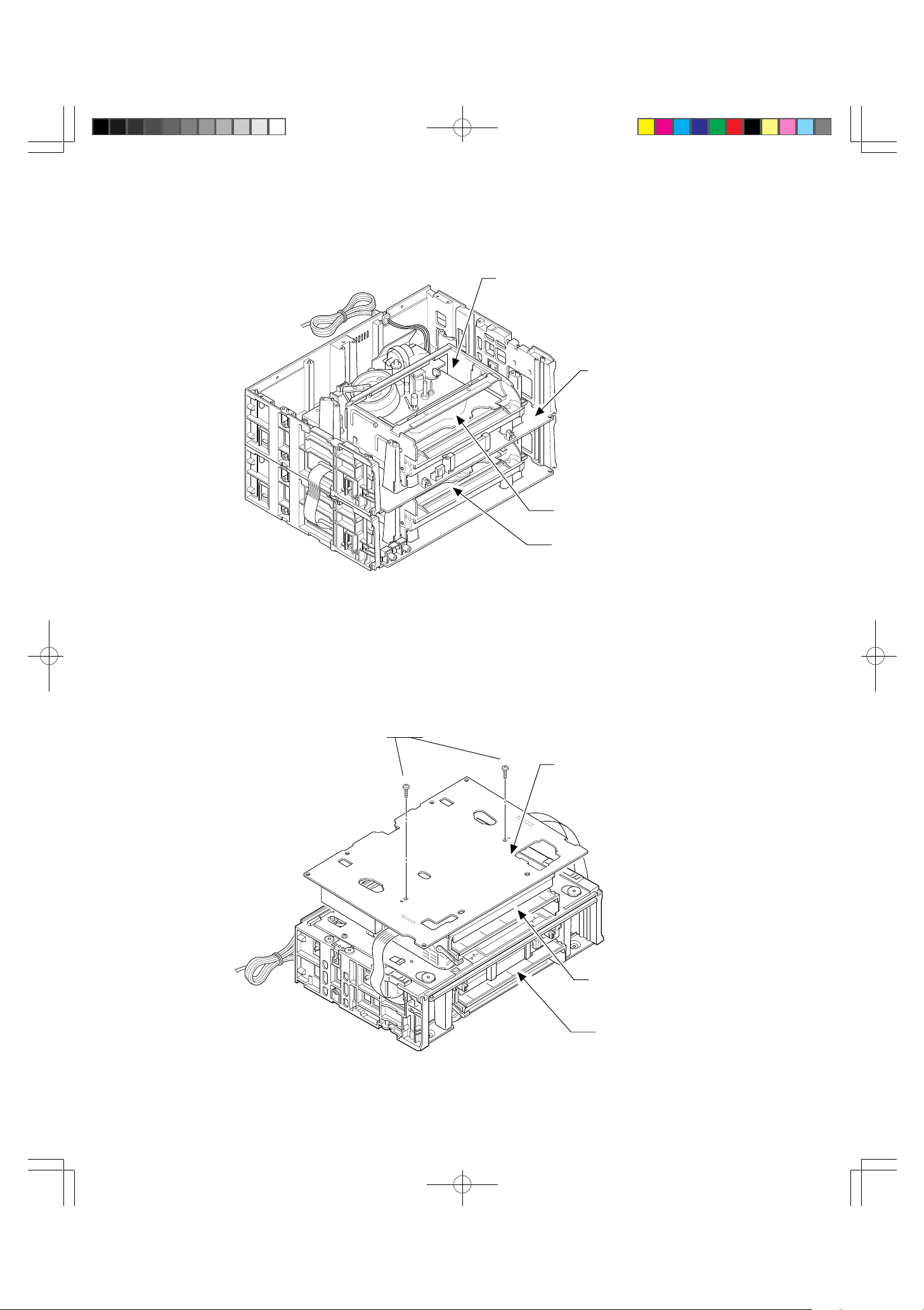
2 Mechanical Adjustment OK
Pattern (A) Original Position
R1713 1 Switching
Point Adjustment OK
Deck Unit 1
Deck Unit 2
*Fix the two spacers of the Deck Mechanism
to the back of the Main PCB with screws.
Pattern (C) External Position (Upside Down)
9 Treatment of the solder side
on the Main PCB
Deck Unit 2
Deck Unit 1
3
MV-8080G_3(2~4) 97.12.10, 20:41Page 3 Adobe PageMaker 6.0J/PPC
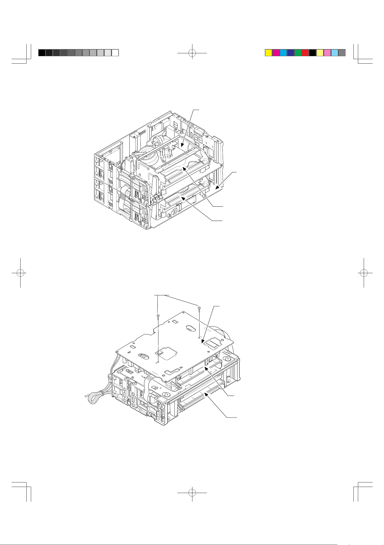
2 Mechanical Adjustment OK
R1713 1Switching
Deck Unit 2
Deck Unit 1
Pattern (B) Deck Unit 1 and 2 Positions Inverted
Point Adjustment OK
*Fix the two spacers of the Deck Mechanism
to the back of the Main PCB with screws.
9 Treatment of the solder side
on the Main PCB
Deck Unit 1
Deck Unit 2
Pattern (D) External Position (Upside Down)
4
MV-8080G_3(2~4) 97.12.10, 20:41Page 4 Adobe PageMaker 6.0J/PPC
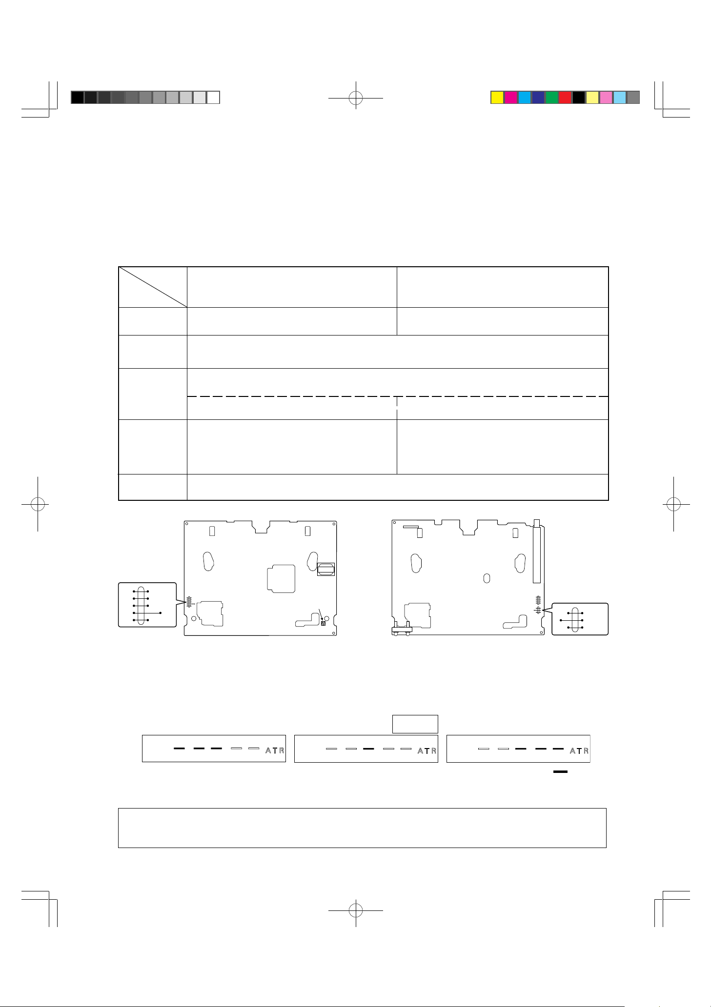
ELECTRICAL ADJUSTMENT
1. PLAYBACK SWITCHING POINT ADJUSTMENT
Mode : PLAY
Test Signal : TPS-13 or 13S
Check Point : FIP
DECK TYPE
Procedure
Adjustment
Point
1)
2)
3)
4)
FOR UPPER DECK UNIT 1 WITH POWER
SECTION
R1713 CH UP/DOWN (
FOR LOWER DECK UNIT 2 WITH TUNER
55
∞∞
5/
∞) KEY
55
∞∞
Plays the adjustment tape and automatically adjusts ATR. The ATR is finished when “ATR” on
the FIP stops blinking.
Short the connection between PG ADJ and GND on the MAIN PCB as indicated in Figure 1.
Then, must of the segments on the FIP, for example, “ATR” goes OFF. See Figure 2 below.
PG ADJ (J257), GND (J259) PG ADJ (J228), GND (J230)
To adjust the display for FIP (H1071) (Display
B below.)
• Turn R1713 to the right (in case of Display A)
• Turn R1713 to the left (in case of Display C)
To adjust the display for FIP (H701), (Display
B below).
• Press the Down ∞ key (in case of Display A)
• Press the Up 5 key (in case of Display C)
Clear the TEST POINT short.
J282
AMP
J258
CTL
J260
RFS
J259
GND
J257
PG ADJ
Figure 1-1
MAIN PCB WITH POWER SECTION FOR
UPPER DECK
Display A Display B Display C
R1713
PG ADJ
Figure 1-2
MAIN PCB WITH TUNER FOR LOWER
DECK
Adjustment
completed.
Figure 2
Due to major changes in the electrical circuits, it is sufficient to perform only this section, “PLAYBACK
SWITCHING POINT ADJUSTMENT,” of the electrical adjustments.
5
J229
J230
J228
: ON
ADJ
GND
PG ADJ
MV-8080G_4(5 97.12.11, 9:45Page 5 Adobe PageMaker 6.0J/PPC
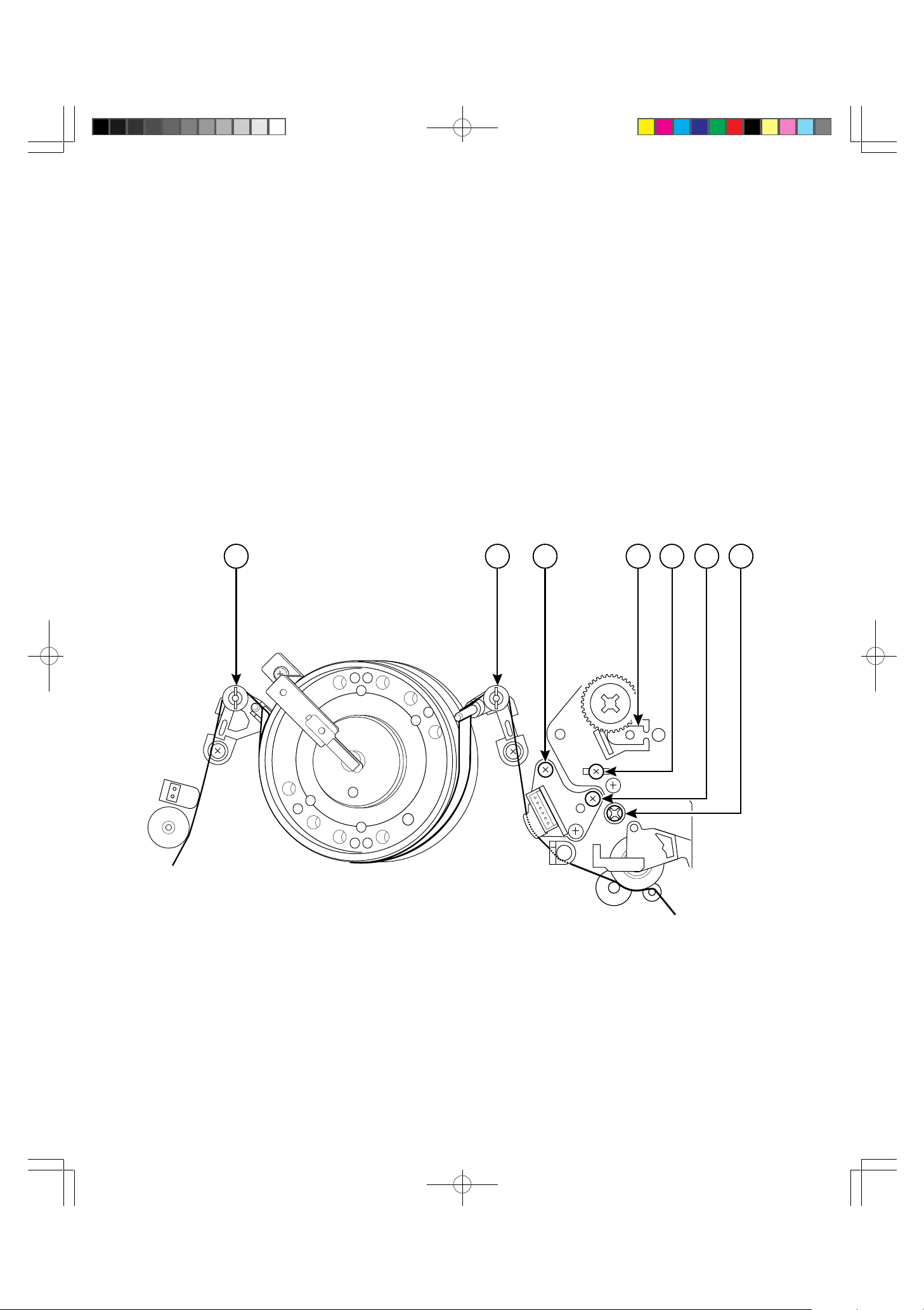
MECHANICAL ADJUSTMENT
DECK ADJUSTMENT POINTS
1 FM Waveform (Envelope) entrance adjustment screw
2 FM Waveform (Envelope) exit adjustment screw
3 Audio Azimuth adjustment screw
4 Control Head phase (X-value) adjustment point
5 Audio/CTL Head height adjustment screw
6 A/C Head tilt adjustment screw
7 RG Post height adjustment screw
1 254367
6
MV-8080G_5(6~16) 97.12.11, 9:36Page 6 Adobe PageMaker 6.0J/PPC
1. MECHANISM CONTROL
The mechanism includes its own mode as well as the operation mode of the VCR as shown in the chart below. This mode serves
an important function in working to protect the tape by passing through the VCR when the mode is switched over.
The movement of the mechanism mode is performed by the control signal of the loading motor’s rotary control circuit. With this
control, the operation mode position is detected by the Mode switch (4-bit mode data output), Cassetle ln switch, tape top sensor
and the tape end semsor which detects all modes of the mechanism.
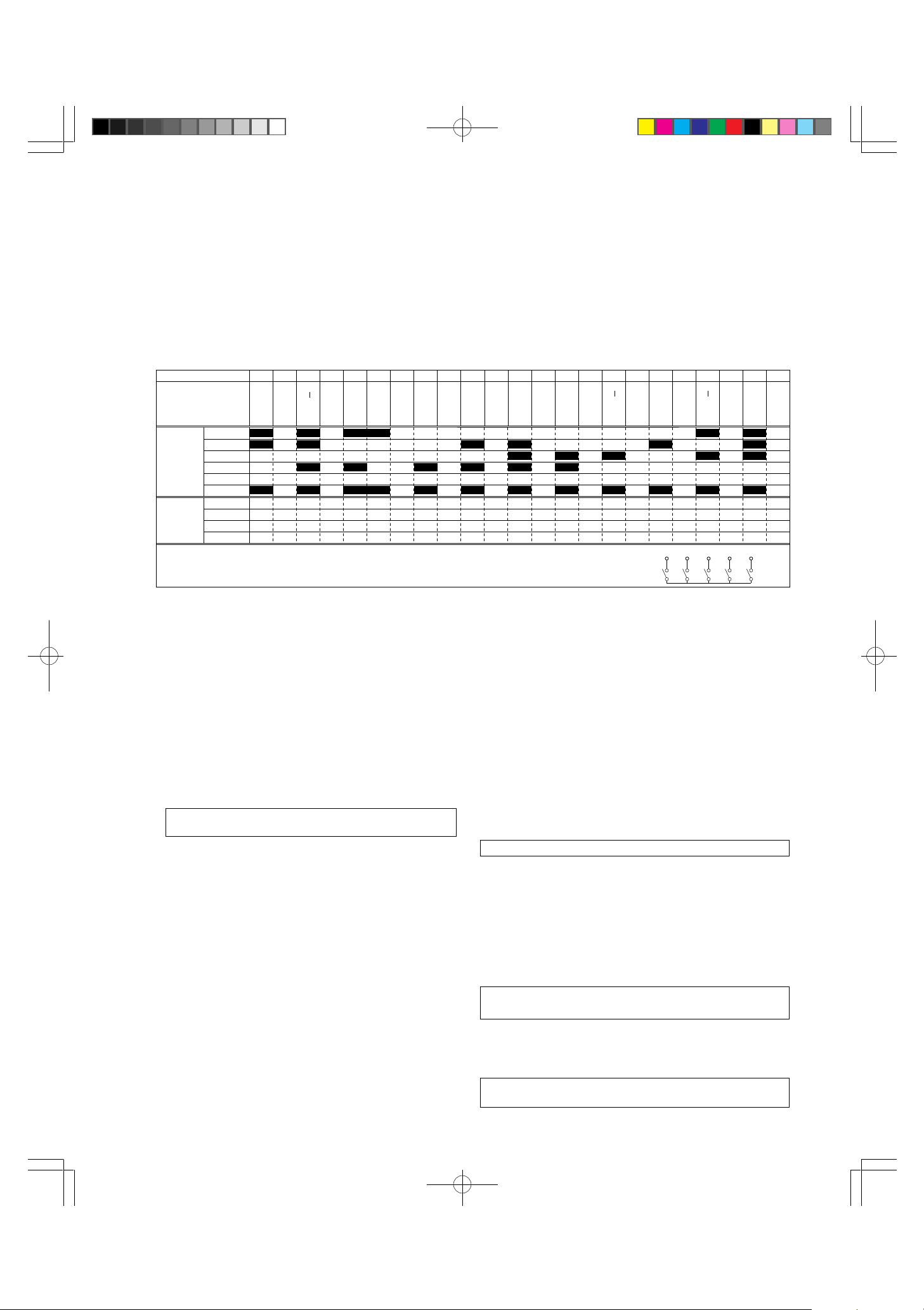
1-1. MODE SW
The composition of the 4 terminals, COM DATA 1, 2, 3, 4, are treated as a 4 bit signal.
POSITION NO
POSITION NAME
SWITCH
ON/OFF
TIMING
WHITE=OFF
BLACK=ON
POSITION
CODE
1=OFF
0=ON
M1 SW
M2 SW
M3 SW
M4 SW
COM SW
COM-M1
COM-M2
COM-M3
COM-M4
1 5 6 7 8 9 10 11 12 13 14 15 16 17 18 19 20 21 22 23234
E
J
E
C
T
S
R
E
W
ESL
O
A
D
R
E
W
F
F
S
T
O
P
P
L
A
Y
F
S
L
O
W
C
T
R
S
L
O
W
R
E
V
E
R
S
E
0 1 0 1 0 0 1 1 1 1 1 1 1 1 1 1 1 1 1 0 1 0 1
0 1 0 1 1 1 1 1 1 0 1 0 1 1 1 1 1 0 1 1 1 0 1
1 1 1 1 1 1 1 1 1 1 1 0 1 0 1 0 1 1 1 0 1 0 1
1 1 0 1 0 1 1 0 1 0 1 0 1 0 1 1 1 1 1 1 1 1 1
M1
M2
M3
MODE SW
Equivalent
Circuit
COM
COM
M1
SW
M2
SW
SW
M4
M3
M4
SW
SW
1-2. CONFIGURATION OF THE
TN6500 VCR MECHANISM
1-2-1. Cassette Drive Mechanism
The cassette is loaded and ejected via the drive from the
capstan motor.
(A) Detection of cassette insertion
When an cassette is inserted, the capstan motor starts and
simultaneously causes the shutter on the main unit to break the light
beam of the Tape Top Sensor. This capstan FG pulse and the Tape
Top Sensor change cause the cassette to be pulled into the VCR.
(B) Detection of completed cassette insertion operation
This is detected by the Cassette Insertion Switch that is linked to
the actuator activated when a cassette is inserted.
Note: The Cassette Insertion Switch is not included
with the deck mechanism.
(C) Detection of completed cassette ejection operation
As above, this is detected by the shutter on the shutter
detecting the change in the Tape Top Sensor. The light
beam that is broken by cassette insertion/ejection is restored
when the cassette has been ejected.
1-2-2. Tape Loading Mechanism
Tape loading mechanism is the mechanism that is loaded
with the tape loading motor linked to the mode switch. The
following actions occur when the 4-bit position code output
from the mode detection switch is used.
(A) The tape is pulled out of the cassette and wound on the
cylinder. (tape loading)
(B) The tape is returned to the cassette. (tape unloading)
(C) Function are switched so that each mechanism can operate.
1-2-3. Tape Transportation Mechanism
The tape is fed through the VCR by the action of the capstan,
pinch roller and reel drive.
1-2-4. Motor
(A) Capstan Motor
The drives the capstan axle directly and also drives the reel
that has been loaded on the belt. This motor is also used to
drive the cassette loading mechanism.
(B) Tape Loading Motor
In addition to cassette loading/unloading, this motor also
switched between the various operating modes(PLAY, FF/
REW etc. )
(C) Cylinder Motor
Connected to the rotating head drum and drives the rotating
head.
1-2-5. Safety Tab Sensor/Actuator
This actuator detects the tab that operates the REC SAFETY
switch.
Note: This mechanism does not include the switch.
1-2-6. Mode Sensor Switch
This detects the 4-bit code before each position and is connected
to the tape loading mechanism.
1-2-7. Take-up/Supply Reel Sensor
Photoelectric Cell
A luminous diode and phototransister at the fixed position for the cell
comprise the reel sensor. (Pulse rate=8pulses/rotation)
Note: This mechanism does not include the luminous diode
or the phototransister.
1-2-8. Tape Start/End Sensor Photoelectric Cell
A luminous diode and phototransister at the fixed position for the cell
comprise the start/end sensor. (Pulse rate=8pulses/rotation)
Note: This mechanism does not include the luminous diode
or the phototransister.
7
MV-8080G_5(6~16) 97.12.11, 9:36Page 7 Adobe PageMaker 6.0J/PPC
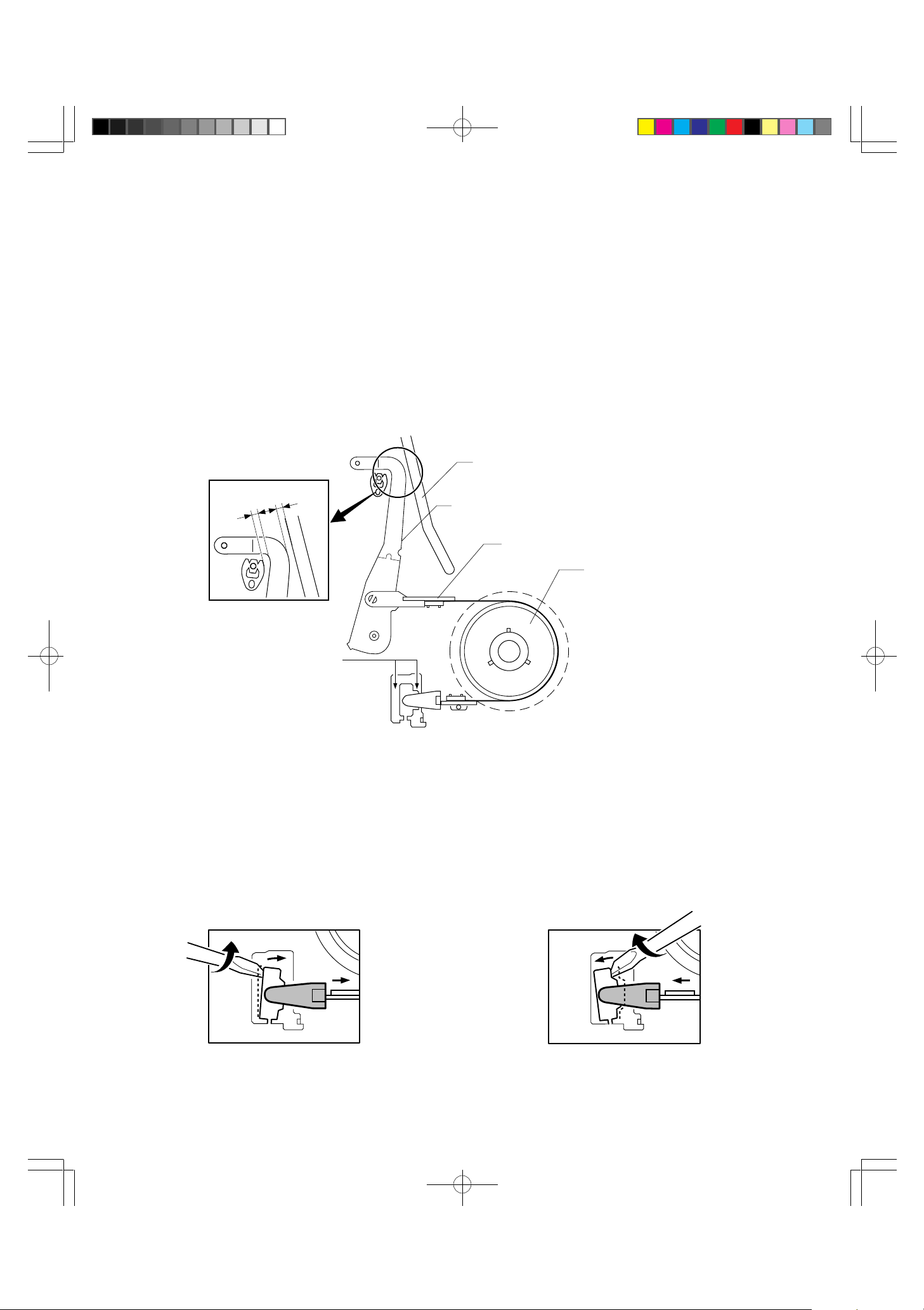
2. ADJUSTMENT OF BT TORQUE IN PLAY MODE
u
(ADJUSTMENT OF THE TENSION ARM POSITON)
1. Remove the FL Ass’y.
2. Rotate the loading pulley with your finger until PLAY mode is reached.
3. Insert a standard screwdriver into the BT adjustment groove (a or b) of the main chassis.
Twist the screwdriver left and right to adjust gap (A) and gap (B) so that they are the same.
[fBOubN
Loading Block Rail Groove
[a
A=B
B
A
Tension Arm
eVA[
BT Band Ass'y
BTohAZu
Reel Ass'y
[AZ
BT adj. Groove
BT†fipa
a b
• To reduce the gap (BT torque reduction), insert into
adjustment groove “a” and twist counter-clockwise as
shown in the figure below.
• To increase the gap (BT torque increase), insert into
adjustment groove “b” and twist clockwise as shown
in the figure below.
CAUTION: Do not twist at too much of an angle. Doing so will have adverse effects on other areas as well.
8
MV-8080G_5(6~16) 97.12.11, 9:36Page 8 Adobe PageMaker 6.0J/PPC
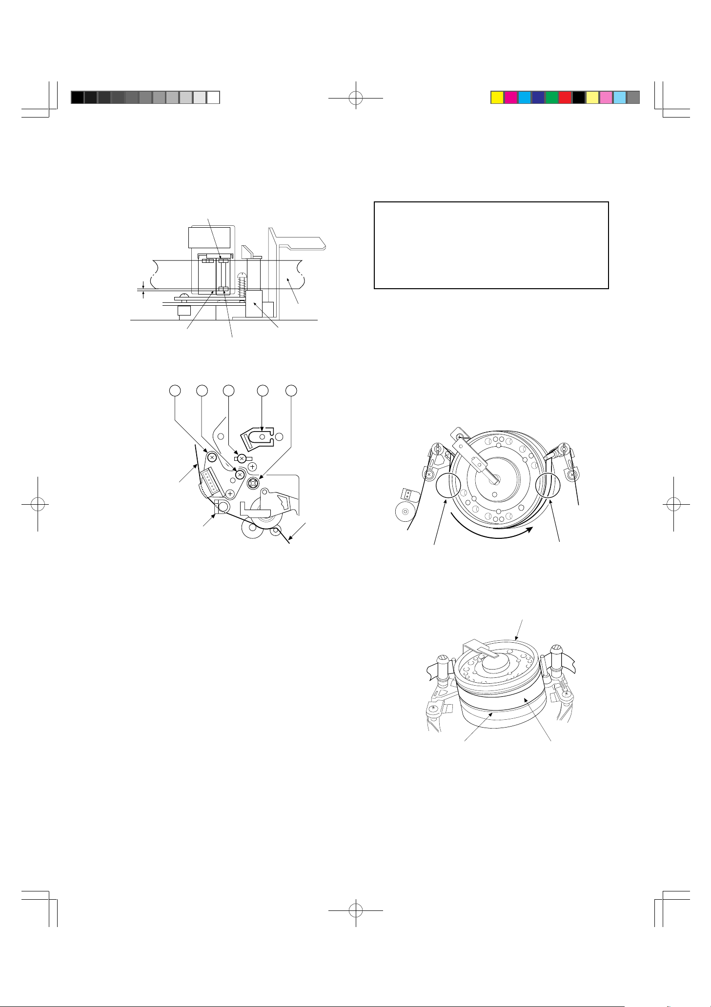
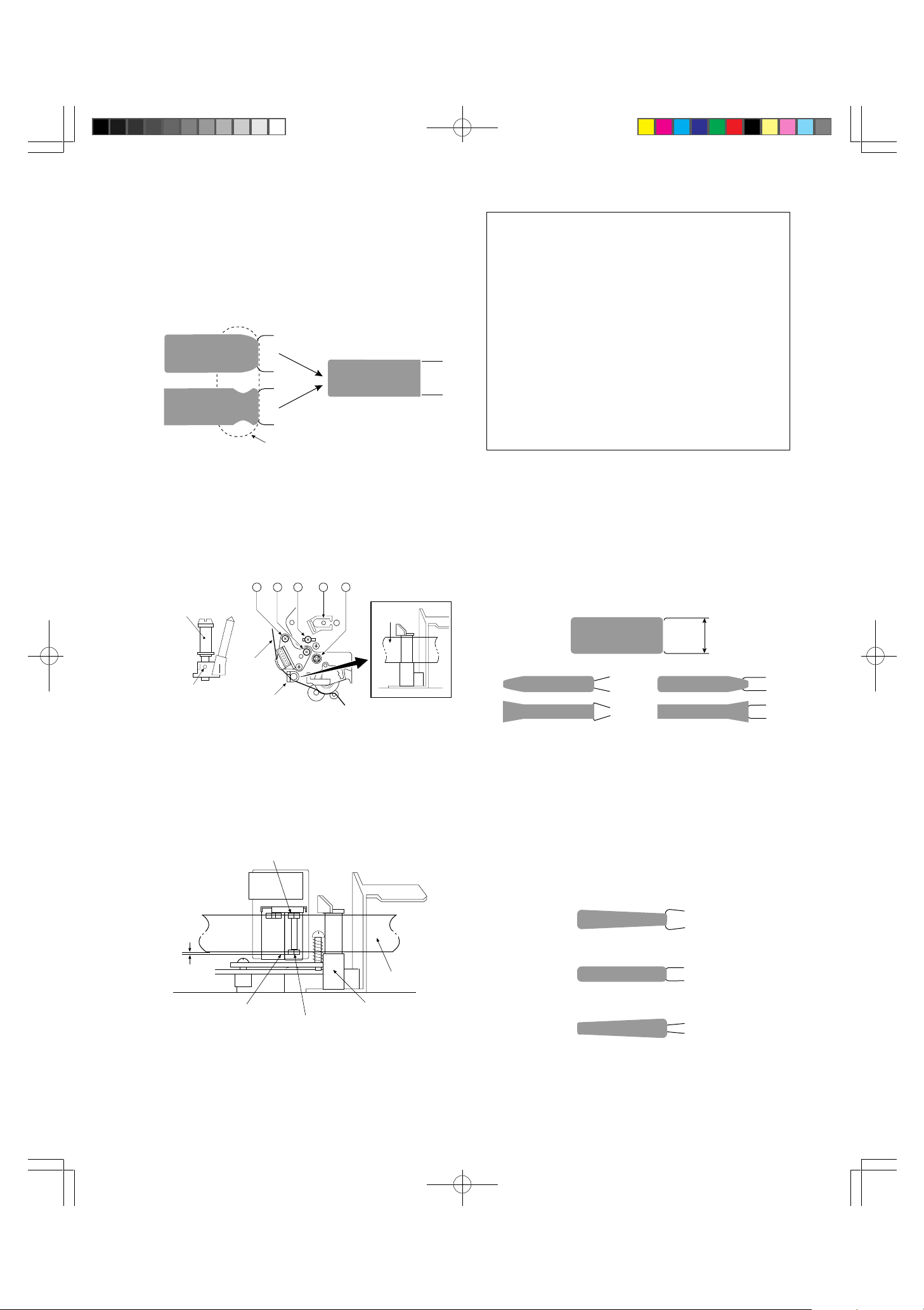
3. AUDIO/CTL HEAD
v
4. T APE TRANSPORT SYSTEM
3-1. T APE TRANSPORT ADJUSTMENT
Audio Head
Approx.
0.06mm
Reference line
CTL Head
Audio/CTL Head Adjustment
A DB EC
Tape
Take-up Guide Pole
CHECKS AND ADJUSTMENT
The tape transport system has been precisely
aligned at the factory and normally does not
require readjustment. The following steps are
therefore necessary only in cases of frequent use
or when replacing parts which have an effect on
the tape transport system.
4-1. T APE TRANSPORT CHECK
1. Using an ordinary cassette tape, switch back and
forth between PLAY and STOP modes several times.
2. During PLAY mode, observe the input and output
portions of the tape (A and B in the figure below) of
the head drum lead. Confirm that the tape slips
neither upward nor downward with respect to the
lead as shown in Figure “Drum Lead Check-1”.
Tape
e[v
e[
Tape
Take-up Guide
“«ŁKCh
1. Using an ordinary cassette tape, set to CUE mode.
2. Turn screw C and adjust for smooth transport at the
take-up guide.
3-2. AUDIO/CTL HEAD HEIGHT AND
AZIMUTH ADJUSTMENT
1. Connect the noise meter to the audio output.
2. Play the test tape (1 KHz color bar signal), turn screw
A back and forth a little at a time to set maximum
audio output level. (Rotate in a clockwise direction to
adjust the settings.)
3. Play the test tape, (8 KHz stair step signal), turn
screw B back and forth a little at a time to adjust the
azimuth so that the audio output level will reach a
maximum.
4. Play the test tape (1 KHz color bar signal), and make
sure that there is no significant change in the audio
output level. If a large change remains, turn screw C
back and forth a little at a time to adjust so that the
level change will reach a minimum.
5. When all adjustment is finished, lock up screw B.
A:hß B:ho
Tape Transport Check
Upper Drum Ass'y
ªhAZu
Drum Lead (lower)
h[hiӧj e[v
Drum Lead Check-1
Drum OutputDrum Input
Tape
9
MV-8080G_5(6~16) 97.12.11, 9:36Page 9 Adobe PageMaker 6.0J/PPC
NOTES:
1. If the tape slips upward; sound is produced by
contact between the tip of rotating heads and
the edge of the tape.
2. If the tape slips downward; the tape curls or
wrinkles (or makes noise) at its connection
with the lead face of the drum lead.
3. During loading, play, and unloading of the
cassette tape, observe the tape at the supply
guide roller, and take-up guide roller.
4. Make sure that there are no curls or wrinkles as
shown in the figure below.
Incorrect
Tape
Correct
4-2. GUIDE ROLLER HEIGHT
ADJUSTMENT
1. Slightly loosen the tight-screw of the supply and takeup guide rollers as shown in the figure below.
2. Using an ordinary cassette tape, set to PLAY mode.
3. With a standard screwdriver, slightly turn the supply
guide roller (no more than 180° at a time), and adjust
so that at the drum input portion, the tape travels
smoothly along the drum lead without slipping
upwards or downwards.
4. Similarly, adjust the take-up roller for the drum output.
hCo[¯æ
Turn with a
standard screwdriver
Guide
roller
AB C
Guide Roller
5. Observe the tape as it wraps around the drum
during PLAY and separates from the drum
during STOP.
6. As shown in the figure below, make sure that
there is no damage to C and D and that there
is no contact noise between the head tips and
tape edge.
Upper Drum Ass'y
e[v
Ło
Supply Guide Roller
KCh[
Tape
ªhAZu
“«Ł
Take-up
KCh[
Guide Roller
Guide Roller
KCh[
¯ŁlW
Tight Screw
Adjusting Guide Roller Height
NOTES:
1. Loosen the tight-screw only enough to allow
the guide rollers to be rotated. Loosening it
anymore than that may rotate the roller
inadvertently as a result of tape motion.
2. Rotate the roller carefully to avoid damage to
the tape.
3. When the adjustment is completed, tighten the
screw and set by locking up the screw.
D
Drum Lead
h[h
C
Drum Lead Check-2
7. If a defect is detected during check, perform
the follwoing procedure for adjusting Guide
Roller height.
10
MV-8080G_5(6~16) 97.12.11, 9:36Page 10 Adobe PageMaker 6.0J/PPC

4-3. TAPE TRANSPORT CHECK AT
v
THE T AKE-UP GUIDE
In general, no adjustment will be necessary for the takeup guide. However, adjustments or checks will be
necessary when replacing the Audio/CTL Head or parts
affecting the tape transport system after a long period of
operation.
1. Using an ordinary cassette tape, set to PLAY mode.
2. Turn Audio/CTL Head screw C as shown in the
figure below and adjust for smooth transport at the
Take-up Guide.
A DB EC
X|WVAWXg¡
X position Adjusting Jig
Tape
e[v
e[
Tape
Take-up Guide
“«ŁKCh
5. INTERCHANGEABILITY
ADJUSTMENT
Before using the test tape, make sure that the tape
transport is normal using an ordinary cassette tape.
Also, make sure that the switching point (Refer to P.5)
is adjusted. If they are not, do the following checks after
adjusting.
5-1. PRELIMINARY CHECKS
1. FM Envelope Waveform Check
1. Connect the CH-1 oscilloscope to TP of PB ENV and
CH-2 to TP of CTL. At this time, trigger the
oscilloscope externally with the signal (RF Switching
Pulse) from TP of RFS.
2. Play the test tape (Stairstep).
3. Use the Channel ∞/5 buttons to tune the tracking to
center position. Adjust point 4 (X value adjustment
point: test point reference P.6) so that the FM
envelope output at TP of PB ENV reaches a maximum.
4. Using the Channel ∞/5 buttons. Perform the following
3 steps (5-7) by moving the TP of CTL waveform in
both positive (+) and negative (–) directions in 3 ms
increments.
5. Refer to the figure below. Read the level of portion
(a) of the waveform. If the waveform is serrated at
point (a), adjust the level so that the serrations are as
smooth as possible (refer to the second figure).
ce
a
abd
Ideal FM envelope
FM Waveform (Maximum Output)
Minimum levelMaximum level
Normal Waveform Examples
11
MV-8080G_5(6~16) 97.12.11, 9:36Page 11 Adobe PageMaker 6.0J/PPC
6. As shown in the equation below, read the FM
waveform value at point (b) and make sure that:
b
> 0.75 or 20 log > –2.5 dB
=
a
b
=
a
7. Read the values at points (c) and (d) [drum input and
output] and make sure that:
c
> 0.75 and > 0.75 or
=
a
20 log = –2.5 dB and
20 log = –2.5 dB
c
a
e
a
d
=
a
NOTES:
1. Read the minimum levels for (b), (c), and (d).
2. If above checks yield normal results, proceed
to page MA-8 section “ADJUSTMENT”.
3. If defects are noted, perform the following FM
envelope waveform adjustment.
2. FM ENVELOPE WAVEFORM
ADJUSTMENT
1. As in the previous section, observe the FM waveform
and press the CHANNEL ∞/5 buttons. Waveform
alterations must be nearly parallel to each other as
shown in Figure “Normal Waveform Examples” on
page P.11.
2. If the waveform changes as shown in the figure
below, adjustment is necessary.
5-2. ADJUSTMENT
1. Connect the TP of PB ENV to the oscilloscope
CH-1. At this time, trigger the oscilloscope externally
with the signal (RF Switching Pulse) from TP of RFS.
2. Play the test tape (Stairstep).
1. DRUM INPUT ADJUSTMENT
1. Observe the FM envelope output wave at the TP of
PB ENV with the oscilloscope and press the
CHANNEL ∞/5 buttons in both positive (+) and
negative (–) directions.
2. A of the following figure shows incorrect waveforms.
With a standard screwdriver, adjust the transport
guide roller to flatten the peak of the FM envelope
waveform as shown in B.
NOTES:
1. If the guide roller rotates freely, tighten the
screw slightly.
2. Be sure to adjust the guide roller only by small
increments at a time to avoid damaging the
test tape.
In addition to observing the waveform, make
sure that there is no slipping of the tape or
curling at the drum lead.
AB
Drum input
Abnormal Waveform Example
Supply Guide Roller
Tight Screw
Tape
Supply Guide Roller
Drum Input Adjustment
12
MV-8080G_5(6~16) 97.12.11, 9:36Page 12 Adobe PageMaker 6.0J/PPC
2. DRUM OUTPUT ADJUSTMENT
1. Adjust the take-up guide roller so that the FM
envelope output flattens as shown in D of the figure
below.
CD
Drum output
Drum Output Adjustment
NOTES:
1. Fine adjustments are not required at this time.
It is sufficient if the tape is engaged with the
guide and that the servo operates properly
(control signal picked up).
2. If the tape separates from the take-up guide or
wrinkling occurs, screw C must have been
excessively tightened with respect to screw A
and screw B, which is causing the Audio/CTL
Head to incline forward or backward. Use care
in adjusting screws B and C, and screw A
evenly and observe that wrinkles are not
produced at the take-up guide.
2. If the tape separates from the guide or wrinkling
occurs at the take-up guide, adjust by turning screw
C of the Audio/CTL Head as shown in the figure
below.
AB E
Take-up
“«Ł
Guide Roller
KCh[
¯ŁlW
Tight Screw
e[v
Tape
“«Łe[vKCh
Take-up Guide
DC
Tape
e[v
Take-up Guide
3. As shown in the figure below, adjust screws B and
C and screw A to align the Audio/CTL Head
height with the tape.
Audio Head
5-3. INTERCHANGEABILITY
ADJUSTMENT
1. Observe the FM envelope output waveform at the
oscilloscope and press to adjust the CHANNEL ∞/5
buttons in both positive(+) and negative(-) directions.
Maximum
AC
DB
Minimum FM Output (Incorrect Examples)
2. If there are waveforms as shown in A or B in the
above figure, adjust the supply guide roller height so
that the waveform appears as shown by E, F, or G
in the figure below. At this time, if the waveform
fluctuates, adjust to the point of minimum fluctuation.
Taper
Parallel
Taper
Approx.
0.06mm
Reference line
CTL Head
Tape
Take-up Guide Pole
E
F
G
Audio/CTL Head Height
Minimum FM Output (Correct Examples)
13
MV-8080G_5(6~16) 97.12.11, 9:36Page 13 Adobe PageMaker 6.0J/PPC
3. If the FM waveform appears as shown by C or D in
the above figure, adjust the take-up guide roller
height to obtain a waveform such as shown in E, F,
or G.
At this time, if the waveform fluctuates, adjust to the
point of minimum fluctuation.
4. Vary the tracking control from maximum to minimum
FM output.
Perform fine adjustment of supply and take-up guide
rollers so that waveform variation appears as shown
in E, F, or G.
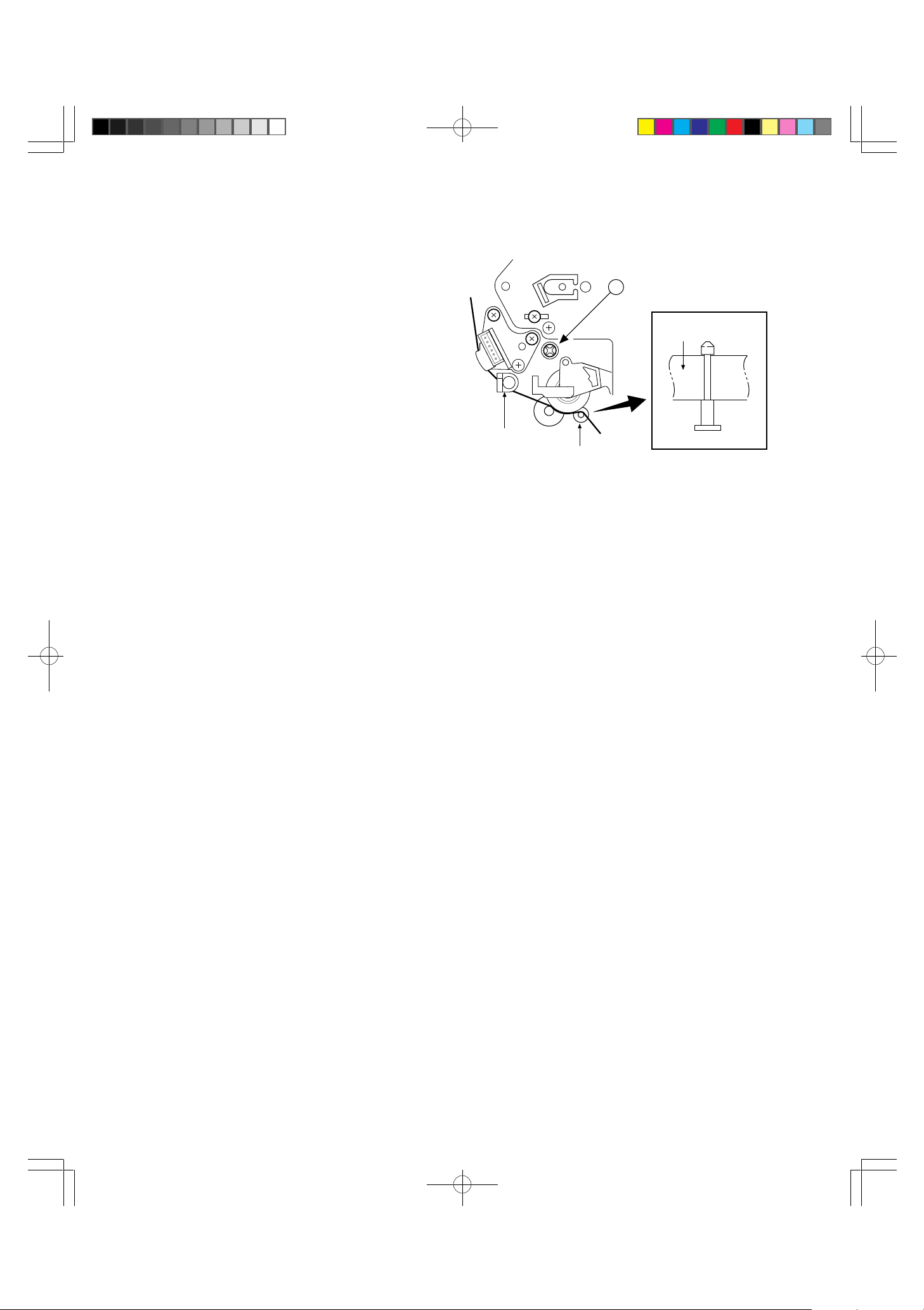
6. RG POST HEIGHT ADJUSTMENT
E
Tape
5-4. AUDIO/CTL HEAD HEIGHT,
AZIMUTH AND SLANT
Refer to 3-2 (P.9) for details regarding AUDIO/CTL
HEAD HEIGHT AND AZIMUTH ADJUSTMENT.
5-5. SETSCREW TIGHTENING
1. Check for maximum FM output waveform, maximum
audio output, and be sure that there is no wrinkling on
the tape or other transport irregularities. When
finished, secure the guide rollers. (This must be
performed in STOP mode.)
2. Because the guide rollers are easily moved, use care
when securing.
3. After tightening the screws, perform the final interchangeability check.
5-6. FINAL INTERCHANGEABILITY
CHECK
Perform preliminary checks referring to section “PRELIMINARY CHECKS” on page P.11.
Take-Up Guide
RG Post
1) Use a blank tape and set the VCR to REV mode.
2) Adjust the RG Post height adjusting screw E so that
the tape runs along the lower flange of the Take-Up
Guide.
14
MV-8080G_5(6~16) 97.12.11, 9:36Page 14 Adobe PageMaker 6.0J/PPC
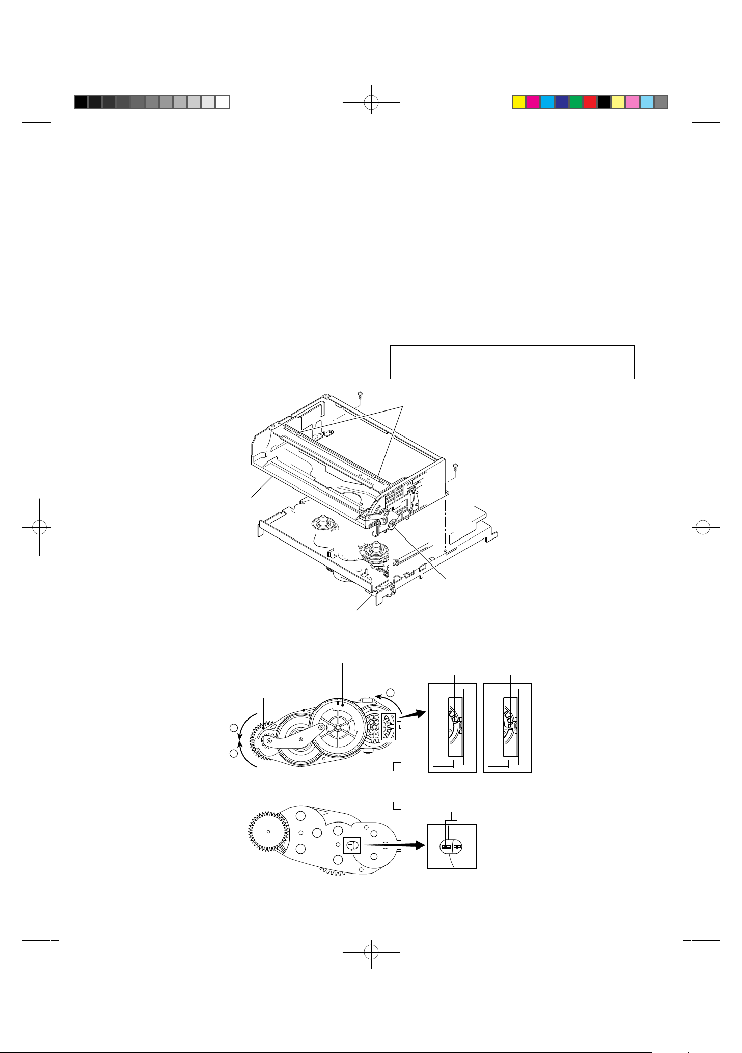
7. FRONT LOADING ASSEMBLY ATTACHMENT
To attach the Front Loading Assembly, follow the procedures below.
1) Twist the loading motor with your finger until it is in
EJECT mode.
2) Twist the FD Pinion Gear counterclockwise until it
stops. (The FD Face Gear is loose. )
3) Twist the FD face Gear counterclockwise until it
stops, then apply gentle pressure in the
counterclockwise direction.
4) In the position at step 2) , rotate the FD Pinion Gear
clockwise. After about 3 1/2 turns, the FD Pinion Gear
should begin to interlock with the FD Relay Gear.
Now twist the FD Pinion Gear until it stops. (The
assembly should now resemble Fig. 2)
5) Twist the FD Pinion Gear about 1/3 of a turn
counterclockwise so that the Lift Gear R attachment
position is horizontal making attachment easier, as
shown in Fig. 3. Also, the FD Relay Gear and FD
Face Gear eye marks should be aligned when the
MD is viewed from the back. (Fig. 4)
6) Attach the front assembly.
Insert the first Lift Gear R between the first and
second gear of the front assembly. (Fig. 3)
Note: Do not touch the CSP plate of the Front Loading
Assembly. (Take care not to distort it.)
CSP plate
Front Loading A'ssy
FD Gear Case
FD Pinion Gear
2
4
Fig. 1 View from above the MD
FD Gear Case
FD Relay Gear
FD Face Gear
Lift Gear R
Align first gear on Lift Gear R.
3
Fig. 2
Fig. 3
Eye mark
Fig.4 MD Rear View
15
MV-8080G_5(6~16) 97.12.11, 9:36Page 15 Adobe PageMaker 6.0J/PPC

PERIODIC MAINTENANCE
The following procedures are recommended for maintaining optimum performance and reliability of this video
cassette recorder.
CLEANING
For cleaning, use a lint-free cloth or gauze dampened
with alcohol.
TAPE TRANSPORT SYSTEM
1. The following components should be cleaned after
every 500 hours of use.
• Impedance Roller
• Tension Post
• Transport Slide Post
• Supply Guide Roller
• Take-up Slide Post
• Take-up Guide Roller
• Video Head & Drum System
• Drum Ground
• Drum Motor Shaft
• Audio/CTL Head
• Pinch Roller
• Capstan
• Reverse Guide Post
• Full Erase Head
• Tape Guide
• F Post
REEL DRIVE SYSTEM
1. The following components should be cleaned after
every 1000 hours of use.
TOP BOTTOM
• Take-up Reel Table Ass’y • Capstan Motor Pulley
• Supply Reel Table Ass’y • Clutch Pulley
• T Soft Brake Ass'y • Drive Belt
• T Main Brake Ass'y • C Brake
• S Main Brake Ass'y
• BT Band Ass'y
2. The above revolving parts are of rubber or come in
direct contact with rubber parts. Dust on rubber
accumulates and interferes with proper operation.
3. Avoid using excessive alcohol when cleaning rubber
parts.
2. Since the above parts come in direct contact with
video tape, they tend to collect dust particles. If
allowed to accumulate, dust may lead to damage to
the video tape and above parts.
3. After cleaning with alcohol, allow the parts to dry
thoroughly before using a cassette tape.
NOTE:
• When cleaning the two video heads on the
upper drum, do not clean them with a vertical
stroke.
• Use only a gentle back and forth motion in the
direction of the tape path.
16
MV-8080G_5(6~16) 97.12.11, 9:36Page 16 Adobe PageMaker 6.0J/PPC
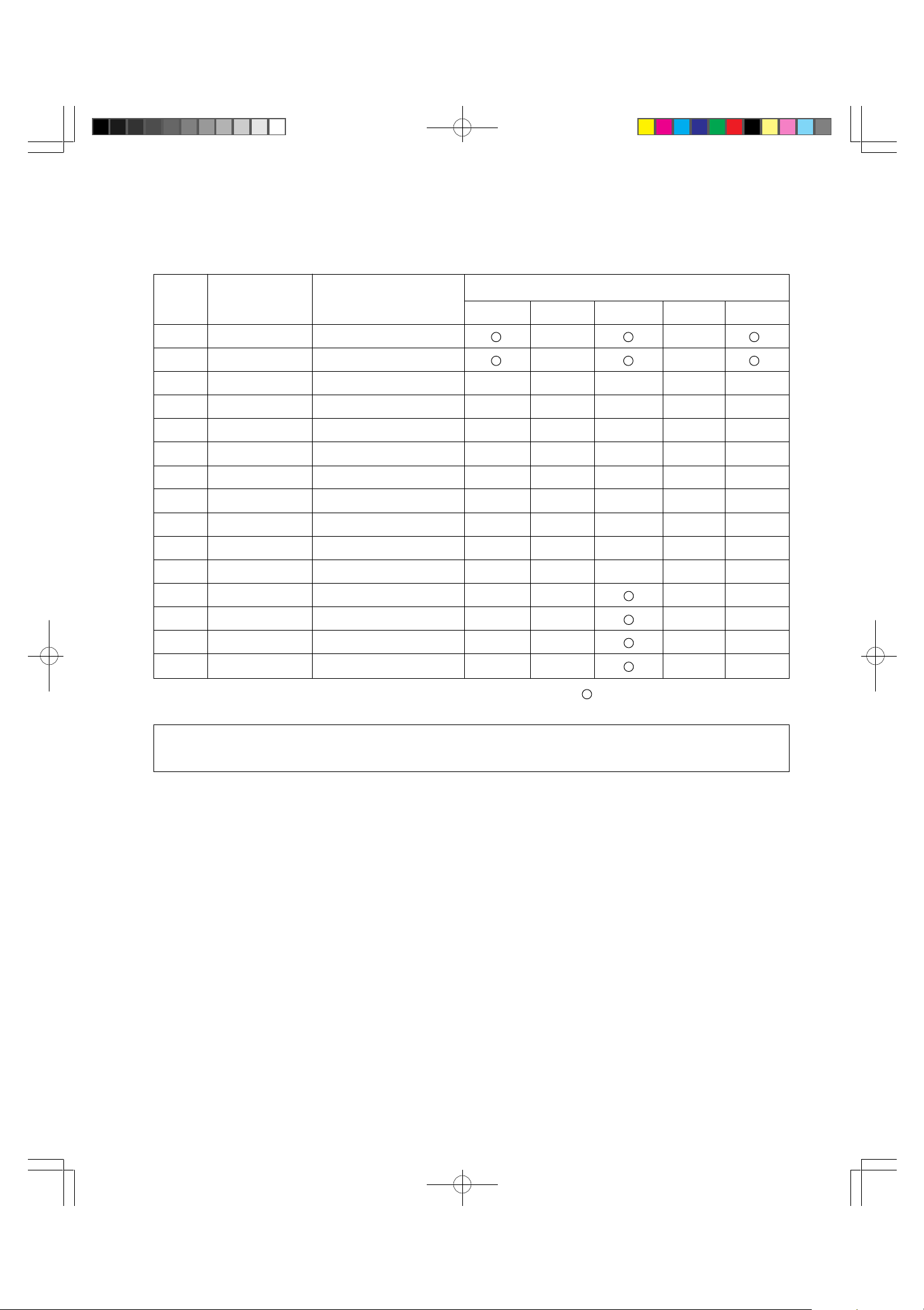
SERVICE SCHEDULE FOR MAIN COMPONENTS
The following table lists the parts which should receive periodic servicing at the recommended intervals.
Ref. No Part No.
Description
1000 2000 3000 4000 5000
1 62D806501603 Cylinder Ass’y for 59277 ●●
1 62D806501603 Cylinder Ass’y for 59311 ●●
90 62D806506301 Pinch Roller Arm Ass'y ●●
116 62D806508303 BT Band Ass’y ●●
128 62D806509302 Clutch Ass’y ●●
131 62D80650920 Drive Belt ●●
132 62D806510301 T Main Brake Ass’y ●●
133 62D806510302 S Main Brake Ass’y ●●
134 62D806510303 T Soft Brake Ass'y ●●
61 62D62041520 A/C & E Head for 59277 ●
61 62D62040324 Audio/CTL Head for 59311 ●
80 62D806505301 T Reel Ass’y
81 62D806505302 S Reel Ass’y
100 62D60030360 Capstan Motor Ass’y
Periodic Service Schedule (operating hours)
142 62D806511303 Loading Motor Ass'y
Standard Service Periods Check and replace if necessary
● Replace
NOTE:
Cleaning and replacement of the belts should be undertaken every 2 years even if the unit is not used frequently.
17
MV-8080G_6(17~18) 97.12.11, 9:49Page 17 Adobe PageMaker 6.0J/PPC


CASSETTE DECK MECHANISM 59277, 59311
Ref. No. TN Part No. ST Part No. Description
1 8065-01-603 62D806501603 CYLINDER ASS’Y
2 8065-01-305 62D806501305 V OUT PWB ASS’Y
3 6809-70-243 62D680970243 FPC4 CONNECTOR (C)
4 9P12-26-064 62D9P1226064 TAMS SCREW,2.6X6MM
5 8065-01-501 62D806501501 DRUM EARTH ASS’Y
6 9P04-26-041 62D9P0426041 TAPPING SCREW,2.6X4MM
7 8065-01-2316 62D806501316 DRUM MOTOR ASS’Y
8 9P02-26-151 62D9P0226151 TAMS SCREW 2.6X15
9 8065-01-315 62D806501315 ROTOR SCREW ASS’Y
10 9P04-30-051 62D9P0430051 TAPPING SCREW 3.0X5
20 8065-02-301 62D806502301 F POST METAL ASS’Y
21 8065-02-303 62D806502303 TAPE GUIDE BASE ASS’Y
22 8063-02-23 62D80630223 CASSETTE GUIDE BOSS
23 8065-02-21 62D80650221 TAPE PROTECT
24 8065-02-304 62D806502304 TAPE GUIDE ASS’Y
30 8065-03-502 62D806503502 LOADING LEVER KASIME
31 8063-03-305 62D806303305 LOADING PLATE L ASS’Y
32 8065-03-305 62D806503305 LOADING PLATE R ASS’Y
33 9W06-50-110 62D9W0650110 HL WASHER,4.5X7X0.5(CUT)
34 8065-03-303 62D806503303 L BLOCK L ASS’Y
35 8065-03-304 62D806503304 L BLOCK R ASS’Y
36 8063-03-09 62D80630309 ROLLER POST
37 8065-03-04 62D80650304 LOADING GEAR
38 8065-03-05 62D80650305 L GEAR PLATE
39 8065-03-11 62D80650311 L GEAR PLATE COLLOR
40 9W02-50-100 62D9W0250100 P.WASHER,2.1X5X0.5(CUT)
41 9W02-50-110 62D9W0250110 P.WASHER,2.6X6X0.5(CUT)
42 8065-03-10 62D80650310 L GEAR PLATE SPRING
43 8065-03-01 62D80650301 LD CATCHER
44 9P04-26-051 62D9P0426051 SCREW,2.6X5MM
45 8065-03-306 62D806503306 HEAD CLEANING ASS’Y
46 8063-03-29 62D80630329 CLEANING ROLLER ASS’Y
47 9W02-30-050 62D9W0230050 P.WASHER,1.6X3.8X0.3(CUT)
48 9C17-20-233 62D9C1720233 CAMERA SCREW 2 X2.3MM
60 8065-04-302 62D806504302 ACE HEAD BASE ASS’Y
61 6204-15-20 62D62041520 ACE HEAD HVMZA1220
60 8065-04-303 62D806504303 AC HEAD BASE ASS’Y
61 6204-03-24 62D62040324 AC HEAD HVMZB1030
62 8000-06-04 62D80000604 AZIMUTH SPRING
63 8000-06-26 62D80000626 AZIMUTH SPRING SCREW
64 9P09-30-061 62D9P0930061 SCREW,3X6MM(FIXING)
65 9P01-26-072 62D9P0126072 SCREW,2.6X7MM
66 8065-04-301 62D806504301 FE HEAD BASE ASS’Y
67 6209-15-04 62D62091504 VTR1X2ERS11107
*
68 8063-04-306 62D806304306 IMPEDANCE ROLLER ASS’Y
69 9W02-30-050 62D9W0230050 P.WASHER,1.6X3.8X0.3(CUT)
LOWER DECK (59277) FOR REC/PB
UPPER DECK (59311) FOR P.B. ONLY
LOWER DECK (59277) FOR REC/PB
19
MV-8080G_7(19~21) 97.12.11, 9:51Page 19 Adobe PageMaker 6.0J/PPC

CASSETTE DECK MECHANISM 59277, 59311
Ref. No. TN Part No. ST Part No. Description
70 9W06-30-040 62D9W0630040 HL WASHER,1.55X4.5X0.3(CUT)
71 8065-04-02 62D80650402 HEAD BASE SPRING
80 8065-53-01 62D806505301 T REEL ASS’Y
81 8065-05-302 62D806505302 S REEL ASS’Y
82 9W03-30-110 62D9W0330110 NYLON WASHER 2.5X5X0.3
90 8065-06-301 62D806506301 PINCH ROLLER ARM ASS’Y
91 8065-06-05 62D80650605 PINCH ROLLER
92 9B01-26-041 62D9B0126041 SCREW,2.6X4MM
93 8065-06-501 62D806506501 PINCH ROLLER KASIME
94 8065-06-04 62D80650604 PINCH ROLLER SPRING
100 6003-03-60 62D60030360 CAPSTAN MOTOR (F2QTB10)
101 9P07-26-061 62D9P0726061 TAPPING SCREW P 2.6X6
102 8065-07-301 62D806507301 C BRAKE ASS’Y
103 9W02-50-100 62D9W0250100 P.WASHER,2.1X5X0.5(CUT)
104 8065-07-02 62D80650702 C BRAKE SPRING
110 8065-08-301 62D806508301 TENSION ARM ASS’Y
111 8063-08-04 62D80630804 BT ARM METAL
112 8065-08-02 62D80650802 BT SPRING
113 8065-08-06 62D80650806 BT LEVER
114 9W02-50-110 62D9W0250110 P.WASHER,2.6X6X0.5(CUT)
115 8065-08-302 62D806508302 TENSION ARM SEMI ASS’Y
116 8065-08-303 62D806508303 BT BAND ASS’Y
120 8065-09-303 62D806509303 SUB PLATE ASS’Y
121 9C04-26-503 62D9C0426503 CAMERA SCREW(TAPPING)S 2.6X5
122 9P04-20-041 62D9P0420041 TAPPING SCREW 2.0X4
123 8065-09-304 62D806509304 RF CLUTCH ASS’Y
124 9W02-50-110 62D9W0250110 P.WASHER,2.6X6X0.5(CUT)
125 8065-10-09 62D80651009 SS BRAKE SPRING
126 8065-10-07 62D80651007 TS BRAKE SPRING
127 8065-10-10 62D80651010 TS BRAKE LEVER
128 8065-09-302 62D806509302 CLUTCH ASS’Y
129 8065-09-301 62D806509301 CLUTCH PULLY ASS’Y
130 9W02-30-060 62D9W0230060 P.WASHER,2.1X5X0.3(CUT)
131 8065-09-20 62D80650920 DRIVE BELT
132 8065-10-301 62D806510301 T MAIN BRAKE ASS’Y
133 8065-10-302 62D806510302 S MAIN BRAKE ASS’Y
134 8065-10-303 62D806510303 T SOFT BRAKE ASS’Y
135 8065-11-13 62D80651113 REVERSE LEVER
136 8065-09-307 62D806509307 GEAR PLATE ASS’Y
137 8065-10-05 62D80651005 MAIN BRAKE SPRING
138 8065-10-08 62D80651008 S SOFT BRAKE ARM
139 8065-11-14 62D80651114 REVERSE LEVER PIN
140 8065-11-302 62D806511302 CAM GEAR ASS’Y
141 8065-11-301 62D806511301 CAM PLATE ASS’Y
142 8065-11-303 62D806511303 LOADING MOTOR ASS’Y
143 8065-11-11 62D80651111 MOTOR HOLDER
20
MV-8080G_7(19~21) 97.12.11, 9:51Page 20 Adobe PageMaker 6.0J/PPC

CASSETTE DECK MECHANISM 59277, 59311
Ref. No. TN Part No. ST Part No. Description
144 9P02-26-051 62D9P0226051 TAMS SCREW 2.6X5
145 9F22-26-081 62D9F2226081 ADJUST SCREW 2.6X8
146 8065-11-04 62D80651104 M GEAR
147 8065-11-305 62D806511305 M GEAR PLATE ASS’Y
148 8065-11-07 62D80651107 M RELAY GEAR
149 9W06-30-100 62D9W0630100 HLW(C) 2.6X6X0.3
150 8065-11-08 62D80651108 M SLIDE PLATE
151 8065-11-17 62D80651117 R LEVER SPRING PLATE
152 9P04-26-051 62D9P0426051 SCREW,2.6X5MM
153 8065-11-03 62D80651103 CAM DRIVE GEAR
154 8065-11-10 62D80651110 WORM WHEEL
155 8065-11-15 62D80651115 OPEN ANGLE
156 8065-11-16 62D80651116 AH ADJUST NUT
160 8065-13-01 62D80651301 OPTICAL LEADER
161 8065-13-303 62D806513303 RS LEADER
162 8065-13-04 62D80651304 REC SWITCH LEVER
*
163 8065-13-05 62D80651305 REC LEVER SPRING
*
164 8065-13-06 62D80651306 IN SWITCH SLIDER
165 8065-13-07 62D80651307 IN SW SLIDER SPRING
166 8065-13-302 62D806513302 BASE PWB ASS’Y
167 8065-13-11 62D80651311 DM LEAD PWB
168 8065-13-12 62D80651312 CM LEAD PWB
169 9P04-26-051 62D9P0426051 SCREW,2.6X5MM
180 8065-15-09 62D80651509 FD SLIDE PLATE
181 8065-15-10 62D80651510 FD SLIDE PLATE SP
182 8065-15-301 62D806515301 FD GEAR CASE ASS’Y
190 8065-16-301 62D806516301 FRONT LOADING ASS’Y
191 9B03-26051 62D9B0326051 SCREW,2.6X5MM
192 9P04-26-051 62D9P0426051 SCREW,2.6X5MM
200 8065-17-501 62D806517501 RG ARM KASIME
201 8065-17-03 62D80651703 RG ADJUST NUT
202 8065-17-04 62D80651704 RG LEVER
203 8065-17-05 62D80651705 RG ARM SPRING
LOWER DECK (59277) FOR REC/PB
21
MV-8080G_7(19~21) 97.12.11, 9:51Page 21 Adobe PageMaker 6.0J/PPC

DECK 1
DECK 2
LOADING DRIVER
IC1601
TA7291S
I/R SENS UNIT
MD1701
DECK
TN6500
DECK
SW
SERVO AMP
IC1501
LA7116
SENSOR
NORMAL AUDIO
IC1401
LA7286
BIAS OSC
Q1401
VIDEO
HEAD AMP
IC1102
LA7411
POWER
CPU
IC1701
CXP88132
KEY
SWITCH
DISPLAY
PB EQ
REC EQ
I HDL
HQ PB
Y-EQ
HQ PB
C-BPF
HQ LIMITER
IC1301
AN6326N
IC1801
PH530090
IC1802
KIA431
Q1804
IC2D03
LA7016
AUDIO
SWITCH
IC
IC2D02
TEA6420
CCD 1HDL
IC1202
LC89970N
VIDEO Y/C
PROCESS
IC1201
LA7437
VIDEO
AMP
IC1302
AN304
IC1803
KIA7809P
Q2801
VIDEO
SWITCH
IC
IC2D01
TEA6415C
OSD IC
IC2C01
LC74781
FRONT
JACK
KEY
SWITCH
IC2D04
LA7016
CPU
IC2701
CXP87360
32MHz
12MHz
12MHz
RESET IC
IC2702
PST9129
LOADING DRIVER
IC2601
TA7291S
DECK
SW
SENSOR
SERVO AMP
IC2501
LA7116
NORMAL AUDIO
IC2401
LA7286
BIAS OSC
Q2401
IC2703
AT24C02.10PC
CCD 1 HDL
IC2202
LC89970N
VIDEO Y/C
PROCESS
IC2201
LA7437
P.B. EQ
REC EQ
HQ
REC
EQ
VIDEO
HEAD AMP
LA7411
TUNER
CONVERTER
DECK
TN6500
FSS-OUT
21PIN
JACK
#8
AC IN
–
30V
FL
SW+11V
+
12V
SW+11V
+
12V
+
30V
+
5V
+
5V
DEC-IN
P1802
DECORDER
P1801
AUDIO/VIDEO
SW1C
IC2301
BU4053BC
+
9V
MV-8080G_8(22~27) 97.12.11, 9:53Page 22 Adobe PageMaker 6.0J/PPC
2. BLOCK DIAGRAM
– 22 –

3. TERMINOLOGY REFERENCE
CAD-Code Numerical Value
RAIRIF IRI = 1.1 Ω
R RA821F 821 = 82 X 10
C CA200C 200 = 20 X 10
L 330J 330 = 33 X 10
RA180F 180 = 18 X 10
RC102F 102 = 10 X 10
RC103F 103 = 10 X 10
RC104F 104 = 10 X 104 = 100 KΩ
CLIR5H 1R5 = 1.5 pF
CA333B 333 = 33 X 10
CA104F 104 = 10 X 10
ESI/50H 1/50 = 1µF/50V
IR5J IR5 = 1.5 µH
181J 181 = 18 X 10
68NJ 68N = 68 X 10
The following terms have been changed as a result of the use of a new CAD system.
Description Ref. No. CAD Code
♦ IC IC101 LA3373, MT
♦ Transistor Q101 2SC2785T. E. F
♦ Diode D101 1S2835T
♦ Resistor R101 RC102F
R102 RA1R1
♦ Capacitor C101 CA200C
(Chip)
♦ Capacitor C101 SL1R5H or S or Z
(Ceramic)
♦ Capacitor C101 ES1/50H or F or Z
(Electrolytic)
0
= 18 Ω
1
= 820 Ω
2
= 1 KΩ
3
= 10 KΩ
0
= 20 pF
3
= 33000 pF = 0.033 µF
4
= 0.1 X 10⁶ pF = 0.1 µF
0
= 33 µH
1
= 180 µH
–9
H = 68 NH = 0.068 µH
No Connection
Description (LA3373)
Circuit Ref. Number
Head Name
Rank
No Connection
Description (2SC2785)
Circuit Ref. Number
Head Name
No Connection
Description (1S2835)
Circuit Ref. Number
Head Name
Tolerance
F: ±1 %
G: ±2 %
J: ±5 % (No Mark)
K: ±10%
M: ±20%
H: No Connection
Resistance (10 x 102 = 1000 ohms)
Carbon Resistor 1/6W
Circuit Ref. Number
Head Name
Resistance (1.1 ohm)
Decimal Point Mark
Chip Resistor 2125 Type 1/10W
Temperature Characteristic
C: CH, CJ, CK
U: UJ
S: SL
B: B
D: D
Capacitance (20 x 100 = 20pF)
Chip Capacitor 2125 Type
Circuit Ref. Number
Head Name
No Connection
Capacitance (1.5pF)
Decimal Point Mark
Characteristic (Ceramic SL)
No Connection
Voltage Proof (50V)
Capacitance (1µF)
Electrolytic SSM Type
– 23 –
MV-8080G_8(22~27) 97.12.11, 9:53Page 23 Adobe PageMaker 6.0J/PPC

Description Ref.No. CAD Code
♦ Hybrid IC IC102 HIC* * * * * * Code No. (3 ~ 8 Column → 11* * * * * *0)
♦ CR Component CR101 CR* * * * * * Code No. (3 ~ 8 Column → 11* * * * * *0)
♦ In-Line Block IB101 IB* * * * * * Code No. (3 ~ 8 Column → 11* * * * * *0)
♦ Surge Absorber D102 Z* * * * * * Code No. (3 ~ 8 Column → 13* * * * * *0)
♦ LED LD101 LED* * * * * * Code No. (3 ~ 8 Column → 14* * * * * *0)
♦ LCD H101 LCD* * * * * * Code No. (3 ~ 8 Column → 14* * * * * *0)
♦ FIP H102 FIP* * * * * * Code No. (3 ~ 8 Column → 14* * * * * *0)
♦ Pilot Lamp PL101 PL* * * * * * Code No. (3 ~ 8 Column → 14* * * * * *0)
♦ Neon Bulb NE101 NE* * * * * * Code No. (3 ~ 8 Column → 14* * * * * *0)
♦ Trimmer Cap. C102 CT* * * * * Code No. (5 ~ 9 Column → 1591* * * * *)
♦ CFC Assy C103 CFC* * * * * Code No. (5 ~ 9 Column → 1501* * * * *)
♦ Coil L101 L* * * * * * Code No. (3 ~ 8 Column → 17* * * * * *0)
♦ Filter F101 F* * * * * * Code No. (3 ~ 8 Column → 17* * * * * *0)
Description Type Capacitance Limit No Marked Tolerance
CK, CJ, CH, UJ 1PF ∼ 5PF C (±0.25PF)
Chip CH, SL 12PF ∼ 470PF J (±5%)
Ceramic
Semi-Conductor SR 0.001µF ∼ 0.068µFK
Mylar (M) 0.001µF ∼ 0.1µFJ
TF 0.1µF ∼ 0.47µFJ
PS, NPS 470PF ∼ 1000PF G (±2%), J
ALSICON (AS) 0.1µF ∼ 0.22µFM
Tantalum (TA) 0.15µF ∼ 10µFM
Electrolytic General 0.1µF ∼ 220µFM
CH, UJ 6PF ∼ 10PF D (±0.5PF)
SL, B 680PF ∼ 0.022µF K (±10%)
D 0.033µF ∼ 0.1µF M (±20%)
1PF ∼ 5PF C
General 12PF ∼ 270PF J
B 100PF ∼ 680PF K
BC 0.1µF ∼ 0.2µF Z (–20% ∼ +80%)
6PF ∼ 10PF D
Head Description
ET Electrolytic Tuner
MT Manual Tuner
PT Push Button Tuner
K Relay
MC Microphone
SP Speaker
IC IC, Hybrid IC
IB In-Line Block
CR CR Component
Q Transistor
D Diode, Surge Absorber
LD LED
H LCD
H FIP
CAD Code *Capacitor
CA* * * * Chip Capacitor 2125 Type
CB* * * * Chip Capacitor 3216 Type
SL* * * Ceramic Capacitor SL Type
B* * * Ceramic Capacitor B Type
F* * * Ceramic Capacitor F Type
CH* * * Ceramic Capacitor CH Type
LH* * * Ceramic Capacitor LH Type
PH* * * Ceramic Capacitor PH Type
RH* * * Ceramic Capacitor RH Type
SH* * * Ceramic Capacitor SH Type
TH* * * Ceramic Capacitor TH Type
UJ* * * Ceramic Capacitor UJ Type
SR* * * Semi-Conductor Cap. SR Type
BC* * * Semi-Conductor Cap. BC Type
M* * * Mylar Capacitor
TF* * * TF Capacitor
NP* * * NPS Capacitor
AS* * / * * ALSICON Capacitor
TA* * / * * Tantalum Capacitor
ES* * / * * Electrolytic Cap. SSM Type
ESL* * / * * Electrolytic Cap. SSM-L Type
ESH* * / * * Electrolytic Cap. SSM-H Type
ESB* * / * * Electrolytic Cap. Bi-Polar
EG* * / * * Electrolytic Cap. GSM Type
EE* * * * Electrolytic Cap. SEM Type
Head Name Description
NE Neon Bulb
PL Pilot Lamp
C* Capacitor
R* * Resistor
L Transformer
L Coil, Inductor
F Ceramic Filter, Crystal
W Printed Circuit Board
BL Block PC Ass'y
P Connector Post
TP Check Pin
AJ Antenna Jack
SW Switch
VR Volume
CAD Code *Capacitor
EA* */* * Electrolytic Cap. Aibis Type
EL* */* * Electrolytic Cap. LSM Type
EH* */* * Electrolytic Cap. HPW Type
CT* * * * * Trimmer Capacitor
CAD Code * *Resistor
RA* * * Chip Resistor 2125 Type
RB* * * Chip Resistor 3216 Type
RC* * * Carbon Resistor 1/6W S Type
RD* * * Carbon Resistor 1/4W U Type
RU* * * Carbon Resistor 1/6W U Type
RF* * * Carbon Resistor 1/2W S Type
RK* * *F Metal Film Resistor 1/4W S ±1%
RL* * *F Metal Film Resistor 1/6W S ±1%
RP* * * Metal Oxide Resistor 1W S Type
RQ* * * Metal Oxide Resistor 2W S Type
RM* * * Cement Resistor 5W S Type
RV* * * Variable Resistor Vertical Type 6φ
RV* * *A Variable Resistor Vertical Metal 6φ
RV* * *B Variable Resistor Down Type 6φ
RV* * *C Variable Resistor Vertical 6φ 4 pin
PR* * * Printed Resistor (on PC Board)
– 24 –
MV-8080G_8(22~27) 97.12.11, 9:53Page 24 Adobe PageMaker 6.0J/PPC

5. IC, TRANSISTOR LEAD IDENTIFICATION
SPS-1118C
GND
IN
EC
OUT
PST9129T
TOP VIEW
1 18
AN6326N
9 10
TYPE NUMBER
E
C
B
B
C
E
B
C
E
OUT
GND
IN
2SD1858T
2SA124
2SA1048T
2SC124
2SC2120T
2SC2458T
DTC124EST
KRA103MT
KTA1267T
KTC3199T
2SC4908
2SD2396
BA12T
KIA7809PI
FRONT VIEW
5
1
FRONT VIEW
8
1
FRONT VIEW
9
1
TOP VIEW
1
2
4
3
LA7213
LA7016
TA7291S
PHOTOCOUPLER
PS2561
TOP VIEW
1 20
10 11
TOP VIEW
1 22
11 12
TOP VIEW
1 24
12 13
TOP VIEW
1 42
21 22
TEA6415C
LC89970
LA7116
LA7286
LA7411
LA74781-9155
TEA6420
LA7437
REF
TOP VIEW
TOP VIEW
2SD1581T
B
C
E
1 8
4 5
AT24C02-10PC
80 51
81
100
1 30
50
CXP8XXXX
31
TOP VIEW
2SC1959
B
C
E
2SD2132T
1 14
7 8
AN304
SDA5650
TOP VIEW
1 16
KIA431AT
K
A
8 9
BU4053BC
– 25 –
MV-8080G_8(22~27) 97.12.11, 9:53Page 25 Adobe PageMaker 6.0J/PPC

X
A
B
E
F
L
K
Y
D
D
37
44
18
22
19
12
11
1
4
13
3
13
21
6
20
25
26
27
28
29
30
31
36
35
34
33
20
18
26
31
31
28
27
27
27
31
43
47
46
45
47
31
31
30
30
30
32
MV-8080G_8(22~27) 97.12.11, 9:53Page 26 Adobe PageMaker 6.0J/PPC
6. UPPER CABINET EXPLODED VIEW (DECK UNIT 1)
✽ Never touch the gold plated part on the Base PWB Ass'y
X as oil or other dirt will cause the electrical connection to
deteriorate.
The spring connection point Y of the connector will also
be distorted if touched.
Therefore, never touch these parts.
– 26 –
✽Attach the Face Plate with the Dust
Cover pushed open.

Y
E
F
H
J
A
B
J
L
K
H
X
2
31
48
31
31
28
31
31
6
31
30
30
31
31
31
41
28
49
49
31
39
23
9
7
5
17
8
10
16
15
24
42
8
18
19
12
14
20
26
29
31
35
34
20
18
26
31
33
43
17
42
13
13
40
38
MV-8080G_8(22~27) 97.12.11, 9:53Page 27 Adobe PageMaker 6.0J/PPC
✽ Never touch the gold plated part on the Base PWB Ass'y
LOWER CABINET EXPLODED VIEW (DECK UNIT 2)
X as oil or other dirt will cause the electrical connection to
deteriorate.
The spring connection point Y of the connector will also
be distorted if touched.
Therefore, never touch these parts.
– 27 –

7. PARTS LIST FOR CABINET & CHASSIS
Ref. No. Part No. Description
1 59311
2 59277
UPPER DECK MECHANISM (TN6500-116M) FOR P.B. ONLY
LOWER DECK MECHANISM (TN6500-105M) FOR REC/PB
3 21046281 COVER (TOP)
4 21046200 COVER (MID)
5 21046191 COVER (BOTTOM)
6 21175910 BKT (BAR-F)
7 21176050 BKT A
8 21176060 BKT B
9 21176070 BKT C
10 21176080 BKT D
11 21234880 SHIELD PLATE
12 21234720 S.PLATE (AUD)
13 21234850 S.PLATE (GND)
14 2953310A DPBB-3X10SSA
15 22128820 REAR PANEL (2-SCART)
16 22128830 REAR PANEL (PAL-R)
17 22128170 HOLDER (CHASSIS)
18 22151730 SPACER DECK-S
19 22151740 SPACER DECK-L
20 22151840 SPACER (DECK-N)
21 22329050 FPASSY TWIN TOP 11
22 22704140 CHASSIS (PAL-DECK1) UPPER
23 22704150 CHASSIS (PAL-DECK2) LOWER
24 25351020 CUSHION
25 28004430 INSULATOR
26 2952305A DPBS-3X5SSA
27 2952308A DPBS-3X8SSA
28 2953306A DPBB-3X6SSA
29 2952235A DPBS-2.3X5SSA
30 2953310C DPBB-3X10SSC
31 2953312A DPBB-3X12SSA
32 See inside cover POWER CORD
33 194916LA0 N801 FLEXIBLE WIRE 21P
34 196A00700 N702 QS-CONN AMP11
35 196311700 QS-CONN -8283-02
See inside cover UPPER VIDEO CIRCUIT BOARD (MV-8080G)
36 MAIN CIRCUIT BOARD (WITH POWER SECTON)
37 HEAD CIRCUIT BOARD
38 SCART CIRCUIT BOARD
See inside cover LOWER VIDEO CIRCUIT BOARD (MV-8080G)
39 MAIN CIRCUIT BOARD (WITH TUNER)
40 HEAD CIRCUIT BOARD
41 196311300 N2401 QS-CONN -8283-02
42 21234910 S.PLATE (GND-F)
43 194001090 N1201, N2201 FLEXIBLE WIRE-9P
44 106012100 MD1701 MODULE, TFMX5380SN
45 22128210 MP1008 HOLDER (FIP-L)
46 22128231 MP1009 HOLDER (FIP-R)
47 22128410 MP1007 HOLDER (LED)
48 22128251 MP2007 HOLDER (RCA)
49 21291220 PLATE SPRING (PCB)
28
MV-8080G_9(28-) 97.12.11, 9:58Page 28 Adobe PageMaker 6.0J/PPC


9. PC BOARD ASS’Y (UPPER MAIN) PARTS LIST
UPPER MAIN CIRCUIT BOARD (WITH POWER SECTION)
Ref. No. Part No. Description
C1201,C1215 157A1030E CAPACITOR,CHIP,0.01UF 25V
C1202,C1358 15714R00E CAPACITOR,CHIP,4PF 50V
C1203 15717R00E CAPACITOR,CHIP,7PF 50V
C1204 15713900E CAPACITOR,CHIP,39PF 50V
C1205 15711210E CAPACITOR,CHIP,120PF 50V
C1207,C1318 15785610E CAPACITOR,CHIP,560PF 50V
C1211,C1430 15714700E CAPACITOR,CHIP,47PF 50V
C1216,C1218 155310625 CAPACITOR,ELECTROLYTIC,10UF 16V
C1217 15712010E CAPACITOR,CHIP,200PF 50V
C1219 15783310E CAPACITOR,CHIP,330PF 50V
C1220,C1355 15713300E CAPACITOR,CHIP,33PF 50V
C1221,C1223 157C2230E CI-2125F223Z25-CT
C1222,C1227 155310625 CAPACITOR,ELECTROLYTIC,10UF 16V
C1224,C1228 155610525 CAPACITOR,ELECTROLYTIC,1UF 50V
C1225,C1230 157B1040E CAPACITOR,CHIP,0.1UF 25V
C1226,C1229 155347625 CE-SSM47M16-FT
C1231,C1232 157C2230E CI-2125F223Z25-CT
C1233,C1238 155610525 CAPACITOR,ELECTROLYTIC,1UF 50V
C1234,C1501 155310625 CAPACITOR,ELECTROLYTIC,10UF 16V
C1235,C1236 157A1030E CAPACITOR,CHIP,0.01UF 25V
C1237,C1241 157C2230E CI-2125F223Z25-CT
C1239,C1410 157B1040E CAPACITOR,CHIP,0.1UF 25V
C1240,C1504 15711010E CAPACITOR,CHIP,100PF 50V
C1242,C1245 155610525 CAPACITOR,ELECTROLYTIC,1UF 50V
C1243,C1246 157A4730E CAPACITOR,CHIP,0.047UF 25V
C1247,C1249 157A4730E CAPACITOR,CHIP,0.047UF 25V
C1248,C1407 157C2230E CI-2125F223Z25-CT
C1250 15782210E CAPACITOR,CHIP,220PF 50V
C1263 157C1050E CAPACITOR,CHIP,1UF 16V
C1264 15715R00E CAPACITOR,CHIP,5PF 50V
C1273,C1274 157A1030E CAPACITOR,CHIP,0.01UF 25V
C1301,C1302 157A1030E CAPACITOR,CHIP,0.01UF 25V
C1303 15715600E CAPACITOR,CHIP,56PF 50V
C1304,C1306 157A1030E CAPACITOR,CHIP,0.01UF 25V
C1305,C1311 1553107G5 CAPACITOR,ELECTROLYTIC,100UF 16V
C1309,C1310 157A1030E CAPACITOR,CHIP,0.01UF 25V
C1312,C1313 157A1030E CAPACITOR,CHIP,0.01UF 25V
C1314,C1317 157A1030E CAPACITOR,CHIP,0.01UF 25V
C1315 15711200E CAPACITOR,CHIP,12PF 50V
C1319 15716800E CAPACITOR,CHIP,68PF 50V
C1321,C1322 157A1030E CAPACITOR,CHIP,0.01UF 25V
C1323,C1325 157A1030E CAPACITOR,CHIP,0.01UF 25V
C1324,C1411 1553107G5 CAPACITOR,ELECTROLYTIC,100UF 16V
C1351,C1424 157A1030E CAPACITOR,CHIP,0.01UF 25V
33
MV-8080G_9(28-) 97.12.11, 9:58Page 33 Adobe PageMaker 6.0J/PPC

UPPER MAIN CIRCUIT BOARD (WITH POWER SECTION)
Ref. No. Part No. Description
C1352 15718200E CAPACITOR,CHIP,82PF 50V
C1353,C1431 15784710E CAPACITOR,CHIP,470PF 50V
C1360,C1361 15714R00E CAPACITOR,CHIP,4PF 50V
C1406,C1510 155647425 CAPACITOR,ELECTROLYTIC,0.47UF 50V
C1408,C1723 1553476G5 CAPACITOR,ELECTROLYTIC,47UF 16V
C1409,C1509 157F1220E CAPACITOR,CHIP,1200PF 50V
C1412 157A1520E CAPACITOR,CHIP,1500PF 50V
C1416,C1426 155610525 CAPACITOR,ELECTROLYTIC,1UF 50V
C1418 155447525 CAPACITOR,ELECTROLYTIC,4.7UF 25V
C1421,C1521 157B1040E CAPACITOR,CHIP,0.1UF 25V
C1422 157F5620E CAPACITOR,CHIP,5600PF 50V
C1423 157F2720E CAPACITOR,CHIP,2700PF 50V
C1425,C1713 155347625 CE-SSM47M16-FT
C1502,C1503 157A1020E CAPACITOR,CHIP,1000PF 50V
C1505,C1506 155310625 CAPACITOR,ELECTROLYTIC,10UF 16V
C1507 157C2230E CI-2125F223Z25-CT
C1508,C1513 157A1020E CAPACITOR,CHIP,1000PF 50V
C1511,C1520 157A1030E CAPACITOR,CHIP,0.01UF 25V
C1512,C1515 155310625 CAPACITOR,ELECTROLYTIC,10UF 16V
C1514,C1517 157A1020E CAPACITOR,CHIP,1000PF 50V
C1516 155147625 CAPACITOR,ELECTROLYTIC,47UF 6.3V
C1602,C1702 157B1040E CAPACITOR,CHIP,0.1UF 25V
C1703,C1720 157A1020E CAPACITOR,CHIP,1000PF 50V
C1704,C1712 157B1040E CAPACITOR,CHIP,0.1UF 25V
C1705,C1710 157A1030E CAPACITOR,CHIP,0.01UF 25V
C1706,C1707 15712000E CAPACITOR,CHIP,20PF 50V
C1711,C1721 157A1030E CAPACITOR,CHIP,0.01UF 25V
C1714,C1715 155310625 CAPACITOR,ELECTROLYTIC,10UF 16V
C1718 1556225K5 CAPACITOR,ELECTROLYTIC,2.2UF 50V
C1719,C1790 157B1040E CAPACITOR,CHIP,0.1UF 25V
C1791,C1793 157B1040E CAPACITOR,CHIP,0.1UF 25V
C1794,C1829 157B1040E CAPACITOR,CHIP,0.1UF 25V
C1801 150908900 CC-CFJC22E104M
C1802 150908850 CC-ECKDNA332M250
C1803 15CK47620 CE-HPC47M400
C1804 157A2230E CAPACITOR,CHIP,0.022UF 25V
C1805 157A3320E CAPACITOR,CHIP,3300PF 50V
C1806 157A2730E CAPACITOR,CHIP,0.027UF 25V
C1807 157F8220E CAPACITOR,CHIP,8200PF 50V
C1808 150908015 CC-SL560J1000-FT
C1809 150907710 CC-B103K500
C1810 157A3330E CAPACITOR,CHIP,0.033UF 25V
C1811,C1826 157A1030E CAPACITOR,CHIP,0.01UF 25V
C1812 1553107G5 CAPACITOR,ELECTROLYTIC,100UF 16V
C1813,C1815 1556477M0 CAPACITOR,ELECTROLYTIC,470UF 50V
C1814 1556477W0 CAPACITOR,ELECTROLYTIC,470UF 50V
34
MV-8080G_9(28-) 97.12.11, 9:58Page 34 Adobe PageMaker 6.0J/PPC

UPPER MAIN CIRCUIT BOARD (WITH POWER SECTION)
Ref. No. Part No. Description
C1816,C1819 1556477M0 CAPACITOR,ELECTROLYTIC,470UF 50V
C1820,C1821 1556477M0 CAPACITOR,ELECTROLYTIC,470UF 50V
C1822 1556477M0 CAPACITOR,ELECTROLYTIC,470UF 50V
C1817 1556226G5 CAPACITOR,ELECTROLYTIC,22UF 50V
C1818 155633525 CAPACITOR,ELECTROLYTIC,3.3UF 50V
C1823,C1828 155310625 CAPACITOR,ELECTROLYTIC,10UF 16V
C1824 150908210 CC-KC472M250
C1825 155647425 CAPACITOR,ELECTROLYTIC,0.47UF 50V
C1827 157A1030E CAPACITOR,CHIP,0.01UF 25V
C1832 1553476G5 CAPACITOR,ELECTROLYTIC,47UF 16V
C1840 150909350 CC-ECKDNA221M250
C1F00,C1F01 157B1040E CAPACITOR,CHIP,0.1UF 25V
C1F02,C1F03 157B1040E CAPACITOR,CHIP,0.1UF 25V
C1F04,C1F05 157B1040E CAPACITOR,CHIP,0.1UF 25V
C1F06,C1F07 157B1040E CAPACITOR,CHIP,0.1UF 25V
C1F08,C1F09 157B1040E CAPACITOR,CHIP,0.1UF 25V
C1F10,C1F11 157B1040E CAPACITOR,CHIP,0.1UF 25V
C1F12,C1F13 157B1040E CAPACITOR,CHIP,0.1UF 25V
C1F14,C1F15 157B1040E CAPACITOR,CHIP,0.1UF 25V
C1F16,C1F17 157B1040E CAPACITOR,CHIP,0.1UF 25V
C1F18,C1F19 157B1040E CAPACITOR,CHIP,0.1UF 25V
C1F20 157B1040E CAPACITOR,CHIP,0.1UF 25V
D1202,D1204 131002101 DIODE,1SS254T
D1205,D1501 131002101 DIODE,1SS254T
D1502,D1809 131002101 DIODE,1SS254T
D1702 141024800 LED,RED
D1703 141024700 LED-GREEN
D1707 134014131 DIODE,ZENER,MTZJ3.9T-B
D1708,D1709 134013921 DIODE,ZENER,MTZJ4.7T-B
D1801,D1802 132015202 DIODE,RL204-H11
D1803,D1804 132015202 DIODE,RL204-H11
D1805 132014606 DIODE,EG01C-FT
D1810,D1817 131002101 DIODE,1SS254T
D1811,D1814 131003001 DIODE,1SS244T
D1812,D1813 132013508 DIODE,RU2YX-PF
D1815 132013508 DIODE,RU2YX-PF
D1816 132015408 DIODE,RK44LF-M1
D1818 131003001 DIODE,1SS244T
D1819 134015131 DIODE,ZENER,MTZJ6.8T-B
D1820 134019511 DIODE,ZENER,MTZJ33T-A,B
D1821 134015021 DIODE,ZENER,MTZJ6.2T-B
D1822,D1824 131002101 DIODE,1SS254T
D1823 132015308 DIODE,RM4LF(015-301)
D1825,D1827 131002101 DIODE,1SS254T
D1826 134016621 DIODE,ZENER,MTZJ11T-A
D1828 134014511 DIODE,ZENER,MTZJ5.6T-C
35
MV-8080G_9(28-) 97.12.11, 9:58Page 35 Adobe PageMaker 6.0J/PPC

UPPER MAIN CIRCUIT BOARD (WITH POWER SECTION)
Ref. No. Part No. Description
D1831,D1832 131002101 DIODE,1SS254T
F1201 1764139B0 X'TAL,HC49U-4.433619MHZ
F1301 177500290 GDL-ADL-CP144E
F1701 1764134B0 X'TAL,HC-49U-S12.00MHZ
FB1801,FB1802 177103140 CORE-BP53RA451650M
FB1803,FB1804 177103140 CORE-BP53RA451650M
FH1801,FH1802 26N20110 FUSE HOLDER CNT47
H1701 143002100 FIP,SVV-7SS06
IC1201 111729300 IC,LA7437
IC1202 112285300 IC,LC89970
IC1301 111749400 IC,AN6326N
IC1302 111750400 IC,AN304
IC1401 111717300 IC,LA7286
IC1501 111380300 IC,LA7116
IC1601 111718200 IC,TA7291S
IC1701 See inside cover IC,CXP88132
IC1704 111779600 IC,BA12T
IC1801 145300900 PHOTOCOUPLER,PS2561-1-MDHW-V
IC1802 111737A07 IC-KIA431AT-RT
IC1803 111743A00 IC,KIA7809PI
J600,J602 165200006 RESISTOR,CHIP,0OHM 1/10W
J601,R1722 165100006 RESISTOR,CHIP,0OHM 1/8W
J603,J604 165200006 RESISTOR,CHIP,0OHM 1/10W
J605,J606 165200006 RESISTOR,CHIP,0OHM 1/10W
J607,J608 165200006 RESISTOR,CHIP,0OHM 1/10W
J609,J610 165200006 RESISTOR,CHIP,0OHM 1/10W
J611,J612 165200006 RESISTOR,CHIP,0OHM 1/10W
J613,J614 165200006 RESISTOR,CHIP,0OHM 1/10W
J615,R1259 165200006 RESISTOR,CHIP,0OHM 1/10W
J8AB 198300101 JUMPER 5MM (INSERT)
L1201,L1214 172012227 L-LF-5.0-470J-ST
L1202,L1221 172019427 COIL,LF-5.0-390J-ST
L1203,L1352 172012127 L-LF-5.0-100J-ST
L1204,L1306 172012527 L-LF-5.0-101J-ST
L1212,L1301 172025234 COIL,EL0305RA-101J-FT
L1213,L1701 172024634 COIL,EL0305RA-100J-FT
L1302,L1303 172026027 COIL,LF-5.0-8R2J-ST
L1305,L1308 172025234 COIL,EL0305RA-101J-FT
L1307 1720234C4 COIL,FLR50T50-561J-FT
L1351 172010127 L-LF-5.0-680J-ST
L1353 172012527 L-LF-5.0-101J-ST
L1355 172012227 L-LF-5.0-470J-ST
L1801 173006180 COIL,ELF18D290A
L1802,L1803 172022944 COIL,LHL06TB220K-FT
L1804,L1805 172022944 COIL,LHL06TB220K-FT
L1806,L1807 172022944 COIL,LHL06TB220K-FT
36
MV-8080G_9(28-) 97.12.11, 9:58Page 36 Adobe PageMaker 6.0J/PPC

UPPER MAIN CIRCUIT BOARD (WITH POWER SECTION)
Ref. No. Part No. Description
LD1790 141014900 LED,SLR-932A
LD1791,LD1792 141023500 LED,SLR-981A
MD1701 106012100 MODULE,TFMX5380SN
MP1001 21234760 SHIELD PLATE (DECK)
MP1002,MP1003 22127580 HOLDER (1)
MP1004,MP1005 22127590 HOLDER (2)
MP1006 22127600 HOLDER (5)
MP1007,MP1012 22128410 HOLDER (LED)
MP1008 22128210 HOLDER (FIP-L)
MP1009 22128231 HOLDER (FIP-R)
MP1010 21144830 HEATSINK (IC)
MP1011 2912308A APPM-3X8SSA
P1201 198130529 POST-09FE-BT-VK-N
P1701 1981299AS POST-TVK-A28X-B1
P1702 19813202L POST-21FE-ST-VK-N
P1704 1981270G2 POST-00-8283-0212-0
P1801 1981251GB POST-00-8283-1111-0
P1802 198130722 POST-B2P3-VH
PQ1790,PQ1791 120013100 TRANSISTOR,SPS-1118C
PQ1792,PQ1793 120013100 TRANSISTOR,SPS-1118C
Q1201,Q1202 123245811 TRANSISTOR,2SC2458T-Y,GR
Q1203,Q1206 123245811 TRANSISTOR,2SC2458T-Y,GR
Q1205 120002401 TRANSISTOR,DTA124EST
Q1301 121104811 TRANSISTOR,2SA1048T-GR
Q1304,Q1305 123245811 TRANSISTOR,2SC2458T-Y,GR
Q1306,Q1501 120002201 TRANSISTOR,DTC124EST
Q1351,Q1352 123245811 TRANSISTOR,2SC2458T-Y,GR
Q1353,Q1780 123245811 TRANSISTOR,2SC2458T-Y,GR
Q1790,Q1805 123245811 TRANSISTOR,2SC2458T-Y,GR
Q1802 124213201 TRANSISTOR,2SD2132T-V,W
Q1803 123490800 TRANSISTOR,2SC4908
Q1804 124158101 TRANSISTOR,2SD1581T-L,M
Q1807 124239600 TRANSISTOR,2SD2396-J,K
R1201,R1206 165268106 RESISTOR,CHIP,680OHM 1/10W
R1202,R1203 165268206 RESISTOR,CHIP,6.8KOHM 1/10W
R1204 165256106 RESISTOR,CHIP,560OHM 1/10W
R1205,R1207 165247106 RESISTOR,CHIP,470OHM 1/10W
R1208,R1303 165239106 RESISTOR,CHIP,390OHM 1/10W
R1209,R1219 165268106 RESISTOR,CHIP,680OHM 1/10W
R1211 165212206 RESISTOR,CHIP,1.2KOHM 1/10W
R1213,R1221 165210206 RESISTOR,CHIP,1KOHM 1/10W
R1214,R1507 165239206 RESISTOR,CHIP,3.9KOHM 1/10W
R1215,R1218 165222206 RESISTOR,CHIP,2.2KOHM 1/10W
R1216,R1311 165215206 RESISTOR,CHIP,1.5KOHM 1/10W
R1217,R1355 165247206 RESISTOR,CHIP,4.7KOHM 1/10W
R1220 165227206 RESISTOR,CHIP,2.7KOHM 1/10W
37
MV-8080G_9(28-) 97.12.11, 9:58Page 37 Adobe PageMaker 6.0J/PPC

UPPER MAIN CIRCUIT BOARD (WITH POWER SECTION)
Ref. No. Part No. Description
R1222 165282306 RESISTOR,CHIP,82KOHM 1/10W
R1223,R1226 165210206 RESISTOR,CHIP,1KOHM 1/10W
R1224,R1314 165218206 RESISTOR,CHIP,1.8KOHM 1/10W
R1225,R1705 165282206 RESISTOR,CHIP,8.2KOHM 1/10W
R1227,R1313 165233106 RESISTOR,CHIP,330OHM 1/10W
R1257,R1302 165210306 RESISTOR,CHIP,10KOHM 1/10W
R1258,R1308 165247306 RESISTOR,CHIP,47KOHM 1/10W
R1301,R1307 165210206 RESISTOR,CHIP,1KOHM 1/10W
R1304,R1305 165239106 RESISTOR,CHIP,390OHM 1/10W
R1306,R1310 165200006 RESISTOR,CHIP,0OHM 1/10W
R1309,R1708 165247306 RESISTOR,CHIP,47KOHM 1/10W
R1315,R1354 165222106 RESISTOR,CHIP,220OHM 1/10W
R1316,R1317 165239106 RESISTOR,CHIP,390OHM 1/10W
R1318,R1409 165227306 RESISTOR,CHIP,27KOHM 1/10W
R1319,R1405 165210306 RESISTOR,CHIP,10KOHM 1/10W
R1320,R1429 165200006 RESISTOR,CHIP,0OHM 1/10W
R1351,R1360 165268206 RESISTOR,CHIP,6.8KOHM 1/10W
R1352,R1358 165247106 RESISTOR,CHIP,470OHM 1/10W
R1353 165215206 RESISTOR,CHIP,1.5KOHM 1/10W
R1356,R1357 165239106 RESISTOR,CHIP,390OHM 1/10W
R1359,R1419 165210206 RESISTOR,CHIP,1KOHM 1/10W
R1361 165268106 RESISTOR,CHIP,680OHM 1/10W
R1407,R1719 165233206 RESISTOR,CHIP,3.3KOHM 1/10W
R1408 165215406 RESISTOR,CHIP,150KOHM 1/10W
R1410 161322404 RESISTOR,CARBON,220KOHM 1/6W
R1417,R1738 165256206 RESISTOR,CHIP,5.6KOHM 1/10W
R1418,R1501 165212306 RESISTOR,CHIP,12KOHM 1/10W
R1420,R1512 165233406 RESISTOR,CHIP,330KOHM 1/10W
R1421 165218106 RESISTOR,CHIP,180OHM 1/10W
R1426 165210106 RESISTOR,CHIP,100OHM 1/10W
R1431,R1711 165200006 RESISTOR,CHIP,0OHM 1/10W
R1502,R1503 165210306 RESISTOR,CHIP,10KOHM 1/10W
R1504,R1514 165210306 RESISTOR,CHIP,10KOHM 1/10W
R1505 165210406 RESISTOR,CHIP,100KOHM 1/10W
R1506,R1509 165210206 RESISTOR,CHIP,1KOHM 1/10W
R1508,R1703 165247206 RESISTOR,CHIP,4.7KOHM 1/10W
R1510,R1701 165233106 RESISTOR,CHIP,330OHM 1/10W
R1511,R1731 165210206 RESISTOR,CHIP,1KOHM 1/10W
R1515,R1710 165210306 RESISTOR,CHIP,10KOHM 1/10W
R1601,R1602 16131R004 RESISTOR,CARBON,1OHM 1/6W
R1603 16131R004 RESISTOR,CARBON,1OHM 1/6W
R1702,R1749 165227106 RESISTOR,CHIP,270OHM 1/10W
R1704 165212406 RESISTOR,CHIP,120KOHM 1/10W
R1706,R1714 165282206 RESISTOR,CHIP,8.2KOHM 1/10W
R1707 165256306 RESISTOR,CHIP,56KOHM 1/10W
R1709,R1715 165247306 RESISTOR,CHIP,47KOHM 1/10W
38
MV-8080G_9(28-) 97.12.11, 9:58Page 38 Adobe PageMaker 6.0J/PPC

UPPER MAIN CIRCUIT BOARD (WITH POWER SECTION)
Ref. No. Part No. Description
R1712,R1729 165200006 RESISTOR,CHIP,0OHM 1/10W
R1713 169172199 RESISTOR,SEMI-FIXED,RH0638C-223B-RT
R1716,R1717 165247306 RESISTOR,CHIP,47KOHM 1/10W
R1718,R1740 165247306 RESISTOR,CHIP,47KOHM 1/10W
R1720,R1721 165247206 RESISTOR,CHIP,4.7KOHM 1/10W
R1723,R1736 165222206 RESISTOR,CHIP,2.2KOHM 1/10W
R1724 165212306 RESISTOR,CHIP,12KOHM 1/10W
R1725,R1726 165210306 RESISTOR,CHIP,10KOHM 1/10W
R1727,R1787 165247206 RESISTOR,CHIP,4.7KOHM 1/10W
R1728,R1730 165210306 RESISTOR,CHIP,10KOHM 1/10W
R1732,R1734 165239306 RESISTOR,CHIP,39KOHM 1/10W
R1735 165218206 RESISTOR,CHIP,1.8KOHM 1/10W
R1737 165233206 RESISTOR,CHIP,3.3KOHM 1/10W
R1739 165215306 RESISTOR,CHIP,15KOHM 1/10W
R1741,R1742 165247306 RESISTOR,CHIP,47KOHM 1/10W
R1743 165247306 RESISTOR,CHIP,47KOHM 1/10W
R1745,R1746 165210306 RESISTOR,CHIP,10KOHM 1/10W
R1747,R1748 165210306 RESISTOR,CHIP,10KOHM 1/10W
R1750,R1754 165200006 RESISTOR,CHIP,0OHM 1/10W
R1751,R1782 165210306 RESISTOR,CHIP,10KOHM 1/10W
R1755,R1821 165210206 RESISTOR,CHIP,1KOHM 1/10W
R1757,R1760 165200006 RESISTOR,CHIP,0OHM 1/10W
R1763 165247106 RESISTOR,CHIP,470OHM 1/10W
R1777,R1778 165247006 RESISTOR,CHIP,47OHM 1/10W
R1779,R1780 165247006 RESISTOR,CHIP,47OHM 1/10W
R1790,R1792 165256406 RESISTOR,CHIP,560KOHM 1/10W
R1791,R1794 165247006 RESISTOR,CHIP,47OHM 1/10W
R1793,R1795 165256206 RESISTOR,CHIP,5.6KOHM 1/10W
R1796,R1797 165247006 RESISTOR,CHIP,47OHM 1/10W
R1798,R1832 165247006 RESISTOR,CHIP,47OHM 1/10W
R1802 16C34R71A RESISTOR4.7OHM 3W
R1803,R1804 161382304 RESISTOR,CARBON,82KOHM 1/6W
R1805,R1806 161382304 RESISTOR,CARBON,82KOHM 1/6W
R1810 16431211A RESISTOR120OHM 3W
R1811 165239206 RESISTOR,CHIP,3.9KOHM 1/10W
R1812 16311R20A RESISTOR,METAL FILM,1.2OHM 1/2W
R1813 161347104 RESISTOR,CARBON,470OHM 1/6W
R1814 161327204 RESISTOR,CARBON,2.7KOHM 1/6W
R1815,R1816 161368304 RESISTOR,CARBON,68KOHM 1/6W
R1817,R1818 161368304 RESISTOR,CARBON,68KOHM 1/6W
R1819 16D38231A RESISTOR82KOHM 3W
R1820 165222106 RESISTOR,CHIP,220OHM 1/10W
R1822 165C30206 RESISTOR,CHIP,2KOHM 1/10W
R1823 165282106 RESISTOR,CHIP,820OHM 1/10W
R1824 165C20206 RESISTOR,CHIP,2KOHM 1/10W
R1825,R1838 165200006 RESISTOR,CHIP,0OHM 1/10W
39
MV-8080G_9(28-) 97.12.11, 9:58Page 39 Adobe PageMaker 6.0J/PPC

UPPER MAIN CIRCUIT BOARD (WITH POWER SECTION)
Ref. No. Part No. Description
R1826,R1829 165247206 RESISTOR,CHIP,4.7KOHM 1/10W
R1827 16133R904 RC-S6-3R9J-ST
R1828,R1830 165210206 RESISTOR,CHIP,1KOHM 1/10W
R1833 165247006 RESISTOR,CHIP,47OHM 1/10W
R1834 165218306 RESISTOR,CHIP,18KOHM 1/10W
R1835 165210306 RESISTOR,CHIP,10KOHM 1/10W
R1836,R1837 165247206 RESISTOR,CHIP,4.7KOHM 1/10W
R1839,R1843 165200006 RESISTOR,CHIP,0OHM 1/10W
R1840,R1842 165222206 RESISTOR,CHIP,2.2KOHM 1/10W
R1844 165200006 RESISTOR,CHIP,0OHM 1/10W
SW1701,SW1702 23A11520 SWITCH SOR-142HS
SW1703,SW1704 23A11520 SWITCH SOR-142HS
SW1705,SW1706 23A11520 SWITCH SOR-142HS
SW1790 23M10070 LEAF SW 10480 MLB0
T1801 174401580 TRANSFORMER,SWT-ZTS4071VA
Z1801 26GA022 MINI FUSE T1.6A250V
Z1804 100008305 ICP-N50(T104)-RT
2805261 CUSHION (3)
40
MV-8080G_9(28-) 97.12.11, 9:58Page 40 Adobe PageMaker 6.0J/PPC


14. PC BOARD ASS’Y (LOWER MAIN) PARTS LIST
LOWER MAIN CIRCUIT BOARD (WITH TUNER)
Ref. No. Part No. Description
C2201,C2215 157A1030E CAPACITOR,CHIP,0.01UF 25V
C2202 15714R00E CAPACITOR,CHIP,4PF 50V
C2203 15717R00E CAPACITOR,CHIP,7PF 50V
C2204 15713900E CAPACITOR,CHIP,39PF 50V
C2205 15711210E CAPACITOR,CHIP,120PF 50V
C2207,C2310 15785610E CAPACITOR,CHIP,560PF 50V
C2213,C2312 15714700E CAPACITOR,CHIP,47PF 50V
C2216,C2218 155310625 CAPACITOR,ELECTROLYTIC,10UF 16V
C2217 15712010E CAPACITOR,CHIP,200PF 50V
C2219 15783310E CAPACITOR,CHIP,330PF 50V
C2220 15713300E CAPACITOR,CHIP,33PF 50V
C2221,C2223 157C2230E CI-2125F223Z25-CT
C2222,C2227 155310625 CAPACITOR,ELECTROLYTIC,10UF 16V
C2224,C2228 155610525 CAPACITOR,ELECTROLYTIC,1UF 50V
C2225,C2230 157B1040E CAPACITOR,CHIP,0.1UF 25V
C2226,C2425 155347625 CE-SSM47M16-FT
C2229,C2408 1553476G5 CAPACITOR,ELECTROLYTIC,47UF 16V
C2231,C2232 157C2230E CI-2125F223Z25-CT
C2233,C2238 155610525 CAPACITOR,ELECTROLYTIC,1UF 50V
C2234,C2272 155310625 CAPACITOR,ELECTROLYTIC,10UF 16V
C2235,C2236 157A1030E CAPACITOR,CHIP,0.01UF 25V
C2237,C2241 157C2230E CI-2125F223Z25-CT
C2239,C2410 157B1040E CAPACITOR,CHIP,0.1UF 25V
C2240,C2504 15711010E CAPACITOR,CHIP,100PF 50V
C2242,C2245 155610525 CAPACITOR,ELECTROLYTIC,1UF 50V
C2243,C2246 157A4730E CAPACITOR,CHIP,0.047UF 25V
C2247,C2249 157A4730E CAPACITOR,CHIP,0.047UF 25V
C2248,C2407 157C2230E CI-2125F223Z25-CT
C2250 15782210E CAPACITOR,CHIP,220PF 50V
C2263 157C1050E CAPACITOR,CHIP,1UF 16V
C2264 15715R00E CAPACITOR,CHIP,5PF 50V
C2266,C2273 157A1030E CAPACITOR,CHIP,0.01UF 25V
C2267,C2269 15712200E CAPACITOR,CHIP,22PF 50V
C2268,C2271 15781210E CAPACITOR,CHIP,120PF 50V
C2270 157F3910E CAPACITOR,CHIP,390PF 50V
C2274,C2301 157A1030E CAPACITOR,CHIP,0.01UF 25V
C2302,C2305 157A1030E CAPACITOR,CHIP,0.01UF 25V
C2307,C2311 157A1030E CAPACITOR,CHIP,0.01UF 25V
C2308,C2516 155147625 CAPACITOR,ELECTROLYTIC,47UF 6.3V
C2309 151115005 CAPACITOR,CERAMIC,15PF 50V
C2401 153C47305 CAPACITOR,MYLAR,0.047UF 100V
C2402,C2403 157A1030E CAPACITOR,CHIP,0.01UF 25V
C2404 155005325 CAPACITOR,ELECTROLYTIC,47UF 16V BP
C2406,C2510 155647425 CAPACITOR,ELECTROLYTIC,0.47UF 50V
43
MV-8080G_9(28-) 97.12.11, 9:58Page 43 Adobe PageMaker 6.0J/PPC

LOWER MAIN CIRCUIT BOARD (WITH TUNER)
Ref. No. Part No. Description
C2409 15714700E CAPACITOR,CHIP,47PF 50V
C2411,C2A02 1553107G5 CAPACITOR,ELECTROLYTIC,100UF 16V
C2412,C2417 157B1040E CAPACITOR,CHIP,0.1UF 25V
C2414,C2424 157A1030E CAPACITOR,CHIP,0.01UF 25V
C2415,C2705 15784710E CAPACITOR,CHIP,470PF 50V
C2416,C2426 155610525 CAPACITOR,ELECTROLYTIC,1UF 50V
C2418 155447525 CAPACITOR,ELECTROLYTIC,4.7UF 25V
C2419,C2A62 155633525 CAPACITOR,ELECTROLYTIC,3.3UF 50V
C2420,C2421 157B1040E CAPACITOR,CHIP,0.1UF 25V
C2422 157F5620E CAPACITOR,CHIP,5600PF 50V
C2423 157F2720E CAPACITOR,CHIP,2700PF 50V
C2427,C2514 157A2220E CAPACITOR,CHIP,2200PF 50V
C2428,C2509 157F1220E CAPACITOR,CHIP,1200PF 50V
C2430 157A1520E CAPACITOR,CHIP,1500PF 50V
C2501,C2505 155310625 CAPACITOR,ELECTROLYTIC,10UF 16V
C2502,C2503 157A1020E CAPACITOR,CHIP,1000PF 50V
C2506,C2512 155310625 CAPACITOR,ELECTROLYTIC,10UF 16V
C2507,C2C07 157C2230E CI-2125F223Z25-CT
C2508,C2513 157A1020E CAPACITOR,CHIP,1000PF 50V
C2511,C2701 157A1030E CAPACITOR,CHIP,0.01UF 25V
C2515,C2717 155310625 CAPACITOR,ELECTROLYTIC,10UF 16V
C2517,C2702 157A1020E CAPACITOR,CHIP,1000PF 50V
C2518,C2525 155147625 CAPACITOR,ELECTROLYTIC,47UF 6.3V
C2520 157F8220E CAPACITOR,CHIP,8200PF 50V
C2521,C2602 157B1040E CAPACITOR,CHIP,0.1UF 25V
C2601,C2D02 155347625 CE-SSM47M16-FT
C2703,C2704 157B1040E CAPACITOR,CHIP,0.1UF 25V
C2707,C2708 157A1030E CAPACITOR,CHIP,0.01UF 25V
C2709,C2715 157A1020E CAPACITOR,CHIP,1000PF 50V
C2710,C2801 155647425 CAPACITOR,ELECTROLYTIC,0.47UF 50V
C2711,C2714 157A1030E CAPACITOR,CHIP,0.01UF 25V
C2712,C2713 15711800E CAPACITOR,CHIP,18PF 50V
C2716,C2718 15712200E CAPACITOR,CHIP,22PF 50V
C2721,C2723 1553476G5 CAPACITOR,ELECTROLYTIC,47UF 16V
C2722,C2807 155310625 CAPACITOR,ELECTROLYTIC,10UF 16V
C2725,C2792 157A1030E CAPACITOR,CHIP,0.01UF 25V
C2726 155322625 CAPACITOR,ELECTROLYTIC,22UF 16V
C2727,C2729 157B1040E CAPACITOR,CHIP,0.1UF 25V
C2728 1507015C5 CAPACITOR,SUPER,DFM479Z5T
C2730,C2C13 1552227G5 CAPACITOR,ELECTROLYTIC,220UF 10V
C2790,C2791 157B1040E CAPACITOR,CHIP,0.1UF 25V
C2793,C2794 157B1040E CAPACITOR,CHIP,0.1UF 25V
C2802,C2803 157A1030E CAPACITOR,CHIP,0.01UF 25V
C2804,C2805 157B1040E CAPACITOR,CHIP,0.1UF 25V
C2806,C2A00 1553476G5 CAPACITOR,ELECTROLYTIC,47UF 16V
C2808,C2A08 155310625 CAPACITOR,ELECTROLYTIC,10UF 16V
44
MV-8080G_9(28-) 97.12.11, 9:58Page 44 Adobe PageMaker 6.0J/PPC

LOWER MAIN CIRCUIT BOARD (WITH TUNER)
Ref. No. Part No. Description
C2A01 155510625 CAPACITOR,ELECTROLYTIC,10UF 35V
C2A04,C2A05 157A1020E CAPACITOR,CHIP,1000PF 50V
C2A06 157A2230E CAPACITOR,CHIP,0.022UF 25V
C2A09,C2A12 1553476G5 CAPACITOR,ELECTROLYTIC,47UF 16V
C2A10,C2D10 1553477M5 CAPACITOR,ELECTROLYTIC,470UF 16V
C2A61,C2A81 155310625 CAPACITOR,ELECTROLYTIC,10UF 16V
C2A63,C2A83 155610525 CAPACITOR,ELECTROLYTIC,1UF 50V
C2A64,C2A84 157A2220E CAPACITOR,CHIP,2200PF 50V
C2A82 155633525 CAPACITOR,ELECTROLYTIC,3.3UF 50V
C2C02 15711010E CAPACITOR,CHIP,100PF 50V
C2C03,C2D20 155610525 CAPACITOR,ELECTROLYTIC,1UF 50V
C2C04 15785610E CAPACITOR,CHIP,560PF 50V
C2C06,C2D19 1553476G5 CAPACITOR,ELECTROLYTIC,47UF 16V
C2C08,C2C09 15712200E CAPACITOR,CHIP,22PF 50V
C2C10,C2C11 15712200E CAPACITOR,CHIP,22PF 50V
C2C12,C2D43 157B1040E CAPACITOR,CHIP,0.1UF 25V
C2C50,C2D04 155310625 CAPACITOR,ELECTROLYTIC,10UF 16V
C2D01,C2D18 157A1030E CAPACITOR,CHIP,0.01UF 25V
C2D03,C2D09 155622425 CAPACITOR,ELECTROLYTIC,0.22UF 50V
C2D05,C2D42 155347625 CE-SSM47M16-FT
C2D06,C2D07 155310625 CAPACITOR,ELECTROLYTIC,10UF 16V
C2D08 155003925 CAPACITOR,ELECTROLYTIC,1UF 50V
C2D11,C2D12 155310625 CAPACITOR,ELECTROLYTIC,10UF 16V
C2D14 155622425 CAPACITOR,ELECTROLYTIC,0.22UF 50V
C2D16 1553477M5 CAPACITOR,ELECTROLYTIC,470UF 16V
C2D21,C2D22 155610525 CAPACITOR,ELECTROLYTIC,1UF 50V
C2D23,C2D24 155610525 CAPACITOR,ELECTROLYTIC,1UF 50V
C2D26,C2D27 155610525 CAPACITOR,ELECTROLYTIC,1UF 50V
C2D28 155610525 CAPACITOR,ELECTROLYTIC,1UF 50V
C2D29,C2D30 1553476G5 CAPACITOR,ELECTROLYTIC,47UF 16V
C2D31,C2D40 1553476G5 CAPACITOR,ELECTROLYTIC,47UF 16V
C2D32,C2D33 155310625 CAPACITOR,ELECTROLYTIC,10UF 16V
C2D35 157A1020E CAPACITOR,CHIP,1000PF 50V
C2D41,C2E04 157A1030E CAPACITOR,CHIP,0.01UF 25V
C2E01 15781510E CAPACITOR,CHIP,150PF 50V
C2E02,C2E03 157A3330E CAPACITOR,CHIP,0.033UF 25V
C2E05 157A2220E CAPACITOR,CHIP,2200PF 50V
C2F00,C2F01 157B1040E CAPACITOR,CHIP,0.1UF 25V
C2F02,C2F03 157B1040E CAPACITOR,CHIP,0.1UF 25V
C2F04,C2F05 157B1040E CAPACITOR,CHIP,0.1UF 25V
C2F06,C2F07 157B1040E CAPACITOR,CHIP,0.1UF 25V
C2F08,C2F09 157B1040E CAPACITOR,CHIP,0.1UF 25V
C2F10,C2F11 157B1040E CAPACITOR,CHIP,0.1UF 25V
C2F12,C2F13 157B1040E CAPACITOR,CHIP,0.1UF 25V
C2F14,C2F15 157B1040E CAPACITOR,CHIP,0.1UF 25V
C2F16,C2F17 157B1040E CAPACITOR,CHIP,0.1UF 25V
45
MV-8080G_9(28-) 97.12.11, 9:58Page 45 Adobe PageMaker 6.0J/PPC

LOWER MAIN CIRCUIT BOARD (WITH TUNER)
Ref. No. Part No. Description
C2F18,C2F19 157B1040E CAPACITOR,CHIP,0.1UF 25V
C2F20,C2F21 157B1040E CAPACITOR,CHIP,0.1UF 25V
D2201,D2202 131002101 DIODE,1SS254T
D2204,D2401 131002101 DIODE,1SS254T
D2501,D2502 131002101 DIODE,1SS254T
D2503 134014131 DIODE,ZENER,MTZJ3.9T-B
D2504,D2505 131002101 DIODE,1SS254T
D2701,D2702 131002101 DIODE,1SS254T
D2703,D2801 131002101 DIODE,1SS254T
D2705,D2706 134013921 DIODE,ZENER,MTZJ4.7T-B
D2802 134016621 DIODE,ZENER,MTZJ11T-A
D2803,D2805 131002101 DIODE,1SS254T
D2804 132015308 DIODE,RM4LF(015-301)
D2806 134014511 DIODE,ZENER,MTZJ5.6T-C
D2807,D2A61 131002101 DIODE,1SS254T
D2808 134014731 DIODE,ZENER,MTZJ10T-B
D2A81,D2C50 131002101 DIODE,1SS254T
D2D30,D2D31 134013921 DIODE,ZENER,MTZJ4.7T-B
D2D32,D2D33 134013921 DIODE,ZENER,MTZJ4.7T-B
ET2A01 104307420 ELECTRONIC TUNER,TMLG1X103A
F2201 1764139B0 X'TAL,HC49U-4.433619MHZ
F2701 1764134B0 X'TAL,HC-49U-S12.00MHZ
F2702 176300500 X'TAL,32.768KHZ-10PPM
F2C01 1764084C0 X'TAL,HC-49U17.734475MHZ
IC2201 111729300 IC,LA7437
IC2202 112285300 IC,LC89970
IC2301 111751600 IC,BU4053BC
IC2401 111717300 IC,LA7286
IC2501 111380300 IC,LA7116
IC2601 111718200 IC,TA7291S
IC2701 See inside cover IC,CXP87360
IC2702 111721507 IC,PST9129T-RT
IC2703 113112B00 IC,AT24C02
(*The IC ROM settings vary for each model, so please specify the model you are using when ordering replacement IC ROM 2703 parts.)
IC2704 111779600 IC,BA12T
IC2A61,IC2A81 111381300 IC,LA7213
IC2C01 119339300 IC,LC74781-9155
IC2D01 111741C00 IC,TEA6415C
IC2D02 111742C00 IC,TEA6420
IC2D03,IC2D04 111351300 IC,LA7016
IC2E01 111789800 With VPS model only IC,SDA5650
J600,J601 165200006 RESISTOR,CHIP,0OHM 1/10W
J602,J603 165200006 RESISTOR,CHIP,0OHM 1/10W
J604,J605 165200006 RESISTOR,CHIP,0OHM 1/10W
J606,J607 165100006 RESISTOR,CHIP,0OHM 1/8W
J609,J610 165100006 RESISTOR,CHIP,0OHM 1/8W
46
MV-8080G_9(28-) 97.12.11, 9:58Page 46 Adobe PageMaker 6.0J/PPC

LOWER MAIN CIRCUIT BOARD (WITH TUNER)
Ref. No. Part No. Description
J611,J612 165200006 RESISTOR,CHIP,0OHM 1/10W
J613,J619 165100006 RESISTOR,CHIP,0OHM 1/8W
J614,J615 165200006 RESISTOR,CHIP,0OHM 1/10W
J616,J617 165200006 RESISTOR,CHIP,0OHM 1/10W
J618,J620 165200006 RESISTOR,CHIP,0OHM 1/10W
J621,J622 165200006 RESISTOR,CHIP,0OHM 1/10W
J623,J624 165100006 RESISTOR,CHIP,0OHM 1/8W
J625,J626 165100006 RESISTOR,CHIP,0OHM 1/8W
J627,J643 165100006 RESISTOR,CHIP,0OHM 1/8W
J628,J629 165200006 RESISTOR,CHIP,0OHM 1/10W
J630,J631 165200006 RESISTOR,CHIP,0OHM 1/10W
J632,J633 165200006 RESISTOR,CHIP,0OHM 1/10W
J634,J636 165200006 RESISTOR,CHIP,0OHM 1/10W
J637,J638 165200006 RESISTOR,CHIP,0OHM 1/10W
J639,J640 165200006 RESISTOR,CHIP,0OHM 1/10W
J641,J642 165200006 RESISTOR,CHIP,0OHM 1/10W
J644,J646 165100006 RESISTOR,CHIP,0OHM 1/8W
J645,R2228 165200006 RESISTOR,CHIP,0OHM 1/10W
J647,R2213 165100006 RESISTOR,CHIP,0OHM 1/8W
L2201,L2214 172012227 L-LF-5.0-470J-ST
L2202,L2211 172019427 COIL,LF-5.0-390J-ST
L2203 172012127 L-LF-5.0-100J-ST
L2204,L2301 172012527 L-LF-5.0-101J-ST
L2212,L2402 172025234 COIL,EL0305RA-101J-FT
L2213,L2701 172024634 COIL,EL0305RA-100J-FT
L2216 172015427 L-LF-5.0-820J-ST
L2217,L2303 172012327 L-LF-5.0-330J-ST
L2218 172015627 L-LF-5.0-181J-ST
L2302,L2304 172012527 L-LF-5.0-101J-ST
L2401 171055600 COIL,OSC-BIAS (11V)
L2A01,L2A02 172024634 COIL,EL0305RA-100J-FT
L2A03 172024634 COIL,EL0305RA-100J-FT
L2C01 172025234 COIL,EL0305RA-101J-FT
L2C02 172012327 L-LF-5.0-330J-ST
L2D30 172011827 L-LF-5.0-3R3J-ST
L2E01 172025234 With VPS model only COIL,EL0305RA-101J-FT
LD2790 141014900 LED,SLR-932A
LD2791,LD2792 141023500 LED,SLR-981A
MP2001 21234760 SHIELD PLATE (DECK)
MP2002,MP2003 22127580 HOLDER (1)
MP2004,MP2005 22127590 HOLDER (2)
MP2006 22127600 HOLDER (5)
MP2007 22128251 HOLDER (RCA)
N2200 191212253 WIRE ##
N2222 26031010 GROUND CORD
N2401 196311300 QS-CONN-8283-02
47
MV-8080G_9(28-) 97.12.11, 9:58Page 47 Adobe PageMaker 6.0J/PPC

LOWER MAIN CIRCUIT BOARD (WITH TUNER)
Ref. No. Part No. Description
P2201 198130529 POST-09FE-BT-VK-N
P2701 1981299AS POST-TVK-A28X-B1
P2702 19813192L POST-21FE-BT-VK-N
P2703 1981270G2 POST-00-8283-0212-0
P2801 1981270GB POST-00-8283-1112-0
P2D01 26563250 CONN JPJ2023-01-040
P2D02 26563240 CONN JPJ2023-01-030
P2D04 1981326AG POST-TUC-P16P-B1
PQ2790,PQ2791 120013100 TRANSISTOR,SPS-1118C
PQ2792,PQ2793 120013100 TRANSISTOR,SPS-1118C
Q2201,Q2202 123245811 TRANSISTOR,2SC2458T-Y,GR
Q2203,Q2206 123245811 TRANSISTOR,2SC2458T-Y,GR
Q2205,Q2301 120002401 TRANSISTOR,DTA124EST
Q2401 123195901 TRANSISTOR,2SC1959T-GR
Q2402,Q2780 123245811 TRANSISTOR,2SC2458T-Y,GR
Q2403,Q2C02 121104811 TRANSISTOR,2SA1048T-GR
Q2501,Q2D03 120002201 TRANSISTOR,DTC124EST
Q2790,Q2802 123245811 TRANSISTOR,2SC2458T-Y,GR
Q2801,Q2803 124239600 TRANSISTOR,2SD2396-J,K
Q2804 124185811 TRANSISTOR,2SD1858T-Q,R
Q2A61,Q2A81 123245811 TRANSISTOR,2SC2458T-Y,GR
Q2C03,Q2D11 121103713 TRANSISTOR,2SA1037KT-Q,R
Q2C50,Q2D04 123245811 TRANSISTOR,2SC2458T-Y,GR
Q2D01,Q2D02 121104811 TRANSISTOR,2SA1048T-GR
Q2D06 123245811 TRANSISTOR,2SC2458T-Y,GR
Q2D07,Q2D10 120002201 TRANSISTOR,DTC124EST
Q2D08,Q2D09 120002401 TRANSISTOR,DTA124EST
R2201,R2206 165268106 RESISTOR,CHIP,680OHM 1/10W
R2202,R2203 165268206 RESISTOR,CHIP,6.8KOHM 1/10W
R2204,R2302 165256106 RESISTOR,CHIP,560OHM 1/10W
R2205,R2207 165247106 RESISTOR,CHIP,470OHM 1/10W
R2208 165239106 RESISTOR,CHIP,390OHM 1/10W
R2209,R2219 165268106 RESISTOR,CHIP,680OHM 1/10W
R2211,R2A03 165212206 RESISTOR,CHIP,1.2KOHM 1/10W
R2212,R2221 165210206 RESISTOR,CHIP,1KOHM 1/10W
R2214,R2413 165239206 RESISTOR,CHIP,3.9KOHM 1/10W
R2215,R2218 165222206 RESISTOR,CHIP,2.2KOHM 1/10W
R2216 165215206 RESISTOR,CHIP,1.5KOHM 1/10W
R2217,R2508 165247206 RESISTOR,CHIP,4.7KOHM 1/10W
R2220,R2408 165227206 RESISTOR,CHIP,2.7KOHM 1/10W
R2222,R2C06 165282306 RESISTOR,CHIP,82KOHM 1/10W
R2223,R2226 165210206 RESISTOR,CHIP,1KOHM 1/10W
R2224,R2230 165218206 RESISTOR,CHIP,1.8KOHM 1/10W
R2225,R2705 165282206 RESISTOR,CHIP,8.2KOHM 1/10W
R2227,R2510 165233106 RESISTOR,CHIP,330OHM 1/10W
R2232,R2730 165218206 RESISTOR,CHIP,1.8KOHM 1/10W
48
MV-8080G_9(28-) 97.12.11, 9:58Page 48 Adobe PageMaker 6.0J/PPC

LOWER MAIN CIRCUIT BOARD (WITH TUNER)
Ref. No. Part No. Description
R2257,R2405 165210306 RESISTOR,CHIP,10KOHM 1/10W
R2258,R2416 165247306 RESISTOR,CHIP,47KOHM 1/10W
R2301,R2516 165247106 RESISTOR,CHIP,470OHM 1/10W
R2303,R2403 165215306 RESISTOR,CHIP,15KOHM 1/10W
R2304,R2419 165210206 RESISTOR,CHIP,1KOHM 1/10W
R2401,R2421 165218106 RESISTOR,CHIP,180OHM 1/10W
R2402,R2777 165247006 RESISTOR,CHIP,47OHM 1/10W
R2404 16524R706 RESISTOR,CHIP,4.7OHM 1/10W
R2409,R2411 165222206 RESISTOR,CHIP,2.2KOHM 1/10W
R2410,R2C52 165227206 RESISTOR,CHIP,2.7KOHM 1/10W
R2412,R2757 165233206 RESISTOR,CHIP,3.3KOHM 1/10W
R2414,R2505 165210406 RESISTOR,CHIP,100KOHM 1/10W
R2415,R2E04 165268206 RESISTOR,CHIP,6.8KOHM 1/10W
R2417,R2770 165256206 RESISTOR,CHIP,5.6KOHM 1/10W
R2418,R2501 165212306 RESISTOR,CHIP,12KOHM 1/10W
R2420,R2512 165233406 RESISTOR,CHIP,330KOHM 1/10W
R2422,R2424 165222206 RESISTOR,CHIP,2.2KOHM 1/10W
R2423,R2A63 165227306 RESISTOR,CHIP,27KOHM 1/10W
R2425,R2753 165210106 RESISTOR,CHIP,100OHM 1/10W
R2426 165215406 RESISTOR,CHIP,150KOHM 1/10W
R2427,R2771 165215306 RESISTOR,CHIP,15KOHM 1/10W
R2429,R2431 165200006 RESISTOR,CHIP,0OHM 1/10W
R2504,R2514 165210306 RESISTOR,CHIP,10KOHM 1/10W
R2506,R2509 165210206 RESISTOR,CHIP,1KOHM 1/10W
R2507 165239206 RESISTOR,CHIP,3.9KOHM 1/10W
R2511,R2712 165210206 RESISTOR,CHIP,1KOHM 1/10W
R2513,R2525 165222206 RESISTOR,CHIP,2.2KOHM 1/10W
R2515,R2517 165210306 RESISTOR,CHIP,10KOHM 1/10W
R2518,R2708 165210306 RESISTOR,CHIP,10KOHM 1/10W
R2520,R2522 165200006 RESISTOR,CHIP,0OHM 1/10W
R2601,R2602 16131R004 RESISTOR,CARBON,1OHM 1/6W
R2603 16131R004 RESISTOR,CARBON,1OHM 1/6W
R2701 165256306 RESISTOR,CHIP,56KOHM 1/10W
R2702 165212406 RESISTOR,CHIP,120KOHM 1/10W
R2703,R2704 165247306 RESISTOR,CHIP,47KOHM 1/10W
R2706,R2743 165247206 RESISTOR,CHIP,4.7KOHM 1/10W
R2707 165282206 RESISTOR,CHIP,8.2KOHM 1/10W
R2709,R2710 165210306 RESISTOR,CHIP,10KOHM 1/10W
R2711,R2788 165200006 RESISTOR,CHIP,0OHM 1/10W
R2713,R2714 165210306 RESISTOR,CHIP,10KOHM 1/10W
R2715,R2717 165210306 RESISTOR,CHIP,10KOHM 1/10W
R2718,R2721 165210306 RESISTOR,CHIP,10KOHM 1/10W
R2719,R2733 165247306 RESISTOR,CHIP,47KOHM 1/10W
R2722,R2723 165210306 RESISTOR,CHIP,10KOHM 1/10W
R2724,R2725 165210306 RESISTOR,CHIP,10KOHM 1/10W
R2726,R2752 165210206 RESISTOR,CHIP,1KOHM 1/10W
49
MV-8080G_9(28-) 97.12.11, 9:58Page 49 Adobe PageMaker 6.0J/PPC

LOWER MAIN CIRCUIT BOARD (WITH TUNER)
Ref. No. Part No. Description
R2727,R2731 165210306 RESISTOR,CHIP,10KOHM 1/10W
R2732,R2741 165210306 RESISTOR,CHIP,10KOHM 1/10W
R2734,R2735 165247306 RESISTOR,CHIP,47KOHM 1/10W
R2736,R2737 165247306 RESISTOR,CHIP,47KOHM 1/10W
R2738,R2739 165247306 RESISTOR,CHIP,47KOHM 1/10W
R2740,R2A66 165247306 RESISTOR,CHIP,47KOHM 1/10W
R2742 165212306 RESISTOR,CHIP,12KOHM 1/10W
R2744,R2754 165210306 RESISTOR,CHIP,10KOHM 1/10W
R2745,R2756 165247206 RESISTOR,CHIP,4.7KOHM 1/10W
R2746,R2747 165222206 RESISTOR,CHIP,2.2KOHM 1/10W
R2749,R2750 165239306 RESISTOR,CHIP,39KOHM 1/10W
R2751 165210306
R2760,R2782 165210306 RESISTOR,CHIP,10KOHM 1/10W
R2761 165233406 RESISTOR,CHIP,330KOHM 1/10W
R2762 165239306 RESISTOR,CHIP,39KOHM 1/10W
R2763 161310104 RESISTOR,CARBON,100OHM 1/6W
R2764,R2765 165247206 RESISTOR,CHIP,4.7KOHM 1/10W
R2766,R2772 165218206 RESISTOR,CHIP,1.8KOHM 1/10W
R2768,R2773 165222206 RESISTOR,CHIP,2.2KOHM 1/10W
R2769,R2774 165233206 RESISTOR,CHIP,3.3KOHM 1/10W
R2775,R2793 165256206 RESISTOR,CHIP,5.6KOHM 1/10W
R2776 165215306 RESISTOR,CHIP,15KOHM 1/10W
R2778,R2779 165247006 RESISTOR,CHIP,47OHM 1/10W
R2780,R2791 165247006 RESISTOR,CHIP,47OHM 1/10W
R2784,R2801 165210306 RESISTOR,CHIP,10KOHM 1/10W
R2785,R2805 165222206 RESISTOR,CHIP,2.2KOHM 1/10W
R2786 165210006 RESISTOR,CHIP,10OHM 1/10W
R2787,R2802 165247206 RESISTOR,CHIP,4.7KOHM 1/10W
R2790,R2792 165256406 RESISTOR,CHIP,560KOHM 1/10W
R2794,R2796 165247006 RESISTOR,CHIP,47OHM 1/10W
R2795 165256206 RESISTOR,CHIP,5.6KOHM 1/10W
R2797,R2798 165247006 RESISTOR,CHIP,47OHM 1/10W
R27C2,R27C3 165200006 RESISTOR,CHIP,0OHM 1/10W
R27C4,R27D0 165200006 RESISTOR,CHIP,0OHM 1/10W
R27D1,R27E0 165200006 RESISTOR,CHIP,0OHM 1/10W
R27E1,R2D01 165200006 RESISTOR,CHIP,0OHM 1/10W
R2803,R2D52 165247206 RESISTOR,CHIP,4.7KOHM 1/10W
R2804 165218306 RESISTOR,CHIP,18KOHM 1/10W
R2806 165247106 RESISTOR,CHIP,470OHM 1/10W
R2807,R2C04 165222206 RESISTOR,CHIP,2.2KOHM 1/10W
R2A02,R2A04 165210206 RESISTOR,CHIP,1KOHM 1/10W
R2A61,R2A81 165218406 RESISTOR,CHIP,180KOHM 1/10W
R2A62,R2A82 165210306 RESISTOR,CHIP,10KOHM 1/10W
R2A64,R2A84 165233106 RESISTOR,CHIP,330OHM 1/10W
R2A65,R2A85 165210406 RESISTOR,CHIP,100KOHM 1/10W
R2A68,R2A88 165210206 RESISTOR,CHIP,1KOHM 1/10W
Without VPS model only
RESISTOR,CHIP,10KOHM 1/10W
50
MV-8080G_9(28-) 97.12.11, 9:58Page 50 Adobe PageMaker 6.0J/PPC

LOWER MAIN CIRCUIT BOARD (WITH TUNER)
Ref. No. Part No. Description
R2A83 165227306 RESISTOR,CHIP,27KOHM 1/10W
R2A86 165247306 RESISTOR,CHIP,47KOHM 1/10W
R2C05,R2E01 165222206 RESISTOR,CHIP,2.2KOHM 1/10W
R2C07,R2E02 165210506 RESISTOR,CHIP,1MOHM 1/10W
R2C08,R2D10 161C22108 RESISTOR,CARBON,220OHM 1/2W
R2C50,R2D30 165222106 RESISTOR,CHIP,220OHM 1/10W
R2C53,R2D03 165210206 RESISTOR,CHIP,1KOHM 1/10W
R2C54,R2D05 165275006 RESISTOR,CHIP,75OHM 1/10W
R2D04,R2D08 165291106 RESISTOR,CHIP,910.0OHM 1/10W
R2D06,R2D16 165275006 RESISTOR,CHIP,75OHM 1/10W
R2D07,R2D14 165210206 RESISTOR,CHIP,1KOHM 1/10W
R2D09 165100006 RESISTOR,CHIP,0OHM 1/8W
R2D11,R2D21 165210106 RESISTOR,CHIP,100OHM 1/10W
R2D13,R2D23 165200006 RESISTOR,CHIP,0OHM 1/10W
R2D15,R2D20 165210206 RESISTOR,CHIP,1KOHM 1/10W
R2D17,R2D18 165282006 RESISTOR,CHIP,82OHM 1/10W
R2D19,R2D31 165275006 RESISTOR,CHIP,75OHM 1/10W
R2D22,R2D27 165210206 RESISTOR,CHIP,1KOHM 1/10W
R2D26,R2D32 16526R806 RESISTOR,CHIP,6.80OHM 1/10W
R2D28,R2E06 165200006 RESISTOR,CHIP,0OHM 1/10W
R2D29,R2D51 165210206 RESISTOR,CHIP,1KOHM 1/10W
R2D53 165210206 RESISTOR,CHIP,1KOHM 1/10W
R2D54 165247206 RESISTOR,CHIP,4.7KOHM 1/10W
R2D55,R2D56 165282006 RESISTOR,CHIP,82OHM 1/10W
R2D57,R2D58 165282006 RESISTOR,CHIP,82OHM 1/10W
R2D59,R2D60 165282006 RESISTOR,CHIP,82OHM 1/10W
R2E03,R2E08 165212506 RESISTOR,CHIP,1200KOHM 1/10W
R2E07 165210406 RESISTOR,CHIP,100KOHM 1/10W
R2E09 165268206 RESISTOR,CHIP,6.8KOHM 1/10W
R2E10 165210306 RESISTOR,CHIP,10KOHM 1/10W
SW2701,SW2702 23A11520 SWITCH SOR-142HS
SW2703,SW2704 23A11520 SWITCH SOR-142HS
SW2705,SW2706 23A11520 SWITCH SOR-142HS
SW2707,SW2708 23A11520 SWITCH SOR-142HS
SW2709,SW2710 23A11520 SWITCH SOR-142HS
SW2711,SW2712 23A11520 SWITCH SOR-142HS
SW2790,SW2791 23M10070 LEAF SW 10480 MLB0
2805261 CUSHION (3)
51
MV-8080G_9(28-) 97.12.11, 9:58Page 51 Adobe PageMaker 6.0J/PPC

TABLE OF IC PIN V OLTAGE
CONDITION
INSTRUMENT
ANALOGUE MULTI TESTER : TAKEDARIKEN MODEL TR6841
DIGITAL OSCLLOSCOPE : YOKOGAWA 1540L
MODE
STOP : STOP(ST-BY),RECIVING CH-2 AND ANTENNA DISCONNECTTED,BLUE BACK
ON THE TV SCREEN
PLAY : TEST TAPE TPS-3 (COLOR BAR VIDEO SIG.)
REC : AUX VIDEO IN
PATTERN GENERATOR : PHILLIPS,PM5518-TX-VPS,COLOR BAR
: AUX AUDIO IN
AUDIO SIGNAL GENERATOR : LEADER,LAG-120G,1KHz,300mV
HQ1 COPY : DECK1 (PLAY) TEST TAPE TPS-3
: DECK2 (REC)TDK HS-120
TABLE1 IC1202 (D1),IC2202 (D2), LC89970
MODE STOP PLAY REC
PIN No. D1 D2 D1 D2 D2
10000 0
2 2.4 2.3 2.4 2.3 2.4
3 4.9 4.9 4.9 4.9 5.0
4 2.4 2.3 2.4 2.3 2.4
5 0.1 0.1 0.2 0.2 0.1
6 2.2 2.2 2.3 2.3 2.4
70000 0
8 1.2 1.2 1.4 1.3 1.3
90000 0
10 2.5 2.4 2.5 2.4 2.5
11 1.2 1.2 1.2 1.1 1.2
MODE STOP PLAY REC
PIN No. D1 D2 D1 D2 D2
12 0 0 0 0 0
13 2.0 1.9 2.0 2.0 2.1
14 2.0 1.9 2.0 2.0 2.1
15 4.9 4.9 4.9 4.9 5.0
16 0 0 0 0 0
17 4.9 4.9 4.9 4.9 5.0
18 8.3 8.3 8.3 8.3 8.4
19 4.9 4.9 4.9 4.9 5.0
20 0 0 0 0 0
21 1.4 1.4 1.4 1.4 1.4
22 0 0 0 0 0
TABLE2 IC1201 (D1),IC2201 (2),LA7437
MODE STOP PLAY REC
PIN No. D1 D2 D1 D2 D2
1 2.3 2.2 3.2 3.1 2.3
2 2.9 3.2 3.6 3.6 3.0
3 4.2 4.1 4.2 4.1 4.2
4 2.1 2.0 2.7 2.4 2.3
5 2.8 2.8 3.2 3.1 3.1
6 2.0 2.2 4.5 4.4 2.3
7 2.0 2.1 4.5 4.4 2.3
8 2.7 2.9 3.1 3.2 3.2
9 2.6 2.5 2.6 2.5 2.6
10 1.6 1.5 1.7 1.7 1.5
11 2.5 2.5 2.5 2.4 2.5
12 3.0 2.9 3.5 3.2 3.0
13 5.0 4.9 5.0 5.0 5.1
14 4.3 1.2 1.2 1.2 1.2
15 4.0 2.5 3.1 3.0 3.1
16 1.4 0.8 2.0 2.2 2.1
17 5.1 5.1 2.5 3.6 2.3
18 2.1 2.1 2.1 2.1 2.2
19 0.1 0 0.1 0 0
20 0 0 1.1 1.1 1.1
21 2.1 2.2 2.1 2.1 2.3
MODE STOP PLAY REC
PIN No. D1 D2 D1 D2 D2
22 0 0 0 0 0
23 2.5 2.6 2.5 2.5 2.6
24 2.6 2.6 2.6 2.6 2.6
25 0 0 0 0 0
26 2.5 2.5 2.5 2.5 2.6
27 0 0 0 0 0
28 1.9 1.9 1.9 1.9 1.9
29 0 0 2.5 2.6 0
30 0 0 0 0 0
31 4.0 4.0 4.0 3.9 4.0
32 2.6 2.8 2.6 2.7 2.8
33 2.1 2.0 2.1 2.0 2.1
34 5.0 5.0 5.0 5.0 5.1
35 1.5 1.2 1.2 1.2 1.2
36 1.6 2.8 2.8 2.7 2.8
37 1.6 2.8 2.8 2.7 2.8
38 2.3 2.2 3.2 3.2 2.5
39 2.0 2.9 2.0 1.9 2.1
40 5.0 5.0 5.0 5.0 5.1
41 0 2.0 1.5 1.5 1.9
42 0 0 0 0 0.1
52
MV-8080G_9(28-) 97.12.11, 9:58Page 52 Adobe PageMaker 6.0J/PPC

TABLE3 IC1401 (D1),IC2401 (D2),LA7286
MODE STOP PLAY REC
PIN No. D1 D2 D1 D2 D2
1 11.6 11.2 11.6 11.3 3.3
2 0.2 0.2 0 0
30000 0
4 3.9 4.0 3.9 4.0 3.9
5 3.9 4.1 3.9 4.1 3.9
6 3.9 4.0 3.9 4.0 3.9
70000 0
8 3.9 4.0 3.9 4.1 3.9
9 4.0 4.0 3.9 4.0 3.9
10 0 4.0 0 4.0 3.9
11 0 0 0 0 0
12 0 0 0 0 0.1
TABLE4 IC1601 (D1),IC2601 (D2)TA7291S
MODE STOP PLAY REC
PIN No. D1 D2 D1 D2 D2
1 5.1 5.0 5.1 5.0 5.1
2 13.8 13.9 12.7 12.6 12.7
3 0.2 0.5 0.2 0.5 0
4 0.2 0.2 0.2 0.2 0
50000 0
MODE STOP PLAY REC
PIN No. D1 D2 D1 D2 D2
13 4.0 4.1 4.1 4.1 3.9
14 0 4.0 0 4.0 3.9
15 0 4.1 0 4.1 3.9
16 0.1 0 0.1 0 4.0
17 4.0 4.1 4.0 4.1 3.9
18 0 0 0 0 0.6
19 11.6 11.4 11.6 11.4 11.4
20 11.6 11.4 11.6 11.3 11.4
21 0 0 0 0 0
22 0.1 0 0.1 0 0
23 5.2 4.6 0 0 4.6
24 0 0 0 0 4.3
MODE STOP PLAY REC
PIN No. D1 D2 D1 D2 D2
6 13.8 13.9 12.7 12.6 12.7
7 0.5 0.5 0.5 0.5 0
8 13.8 13.9 12.6 12.6 12.7
9 5.1 5.0 5.1 5.0 5.1
TABLE5 IC1501 (D1),IC2501 (D2)LA7116
MODE STOP PLAY REC
PIN No. D1 D2 D1 D2 D2
1
0 or 4.4 0 or 4.4
2.8 3.4 3.0
2 2.4 2.5 2.5 2.4 2.8
3 2.5 2.5 2.5 2.4 2.9
4 2.5 2.4 2.5 2.4 2.6
5 2.5 2.4 2.5 2.4 2.7
60000 0
70000 0
80000 0
90000 0
10 0 0 0 0 0
11 0 0 0 0 0
12 0 0 0 0 0
TABLE6 IC1102 (D1),IC2102 (D2)LA7411
MODE STOP PLAY REC
PIN No. D1 D2 D1 D2 D2
1 0 5.0 0 5.0 5.1
2 0 2.3 1.1 1.6 1.2
3 2.9 0 0 0 0
4 0 0 0 0 4.7
5 0 0 2.7 3.3 0
60000 0
7 2.2 2.2 2.2 2.2 3.5
8 0 0 0 0 3.5
90000 0
10 2.5 2.5 2.5 2.5 2.6
11 5.0 5.0 5.0 5.0 4.2
12 5.0 5.0 5.0 5.0 5.0
MODE STOP PLAY REC
PIN No. D1 D2 D1 D2 D2
13 5.2 4.9 5.2 4.9 5.0
14 0.5 0.5 0.5 0.5 0.5
15 2.5 2.4 2.5 2.4 2.5
16 2.5 2.4 2.5 2.4 2.5
17 2.5 2.4 2.5 2.5 2.5
18 4.6 4.4 2.5 3.1 2.4
19 5.2 4.9 5.2 4.9 5.0
20 2.5 2.4 2.5 2.4 2.5
21 2.5 2.4 2.5 2.4 2.5
22 2.5 2.4 2.5 2.5 2.5
23
0 or 4.4 0 or 4.4
2.5 3.1 2.4
24 2.6 2.4 2.6 2.4 2.5
MODE STOP PLAY REC
PIN No. D1 D2 D1 D2 D2
13 0 0 0 0 1.6
14 0 0 0 0 4.1
15 5.0 5.0 5.0 5.0 5.0
16 2.1 2.0 2.1 2.0 3.7
17 0 0 0 0 0
18 0 0 0 0 4.1
19 2.1 2.0 2.1 2.0 3.7
20 0 0 0 0 0
21 0 0 0 0 4.1
22 0 0 0 0 0
23 0 0 0 0 0
24 0 0 0 0 0
53
MV-8080G_9(28-) 97.12.11, 9:59Page 53 Adobe PageMaker 6.0J/PPC

TABLE7 IC1302 (D1 ONLY),AN304
MODE STOP PLAY COPY
PIN No. D1 D1 D1
1 3.2 3.2 3.2
2 1.6 1.6 1.6
3 3.2 3.3 3.3
40 0 0
5 0.2 0.2 0.2
6 0.2 0.2 0.1
7 0.1 0.2 0.1
TABLE8 IC1301 (D1 ONLY),AN6326
MODE STOP PLAY COPY
PIN No. D1 D1 D1
1 5.1 5.1 5.1
20 0 0
30 0 0
40 0 0
50 0 0
60 0 0
70 0 0
8 3.3 3.3 3.3
9 2.5 2.7 2.7
MODE STOP PLAY COPY
PIN No. D1 D1 D1
8 2.6 2.6 2.8
9 6.3 6.3 6.3
10 4.5 4.6 4.6
11 3.3 3.3 3.3
12 11.6 11.6 11.6
13 5.6 5.6 5.6
14 3.3 3.2 3.2
MODE STOP PLAY COPY
PIN No. D1 D1 D1
10 4.4 4.4 4.4
11 1.8 1.7 1.7
12 1.7 1.6 1.7
13 3.3 3.3 3.3
14 0 0 0
15 0.3 5.1 5.1
16 2.4 3.7 3.7
17 3.5 3.3 3.3
18 3.3 3.3 3.3
TABLE9 IC2C01 (D2 ONLY),LC74781.9155
MODE STOP PLAY REC
PIN No. D2 D2 D2
1000
2 2.4 2.4 2.4
3 2.4 2.4 2.6
4000
5 4.7 4.7 4.6
6 2.3 2.3 2.5
7 2.4 2.4 2.6
8 4.9 4.9 5.0
9 4.6 4.6 3.9
10 4.9 4.9 4.9
11 1.1 1.2 1.2
12 4.9 4.9 5.0
TABLE10 IC2A81 (D2 ONLY),LA7213
MODE STOP PLAY REC
PIN No. D2 D2 D2
1 2.9 3.0 3.3
2 2.4 2.7 3.8
3000
MODE STOP PLAY REC
PIN No. D2 D2 D2
13 1.8 1.8 2.1
14 0 0 0
15 2.4 2.4 2.1
16 4.9 4.9 5.0
17 2.4 2.4 2.9
18 1.9 1.9 2.0
19 4.7 4.6 4.6
20 4.4 4.4 4.6
21 0 0 0
22 0 0 0
23 4.9 4.9 5.0
24 4.9 4.9 5.0
MODE STOP PLAY REC
PIN No. D2 D2 D2
4 4.9 4.9 5.0
5 4.9 4.9 5.0
54
MV-8080G_9(28-) 97.12.11, 9:59Page 54 Adobe PageMaker 6.0J/PPC

TABLE11 IC2301 (D2 ONLY),BU4053BC
MODE STOP PLAY REC
PIN No. D2 D2 D2
1000
2000
3000
4000
5000
6000
7000
8000
TABLE12 IC2D01 (D2 ONLY),TEA6415C
MODE STOP PLAY REC
PIN No. D2 D2 D2
1 3.9 4.1 4.4
2 5.0 4.9 4.9
3 3.3 3.3 3.4
4 0.1 0.5 0.1
5 3.6 3.7 3.7
6 3.4 3.6 3.7
7000
8 3.3 3.3 3.3
9 8.9 8.9 8.9
10 3.7 3.7 3.6
MODE STOP PLAY REC
PIN No. D2 D2 D2
9000
10 0 0 0
11 0 0 0
12 0 0 3.5
13 0 0 0
14 0 0 3.5
15 0 0 0
16 5.1 5.1 5.1
MODE STOP PLAY REC
PIN No. D2 D2 D2
11 3.2 3.2 3.3
12 0.1 0.1 0
13 3.6 2.4 3.3
14 3.7 3.6 3.3
15 3.8 3.6 3.4
16 3.7 5.0 3.3
17 3.7 3.6 3.3
18 3.7 3.6 3.3
19 0 0 0
20 3.2 3.2 3.3
TABLE13 IC2D02 (D2 ONLY),TEA6420
MODE STOP PLAY REC
PIN No. D2 D2 D2
1000
2 4.4 4.4 4.4
3 8.9 8.9 8.9
4 4.4 4.4 4.4
5 4.4 4.4 4.4
6 4.4 4.4 4.4
7 4.4 4.4 4.4
8 4.4 4.4 4.4
9 4.4 4.4 4.5
10 4.4 4.4 4.5
11 4.4 4.4 4.5
12 4.4 4.4 4.5
TABLE14 IC2A61(D2 ONLY),LA7213
MODE STOP PLAY REC
PIN No. D2 D2 D2
1 2.9 3.6 3.6
2 2.4 3.9 3.9
3000
MODE STOP PLAY REC
PIN No. D2 D2 D2
13 4.4 4.4 4.5
14 4.4 4.4 4.5
15 4.4 4.4 4.5
16 4.4 4.4 4.5
17 4.4 4.4 4.4
18 4.4 4.4 4.4
19 4.4 4.4 4.4
20 4.4 4.4 4.4
21 4.4 4.4 4.4
22 0 0 0
23 0.1 0.1 0.1
24 5.0 5.0 4.9
MODE STOP PLAY REC
PIN No. D2 D2 D2
4 4.9 4.9 5.0
5 4.9 5.0 5.0
TABLE15 IC2704(D2 ONLY),BA12T
MODE STOP PLAY REC
PIN No. D2 D2 D2
IN 13.9 12.6 12.7
GND 0 0 0
OUT 11.7 11.7 11.7
55
MV-8080G_9(28-) 97.12.11, 9:59Page 55 Adobe PageMaker 6.0J/PPC

TABLE16 IC2D03(D2 ONLY),LA7016
MODE STOP PLAY REC
PIN No. D2 D2 D2
1 10.5 10.5 10.4
2 6.7 6.6 6.6
3 5.0 5.0 5.1
4 6.0 6.0 6.0
TABLE17 IC2D04(D2 ONLY),LA7016
MODE STOP PLAY REC
PIN No. D2 D2 D2
1 10.4 10.5 10.4
2 6.6 6.6 6.6
3 5.0 5.0 5.1
4 6.0 6.0 6.0
TABLE18 IC2703(D2 ONLY),AT24C02.10FC
MODE STOP PLAY REC
PIN No. D2 D2 D2
1000
2000
3000
4000
MODE STOP PLAY REC
PIN No. D2 D2 D2
5000
6000
7 6.7 6.7 6.7
8000
MODE STOP PLAY REC
PIN No. D2 D2 D2
5000
6 0.2 0.2 0.1
7 6.7 6.7 6.7
8 0.1 0.1 0.1
MODE STOP PLAY REC
PIN No. D2 D2 D2
5 5.0 5.0 5.1
6 0 0.1 0
7000
8 5.0 5.0 5.0
TABLE19 IC2E01(D2 ONLY),SDA5650
✽ WITH VPS MODEL ONLY
MODE STOP PLAY REC
PIN No. D2 D2 D2
1000
2 0.1 0.1 0
3 5.0 5.0 5.1
4000
5000
6 5.0 4.9 5.0
7 5.0 4.9 3.5
MODE STOP PLAY REC
PIN No. D2 D2 D2
8000
9 1.6 1.6 2.6
10 0 0 2.6
11 1.6 1.6 2.6
12 1.4 1.4 1.5
13 1.1 1.1 1.4
14 5.0 5.0 5.0
56
MV-8080G_9(28-) 97.12.11, 9:59Page 56 Adobe PageMaker 6.0J/PPC

MV-8080G
No. 289C3090
Printed in Japan C
MV-8080G_1 Cover 97.12.10, 20:35Page 2 Adobe PageMaker 6.0J/PPC


 Loading...