

Page 1
User Manual
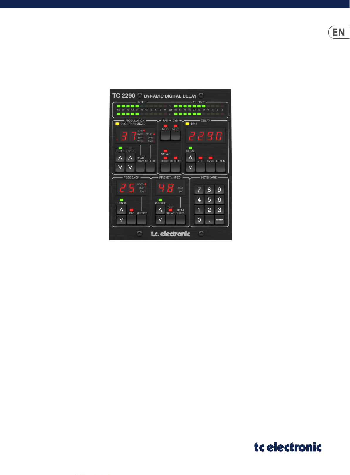
TC2290-DT
Legendary Dynamic Delay Plug-In with Dedicated Desktop Interface
and Signature Presets
2018- 04-25, R ev. 1.1
Page 2

2 TC2290-DT User Manual
Table of Contents
Important Safety Instructions ...................................... 3
Legal Disclaimer ............................................................. 3
Limited warranty ............................................................ 3
1. Introduction ............................................................... 4
2. Plug-in Installation .................................................... 4
2.1 Installation on a PC ............................................................. 4
2.2 Installation on a Mac ......................................................... 4
3. Connection and Setup ............................................... 5
4. Hardware and Plug-in Controls ................................ 8
4.1 Hardware Controls.............................................................. 8
4.2 Plug-in Controls ................................................................ 10
5. Operation ................................................................. 12
5.1 Delay Parameters .............................................................. 12
5.2 Modulation Eects ........................................................... 13
6. Presets ...................................................................... 15
7. Hardware Unit Software Updates ......................... 16
8. Specications ........................................................... 17
9. Signal Flow Diagram ............................................... 18
Page 3
3 TC2290-DT User User Manual
9. Do not defeat the safety purpose of the polarized
20. Please keep the environmental aspects of battery
Important Safety Instructions
Terminals marked with this symbol carry
electrical current of sucient magnitude
to constitute risk of electric shock.
Use only high-quality professional speaker cables with
¼" TS or twist-locking plugs pre-installed. Allother
installation or modication should be performed only
by qualiedpersonnel.
This symbol, wherever it appears,
alertsyou to the presence of uninsulated
dangerous voltage inside the
enclosure-voltage that may be sucient to constitute a
risk ofshock.
This symbol, wherever it appears,
alertsyou to important operating and
maintenance instructions in the
accompanying literature. Please read the manual.
Caution
To reduce the risk of electric shock, donot
remove the top cover (or the rear section).
No user serviceable parts inside. Refer servicing to
qualied personnel.
Caution
To reduce the risk of re or electric shock,
do not expose this appliance to rain and
moisture. The apparatus shall not be exposed to dripping
or splashing liquids and no objects lled with liquids,
suchas vases, shall be placed on the apparatus.
Caution
These service instructions are for use
by qualied service personnel only.
Toreduce the risk of electric shock do not perform any
servicing other than that contained in the operation
instructions. Repairs have to be performed by qualied
servicepersonnel.
1. Read these instructions.
2. Keep these instructions.
3. Heed all warnings.
4. Follow all instructions.
5. Do not use this apparatus near water.
6. Clean only with dry cloth.
7. Do not block any ventilation openings. Install in
accordance with the manufacturer’s instructions.
8. Do not install near any heat sources such as
radiators, heat registers, stoves, or other apparatus
(including ampliers) that produce heat.
or grounding-type plug. A polarized plug has two blades
with one wider than the other. A grounding-type plug
has two blades and a third grounding prong. The wide
blade or the third prong are provided for your safety. Ifthe
provided plug does not t into your outlet, consult an
electrician for replacement of the obsolete outlet.
10. Protect the power cord from being walked on or
pinched particularly at plugs, convenience receptacles,
and the point where they exit from the apparatus.
11. Use only attachments/accessories specied by
themanufacturer.
12. Use only with the
cart, stand, tripod, bracket,
or table specied by the
manufacturer, orsold with
the apparatus. When a cart
is used, use caution when
moving the cart/apparatus
combination to avoid
injury from tip-over.
13. Unplug this apparatus during lightning storms or
when unused for long periods of time.
14. Refer all servicing to qualied service personnel.
Servicing is required when the apparatus has been
damaged in any way, such as power supply cord or plug
is damaged, liquid has been spilled or objects have fallen
into the apparatus, the apparatus has been exposed
to rain or moisture, does not operate normally, or has
beendropped.
15. The apparatus shall be connected to a MAINS socket
outlet with a protective earthing connection.
16. Where the MAINS plug or an appliance coupler is
used as the disconnect device, the disconnect device shall
remain readily operable.
17. Correct disposal of this
product: This symbol indicates
that this product must not be
disposed of with household
waste, according to the WEEE
Directive (2012/19/EU) and
your national law. This product
should be taken to a collection center licensed for the
recycling of waste electrical and electronic equipment
(EEE). The mishandling of this type of waste could have
a possible negative impact on the environment and
human health due to potentially hazardous substances
that are generally associated with EEE. At the same time,
your cooperation in the correct disposal of this product
will contribute to the ecient use of natural resources.
For more information about where you can take your
waste equipment for recycling, please contact your local
city oce, or your household waste collection service.
18. Do not install in a conned space, such as a book
case or similar unit.
19. Do not place naked ame sources, such as lighted
candles, on the apparatus.
disposal in mind. Batteries must be disposed-of at a
battery collection point.
21. Use this apparatus in tropical and/or
moderate climates.
LEGAL DISCLAIMER
MUSIC Tribe accepts no liability for any loss which
may be suered by any person who relies either
wholly or in part upon any description, photograph,
or statement contained herein. Technical specications,
appearances and other information are subject to
change without notice. All trademarks are the property
of their respective owners. MIDAS, KLARK TEKNIK,
LAB GRUPPEN, LAKE, TANNOY, TURBOSOUND,
TC ELECTRONIC, TC HELICON, BEHRINGER, BUGERA and
COOLAUDIO are trademarks or registered trademarks
of MUSIC Tribe Global Brands Ltd. © MUSIC Tribe Global
Brands Ltd. 2018 All rights reserved.
LIMITED WARRANTY
For the applicable warranty terms and conditions
and additional information regarding MUSIC Tribe’s
Limited Warranty, please see complete details online at
musictri.be/warranty.
Page 4
4 TC2290-DT User Manual
1. Introduction
Read this manual to learn how to install and use your TC Electronic TC2290 delay
unit. This manual is only available in PDF format from the TC Electronic website.
To get the most from this manual, please read it from start to nish, or you may
miss important information.
To download the most current version of this manual, visit the web page:
www.tcelectronic.com/Categories/c/Tcelectronic/Downloads
If you still have questions about your TC Electronic product after reading its
manual, please get in touch with TC Suppor t:
www.tcelectronic.com/brand/tcelectronic/support
Click ‘Next ’ to begin the installation. When installation is complete, click ‘Finish’.
2. Plug-in Installation
Visit www.tcelectronic.com/tc2290-dt/support/ to download the
installer le. The plug-in is free and can be installed on an unlimited number
of computers, but does require the TC2290 hardware unit to operate the main
parameters such as delay time.
Select the Mac or PC version and save the le to your hard drive. Use the correct
32 or 64 bit version that matches your operating system. The latest rmware for
the TC2290 unit will be included in the software as well.
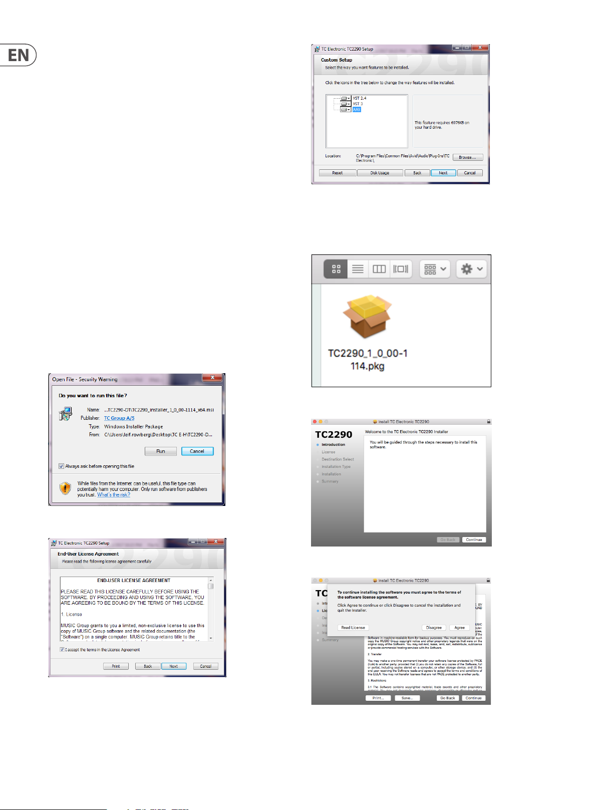
2.1 Installation on a PC
Open the zip le and double click the executable le. If you get a security
warning, click ‘Run’.
2.2 Installation on a Mac
Open the zip folder and double click the installer icon.
Proceed through the prompts to begin installation.
Accept the license agreement and click ‘Next’.
Select which VST and/or AAX components you want to install. Pro Tools uses
AAX and most other DAW programs use VST. The installer will oer a default
location to save the le, but you can choose another location by clicking
the ‘Browse’ button.
Click ‘Continue’ and accept the license agreement.
A default location will be selected for installation, or you can select another
folder manually. If you have administrator authorization in place, you will need to
enter your password before beginning installation.
Page 5
5 TC2290-DT User User Manual
3. Connection and Setup
Getting the TC2290 up and running couldn’t get any easier. Plug the included
USB cable into the unit’s rear micro-USB port, and connect the other end to a free
USB port on your computer. The TC2290 is bus powered so no other power cables
are necessary, and no additional drivers need to be manually installed.
The TC2290 is built to work with a USB hub, but not all hubs are supported. If the
TC2290 fails to power on or doesn't connect to the plug-in, try connecting
directly to a USB port instead of the hub.
TC2290
Laptop
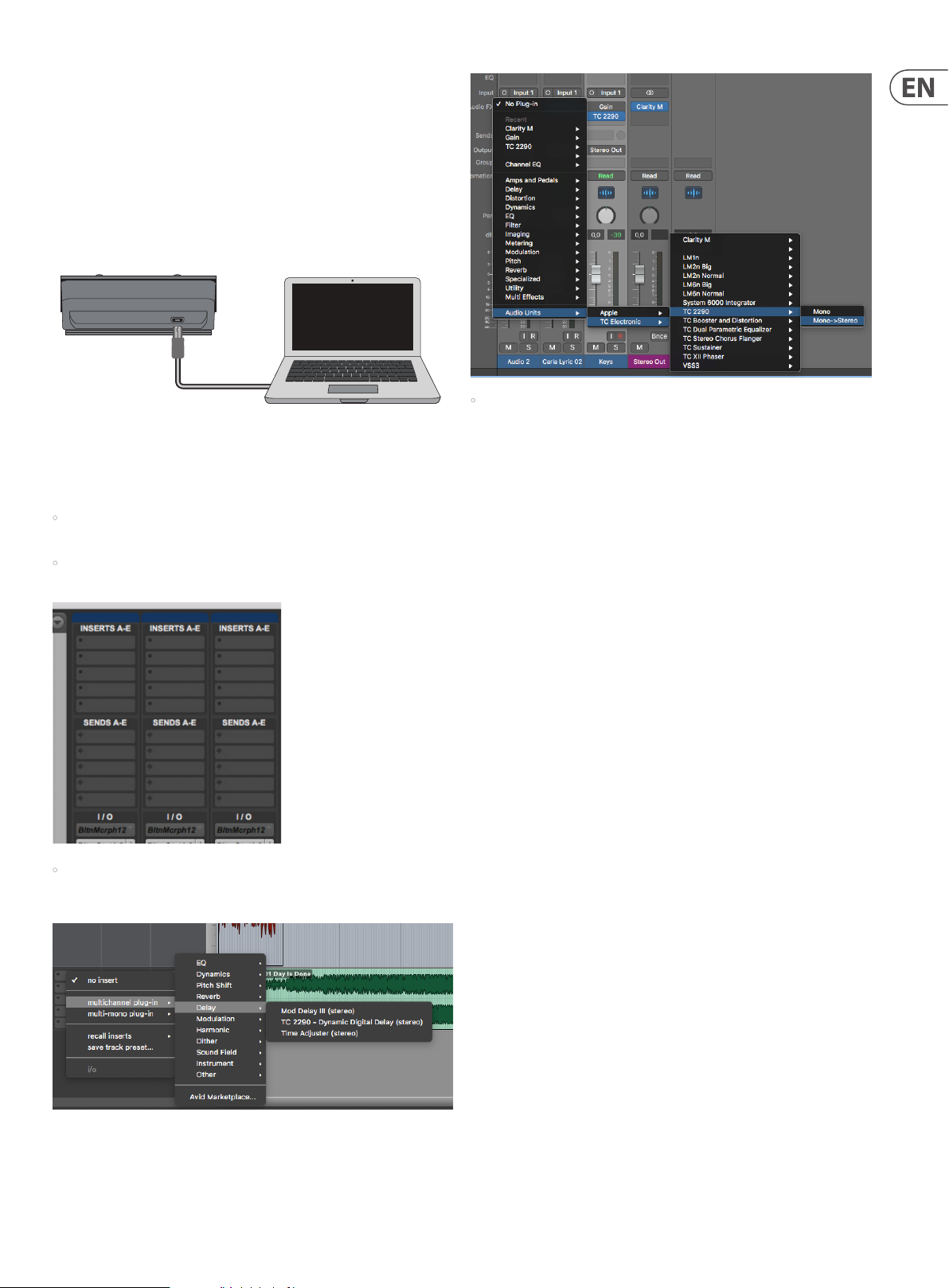
The TC2290 should light up upon successful connection. You can now apply the
plug-in to a channel in your DAW to begin using the eect. This process may vary
slightly depending on your software, but generally should require these steps:
• Select a channel or bus in your DAW to which you would like to
add the eect.
• Access the mixer page where you should see a section dedicated
to eect slots.
• The plug-in will likely be found in a dedicated TC Electronic folder. Select the
TC2290 and it will now be added to the signal chain.
Insert vs Aux Eect
The TC2290 can be inserted directly into an eect slot on a single channel,
as described above, which passes the entire signal through the eect. In this
case, note that the direct input signal becomes mono before it is panned,
either statically or modulated. This occurs when the PAN/DYN section DIRECT
button is engaged.
However, the TC2290 can also be added to an auxiliary bus, and one or more
channels can send a portion of their signal to this bus to be processed by the
eect. The output of the eect is then mixed back in with the rest of the tracks.
This diers from an insert eec t in that the TC2290 isn't aecting the track's
entire signal, so the direct signal cannot be modulated using the MOD buttons
in the PAN/DYN section. In this setup, the Mix parameter should always be
set to 100%.
Mono/Stereo Operation
The TC2290 can be used both as a mono instance on mono tracks and a stereo
instance on stereo tracks. Depending on the specic DAW, a mono in/stereo out
may also be available.
In the case of a mono out instance, the output signal is made by outputting the
left plug-in channel only. In this case, panning should not be used.
• Open the menu where you can select from a list of eect types, which
probably includes many stock plugins that are included with the DAW.
There should be a submenu to view general VST/AU/AAX options.
Demo Mode
If the plug-in is installed without a hardware unit connected, the plug-in will
default to demo mode. In this state, sound is processed but no controls
are available. Once a hardware unit is connec ted, all controls become available.
If the hardware unit is disconnected, automation and preset recall will still be
available for 2 weeks, after which the plug-in goes into demo mode.
Page 6

6 TC2290-DT User Manual
Connection Modes
After you have installed the plug-in and connected the TC2290 via USB, you can
begin adding the eect to your tracks. Adjustments to the eect are done with
2 sets of parameters:
Primary – the parameters that are adjusted on the physical unit. These include
common items such as delay time and feedback.
All of these parameters will be discussed in detail later in this manual.
Supported DAWs
The plug-in is available in these formats:
• VST2.4 (Ableton, Cubase, Nuendo, Reaper, Audition, most others)
• VST3 (Ableton, Cubase, Nuendo, Studio One)
• AU (Logic, Ableton)
• AAX (Pro Tools)
The following DAWs have been specically tested to work with the
TC2290 plug-in:
• Pro Tools
• Logic Pro
• Cubase
• Ableton Live
• Studio One
• Nuendo
• Reaper
• Reason
• Garage Band
However, the plug-in is not necessarily limited to the hosts on this list.
Most modern DAWs can make use of at least one of the four formats provided.
Visit the product page on tcelectronic.com to see the latest supported DAWs.
Secondary – the parameters adjusted in the plug-in UI window. The secondary
parameters are the ones that were known as “SPEC KEYS” (Special Keys) on the
original 2290. These parameters can be called from the hardware unit using
the SPEC KEYS.
Page 7

7 TC2290-DT User User Manual
Connection Status
Connection status is indicated on the lower lef t side of the plug-in window.
Successful connec tion is indicated with a green chain icon.
There are 3 conditions that will result in a “Not connected” status. If another
instance of the plug-in already exists on another track, the chain icon will appear
yellow with a yellow frame, and the text box will notify you where the plug-in is
currently active. Click the chain icon to connect the hardware unit to the new
plug-in location. The yellow icon may also appear while the connection is being
made between the TC2290 unit and the plug-in, accompanied by
“Connecting...” text.
To summarize the connection status possibilities:
If the hardware unit is disconnected from the computer, but the countdown has
not yet expired, a yellow chain icon without the yellow frame will appear. See
“Demo Mode” section for details.
All other “Not connected” states are indicated by a red chain icon. This could
happen if the USB cable is disconnected, the TC2290 connection is disrupted,
or other issues.
Most DAWs oer the ability to move or drag plug-ins from one track/bus to
another, and TC2290 supports this as well.
Most DAWs also feature an on/o switch for plug-ins, accessible inside the
plug-in window and/or the track itself. Muting the plug-in will make the eect
inaudible, but will not shut down the connection to use the hardware unit.
Page 8
8 TC2290-DT User Manual
4. Hardware and Plug-in Controls
Control of the TC2290 is divided between the hardware unit and the plug-in
window. All commonly-used parameters of the 2290 are accessible through the
hardware device. These include parameters that control major parts of the eect,
such as delay time, modulation, preset changes, mix (via 'Special' control) and
much more. Secondary parameters that are needed less often are handled in the
plug-in window. These are parameters like modulation thresholds, subdivision,
preset save and more.
4.1 Hardware Controls
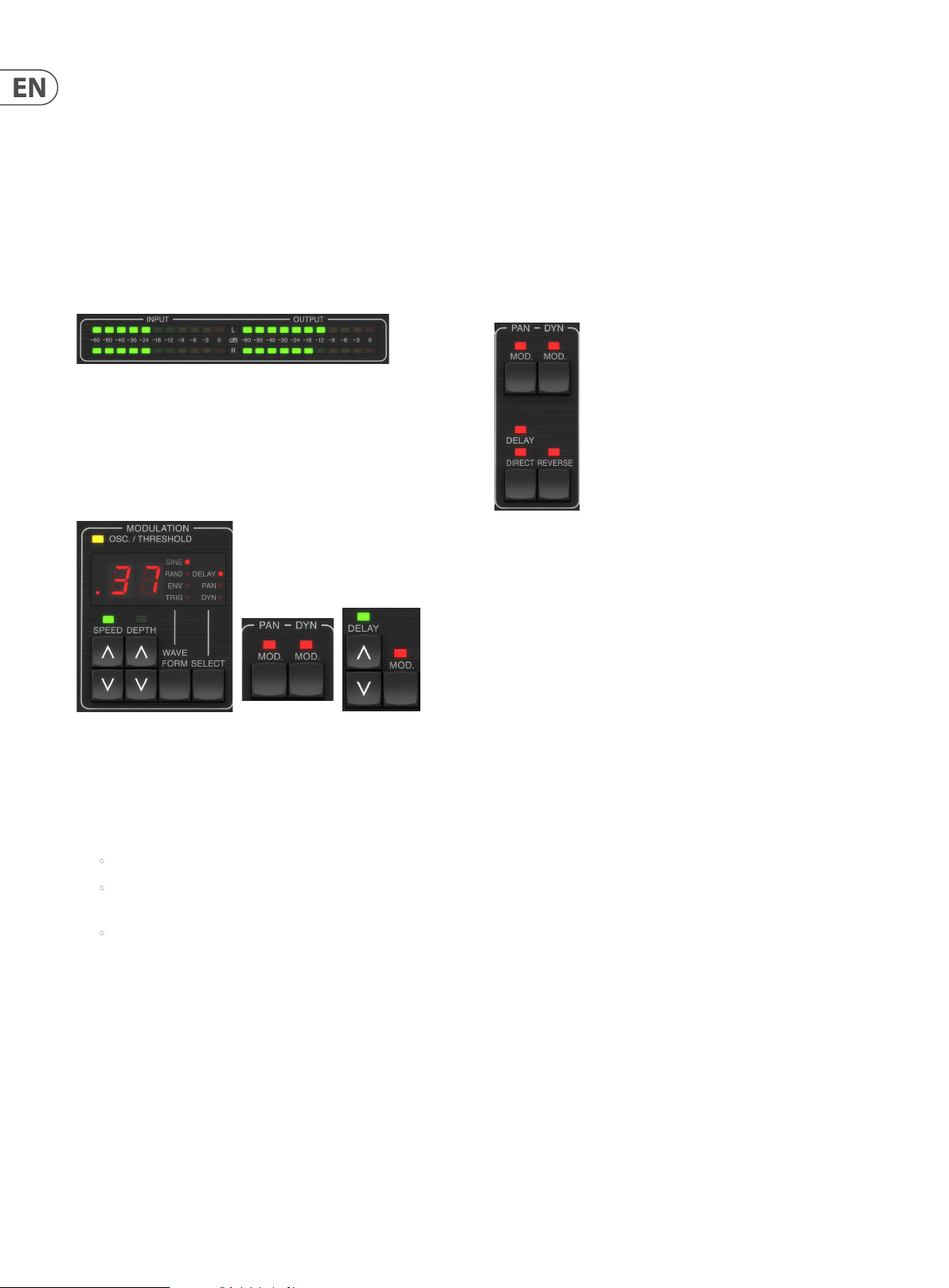
Meters
The meter section gives feedback about the incoming and outgoing audio
signals. The input level displays the audio as it enters the plug-in, and is not
aected by adjustments to the input level control or any other parameter.
The output meter is aected by the results of the eect as well as the output
level control parameter.
MODULATION
DEPTH – Pressing UP or DOWN once will bring focus to the DEPTH parameter,
and additional presses will move the value by one step. The DEPTH value is
displayed in percentage of maximum modulation.
Pressing the SPEED or DEPTH arrow keys will rst bring focus to that parameter,
which also allows a specic value to be entered on the KEYBOARD, followed by
the ENTER key. When either parameter is active, a green LED will ash above and
the display will show the current value.
The yellow OSC/THRESHOLD LED in the upper left corner of this section shows
modulation speed when using periodic modulations (SINE, RANDOM) and
indicates when the input level passes the threshold for ENV or TRIG eects.
PAN/DYN
Press either of the MOD buttons beneath the PAN and DYN labels to engage those
functions respectively. The red LEDs above each button indicate the on/o status.
The parameters for each eect are adjusted in the MODULATION section.
This section controls parameters of the modulation eects. Note that the
modulation is actually engaged with the MOD buttons located in the PAN,
DYN and DELAY sections.
Pressing the SELECT button scrolls through the parameter sets for the DELAY,
PAN and DYNAMICS, essentially selecting the focus of the other buttons in this
section. The types of modulation eects include:
• Delay time modulations – chorus, anger, pitch, auto-doubling.
• Pan position modulations – auto-panning of the direct signal, delay
signal, or both.
• Dynamic modulation – tremolo, delay compressor/expander, ducking
and gating.
Each of these parameter sets consists of the following values:
WAVEFORM – determines the modulation waveform, bet ween sine wave (SINE),
random wave (RAND), input signal envelope controlled (ENV), or input level
triggered (TRIG). The modulation target determines the function of ENV and TRIG.
The DELAY/DIRECT button determines if the PAN eect is applied to the delay
signal only, the direct signal only, both or neither. This also applies to the static
pan set in the plug-in, so if neither DELAY nor DIRECT is lit, there is no panning at
all.
When neither DELAY nor DIRECT is lit, the delay signal is phase inverted in the
right channel. This is nice for creating wide chorus/anger eects, but may not
be desired for delay eects. To circumvent this, set PAN in the plug-in to 50,
disengage PAN MOD, and enable PAN DELAY (not DIRECT). This will give the same
result minus the phase inverse of right delay signal.
Note that whenever DIRECT is lit, the direct signal will rst be summed to mono
and then panned. When DIRECT is not lit, the direct signal will be stereo (if the
plug-in is a stereo instance).
The REVERSE button causes the selected Dynamic eect to function in an
opposite way. With the Waveform set to SINE or RAND, a tremolo eect is
achieved which produces a modulated increase/decrease in volume. When the
REVERSE button is activated, this creates a modulation that enhances delay
volume when direct volume is suppressed and vice versa.
With the Waveform set to ENV or TRIG, the REVERSE button changes the usual
Compression/Ducking eects into Expansion/Gating eects.
SPEED – Pressing UP or DOWN once will bring focus to the SPEED parameter,
and additional presses will move the value by one step. The SPEED parameter
is shown in Hz (cycles per second). Depending on the modulation target,
when the ENV or TRIG Waveform is selected, the parameter controls the speed
from no eect to maximum eect. A setting of “1” means a ramp time of 1
second, whereas a setting of “5” means a ramp time of ⁄ of a second.
Page 9
9 TC2290-DT User User Manual
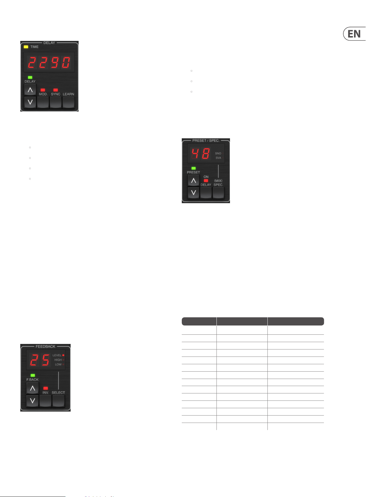
DEL AY
The main function of this section is to control the delay time. The yellow LED
above the display will ash in rhythm with the current tempo, and the exact time
in ms will be displayed. There are several ways to adjust the delay time:
• Using the UP/DOWN arrows
• Using the KEYBOARD (after pressing UP/DOWN arrows once)
• Pressing the LEARN button in rhythm with your desired tempo
• Pressing the SYNC button to synchronize the tempo with the
DAW tempo
A single press of the UP or DOWN arrow keys will bring focus to the delay
tempo setting. Doing so causes the green LED to ash, and the tempo can now be
adjusted. Pressing UP or DOWN will change the tempo by single digit increments,
or holding the button will allow the parameter to scroll quickly.
However, once the green LED is ashing, the KEYBOARD can also be used to
manually enter a delay time, followed by the ENTER key. If you use the KEYBOARD
to enter the delay time, please note that you can enter values with decimals,
including values below one millisecond by pressing the dot. For example, a delay
time of 8.5 ms can be dialed by pressing [8] [dot] [5] [ENTER].
If you don’t know the exact tempo measurement for your desired tempo, you can
get fairly close by tapping the LEARN button in rhythm. The time between the
rst and second press will used as the new tempo.
The TC2290 can also follow the tempo currently set in your DAW. Press the SYNC
button to enable this. Once enabled, the UP and DOWN buttons will change the
subdivision of the beat.
To enable modulation of the delay signal, press the MOD button. See the
MODULATION section in this chapter as well as Chapter 5 for details.
FEEDBACK
This section primarily controls the number of delay repeats, but it also aects
other functions.
Pressing the UP or DOWN arrow but tons will activate the adjustment for the
selected parameter, causing the green LED to ash. Further presses will change
the value by one step, or holding the but ton will scroll rapidly. With the green
LED ashing, an exact value can be entered on the KEYBOARD, followed by the
ENTER button. The possible values for the 3 parameters are as follows:
• Feedback – 0-99%
• High cut – 2, 4, 8, 33 kHz (33 kHz = o)
• Low cut – 0, 0.1, 0.2, 0.4 kHz (0 = o, 0.1 = 100 Hz, etc.)
Pressing the INV button inverts the feedback signal, which may not be noticeable
with echo eects, but is more pronounced when applied to modulation
such as anger.
PRESET/SPEC
Pressing the DELAY ON button toggles the delay eect on and o, indicated by
the red LED. However, after turning this switch o, the direct signal is still heard
along with any panning eec ts. Note that the static pan position (set by PAN in
plug-in) is only used when DELAY ON is not lit when Spec key 26 (MUTE) is set to
0 (IN). Otherwise (Spec 26 non-zero), the direct pan position is center.
Pressing the UP or DOWN arrow once will engage the preset selection, allowing
presets to be scrolled one-by-one, or a specic preset can be entered on the
KEYBOARD, followed by the ENTER button. See Chapter 6 for details.
The SPEC (Special) button allows control of some parameters that are otherwise
only accessible in the plug-in window. Pressing the SPEC button accesses the
Special Number (SNO) and the Special Value (SVA). The Special Number can
only be entered on the KEYBOARD, followed by the ENTER button, whereas
the Special Value can be entered with the KEYBOARD or preset arrow keys.
The following chart shows the available parameters that can be controlled:
Special Number Parameter Possible Values
1 Input Level 0-99 (o – 0 dB)
2 Delay Mix (default) 0-99%
3 Output Level 0-99 (o – 0 dB)
4 Pan 0-99
5 Invert De lay 0 (o), 1 (on)
6 DAW Sync Subdivision 0-6 (64t h note – whole note)
7 DAW Sync Mode 0 (straigh t), 1 (d otted), 2 (triplet)
8 Delay Deep M od 0 (o), 1 (on)
9 Invert De lay Mod 0 (o), 1 (on)
10 Delay Mod Th reshold 1-9
11 Pan Mo d Threshold 1-9
12 Dynam ic Delay Volume 1-9
13 Dynamic Feedback 1-9
26 Mute Method 0 (In), 1 (Out), 2 (Both)
Pressing the SELECT button scrolls through the 3 adjustable parameters in this
section – feedback LEVEL, HIGH cut, and LOW cut lters. The display will indicate
the current selec tion as well as the value for that parameter.
Page 10
10 TC2290-DT User Manual
Knowing that DELAY MIX will likely be the most common plug-in parameter that
users will need to access regularly, this has been programmed as the default
Special Number. As soon as the SPEC button is pressed, Special #2 (DELAY MIX)
will appear as the SNO entry, and the SPEC button can be pressed again to toggle
focus to the DELAY MIX value (SVA). Use the arrow keys or KEYBOARD to enter the
desired value. Press SPEC again to return to the normal preset select state.
To access a Special number other than DELAY MIX, press the SPEC button until
SNO is highlighted with a red LED. Dial the desired Special Number on the
KEYBOARD and press ENTER, which will automatically toggle the SPEC focus to
Special Value (SVA). Dial the value using the UP/DOWN arrows or the KEYBOARD.
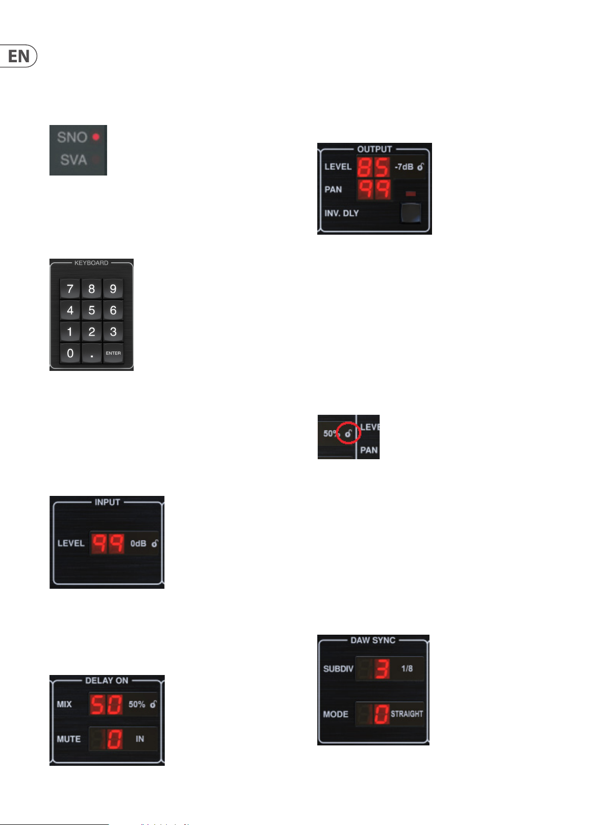
KEYBOARD
Click and drag the MIX parameter to adjust the balance between the direct and
delay signals.
Click the right side of the MUTE mode parameter to select whether muting
aects the input or output signals, or both. Muting the input will allow the echo
tail to fade naturally af ter the eect is bypassed.
OUTPUT
Click and drag up or down to adjust the output level from 0 to 99. A setting of
0 is -∞, and a setting of 1 is -96 dB. The level increases in 3 dB increments at
lower settings, and by 0.5 dB increments above -40 dB.
Adjust the pan position of the signal by clicking and dragging the PAN parameter.
Panning is only applied to signals chosen with the DELAY/DIRECT button in the
PAN section of the hardware unit. With a setting of 50, both the direct and delay
signals are centered. A setting of 0 places the direct signal hard right and delay
hard left. A setting of 99 places the direct signal hard left and the delay signal
hard right.
The KEYBOARD section is used to enter specic values or presets instead of
scrolling with arrow buttons. Generally, when entering a specic value, the green
LED associated with that parameter section must be ashing in order for the
KEYBOARD to take eect. After a value has been chosen, press the ENTER button
to conrm.
4.2 Plug-in Controls
INPUT
Click and drag up or down to adjust the input level from 0 to 99. Alternatively,
double click on the numeral to enter a value manually. A setting of 0 is -∞,
and a setting of 1 is -96 dB. The level increases in 3 dB increments at lower
settings, and by 0.5 dB increments above -40 dB.
DEL AY ON
When the INV DLY button is activated, the output of the delay signal is
phase inverted.
Lock Symbol
Some of the parameters can by locked from being recalled when a new preset
is selected. Locked parameters will always keep their values no matter which
preset you recall.
A great example of use is using it with the MIX parameter.
The default presets provided in the plug-in are typically created with the intent
that the eect will be inserted on the track (as an insert eects). A MIX value has
been chosen that will work for that preset.
However, if you’d like to use the TC2290 as a send/parallel eect, the MIX
parameter should typically be set to 100%. After setting the MIX to 100%, use
the lock function to make sure it stays at 100% even if you load another preset.
DAW SYNC
Page 11

11 TC2290-DT User User Manual
When the DAW SYNC selection is active (by pressing the SYNC button on the
unit), some parameters can be adjusted to control the relationship between the
delay and the DAW tempo.
The delay subdivision (SUBDIV) can be set anywhere from 1/64th note to a whole
note. Note that this can also be adjusted using the arrow buttons in the DELAY
section on the unit.
The subdivision can also be heard in straight time, dotted, or triplet feel by
adjusting the MODE set ting.
DEL AY MOD
When engaged, the INV DLY MOD button inverts the anger sweep start and
the envelope pitchshift direction. This only applies to Delay Mod Waveforms
ENV and TRIG.
Engage the DEEP MOD by pressing the but ton. DEEP MOD disables the automatic
modulation depth mapping known as “Golden Ratio”. This makes it possible
to do much deeper modulation with wild pitch shifts, but it is somewhat
uncontrollable.
THRESHOLDS
PRESET
Use the PRESET section to recall and save presets as well as assigning them
as favorites. See Chapter 6 for details.
Bottom section
The bottom portion of the plug-in window displays connection status as well as
plug-in instance name, and has several options available.
The green chain icon indicates successful connection between the hardware
unit and the plug-in. Connec tion issues will be indicated by yellow or red icons;
see Chapter 3 for details.
The current name of the plug-in instance appears in the middle eld. If the DAW
is able to provide the name of the track where the plug-in instance is inserted,
the plug-in instance will be named after the track name. The instance can be
renamed by clicking the pencil icon.
If you install the plug-in without connecting the hardware unit to your computer,
a red dot will appear on the shopping cart icon. This will link you to more
information about buying the TC2290 unit. Once the plug-in detects a connected
hardware unit, the red dot will disappear.
All 4 of these items oer 9 threshold settings for their respective parameter.
Range for each parameter is 1-9.
DLY MOD – Delay ENV and TRIG waveforms.
PAN MOD – Pan ENV and TRIG waveforms.
DYN DLY VOL – Determines the threshold for the volume modulation of the delay
(and direct for ENV REVERSE) signal when DYN modulation is ENV or TRIG.
DYN FB – Determines the threshold for the modulation of the feedback level
when DYN modulation waveform TRIG is selected (not ENV).
These set the thresholds associated with the Envelope (ENV) and Trigger (TRIG)
modulation forms. The higher the value, the higher input signal is necessary
to get the same modulation eect. Delay, Pan and Dynamic thresholds are
adjustable in 3 dB steps. The OSC./THRESHOLD LED indicates the current
operating state, and can therefore be used as help for setting the threshold.
The Settings icon accesses a menu with several links and options. This user
manual is available, along with links to the TC Electronic website, relevant news,
additional signature artist presets, and the user license agreement. If a red dot
appears over the Settings icon, a new version of the plug-in or rmware may
be available. Click “Check for Updates” to download and install the new le.
See Chapter 7 for details.
With the “Help” option selected, hovering the mouse over a certain item in the
plug-in window will give a brief description of the parameter’s function and the
Special key number (if applicable).
With the “Take over on focus” option selected, the currently viewed plug-in
instance will take over control of the physical hardware unit as soon as it is
brought into focus.
Also, when a new instance of the plug-in is inserted on a track or bus, that
instance will take over immediately.
Page 12

12 TC2290-DT User Manual
5. Operation
This chapter will discuss the details of creating certain eects and how to adjust
each parameter. After you have connected the hardware unit to your computer
and have the plug-in inserted in a channel or bus, you are now ready to start
experimenting with the capabilities of the TC2290. The default presets and
signature presets may be a good place to start to get an idea of what is possible.
In the plug-in window, click the current preset name, then navigate to ‘Original
2290 Presets’ or ‘Signature Presets’. You either need to send live audio to the
plug-in, or apply the eect to a prerecorded track.
On the hardware unit, in the PRESET/SPEC section, make sure the DELAY ON
button is active (LED lit). Most of the signicant eect parameters are accessed
on the hardware unit, so we’ll focus attention there.
5.1 Delay Parameters
The TC2290 is, rst and foremost, a delay unit, so we can start with the
3 main parameters:
• Delay time – This controls the rate of the echoes.
• Feedback – This controls how many echoes are heard.
• Mix – This adjusts the volume balance between the delay echoes and
the direct signal.
Delay Time
If you don’t know the exact tempo measurement for your desired tempo, you
can get fairly close by tapping the LEARN button in rhythm. The time between
the rst and second press will used as the new tempo. You can see on the display
that the rst press causes the numbers to start from 0 and ascend very quickly
(these are milliseconds after all). If you do this several times, you may notice that
you get a slightly dierent result each time, so the tempo may still need to be
tweaked manually using the arrow buttons.
The TC2290 can also follow the tempo currently set in your DAW. Press the SYNC
button to enable this. Let’s say your DAW tempo is set to 120 BPM, which tends to
be the default set ting in a new project/session.
Press the SYNC button, and the TC2290 will convert the tempo into ms,
which is 250.
Once SYNC is enabled, the UP and DOWN but tons will change the subdivision of
the beat. The subdivision is currently set to eighth notes in the DAW SYNC section
of the plug-in window, which gives us 250 ms at 120 BPM.
If you select a default preset that uses delay (#80 for example), you’ll see that the
yellow TIME LED above the DELAY display will ash in rhythm with the current
tempo, and the exact time in ms will be displayed.
There are several ways to adjust the delay time:
• Using the UP/DOWN arrows
• Using the KEYBOARD (after pressing UP/DOWN arrows once)
• Pressing the LEARN button in rhythm with your desired tempo
• Pressing the SYNC button to synchronize the tempo with the current
DAW tempo
A single press of the UP or DOWN arrow keys will bring focus to the delay
tempo setting. Doing so causes the green LED to ash, indicating that the
tempo can now be adjusted manually.
This can be changed to quarter notes by pressing the UP button in the DELAY
section of the hardware unit, or making the change in the DAW SYNC section of
the plug-in window. Making a change to one will cause the other to be altered as
well. Change the subdivision to quarter notes, and you now have a delay
time of 500 ms.
Even with DAW SYNC enabled, the LEARN button can still be used to set the
tempo. When this is done, the TC2290 will grid to the nearest subdivision and
mode (Straight, Dotted, Tripled) within the DAW-synced tempo, and set the
delay time accordingly.
FEEDBACK
Feedback controls the number of echoes that are created by the eect.
Pressing UP or DOWN will change the tempo by single digit increments, or
holding the button will allow the parameter to scroll quickly. However, once the
green LED is ashing, the KEYBOARD number pad can also be used to manually
enter a delay time, followed by the ENTER key.
Press the SELECT button until the LED next to LEVEL is lit. This ensures that we are
adjusting the feedback parameter and not the high or low cut lters.
Pressing the UP or DOWN arrow but tons causes the green LED in this section
to ash. We can now adjust the feedback parameter, either by pressing or
holding the UP/DOWN buttons, or by entering a value with the KEYBOARD
followed by the ENTER key.
Page 13

13 TC2290-DT User User Manual
MIX
The last parameter to adjust a basic delay setting is the MIX between the echoes
and the direct signal. To access this parameter, press SPEC twice and use the
UP/DOWN arrows to set the MIX.
Alternatively, the MIX setting can be adjusted using the plug-in UI.
If using the plug-in as an insert on a channel, you will likely want a setting
below 50% to avoid a muddy-sounding result. However, if using the plug-in as a
send/aux eect, set the MIX to 100%.
5.2 Modulation Eects
SPEED – Pressing UP or DOWN once will bring focus to the SPEED parameter,
and additional presses will move the value by one step. The SPEED parameter is
shown in Hz (cycles per second).
Depending on the modulation target, when the ENV or TRIG Waveform is
selected, the SPEED parameter controls the rate of change from no eect to
maximum eect. A setting of “1” means a ramp time of 1 second, whereas a
setting of “5” means a ramp time of ⁄ of a second.
DEPTH – Pressing UP or DOWN once will bring focus to the DEPTH parameter,
and additional presses will move the value by one step. The DEPTH value is
displayed in percentage of maximum modulation.
Pressing the SPEED or DEPTH arrow keys will rst bring focus to that parameter,
causing a green LED to ash above and the display to show the current value.
This means the arrow buttons can change the value by single steps, and also
allows a specic value to be entered on the KEYBOARD, followed by the
ENTER key.
Note- the feedback parameter of the delay may also have an eect on
modulation eects.
Each of these parameters aects the sound dierently depending on the
specic eect. Let’s review each type of modulation and how it can be adjusted.
5. 2.1 Dynamic Eects
In the MODULATION section, use the SELECT button to highlight the
Dynamics (DYN) parameters. Ensure that the MOD button is engaged in the
center PAN/DYN section.
The TC2290 has 3 kinds of modulation eects available:
• Delay Time modulations – chorus, anger, pitch modulation,
auto-doubling eects.
• Dynamic modulations – tremolo, compress/expand,
ducking/gating eects.
• Pan position modulations – auto-panning eects.
Each of these eects has its own MOD on/o button.
The parameters for each of these modulations are controlled in the MODULATION
section on the hardware unit. By using the SELECT button within this sec tion,
you can scroll through the 3 types of modulation.
Ducking Delay
A ducking delay uses the input signal to attenuate the delay signal, causing the
echoes to stay “out of the way” while you’re playing, but still allow the echo tails
to be audible during gaps in your playing.
Press the WAVEFORM button until TRIG is selec ted. This selects the
ducking eect.
Press the DEPTH UP or DOWN button to shift focus to this parameter. The green
LED will ash above and the current value is displayed. This parameter controls
how much the delay signal is attenuated. Lower the value for small amounts of
attenuation, or raise it to make the eect almost inaudible while you’re playing.
Press the SPEED UP or DOWN button to shif t focus to this parameter. This controls
the rate at which the attenuation is released. Lower values allow a longer period
of time to pass after you stop playing before the echoes increase to their normal
volume. Higher values let the echoes come in quickly.
Gated Delay
By pressing the REVERSE button in the PAN/DYN section, the ducking eect
becomes a gated delay. Set this way, the eect will only be heard while you
are playing, and will be attenuated when you stop.
After the modulation type has been selected, the 3 parameters in this section can
be adjusted, which are:
WAVEFORM – determines the modulation waveform, between sine wave (SINE),
random wave (RAND), input signal envelope controlled (ENV), or input
level triggered (TRIG). The modulation target determines the function of
ENV and TRIG.
Tremolo Eect
Press the WAVEFORM button until SINE or RAND are selected. This creates
a tremolo eect where the volume of both the direct and delay signals are
attenuated and then return to full volume, up and down at a constant rate
(SINE only). Use the SPEED parameter to adjust the specic rate, and the DEPTH to
adjust the amount of attenuation.
Page 14

14 TC2290-DT User Manual
By engaging the REVERSE button, the direct signal and delay signal are
attenuated opposite one another, with the direct reaching full volume while the
delay is at maximum attenuation, and vice versa.
Compressor/Expander Eect
Press the WAVEFORM button until ENV is selected. This produces a compressed
delay sound similar to the ducking eect, but less pronounced and leaves the
feedback unaected.
Engaging the REVERSE button produces an expander eect that aects the direct
and delay signals. Initial transients are attenuated, creating an ‘attack-kill’ eect.
The SPEED parameter controls how quickly the volume swells to normal level, and
the DEPTH parameter controls the amount of initial attenuation.
5.2.2 Chorus/Flanger/Doubling Eects
In the MODULATION section, use the SELECT button to highlight the DELAY
parameters. Ensure that the MOD button is engaged in the DELAY section.
Several types of modulation can be achieved by setting very short delay times,
which are not heard as an echo, but rather as an extra, synchronized voice.
Some common delay and feedback levels are outlined here:
Delay Time Eect MOD butt on
0-1 0 Flanger ON Very High 50
5-50 Chorus ON Slight or none 50
20-80 Dou ble Tr ack ON Slight or none 50
100- up Delayed Chorus ON Set for repeat s 50
Feedback
Setting
Mix
The ENV setting produces a ramp that starts and stops with the input level.
Higher SPEED settings and moderate DEPTH settings might be necessary.
Selecting TRIG creates a sine sweep that stops whenever the input signal stops.
This allows the sweep to be synchronized along with the music.
Auto Doubling
This eect is a specic type of chorus that gives the impression of 2 identical
players/singers performing the same part in unison. Try low DELAY times around
20-80 ms, low FEEDBACK setting, slight pitch shift, slight volume modulation,
and changes in panning position. This eect requires all 3 MOD buttons to be
active.
Default presets 95 and 97 and good examples of this eect, so starting with
those settings would be wise.
5.2.3 Panning Eects
In the MODULATION section, use the SELECT button to highlight the PAN
parameters. Ensure that the MOD button is engaged in the center PAN/DYN
section.
The panning eect can be applied to the direc t signal, the delay signal, both or
neither. This is selected using the DELAY/DIRECT button in the PAN/DYN section.
Pressing repeatedly toggles through the 4 possible settings. One of the LEDs must
be lit in order for any panning eects to be heard.
Chorus
Chorus eect is achieved my mixing the direct signal with a modulated delay
signal. The result is a multi-voice character that sounds like more than one
instrument playing in unison, with small variations in pitch and time.
In the DELAY section, set the time very low – around 20-25 ms. In the FEEDBACK
section, reduce the level all the way to 0.
Press the WAVEFORM button to select SINE, which is very common for
Chorus eects. Other waveforms will be discussed later in this chapter.
In the MODULATION section, ensure that DELAY is selected, and adjust the DEPTH
parameter to control the intensity of the eect. Higher values create a deeper
detune. Adjust the SPEED parameter to control the rate of the modulations.
Note that setting the MIX control to 99 produces a pure vibrato eect, where the
pitch is modulated up and down without the direct signal to create the 2 voices.
Flanger
Flanger eects produce sweeping wave-like modulations that create a thick,
often psychedelic sound. This will operate similarly to the chorus eect, with a
few adjustments.
In the FEEDBACK section, raise the feedback level parameter to 50. The higher the
feedback setting, the more resonant the anger eect will be. Settings below
90 are recommended.
For classic jet anger eects, set the DELAY time around 2 ms.
In the MODULATION section, try setting the SPEED parameter very low to make
the sweeps slower. Increasing the DEPTH parameter produces wider sweeps.
The xed pan position can be adjusted in the plug-in window using the PAN
control in the OUTPUT section. When DELAY/DIRECT is selected, a setting of
50 is centered, 0 is far right, and 99 is far left for the direct signal, and the delay
signal will be the opposite.
Pressing the PAN MOD button, you will hear audio traveling from one speaker to
the other, depending on the setting on the DELAY/DIRECT button.
In the MODULATION section, select the SINE waveform, then use the SPEED
parameter to adjust how quickly the audio is panned back and forth.
The DEPTH parameter adjusts how wide the panning eect drifts from left to
right and back. A set ting of 99 will pan fully to either side, while a setting of
50 only goes half way before changing direction again.
Selecting the ENV waveform causes the static pan position to switch each time
the signal falls below the threshold. If both the DELAY and DIRECT signals are
selected for the eect, they trade sides. Fairly fast SPEED settings and high DEPTH
setting are more eective for this sound.
The TC2290 can be used as an autopanner on the direct signal only by setting the
MIX control in the plug-in window to 0.
Other Waveforms
Though the SINE option will give you recognizable chorus and anger sounds,
there are other eec ts achievable with dierent waveforms. The RAND setting
will yield a random sweep instead of the continuous form of the SINE.
Page 15

15 TC2290-DT User User Manual
6. Presets
The TC2290 oers a collec tion of default and signature presets, as well as the
option to create and save your own custom settings.
Note that most DAWs have a built-in preset function that appears on every
plug-in, which is often found at the top of the plug-in window.
It is not recommended to use this as your primary method of saving presets as it
has limited functionality and does not allow the saved presets to be transferred
easily to other DAWs. Instead, we suggest using the included Preset section at the
bottom of the window:
A single click on the PRESET window brings up a menu with several presetrelated options. Recall a factory or user preset from the libraries, save the current
preset, or create a new user preset with the 'Save as' option.
Factory and Signature presets have unique icons that appear next to the
preset name.
When recalling a default or saved preset, the name will appear in plain text
as shown. However, as soon as you make an alteration to any of the parameters
in that preset, the tex t changes to italics to indicate a deviation. This is also
indicated by a red dot after the preset number on the hardware unit and in the
plug-in window. You can click in the PRESET window, then select the Save option,
or discard the changes when you navigate away from that preset.
Presets can also be recalled from the hardware unit in the PRESET/SPEC section.
The presets menu is divided between a Factory Presets and
a User Presets section.
The Factory Presets are built into the plug-in and cannot be overwritten, so if a
factory preset is modied and you'd like to keep the changes, you need to save it
as a user preset. User Presets can be edited and organized as you’d like.
The Factory Presets section includes a sub-section called Signature Presets.
Signature Presets are custom-made presets designed by world-class artists
and recording engineers. The library of signature presets is constantly being
expanded, and you can check for more Signature Presets that might be available
for download by accessing the Settings menu and selec ting ’Signature Presets’.
Pressing the preset UP or DOWN arrow buttons shifts the focus to that section,
causing the green LED to ash. You can now press the UP and DOWN buttons to
scroll through presets one slot at a time, or use the KEYBOARD to enter a specic
preset number, followed by the ENTER button.
Favorite Preset
Creating your own presets will make them accessible from the Preset menu,
but they will only appear in the list of 100 presets in the hardware unit if you set
them as a favorite. This is done by assigning a favorite slot number to the preset
using the Favorite menu. Click the FAVORITE button, then select one of the rst
8 banks of 10 (presets 80-100 are default and cannot be saved over). Assign one
of your custom presets to a favorite slot, then save the preset.
Page 16

16 TC2290-DT User Manual
When a preset is assigned a favorite slot number:
-The preset is part of the 100 presets that can be recalled on the
hardware unit
-The favorite number will be displayed on the hardware unit when recalled
-The favorite number will be locked so that other presets can not be assigned
to the same favorite slot number. This is shown in the Favorite menu by
graying out the number in question.
-The favorite number will be displayed in brackets when you browse the
presets menu
You can remove the favorite assignment by selecting the “Remove Assignment ”
feature in the Favorite menu, then saving the preset.
Sort only favorites
The 'Sort only favorites' option in the preset menu allows the UP/DOWN arrows
on the hardware unit to scroll only through the favorites list. Otherwise, scrolling
goes through all presets.
Make Current Preset Default
Selecting 'Make current preset default' will cause this preset to appear every
time a new instance of the plug-in is created.
7. Hardware Unit Software Updates
New versions of the sof tware may be released to add new features and improve
performance. Updates can be detected from the plug-in directly and can be
installed after download from the website. See Chapter 2 for plug-in installation.
The hardware unit rmware will be included in each plug-in update. After you
have installed a new plug-in, the system will detect mismatched rmware and
indicate a need for update via a small red dot on the gear icon.
If the ’Automatically check for updates’ option is checked inside the update
menu, the red dot will appear on the settings icon when a new plug-in is
available.
Click the gear icon and select “Check for Updates” to per form a scan.
Reveal User Preset Folder in Explorer
To change the name of a preset, select 'Reveal User Preset Folder in Explorer'
and modify the le name. This will open a Finder (Mac) or Explorer (PC) window
where the user presets are stored. You can rename as well as delete, copy and
paste presets. This allows you to share presets with other users online, simply
pasting the new ones in this folder.
Click the “Upgrade to x.x.xx” eld to start the update. Progress will be indicated
in the plug-in, and the Feedback LED on the hardware unit will ash.
Page 17

17 TC2290-DT User User Manual
8. Specications
Sound
Max. delay time 9999 ms
Sample rates 44.1, 48, 88.2, 96, 176.4, 192 kHz
Software Support
Operating systems Mac OS X 10.10 Yosemite or above,
Windows 7 or above
Drivers No additional drivers required,
uses standard USB HID drivers
Plugin formats AAX-native, Audio Units, VST2.4,
VST3. 32/64 bit
USB Connection
Type USB 2.0, type micro-B
Power
Power supply USB bus powered
Power consumption Max. 2.5 W
Physical
Dimensions (HxWxD) 43 x 109 x 135 mm (1.7 x 4.3 x 5.3")
Weight 0.4 kg (0.88 lbs)
Page 18

18 TC2290-DT User Manual
9. Signal Flow Diagram
9 - INV DLY MOD
10 - DLY MOD Threshold
8 - DEEP MOD
11 - PAN MOD Threshold
12 - DYN DLY VOL
13 - DYN FB
Page 19

19 TC2290-DT User User Manual
FEDERAL COMMUNICATIONS
COMMISSION COMPLIANCE
INFORMATION
TC2290-DT
Responsible Party Name: MUSIC Tribe Commercial NV Inc.
Address: 5270 Procyon Street,
Las Vesgas, NV89118.
Phone Number: +1 702 800 8290
TC2290-DT
complies with the FCC rules as mentioned in the following paragraph:
This equipment has been tested and found to comply with the limits for a Class B
digital device, pur suant to part 15 of the FCC Rules. These limits are designed
to provide reasonable protection against harmful interference in a residential
installation. This equipment generates, uses and can radiate radio frequency
energy and, if not installed and used in accordance with the instructions, may cause
harmful interference to radio communications. However, there is no guarantee that
interference will not occur in a par ticular installation. If this equipment does cause
harmful interference to radio or television reception, which can be determined
by turning the equipment o and on, the user is encouraged to try to correct the
interference by one or more of the following measures:
• Reorient or relocate the receiving antenna.
• Increase the separation between the equipment and receiver.
• Connect the equipment into an outlet on a circuit dierent from that to which the
receiver is connected.
• Consult the dealer or an experienced radio/TV technician for help.
This equipment complies with Part 15 of the FCC Rules. Operation is subject to the
following two conditions:
(1) This device may not cause harmful interference, and
(2) This device must accept any interference received, including interference that
may cause undesired operation.
Important information:
Changes or modications to the equipment not expressly approved by Music Tribe
can void the user’s authority to use the equipment.
Page 20

 Loading...