

TC Electronic System 6000 MKII Operation Manual

Operation manual
English


3
TABLE OF CONTENTS
Table Of Contents . . . . . . . . . . . . . . . . . . . . . . . . . . . . . . . .3
Important safety instructions . . . . . . . . . . . . . . . . . . . . . . . .4
Introduction . . . . . . . . . . . . . . . . . . . . . . . . . . . . . . . . . . . . .5
Introduction
Getting Started . . . . . . . . . . . . . . . . . . . . . . . . . . . . . . . . . .6
Front And Rear . . . . . . . . . . . . . . . . . . . . . . . . . . . . . . . . . .7
HW & installation
DSP 6000 - Card And Connections . . . . . . . . . . . . . . . . . .8
Remote CPU . . . . . . . . . . . . . . . . . . . . . . . . . . . . . . . . . . .9
TC Icon . . . . . . . . . . . . . . . . . . . . . . . . . . . . . . . . . . . . . . .10
Installing Additional I/O Cards . . . . . . . . . . . . . . . . . . . . .11
System 6000 network & Updating Software . . . . . . . . . . .13
Basic Operation . . . . . . . . . . . . . . . . . . . . . . . . . . . . . . . .20
Operation
Library - Recall . . . . . . . . . . . . . . . . . . . . . . . . . . . . . . . . .22
The Wizard And Algorithm Filter . . . . . . . . . . . . . . . . . . . .23
Library Store . . . . . . . . . . . . . . . . . . . . . . . . . . . . . . . . . . .25
Bank And Naming Display . . . . . . . . . . . . . . . . . . . . . . . .26
Library - Delete . . . . . . . . . . . . . . . . . . . . . . . . . . . . . . . . .27
Frame Page . . . . . . . . . . . . . . . . . . . . . . . . . . . . . . . . . . .28
Frame System - Main . . . . . . . . . . . . . . . . . . . . . . . . . . . .29
Frame System - I/O . . . . . . . . . . . . . . . . . . . . . . . . . . . . .35
Frame system - Licenses . . . . . . . . . . . . . . . . . . . . . . . . .38
Engine Edit Page . . . . . . . . . . . . . . . . . . . . . . . . . . . . . . .39
Icon Setup Page . . . . . . . . . . . . . . . . . . . . . . . . . . . . . . . .40
SMPTE . . . . . . . . . . . . . . . . . . . . . . . . . . . . . . . . . . . . . . .41
TC Icon Software Editor . . . . . . . . . . . . . . . . . . . . . . . . . .43
Room Simulation For Multichannel Music And Film . . . . .44
In depth
Sample Rate Conversion Filters - ADA 24/96 . . . . . . . . .48
Clock And Synchronization In System 6000 . . . . . . . . . .50
License Agreement . . . . . . . . . . . . . . . . . . . . . . . . . . . . . .58
Appendix
Technical Specifications - Mainframe 6000 MKII . . . . . . .60
Technical Specifications - TC Icon & Remote CPU . . . . .61
Prod No: 606146012 - Rev. 1.1
TC Electronic, Sindalsvej 34, DK-8240 Risskov
4
IMPORTANT SAFETY INSTRUCTIONS
1 Read these instructions.
2 Keep these instructions.
3 Heed all warnings.
4 Follow all instructions.
5 Do not use this apparatus near water.
6 Clean only with dry cloth.
7 Do not block any ventilation openings. Install in accordance with the
manufacturer's instructions.
8 Do not install near any heat sources such as radiators, heat registers,
stoves, or other apparatus (including amplifiers) that produce heat.
9 Do not defeat the safety purpose of the polarized or grounding-type
plug. A polarized plug has two blades with one wider than the other. A
grounding type plug has two blades and a third grounding prong. The
wide blade or the third prong are provided for your safety. If the
provided plug does not fit into your outlet, consult an electrician for
replacement of the obsolete outlet.
10 Protect the power cord from being walked on or pinched particularly at
plugs, convenience receptacles, and the point where they exit from the
apparatus.
11 Only use attachments/accessories specified by the manufacturer.
12 Use only with the cart, stand, tripod, bracket, or table
specified by the manufacturer, or sold with the
apparatus. When a cart is used, use caution when
moving the cart/apparatus combination to avoid injury
from tip-over.
13 Unplug this apparatus during lightning storms or when unused for long
periods of time.
14 Refer all servicing to qualified service personnel. Servicing is required
when the apparatus has been damaged in any way, such as powersupply cord or plug is damaged, liquid has been spilled or objects have
fallen into the apparatus, the apparatus has been exposed to rain or
moisture, does not operate normally, or has been dropped.
Warning
• To reduce the risk of fire or electrical shock, do not expose this
equipment to dripping or splashing and ensure that no objects filled
with liquids, such as vases, are placed on the equipment.
• This apparatus must be earthed.
• Use a three wire grounding type line cord like the one supplied with
the product.
• Be advised that different operating voltages require the use of different
types of line cord and attachment plugs.
• Check the voltage in your area and use the correct type. See table
below:
• This equipment should be installed near the socket outlet and
disconnection of the device should be easily accessible.
• Do not install in a confined space.
• Do not open the unit - risk of electric shock inside.
Caution:
• You are cautioned that any change or modifications not expressly
approved in this manual could void your authority to operate this
equipment.
• To completely disconnect from AC mains, disconnect the power supply
cord from the AC receptacle.
• The mains plug of the power supply shall remain readily operable.
• Danger of explosion if battery is incorrectly replaced.
Replace only with the same or equivalent type.
• Ventilation should not be impeded by covering the ventilation openings
with items, such as newspapers, tablecloths, curtains, etc.
Service
• There are no user-serviceable parts inside.
• All service must be performed by qualified personnel.
EMC / EMI
This equipment has been tested and found to comply with the limits for a
Class B Digital device, pursuant to part 15 of the FCC rules.
These limits are designed to provide reasonable protection against harmful
interference in a residential installations.
This equipment generates, uses and can radiate radio frequency energy
and, if not installed and used in accordance with the instructions, may cause
harmful interference to radio communications. However, there is no
guarantee that interference will not occur in a particular installation.
If this equipment does cause harmful interference to radio or television
reception, which can be determined by turning the equipment off and on, the
user is encouraged to try to correct the interference by one or more of the
following measures:
• Reorient or relocate the receiving antenna.
• Increase the separation between the equipment and receiver.
• Connect the equipment into an outlet on a circuit different
from that to which the receiver is connected.
• Consult the dealer or an experienced radio/TV technician
for help.
The user may find the following booklet, prepared by the Federal
Communications Commission, helpful:
"How to identify and Resolve Radio/TV interference Problems."
This booklet is available from the US. Government Printing Office,
Washington, DC 20402, Stock No. 004-000-0034-4.
For the customers in Canada:
This Class B Digital apparatus meets all requirements of the Canadian
Interference-Causing Equipment Regulations. Cet appareil numérique de la
classe B respecte toutes les exigences du Réglement sur le matériel
brouilleur du Canada.
Voltage Line plug according to
standard.
110-125V UL817 and CSA C22.2 no 42.
220-230V CEE 7 page VII, SR section
107-2-D1/IEC 83 page C4.
240V BS 1363 of 1984.
Specification for 13A fused
plugs and switched and
unswitched socket outlets.
The lightning flash with an arrowhead symbol within an
equilateral triangle, is intended to alert the user to the
presence of uninsulated "dangerous voltage" within the
product's enclosure that may be of sufficient magnitude
to constitute a risk of electric shock to persons.
The exclamation point within an equilateral triangle is
intended to alert the user to the presence of important
operating and maintenance (servicing) instructions in the
literature accompanying the product.
Licenses
If you have purchased any of the optional software
Licenses or the TC Icon Software Editor, then read
the License Agreements in the Appendix section
prior to use.
5
INTRODUCTION
INTRODUCTION
Thank you for purchasing the System 6000 and welcome to an endless world of
opportunities.
System 6000 comes in two basic versions: Reverb 6000 and Mastering 6000, each offering the
best tools possible for effects and dynamics processing. System 6000 is a constantly evolving
platform and will be continuously improved and kept up to date with new algorithms and new
features.
Notice that a Reverb6000 can be updated with Mastering algorithms, and vice versa, by the
purchase of additional licenses.
Flexibility
Multiple Inputs and Outputs together with a powerful Digital Signal Processing
platform and an extremely intuitive user-interface, turn System 6000 into a very flexible machine
for several applications.
Algorithms
Several stereo algorithms like Reverb, Delay, Phaser, Chorus, Pitch and Multiband Dynamics,
are offered together with a new world of Multi-channel processing such as Reverb, Multiband
Dynamics and Pitch Change. The list is long, be sure to keep up to date via
www.tcelectronic.com
The manual
We are confident that the System 6000 is so easy to operate, that you will not need to read this
manual to the detail. However, for specific information please refer to the two manual booklets:
This Operation manual covers:
• Hardware and Installation - that explains how to connect the different components in the
system, and how to update them.
• System 6000 Operation - that provides instructions on how to operate the different features in
System 6000.
• In-Depth Information - contributes with several interesting articles that not
necessarily relates directly to operating the System 6000, but gives background information that
might be of interest.
• Appendix contains information such as safety instructions, technical specifications and license
agreements.
The Algorithm manual covers:
Descriptions and parameter explanations of all algorithms
As System 6000 is a constantly evolving product you should stay informed regarding software
and manual updates via our site at www.tcelectronic.com
We hope you will have a lot of creative and interesting working hours with your System 6000.
Feel free to contact us with any comments or questions via info@tcelectronic.com.
TC Electronic
Please note: We reserve the rights to change the contents
of this manual at any time. The latest manual revision can
always be downloaded from www.tcelectronic.com. If you
need additional information and support, be sure to visit the
TC Support Portal: www.tcelectronic.com/support

6
GETTING STARTED
This is an illustration of how to connect a standard System 6000 as it comes with one Mainframe and one TC Icon.
We recommend reading through the entire Hardware & Installation section before operating.
Please note that a crossed ethernet cable (supplied) must be used in this type of setup. When the system is
connected to a HUB as a part of a major network non-crossed ethernet cables must be used (not supplied).
7
HW & INSTALLATION
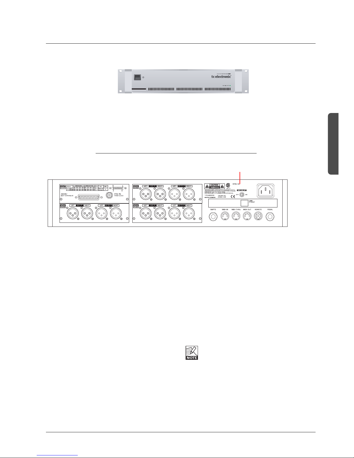
FRONT AND REAR
System 6000 Mainframe Front
Power Key
Switches power On/Off.
PCMCIA slot
For handling of preset banks.
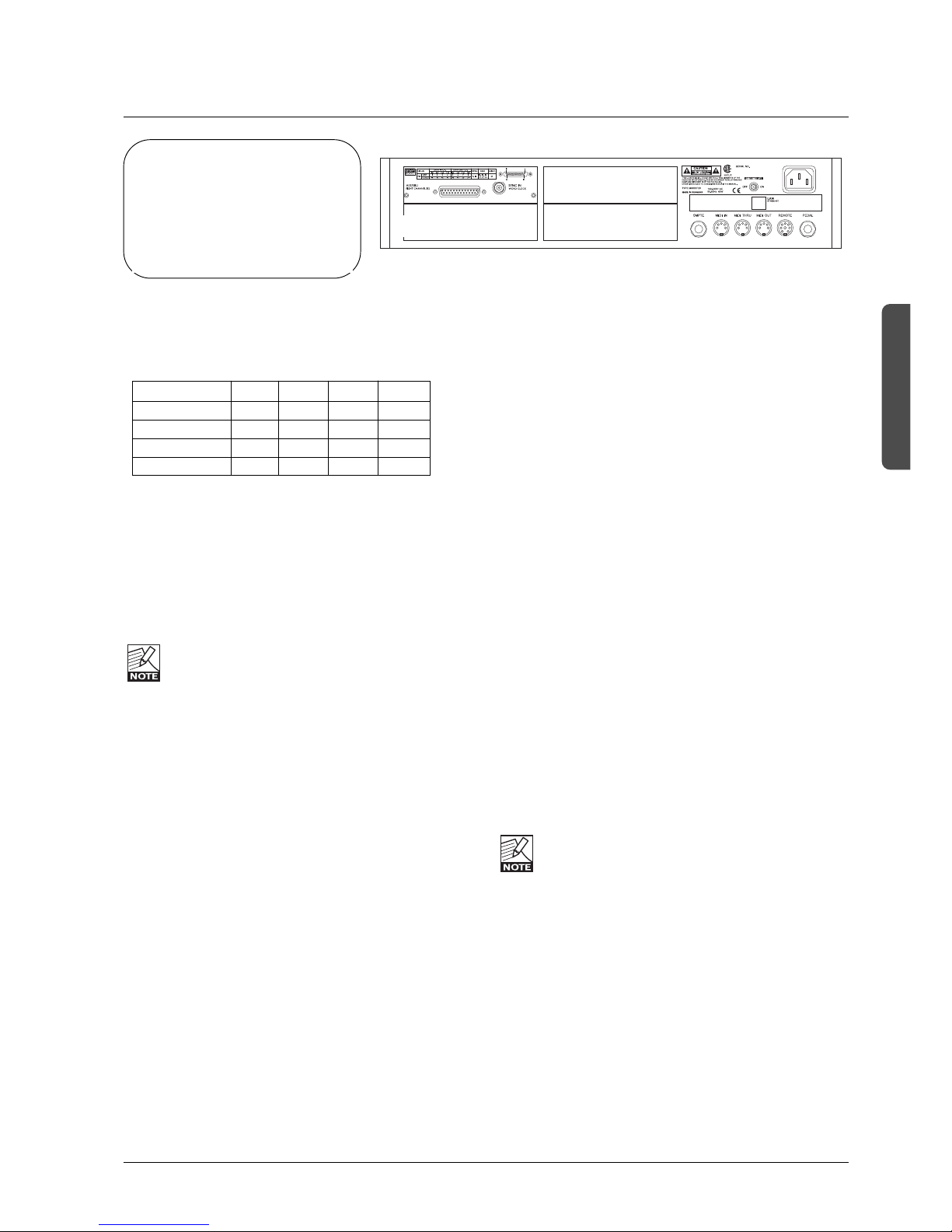
System 6000 Mainframe Rear
I/O Slot - A
I/O Slot - B (AES-8)
DSP Slot
I/O Slot - C
I/O Slots A, B and C
These slots are used for the optional I/O cards ADA 24/96
and AES-8. Slots must be filled consecutively in alphabetic
order.
The System 6000 DSP card fits in the DSP slot only. When
I/O cards are mounted, dip switches on the cards must be
set accordingly. Please see the following page.
An AES-8 card should be installed in “I/O Slot B (AES-8)”
only. If your mainframe rear panel carries a label saying
BUS updated you can install the AES-8 card yourself
following the instructions on the next of this chapter.
DSP Slot
The System 6000 DSP card is placed in the DSP Slot.
Power In
100-230V AC. 50/60Hz - auto-select.
LAN/Ethernet
Connection for external control devices e.g. the TC Icon.
The type is 32 bit PCI Ethernet interface fully compliant
with IEE 802.3u 10/100 Mbps CSMA/CD standards.
The connector type is a 100Base-T RJ-45 (CN13)
SMPTE
1/4” connection for SMPTE sync. Input.
Ground Lift
Use this standard chassis ground lift if you encounter
problems with hum.
MIDI In, Thru and Out
5 pin DIN connectors.
Remote
This connection is for service and test purposes only.
Pedal
General Purpose Input. Connect a TC Master Fader or a
tip to ground switch. Applications vary depending on the
specific algorithm.
Rack-mounting Advice
• The M6000 should not be placed in an environment with
a temperature exceeding 50 degrees celsius.
• Do not cover the ventilation openings on the sides of the
frame.
The cooling fan is activated according to the
temperature inside.
Power On LED
During start-up this LED is red. When the unit is ready for
use, the LED will turn green.
Reset (countersunk)
Press and hold this button during boot to reset the frames
IP address to the default setting: 192.168.1.xx, - where “xx”
is the last two digits in the frames serial number.
Serial Number

8
DSP 6000 - CARD AND CONNECTIONS
Use the supplied cable to connect the AES/EBU
Inputs/Outputs.
Cable type is twisted pair (12 pairs) with common screen.
Recommended impedance: 110ohm.
One end is equipped with an AES/EBU 25 pin DSub
connector, the other end is equipped with four male XLR's
and four female XLR's.
Male XLR's are marked with: Out - 1 to 4.
Female XLR's are marked with: IN- 1 to 4.
Extension cables must be constructed according to
AES/EBU-3 standards.
Following is the pin-out:
Cable pair
Pin number number XLR XLR-pin Assignment
1 1a Female 1 2 Input 1/2 +
2 2a Female 2 2 Input 3/4 +
3 3a Female 3 2 Input 5/6 +
4 4a Female 4 2 Input 7/8 +
5 5a Male 1 2 Output 1/2 +
6 6a Male 2 2 Output 3/4 +
7 7a Male 3 2 Output 5/6 +
8 8a Male 4 2 Output 7/8 +
9 No connection No connection
10 9a Female 1 1 Common
11 No connection No connection
12 9b Female 2 1 Common
13 10a Female 3 1 Common
13 10b Female 4 1 Common
14 1b Female 1 3 Input 1/2 15 2b Female 2 3 Input 3/4 16 3b Female 3 3 Input 5/6 17 4b Female 4 3 Input 7/8 18 5b Male 1 3 Output 1/2 19 6b Male 2 3 Output 3/4 20 7b Male 3 3 Output 5/6 21 8b Male 4 3 Output 7/8 22 11a Male 1 1 Common
23 11b Male 2 1 Common
24 12a Male 3 1 Common
24 12b Male 4 1 Common
25 Shield no connection Common
Note: Twisted cable pairs must be respected
Sync In Word Clock
For connections to external clock via the standard BNC
connector (see illustration above).
When several devices are connected in a chain and
synced via Word Clock, termination on the last device of
the chain is necessary.
As the System 6000 is expected to be the last unit in such
a chain (or the only), the factory default setting on the
System 6000 DSP card is: TERMINATED (75ohm).
If you need to terminate the Word Clock signal elsewhere
in the chain you will need to un-terminate the System 6000
DSP card. To do this you must remove the DSP card from
the mainframe and remove the termination jumper:
• Switch off the power and disconnect main power cord.
• Loosen the two screws holding the DSP card and
remove the card gently.
• Remove the terminating jumper near the BNC plug.
• Insert the card gently in the DSP slot and remount
the screws.
Pins connected via jumper : Terminated (75ohm).
Pins NOT connected via jumper : Not Terminated
Termination jumper
Dip switches 1 to 4 should ALWAYS be set to off.
General Handling
When inserting or removing any modules, avoid touching
the circuit board by handling only the rear panel of the
module. To minimize the static potentials that can cause
damage to the electronic circuits, you should observe
precautionary grounding techniques such as touching a
grounded System 6000 Mainframe immediately before
inserting modules.
BNC
connector
9
HW & INSTALLATION
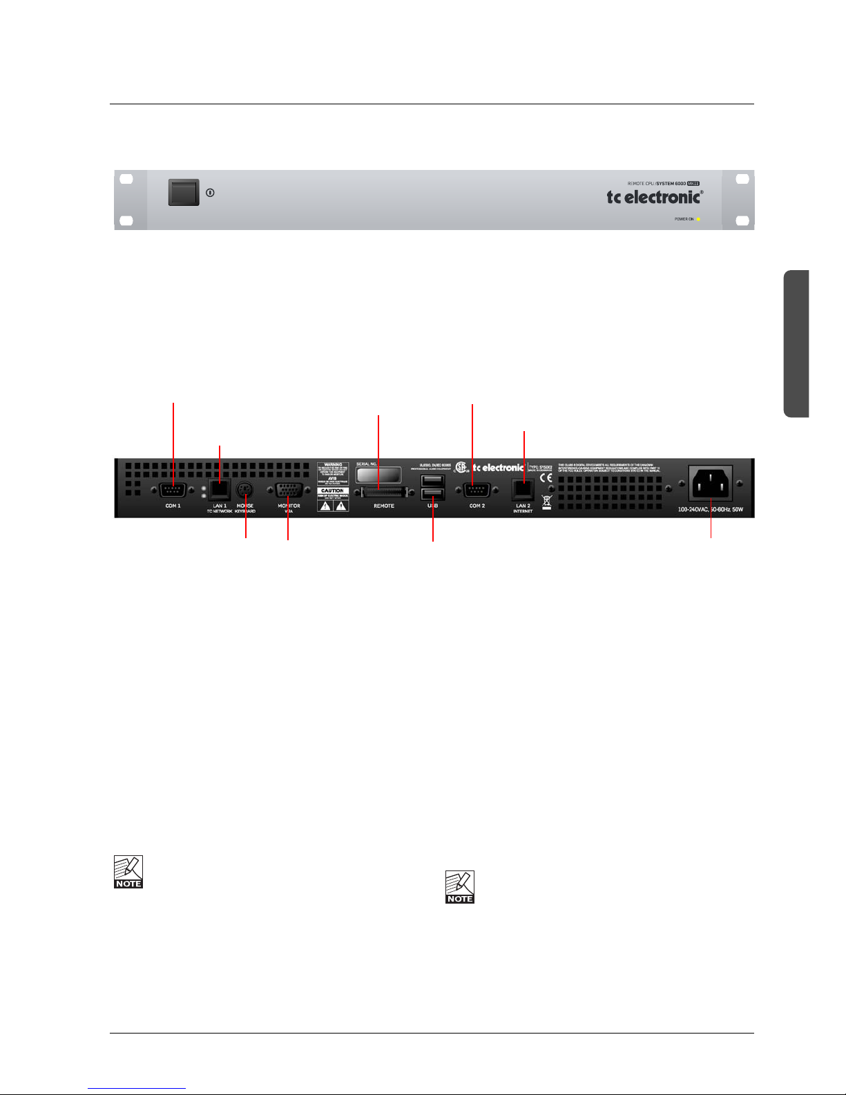
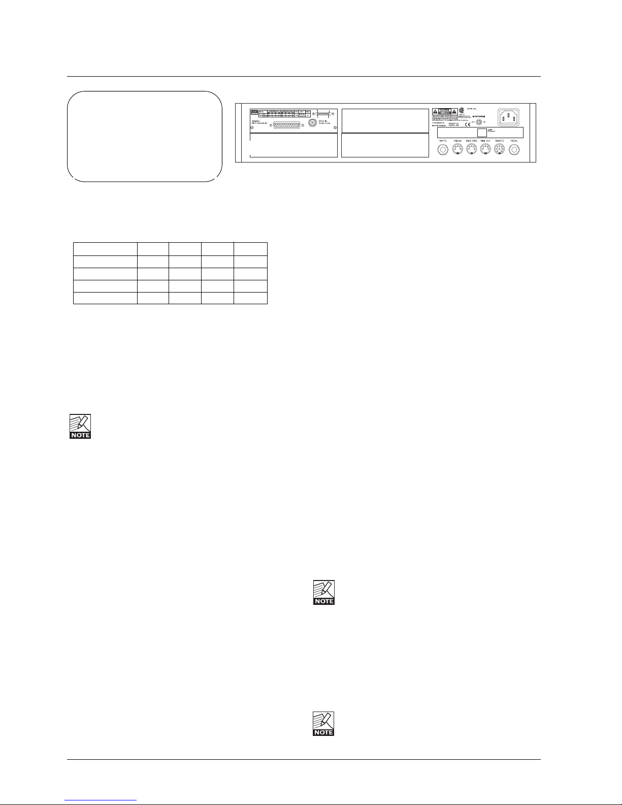
REMOTE CPU
Remote CPU front panel
Remote CPU rear panel
LAN 1
connection for
setups with
multiple frames
COM port 1 COM port 2
PS-2 connection
for PC keyboard
and mouse
Connection
for TC Icon
2 x USB
Type A
Standard
Connectors
Power In
100 - 240V
Connection for
VGA monitor
Power Key
Switches power On/Off. Green LED indicates power on
state.
Ethernet Connection
32 bit PCI Ethernet interface fully compliant with IEE
802.3u 10/100 Mbps CSMA/CD standards.
The connector type is a 100Base-T RJ-45 (CN13)
Connection for PC keyboard or mouse
A standard PS2 Y-splitter must always be used when
connecting a PS2-mouse, a keyboard or both.
This cable is not supplied with the unit.
Connection for TC Icon
36 pin multi-cable connection for TC Icon.
TC Connection Cable.
Use the special TC Icon cable supplied with the
unit ONLY !
USB Connection
USB connection for some TC products with USB
connection. E.g. Reverb4000
Monitor
By connecting a monitor via this standard 15 pin D-Sub
you can have the exact same picture as displayed on the
TC Icon, running in parallel with the Icon. Color depth is 24
bit with a screen resolution of 640 x 480 pixels at 60Hz.
Power
Connect 100-240V AC, 50/60Hz auto-select.
Rack-mounting Advice
• The CPU unit should not be placed in an environment
with a temperature exceeding 50 degrees celsius.
• Do not cover the ventilation openings on the back of the
Remote CPU.
The cooling fan is activated according to the
temperature inside.
Com ports / RS232
For connection of TC units with RS232 interface. E.g. P2
and DB2.
Ethernet/LAN
connection for sw
updates etc.
10
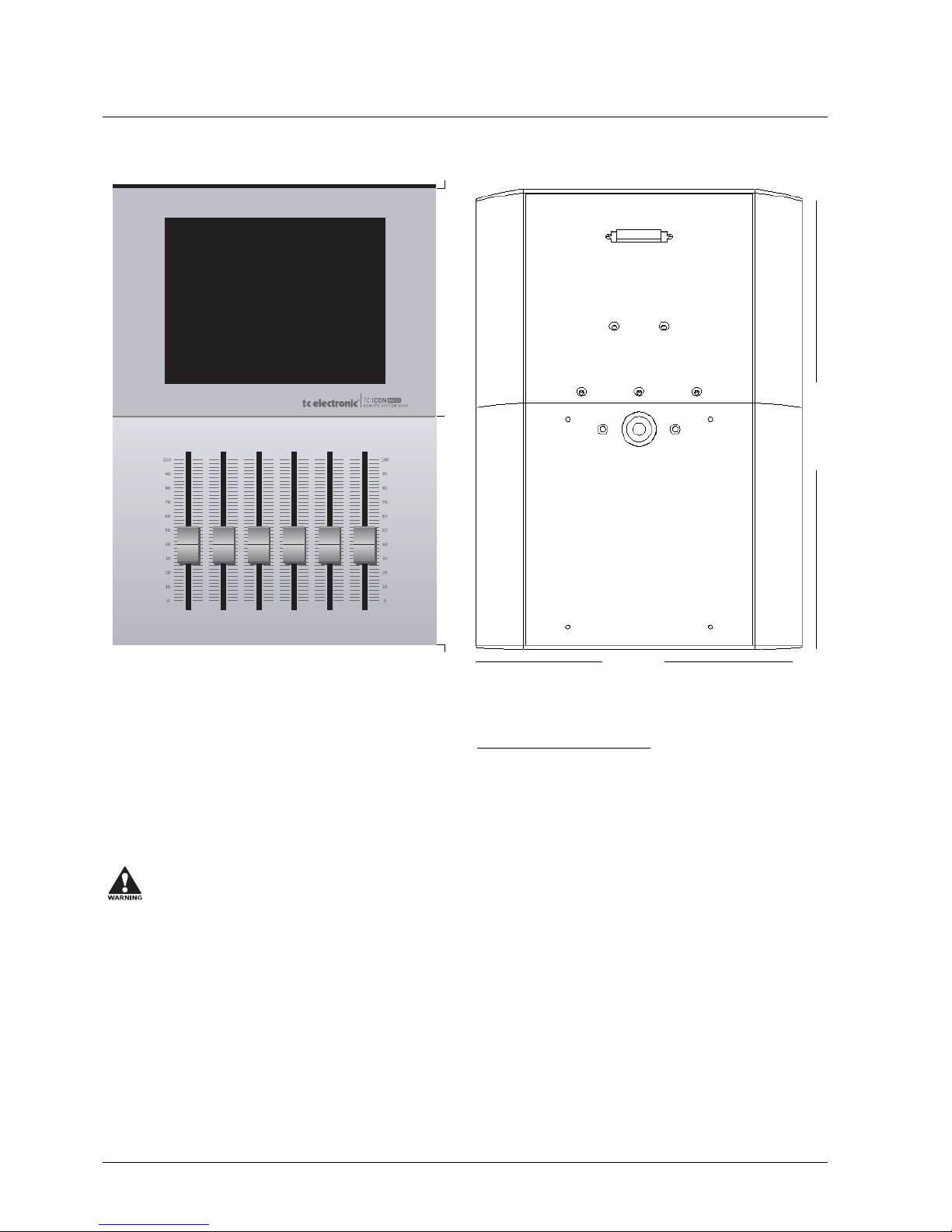
TC ICON
Screen
The TC Icon screen is a touch-sensitive capacitive screen.
The resolution is 640 x 480 16 bit color resolution. The
touch calibration as well as brightness and colors can be
adjusted/selected in the TC Icon Setup menu.
Maintenance
The touch screen must be cleaned only with a soft cloth
slightly moistened with water or a mild detergent solution.
Do not spray liquids directly on the screen.
Faders
The Faders are touch-sensitive. The sensitivity of the
Faders can be adjusted so response to movement is
achieved only when operated with your finger-tips.
This way unintended movement of the Faders with e.g. a
sleeve etc. will not result in changes in parameter values.
The sensitivity can be adjusted in the TC Icon Setup menu.
TC Connection Cable.
Use the special TC Icon cable supplied with the unit ONLY!
No other cables can be used.
The 7.5 meters (22 feet)
cable cannot be extended as this will reduce the power for
the Icon supplied via the cable!
Mic stand mounting
There are two standard threads. 3/8” and 5/8”. The TC Icon
can be mounted on both types without further accessories.
Mounting of plate.
Mount the supplied plate on the rear of the TC Icon, to
assure stable operation when placed on a table or similar.
This is easily done using the 4 screws and screwdriver
supplied with the unit.
Dimensions
D: 279mm
W: 198mm
H front: 33mm
TC Icon Front TC Icon Rear
198 mm
279 mm
11
HW & INSTALLATION
INSTALLING ADDITIONAL I/O CARDS
I/O Cards
I/O cards MUST be mounted in slots A, B and C
consecutively starting in slot A. Dip-switches must be
correctly set on the I/O cards.
To install an ADA 24/96 or AES-8 card in your Main
Frame 6000
1.Switch OFF the unit and disconnect the main
power cord.
2.Remove the DUM-1 option plate(s) or module by
loosening the 2 screws.
3.Insert the card gently and mount the two screws.
ADA 24/96 cards can be mounted in slots A, B or C.
The AES-8 card must be placed in the AES slot.
Static Electricity
As all computer hardware can be sensitive to static
electricity, certain precautions must be taken to protect it
from damage during storage and handling.
Storage
Non-mounted modules should always be stored in
anti-static shielded bags.
General Handling
When inserting or removing any modules, avoid touching
the circuit board by handling only the rear panel of the
module. To minimize the static potentials that can cause
damage to the electronic circuits, you should observe
precautionary grounding techniques such as touching a
grounded System 6000 Mainframe immediately before
inserting modules.
Removing Modules
Before removing any card from your Mainframe, switch off
the power and unplug the main power cable. Unplug all
other connections from the module before unscrewing the
two screws securing the module in the Mainframe. When
removing a module from a Mainframe, the card should be
mounted directly in another Mainframe or placed in an antistatic shielded bag.
Slot A
Slot B / AES-8
Slot C
Dip 1 Dip 2 Dip 3 Dip 4
Slot A on off off off
Slot B on on off off
AES-8 off on off off
Slot C on off on off
Mounting Modules
Before mounting modules in your M6000, switch off the
power and unplug the main power cable. Remove the
dummy-panel or original module from the slot where you
want to install the module. The module should then be
removed from the shielded bag and mounted directly in the
Mainframe by handling the rear panel of the module only.
Avoid touching any components on the PCB-Board.
ADA 24/96 Parameters
To access card specific parameters via the TC Icon:
• Press Frame, System, I/O and Slot A, Slot B or Slot C.
Level In
Changes the analog nominal Input level between +6dBu
and +30dBu in 6dB increments.
The analog Input level enables you to match the System
6000 Mainframe Input to the Output of e.g. your mixer. If
the nominal operating level your mixer is e.g. +4dBu and
you select +12dBu on the Level In parameter you will have
a headroom of 8dB. If you select +16dBu in the Analog In
the headroom will be +12dB, and so forth.
Level Out
Changes the analog Output level between +6dBu and
+24dBu in 6dB increments.
Filter
Select filter type. Chose between - Linear, Natural, Vintage,
Bright and Standard (Std). Further information on these
filters please read the chapter: In Depth Information.
These filters are only available in 44.1 and 48kHz.
Soft Clip
Softclip algorithm running in the 96kHz domain right after
the AD conversion before the down-sampling filter.
Output Connection
Please select the type of connection you are using on the
Output of the card. Select between:
Balanced or unbalanced (with signal on pin 2 or pin 3).
If you are connecting unbalanced cables to the
Outputs when Outmode set to BAL, the Outputs will be
muted due to the short circuit the unbalanced cables cause.
Caution!
The servicing instructions are for use
by qualified personnel only. To
reduce the risk of electric shock do
not perform any servicing other than
that in the operation instructions
unless you are qualified to do so.
12
INSTALLING ADDITIONAL I/O CARDS
I/O Cards
I/O cards MUST be mounted in slots A, B and C
consecutively starting in slot A. Dip-switches must be
correctly set on the I/O cards.
To install an ADA 24/96 or AES-8 card in your Main
Frame 6000
1.Switch OFF the unit and disconnect the main
power cord.
2.Remove the DUM-1 option plate(s) or module by
loosening the 2 screws.
3.Insert the card gently and mount the two screws.
ADA 24/96 cards can be mounted in slots A, B or C.
The AES-8 card must be placed in the AES slot.
Static Electricity
As all computer hardware can be sensitive to static
electricity, certain precautions must be taken to protect it
from damage during storage and handling.
Storage
Non-mounted modules should always be stored in
anti-static shielded bags.
General Handling
When inserting or removing any modules, avoid touching
the circuit board by handling only the rear panel of the
module. To minimize the static potentials that can cause
damage to the electronic circuits, you should observe
precautionary grounding techniques such as touching a
grounded System 6000 Mainframe immediately before
inserting modules.
Removing Modules
Before removing any card from your Mainframe, switch off
the power and unplug the main power cable. Unplug all
other connections from the module before unscrewing the
two screws securing the module in the Mainframe. When
Slot A
Slot B / AES-8
Slot C
Dip 1 Dip 2 Dip 3 Dip 4
Slot A on off off off
Slot B on on off off
AES-8 off on off off
Slot C on off on off
removing a module from a Mainframe, the card should be
mounted directly in another Mainframe or placed in an antistatic shielded bag.
Mounting Modules
Before mounting modules in your M6000, switch off the
power and unplug the main power cable. Remove the
dummy-panel or original module from the slot where you
want to install the module. The module should then be
removed from the shielded bag and mounted directly in the
Mainframe by handling the rear panel of the module only.
Avoid touching any components on the PCB-Board.
ADA 24/96 Parameters
To access card specific parameters via the TC Icon:
• Press Frame, System, I/O and Slot A, Slot B or Slot C.
Level In
Changes the analog nominal Input level between +6dBu
and +30dBu in 6dB increments.
The analog Input level enables you to match the System
6000 Mainframe Input to the Output of e.g. your mixer. If
the nominal operating level your mixer is e.g. +4dBu and
you select +12dBu on the Level In parameter you will have
a headroom of 8dB. If you select +16dBu in the Analog In
the headroom will be +12dB, and so forth.
Level Out
Changes the analog Output level between +6dBu and
+24dBu in 6dB increments.
Filter
Select filter type. Chose between - Linear, Natural, Vintage,
Bright and Standard (Std). Further information on these
filters please read the chapter: In Depth Information.
These filters are only available in 44.1 and 48kHz.
Soft Clip
Softclip algorithm running in the 96kHz domain right after
the AD conversion before the down-sampling filter.
Output Connection
Please select the type of connection you are using on the
Output of the card. Select between:
Balanced or unbalanced (with signal on pin 2 or pin 3).
If you are connecting unbalanced cables to the
Outputs when Outmode set to BAL, the Outputs will
be muted due to the short circuit the unbalanced cables
cause.
Caution!
The servicing instructions are for use
by qualified personnel only. To
reduce the risk of electric shock do
not perform any servicing other than
that in the operation instructions
unless you are qualified to do so.
13
HW & INSTALLATION
SYSTEM 6000 NETWORK & UPDATING SOFTWARE
This section deals with
- basic network terminology related to System 6000
- how to connect System 6000 in a LAN (Local Area
Network)
One MainFrame and one TC Icon Remote
This is the most basic setup with a single Mainframe
connected to a TC Icon Remote CPU via an ethernet
cable. Use the LAN 1 - TC Network connection on the
Remote CPU. This is also known as a “point to point” LAN
(Local Area Network). The cable type to be used for this
setup should be cross-coupled.
If this is your setup, and your system is “fresh out of the
box”, you don’t need to read further. You are all set to go.
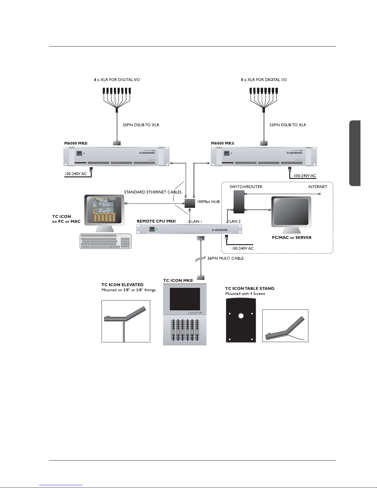
More Mainframes in a setup
As soon as several mainframes are used these should be
connected via a HUB (not supplied). In this scenario
standard ethernet cables (not cross-coupled) must be
used. (please see the illustration System 6000 LAN Setup
Overview in the end of this section). A computer running
the TC Icon software editor can also be hooked up via the hub.
System 6000’s LAN 2 - Internet connection
Unlike its predecessor, TC Icon MKII CPU facilitates a
second LAN connection. As described above LAN 1 is
used for connecting directly to a System 6000 mainframe
or a hub with several frames. LAN 2 - Internet is your link
to a computer or a network of computers with internet
connection. This connection is used for software updates.
The following section explains a few important basic terms
regarding network setups such as TCP/IP and Subnet
Mask. Basic knowledge of these issues is necessary as
soon as your setup consists of more than two items.
Subnet Mask & TCP/IP addresses
The Subnet Mask is a number that defines a group of
computers (or Icons/Mainframes) connected to the network.
All units in the group must have the same Subnet Mask.
The System 6000 Subnet Mask is by default 255.255.255.0
The TCP/IP address is unique to each unit connected in
the network. An IP address consists of 4 numbers
separated by a “.” Example: 192.168.1.1
The first three numbers (e.g. “192.168.1”) must be the
same for each unit, but no two units in the subnet can have
the same the last number.
The TC Icon default address is : 192.168.1.125
The M6000 default address is : 192.168.1.xx
- where “xx” is identical to the last two digits in the
Mainframes serial number. This way multiple S6K frames
can be setup directly out of the box without changing the IP
numbers.
If your computer’s IP address (or any in the network) is one
of the above you have two options. Either to alter the three
last number in your computer’s IP address or to alter the
last number in the TC Icon and Mainframe IP addresses.
Setting Subnet Mask & TCP/IP on System 6000
The System 6000 Subnet Mask and I/P address can be set
via the TC Icon page: frame/system/main/net
The frames IP address can at all times be reset to default:
192.168.1.xx*, by pressing and holding the reset button on
the frontpanel during boot-up.
* “xx” is the last two digits in the serial number as
previously mentioned.
Note that there is a small risk that two frames have
the same last 2 digits in the serial number and thus
will conflict after a reset. Solution: - reset one frame
and change its IP address before connecting the
second.
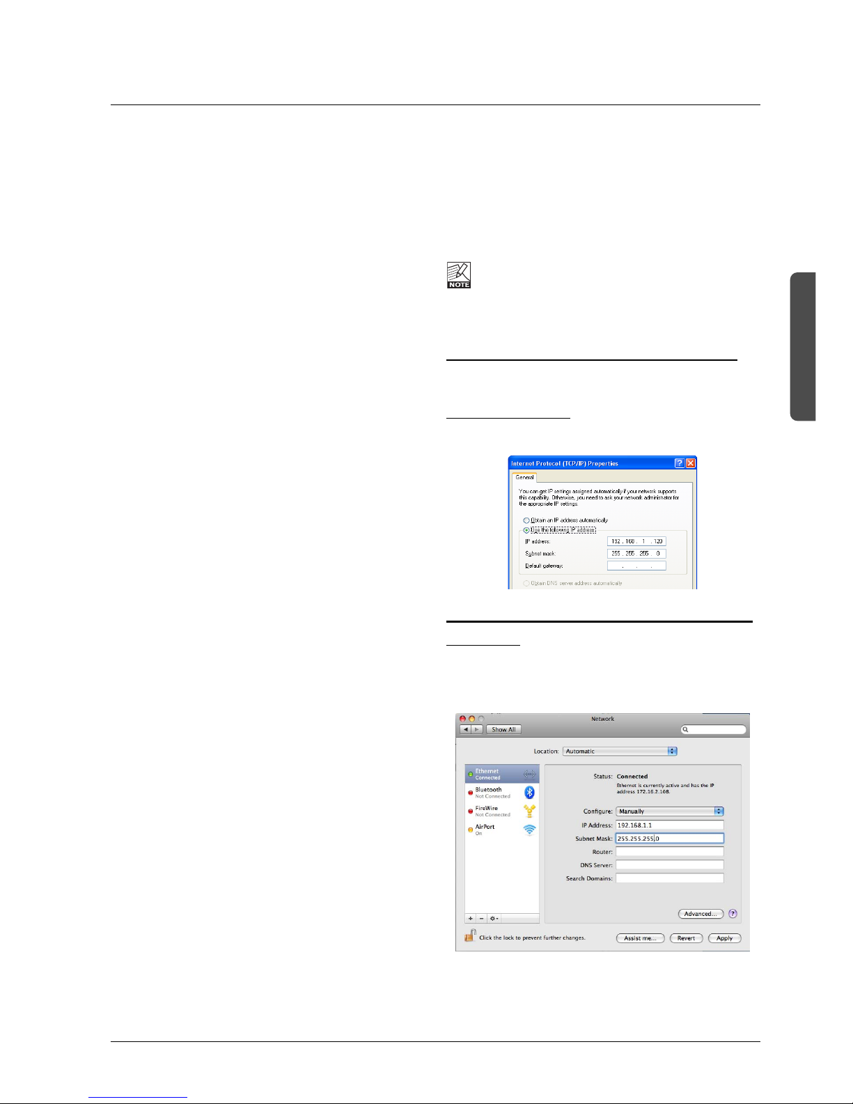
Setting Subnet Mask & TCP/IP on a PC
To find the TCP/IP address and the Subnet Mask settings
on your computer running Windows:
Example - Windows XP
Go to Control Panel, Network Connections, Internet
Protocol (TCP/IP).
Subnet Mask & TCP/IP address on a Mac
Example OSX
• Go to “System Preferences - Network.
• Under Configure select “manually”.
• Set TCP/IP address.
14
Step 2 - Mac & PC
• The three software types are now be visible when you
press the panes: Frames, DSP and NET.
The Icon editor shows the update status via a progress bar.
• Update the software in the following order:
- Frame
- NET
- DSP
A log file of the update can be obtained for service
purposes. The file is saved at the location where the
software is uploaded from. The file lists the result of the
operation and can be opened with most text editors.
The file is saved in the same folder as the software is
placed and read/write access for that folder must be set.
To verify correct update-procedure has taken
place, - check the software version numbers both
before
and after an update. These version numbers
are located on the Frame/System/Main/Net page.
SYSTEM 6000 NETWORK & UPDATING SOFTWARE
Updating Software
System 6000 is a constantly evolving platform and updating
software is a standard procedure to keep the system up-todate. Upgrading is easily done following the procedures
below.
This first section deals with updating software for the
Mainframe - NOT the hardware version of the TC Icon
MKII. To learn about updating the software for the
hardware Icon please see the section “Updating TC Icon
Software”.
Updating Mainframe 6000 software
There are three types of software in a System 6000
mainframe.
• Frame software
• Net (Ethernet) software
• DSP software
There is also software for the AES-8 card. This software is
rarely updated and should only
be upgraded if a newer
AES-8 software version than the one you are currently
using, is available. Please follow the update instructions
provided with the downloaded AES-8 software.
Acquiring the latest software
Latest software can be downloaded via
www.tcelectronic.com or directly via the pages:
http://www.tcelectronic.com/reverb6000software.asp
http://www.tcelectronic.com/software mastering6000.asp
- depending on your model.
• Install the TC Icon Editor on you PC or Mac if you
haven't done so already (see the section: TC Icon Editor
Installation on the following pages)
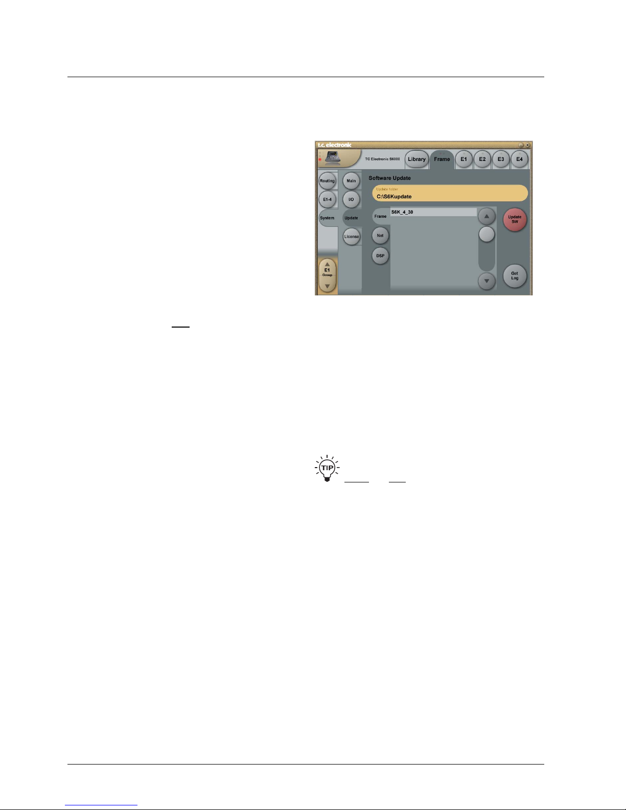
Step 1
PC
• Create a folder called “S6Kupdate” in the root directory
on your “c” drive. The folder path is then - c:\S6Kupdate
• Copy the latest Frame, DSP and Ethernet software files
to this folder
• In the TC Icon editor go to the Frame-System-Update
page and enter the path “C:\S6Kupdate” as the Update
folder path
- go to Step 2
MAC
• Create a folder under “Home” called “S6Kupdate”
The path for that folder is then - /Users/xx/S6Kupdate
(xx - is the username)
• Copy the latest Frame, DSP and Ethernet sw files to this
folder.
• In the TC Icon editor go to the Frame-System-Update
page and enter the path “/Users/xx/S6Kupdate” as the
Update folder path
- go to Step 2
15
HW & INSTALLATION
SYSTEM 6000 NETWORK & UPDATING SOFTWARE
Updating TC Icon Software
Beware, the 19 “Remote CPU rack module and the TC
Icon are viewed as one inseparable unit and therefore
there is only one TC Icon software-package.
• Make sure your System 6000 is connected to the Internet
via the LAN2 Internet connection. Status on the
connection can be seen on the Setup/net page.
It should say “Connected to TC”
• Update the TC Icon software directly by pressing Update
from TC Website
The update procedure directly from web as described
above is the easiest way to update your TC Icon software.
However, if your System 6000 is not connected to the web
you can also update the TC Icon software from a shared
folder on a PC or MAC.
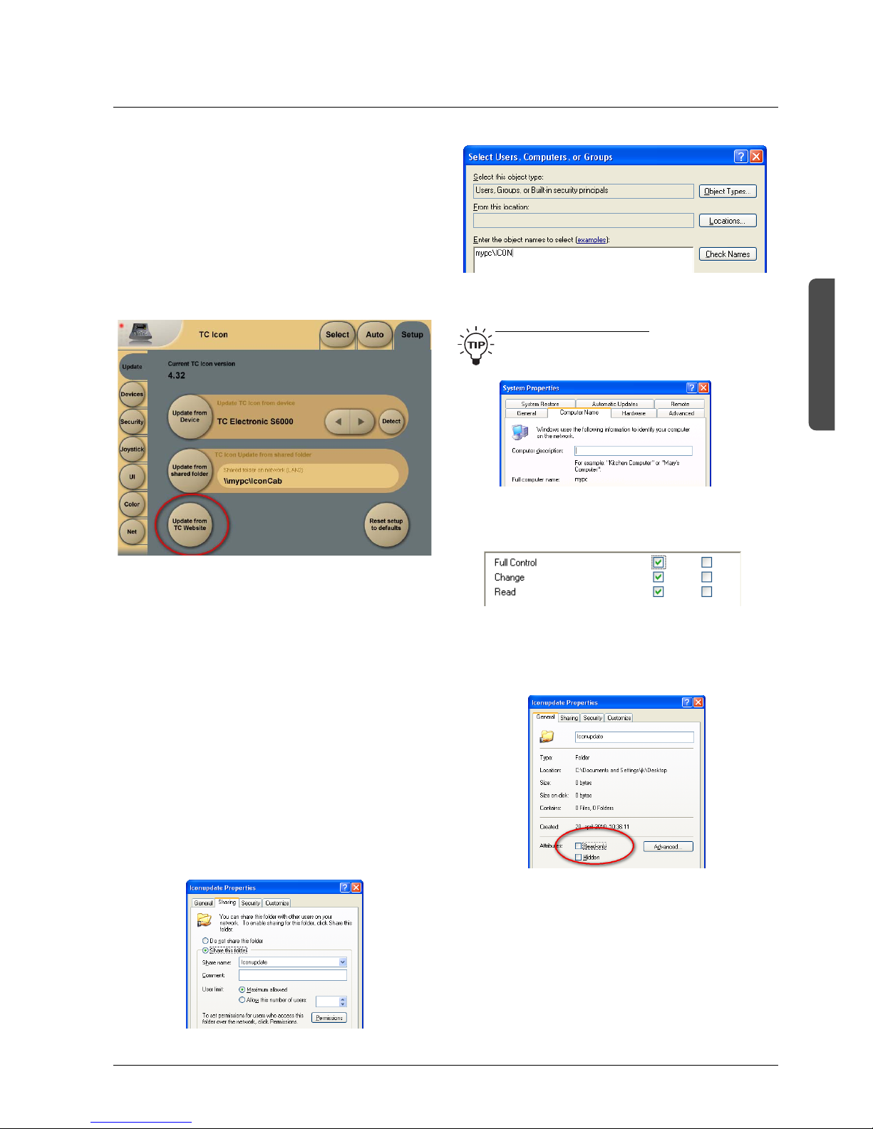
Updating TC Icon software from a shared folder on a PC
• Connect the LAN2 connection to your computers network
connection. For a direct connection use a cross-coupled
ethernet cable. If connected via a hub, use standard
(non-cross-coupled) cables.
• Download and unzip the TC Icon cab file and place the
file in a folder. This folder needs to be shared:
• Right-click on the folder and select properties
• Select Sharing
• Mark “Share this folder”
• Type in the name ”iconupdate” as share name
• Mark “Maximum allowed” in User Limit.
• Then press “Permissions” and press “Add”
Notice that “mypc” - is the name of the computer.
T
o find the computers name:
Press, START and right-click on My Computer and
select properties. Select the tab “Computer Name”:
• Press “Check Names” to verify
• Check: Full Control, Change and Read.
• On the “General” page make sure that “Read only” is
NOT marked. This allows the update software to write a
Result file describing the update process.
• Press Apply and OK
• The path to the folder is now \\mypc\iconupdate and it
is available on the network. “xxxx” is the name of the
computer.
16
SYSTEM 6000 NETWORK & UPDATING SOFTWARE
TC Icon Editor Installation
The TC Icon Software Editor for PC and Mac is a fully
operational software version of the TC Icon Remote for the
System 6000. The software is free to download via
www.tcelectronic.com
Installation - PC
System Requirement
s
• Windows 2000, NT, XP, Vista or 7
• 1 GB RAM
• INTEL/AMD 1.66GHz
Updating/inst
alling the TC Icon Software Editor
• Go to:
http://www.tcelectronic.com/reverb6000software.asp - or
http://www.tcelectronic.com/mastering6000software.asp
• Download TC Icon Editor for Windows
• Open the zip-file
• Open the cab-file
• Copy the Icon file to your desktop (or another location)
Installation - Mac
System Requirement
s
• OSX 10.4, 10.5, 10.6
• Power PC or Intel Mac
• Stuffit Expander installed
Updating/inst
alling the TC Icon Software Editor
• Go to:
http://www.tcelectronic.com/reverb6000software.asp - or
http://www.tcelectronic.com/mastering6000software.asp
• Download Icon Editor for Mac
• Open the Icon.dmg file placed on your desktop and drag
the application to your desktop or another location of
your choice
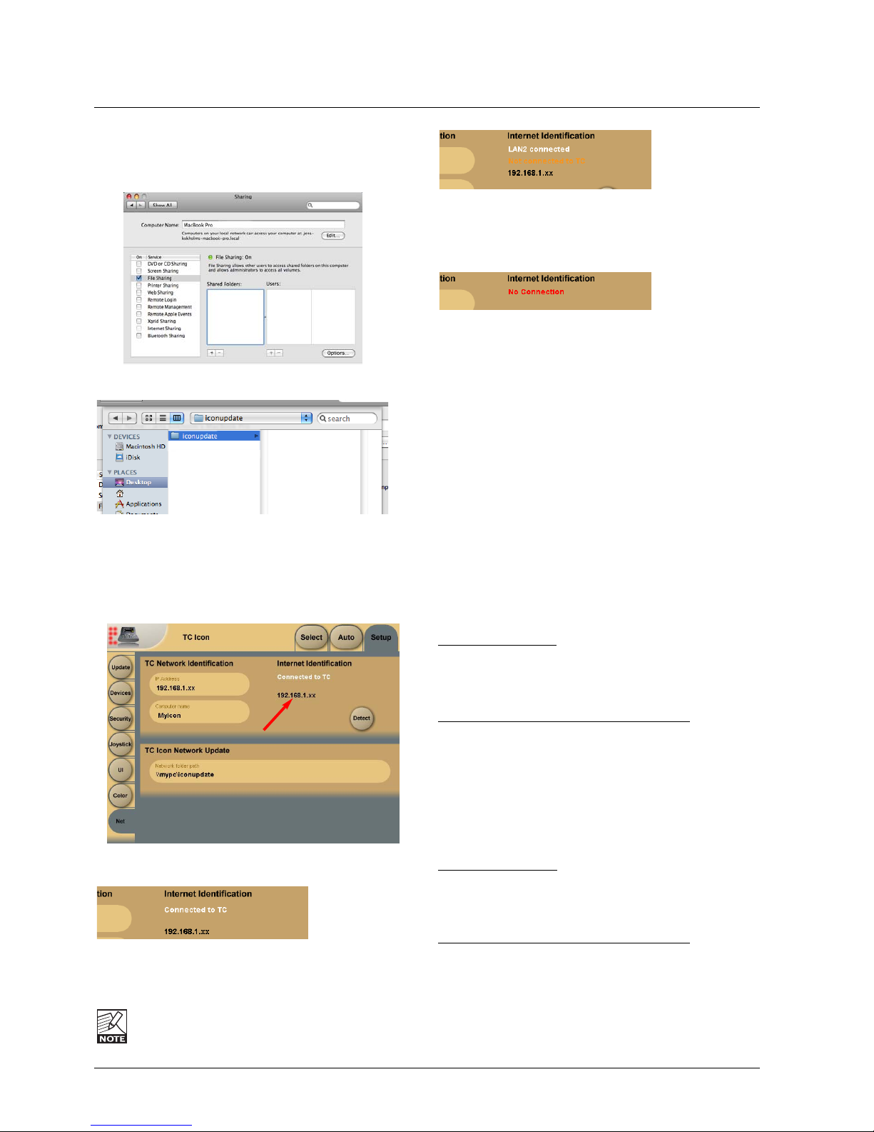
Updating TC Icon software from a shared folder on a MAC
On Mac computers shared folders are setup in System
Preferences - Shared.
Press “+” under Shared Folders
• Select the folder holding the software and press “Add”.
• The folder is now shared.
Internet Identification
- Setup/Net page
Three indications can be given:
- this indicates that LAN2 is correctly connected to TC
Electronics download server. Go to the Update page and
press “Update From TC Website”.
TC Electronic does NOT have access to any files or
information on devices connected to LAN2.
- “Not connected to TC”, - indicates that LAN2 is correctly
connected to the internet but you are either on a closed
network with no internet access, or the download server at
TC Electronic cannot be reached.
- you are not connected to the internet. Please check
network setup and all cables, - then try again.
17
HW & INSTALLATION
Hubs
For optimal performance use a 100Mbit Hub.
We recommend Hubs from 3Com and Cisco.
Warning
This product includes an “Ethernet Port” which allows this
product to be connected to a local area network (LAN).
Only connect to networks that remain inside the building.
Do not connect to networks that go outside the building.
SYSTEM 6000 NETWORK & UPDATING SOFTWARE
18
Engine Structure
The core element of Mainframe 6000 is the 4 Engine
structure. This structure enables you to run up to four
powerful algorithms/presets simultaneously. Each Engine is
capable of utilizing up to 8 Inputs and 8 Outputs, depending
on the selected algorithm/preset. Up to 16 physical Input
and 16 physical Output channels can be routed in the most
flexible way.
Engine Resources
The Mainframe 6000 offers a large amount of real-time
DSP-resources. The flexible DSP distribution structure lets
you run up to 4 Engine presets at the same time using any
available algorithms. How about running your signal from a
full-blown VSS-5.1 Reverb through a MD-5.1 Multiband
Dynamics algorithm to a Toolbox-5.1 for e.g format
conversion and total control of levels? Setups like these
are no problem with the System 6000.
Be aware that when using some of the most powerful
algorithms or running at 96kHz, less than 4 Engine presets
can be loaded simultaneously. Required Engine resources
pr. algorithm is listed for each algorithm in the algorithmchapter.
Introduction
This section of the manual is a general introduction on how
to operate System 6000 via the TC Icon. The basic System
6000 consists of a Mainframe with a DSP card and up to
three I/O cards, plus a TC Icon remote with Remote CPU.
Several mainframes as well as several TC Icons can be
hooked up at the same time via a standard Local Area
Network (LAN).
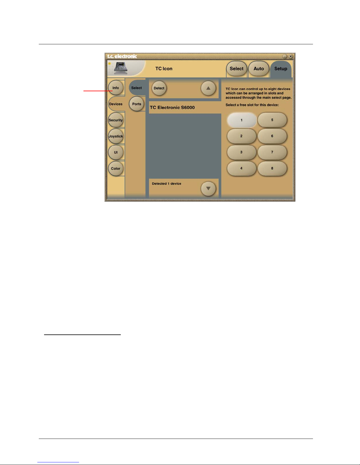
Accessing a Mainframe
First time you connect the Mainframe and TC Icon you
must:
• Power up all devices.
• The TC Icon Setup page appears (see above).
• On the Setup-Devices-Select page you press “DETECT”
and then assign the detected mainframes to the 8
locations as you prefer.
Assigning Frames to shortcut keys
- un-assign by pressing one of the eight shortcut keys
- select the Frame you wish to assign from the list of
connected units,
- then press the shortcut key you wish to assign to
• Go to the Select page (top-tab), and press the large
Mainframe key of the connected frame you wish to
access (see Fig 2).
• TC Icon now retrieves data from the Mainframe.
• When ready you will see the Frame - Routing
display, and you are ready to operate the
Mainframe.
To go back to the TC Icon pages press the Icon logo in the
top left corner.
List of connected
units
BASIC OPERATION
 Loading...