

Page 1

OPERATOR’S
MANUAL
Model C606
Combination Freezer
Original Operating Instructions
059714-M
May, 2004 (Original Publication )
(Updated 8/5/2020)
Page 2

Complete this page for quick reference when service is required:
Taylor Distributor: __________________________________________________________
Address:_________________________________________________________________
Phone: __________________________________________________________________
Service: _________________________________________________________________
Parts: ___________________________________________________________________
Date of Installation: ________________________________________________________
Information found on the data label:
Model Number:____________________________________________________________
Serial Number: ____________________________________________________________
Electrical Specs: Voltage__________________ Cycle__________
Phase__________________________________
Maximum Fuse Size: ______________________________________________________ A
Minimum Wire Ampacity: ___________________________________________________A
Note: Continuing research results in steady improvements; therefore, information in this manual is subject to change
without notice.
Note: Only instructions originating from the factory or its authorized transla tion repr esentative(s) are considered to be
the original set of instructions.
© 2004 Taylor Company
(Updated 8/5/2020)
059714-M
Any unauthorized reproduction, disclosure, or distribution of copies by any person of any portio n of this wor k may be
a violation of copyright law of the United States of America and other countries, could result in the awarding of
statutory damages of up to $250,000 (17 USC 504) for infringement, and may result in further civil and criminal
penalties. All rights rese rved.
Taylor Company
750 N. Blackhawk Blvd.
Rockton, IL 61072
Page 3

Section 1: To the Installer
Installer Safety . . . . . . . . . . . . . . . . . . . . . . . . . . . . . . . . . . . . . . . . . . . . . . . . . . . . . . .1-1
Site Preparation . . . . . . . . . . . . . . . . . . . . . . . . . . . . . . . . . . . . . . . . . . . . . . . . . . . . . .1-1
Air-Cooled Machines. . . . . . . . . . . . . . . . . . . . . . . . . . . . . . . . . . . . . . . . . . . . . . . . . . .1-1
Water Connections . . . . . . . . . . . . . . . . . . . . . . . . . . . . . . . . . . . . . . . . . . . . . . . . . . . .1-2
Electrical Connections. . . . . . . . . . . . . . . . . . . . . . . . . . . . . . . . . . . . . . . . . . . . . . . . . .1-2
Beater Rotation. . . . . . . . . . . . . . . . . . . . . . . . . . . . . . . . . . . . . . . . . . . . . . . . . . . . . . .1-3
Refrigerant . . . . . . . . . . . . . . . . . . . . . . . . . . . . . . . . . . . . . . . . . . . . . . . . . . . . . . . . . .1-4
Section 2: To the Operator
Section 3: Safety
Section 4: Operator Parts Identification
Exploded View . . . . . . . . . . . . . . . . . . . . . . . . . . . . . . . . . . . . . . . . . . . . . . . . . . . . . . .4-1
Front View. . . . . . . . . . . . . . . . . . . . . . . . . . . . . . . . . . . . . . . . . . . . . . . . . . . . . . . . . . .4-3
Syrup Cabinet View. . . . . . . . . . . . . . . . . . . . . . . . . . . . . . . . . . . . . . . . . . . . . . . . . . . .4-5
Syrup Pump and Tubes . . . . . . . . . . . . . . . . . . . . . . . . . . . . . . . . . . . . . . . . . . . . . . . .4-6
X57028-XX Pump A.—Mix Simplified - Shake . . . . . . . . . . . . . . . . . . . . . . . . . . . . . . .4-7
X57029-XX Pump A.—Mix Simplified - Soft Serve. . . . . . . . . . . . . . . . . . . . . . . . . . . .4-8
X59304 Syrup Line Assembly—Thin Viscosity Syrup. . . . . . . . . . . . . . . . . . . . . . . . . .4-9
X56652 Syrup Line Assembly—Thick Viscosity Shake Syrup (Optional). . . . . . . . . .4-10
X58450 Syrup Line Assembly—Syrup-in-Bag Option. . . . . . . . . . . . . . . . . . . . . . . . .4-11
Mix Hopper—Top View. . . . . . . . . . . . . . . . . . . . . . . . . . . . . . . . . . . . . . . . . . . . . . . .4-12
Accessories. . . . . . . . . . . . . . . . . . . . . . . . . . . . . . . . . . . . . . . . . . . . . . . . . . . . . . . . .4-13
X44127 Brush Kit Assembly . . . . . . . . . . . . . . . . . . . . . . . . . . . . . . . . . . . . . . . . . . . .4-15
X53800-BRN/TAN Syrup Pump . . . . . . . . . . . . . . . . . . . . . . . . . . . . . . . . . . . . . . . . .4-16
Beater Door Assembly—Shake Side . . . . . . . . . . . . . . . . . . . . . . . . . . . . . . . . . . . . .4-17
Beater Door Assembly—Soft Serve Side . . . . . . . . . . . . . . . . . . . . . . . . . . . . . . . . . .4-19
059088 Parts Tray—Shake Side. . . . . . . . . . . . . . . . . . . . . . . . . . . . . . . . . . . . . . . . .4-20
059087 Parts Tray—Soft Serve Side . . . . . . . . . . . . . . . . . . . . . . . . . . . . . . . . . . . . .4-21
056525 Parts Tray—Simplified Pump. . . . . . . . . . . . . . . . . . . . . . . . . . . . . . . . . . . . .4-22
Table of Contents
Section 5: User Interface
Symbol Definitions . . . . . . . . . . . . . . . . . . . . . . . . . . . . . . . . . . . . . . . . . . . . . . . . . . . .5-2
Power Switch . . . . . . . . . . . . . . . . . . . . . . . . . . . . . . . . . . . . . . . . . . . . . . . . . . . . . . . .5-2
Vacuum Fluorescent Display . . . . . . . . . . . . . . . . . . . . . . . . . . . . . . . . . . . . . . . . . . . .5-2
Indicator Lights . . . . . . . . . . . . . . . . . . . . . . . . . . . . . . . . . . . . . . . . . . . . . . . . . . . . . . .5-2
Heat Cycle Key . . . . . . . . . . . . . . . . . . . . . . . . . . . . . . . . . . . . . . . . . . . . . . . . . . . . . . .5-2
Reset Mechanism . . . . . . . . . . . . . . . . . . . . . . . . . . . . . . . . . . . . . . . . . . . . . . . . . . . . .5-3
Air/Mix Pump Reset Mechanism. . . . . . . . . . . . . . . . . . . . . . . . . . . . . . . . . . . . . . . . . .5-3
Adjustable Draw Handle . . . . . . . . . . . . . . . . . . . . . . . . . . . . . . . . . . . . . . . . . . . . . . . .5-3
Model C606 i
Page 4

Table of Contents
Shake Fill Level Adjustment . . . . . . . . . . . . . . . . . . . . . . . . . . . . . . . . . . . . . . . . . . . . . 5-3
VFD Screens . . . . . . . . . . . . . . . . . . . . . . . . . . . . . . . . . . . . . . . . . . . . . . . . . . . . . . . . 5-4
Manager's Menu. . . . . . . . . . . . . . . . . . . . . . . . . . . . . . . . . . . . . . . . . . . . . . . . . . . . . . 5-7
Section 6: Operating Procedures
Machine Setup . . . . . . . . . . . . . . . . . . . . . . . . . . . . . . . . . . . . . . . . . . . . . . . . . . . . . . . 6-1
Sanitizing—Shake Side . . . . . . . . . . . . . . . . . . . . . . . . . . . . . . . . . . . . . . . . . . . . . . . 6-11
Sanitizing—Soft Serve Side . . . . . . . . . . . . . . . . . . . . . . . . . . . . . . . . . . . . . . . . . . . . 6-13
Priming—Shake Side . . . . . . . . . . . . . . . . . . . . . . . . . . . . . . . . . . . . . . . . . . . . . . . . . 6-14
Priming—Soft Serve Side. . . . . . . . . . . . . . . . . . . . . . . . . . . . . . . . . . . . . . . . . . . . . . 6-15
Daily Closing Procedures . . . . . . . . . . . . . . . . . . . . . . . . . . . . . . . . . . . . . . . . . . . . . . 6-15
Daily Opening Procedures . . . . . . . . . . . . . . . . . . . . . . . . . . . . . . . . . . . . . . . . . . . . . 6-20
Syrup System . . . . . . . . . . . . . . . . . . . . . . . . . . . . . . . . . . . . . . . . . . . . . . . . . . . . . . . 6-25
Syrup Topping Pump . . . . . . . . . . . . . . . . . . . . . . . . . . . . . . . . . . . . . . . . . . . . . . . . . 6-27
Manual Brush Cleaning . . . . . . . . . . . . . . . . . . . . . . . . . . . . . . . . . . . . . . . . . . . . . . . 6-32
Draining Product from the Freezing Cylinder . . . . . . . . . . . . . . . . . . . . . . . . . . . . . . . 6-32
Rinsing . . . . . . . . . . . . . . . . . . . . . . . . . . . . . . . . . . . . . . . . . . . . . . . . . . . . . . . . . . . . 6-33
Cleaning and Sanitizing . . . . . . . . . . . . . . . . . . . . . . . . . . . . . . . . . . . . . . . . . . . . . . . 6-34
Disassembly—Shake Side . . . . . . . . . . . . . . . . . . . . . . . . . . . . . . . . . . . . . . . . . . . . . 6-34
Disassembly—Soft Serve Side. . . . . . . . . . . . . . . . . . . . . . . . . . . . . . . . . . . . . . . . . . 6-35
Brush Cleaning. . . . . . . . . . . . . . . . . . . . . . . . . . . . . . . . . . . . . . . . . . . . . . . . . . . . . . 6-36
Syrup System—Scheduled Maintenance. . . . . . . . . . . . . . . . . . . . . . . . . . . . . . . . . . 6-37
Section 7: Operator Checklist
During Cleaning and Sanitizing . . . . . . . . . . . . . . . . . . . . . . . . . . . . . . . . . . . . . . . . . . 7-1
Troubleshooting Bacterial Count . . . . . . . . . . . . . . . . . . . . . . . . . . . . . . . . . . . . . . . . . 7-1
Regular Maintenance Checks. . . . . . . . . . . . . . . . . . . . . . . . . . . . . . . . . . . . . . . . . . . . 7-1
Winter Storage . . . . . . . . . . . . . . . . . . . . . . . . . . . . . . . . . . . . . . . . . . . . . . . . . . . . . . . 7-2
Section 8: Troubleshooting Guide
Section 9: Parts Replacement Schedule
Section 10: Limited Warranty
Section 11: Limited Warranty on Parts
ii Model C606
Page 5
Section 1
To the Installer
The following information has been included in the
manual as safety and regulatory guidelines. For complete
installation instructions, please see the Installation
Checklist.
Installer Safety
IMPORTANT! In all areas of the world,
machines should be installed in accordance with existing
local codes. Please contact your local authorities if you
have any questions.
Care should be taken to ensure that all basic safety
practices are followed during the installation and
servicing activities related to the installation and service
of Taylor
®
machines.
• Only Taylor service personnel should perform
installation, maintenance, and repairs on Taylor
machines.
• Authorized service personnel should consult
OSHA Standard 29CFRI910.147 or the
applicable code of the local area for the industry
standards on lockout/tagout proced u re s bef or e
beginning any installation or repairs.
• Authorized service personnel must en su re tha t
the proper personal protective equipment (PPE)
is available and worn when required during
installation and service.
• Authorized service personnel must remove all
metal jewelry, rings, and watches before
working on electrical equipment.
All repairs must be performed by an authorized Taylor
service technician.
Site Preparation
Inspect the area where the machine will be installed
before uncrating it. Make sure that all possible ha zards to
the user and the machine have been addressed.
WARNING! Only install this machine in a
location where its use and maintenance is restric te d to
trained personnel. Failure to comply may result in
personal injury.
Air-Cooled Machines
Do not obstruct air intake and discharge openings.
Air-cooled machines require a min imum of 3 in. ( 76 mm)
of clearance around all sides to allow for adequate air
flow across the condensers. Install the deflector provided
to prevent recirculation of warm air. Failure to allow
adequate clearance can reduce the refrigeration capacity
and may cause permanent damage to the compressors.
For Indoor Use Only: This machine is designed to
operate indoors under normal ambient tempera tures of
70°F to
successfully performed in high ambient temperatures of
104°C (40°C) at reduced capacities.
75°F (21°C to 24°C). The freezer has
1
DANGER! The main power supply(s) to the
machine must be disconnected prior to performing any
installation, maintenance, or repairs. Failure to follow this
instruction may result in personal injury or death from
electrical shock or hazardous moving parts, as well as
poor performance or damage to the machine.
WARNING! This machine has many sharp
edges that can cause severe injuries.
To the Installer
Model C606
1-1
Page 6
TO THE INSTALLER
FOLLOW YOUR LOCAL ELECTRICAL CODES.
Water Connections
(Water-Cooled Machines Only)
An adequate cold water supply must be provided with a
hand shutoff valve. On the underside rear of the base
pan, two 3/8 in. Iron Pipe Size (IPS) water connections
for inlet and outlet have been provided for easy hookup.
Permanently connect the machine using 1/2 in. (12.7
1
mm) inside diameter water lines. (Flexible lines are
recommended, if local codes permit.) Depending on local
water conditions, it may be advisable to install a water
strainer to prevent foreign substances from clogging the
automatic water valve. There will be only one water in
and one water out connection. Do not install a hand
shutoff valve on the water out line! Water should always
flow in this order: first, through the automatic water valve;
second, through the condenser; and third, through the
outlet fitting to an open trap drain.
IMPORTANT! A backflo w preventio n device is
required on the incoming water connection side. Please
see the applicable national, state, and local codes for
determining the proper configuration. Water pressure to
the unit must not exceed 150 psi (1034 kPa).
WARNING! This machine must NOT be
installed in an area where a water jet or hose can be
used. NEVER use a water jet or hose to rinse or clean
the machine. Failure to follow this instruction may result
in electrocution.
Electrical Connections
In the United States, this machine is intended to be
installed in accordance with the National Electrical Code
(NEC), ANSI/NFPA 70-1987. The purpose of the NEC
code is the practical safeguarding of persons and
property from hazards arising from the use of electricity.
This code contains provisions considered necessary for
safety. In all other areas of the world, machine should be
installed in accordance with the existing local codes.
Please contact your local authorities.
Each machine requires one power supply for each data
label on the machine. Check the data label(s) on the
freezer for branch circuit overcurrent protection or fuse,
circuit ampacity, and other electrical specifications. See
the wiring diagram provided inside the electrical box for
proper power connections.
IMPORTANT! An equipotential grounding lug is
provided with this machine. Some countries require the
grounding lug to be properly attached to the rear of the
frame by the authorized installer . The installation location
is marked by the equipotential bonding symbol (5021 of
IEC 60417-1) on both the removable panel and the
machine's frame.
WARNING! This machine must be properly
grounded. Failure to do so can result in severe personal
injury from electrical shock.
CAUTION! This machine must be installed on
a level surface to avoid the hazard of tipping. Extreme
care should be taken in moving this machine for any
reason. Two or more persons are required to safely move
this machine. Failure to comply may result in personal
injury or damage to the machine.
The authorized installer should inspect the machine for
damage and promptly report any damage to the local
authorized Taylor distributor .
This machine is made using USA hardware sizes. All
metric conversions are approximate.
1-2
Model C606
WARNING! Avoid injury .
• DO NOT operate the machine unless it is
properly grounded.
• DO NOT operate the machine with larger fuses
than specified on the machine's data label.
• All repairs should be performed by an
authorized Taylor service technician.
• The main power supplies to the machine must
be disconnected prior to performing installation,
repairs, or maintenance.
To the Installer
Page 7
TO THE INSTALLER
• For Cord-Connected Machines: Only
authorized Taylor service technicians or
licensed electricians may install a plug or
replacement cord on the machine.
• Machines that are permanently connected to
fixed wiring and for which leakage currents may
exceed 10 mA, particularly when disconnected
or not used for long periods, or during initial
installation, shall have protective devices to
protect against the leakage of current, such as a
GFI, installed by the authorized personnel to the
local codes.
• Stationary machines which are not equipped
with a power cord and a plug or another device
to disconnect the appliance from the power
source must have an all-pole disconnecting
device with a contact gap of at least 0.125 in.
(3 mm) installed in the external installation.
• Supply cords used with this machine shall be
oil-resistant, sheathed flexible cable not lighter
than ordinary polychloroprene or other
equivalent synthetic elastomer-sheathed cord
(code designation 60245 IEC 57) installed with
the proper cord anchorage to relieve conductors
from strain, including twisting, at the terminals
and protect the insulation of the conductors from
abrasion.
• If the supply cord is damaged, it must be
replaced by an authorized Taylor service
technician in order to avoid a hazard.
• Secure the supply cord ground lead to the
machine in a location where if the cord is pulled,
the main power leads will become taut before
the ground lead can break loose.
Failure to follow these instructions may result in
electrocution. Contact your local authorized Taylor
distributor for service.
fixed wiring and for which leakage currents may
exceed 10 mA, particularly when disconnected
or not used for long periods, or during initial
installation, shall have protective devices to
protect against the leakage of current, such as a
GFI, installed by the authorized personnel to the
local codes.
• Supply cords used with this machine shall be
oil-resistant, sheathed flexible cable not lighter
than ordinary polychloroprene or other
equivalent synthetic elastomer-sheathed cord
(code designation 60245 IEC 57) installed with
the proper cord anchorage to relieve conductors
from strain, including twisting, at the terminals
and protect the insulation of the conductors from
abrasion.
• If the supply cord is damaged, it must be
replaced by an authorized Taylor service
technician in order to avoid a hazard.
• Secure the supply cord ground lead to the
machine in a location where if the cord is pulled,
the main power leads will become taut before
the ground lead can break loose.
Beater Rotation
NOTICE! Beater rotation must be clockwise as
viewed looking into the freezing cylinder.
To correct the rotation on a three-phase machine,
interchange any two incoming power supply lines at the
freezer main terminal block only. To correct rotation on a
single-phase machine, exchange leads inside the beater
motor. (Follow the diagram printed on the motor.)
Electrical connections are made directly to the terminal
block provided in the main control box located behind the
service panel.
1
IMPORTANT!
• Stationary machines which are not equipped
with a power cord and a plug or another device
to disconnect the machine from the power
source must have an all-pole disconnecting
device with a contact gap of at least 0.125 in.
(3 mm) installed in the external installation.
• Machines that are permanently connected to
To the Installer
It is recommended that beater rotation adjustment be
performed by an authorized Taylor service technician.
Model C606
1-3
Page 8
TO THE INSTALLER
Refrigerant
CAUTION! This machine contains fluorinated
greenhouse gases (F-Gas) to provide refrigeration using
a hermetically sealed circuit or within foam insulation.
This machine's type of gas, quantity, Global Warming
1
Potential (GWP), and CO
is recorded on the machine's data-label. The refrigerant
used is generally considered nontoxic and
nonflammable. However any gas under pressure is
potentially hazardous and must be handled with caution.
NEVER fill any refrigerant cylinder completely with liquid.
Filling the cylinder to approximately 80% will allow for
normal expansion.
tonnes equivalent information
2
NOTICE! Taylor reminds technicians to be
aware of and in compliance with local government laws
regarding refrigerant recovery, recycling, and reclaiming
systems. For information regarding applicable local laws,
please contact your local authorized Taylor distributor.
IMPORTANT! Refrigerants and their
associated lubricants may be extremely moisture
absorbent. When opening a refrigeration system, the
maximum time the system is open must not exceed 15
minutes. Cap all open tubing to prevent humid air or
water from being absorbed by the oil.
CAUTION! Use only approved refrigerant
listed on the machine's data label or authorized through a
manufacturer's technical bulletin. The use of any other
refrigerant may expose users and operators to
unexpected safety hazards.
WARNING! Refrigerant liquid sprayed on to the
skin may cause serious damage to tissue. Keep eyes
and skin protected. If refrigerant burns should occur,
flush the area immediately with cold water. If burns are
severe, apply ice packs and contact a physician
immediately.
1-4
Model C606
To the Installer
Page 9

Section 2
To the Operator
The freezer you have purchased has been carefully
engineered and manufactured to give you dependable
operation. The Model C606, when properly op erated and
cared for, will produce a consistent quality product. Like
all machines, it will require cleaning and maintenance. A
minimum amount of care and attention is necessary if the
operating procedures outlined in this manual are followed
closely.
This Operator’s Manual should be read before operating
or performing any maintenance on the machine.
Your Taylor freezer will not eventually compen sat e an d
correct for any errors during the setup or filling
operations. Thus, the initial assembly and priming
procedures are of extreme importance. It is strongly
recommended that all personnel responsible for the
machine's operation thoroughly read and under stand this
manual.
If you require technical assistance, please contact your
local authorized Taylor distributor.
Note: Your Taylor warranty is valid only for authorized
Taylor parts purchased from an auth orized Taylor
distributor, and for required service work provided by an
authorized Taylor service technician. Taylor reserves the
right to deny warranty claims on machines or parts if
unapproved parts or incorrect refrigerant were installed in
the machine, system modifications were performed
beyond factory recommendations, or it is determined that
the failure was caused by abuse, misuse, neglect, or
failure to follow all operating instructions. For full details
of your Taylor warranty, please see the Limited Warranty
section in this manual.
Note: Constant research results in steady
improvements; therefore, information in this manual is
subject to change without notice.
IMPORTANT! If the crossed-out wheeled-bin
symbol is affixed to this machine, it signifies that this
machine is compliant with the EU Directives as well as
other similar end-of-life legislation in effect after August
13, 2005. Therefore, it must be collected separ ately after
its use is completed and cannot be disposed as unsorted
municipal waste.
The user is responsible for delivering the machine to the
appropriate collection facility, as specified by your local
code.
For additional information regarding applicable local
disposal laws, please contact the municipal waste facility
and/or local authorized Taylor distributor.
2
To the Operator
Model C606
2-1
Page 10

TO THE OPERATOR
Compressor Warranty Disclaimer
The refrigeration compressor(s) on this machine are
warranted for the term stated in the Limited Warranty
section in this manual. However, due to the Montreal
Protocol and the U.S. Clean Air Act Amendments of
1990, many new refrigerants are being tested and
developed, thus seeking their way into the service
industry. Some of these new refrigerants are being
advertised as drop-in replacements for numerous
applications. It should be noted that in the event of
ordinary service to this machine's refrigeration system,
2
only the refrigerant specified on t he affixed data label
should be used. The unauthorized use of alternate
refrigerants will void your Taylor compressor warranty. It
is the machine owner's responsibility to make this fact
known to any technicians they employ.
It should be noted that Taylor does not warrant the
refrigerant used in its machine. For example, if the
refrigerant is lost during the course of ordinary service to
this machine, Taylor has no obligation to either supply or
provide its replacement either at billable or unbillable
terms. Taylor does have the obligation to recommend a
suitable replacement if the original refrigerant is banned,
obsoleted, or no longer available during the 5-year
warranty of the compressor.
Taylor will continue to monitor the industry and test new
alternates as they are being developed. Should a new
alternate prove, through our testing, that it would be
accepted as a drop-in replacement, then the above
disclaimer would become null and void.
T o find ou t the current status of an alternate refrigerant as
it relates to your compressor warranty, call the local
Taylor distributor or the Taylor factory. Be prepared to
provide the model and serial number of the machine in
question.
For Units Equipped with Taylor's Remote
Monitoring System
FCC / IC ID Label Placement:
• This hardware installation package includes a label
that must be placed on the unit immediately after the
installation of the IoT hardware device has been
completed.
• The label indicates the FCC ID and Industry Canada
ID for the wireless communication device. The label
must be placed on the outside surface of the
machine, in a manner that is visible and
unobstructed.
• It is recommended that this label be placed directly
adjacent to the product nameplate of this device.
FCC Compliance Statement:
• This equipment has been tested and found to comply
with the limits for a Class A digital device, pursuant to
part 15 of the FCC Rules.
• These limits are designed to provide reasonable
protection against harmful interference when the
equipment is operated in a commercial environment.
• This equipment generates, uses, and can radiate
radio frequency energy, and if not installed and used
in accordance with the instruction manual, may
cause harmful interference to radio communications.
• Operation of this equipment in a residential area is
likely to cause harmful interference, in which case
the user will be required to correct the interference at
his own expense.
Industry Canada Statement:
• This device complies with Industry Canada license-
exempt RSS standard(s).
• Operation is subject to the following two conditions:
a. This device may not cause interference.
2-2
Model C606
b. This device must accept any interference,
including interference that may cause undesired
operation of this device.
To the Operator
Page 11
Section 3
We at T a ylor are concerned about the safety of the
operator when they come in contact with the freezer and
its parts. Taylor has gone to extreme effo rts to design and
manufacture built-in safety features to protect both
operator and service technician. As an example, warning
labels have been attached to the freezer to further point
out safety precautions to the operat or.
DANGER! Failure to adhere to the following
safety precautions may result in severe personal injury or
death. Failure to comply with these warnings may also
damage the machine and/or its components. Such
damage may require component replacement and
service repair expenses.
NOTICE! DO NOT operate this machine
without reading this entire manual first. Failure to follow
all of these operating instructions may result in damage
to the machine, poor performance, health hazards, or
personal injury.
IMPORTANT! This machine is to be used only
by trained personnel. It is not intended for use, cleaning,
or maintenance by children or people with reduced
physical, sensory, or mental capabilities or lack of
experience and knowledge, unless given supervision or
instruction concerning the use of the machine by a
person responsible for their safety. Children should be
supervised to ensure that they do not play with the
machine.
IMPORTANT! An equipotential grounding lug is
provided with this machine. Some countries require the
grounding lug to be properly attached to the rear of the
frame by the authorized installer . The installation location
is marked by the equipotential bonding symbol (5021 of
IEC 60417-1) on both the removable panel and the
machine's frame.
Safety
WARNING! Avoid injury .
• DO NOT operate the machine unless it is
properly grounded.
• DO NOT operate the machine with larger fuses
than specified on the machine's data label.
• All repairs should be performed by an
authorized Taylor service technician.
• The main power supplies to the machine must
be disconnected prior to performing installation,
repairs, or maintenance.
• For Cord-Connected Machines: Only
authorized Taylor service technicians or
licensed electricians may install a plug or
replacement cord on the machine.
• Machines that are permanently connected to
fixed wiring and for which leakage currents may
exceed 10 mA, particularly when disconnected
or not used for long periods, or during initial
installation, shall have protective devices to
protect against the leakage of current, such as a
GFI, installed by the authorized personnel to the
local codes.
• Stationary machines which are not equipped
with a power cord and a plug or another device
to disconnect the appliance from the power
source must have an all-pole disconnecting
device with a contact gap of at least 0.125 in.
(3 mm) installed in the external installation.
• Supply cords used with this machine shall be
oil-resistant, sheathed flexible cable not lighter
than ordinary polychloroprene or other
equivalent synthetic elastomer-sheathed cord
(code designation 60245 IEC 57) installed with
the proper cord anchorage to relieve conductors
from strain, including twisting, at the terminals
and protect the insulation of the conductors from
abrasion.
• If the supply cord is damaged, it must be
replaced by an authorized Taylor service
technician in order to avoid a hazard.
• Secure the supply cord ground lead to the
machine in a location where if the cord is pulled,
the main power leads will become taut before
the ground lead can break loose.
3
Safety
Model C606
3-1
Page 12
SAFETY
Failure to follow these instructions may result in
electrocution. Contact your local authorized Taylor
distributor for service.
WARNING! Avoid injury.
• DO NOT allow untrained personnel to operate
this machine.
• DO NOT operate the machine unless all service
panels and access doors are fastened with
screws.
• DO NOT remove any internal operating parts
(including, but not limited to, freezer door,
beater , or scraper blades) unless all control
3
Failure to follow these instructions may result in severe
personal injury, especially to fingers or hands, from
hazardous moving parts.
switches are in the OFF position.
WARNING! This machine must NOT be
installed in an area where a water jet or hose can be
used. NEVER use a water jet or hose to rinse or clean
the machine. Failure to follow this instruction may result
in electrocution.
CAUTION! This machine is equipped with a
refrigerated cabinet, designed to maintain product
temperature at or below 41°F (5°C). Before replenishing
the mix supply, the product must be refrigerated at or
below 41°F (5°C). Failure to follow this instruction may
result in health hazards and poor freezer performance.
DO NOT run the machine without product. Failure to
follow this instruction can result in damage to the
machine.
WARNING! This machine has many sharp
edges that can cause severe injuries.
• DO NOT put objects or fingers near the shaver
or the pitcher blades.
• USE EXTREME CAUTION when removing
blades that are very sharp.
Failure to follow this instruction may result in
contaminated product or personal injury from blade
contact.
IMPORTANT! Access to the service area of
the machine is restricted to persons having knowledge
and practical experience with the machine, in particular
as far as safety and hygiene are concerne d.
DO NOT obstruct air intake and discharge openings. A
minimum of 3 in. (76 mm) air clearance on both sides of
the machine is required. It is recommended to place the
rear of the machine against the wall to prevent the
recirculation of warm air. Failure to follow this instruction
may cause poor freezer performance and damage to the
machine.
For Indoor Use Only: This machine is designed to
operate indoors, under normal ambient temperatures of
70°F to 75°F (21°C to 24°C). The machine has
successfully performed in high ambient temperatures of
up to 104°F (40°C) at reduced capacities.
Noise Level: Airborne noise emission does not exceed
78 dB(A) when measured at a distance of 39 in. (1.0 m)
from the surface of the machine and at a height of 62 in.
(1.6 m) from the floor.
NOTICE! Cleaning and sanitizing schedules
are governed by your federal, state, or local regula to ry
agencies and must be followed accordingly. Please refer
to the cleaning section of this manual for the proper
procedure to clean this machine.
3-2
Model C606
Safety
Page 13
Section 4
1
4
5
6
7
22
9
10
11
12
23
13
14
19
8
21
1a
20
18
1
1a
3
2
8
17
16
15
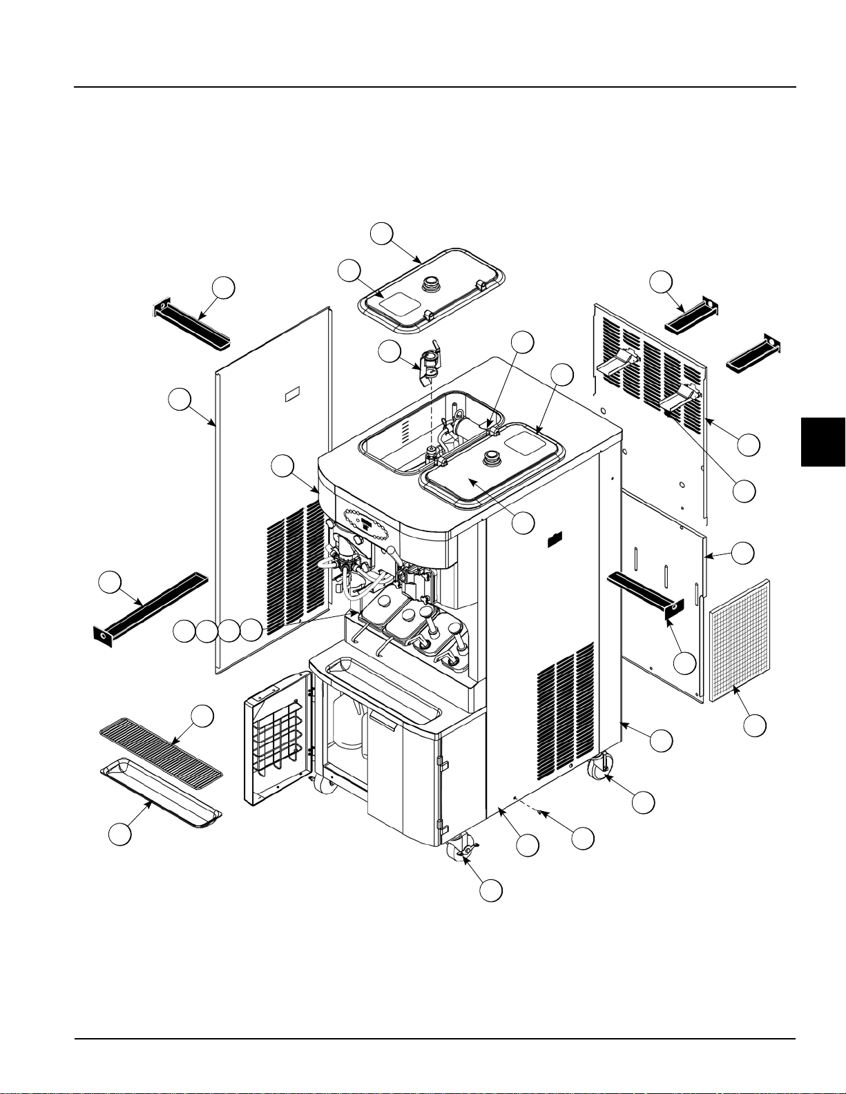
Exploded View
Operator Parts Identification
4
Operator Parts Identification
Figure 4-1
Model C606
4-1
Page 14
OPERATOR PARTS IDENTIFICATION
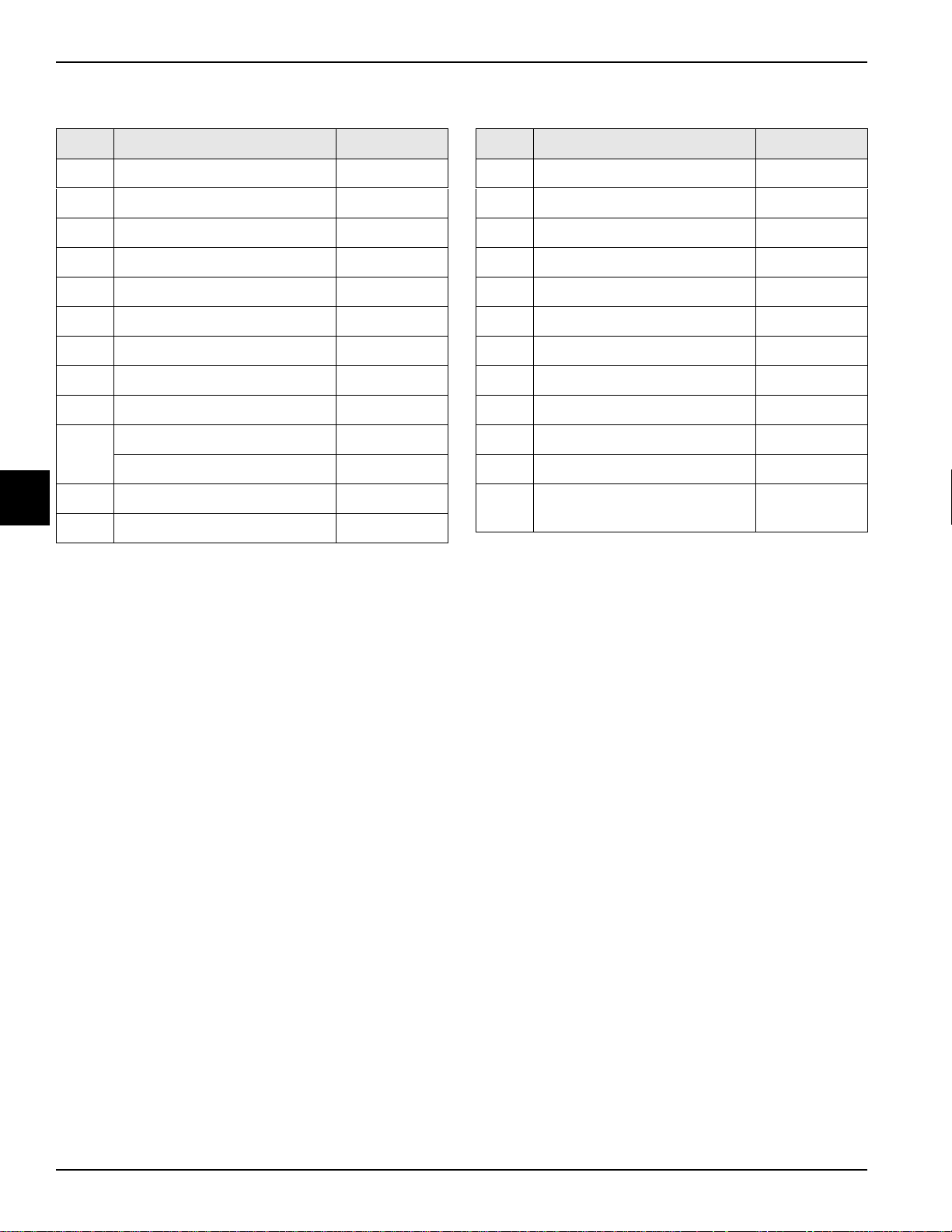
Exploded View
Item Description Part No.
1 Kit A.-Cover-Hopper X65368-SP
1a Label-Caution-Agitator 045191
2 Agitator A.-Mix Hopper-20 X44797
3 Pin-Retaining Hopper CVR 043934
4 Pan-Drip-Rear X56003
5 Panel-Rear-Upper 066724
6 Guide A.-Drip Pan-Mix Pump X48228
7 Panel-Rear-Lower 055959
8 Pan-Drip-Side X56005
Trim-Corner-Rear-R 056692
9
Trim-Corner-Rear-L 056693
4
10 Caster-4" 044106
11 Screw-1/4-20X3/8 011694
Item Description Part No.
12 Panel-Side Right 055950
13 Tray-Drip 033812
14 Shield-Splash 033813
15 Lid-Syrup Jar 042706
16 Jar-Syrup*Plastic 036573
17 Jar-Syrup*Stainless 036574
18 Ladle-1 oz 033637-1
19 Pan-Drip 19-1/2 Long 035034
20 Plate-DEC 056131-1
21 Panel-Side Left 055957
22 Filter-Air-18.00LX13.50HX.70 052779-3
23 Caster-4" SWV 3/4-10 Stem
w/ Brake
046437
4-2
Model C606
Operator Parts Identification
Page 15
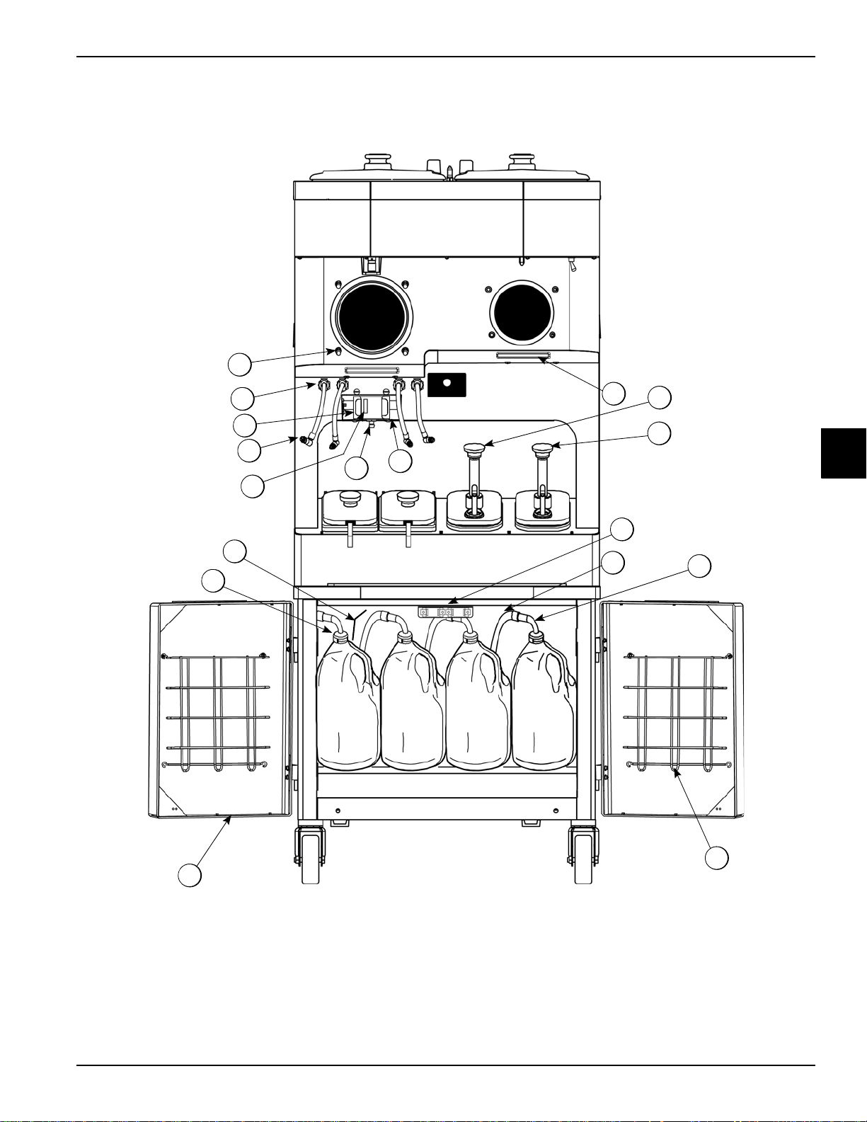
Front View
12
11
10
6
7b
7c
8a
8
9
1
2
3
4
5
7
7a
9a
OPERATOR PARTS IDENTIFICATION
4
Operator Parts Identification
Figure 4-2
Model C606
4-3
Page 16
OPERATOR PARTS IDENTIFICATION
Front View
Item Description Part No.
1 Stud-Nose Cone 055987
2 Fitting-Panel Mount QD 056674
3 Clip-Spring-Cup Holder 068394
4 Line A.-Syrup Door X59304
5 Sensor A.-Pyroelectric X59268-SER
Kit A.-Syrup Door
(magnetic catch)
Screw-6-32X3/8 SLTD (4) 002201
Magnet-Catch Assy. (2) 016121
6
Nut-10-32 Flange Locknut (4) 020983
Screw-10-32X3/8 SLTD (4) 024298
Handle-Door Short (2) 065933
4
Bracket-Magnet Door (1) 065934
Fitting A.-Syrup Jug 36" X53353-BLU
Fitting A.-Syrup Jug 36" X53353-BRN
7
Fitting A.-Syrup Jug 36" X53353-RED
X65932
Consists of:
Item Description Part No.
Hose-Beverage 3/8"ID X 5/8 053052-36
7b
Tube A.-Syrup Pick Up X53175
7c
Ferrule-.625 ID NP Brass 053036
*7d
Fitting-Peristaltic Pump 054526
*7e
O-ring-.500 OD X .070W (50 to
*7f
bag)
Line A.-Syrup (for use with bag
*
syrup system)
Door A.-Cabinet X58607-SER
8
Basket-Door-Wire 059144
8a
Holder A.-25DCC PYR SNS X69102
*9
Screw-Adjustment-5/16-18 051574
*9a
Pump A.-Syrup-Heated- BRN X53800-BRN
10
Pump A.-Syrup-Heated- Tan X53800-TAN
11
Gasket-Drip Lip 036435
12
*Not Shown
024278
X58450
Fitting A.-Syrup Jug 36" X53353-WHT
Cap-Ultimate Syrup 053040-BLU
Cap-Ultimate Syrup 053040-RED
7a
Cap-Ultimate Syrup 053040-BRN
Cap-Ultimate Syrup 053040-WHT
4-4
Model C606
Operator Parts Identification
Page 17
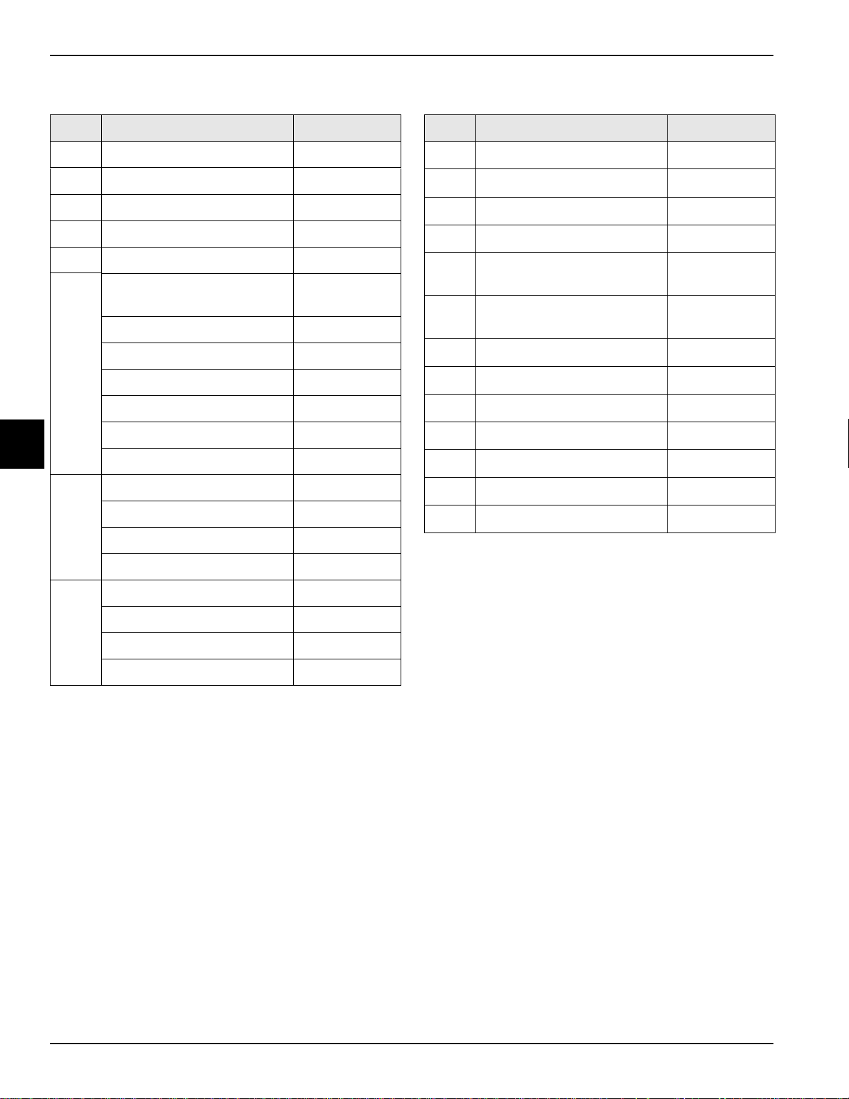
Syrup Cabinet View
11
9
4
1
6
12
7e
7a
7d
7b
7c
5
10
8a
8
3
2
OPERATOR PARTS IDENTIFICATION
Item Description Part No.
1 Shelf-Syrup 056016
2 Pump-Peristaltic 052916
3 Motor-Gear 161 RPM/ Short Shaft 058725-SER
4 Basket-Door-Wire 059144
5 Block-Hinge 058613
6 Block-Hinge 058614
Figure 4-3
Item Description Part No.
7c W asher-#4 Ext Tooth Lock 043075
7d Screw-6-32X3/8 SLTD BIND 002201
7e Bracket-Magnet Door 065934
8 Handle-Door Short 065933
8a Screw-10-32X3/8 SLTD TRUS 024298
9 Nut-10-32 Flange Locknut 020983
4
*7a Magnet-Catch Assy. 016121
7b Screw-4-40x3/8 Socket Cap 058317
Operator Parts Identification
*Prior to S/N K4091994, use 058630 Latch-Door-Magnetic.
Model C606
10 Screw-10-32X3/8 SLTD 006749
11 Washer-#8 Ext Tooth Lock 000964
12 Screw-8-32X1/4 SLTD Round 016540
4-5
Page 18
OPERATOR PARTS IDENTIFICATION
1
2
5
4
3
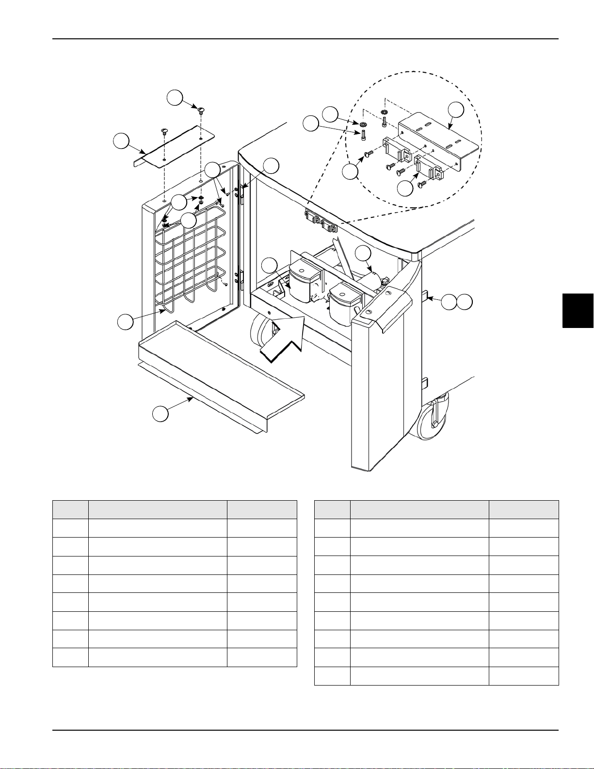
Syrup Pump and Tubes
4
Item Description Part No.
1 Pump-Peristaltic 052916
Kit A.-Peristaltic Pump Tube
(1 Tube Kit)
2
Kit A.-Peristaltic Pump Tube
(4 Tube Kit)
X54978
X54979
Figure 4-4
Item Description Part No.
3 Ferrule- .625 ID 053036
4 Fitting-Peristaltic Pump 054526
5 O-ring 1/2 OD x .070 024278
*6 Line A.-Syrup X62426-8
*Not Shown
4-6
Model C606
Operator Parts Identification
Page 19
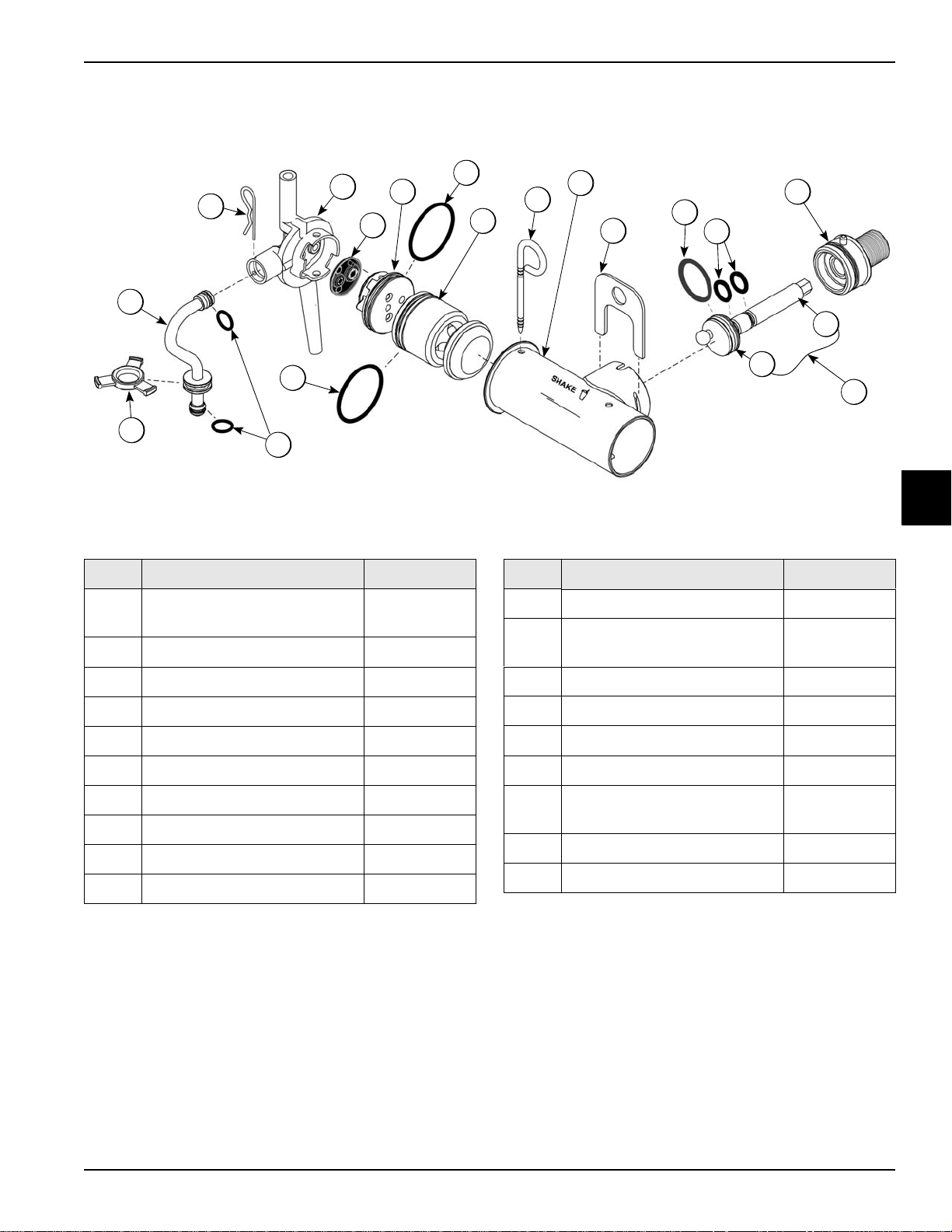
X57028-XX Pump A.—Mix Simplified - Shake
13b
14
13d
13c
13a
12
1
10
9
8
7
6
5
11
4
3
2
13
4
OPERATOR PARTS IDENTIFICATION
Item Description Part No.
1–7 Pump Assembly-Mix Simplified
Shake
1 Cylinder-Pump Hopper Shake 057944
2 Pin-Retaining X55450
3 Piston-Pump-Simplified 053526
4 O-ring-2-1/8 OD X .139W-#225 020051
*5 Cap-Valve Body Shake 056873-10
6 Gasket - Simplified Pump Valve 086097
7 Adaptor - Mix Inlet - Shake Blue 054944
8 Pin-Cotter-Hairpin-1/8DIA 044731
9 Tube A.-Feed Tube-SHK X55973
X57028-10
Figure 4-5
*Standard Cap-Valve Body Shaft is -10. A vailable in other sizes.
X55973 Sleeve A.-Mix Pump
Item Description Part No.
10 Ring-Check-Feed-Tube 056524
11 O-ring-11/16ODX.103W-Red
(50 to bag)
12 Clip-Retainer-Mix Pump 044641
13 Shaft A.-Drive-Mix Pump-Hopper X41947
13a Crank-Drive-Hopper Mix Pump 039235
13b Shaft-Drive-Mix Pump- Hopper 041948
13c O-ring-1-3/4 OD X .139W
(25 to bag)
13d O-ring 1/2 ID X .139W (25 to bag) 048632
14 Sleeve A.-Mix Pump X44761
016132
008904
4
Operator Parts Identification
Model C606
4-7
Page 20
OPERATOR PARTS IDENTIFICATION
13b
14
13d
13c
13a
12
1
4
10
9
8
7
6
5
10
4
3
2
13
11
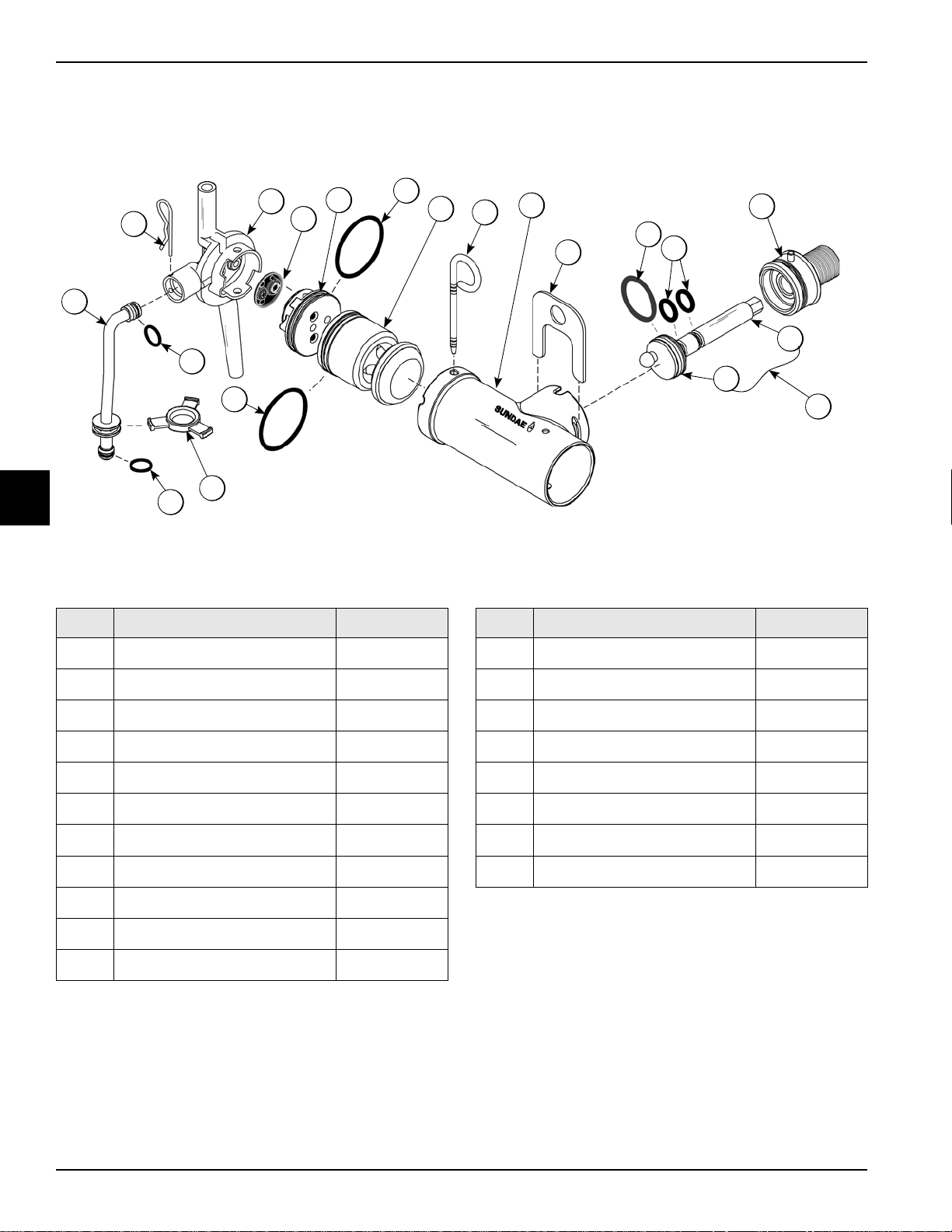
X57029-XX Pump A.—Mix Simplified - Soft Serve
4
Item Description Part No.
1–7 Pump A.-Mix Simplified S.S.
1
Cylinder-Pump Hopper Softserve
2
Pin-Retaining
3
Piston-Pump-Simplified
4
O-ring-2-1/8 OD X .139W-#225
5
Cap-Valve Body SS
6
Gasket-Simplified Pump Valve
7
Adaptor-Mix Inlet-SS-Red
8 Pin-Cotter-Hairpin-1/8DIA
9
Tube A.-Feed Tube-SS
X57029-12
057943
X55450
053526
020051
056874-12
086097
054825
044731
X55974
Figure 4-6
*Note: The Standard Pump is X57029-12. Overrun can be
changed higher or lower by substituting the valve body cap. The
higher the (-), the higher the overrun.
Item Description Part No.
11 Ring-Check-Feed-Tube
12 Clip-Retainer-Mix Pump
13 Shaft A.-Drive-Mix Pump- Hopper
13a
13b
13c
13d
14 Sleeve A.-Mix Pump *HT
Crank-Drive-Hopper Mix Pump
Shaft-Drive-Mix Pump- Hopper
O-ring-1-3/4 OD X .139W
O-ring 1/2 ID X .139W
056524
044641
X41947
039235
041948
008904
048632
X44761
10
O-ring-11/16ODX.103W-Red
016132
4-8
Model C606
Operator Parts Identification
Page 21
OPERATOR PARTS IDENTIFICATION
2
3
4
5
6
7
8
2
1
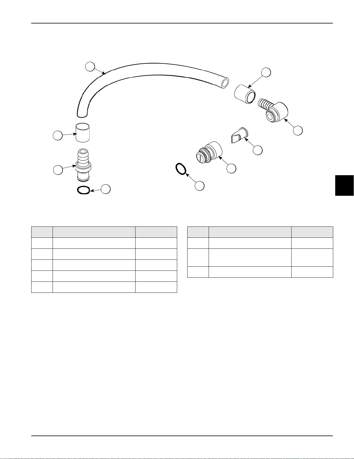
X59304 Syrup Line Assembly—Thin Viscosity Syrup
Item Description Part No.
1 Tube-Nylobrade 3/8IDX5/8 500038-9
2 Ferrule-.650 ID NP Brass 029834
3 Fitting-Syrup Elbow 056651
4 Valve-Check-Duckbill 500598
5 Fitting-Syrup Nose .075 Slot 056649
Figure 4-7
Item Description Part No.
6 O-ring-11mm ID X 2mm W Green 053890
7 O-ring-11mm ID X 2mm W Green
(25 to bag)
8 Insert-QD-CPC-3/8 Barb 056675
053890
4
Operator Parts Identification
Model C606
4-9
Page 22
OPERATOR PARTS IDENTIFICATION
2
3
4
5
6
7
8
2
1
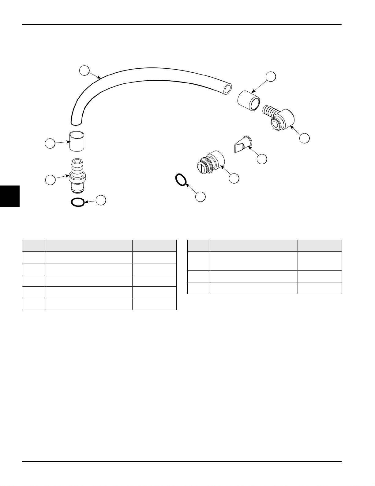
X56652 Syrup Line Assembly—Thick Viscosity Shake Syrup (Optional)
4
Item Description Part No.
1 Hose-Beverage 053052-9
2 Ferrule-.625 ID 053036
3 Fitting-Syrup Elbow 056651
4 Valve-Check Duckbill 500598
5 Fitting-Syrup Nose (Large Slot) 056650
Figure 4-8
Item Description Part No.
6 O-ring-11 mm Green
(Syrup Hole Plug)
7 O-ring 500205
8 Fitting-Barb 056675
053890
4-10
Model C606
Operator Parts Identification
Page 23
OPERATOR PARTS IDENTIFICATION
1
2
3
4
3
5
6
7
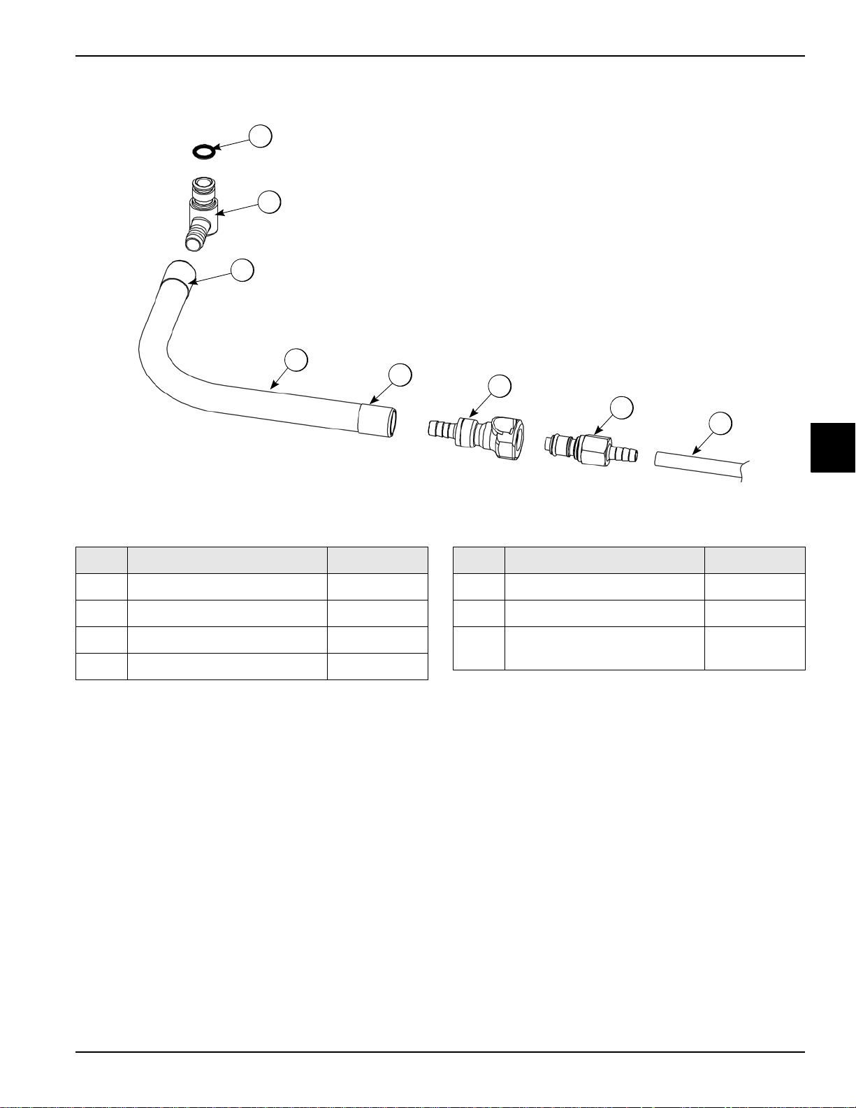
X58450 Syrup Line Assembly—Syrup-in-Bag Option
Item Description Part No.
1 O-ring 1/2 OD X .070 024278
2 Fitting-Male 054526
3 Ferrule- .625 ID NP Brass 053036
4 Hose-Beverage 3/8 ID 053052-36
Figure 4-9
Item Description Part No.
5 Coupling-QD Female 3/8 058451
6 Coupling-QD Male 1/4 Barb 058452
7 Tube-Vinyl 3/16 ID X 1/16 W
(R30314)
020940-8
4
Operator Parts Identification
Model C606
4-11
Page 24
OPERATOR PARTS IDENTIFICATION
1
21
6
3
4
6
5
4a
3a
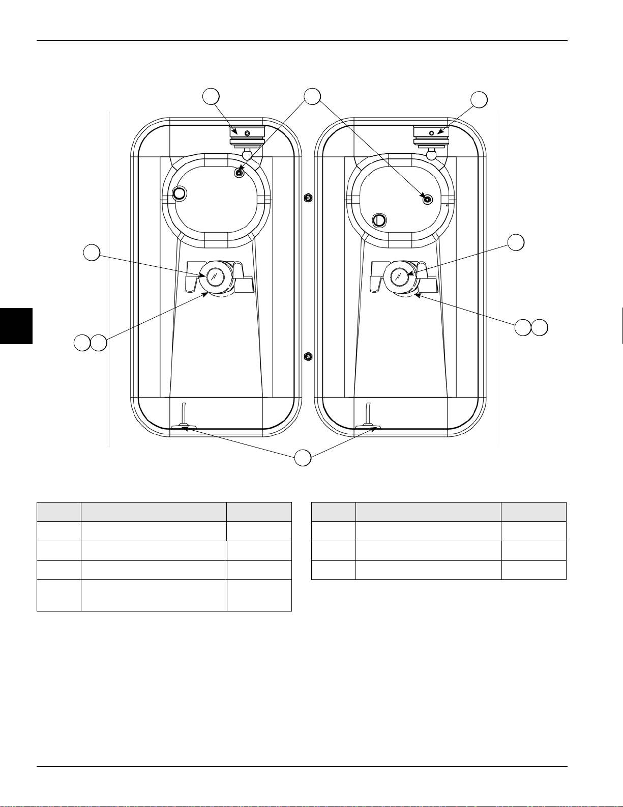
Mix Hopper—Top View
4
Item Description Part No.
1 Sleeve A.-Mix Pump X44761
2 Probe A.Mix Out X41348
3 Housing A.-Agitator (Shake) X51664
3a4aMagnet A.-Agitator-Inner X41733
Figure 4-10
Item Description Part No.
4 Housing A.-Agitator (Soft Serve) X51661
5 Probe A.-Mix Low X42077
6 Cap-Magnet 080826
4-12
Model C606
Operator Parts Identification
Page 25
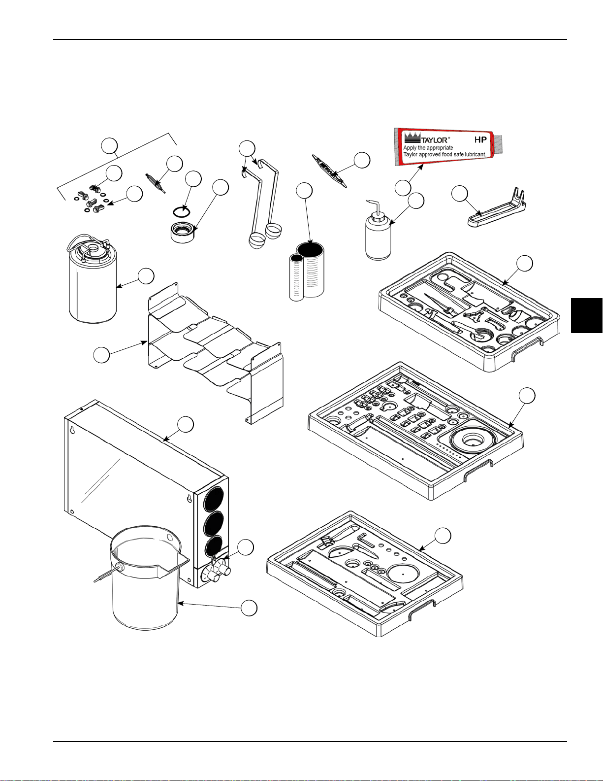
Accessories
10
11
12
8
9
7
6
4
2
3
1c
1a
1b
16
14
15
5
14a
13
1
OPERATOR PARTS IDENTIFICATION
4
Operator Parts Identification
Figure 4-11
Model C606
4-13
Page 26
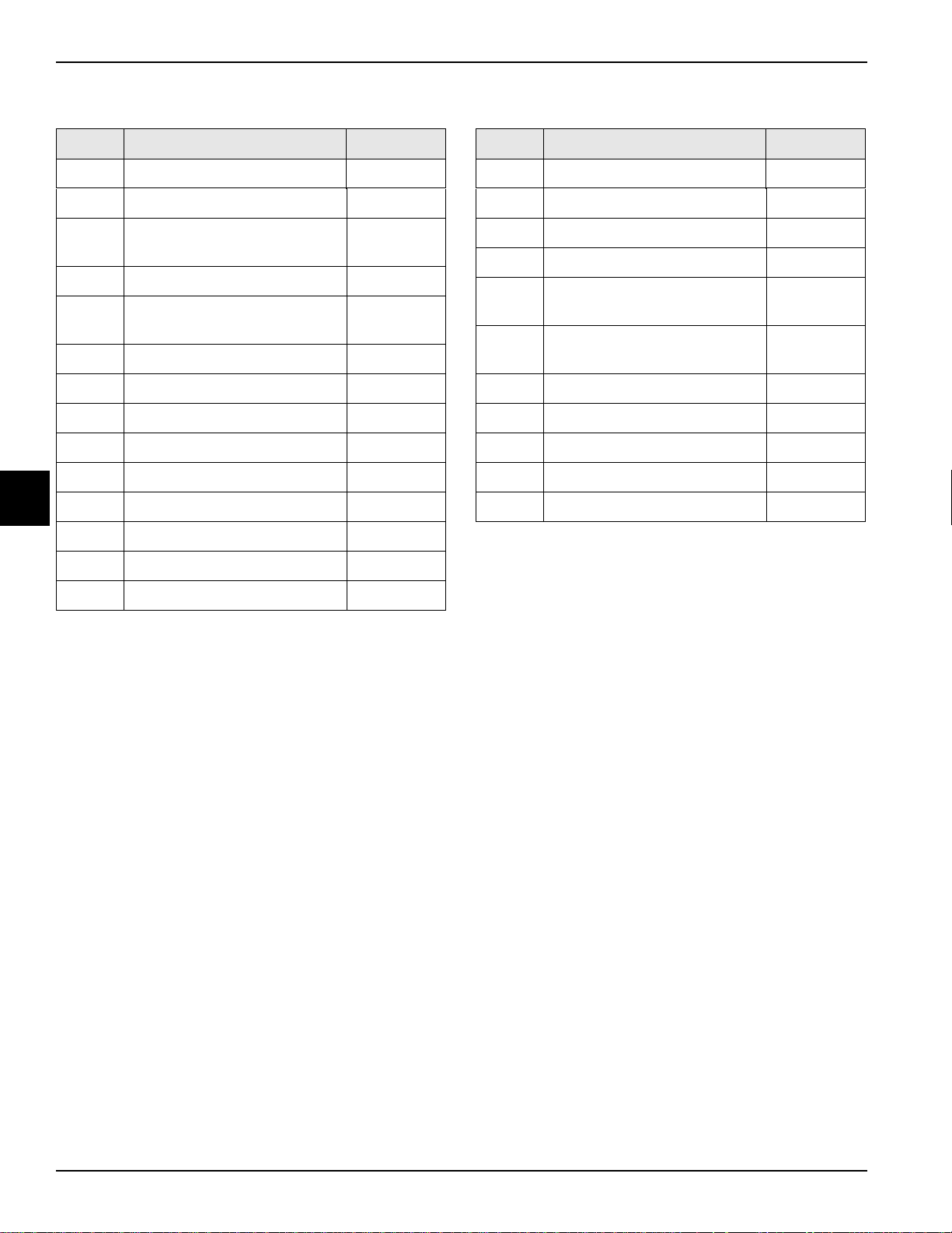
OPERATOR PARTS IDENTIFICATION
Accessories
4
Item Description Part No.
1 Kit A.-Syrup Plug Kit TTS X58474
1a Plug-Syrup Port TTS 053867
1b O-ring-11mm ID X 2mm W Green
(25 to Bag)
1c Tool-Seal Install-Remove 035460
2 O-ring-1-11/16 OD X.139W
(25 to bag) (Draw Valve Cap)
3 Cap A.-V alve-Draw X54704
4 Ladle-1 oz-120D Bend 033637-1
5 Cup-Divided Syrup 017203
6 Tool-O-ring Removal 048260-WHT
7 Lubricant-Taylor Hi PERF 048232
8 Bottle-Wash-Plastic 044818
9 Tool-Mix Pump Shaft Removal 057167
10 Tray-Parts-Pump-SIMPL 056525
053890
041923
Item Description Part No.
12 Tray-Parts-SS Side 059087
13 Pail-10 qt. 013163
14 Dispenser A.-Cup-2 Cone X56121
14a Baffle-Rubber Cone 052193
15 Tray A.-Syrup (Optional Syrup in
Bag System)
16 Tank-Syrup 4qt. PSD (Optional 4
Tank Syrup System)
* Kit A.-Peristaltic Pump Tube X54978
* Kit A.-Topping Pump Spares X53795
* Kit A.-Tune Up Blade X49463-94
* Deflector-Blower Exhaust 047912
* Box-Tool 15 inch Plastic 058669
*Not Shown
X59143
056673
11 Tray-Parts-Shake Side 059088
4-14
Model C606
Operator Parts Identification
Page 27
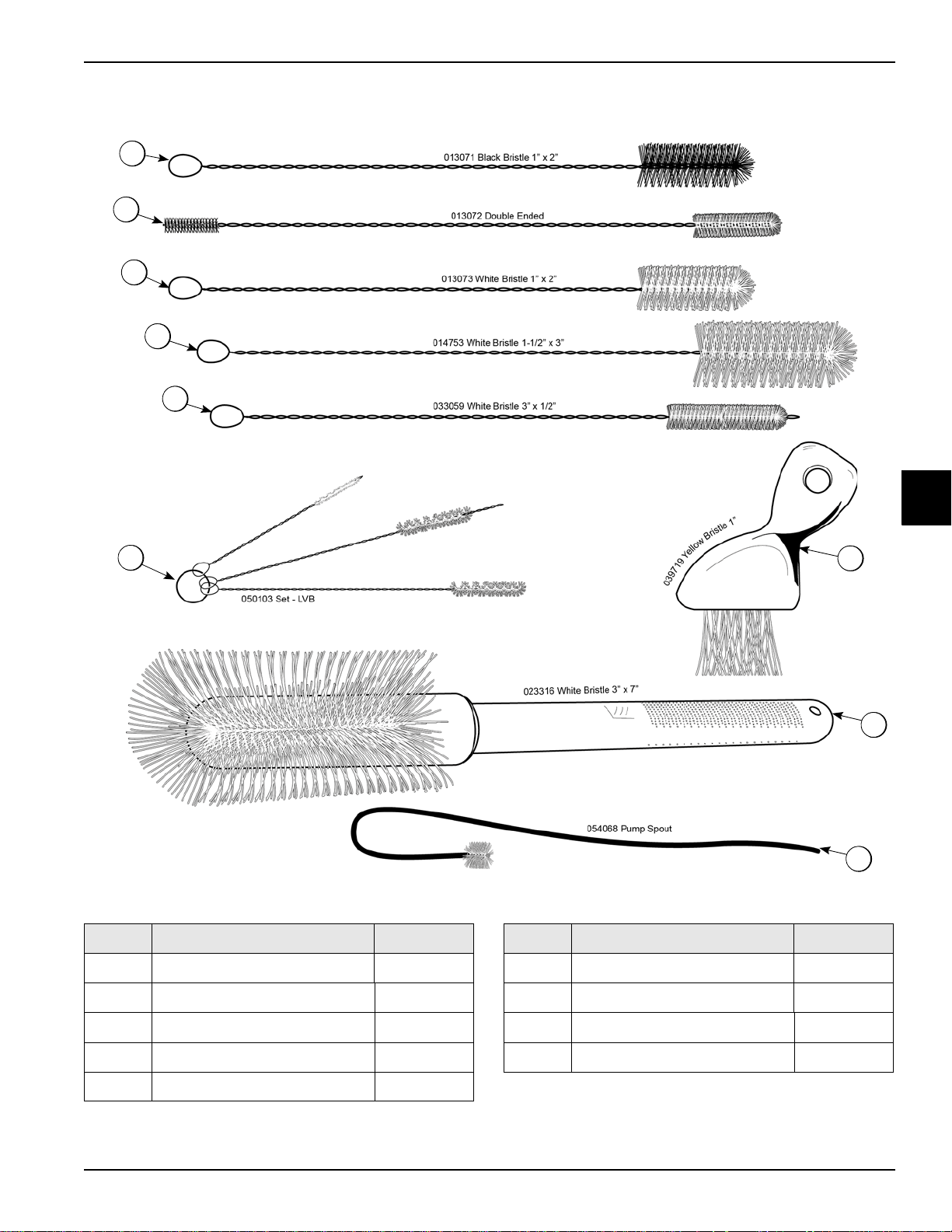
X44127 Brush Kit Assembly
1
2
3
4
5
6
7
8
9
OPERATOR PARTS IDENTIFICATION
4
Item Description Part No.
Figure 4-12
Item Description Part No.
1 Black Bristle Brush 013071
2 Double End Brush 013072
3 White Bristle Brush (1” x 2”) 013073
4 White Bristle Brush (1-1/2” x 3”) 014753
5 White Bristle Brush (1/2” x 3”) 033059
Operator Parts Identification
Model C606
6 Brush Set (3) 050103
7 Yellow Bristle Brush 039719
8 White Bristle Brush (3” x 7”) 023316
9 Brush-Pump Spout 054068
4-15
Page 28
OPERATOR PARTS IDENTIFICATION
5
2f
2d
2b
2a
2c
2e
2g
1
3
4
2
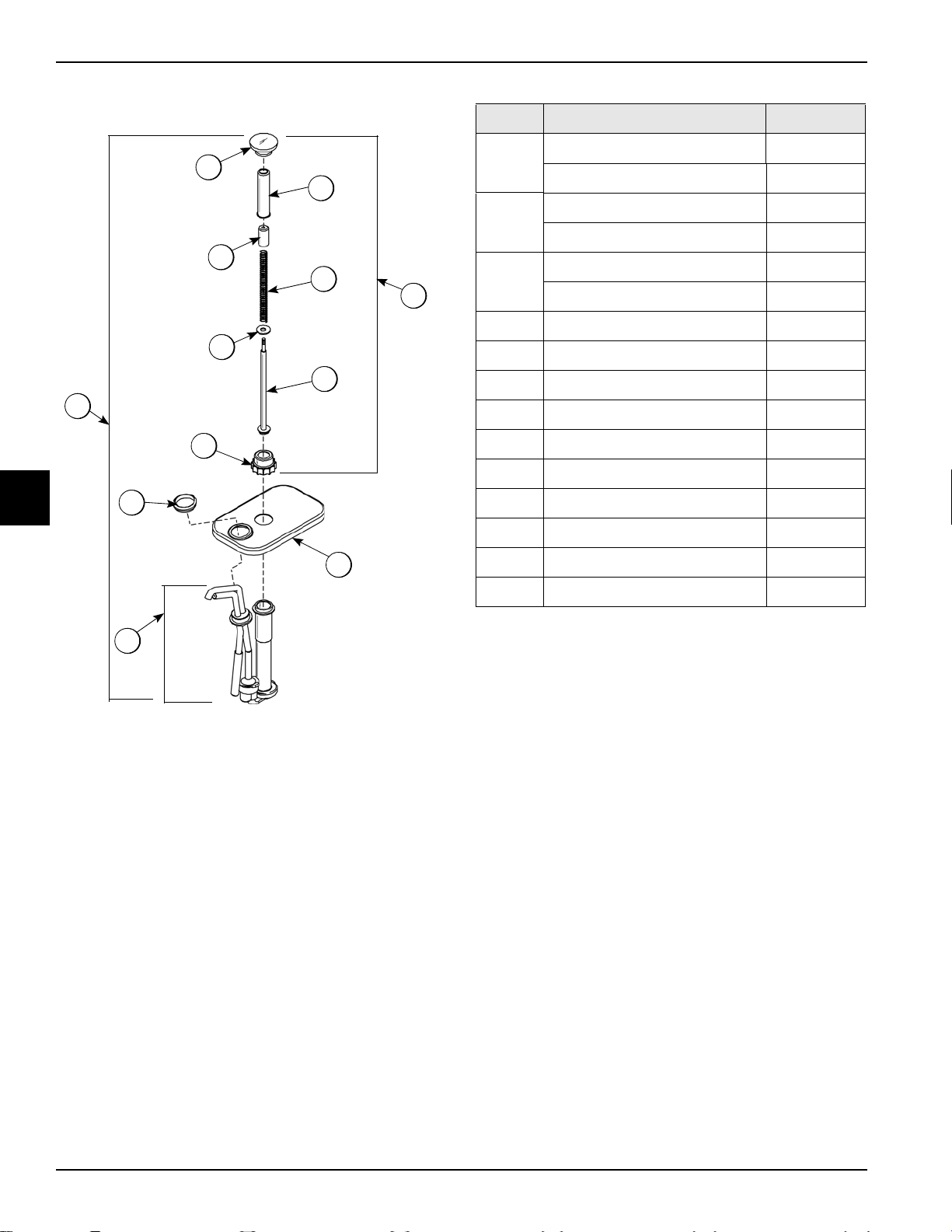
X53800-BRN/TAN Syrup Pump
4
Item Description Part No.
Pump A.-Syrup-Heated X53800-BRN
1
Pump A.-Syrup-Heated X53800-TAN
Plunger A.-Brown X36576-BRN
2
Plunger A.-T an X36576-TAN
Knob-Plunger Brown- Syrup Pump 032762-BRN
2a
Knob-Plunger Tan-Syrup Pump 032762-TAN
2b Tube-Plunger 032757
2c Insert-Plunger 032758
2d Spring-Plunger-Syrup Pump 032761
2e Washer-Nylon 032760
2f Plunger 036578
2g Seal A. X33057
*2h Nut-Plunger 036577
3 Nut-Lock-Syrup Pump 039680
4 Pump A.-Syrup Heated Shallow X53798-SER
5 Lid 036579
Note: Shown for reference only. Not supplied with new
machines.
*Not Shown
Figure 4-13
4-16
Model C606
Operator Parts Identification
Page 29
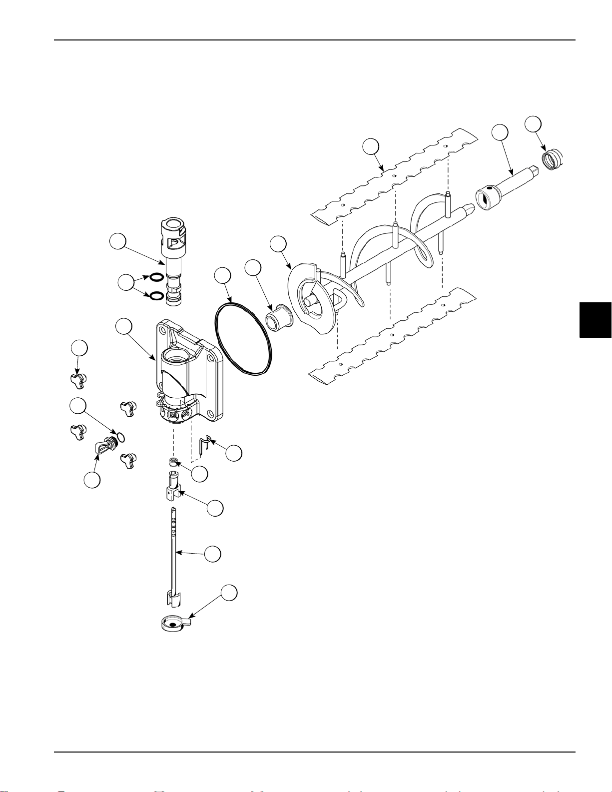
Beater Door Assembly—Shake Side
2
1
3
4
17
16
8
7
9
10
13
11
12
14
15
6
5
OPERATOR PARTS IDENTIFICATION
4
Operator Parts Identification
Figure 4-14
Model C606
4-17
Page 30
OPERATOR PARTS IDENTIFICATION
Beater Door Assembly—Shake Side
4
Item Description Part No.
1 Seal-Drive Shaft 032560
2 Shaft-Beater 7 qt. 050985
3 Blade-Scraper 16” 041103
4 Beater A.-7 qt. Fluted Blade X50958
5 Bearing-Door Front 055605
6 O-ring 6” (Freezer Door) 033493
7 Door A.-Shake Side X55825SER2
8 Nut-Stud-Short 055989
9 O-ring Syrup Port 11 mm 053890
Item Description Part No.
10 Plug-Syrup Port 053867
11 Retainer-Syrup Valve 054554
12 Seal-Spinner Shaft 084696
13 Spinner 034054
14 Blade A.-Spinner X59331
15 Cap-Restrictor 033107
16 O-ring 1-1/16 OD X .139 W
(Draw V a lve)
17 V alve A.-Draw 059000
020571
4-18
Model C606
Operator Parts Identification
Page 31

Beater Door Assembly—Soft Serve Side
14
13
11
12
10
9
8
7
6
5
2
1
4
3
5
16
15
OPERATOR PARTS IDENTIFICATION
Item Description Part No.
1 Seal-Drive Shaft 032560
2 Shaft-Beater 032564
3 Beater A.-3.4qt-1 Pin X46231
4 Blade-Scraper-Plastic 9-13/16L 084950
5 Kit A.-Beater-Front Shoes-Bearing X50350
6 Baffle -Threadess Molded 087 708
7 Gasket-Door HT 4"-Double 048926
8 Pin-Handle-SS 055819
9 Door A.-1SP 3.4QT Threadless X87683
Figure 4-15
Item Description
10 Nut-Stud-Black-1.00 055989
1 1 Screw-Adjustment-5/16-24 056332
12 Nut-5/16-24 Finished Hex 029639-BLK
13 O-ring-1/4 OD X .070W 50 DURO
(25 to Bag)
14 Handle A.-Draw X56421-1
15 O-ring-7/8 OD X .103W
(100 to Bag)
16 V alve A.-Draw X55820
015872
014402
4
Operator Parts Identification
Model C606
4-19
Page 32

OPERATOR PARTS IDENTIFICATION
1
2 3
4
5
7
8
9
10
11
12
13
14
15
16
17
18
6
059088 Parts Tray—Shake Side
4
Item Description Part No.
1 Beater A.-7 qt. X50958
2 Blade-Scraper-16” 041103
3 Shaft-Beater 7 qt. 050985
4 Seal-Drive Shaft 032560
5 Nut-Stud 055989
6 O-ring-Syrup Port 11mm ID Green 053890
7 Plug-Syrup Port 053867
8 Spinner 034054
9 Blade A.-Spinner X59331
10 Seal-Spinner Shaft 084696
Figure 4-16
Item Description Part No.
1 1 Cap-Restrictor 033107
12 V alve A.-Draw X57169
13 Valve-Check Duckbill 500598
14 Bearing-Door Front 055605
15 O-ring-1-1/16 OD (Draw Valve) 020571
16 Fitting-Syrup Nose See pages
17 Retainer-Syrup Valve 054554
18
4-9 and 4-10
O-ring 6”-Door 033493
Door A.-Shake X55825SER2
4-20
Model C606
Operator Parts Identification
Page 33

059087 Parts Tray—Soft Serve Side
9
8
76
5
4
3
2
1
14
13
12
11
10
OPERATOR PARTS IDENTIFICATION
Item Description Part No.
1 Handle A.-Draw X56421-1
2 Pin-Pivot 055819
3 Bearing-Front 050348
Figure 4-17
Item Description Part No.
8 Door A.-w/Baffle X57332-SER
9 Shoe-Front Helix- Front 084108
10 Drive Shaft 032564
4
4 Nut-Stud 055989
5 O-ring (Draw Valve) 014402
6 Gasket (Freezer Door) 048926
7 Valve A.-Draw X55820
Operator Parts Identification
Model C606
11 Seal-Drve Shaft 032560
12 Blade-Scraper-Plastic 9-13/16L 084950
13 Beater A. X46231
14 Shoe-Front Helix- Rear 084109
4-21
Page 34

OPERATOR PARTS IDENTIFICATION
5
4
3
2
1
16
15
14
13
12
11
10
9
7
8
6
056525 Parts Tray—Simplified Pump
4
Figure 4-18
Shake Side Soft Serve Side
Item Description Part No.
1 Clip-Mix Pump Retainer 044641
2 Cylinder-Pump-Hopper Shake 057944
3 Pin-Retaining X55450
4 Piston 053526
5 Pin-Cotter 044731
6 O-ring 2-1/8” OD - Red 020051
7 Cap-Valve 056873-XX
8 Gasket-Simplified Pump Valve 086097
9 Adaptor-Mix Inlet Shake-Blue 054944
10 Ring-Check .120 OD 056524
11 Shaft A.-Drive Mix Pump X41947
12 O-ring-Drive Shaft 048632
13 Tube A.-Feed-Hopper Shake X55973
Item Description Part No.
1 Clip-Mix Pump Retainer 044641
2 Cylinder-Pump-Hopper- Soft Serve 057943
3 Pin-Retaining X55450
4 Piston 053526
5 Pin-Cotter 044731
6 O-ring 2-1/8” OD - Red 020051
7 Cap-Valve 056874-XX
8 Gasket-Simplified Pump Valve 086097
9 Adaptor-Mix Inlet Soft Serve-Red 054825
10 Ring-Check .120 OD 056524
1 1 Shaft A.-Drive Mix Pump X41947
12 O-ring-Drive Shaft 048632
13 Tube A.-Feed-Hopper Soft Serve X55974
14 O-ring 1-3/4 008904
15 O-ring-11/16 OD - Red 016132
4-22
Model C606
14 O-ring 1-3/4 008904
15 O-ring-11/16 OD - Red 016132
16 Agitator A.-Mix Hopper X44797
Operator Parts Identification
Page 35

Section 5
4
3
2
1
16
15
13
12
11
10
9
8
7
5
6
14
User Interface
Item Description
1 Key—Shake
2 Display—Vacuum Fluorescent Menu (VFD)
3 Key—Menu (Entry/Exit)
4 Keys—Soft Serve
5 Indicator Light—Mix Out
6 Switch—Power
7 Standby—Soft Serve
8 Standby—Shake
Figure 5-1
Item Description
9 Keys—Topping Heaters
10 Display—LED (Brush Clean Countdown)
11 Key—Calibrate Menu
12 Key—Flavor Selection
13 Key—Vanilla Flavor
14 Key—Strawberry Flavor
15 Key—Chocolate Flavor
16 Indicator Light—Mix Low
Note: See “Manager's Menu” on page 5-7 for additional key
functions when the Calibration or Manager's Menu is displayed.
5
User Interface
Model C606
5-1
Page 36

USER INTERFACE
Symbol Definitions
To better communicate in the international arena,
symbols have replaced words on many of our operator
keys, switches, functions, and fault indicators. Your
Taylor machine is designed with these international
symbols.
The following chart identifies the symbol definitions:
= Auto
=Heat Cycle
= Wash
= Mix Pump
= Standby (Shake)
= Standby (Soft Serve)
= Flavor Selection
5
= Mix Low
Vacuum Fluorescent Display
The vacuum fluorescent display (VFD) is located on the
front control panel. During normal operation the display is
blank. The display is used to show menu options and
notifies the operator if a fault is detected. The display will
indicate the temperature of the mix in each hopper.
Indicator Lights
Mix Low—When the Mix Low indicator light is
illuminated, the mix hopper has a low supply of mix and
should be refilled as soon as possible.
Mix Out—When the Mix Out indicator light is
illuminated, the mix hopper has been almost completely
exhausted and has an insufficient supply of mix to
operate the freezer. At this time, the Auto mode is locked
out and the freezer will be placed in the Standby mode.
To initiate the refrigeration system, add mix to the mix
hopper and press the Auto key
automatically begin operation.
. The freezer will
Heat Cycle Key
= Mix Out
= Topping Heater-Left
= Topping Heater-Right
= Calibrate
= Menu Display
Power Switch
When placed in the ON position, the power switch allows
control panel operation.
When the Heat Cycle key is illuminated, the freezer
is in the process of a heat cycle. The Heat Cycle key ma y
be selected to start a heat cycle following a freezer soft
lock condition.
For some models, the Heat Cycle key can be selected to
manually start a heat cycle at any time.
Brush-Clean Countdown—Displays the number of days
before the next brush-cleaning is required. When the
display has counted down to 1, the machine must be
disassembled and brush-cleaned within 24 hours.
5-2
Model C606
User Interface
Page 37

USER INTERFACE
Reset Mechanism
The Reset button is located in the service panel at the
rear of the machine. (See Figure
beater motor from overloading. Should an overload
occur, the reset mechanism will trip. To properly reset the
freezer, place the power switch in the OFF position.
Press the Reset button firmly. Turn the power switch to
the ON position. Press the Wash key
the freezer's performance.
5-2.) It protects the
and observe
Adjustable Draw Handle
This machine features an adjustable draw handle to
provide the best portion control, giving a better,
consistent quality to your product and controlling costs.
The draw handle should be adjusted to provide a flow
rate of 5 oz. to 7-1/2 oz. (142 g to 213 g) of product by
weight per 10 seconds. To increase the flow rate, tighten
the screw. To decrease the flow rate, loosen the screw.
After setting the flow rate, tighten the jam nut to secure
the adjustment screw. (See Figure
5-3.)
Figure 5-2
CAUTION! DO NOT use metal objects to press
the reset button. Failure to follow this instruction may
result in electrocution.
If the beater motor is turning properly, press the Wash
key
resume normal operation. If the freezer shuts down
again, contact your authorized service tec hn i cian.
to cancel the cycle. Press the Auto key to
Air/Mix Pump Reset Mechanism
The Reset button for the pump is located in the service
panel at the rear of the machine. (See Figure
reset protects the pump from an overload condition.
Should an overload occur, the reset mechanism will trip.
To reset the pump, press the Reset button firmly.
5-2.) The
Figure 5-3
Shake Fill Level Adjustment
The portion control sensor located under the cup holder
can be adjusted to fill the cup to the desired level. If the
fill level is too low, or the cup is overfilling, it may be
necessary to adjust the sensor position. (See Figure
Figure 5-4
1. Using a crescent wrench, loosen the locking nut on
the screw adjuster below the sensor.
5-4.)
5
User Interface
2. Turn the adjustment screw clockwise to raise the fill
3. Once the desired fill level is achieved, tighten the
Model C606
level, or counterclockwise to lower the fill level.
locking nut.
5-3
Page 38

USER INTERFACE
VFD Screens
The vacuum fluorescent display (VFD) located in the
center of the control panel is normally blank during the
daily operation of the machine. The display is activated
when the Calibrate key
selected. The display screen will also alert the operator of
specific faults detected by the control.
or the Manager's Menu is
Power Up
When the machine is powered, the control system will
initialize to perform a system check. There are four types
of data that the system will check when the control is
initializing: Lamp Test, Lockout Data, Configuration Data,
and System Data.
Lamp Test: The control and software version is displayed
and all of the LEDs on the display panel are illuminated.
5
The SAFETY TIMEOUT screen will be displayed with the
alarm on, for 60 seconds or until any control key is
selected.
After the safety timeout has been completed and the
power switch is OFF, the status screen will display. When
the brush-clean requirements have been met, the
following screen will display:
If a brush-cleaning was not completed, the status screen
will display the current hopper temperature, barrel
temperature, and 5-minute brush-clean timer.
Power Switch ON
When the power switch is placed in the ON position, the
control panel keys become operative. The VFD will either
be blank or indicate that the machine has been cleaned.
Following the lamp test, three separate screens will
appear during initialization.
Initializing . . . . Lockout Data
Initializing . . . . Config Data
Initializing . . . . System Data
If the system detects corrupt data during the initializing,
the following display will alert the operator that the control
settings have changed:
Once the system has initialized, the number of days
remaining before the next required brush-cleaning is
indicated on the control panel, and the SAFETY
TIMEOUT screen is displayed with the alarm turned on.
Some models will continuously display the temperature
of each mix hopper when the power switch is in the ON
position.
5-4
Model C606
User Interface
Page 39

USER INTERFACE
Heat Treatment Cycle
The Heat Cycle keys on the control panel illuminate
throughout the heat treatment cycle. Two warning
messages will be displayed on the screen. DO NOT
DRAW will be displayed when the mix temperature is
below 130°F (54.4°C).
When the temperature of the mix is above 130°F
(54.4°C), the screen will display a message indicating
that hot product is in the machine.
Important! Do not attempt to draw product or
disassemble the machine during the he at trea tm e nt
cycle. The product is hot and under extreme pressure.
In the heat treatment cycle, the mix temperature in the
hoppers and freezing cylinders must be raised to 151°F
(66.1°C) within 90 minutes.
Heat Treatment Cycle Failure Messages
To comply with health codes, heat treatment system
freezers must complete a heat treatment cycle daily, and
must be disassembled and brush-cleaned a minimum of
every 14 days. Brush-cleaning is the normal disassembly
and cleaning procedure found in this manual. Failure to
follow these guidelines will cause the control to lock the
freezer out of the Auto mode.
Always comply with local guidelines for the maximum
number of days allowed between brush-clean cycles.
(See “BRUSH CLEAN CYCLE” on page 5-12.)
If the heat treatment cycle fails, the VFD will display a
failure message and return the freezer to the Standby
mode. A lock is defined as a special Standby mode of
operation which does not allow the machine to operate in
the Auto mode.
There are two types of freezer lock conditions that can
occur: hard lock and soft lock. A hard lock requires the
machine to be disassembled and brush-cleaned. A soft
lock can be corrected by either disassembling and
brush-cleaning the machine, or by starting another heat
treatment cycle.
Hard Lock: There are two causes of a hard lock failure.
• The brush-clean timer has elapsed (maximum se tting
of 14 days).
5
When the heating phase is complete, the freezer goes
into the holding phase of the cycle. The holding phase
will keep the temperature above 151°F (66.1°C) for a
minimum of 30 minutes.
The final phase of the heat treatment cycle is the cooling
phase. The freezer must cool the mix below 41°F (5°C)
within 2 hours.
When the entire heat cycle has been completed, the Heat
Cycle keys
machine will enter the Standby mode (Standby keys
and will illuminate). The machine can be
placed in Auto or left in Sta ndby.
will no longer be illuminated. The
Selecting the Wash key will display the
following screen.
• There has been a thermistor failure (freezing
cylinder, hopper, or glycol) during the heat treatment
process.
User Interface
Model C606
5-5
Page 40

USER INTERFACE
Selecting the Calibrate key will indicate which
thermistor caused the hard lock.
If the machine has hard locked and an attempt is made to
enter Auto mode, the machine will enter the Standby
mode and display the following message:
5
To restore the message that identified the reason for the
hard lock, turn the power switch to OFF for 5 seconds
and then return the power switch to the ON position. The
original message with the reason for the hard lock will be
displayed. The fault description can also be found in the
Manager's Menu.
The FREEZER LOCKED message will remain on the
display until the brush-clean requirements are fulfilled.
The freezer must be disassembled in order to activate
the 5-minute timer on the display screen. Once the timer
counts down to zero, the lockout is cleared.
If the reason for the soft lock has been corrected,
selecting the Heat Cycle key
initiates a heat
treatment cycle immediately . Selecting the W ash key
when the above message is displayed will hard lock the
machine, and brush-cleaning will be necessary.
The following are the variable messages for soft lock
failures that appear on the second line of the screen:
Table 5-1
POWER SWITCH
OFF
MIX OUT PRESENT There was a mix out condition present.
AUTO OR
STANDBY OFF
NO HEAT CYCLE
TRIED
The power switch was in the OFF position.
The machine was not in the Auto or
Standby mode.
A heat treatment cycle was not
attempted in the last 24 hours. (AUTO
HEAT TIME was advanced, a power
loss was experienced at the time the
cycle was to occur, or a heat cycle failure not due to a thermistor failure.)
If the following screen appears, a soft lock has occurred
during the heat treatment cycle:
Soft Lock: If a heat treatment cycle has not been
initiated within the last 24 hours, a soft lock failure will
occur. A soft lock allows the operator to cor rect the cause
of the soft lock. The operator has the option of either
starting another heat cycle or brush-cleaning the
machine.
When a soft lock occurs, the machine will go into the
Standby mode. The following message is displayed on
the screen. The reason for the soft lock is indicated on
the second line.
5-6
Model C606
A soft lock can also occur anytime during operation when
the hopper or freezing cylinder temperature rises above
59°F (15°C), rises and remains above 45°F (7°C) for
more than 1 hour, or rises and remains above
41°F (5°C) for more than 4 hours. If a produ ct ove r
temperature condition occurs during operation, the
following screen will appear:
User Interface
Page 41

USER INTERFACE
When one of these messages appears, automatic freezer
operation cannot take place until the freezer is
disassembled and brush-cleaned or has completed a
heat treatment cycle. Select the Heat Cycle key
start a heat cycle, or select the Wash key to
disassemble and brush-clean the machine.
Once the freezer is unlocked by starting a heat treatment
cycle, the Heat Cycle key
following message will be displayed on the screen:
If the Wash key is selected to clear the lockout by
brush-cleaning the machine, the FREEZER LOCKED
message will remain on the display until the brush-clean
requirements are fulfilled. The freezer must be
disassembled in order to activate the 5-minute timer on
the display screen. Once the timer counts down to zero,
the lockout is cleared.
will illuminate and the
to
Manager's Menu
The Manager's Menu is used to enter the operator
function displays. To access the Manager’s Menu, press
the center of the CONE symbol
(See Figure 5-5.)
Figure 5-5
The left (shake-side) Auto key , the Flavor Selection
key , and the Cone key will be illuminated when
the ACCESS CODE screen is displayed.
In the Menu program, the left (shake-side) Auto key ,
on the control panel.
5
To restore the message that identified the reason for the
soft lock, turn the power switch to OFF for 5 seconds,
and then return the power switch to the ON position. The
original message with the reason for the soft lock will be
displayed.
The FAULT DESCRIPTION can also be found in the
Manager's Menu.
Note: A record of heat cycle data and lockout history
can be found in the Manager's Menu.
Menu” on page 5-7.)
(See “Manager's Menu” on page 5-7.)
(See “Manager's
Flavor Selection key , and Calibr at ion key will
function as menu keys.
Auto —Increases the value above the cursor and is
used to scroll upward in text displays.
Flavor Selection —Decreases the value above the
cursor and is used to scroll downward in text displays.
Calibration —Advances the cursor position to the
right and is used to select menu options.
Note: You will not be able to dispense shakes while
accessing the Manager's Menu options, except when the
CURRENT CONDITIONS screen is displayed.
The soft serve side will continue operation in the mode it
was in when the Manager’s Menu was selected.
However, the soft serve side control keys will not be
illuminated and are nonfunctional when the Manager's
Menu or Calibration Menu is displayed.
User Interface
Model C606
5-7
Page 42

USER INTERFACE
The control keys for both sides are functional in the
Manager's Menu when the CURRENT CONDITIONS
screen is displayed.
page 5-19.)
(See “CURRENT CONDITIONS” on
Entering Access Code
With the ACCESS CODE screen on the display, use the
Auto
code number in the cursor position. When the correct
number is selected, press the Calibration key
move the cursor to the next number position.
The access code for the Manager Menu is 8309.
Continue to enter the proper access code numbers until
all four numbers are displayed, then press the Calibration
5
key
screen, provided the correct access code is entered.
If an incorrect number is entered for the access code, the
display will exit the Menu program when the Calibration
key
or Flavor Selection keys to set the first
. The Manager's Menu list will display on the
is selected. (See Figure 5-6.)
to
Menu Options
Press the Auto key or Flavor Selection key to
move up or down through the Menu. Select a Menu
option by aligning the option with the cursor on the left
side of the screen, then press the Calibration
key . Exit the Menu program by selecting EXIT
FROM MENU or pressing the Cone key .
The following menu options are listed in the Manager's
Menu:
• EXIT FROM MENU
• SYRUP CALIBRATION
• VERIFY CALIBRATION
• SERVINGS COUNTER
• SET CLOCK
• AUTO HEAT TIME
• AUTO START TIME
• STANDBY MODE
• BRUSH CLEAN CYCLE
• MIX LEVEL AUDIBLE
• FAULT DESCRIPTION
• LOCKOUT HISTORY
• FAULT HISTORY
• HEAT CYCLE SUMMARY
• HEAT CYCLE DATA
• SYSTEM INFORMATION
• CURRENT CONDITIONS
5-8
Figure 5-6
EXIT FROM MENU
Selecting EXIT FROM MENU exits the Manager's Menu
and returns the control panel keys to normal operation.
Model C606
User Interface
Page 43

USER INTERFACE
SYRUP CALIBRATION
Use the SYRUP CALIBRATION option to access the
calibration screen selections from the Manager's Menu.
The same functions found in the calibration menu are
displayed on the screen when this menu option is
selected.
Note: The UNFLAVORED DRAW option will only
appear on the screen when the shake side is in the Auto
mode.
VERIFY CALIBRATION
Use the VERIFY CALIBRATION to verify the amount of
syrup dispensed is within the proper specificat ion .
(See “Syrup System” on page 6-25.)
SERVINGS COUNTER
Use the SERVINGS COUNTER screen to check or reset
the number of servings dispensed from the machine.
Reset the SERVINGS COUNTER by selecting the Auto
key
Counters and Details selections will be displayed on the
next screen.
Select the Auto key to move the cursor to Reset
to move the cursor (>) to Next. The Reset
Remove the syrup valve from the dispensing door. With
the line fully primed with syrup, position the syrup valve
over the small chamber side of the divided syrup cup,
then select the corresponding flavor selection. Syrup will
flow into the cup and automatically stop. Place the cup on
a flat surface and check the amount of syrup dispensed.
If the level is not within the correct specification, the
flavor will need to be recalibrated.
on page 6-25.)
It is recommended to verify the calibration of each syrup
flavor and note any flavors that need to be recalibrated
before exiting the Manager's Menu to access the
CALIBRATION Menu.
Select the Calibration key to exit the VERIFY
CALIBRA TION screen and return to the Manage r's Menu
list.
(See “Syrup System”
Counters. Then select the Calibration key .
The display will ask, “Are you sure?” To reset the
counters, select the Auto key
Yes. Select the Calibration key to clear the left and
right counters and return to the SERVINGS COUNTER
screen. If you do not want to clear the serving counter,
move the cursor to No and select the Calibration key
to return to the SERVINGS COUNTER screen
without resetting the counters to zero.
Note: The SERVINGS COUNTER will automatically
reset to zero when the machine is brush-cleaned.
to move the cursor to
5
User Interface
Model C606
5-9
Page 44

USER INTERFACE
Access the Details screen by selecting Next in the
SERVINGS COUNTER screen. Move the cursor to
Details and then select the Calibration key
The counter menu will also display details for the number
of servings for each flavor (chocolate, strawberry , vanilla,
option, unflavored, and soft serve), and count the m ethod
that ended the draw for each flavor (pyroelectric sensor
detection, manually selecting a flavor key, draw safety
timeout, and other).
Example:
.
To change the date or time, select the SET CLOCK
option in the menu. Press the Auto key
the cursor from Exit to Change, then press the
Calibration key
Change the time by pressing the Auto or Flavor
Selection key with the cursor und er the ho u r
position. Move the cursor to the minutes by selecting the
Calibration key
entered, select the Calibration key to advance the
cursor to the month.
to select the Change option.
. Once the correct minutes are
to advance
Pyro = Pyrosensor detected and triggered the end of the
5
draw.
Time = The Draw Safety Time setting was reached
before the pyrosensor detection or before a flavor key
was selected.
Oper = A flavor key was selected to terminate the draw.
Other = Any draw termination that is not Pyro, Time, or
Oper (example: power switch turned off while product is
dispensing)
SET CLOCK
Use the SET CLOCK option to adjust the control clock
date and time. The date and time may only be changed
after the freezer has been manually cleaned but before it
has been placed in the Auto or Standby mode. The
following message will be displayed if the SET CLOCK
option is selected when the machine is not in a
brush-clean state:
Enter the correct month, day, and year. Then select the
Calibration key
SA VING TIME screen.
To disable the DAYLIGHT SAVING TIME feature, select
the Auto key
the Calibration key to save the selection.
To enable the daylight saving time feature, select the
Auto key
Calibration key to save the selection.
to advance to the DAYLIGHT
to move the cursor to Disable. Press
to move the cursor to Enable. Press the
5-10
Model C606
User Interface
Page 45

USER INTERFACE
The daylight saving time feature, when enabled,
automatically adjusts the control clock for daylight saving
time. Change the month and week for daylight saving
time by selecting the Auto key
cursor from Exit to Change. Press the Calibration key
to select the Change option and move to the next
screen.
Use the cursor keys to scroll to the appropriate month.
Press the Calibration key
to advance the
to accept the selection.
Select the appropriate week that daylight saving time will
end. Press the Calibration key
selection.
Select the Calibration key to exit the screen and
return to the Menu.
AUTO HEAT TIME
The AUTO HEAT TIME screen allows the manager to set
the time of day in which the heat treatment cycle will
start.
to accept the
Once the appropriate month has been entered, scroll to
the appropriate week. Press the Calibration key
accept the selection.
Note: Scroll down to see selections FOURTH SUNDAY
and LAST SUNDAY.
Select the month that daylight saving time will end. Press
the Calibration key
to accept the selection.
to
Note: Do not advance the AUT O HEAT TIME setting
except on the day the machine is brush-cleaned.
Increasing the time between heat cycles will cause the
machine to soft lock if the start of the cycle does not
begin within 24 hours from the start of the previous heat
treatment cycle.
To set the AUTO HEAT TIME, select the Auto key to
move the cursor to Change. Then select the Calibration
key
under the hour position.
. The screen will display the time with the cursor
5
User Interface
Model C606
5-11
Page 46

USER INTERFACE
Select the Auto key or the Flavor Selection key
to increase or decrease the hour to the desired
setting. Then move the cursor to the minutes position by
selecting the Calibration key
minutes, then select the Calibration key to save the
setting and return to the AUTO HEAT TIME screen.
Select the Calibration key to exit the screen and
return to the Menu.
AUTO START TIME
The AUTO START TIME option allows the manager to
set the time of day at which the machine automatically
enters the Auto mode from the Standby mode. The
machine must be in the Standby mode without a freezer
lock condition in order to Auto start at the programmable
time. The AUTO START TIME can also be disabled and
require starting the Auto mode manually.
. Adjust the setting for
Program the AUTO ST AR T TIME by increasing (Auto key
) or decreasing (Flavor Selection key ) the hour
setting above the cursor. Select the Calibration key
to advance the cursor and program the minutes setting.
Select the Calibration key to return to the previous
screen with the new time setting displayed.
Select the Calibration key to exit the screen and
return to the Menu.
STANDBY MODE
The STANDBY MODE option is used only on models
which have the control panel Standby keys disabled.
The Standby option is used to manually place the left or
right side in the Standby mode during long, no draw
periods. Select the Standby screen from the Menu.
Select the Auto ke y
(shake) or right (soft serve) side. Select the Calibration
key
to activate Standby for the selected side.
to move the cursor up to the left
5
Enable the AUT O START TIME by selecting the Auto key
to move the cursor up to Enable. Select the
Calibration key to advance to the next screen.
Program the AUTO START TIME by selecting the Auto
key
Calibration key to advance to the next screen.
to move the cursor to Change. Select the
Repeat the steps to activate Standby on the remaining
side.
Discontinue Standby operation for either side by exiting
the Manager's Menu and selecting the Auto mode.
BRUSH CLEAN CYCLE
The BRUSH CLEAN CYCLE option allows the manager
to select the maximum number of days between
brush-cleaning the machine. The brush-clean cycle may
be changed only after the freezer has been manually
cleaned and before it has been placed in the Auto or
Standby mode.
The following message will be displayed if the BRUSH
CLEAN CYCLE option is selected when the machine is
not in a brush-clean state:
5-12
Model C606
User Interface
Page 47

USER INTERFACE
Change the number of days between brush-clean
intervals by selecting the Auto key
number of days or the Flavor Selection key to
increase the number of days. Select the Calibration key
to save the setting and return to the Menu. The
number of days displayed on the brush-clean counter will
change to the new setting.
Always comply with local guidelines on the number of
days allowed between brush-clean cycles.
MIX LEVEL AUDIBLE
The MIX LEVEL AUDIBLE option, when enabled, will
alert the operator with an audible tone when there is a
mix low or mix out condition. The following screen is
displayed upon selecting this option:
to decrease the
FAULT DESCRIPTION
The FAULT DESCRIPTION display will indicate a fault
with the freezer and the side of the freezer where the
fault occurred. When no faults are detected, the following
screen will be displayed:
Select the Calibration key to display the next fault
found or return to the Menu if no other faults exist.
Selecting the Calibration key
displayed will clear the corrected faults if corrected, upon
returning to the Menu screen.
Listed below are the variable messages that will appear,
along with an explanation for the corrective action.
NO FAULT FOUND—There was no fault found in the
freezer. Nothing will appear on the screen after this
variable message appears.
when faults are
Disable the audible tone feature by selecting the Auto
key
Calibration key to save the new setting and return to
the Menu. The control panel indicator lights for Mix Low
and Mix Out will illuminate as the mix level drops in the
hopper, but the audible tone will be disabled.
to move the cursor to Disable. Select the
BEATER OVERLOAD—Press the beater reset button
firmly on the side of the freezer with the fault.
HPCO COMPRESSOR—Place the power switch in the
OFF position. Wait 5 minutes for the machine to cool.
Place the power switch in the ON position and restart
each side in Auto.
HOPPER THERMISTOR BAD—Place the power switch
in the OFF position. Call your authorized Taylor service
technician.
HOPPER OVER TEMP—Place the power switch in the
ON position and verify that the Auto or Standby key is
illuminated.
BARREL OVER TEMP—Place the power switch in the
ON position and verify that the Auto or Standby key is
illuminated.
BARREL THERMISTOR BAD—Place the power switch
in the OFF position. Call your authorized Taylor service
technician.
GLYCOL THERMISTOR BAD—Place the power switch
in the OFF position. Call your authorized Taylor service
technician.
5
User Interface
PRODUCT DOOR OFF—Place the power switch in the
OFF position. Make sure that the dispensing door is
properly installed and that the handscrews are tight.
Model C606
5-13
Page 48

USER INTERFACE
COMP ON TOO LONG—The compressor ran more than
11 consecutive minutes without the product reaching set
point temperature. Clean the condenser filter , repla ce the
scraper blades, and reprime the machine using fresh
mix. If the fault appears again, call your authorize d Taylor
service technician.
LOCKOUT HISTORY
The LOCKOUT HISTORY screen displays a history of
the last 100 soft locks, hard locks, brush-clean dates, or
aborted heat cycles. Page numbers are indicated in the
upper right hand corner. Page 1 always contains the
most recent failure.
The second line of the screen displays the date and time
a failure occurs. The third line indicates the reason for a
failure, or will indicate if a successful brush-cleaning has
occurred. Some failures occur with multiple reasons.
When this occurs, a page will be generated for each
5
reason.
Select the Auto key or Flavor Selection key to
advance forward or backward to view each screen.
Faults Occurring Entering a Heat Treatment
Cycle
POWER SWITCH OFF—The power switch is off.
AUTO OR STBY OFF—The control was not in Auto or
Standby mode.
MIX OUT FAILURE—A mix out condition was present.
NO HEAT CYCLE TRIED—The Auto Heat Time was set
to attempt a heat cycle for more than 24 hours after the
last successful heat cycle.
BRUSH CLEAN TIMEOUT—The total days in operation
exceeded the brush-clean cycle setting.
POWER SWITCH OFF—The power switch was turned
off during the heat cycle.
POWER FAIL IN H/C—A power failure occurred during
the heat treatment cycle.
(L/R) MIX LOW FAILURE—The mix level in the (left/
right) hopper is too low for a successful heat cycle.
(L/R) BEATER OVLD H/C—The overload tripped for the
(left/right) side beater motor.
(L/R) BRL THERM FAIL—The thermistor sensor for the
(left/right) side barrel failed.
(L/R) HOPPER THERM FAIL—The thermisto r sensor for
the (left/right) side hopper failed.
(L/R) HPCO H/C—The (left/right) side high-pressure
switch opened during the heat treatment cycle.
Faults Occurring While in Auto Mode
(L/R) HPR>41°F (5°C) AFTER 4 HR—The mix
temperature in the left or right hopper was above 41°F
(5°C) for more than 4 hours.
(L/R) BRL>41°F (5°C) AFTER 4 HR—The mix
temperature in the left or right barrel was above 41°F
(5°C) for more than 4 hours.
(L/R) HPR>45°F (7°C) AFTER 1 HR—The mix
temperature in the left or right hopper was above 45°F
(7°C) for more than 1 hour.
(L/R) BRL>45°F (7°C) AFTER 1 HR—The mix
temperature in the left or right barrel was above 45°F
(7°C) for more than 1 hour.
(L/R) HPR>41°F (5°C) AFTER PF—The mix
temperature in the left or right hopper was above 41°F
(5°C) for more than 4 hours following a power failur e.
(L/R) BRL>41°F (5°C) AFTER PF—The mix temperature
in the left or right barrel was above 41°F (5°C) for more
than 4 hours following a power failure.
Faults Occurring While in the Heat Mode
HEAT MODE FAILURE—The 90-minute maximum
allowable heat mode time was exceeded.
COOL MODE FAILURE—The 120-minute maximum
allowable cool mode time was exceeded.
TOTAL TIME FAILURE—The 4- h ou r ma xim u m
allowable total heat treatment time was exceeded.
5-14
(L/R) HPR>59°F (15°C)—The mix temperature in the left
or right hopper exceeded 59°F (15°C).
(L/R) BRL>59°F (15°C)—The mix temperature in the left
or right barrel exceeded 59°F (15°C).
Model C606
User Interface
Page 49

USER INTERFACE
FAULT HISTORY
The FAULT HISTORY screens will display up to 100
faults that have occurred. The most recent fault is
displayed on screen 1. The date, time, and fault
description is displayed on each screen.
Advance to the next most recent occurring fault by
selecting the Auto key
the opposite direction by selecting the Flavor Selection
key
the menu by selecting the Calibration key .
Fault Descriptions
(L/R) Comp On Too Long—The left or right main
compressor has run for more than 11 consecutive
minutes without dispensing product.
(L/R) Product Door Off—The left or right freezer door is
not completely installed, or the safety interlock circuit has
opened.
. Exit the FAULT HISTORY screen and return to
. Scroll through the screens in
HEAT CYCLE SUMMARY
The HEA T CYCLE SUMMAR Y screen displays the hour s
since the last heat cycle, the hours since the product
temperature was above 150°F (65.6°C), and the number
of heat cycles completed since the last brush-clean date.
HEAT TREAT CYCLE
The HEAT TREA T CYCLE screen contains a record of up
to 366 heat treatment cycles. The most recent heat cycle
data will be shown first. The Standard records have each
heat cycle recorded in three screens. Select the Auto key
to move the cursor to Standard records and select
the Calibration key .
5
(L/R) Hopper Therm Bad—The left or right hopper
thermistor probe is shorted or open.
(L/R) Hopper Over Temp—The left or right hopper
thermistor probe is reading over 200°F (93°C).
(L/R) Barrel Over Temp—The left or right barrel
thermistor probe is reading over 200°F (93°C).
(L/R) Beater Overload—The left or right reset
mechanism has tripped.
(L/R) HPCO Compressor—The left or right
high-pressure switch contacts have opened.
(L/R) Glycol Therm Bad—The left or right glycol
thermistor probe is reading over 200°F (93°C).
The first screen displays the month and day of the heat
cycle, the start time and end time, and the fault
description. The bottom line displays the record numb er
and indicates if a power failure occurred during the heat
cycle (POWER FAILURE IN HC).
Select the Auto key to advance forward through the
data pages. Select the Flavor Selection key to
reverse the page direction.
User Interface
Model C606
5-15
Page 50

USER INTERFACE
Hopper and barrel temperature records for each side of
the freezer are displayed on the second and third
screens. The second screen shows the left side (L) side
of the freezer.
The third screen shows the right side (R) of the freezer.
The top line of these screens shows the hopper (h) and
barrel (b) temperatures recorded at the end of the heat
treat cycle and indicates the side (L or R) of the freezer.
The remaining lines indicate the following:
HEAT = Total time for the hopper (h) and barrel (b) to
reach 150.9°F (66.1°C).
5
OVER = To ta l time the ho p pe r (h ) and ba rr el (b )
temperature was above 150°F (65.6°C).
COOL = Total time the hopper (h) and barrel (b)
temperature was above 41°F (5°C) during the COOL
phase.
PEAK = Highest temperature reading for the hopper (h )
and barrel (b) during the heat treatment cycle.
The HEAT time indicates the amount of time taken in
each zone to reach 150.9°F (66.1°C). Each zone must
remain above 150°F (65.6°C) for a minimum of
35 minutes. In addition, each zone must be heated for a
minimum of 115 minutes.
CL COOL MODE FAILURE
Mix temperature in the hopper and freezing cylinder
did not fall below 41°F (5°C) in less than 120
minutes.
TT TOTAL TIME FAILURE
The heat treatment cycle must be completed in no
more than 4 hours.
MO MIX OUT FAILURE
A mix out condition was detected at the start or
during the heat cycle.
ML MIX LOW FAILURE
The Heat Phase or Cool Phase time was exceeded,
and a mix low condition was present.
BO BEATER OLVD IN HC
A beater overload occurred during the heat cycle.
HO HPCO IN HEAT CYCLE
A high-pressure cut-out condition occurred during
the heat cycle.
PF POWER FAILURE IN HC
A power failure caused the Heat Phase, Cool
Phase, or Total Cycle Time to exceed the maximum
allowed time. If a power failure occurs, but the heat
treatment cycle does not fail, an asterisk(*) will
appear on the third line of the display.
PS POWER SWITCH OFF
The power switch was placed into the OFF position
during the heat treatment cycle.
TH THERMISTOR FAILURE
A thermistor probe has failed.
OP OPERATOR INTERRUPT
Indicates the heat treatment cycle was aborted in
the OPERATOR INTERRUPT option in the Service
Menu.
PD PRODUCT DOOR OFF
A product door is not in place or is loose.
Select the Auto key to advance to the next page or
the Flavor Selection key to view the previous page.
A Heat Cycle Failure message will display on the first
screen if a failure occurred.
Listed below are variable failure code messages which
could appear on line 2.
Table 5-2
HT HEAT TIME F AILURE
Mix temperature did not rise above 151°F (66.1°C)
in less than 90 minutes.
5-16
Model C606
The HEAT CYCLE DATA screen details the temperature
in the freezing cylinders and mix hoppers every
5 minutes during the heat treatment cycle. Up to 366 heat
treatment cycles are recorded. The time and temperatur e
is displayed for the left hopper, left barrel, right hopper,
and right barrel for each phase during the heat treat
cycle. An individual phase or a complete heat treat cycle
containing all four phases can be viewed.
User Interface
Page 51

Heat Treatment Phases
Table 5-3
HEAT The phase that heats the mix in the barrels and hop-
pers to 151°F (66.1°C).
HOLD The phase that maintains the mix temperature above
151°F (66.1°C) for a minimum of 30 consecutive
minutes.
SOAK The additional heating time that may follow the
HOLD phase to ensure the total HEAT, HOLD, and
SOAK time is not less than 115 minutes.
COOL The phase that refrigerates the mix until all four tem-
perature zones are cooled below 41°F (5°C).
In the HEAT CYCLE DATA screen, select the Auto key
to move the cursor up to Details, and then select the
Calibration key .
USER INTERFACE
Select the Flavor Selection key to scroll down to
the phase to be reviewed. Selecting ALL phase temps
will display all four phases of the heat treat cycle record
in sequential order.
The four temperature readings are recorded at the same
time on individual screens. Align the cursor with the
phase to be reviewed and select the Calibration
key
.
The most recent heat treatment cycle record (Recd 1) is
displayed with the date and time. Access a different heat
treatment cycle record by selecting the Flavor Selection
key
to move the cursor to Next record, and select
the Calibration key . Re peat this step until the
desired record with the date and time is displayed.
With the cursor on the Display record line, select the
Calibration key
.
Table 5-4
Line 1 Displays the Phase
LH Left Hopper
r 1 Record Number
s 1 Sample Number
Line 2 Zone Temperature
Date and Time Temperature was recorded.
Heat / Hold / Soak /
Cool
Note: An L or an H displayed to the left of the
temperature reading indicates the temperature was the
lowest or highest recorded during the phase.
5
User Interface
Model C606
5-17
Page 52

USER INTERFACE
Selecting the Calibration key will advance the
screen to the next zone. The second temperature zone
displayed is the left barrel (LB).
If the COOL data or All phase data were reviewed, the
final temperature zone sample in the record will be
displayed with the selection for the result screen.
Figure 5-7
Select the Calibration key to advance to the next
temperature zone: the right hopper (RH).
Figure 5-8
Select the Calibration key to advance to the last
temperature zone in the recorded sample : the right bar rel
5
(RB).
Figure 5-9
Select the Calibration key again to advance to the
next sample. Each sample is displayed in 5-minute
increments.
Select the Calibration key to view the Heat Cycle
results screen.
To view the details for the same phase in the preceding
record (Next record), select the Calibration key
All phase data was selected, the record number will
remain the same and the next phase sample will be
displayed.
Exit the record screens by moving the cursor to Exit and
select the Calibration key
The average heat treatment cycle will contain
approximately 40 samples of the four temperature zone
screens.
.
. If
When the final sample in the phase is displayed, the Heat
Cycle results screen can be selected.
5-18
Model C606
User Interface
Page 53

USER INTERFACE
SYSTEM INFORMATION
The SYSTEM INFORMATION is displayed on four
separate screens. The first screen contains the control
and software version installed in the machine.
Select the Calibration key to advance to the next
system information screen containing the software
language version.
For UVC4 models only, select the Calibration key
to advance to the third system information screen
containing the Boot loader version.
CURRENT CONDITIONS
The CURRENT CONDITIONS screen provides the
viscosity readings for the product when the machine is
running and provides the hopper and barrel temperatures
for both sides of the machine. The left column displays
the readings for the shake side, and the right column
displays the soft serve side readings.
CURRENT CONDITIONS is the only Menu screen that
will return the left and right side control panel keys to
normal operation. The Menu keys will not be lit when this
option is selected, so shakes can be dispensed and all
panel press keys are fully functional. Use this screen
when you wish to remain in the Manager's Menu and
dispense a shake.
Exit the CURRENT CONDITIONS screen and return to
the Menu by selecting the Calibration key
.
5
Select the Calibration key to advance to the last
system information screen containing the model bill of
material (B.O.M.) and machine serial number.
Selecting the Calibration key again will return to
the Menu list.
Note: In order to display the machine details in the
system information screen, the model and serial number
information must have been previously entered into the
EDIT UNIT ID screens in the Service Menu.
User Interface
Model C606
5-19
Page 54

USER INTERFACE
Dispensing Shake without Syrup
Beginning with software version 1.04, shakes can be
dispensed without flavoring by selecting the left side
Pump key
The following screen will display:
.
Figure 5-10
Select the Calibration key . The left side Pump key
illuminates, and unflavored product immediately starts to
dispense. The unflavored draw ends, and the Pump key
light turns off when the pyroelectric sensor detects the
cup is full. The unflavored draw can also be terminated
by selecting the Pump key a second time.
Note: To cancel the UNFLAVORED DRAW screen,
press the Flavor Selection key to move the cursor to NO,
and select the Calibration key
.
5
5-20
Model C606
User Interface
Page 55

Section 6
If you are disassembling the machine for the first time or
need information to get to this starting point in our
instructions, see
page 6-34 and Disassembly—Soft Serve Side on
page 6-35.
Machine Setup
Freezing Cylinder Assembly—Shake Side
Disassembly—Shake Side on
Operating Procedures
WARNING! Make sure the control switch is in
the Off position to eliminate the chance of moving parts.
Failure to follow this instruction may result in severe
personal injury from hazardous moving parts.
Setup using the parts tray for the shake side.
1. Lubricate the groove on the shake beater driveshaft
before installing. Slide the beater driveshaft boot seal
over the small end of the beater driveshaft and
engage it into the groove on the shaft. Heavily
lubricate the inside portion of the boot seal and also
lubricate the flat end of the boot seal that comes in
contact with the rear shell bearing. Apply an even
coat of lubricant to the shaft. Do not lubricate the
square end. (See Figure
6-1.)
Figure 6-2
2. Install the shake beater driveshaft through the rear
shell bearing in the freezing cylinder and engage the
square end firmly into the driveshaft coupling. Make
sure the driveshaft fits into the drive coupling without
binding. (
3. Check scraper blades for nicks or signs of wear. If
any nicks are present, replace the blades.
See Figure 6-3.)
Figure 6-3
6
Figure 6-1
Note: When lubricating parts, use an approved food
grade lubricant (example: Taylor Lube HP).
Note: To ensure that the mix does not leak out of the
back of the freezing cylinder, the mid dle section of the
boot seal should be convex or extend from the seal. If the
middle section of the boot seal is concave or extending
into the middle of the seal, turn the seal inside out. (See
Figure
6-2.)
Operating Procedures
Model C606
Note: Shake side scraper blades should be replaced
every 6 months.
4. If the blades are in good condition, place each
scraper blade over the holding pins on the beater
assembly. (
See Figure 6-4.)
Figure 6-4
6-1
Page 56

OPERATING PROCEDURES
Note: The holes in the scraper blade must fit over
the pins to prevent damage.
5. Holding the blades on the beater assembly, insert the
beater assembly in the freezing cylinder. Engage the
shaft end firmly into the driveshaft socket. (
Figure
6-5.)
Figure 6-5
Note: When properly seated, the beater will not
protrude beyond the front of the freezing cylinder.
See
Figure 6-7
8. Insert the spinner shaft seal into the bottom of the
draw valve as far as it will go. The spinner shaft seal
should fit into the seal groove located inside the draw
valve cavity.
Important! Inspect to see that the spinner shaft seal is
correctly installed in the groove. A worn, missing, or
improperly installed spinner shaft seal will cause product
leakage out the top of the draw valve. (See Figure 6-8.)
6. Assemble the draw valve spinner assembly. Inspect
draw valve O-rings and replace if cut or nicked. If
draw valve O-rings are in good condition, slide the
two O-rings into the grooves of the draw valve and
lubricate. (
See Figure 6-6.)
6
Figure 6-6
7. Lubricate the outer diameter of the spinner shaft seal.
Fill the cups on each end of the seal with lubricant.
Figure 6-8
9. Lubricate the smaller end of the driven spinner.
(See Figure 6-9.)
6-2
Model C606
Figure 6-9
Operating Procedures
Page 57

OPERATING PROCEDURES
10. Squeezing the split end, insert the driven spinner
through the metal opening of the draw valve until it
snaps into place. (
1 1. Insert and align the draw valve spinner assembly into
the shake door as shown. (
See Figure 6-10.)
Figure 6-10
See Figure 6-11.)
13. Install the shake freezer door. Position the freezer
door on the four studs on the front of the freezing
cylinder. Align the top of the draw valve with the
actuator bracket. Install the handscrews (short
handscrews at the bottom of the door). Tighten
equally in a crisscross pattern to ensure the door is
secured. Do not overtighten.
Figure 6-13
14. Lubricate the shaft of the spinner blade up to the
groove. (
See Figure 6-14.)
Figure 6-11
12. Place the freezer door O-ring into the groove on the
back of the freezer door. Lubricate the outside
diameter of the front bearing. Slide the front bearing
into the door hub.
Note: If necessary, put two small spots of lubricant at
the 10 o'clock and 2 o'clock positions on the freezer door
O-ring to keep it in place.
Figure 6-14
15. Insert the spinner blade shaft into the center of the
driven spinner and through the draw valve cavity until
the shaft appears at the top of the draw valve. The
spinner blade must be aligned and engaged to the
driven spinner at the bottom. This allows the spinner
shaft to be raised high enough to be en gaged into the
spinner coupling at the top. (
See Figure 6-15.)
6
Operating Procedures
Figure 6-12
Model C606
6-3
Page 58

OPERATING PROCEDURES
Freezing Cylinder Assembly—Soft Serve
Side
WARNING! Make sure the control switch is in
the Off position to eliminate the chance of moving parts.
Failure to follow this instruction may result in severe
personal injury from hazardous moving parts.
Figure 6-15
16. Raise the locking collar of the spinner coupling and
insert the spinner shaft into the cavity of the coupling
until the locking collar can drop into the locked
position. (See Figure
6-16.)
6
Figure 6-16
17. Snap the restrictor cap over the end of the door spout
and install the syrup valve retainer pins. (
Figure
6-17.)
See
Setup using the parts tray for the soft serve side.
1. Lubricate the groove on the soft serve beater
driveshaft before installing. Slide the beater
driveshaft boot seal over the small end of the beater
driveshaft and engage into the groove on the shaft.
Heavily lubricate the inside portion of the boot seal
and lubricate the flat end of the boot seal that comes
in contact with the rear shell bearing. Apply an even
coat of lubricant to the shaft. Do not lubricate the hex
end. (See Figure
6-18.)
6-4
Figure 6-17
Figure 6-18
Note: When lubricating parts, use an approved food
grade lubricant (example: Taylor Lube HP).
Note: To ensure the mix does not leak from the back of
the freezing cylinder, the middle section of the boot seal
should be convex or extend from the seal. If the middle
section of the boot seal is concave or extending into the
middle of the seal, turn the seal inside out. (See
Figure
6-19.)
Model C606
Operating Procedures
Page 59

Figure 6-19
OPERATING PROCEDURES
4. If the blades are in good condition, place the rear
scraper blade over the rear holding pin on th e beater.
2. Insert the beater driveshaft through the rear shell
bearing in the freezing cylinder and engage the hex
end firmly into the drive coupling. (
Figure 6-20
WARNING! Use extreme caution when
handling the beater assembly. The scraper blades are
very sharp and may cause injury.
See Figure 6-20.)
Figure 6-22
Note: Soft serve side scraper blades should be
replaced every 3 months.
Note: The hole on the scraper blade must fit securely
over the pin to prevent costly damage.
5. Holding the rear blade on the beater, slide it into the
freezing cylinder halfway. Install the front scraper
blade over the front holding pin. (
See Figure 6-23.)
6
3. Before installing the beater assembly, inspect the
scraper blades for any signs of wear or damage. If a
scraper blade is nicked or worn, replace both blades.
Figure 6-21
Operating Procedures
6. Before installing the beater shoes, check the shoes
Model C606
Figure 6-23
for any nicks, cracks, or signs of wear. If any defects
are present, replace the beater shoes.
6-5
Page 60

OPERATING PROCEDURES
7. Install the beater shoes. (See Figure 6-24.)
Figure 6-24
8. Slide the beater assembly the rest of the way into the
freezing cylinder. Make sure the beater assembly is
in position over the driveshaft by turning the beater
slightly until the beater is properly seated. When in
position, the beater will not protrude beyond the front
of the freezing cylinder. (
See Figure 6-25.)
10. If the parts are in good condition, slide the three
O-rings into the grooves on the draw valve and
lubricate them. (
11. Lightly lubricate inside the top of the freezer door
valve cavity. (
See Figure 6-26.)
Figure 6-26
See Figure 6-27.)
6
Figure 6-25
9. Before assembling the freezer door, check the
following for any nicks, cracks, or signs of wear: the
door bearing, door gasket, draw valve, O-rings, and
all sides of the door assembly, including the draw
valve bore. Replace any damaged parts.
Figure 6-27
12. Insert the draw valve from the top, with the draw
handle slot facing forward. (
See Figure 6-28.)
6-6
Model C606
Figure 6-28
Operating Procedures
Page 61

13. Place the door gasket into the groove on the back of
the freezer door. Install baffle by raising round end
while engaging lug into door pocket. Lower round
end to secure to door. Do not lubricate the gasket.
(See Figure 6-29.)
Figure 6-29
14. Insert the baffle rod through the beater in the freezing
cylinder. With the door seated on the freezer studs,
install the handscrews. T ighten them equally in a
crisscross pattern to ensure the door is secured.
(See Figure 6-30.)
OPERATING PROCEDURES
Figure 6-31
Note: The soft serve side features an adjustable draw
handle to provide portion control, giving a more
consistent quality to your product and controlling costs.
The draw handle should be adjusted to provide a flow
rate of 5 oz. to 7-1/2 oz. (142 g to 213 g) of product by
weight per 10 seconds. T o increase the flow rate, turn the
adjustment screw clockwise. Turn the adjustment screw
counterclockwise to decrease the flow rate.
16. Slide the long drip pan into the hole in the front panel
above the syrup topping dispensers.
(See Figure 6-32.)
Figure 6-30
15. Install the draw handle. Slide the fork of the draw
handle in the slot of the draw valve. Secure it with the
pivot pin. (
See Figure 6-31.)
6
Figure 6-32
Operating Procedures
Model C606
6-7
Page 62

OPERATING PROCEDURES
17. Slide the two shorter drip pans into the holes in the
rear panel. Slide the two notched drip pans into the
left and right side panels. (
Figure 6-33
18. Install the front drip tray and splash shield under the
door spouts. (
See Figure 6-34.)
See Figure 6-33.)
2. Assemble the piston. Slide the red O-ring into the
groove of the piston. Do not lubricate the O-ring.
(
See Figure 6-35.)
Figure 6-35
3. Apply a thin layer of lubricant to the inside of the
pump cylinder at the retaining pin end.
(See Figure 6-36.)
6
Figure 6-34
Mix Pump Assembly
1. Inspect the rubber and plastic pump parts. The
O-rings, check rings, and gaskets must be in good
condition for the pump and entire machine to operate
properly. They cannot properly serve their intended
function if nicks, cuts, or holes in the material are
present.
Inspect the plastic pump parts for cracks, wear , and
delamination of plastic.
Replace and discard any damaged parts
immediately.
Figure 6-36
4. Insert the piston into the retaining pin end of the
pump cylinder . (
See Figure 6-37.)
6-8
Model C606
Figure 6-37
Operating Procedures
Page 63

OPERATING PROCEDURES
5. Assemble the valve cap. Slide the red O-ring into the
groove of the valve cap. Do not lubricate the O-ring.
(
See Figure 6-38.)
Figure 6-38
6. Slide the pump valve gasket into the holes on the
cap. Do not lubricate the gasket. (
See Figure 6-39.)
8. Insert the mix inlet assembly into the pump cylinder.
(
See Figure 6-41.)
Figure 6-41
Note: The adapter must be positioned into the notch
located at the end of the pump cylinder.
9. Secure the pump parts in position by sliding the
retaining pin through the cross holes located at one
end of the pump cylinder. (
See Figure 6-42.)
Figure 6-39
7. Insert the valve cap into the hole in the mix inlet
adapter. (
See Figure 6-40.)
Figure 6-40
6
Figure 6-42
Note: The head of the retaining pin should be located
at the top of the pump when installed.
Operating Procedures
Model C606
6-9
Page 64

OPERATING PROCEDURES
10. Assemble the feed tube assembly. Slide the check
ring into the groove of the feed tube.
(See Figure 6-43.)
Figure 6-43
11. Install one red O-ring on each end of the mix feed
tube, and thoroughly lubricate them.
(See Figure 6-44.)
Figure 6-45
13. Slide the large black O-ring and the two smaller black
O-rings into the grooves on the driveshaft.
Thoroughly lubricate the O-rings and shaft. Do not
lubricate the hex end of the shaft. (
See Figure 6-46.)
6
Figure 6-44
12. Lay the pump assembly, pump clip, cotter pin, and
agitator in the bottom of the mix hopper for sanitizing.
(
See Figure 6-45.)
Figure 6-46
14. Install the hex end of the driveshaft into the drive hub
at the rear wall of the mix hopper. (
Figure 6-47
Note: For ease in installing the pump, position the ball
crank of the driveshaft in the 3 o'clock position.
See Figure 6-47.)
6-10
Model C606
Operating Procedures
Page 65

Sanitizing—Shake Side
1. Prepare a pail of an approved 100 PPM sanitizing
®
solution (examples: 2-1/2 gal. [9.5 L] of Kay-5
2 gal. [7.6 L] of Stera-Sheen®).
or
OPERATING PROCEDURES
Important! Use warm water and follow the
manufacturer's specifications.
2. Install syrup hole plugs in the syrup ports in the
freezer door. (
3. Pour the sanitizing solution over all parts in the
bottom of the mix hopper and allow it to flow into the
freezing cylinder.
Note: You have just sanitized the mix hopper and
parts; therefore, make sure your hands are clean and
sanitized before continuing these instructions.
4. Prepare two more pails of an approved 100 PPM
sanitizing solution (examples: Kay-5
Stera-Sheen®).
Important! Use warm water and follow the
manufacturer's specifications.
See Figure 6-48.)
Figure 6-48
®
or
Figure 6-49
CAUTION: Install the pump end of the mix feed tube
and secure with the cotter pin. Failure to follow this
instruction could result in sanitizer spraying on the
operator.
6. Using the white hopper brush, clean the mix-level
sensing probes, mix hopper , mix inlet hole, outside of
the agitator driveshaft housing, agitator, air/mix
pump, pump clip, mix feed tube, and cotter pin.
7. Pour the two pails of sanitizing solution into the mix
hopper. The sanitizing solution should be within
1 in. (25 mm) of the top of the hopper.
8. Using the white hopper brush, scrub the exposed
sides of the hopper. Wait at least 5 minutes before
proceeding with these instructions.
9. Place the power switch in the ON position.
10. Press the Wash key . This will cause the
sanitizing solution in the freezing cylinder to come in
contact with all areas of the freezing cylinder.
(See Figure 6-50.)
6
5. Install the air/mix pump assembly at the rear of the
mix hopper. To position the pump on the drive hub,
align the drive slot in the piston with the drive crank of
the driveshaft. Secure the pump in place by slipping
the pump clip over the collar of the pump, making
sure the clip fits into the grooves in the collar. (
Figure
6-49.)
Operating Procedures
See
Model C606
Figure 6-50
6-11
Page 66

OPERATING PROCEDURES
11. With a pail beneath the door spout, open and close
the draw valve six times.
12. Press the Pump key to sanitize the inside of the
air/mix pump and the mix feed tube.
13. Open the draw valve and draw off all the remaining
sanitizing solution.
Important! The machine must not be placed in Auto until
all sanitizing solution has been removed from the
freezing cylinder and proper priming procedures have
been completed. Failure to follow this instruction may
result in damage to the freezing cylinder.
14. Press the Wash and Pump keys to stop
the Wash and Pump modes and to close the draw
valve. (
See Figure 6-51.)
Note: If the agitator paddle stops turning during normal
operation, with sanitized hands , remove the agitator from
the agitator driveshaft housing and brush clean it with
sanitizing solution. Install the agitator onto the agitator
driveshaft housing.
16. Remove the cotter pin from the pump. Stand the mix
feed tube in the corner of the mix hopper. Place the
cotter pin in position in the outlet fitting of the pump.
Figure 6-53
6
Figure 6-51
Note: Make sure your hands are clean and sanitized
before continuing these instructions.
15. Place the agitator on the agitator driveshaft housing.
(
See Figure 6-52.)
17. Remove the restrictor cap and the syrup hole plugs.
18. Return to the freezer with a small amount of
sanitizing solution. With a pail below the door spout,
dip the door spout brush into the sanitizing solution
and brush clean the syrup ports in the freezer door,
door spout, bottom of the driven spinner and spinner
blade, and syrup line fittings.
Note: To ensure sanitary conditions are maintained,
brush clean each item for a total of 60 seconds,
repeatedly dipping the brush in sanitizing solution.
19. With the syrup port brush, brush each syrup port hole
10 to 15 times. Dip the brush in sanitizing solution
before brushing each port.
20. Fill the squeeze bottle with sanitizing solution. With a
pail beneath the door, insert the tube end of the
squeeze bottle into the syrup port, and squeeze the
bottle firmly. This action will force solution out of the
adjacent port and down around the spinner. This
procedure should be performed for at least 10
seconds per port.
6-12
Figure 6-52
21. Install the syrup valves and the restrictor cap.
Model C606
Operating Procedures
Page 67

OPERATING PROCEDURES
Sanitizing—Soft Serve Side
1. Prepare a pail of an approved 100 PPM sanitizing
®
solution (examples: 2-1/2 gal. [9.5 L] of Kay-5
2 gal. [7.6 L] of Stera-Sheen®).
Important! Use warm water and follow the
manufacturer's specifications.
2. Pour the sanitizing solution over all the parts in the
bottom of the mix hopper and allow it to flow into the
freezing cylinder.
Note: You have just sanitized the mix hopper and
parts; therefore, make sure your hands are clean and
sanitized before continuing these instructions.
While the solution is flowing into the freezing cylinder,
take particular care to brush clean the mix-level
sensing probes, mix hopper , mix inlet h ole, outside of
the agitator housing, agitator, air/mix pump, pump
clip, mix feed tube, and cotter pin.
3. Install the pump assembly at the rear of the mix
hopper. To position the pump on the drive hub, align
the drive hole in the piston with the drive crank of the
driveshaft. Secure the pump in place by slipping the
pump clip over the collar of the pump, making sure
the clip fits into the grooves in the collar. (
Figure
6-54.)
or
See
4. Prepare another pail of an approved 100 PPM
®
sanitizing solution (examples: Kay-5
Stera-Sheen®).
Important! Use warm water and follow the
manufacturer's specifications.
5. Pour the sanitizing solution into the mix hopper.
6. Brush the exposed sides of the hopper. Wait at least
5 minutes before proceeding with these instructions.
7. Press the Wash key . This will cause the
sanitizing solution in the freezing cylinder to be
agitated.
8. With a pail beneath the door spout, open the draw
valve and press the Pump key
the draw valve six times. Open the draw valve and
draw off the sanitizing solution.
9. Press the Wash and Pump keys and
close the draw valve. (See Figure 6-55.)
or
. Open and close
6
Figure 6-54
CAUTION: Install the pump end of the mix feed tube
and secure with the cotter pin. Failure to follow this
instruction could result in sanitizer spraying on the
operator.
Operating Procedures
Model C606
Figure 6-55
Important! The machine must not be placed in Auto
until all sanitizing solution has been removed from
the freezing cylinder and proper priming procedures
have been completed. Failure to follow this instruction may result in damage to the freezing cylinder.
Note: Make sure your hands are clean and
sanitized before continuing these instructions.
6-13
Page 68

OPERATING PROCEDURES
10. Place the agitator on the agitator driveshaft housing.
(
See Figure 6-56.)
Figure 6-56
Note: If the agitator stops turning during normal
operation, with sanitized hands remove the agitator from
the agitator driveshaft housing and brus h cle an it with
sanitizing solution. Install the agitator onto the agitator
driveshaft housing.
force out any remaining sanitizing solution. When
full-strength mix is flowing from the door spout, press
any Flavor Selection key
valve.
Note: Failure to remove all sanitizing solution may
result in damage to the freezing cylinder.
2. When the mix stops bubbling down into the freezing
cylinder, remove the cotter pin from the outlet fitting
of the mix pump. Insert the outlet end of the mix feed
tube into the mix inlet hole in the mix hopper. Place
the inlet end of the mix feed tube into the outlet fitting
of the mix pump. Secure with the cotter pin. (
Figure
6-58.)
to close the draw
See
11. Remove the cotter pin from the pump. Stand the mix
feed tube in the corner of the mix hopper. Place the
cotter pin in position in the outlet fitting of the pump.
(
See Figure 6-57.)
6
Figure 6-57
Note: You have just sa nitized all food contact
surfaces of the freezer.
Priming—Shake Side
Note: Use only fresh mix when priming the freezer.
1. With a pail beneath the door spout, press any Flavor
Selection key
2-1/2 gal. (9.5 L) of fresh mix into the mix hopper and
allow it to flow into the freezing cylinder. This will
to open the draw valve. Pour
Figure 6-58
3. Install the shake cup holder. (See Figure 6-59)
Figure 6-59
4. Select the Auto key .
5. Fill the hopper with fresh mix and place the mix
hopper cover in position.
6-14
Model C606
Operating Procedures
Page 69

Priming—Soft Serve Side
Note: Use only fresh mix when priming the freezer.
1. With a pail beneath the door spout, open the draw
valve. Pour 2-1/2 gal. (9.5 L) of fresh mix into the mix
hopper and allow it to flow into the freezing cylinder.
This will force out any remaining sanitizing solution.
When full-strength mix is flowing from the door spout,
close the draw valve.
Important! Failure to remove all sanitizing solution
may result in damage to the freezing cylinder.
2. When the mix stops bubbling down into the freezing
cylinder, remove the cotter pin from the outlet fitting
of the mix pump. Insert the outlet end of the mix feed
tube into the mix inlet hole in the mix hopper. Place
the inlet end of the mix feed tube into the outlet fitting
of the mix pump. Secure with the cotter pin.
3. Select the Auto key .
Note: This procedure should be done 15 minutes
before product is expected to be served.
4. Fill the hopper with fresh mix and place the mix
hopper cover in position.
Daily Closing Procedures
Note: This procedure must be done at the close of
business.
Shake Side
Important! Fill the mix hopper with mix up to the fill level
indicator on the agitator paddle. (See Figure 6-60.)
OPERATING PROCEDURES
keys and are illuminated) before the heat
cycle may be started.
Note: If the BRUSH CLEAN COUNTER display has
counted down to 1 day, do not add mix. The machine
must be disassembled and brush cleaned within
24 hours.
1. Remove the hopper cover, shake cup holder, splash
shield, and drip pans.
Note: Make sure your hands are clean and
sanitized before performing these next steps.
Note: Select the Calibration key to stop
agitator movement for 10 seconds. Select the
Calibration key again to exit the Calibration
mode. The agitator will automatically restart after 10
seconds.
2. Remove the agitator from the mix hopper and the
restrictor cap from the shake freezer door spout.
3. Take the agitator, hopper cover, shake cup holder,
drip pans, front drip tray, splash shield, and restrictor
cap to the sink for further cleaning and sanitizing.
Take the syrup hole plugs, spout cap, and spout cap
O-ring to the sink for further cleaning and sanitizing.
4. Rinse these parts in cool, clean water.
5. Prepare a small amount of an approved 100 PPM
®
cleaning solution (examples: Kay-5
Stera-Sheen®).
Important! Use warm water and follow the
manufacturer's specifications.
or
6
Figure 6-60
Both sides of the freezer must be in the Auto mode (Auto
key
Operating Procedures
is illuminated) or in the Standby mode (Standby
Model C606
6. Brush clean these parts.
7. Place the restrictor cap, front drip tray, shake cup
holder, and splash shield on a clean, dry surface to
air dry overnight or until the heating cycle is
complete.
8. Prepare a small amount of an approved 100 PPM
®
sanitizing solution (examples: Kay-5
Stera-Sheen®).
Important! Use warm water and follow the
manufacturer's specifications.
9. Sanitize the syrup hole plugs, spout cap, spout cap
O-ring, drip pans, agitator, and hopper cover.
or
6-15
Page 70

OPERATING PROCEDURES
10. Install the agitator onto the agitator driveshaft
housing. Replace the hopper cover. (
Figure
6-61.)
Figure 6-61
Important! If you do not install the agitator correctly,
the machine will fail the heat cycle and will lock out in
the morning.
11. Remove the syrup lines from the freezer door. (See
Figure
6-62.)
See
Figure 6-63
Note: To ensure sanitary co nditions are maintained,
brush each item for a total of 60 second s, rep eated ly
dipping the brush in the cleaning solution .
13. With the syrup port brush, brush each syrup port hole
10 to 15 times. Dip the brush in the cleaning solution
before brushing each port. (
See Figure 6-64.)
6
Figure 6-62
12. Return to the freezer with a small amount of cleaning
solution. With a pail below the door spout, dip the
door spout brush into the cleaning solution and
brush clean the syrup ports in the freezer door, door
spout, and bottom of the driven spinner, spinner
blade, and syrup line fittings. (
See Figure 6-63.)
Figure 6-64
14. With sanitized hands, remove the syrup valve
retainers. Brush clean the retainers and retainer
holes. Replace the syrup valve retainers.
6-16
Model C606
Operating Procedures
Page 71

OPERATING PROCEDURES
15. Fill the squeeze bottle with cleaning solution. With a
pail beneath the door, insert the tube end of the
squeeze bottle into the syrup ports, and squeeze the
bottle firmly. This action will force solution out of the
adjacent port and down around the spinner. This
procedure should be performed for at least 10
seconds per port. (
16. Place the spout cap O-ring in the spout cap. Fill the
spout cap with sanitizing solution. Install the spout
cap over the end of the door spout.
(See Figure 6-66.)
See Figure 6-65.)
Figure 6-65
17. Raise each retainer pin. Install the syrup hole plugs in
the syrup ports in the freezer door . Lo wer the retainer
pins to secure the hole plugs in the door.
(See Figure 6-67.)
Figure 6-67
18. Fill the squeeze bottle with sanitizing solution. Hold
the bottle over a pail. Squeeze the bottle and
thoroughly rinse the slot of each syrup nose fitting.
Figure 6-66
6
Figure 6-68
19. Wipe the outside of each syrup nose fitting with a
sanitized towel.
20. Using a clean, sanitized towel, wipe down the freezer
door, front panel, the area around the bottom of the
freezer door , and any other are as that demonstrate a
buildup of either moisture or food substance.
Operating Procedures
Model C606
6-17
Page 72

OPERATING PROCEDURES
Soft Serve Side
Note: This procedure must be done at the close of
business.
Important! Fill the mix hopper with mix up to the fill level
indicator on the agitator paddle. (See Figure 6-69.)
Figure 6-69
Note: If the BRUSH CLEAN COUNTER display has
counted down to 1 day, do not add mix. The machine
must be disassembled and brush cleaned within 24
hours.
Both sides of the freezer must be in the Auto mode (Auto
key
6
keys and are illuminated) before the heat
treatment cycle may be started.
1. Place the topping heater switches in the OFF position
is illuminated) or Standby mode (Standby
2. Remove the hopper cover.
Important! Make sure your hands are clean and
sanitized before performing these next steps.
Note: Select the Calibration key to stop
agitator movement for 10 seconds. Select the
Calibration key again to exit the Calibration
mode. The agitator will automatically restart after 10
seconds.
3. Remove the agitator from the mix hopper.
4. Take the agitator and hopper cover to the sink for
further cleaning and sanitizing.
5. Rinse these parts in cool, clean water.
6. Prepare a small amount of an approved 100 PPM
®
®
or
or
sanitizing solution (examples: Kay-5
Stera-Sheen®).
Important! Use warm water and follow the
manufacturer's specifications.
Brush-clean the parts.
7. Prepare a small amount of an approved 100 PPM
sanitizing solution (examples: Kay-5
Stera-Sheen®).
Important! Use warm water and follow the
manufacturer's specifications.
Sanitize the agitator and hopper cover.
8. Install the agitator onto the agitator driveshaft
housing. Replace the hopper cover.
by pressing the Topping Heater keys
The keys will not be illuminated when the heaters are
off. (See Figure
6-18
6-70.)
Figure 6-70
.
Important! If the agitator is not installed correctl y , the
machine will fail the heat treatment cycle and will lock
out in the morning.
9. Return to the freezer with a small amount of cleaning
solution. Dip the door spout brush into the cleaning
solution and brush clean the door spout and bottom
of the draw valve.
Model C606
Operating Procedures
Page 73

Note: T o ensure sanita ry conditions are maintained,
brush each item for a total of 60 seconds, repeatedly
dipping the brush in cleaning solution. (See
Figure 6-71.)
Figure 6-71
10. Remove, clean, and reinstall the long drip pan
through the front panel. (
See Figure 6-72.)
OPERATING PROCEDURES
Figure 6-73
13. Using a clean, sanitized towel, wipe down the freezer
door, front panel, the area around the bottom of the
freezer door , and any other are as that demonstrate a
buildup of either moisture or food substance.
The heat treatment cycle will start at the AUTO HEAT
TIME setting in the Manager's Menu
TIME” on page 5-11.)
(See “AUTO HEAT
Figure 6-72
11. Remove, clean, and reinstall the two short drip pans
in the rear panel.
12. Remove, clean, and reinstall the two notched drip
pans in the left and right side panels.
(See Figure 6-73.)
There are three phases of the heat cycle: heating,
holding, and cooling. Each phase has a time limit. If any
one of the three phases fail to reach the proper
temperatures within the time limit, the cycle will
automatically abort and return to the Standby mode.
A failure message will appear on the vacuum fluorescent
display (VFD) to inform the operator that the machine did
not successfully complete the heat treatment cycle. The
product may not be safe to serve. The freezer will be
locked out (soft lock) of the Auto mode. The operator will
be given the option of selecting the Heat Cycle key
which will begin a new heat treatment cycle, or pressing
the Wash key
OFF mode to allow a brush-clean of the machine.
Note: Once the heat treatment cycle has started, it
cannot be interrupted. The heat treatment cycle will take
a maximum of 4 hours to complete with full hoppers.
Important! Do not attempt to draw product or
disassemble the machine during the heat treatment
cycle. The product is hot and under extreme pressure.
which will place the side(s) into the
6
Operating Procedures
When the heat treatment cycle is complete, the control
will return to the Standby mode. The Standby keys
Model C606
and will be illuminated.
6-19
Page 74

OPERATING PROCEDURES
Daily Opening Procedures
Before performing the opening procedures, check the
display panel for any error messages. Normally the
display is blank, unless an operational fault has occurred.
If a fault has been detected, investigate the caus e and
follow the instructions on the display before proceeding
with the opening procedures. See
Failure Messages on page 5-5 and Faults Occurring
Entering a Heat Treatment Cycle on page 5-14.
Setup
Note: Make sure your hands are clean and sanitized
before performing these next steps.
1. With the drain plugs closed, check the water level in
the two heated topping wells. Fill the wells with water
to the indicating mark on the bottom of the well.
2. Place the topping heaters in the ON position by
pressing the Topping Heater keys
CAUTION: As soon as the heaters are turned o n, the
topping wells will begin heating. This heating process
will take approximately 2-1/2 hours to reach
temperature. The water level in the wells should be
checked daily.
3. Prepare a pail of an approved 100 PPM sanitizing
6
solution (examples: Kay-5
Important! Use warm water and follow the
manufacturer's specifications.
Sanitize the topping pumps by placing the entire
pump assembly in the pail of sanitizing solution.
Pump the solution through to thoroughly sanitize the
pump.
Heat Treatment Cycle
.
®
or Stera-Sheen®).
7. To fill the cone dispenser, slide the drawer up and pull
out. Push the spring guide all the way back to its
locking position. Place the cones in the drawer and
release the spring guide.
Shake Side
1. When the heating cycle is complete, the Heat Cycle
keys
machine will automatically enter the Standby mode.
Prepare a small amount of an approved
100 PPM sanitizing solution (examples: Kay-5® or
Stera-Sheen®).
Important! Use warm water and follow the
manufacturer's specifications.
2. Remove the syrup hole plugs, the syrup valve
retainers, and the valve cap from the freezer door.
Sanitize the restrictor cap, syrup hole plugs, syrup
valve retainers, spout cap, and O-ring, shake cup
holder, front drip tray, and splash shield in this
solution.
3. Return to the freezer with a small amount of
sanitizing solution. With a pail below the door spout,
dip the door spout brush into the sanitizing solution.
Brush clean the door spout, the bottom of the driven
spinner, spinner blade, and the syrup line fittings.
(
See Figure 6-74.)
will no longer be illuminated and the
4. Fill the topping containers with topping. Place the
caramel and fudge topping containers in the heated
wells. Place the remaining two topping containers in
the unheated wells. Cover the containers.
5. Sanitize the two topping ladles and place them in the
cold topping containers.
6. Fill the cup dispensers, cup lid holder, and cone
dispenser.
6-20
Model C606
Figure 6-74
Note: To ensure sanitary co nditions are maintained,
brush clean each item for a total of 60 seconds,
repeatedly dipping the brush in sanitizing solution.
Operating Procedures
Page 75

4. With the syrup port brush, brus h each syrup port hole
10 to 15 times. Dip the brush in sanitizing solution
before brushing each port. (
Figure 6-75
5. Fill the squeeze bottle with sanitizing solution. With a
pail beneath the door, insert the tube end of the
squeeze bottle into the syrup port, and squeeze the
bottle firmly. This action will force solution out of the
adjacent port and down around the spinner. This
procedure should be performed for at least 10
seconds per port. (
See Figure 6-76.)
See Figure 6-75.)
OPERATING PROCEDURES
Figure 6-77
8. With the pail still beneath the door, remove the syrup
nose fitting from the syrup line fitting by turning it
counterclockwise. Hold the syrup fittings in an up
position to minimize syrup loss. (
See Figure 6-78.)
Figure 6-76
6. Reinstall the syrup valve retainers.
7. Install the restrictor cap on the freezer door spout.
(
See Figure 6-77.)
6
Figure 6-78
9. Remove the duckbill valve and the O-ring from the
syrup nose fitting.
Figure 6-79
Operating Procedures
Model C606
6-21
Page 76

OPERATING PROCEDURES
10. Using the white end of the double-ended brush,
scrub the inside of the syrup nose fitting to remove
any residual particles.
11. Using a shake cup filled with an approved 100 PPM
sanitizing solution, rinse the syrup nose fitting
thoroughly.
12. Using a clean, sanitized towel, gently wipe any syrup
from the duckbill valve.
13. Using a shake cup filled with sanitizing solution,
thoroughly rinse the duckbill valve.
14. Install the duckbill valve into the syrup nose fitting
with the flat end aligned with the open slot in the
syrup nose fitting.
Note: Replace the duckbill valve if it is damaged or
extends past the syrup nose fitting slot.
(See Figure 6-80.)
Figure 6-81
If the tip is not flat, remove the syrup nose fitting and
remove/reinstall the duckbill valve. Using a shake
cup filled with sanitizing solution, rinse the syrup
nose fitting to wet the bottom of the duckbill valve.
Reinstall the syrup nose fitting onto the syrup line
fitting. If the tip will not remain flat when the syrup
fitting is assembled, replace the duckbill valve.
6
Figure 6-80
15. Install the syrup nose fitting onto the syrup line fitting.
Tighten by hand until secured.
Note: The duckbill valve must be wet when the
syrup nose fitting is assembled onto the syrup line
fitting. The sanitized water will lubricate the bottom
flat surface and prevent the duckbill from twisting
when the the syrup nose fitting is tightened.
16. Inspect the duckbill valve for proper installation inside
the syrup nose fitting. The tip of the duckbill valve
must be flat to seal the syrup line. (
See Figure 6-81.)
17. Install the O-ring on the syrup nose fitting.
18. Repeat step 8 through step 17 for all syrup flavors.
19. Each syrup flavor must be primed to purge the air out
of the syrup lines. To prime each syrup line, hold the
syrup line up over an empty cup. (
Figure 6-82
See Figure 6-82.)
6-22
Model C606
Operating Procedures
Page 77

20. Press the Calibration key to display the
menu options. The Calibration key , the Auto key
on the shake side, and the Flavor Selection
key will be illuminated. The screen will display the
calibration menu options.
OPERATING PROCEDURES
Figure 6-83
24. When a steady stream of syrup is flowing from the
syrup valve and all air has been purged from the
21. Press the Auto key or the Flavor Selection key
to scroll the cursor to SYRUP PRIME.
22. Press the Calibration key to enter the SYRUP
PRIME mode.
23. Press the corresponding Flavor Selection key .
The Flavor key should be illuminated, and the syrup
pump for the selected flavor will start running at the
maximum speed. (See Figure
6-83.)
syrup line, press any Flavor Selection key
stop the pump.
25. Repeat step 23 and step 24 to prime the rest of the
syrup lines. After priming is complete, exit the
SYRUP PRIME mode by pressing the Calibration key
.
26. Using the squeeze bottle filled with sanitizing
solution, sanitize the syrup valve nose fittings.
27. Lubricate the O-ring. Raise the syrup valve retainer.
Install the syrup valve. Push the syrup valve retainer
down to hold the valve in place. Repeat this
procedure for each syrup valve. (See Figure
to
6-84.)
6
Operating Procedures
Model C606
Figure 6-84
6-23
Page 78

OPERATING PROCEDURES
Note: Do not install an empty syrup line in the
freezer door. Insert a syrup port plug in the door
whenever a syrup line is not in use. This will prevent
an accumulation of mix inside the valve fitting and the
syrup line.
28. Using a clean, sanitized towel, wipe down the freezer
door, front panel, the area around the bottom of the
freezer door , and any other areas that demo nstrate a
buildup of either moisture or food substance.
29. Install the shake cup holder, front drip tray, and
splash shield.
30. When ready to resume normal operation, press the
Figure 6-86
6
Auto key
a feature in the Manager's Menu to enable or disable
the AUTO START feature. When AUTO START is
enabled, the machine will automatically exit the
Standby mode and start both sides in the Auto mode
at a designated time each day.
Note: Placing the machine in Auto mode should be
performed approximately 15 minut es pr ior to ser vin g
product.
. (See Figure 6-85.) The control has
Figure 6-85
Note: To ensure sanitary co nditions are maintained,
brush clean each item for a total of 60 seconds,
repeatedly dipping the brush in sanitizing solution.
3. Using a clean, sanitized towel, wipe down the freezer
door, front panel, the area around the bottom of the
freezer door , and any other areas that demonstr ate a
buildup of either moisture or food substance.
4. When ready to resume normal operation, press the
Auto key
Manager's Menu to enable or disable the AUTO
START feature. When AUTO START is enabled, the
machine will automatically exit the Standby mode
and start both sides in the Auto mode at a designated
time each day. (
. The control has a feature in the
See Figure 6-87.)
Soft Serve Side
1. Prepare a small amount of an approved 100 PPM
sanitizing solution.
Important! Use warm water and follow the
manufacturer's specifications.
2. Return to the freezer with a small amount of
sanitizing solution. Dip the door spout brush into the
sanitizing solution and brush clean the door spout
and bottom of the draw valve. (
6-24
See Figure 6-86.)
Figure 6-87
Note: This procedure should be performed 15 minutes
prior to serving product.
Model C606
Operating Procedures
Page 79

OPERATING PROCEDURES
Syrup System
Syrup Calibration
The syrup flow should be calibrated weekly when the
syrup system is cleaned. It is vital that the correct amount
of syrup be incorporated into the frozen mix to obtain a
quality shake.
To determine the rate of syrup flow, you will need a
calibration cup indicating fluid ounces. The proper rate o f
syrup flow is 1 fl. oz. (30 mL) of syrup in 5 seconds. For
thick viscosity shake syrups, the proper syrup flow rate is
1 fl. oz. +/- 1/8 fl. oz. (30 mL +/- 4 mL) in 7 seconds. Once
this rate is set, the correct amount of syrup will be
blended with the shake base regardless of the size of
shake served. Please note that syrup calibration is cr itical
when changing the promotional 4th flavor syrup.
Calibration Procedure
Syrup lines must be properly primed with syrup to
eliminate air in the line before the calibration procedure is
performed.
page 6-26.)
(See “Syrup Priming Procedure” on
The screen will display the calibration menu options:
Note: When the CALIBRATION screen is displayed,
the Flavor Selection keys
valve to dispense shake product.
2. Press the Auto key or the F lavor Selection key
to scroll the cursor to SYRUP CALIBRATION.
3. Press the CALIBRATION key to enter the
syrup calibration mode.
will not raise the draw
1. Press the Calibration key to display the
menu options. The Calibration key , the Auto key
on the shake side, and the Flavor Selection key
will be illuminated. (See Figure 6-88.)
Figure 6-88
4. Disconnect the syrup valve from the freezer door.
Raise the syrup valve retainer and pull the valve
straight out. (
See Figure 6-89.)
Figure 6-89
6
Operating Procedures
Model C606
6-25
Page 80

OPERATING PROCEDURES
5. To calibrate the syrup dispensing rate, hold the small
portion of the calibration cup under the valve for the
flavor to be calibrated. Press the corresponding
Flavor Selection key
pump and start the flow of syrup. When the syrup
level measures one ounce, press the same Flavor
Selection key
Verify the level of syrup in the cup. If the
measurement is not within the specification, repeat
step 4 for the same flavor until the correct syrup
calibration is achieved. (See Figure 6-90.)
to stop the syrup flow.
to activate the syrup
Syrup Priming Procedure
The purpose of priming the syrup line is to eliminate any
air in the syrup delivery system. Air in the syrup line can
cause irregular shake blending, flavor carry-over, and
syrup leaking from the door spout after the draw valve
has closed. Each time a syrup container is drained or
replaced, prime the syrup system until all the air has
been removed and the syrup flow is uniform.
1. Retrieve a full syrup container from the dry storage
area.
2. Shake the syrup container prior to opening it. Open
the full syrup container.
3. Pull the feed tube from the empty syrup container
and clean the outside of the feed tube with a clean,
sanitized towel.
For Syrup Bag System: Disconnect the empty bag
and clean the hose connector fitting with a clean,
sanitized towel. Attach the hose connector fitting to a
full bag of syrup. Place the bag on the shelf in the
syrup compartment. Make sure the hose is not
pinched and there are no kinks in the tubing.
6
Note: You can verify the syrup dispensing rate in
the Manager's Menu. (See “VERIFY CALIBRATION”
on page 5-9.)
6. Repeat step 4 and step 5 for the remaining syrup
flavors.
7. Exit the Calibration mode by pressing the Calibra tion
key
key and the Flavor Selection key will
return to their normal function.
Note: Whenever a particular syrup line is not used,
the syrup hole plug found in the spare parts kit must
be installed. Place the syrup hole plug O-ring into the
groove of the syrup hole plug and lubricate. Install
the hole plug in the door. Lower the retaining pin to
secure the plug in place.
. A blank screen will appear, and the Auto
Figure 6-90
4. Place the feed tube into the full syrup container and
replace the syrup container in the syrup cabinet.
5. Dispose of the empty syrup container.
6. Prime the syrup line by removing the syrup valve
from the freezer and hold it over an empty cup.
7. Press the Calibration key to display the menu
options. The Calibration key , the Auto
key on the shake side, and the Flavor
Selection key will be illuminated.
Note: The screen will display the calibration menu
options.
6-26
Model C606
Operating Procedures
Page 81

8. Press the Auto key or the Flavor Selection
key to scroll the cursor to SYRUP PRIME.
9. Press the Calibration key to enter the SYRUP
PRIME mode.
OPERATING PROCEDURES
Syrup Topping Pump
Syrup Topping Pump Disassembly
Before the first use, and after weekly use, disassemble
and clean the pump.
1. Flush and rinse the pump in a container of warm
water. Place the lowe r end of the p ump into the water
container. Operate the pump until only warm water
flows from the discharge tube.
2. Remove the pump from the container of water for
disassembly.
3. Remove the plunger assembly from the pump body
by turning the plunger nut counterclockwise.
(See Figure 6-92.)
10. Press the corresponding Flavor Selection key .
The Flavor Selection key should be illuminated, and
the syrup pump for the selected flavor will start
running at the maximum speed. (
Figure 6-91
11. When a steady stream of syrup is flowing from the
syrup valve and all air has been purged from the
See Figure 6-91.)
Figure 6-92
4. To remove the knob, compress the spring toward the
knob, using the washer. Compress it enough to grab
onto the plunger with your hand for support. Begin
removing the knob with your other hand. Remove the
knob O-ring. Remove the plunger nut from the
plunger tube. (
See Figure 6-93.)
6
syrup line, press any Flavor Selection key
stop the pump.
12. Repeat step 10 and step 11 for any other syrup lines
to be primed, or exit the SYRUP PRIME mode by
pressing the Calibration key
Operating Procedures
.
to
Model C606
Figure 6-93
6-27
Page 82

OPERATING PROCEDURES
5. Remove the plunger tube and the insert from the
plunger assembly. (
6. Remove the spring and washer from the plunger
assembly. (
See Figure 6-95.)
See Figure 6-94)
Figure 6-94
8. Remove the seal O-ring from the seal. (See
Figure
6-97.)
Figure 6-97
9. Remove the discharge tube lock nut by turning it
counterclockwise. Remove the discharge lock nut
from the discharge tube. (
See Figure 6-98.)
6
Figure 6-95
7. Remove the seal assembly from the plu nger
assembly. (
See Figure 6-96.)
Figure 6-96
Figure 6-98
10. Remove the lid by sliding it off the discharge tube.
11. Remove the cylinder from the valve body.
(See Figure 6-99.)
6-28
Model C606
Figure 6-99
Operating Procedures
Page 83

OPERATING PROCEDURES
12. Remove the discharge tube from the valve body.
(
See Figure 6-100.)
Figure 6-100
13. Remove the 1-5/16 in. O-ring from the valve body,
and remove the 1 in. O-ring from the discharge tube.
Cleaning the Syrup Pump
1. Wash and scrub all parts in an approved 100 PPM
®
cleaning solution (examples: Kay-5
Stera-Sheen®).
or
4. Insert the black shielded brush into th e top side of the
inlet valve. Scrub this area, specifically around the
steel ball. (
5. Insert the black shielded brush into th e top side of the
outlet valve. Scrub this area, specifically around the
steel ball. (
See Figure 6-102.)
Figure 6-102
See Figure 6-103.)
2. Insert the black shielded brush through the tip of the
discharge tube. Move the brush back and forth to
scrub the tip of the discharge tube. (
Figure
6-101.)
Figure 6-101
3. Advance the brush completely through the discharge
tube and pull the brush from the bottom of the tube.
See
Figure 6-103
6. Insert the black shielded brush, by the non-bristle
end, into the passageway between the inle t valv e
and the outlet valve. (
See Figure 6-104.)
6
Operating Procedures
Model C606
6-29
Page 84

OPERATING PROCEDURES
Figure 6-104
7. Move the brush back and forth to scrub this
passageway . Advance the brush complete ly, and pull
the brush out of the valve body. (
See Figure 6-105.)
9. Advance the brush completely through the inlet
valve, and pull the brush out of the valve body.
10. Rinse all parts with clear water.
1 1. Sanitize the parts in an approved 100 PPM sanitizing
®
solution (examples: Kay-5
the parts to air dry after sanitizing.
or Stera-Sheen®). Allow
Syrup Topping Pump Assembly
After pump disassembly and cleaning is complete,
assemble the pump.
1. Lubricate and install the seal O-ring into the seal.
(See Figure
6-107.)
6
Figure 6-105
8. Insert the black shielded brush into the bottom side of
the inlet valve. Move the brush back and forth to
scrub this area, specifically around the steel ball.
(
See Figure 6-106.)
Figure 6-106
Figure 6-107
2. Install the seal assembly onto the piston end of the
plunger assembly.
3. Install the washer and spring onto the plunger
assembly. (
4. Install the plunger insert into the plunger tube. The
end of the insert with the beveled edge and smaller
hole enter the plunger tube first.
See Figure 6-108.)
Figure 6-108
6-30
Model C606
Operating Procedures
Page 85

OPERATING PROCEDURES
5. Install the plunger nut onto the plunger tube.
6. Install the knob O-ring into the groove of the knob.
7. Insert the plunger assembly into the larger opening
on the plunger tube. Push the plunger assembly to
compress the spring until the threaded end of the
stem projects through the smaller opening on the
plunger tube and the insert.
(See Figure 6-109.)
Figure 6-109
8. Install the knob with the knob O-ring onto the
threaded end of the plunger assembly. Hold the
plunger assembly so that the plunger tube,
compressing the spring, is pulled toward the piston
end as far as it will go. Tighten the knob by turning it
clockwise.
9. Lubricate and install the 1 in. O-ring onto the groove
on the discharge tube. (
See Figure 6-110.)
10. Lubricate and install the 1-5/16 in. O-ring into the
valve body. (
1 1. Install the discharge tube onto the smaller opening in
the valve body by aligning the flats on the discharge
tube with the locking grooves on the valve body.
Push down the discharge tube until it is seated in the
valve body opening. Turn the discharge tube
clockwise to fully engage it into locking grooves on
the valve body.
12. Install the cylinder onto the larger opening in the
valve body by tilting the cylinder away from the
discharge tube and sliding the widest section of the
flange under the center locking groove on the valve
body. Alig n the tabs on the cylinder with the locking
grooves on the valve body. Turn the cylinder
clockwise until the tabs fully engage into the locking
grooves on the valve body.
See Figure 6-111.)
Figure 6-111
6
Operating Procedures
Figure 6-110
13. Install the lid by inserting the discharge tube through
14. Install the discharge tube lock nut. Tighten the lock
Model C606
the smaller hole in the lid. Slide the lid until the larger
hole fits around the top of the cylinder . The discha rge
tube lock nut will secure the lid in position.
nut by turning it clockwise.
6-31
Page 86

OPERATING PROCEDURES
ALWAYS FOLLOW LOCAL HEALTH CODES.
15. Lubricate and install the plunger assembly into the
cylinder opening in the pump body.
(See Figure 6-112.)
Figure 6-112
16. Tighten the plunger nut by turning it clockwise.
(See Figure 6-113.)
Manual Brush Cleaning
Note: This procedure must be completed every
2 weeks.
To disassemble the Model C606, the following items will
be needed
• Two cleaning and sanitizing pails for each side
of the freezer
• Cleaning brushes (provided with freezer)
• Cleaning solution
• Sanitizing solution
• Single-service towels
• Parts trays
Draining Product from the Freezing Cylinder
To drain the product from the freezing cylinders on both
sides of the machine, the steps will be the same.
Therefore, first drain the product from the shake side,
then go back and duplicate these procedures for the soft
serve side.
6
Figure 6-113
1. Place the topping heater switches in the OFF position
by pressing the Topping Heater keys
The keys will not be illuminated when the heaters are
off.
2. Cancel automatic operation by pressing the Auto
key
. (See Figure 6-114.)
.
6-32
Model C606
Figure 6-114
Operating Procedures
Page 87

OPERATING PROCEDURES
3. Shake Side Only: Remove the shake cup holder.
Set it aside for cleaning later with all parts.
4. Remove the hopper cover and agitator. Take these
parts to the sink to wash, rinse, and sanitize.
5. With a pail beneath the door spout, press the
Wash and Pump keys and open the draw
valve. (Shake Side: Press any Flavor Selection key
to open the draw valve.)
Drain the product from the freezing cylinder and the
mix hopper. (See Figure
6-115.)
Rinsing
1. Pour 2 gal. (7.6 L) of cool, clean water in to the shake
mix hopper. With the white hopper brush, scrub the
mix hopper, mix-level sensing probes, and the
outside of the agitator driveshaft housing. Using the
double-ended brush, brush clean the mix inlet hole.
(See Figure
6-116.)
Figure 6-116
Figure 6-115
6. When the flow of product stops, press the
Wash and Pump keys, canceling the
Wash and Pump modes. The shake draw valve will
automatically close when the wash operation is
cancelled.
7. Remove the locking clip, mix feed tube, pump clip,
and assembled air/mix pump. Place the parts onto
the parts tray.
8. Shake Side Only: Remove the syrup lines from the
freezer door by raising the syrup valve retainers an d
pulling the valves straight out of the door. Insert the
syrup hole plugs in the syrup ports. Lower the
retainer pins to secure the hole plugs in the door.
9. Repeat step 2 through step 7 for the soft serve side
of the freezer.
Note: Do not brush clean the mix inlet hole while the
machine is in the Wash mode.
2. With a pail beneath the door spout, press the Wash
key
3. Open the draw valve on the freezer d oor . Drain all the
rinse water from the door spout, close the draw
. (See Figure 6-117.)
Figure 6-117
6
Operating Procedures
Model C606
valve, and press the Wash
Wash mode. (Note: The shake draw valve will
automatically close when the wash operation is
canceled.)
key, canceling the
6-33
Page 88

OPERATING PROCEDURES
4. Repeat this procedure using clean, warm water until
the water being discharged is clear.
5. Repeat step 1 through step 4 for the soft serve side
of the freezer.
Cleaning and Sanitizing
1. Prepare a pail of an approved 100 PPM cleaning
solution (examples: 2-1/2 gal. [9.5 L] of Kay-5
2 gal. [7.6 L] of Stera-Sheen®).
Important! Use warm water and follow the
manufacturer's specifications.
2. Pour the cleaning solution into the hopper and allow
it to flow into the freezing cylinder.
3. Using the white hopper brush, clean the mix hopper,
mix-level sensing probes, and the outside of the
agitator driveshaft housing. Using the double-ended
brush, clean the mix inlet hole.
Note: Do not brush clean the mix inlet hole while the
machine is in the Wash mode.
®
or
Disassembly—Shake Side
Note: Failure to remove the parts specified below for
brush cleaning and lubrication will result in damage to the
machine. These parts must be removed every 14 days,
or the machine will lock out and will not operate.
1. Make sure the power switch is in the OFF position.
(See Figure 6-118.)
Figure 6-118
4. Press the Wash key. This will cause the
cleaning solution in the freezing cylinder to come in
contact with all areas of the freezing cylinder.
5. Place an empty pail beneath the door spout.
6
6. Open the draw valve on the freezer door and draw off
all the solution.
7. Once the cleaner stops flowing from the door spout,
close the draw valve and press the Wash key
canceling the Wash mode.
Note: The shake draw valve will automatically close
when the wash operation is canceled.
8. Prepare a pail of an approved 100 PPM sanitizing
solution (examples: 2-1/2 gal. [9.5 L] of Kay-5
2 gal. [7.6 L] of Stera-Sheen®).
Important! Use warm water and follow the
manufacturer's specifications.
9. Repeat step 2 through step 8 with the sanitizing
solution.
2. Remove the hole plugs from the syrup ports, and
remove the restrictor cap from the bottom of the door
spout.
3. Remove the spinner blade from the bottom of the
door spout by lifting up the locking collar on the
spinner coupling and pulling down the blade.
4. Remove the handscrews, freezer door, beater
assembly, driveshaft, driveshaft seal, and scraper
blades from the freezing cylinder.
,
5. Remove the driveshaft seal from the driveshaft.
6. Remove the freezer door O-r ing, front bearing,
retainer pins, and draw valve spinner assembly.
Remove the driven spinner from the draw valve by
®
or
grasping the draw valve and pulling the driven
spinner out. Remove the spinner shaft seal. (
Figure
6-1 19.)
See
10. Repeat step 1 through step 9 for the soft serve side
of the freezer.
6-34
Model C606
Operating Procedures
Page 89

Figure 6-119
7. Remove the two O-rings from the draw valve.
Note: To remove O-rings, use a clean, sanitized
towel to grasp the O-ring. Apply pressure in an
upward direction until the O-ring pops out of its
groove. With the other hand, push the top of the
O-ring forward. It will roll out of the groove and can
easily be removed. If there is more than one
O-ring to be removed, always remove the rear O-ring
first. This will allow the O-ring to slide over the
forward O-rings without falling into the open grooves.
OPERATING PROCEDURES
Disassembly—Soft Serve Side
Note: Failure to remove the parts specified below for
brush cleaning and lubrication will result in damage to the
machine. These parts must be removed every 14 days,
or the machine will lock out and will not operate.
1. Make sure the power switch is in the OFF position.
2. Remove the handscrews, freezer door, beater,
scraper blades, and driveshaft with driveshaft seal
from the freezing cylinder.
3. Remove the driveshaft seal from the driveshaft.
4. From the soft serve pump cylinder, remove the
retaining pin, mix inlet adaptor, valve cap, pump
gasket, and piston. Remove the O-ring from the
piston and valve cap.
5. Remove the freezer door gasket, front bearing, pivot
pin, draw handle, and draw valve. Remove the three
O-rings from the draw valve.
Note: Do not attempt to remove the star design from
the door. The star design is part of the door and is
not a removable piece.(See Figure 6-121.)
8. From the shake pump cylinder, remove the retaining
pin, mix inlet adaptor, valve cap, pump gasket, and
piston. Remove the O-ring from the piston and valve
cap.
9. Remove the pump driveshaft from the drive hub in
the rear wall of the mix hopper. (See Figure
Figure 6-120
Remove the two small O-rings and one large O-ring
from the pump driveshaft.
6-120.)
Figure 6-121
6. Remove the pump driveshaft from the drive hub in
the rear wall of the mix hopper. (
See Figure 6-122.)
6
Operating Procedures
Model C606
6-35
Page 90

OPERATING PROCEDURES
Figure 6-122
Remove the two small O-rings and one large O-ring
from the pump driveshaft.
7. Remove the front drip tray and splash shield.
Remove the ladles from the two cold topping
containers.
8. Remove the long drip pan from the front panel. Take
it to the sink for cleaning. (
See Figure 6-123.)
6
Figure 6-123
9. Remove the two short drip pans from the rear panel.
Remove the two notched drip pans from the left and
right side panels. Take them to the sink for cleaning.
(
See Figure 6-124.)
Figure 6-124
Note: If the drip pans are filled with an excessive
amount of mix, the driveshaft seal(s) or O-ring(s)
should be replaced or properly lubricated.
Brush Cleaning
We recommend brush cleaning all the shake parts, then
duplicating these steps where they apply for the soft
serve parts. By doing so, you will not confuse or
interchange these parts for assembly the next morning.
Place the parts in their proper places in the parts tray.
1. Prepare a sink with an approved 100 PPM cleaning
®
solution (examples: Kay-5
Important! Use warm water and follow the
manufacturer's specifications.
Make sure all brushes provided with the freezer are
available for brush cleaning.
2. Thoroughly brush clean all disassembled parts and
parts trays in the cleaning solution, making sure all
lubricant and mix film is removed. Make sure to brush
all surfaces and holes, especially the holes in the
pump components and the small syrup holes in the
shake freezer door.
Rinse all parts with clean, warm water, one tray at a
time, including the tray.
or Stera-Sheen®).
6-36
3. Return to the freezer with a small amount of cleaning
solution. Using the black brush, clean the rear shell
bearings at the back of the freezing cylinders. (
Figure
6-125.)
Model C606
Operating Procedures
See
Page 91

Figure 6-125
4. Using the black brush, clean the drive hub openings
in the rear wall of the mix hoppers.
(See Figure 6-126.)
OPERATING PROCEDURES
Syrup System—Scheduled Maintenance
Syrup Pump Tube Removal
1. Remove the pickup tubes from the syrup containers.
Wipe the outside of the tubes with a clean, sanitized
towel.
For Syrup Bag System: Disconnect the syrup bag
fitting from each bag.
2. Remove the syrup containers and the pump cover
tray from inside the cabinet.
3. Place the pickup tubes in a pail of an approved 100
®
PPM cleaning solution (examples: Kay-5
Stera-Sheen®).
Important! Use warm water and follow the
manufacturer's specifications.
To avoid contamination, cover the syrup containers
with a plastic wrap.
For Syrup Bag System: Place the syrup hose with
the bag connection fitting in a pail of an approved
100 PPM cleaning solution (examples: Kay-5
®
Stera-Sheen
).
or
®
or
Figure 6-126
5. Using the double-ended brus h, brush clean the syrup
line fittings.
6. Prepare a sink with an approved 100 PPM sanitizing
®
solution (examples: Kay-5
Important! Use warm water and follow the
manufacturer's specifications.
7. Sanitize all parts in the sanitizing solution for a
minimum of 1 minute.
8. Repeat step 3 with the sanitizing solution.
9. Place disassembled parts on a clean and sanitized
parts trays.
10. Wipe all exterior surfaces of the freezer with a clean,
sanitized towel.
1 1. Repeat step 1 through step 10 for the soft serve side
of the freezer.
or Stera-Sheen®).
Important! Use warm water and follow the
manufacturer's specifications.
4. Raise the retainer and remove the syrup valve from
the freezer door. Place the valve in a pail located
under the draw valve.
5. Select the Calibration key on the control panel
to display the menu options.
6. Press the Auto key to move the cursor to
SYRUP PRIME. Press the Calibration key
again to display the SYRUP PRIME screen.
7. Select the Flavor Selection key for the
corresponding syrup valve to start the flow of
cleaning solution through the syrup line.
8. Allow the cleaning solution to flow until all of the
syrup is flushed from the line.
9. Once the line is free of syr up, remove the pickup tube
from the cleaning solution and continue to run the
6
Operating Procedures
Model C606
6-37
Page 92

OPERATING PROCEDURES
pump until the syrup line is free from liquid.
Select the Flavor Selection key to stop the
pump.
10. Repeat step 3 through step 9 using an approved
100 PPM sanitizing solution (examples: Kay-5® or
®
Stera-Sheen
Important! Use warm water and follow the
manufacturer's specifications.
11. Open the pump by pushing up on the hinged cover.
(
See Figure 6-127.)
).
Pump Tube Installation
1. Lubricate the O-rings on the syrup line fittings with
Taylor Lube HP.
Figure 6-129
2. Press the fittings into the new pump tube.
3. Install the clips into their respective collars.
4. Using your hands, rotate the pump rollers so they are
in the 10 o'clock and 2 o'clock positions.
Figure 6-127
12. Grasp the pump tube by both ends and remove it
6
from the pump body. (
See Figure 6-128.)
5. Place the tube assembly into the pump body. (Make
sure the syrup lines are pushed through the rear of
the cabinet.)
6. Push down on the top of the pump to close it.
7. Replace the pump cover tray and the syrup
containers.
8. Prime the syrup lines.
9. Calibrate the syrup system. (See “Syrup System” on
page 6-25.)
Syrup Line Cleaning/Sanitizing – Weekly
1. Remove the pickup tubes from the syrup containers.
Wipe the outside of the tubes with a clean, sanitized
towel.
For Syrup Bag System: Disconnect each syrup bag
and clean the hose connector fitting with a clean,
sanitized towel.
2. Prepare a pail of an approved 100 PPM cleaning
®
solution (examples: 2-1/2 gal. [9.5 L] of Kay-5
2 gal. [7.6 L] of Stera-Sheen®).
or
Figure 6-128
13. Remove the clips from their respective collars.
14. Remove the fittings from the pump tube.
6-38
Model C606
Important! Use warm water and follow the
manufacturer's specifications.
Place the pickup tubes in the pail.
Operating Procedures
Page 93

OPERATING PROCEDURES
For Syrup Bag System: Place the syrup hose with
the bag connection fitting in the pail of approved
®
or
®
or
100 PPM cleaning solution (examples: Kay-5
®
Stera-Sheen
Important! Use warm water and follow the
manufacturer's specifications.
3. Raise the retainer and remove the syrup valve from
the freezer door. Place the valve in a pail located
under the draw valve.
4. Select the Ca libration key on the control panel
to display the menu options.
5. Press the Auto key to move the cursor to
SYRUP PRIME. Press the Calibration key
again to display the SYRUP PRIME screen.
6. Select the Flavor Selection key for the
corresponding syrup valve to start the flow of
cleaning solution through the syrup line.
7. Allow the cleaning solution to flow until all the syrup is
flushed from the line.
8. Press the Flavor Selection key to stop the
flow of cleaning solution.
9. Repeat step 2 through step 8 using an approved 100
PPM sanitizing solution (examples: Kay-5
Stera-Sheen®).
).
15. Install the duckbill valve into the syrup nose fitting,
with the flat end aligned with the open slot in the
syrup nose fitting.
Note: Replace the duckbill valve if it is damaged or
extends past the syrup nose fitting slot. (See
Figure 6-130.)
Figure 6-130
16. Install the syrup nose fitting onto the syrup line fitting.
Tighten by hand until secured.
Note: The duckbill valve must be wet when the
syrup nose fitting is assembled on the syrup line
fitting. The sanitized water will lubricate the bottom
flat surface and prevent the duckbill from twisting
when the syrup nose fitting is tightened.
17. Inspect the duckbill valve for proper installation inside
the syrup nose fitting. The tip of the duckbill valve
must be flat to seal the syrup line. (
Figure
6-131.)
See
6
Important! Use warm water and follow the
manufacturer's specifications.
10. Remove the syrup nose fitting from the syrup valve
by turning the cap counterclockwise.
11. Remove the duckbill valve and the O-ring from the
syrup nose fitting.
12. Using the white end of the double-ended brush,
scrub the inside of the syrup nose fitting and the
syrup line fitting to remove any residual particles.
13. Using a shake cup filled with an approved 100 PPM
sanitizing solution, rinse the syrup valve fitting
thoroughly.
14. Using a clean, sanitized towel, gently wipe any syrup
from the duckbill valve.
Operating Procedures
Model C606
Figure 6-131
6-39
Page 94

OPERATING PROCEDURES
If the tip is not flat, remove the syrup nose fitting and
remove/reinstall the duckbill valve. Using a shake
cup filled with sanitizing solution, rinse the syrup
nose fitting to wet the bottom of the duckbill valve.
Reinstall the syrup nose fitting onto the syrup line
fitting. If the tip will not remain flat when the syrup
fitting is assembled, replace the duckbill valve.
18. Install the O-ring on the syrup nose fitting.
19. Repeat step 3 through step 18 for all syrup flavors.
20. Remove the pickup tubes from the pail of sanitizing
solution and allow them to drain.
21. Place all the pickup tubes into the syrup containers.
Ensure the syrup lines match their respective flavors.
For Syrup Bag System: Attach the bag connector
fitting to the proper syrup flavor.
22. Select the Calibration key on the control panel
to display the menu options.
24. Select the Flavor Selection key for the
corresponding syrup valve to start the flow of syrup.
25. Allow the syrup to flow until all of the sanitizing
solution and air is purged from the line.
26. Press the Flavor Selection key to stop the flow
of syrup.
27. Lubricate the O-ring on the syrup nose fitting. Install
the syrup valve into the shake door . Secur e the valve
by lowering the retainer.
28. Repeat step 20 through step 27 for all syrup flavors.
29. Clean the syrup cabinet interior with a clean,
sanitized towel. Spray resistant areas with the
sanitizing solution.
23. Press the Auto key to move the cursor to
SYRUP PRIME. Press the Calibration key
again to display the Syrup Prime screen.
6
6-40
Model C606
Operating Procedures
Page 95

Section 7
ALWAYS FOLLOW LOCAL HEALTH CODES.
Operator Checklist
During Cleaning and Sanitizing
Cleaning and sanitizing schedules are governed by your
state or local regulatory agencies and must be followed
accordingly. The following checkpoints should be
stressed during the cleaning and sanitizing operations.
Important! Cleaning and sanitizing must be performed
every 2 weeks.
Troubleshooting Bacterial Count
Thoroughly clean and sanitize the machine
regularly, including complete disassembly and
brush cleaning.
Use all brushes supplied for thorough cleaning.
The brushes are specially designed to reach all
product passageways.
Use the white bristle brush to clean the mix inlet
hole which extends from the mix hopper down to
the rear of the freezing cylinder.
Regular Maintenance Checks
Replace scraper blades that are nicked or
damaged. Before installing the beater assembly,
make sure the scraper blades are prope rly
attached to the helix.
Check the rear shell bearing for signs of wear
(excessive mix leakage in rear drip pan) and make
sure it is properly cleaned.
Using a screwdriver and cloth towel, keep the rear
shell bearing and the female hex drive socket
clean and free of lubricant and mix deposits.
Dispose of O-rings and seals if they are worn,
torn, or fit too loosely, and replace them with new
ones.
Follow all lubricating procedures. (See “Machine
Setup” on page 6-1.)
WARNING! Always disconnect electrical
power prior to cleaning the condenser. Failure to follow
this instruction may result in electrocution.
Use the black bristle brush to thoroughly clean the
rear shell bearing located at the rear of the
freezing cylinder. Use a generous amount of
cleaning solution on the brush.
Properly prepare the cleaning and sanitizing
solutions. Read and follow label directions
carefully. Too strong of a solution may damage the
parts and too weak of a solution will not do an
adequate job of cleaning or sanitizing.
The temperature of the m i x in the mix ho pp er and
walk-in cooler should be below 40
Discard the remaining mix from the freezer during
closing procedures.
°F (4.4°C).
If your machine is air-cooled, check the
condensers for accumulation of dirt and lint. Dirty
condensers will reduce the efficiency and capacity
of the machine. Condensers should be cleaned
monthly with a soft brush. Never use
screwdrivers or other metal probes to clean
between the fins.
Note: For machines equipped with an air filter, it
will be necessary to vacuum clean the filters on a
monthly schedule.
If your machine is water-cooled, check the water
lines for kinks or leaks. Kinks can occur when the
machine is moved back and forth for cleaning or
maintenance purposes. Deteriorated or cracked
water lines should be replaced by an authorized
Taylor technican only.
7
Operator Checklist
Model C606
7-1
Page 96

OPERATOR CHECKLIST
Winter Storage
If the place of business is to be closed during the winter
months, it is important to protect the freezer by following
certain precautions, particularly if the building is subject
to freezing conditions.
Disconnect the freezer from the main power source to
prevent possible electrical damage.
On water-cooled freezers, disconnect the water supply.
Relieve pressure on the spring in the water valve. Use air
pressure on the outlet side to blow out any water
remaining in the condenser. This is extremely
important. Failure to follow this procedure may cause
severe and costly damage to the refrigeration system.
Your local Taylor distributor can perform this winter
storage service for you.
Wrap detachable parts of the freezer, such as the beater,
blades, driveshaft, and freezer door, and place them in a
protected dry place. Rubber trim parts and gaskets can
be protected by wrapping them with moisture-proof
paper. All parts should be thoroughly cleaned of dried mix
or lubrication, which can attract mice and other vermin.
Note: It is recommended that an authorized service
technician perform winter storage draining, to ensure all
water has been removed. This will guard against freezing
and rupturing of the components.
7
7-2
Model C606
Operator Checklist
Page 97

Troubleshooting Guide
Table 8-1
Section 8
1. Soft lock message
appears on
display.
Model C606
Problem Shake Side Probable Cause
Soft Serve Side
Probable Cause
Either Side Probable Cause Remedy Page Ref.
a. A machine fault has occurred. a. Determine reason the failure
occurred. Correct cause for
failure, then select Heat key to
start a heat cycle or Wash to
disassemble and brush-clean the
machine.
b. More than 24 hours since the last
heat cycle.
c. The power switch is in the OFF
position.
d. The freezer is not in the Auto or
Standby mode when the heat
cycle was programmed to start.
b. The freezer must go through a
heat cycle every 24 hours. The
freezer must now be
disassembled and brush-cleaned
or placed in a heat cycle.
c. The power switch must be in the
ON position. The freezer must
now be disassembled and brush
cleaned or placed in a heat
cycle.
d. The freezer must be in the Auto
or Standby mode. The freezer
must now be disassembled and
brush-cleaned or placed in a
heat cycle.
page 5-6
page 5-6
page 5-6
page 5-6
Troubleshooting Guide
e. Mix out condition. e. The level of mix in the mix
hopper must be up to the fill level
indicator on the agitator paddle.
The freezer must now be
disassembled and
brush-cleaned, or placed in a
heat cycle.
f. The agitator is not installed. f. The agitator must be cleaned
and installed before starting the
heat cycle. The freezer must now
be disassembled and
brush-cleaned or placed in a
heat cycle.
8-1
page 5-6
page 6-16
page 6-19
8
Page 98

8
8-2
2. Hard lock
3. No product is
Model C606
Problem Shake Side Probable Cause
message appears
on display.
being dispensed.
Soft Serve Side
Probable Cause
Either Side Probable Cause Remedy Page Ref.
a. Brush clean interval exceeded. a. The freezer must be
disassembled and brush-cleaned
within 24 hours when the counter
indicates 1 day remaining.
b. A barrel or hopper thermistor is
faulty.
a. Low on mix. The Mix Out light is
on.
b. The power switch is in the OFF
position.
c. Machine not in Auto mode. c. Select Auto and allow machine
d. Beater motor is out on reset,
BEATER OVERLOAD message
displayed.
e. The pump motor is not running in
the Auto mode.
b. Contact an authorized service
technician.
a. Add mix to the mix hopper.
Return to Auto mode.
b. Place the power switch to ON
and select Auto mode.
to cycle off before drawing
product.
d. Contact an authorized service
technician.
e. Push the pump reset button.
Check pump motor is operating
when the draw valve is raised.
page 5-5
- - -
page 6-14
page 6-15
page 6-14
page 6-15
- - -
page 5-3
TROUBLESHOOTING GUIDE
f. Freeze-up in mix inlet hole. f. Contact an authorized service
technician.
g. The mix pump ball crank is
broken.
h. Feed tube or check ring not
properly installed.
i. Menu is displayed making
Troubleshooting Guide
flavor select keys
inoperative.
g. Contact an authorized service
technician.
h. Make sure feed tube and rubber
check ring are properly installed.
i. Exit the menu by moving the
cursor arrow to Exit and pressing
the Calibration key. This will
restore the control keys to their
normal function.
- - -
- - -
page 6-10
page 6-25
Page 99

Troubleshooting Guide
Problem Shake Side Probable Cause
Soft Serve Side
Probable Cause
Either Side Probable Ca use Remedy Page Ref.
4. The product is too
soft.
5. The product is too
Model C606
thick.
j. Draw valve not opening. j. Draw valve not aligned with
actuator bracket when freezer
door installed. Reassemble with
correct alignment.
a. Too much syrup -
1 fl. oz. (30 mL) in
5 seconds. For triple thick
shake syrup:
1 fl. oz. (30 mL) ±1/8 oz.
(4 mL) in 7 seconds.
b. Draw rate is set
too fast.
a. Not enough syrup -
1 fl. oz.(30 mL) in 5 seconds.
For Triple Thick Shake
Syrup:
1 fl.oz. (30 mL) ± 1/8 oz
(4 mL) in 7 seconds.
b. Freezing cylinder not primed
correctly.
c. Air/mix pump incorrectly
assembled.
d. The viscosity control is set too
cold.
a. Calibrate the syrups. page 6-25
b. Adjust draw rate of 5 oz. to
7-1/2 oz. (142 g to 213 g) of
product by weight in 10 seconds.
a. Calibrate the syrups. Check that
the syrup containers are not
empty.
b. Drain the freezing cylinder and
reprime the machine.
c. Follow assembly procedures
carefully.
d. Contact an authorized service
technician.
page 6-4
page 5-3
page 6-25
page 6-14
page 6-15
page 6-8
TROUBLESHOOTING GUIDE
- - -
6. The mix in the
hopper is too
warm.
8-3
8
e. Freeze-up in mix inlet hole. e. Contact an authoriz ed service
technician.
a. Hopper cover is not in position. a. Clean and sanitize hopper cover
and place in position.
b. The agitator is not installed. b. Clean and sanitize the agitator
and install.
c. The hoppe r temperature is out of
adjustment.
c. Contact an authorized service
technician.
- - -
page 6-15
page 6-13
page 6-34
- - -
Page 100

8
8-4
7. The mix in the
hopper is too cold.
8. Mix Low and Mix
Out probes are
not functioning.
9. Product is
collecting on top
of the draw valve.
10.Product is
collecting on top
of the freezer
door.
11.Excessive mix
Model C606
leakage from the
bottom of door
spout.
Problem Shake Side Probable Cause
a. Inadequate lubrication of
spinner shaft or seal.
b. Spinner shaft seal is missing
or worn.
Soft Serve Side
Probable Cause
Either Side Probable Cause Remedy Page Ref.
a. The hopper temperature is out of
adjustment.
a. Milkstone buildup in the hopper. a. Clean hoppers thoroughly. page 6-36
a. The top O-ring on draw valve is
improperly lubricated or worn.
a. Bottom O-ring on draw valve is
improperly lubricated or worn.
a. Contact an authorized service
technician.
a. Lubricate properly. page 6-2
b. Install or replace the spinner
shaft seal.
a. Lubricate properly or replace the
O-ring.
a. Lubricate properly or replace the
O-ring.
- - -
page 6-2
page 6-2
page 6-5
page 6-2
page 6-5
TROUBLESHOOTING GUIDE
12.Excessive mix
Troubleshooting Guide
leakage into the
long drip pan.
a. The driveshaft seal is improperly
lubricated or worn.
b. The driveshaft seal is installed
inside-out on the.
c. Inadequate lub r ication of the
driveshaft.
d. The driveshaft and beater
assembly work forward.
e. Worn rear shell bearing. e. Contact an authorized service
f. Gear box out of alignment. f. Contact an authorized service
a. Lubricate properly or replace the
seal.
b. Install correctly. page 6-1
c. Lubricate properly. page 6-1
d. Contact an authorized service
technician.
technician.
technician.
page 6-1
page 6-4
page 6-4
page 6-4
- - -
- - -
- - -
 Loading...