

Page 1

OPERATOR'S
MANUAL
Model 60/62
Shake Freezers
Original Operating Instructions
051059-M
4/00 (Original Publication)
Updated 9/2/14
Page 2

Complete this page for quick reference when service is required:
Taylor Distributor:
Address:
Phone:
Service:
Parts:
Date of Installation:
Information found on the data label:
Model Number:
Serial Number:
Electrical Specs: Voltage Cycle
Phase
Maximum Fuse Size: A
Minimum Wire Ampacity: A
E 2000 Carrier Commercial Refrigeration, Inc.
051059- M
Any unauthorized reproduction, disclosure, or distribution of copies by any person of any portion of this work may be
a violation of Copyright Law of the United States of America and other countries, could result in the awarding of Statutory
Damages of up to $250,000 (17 USC 504) for infringement, and may result in further civil and criminal penalties. All
rights reserved.
Taylor Company
a division of Carrier Commercial Refrigeration, Inc.
750 N. Blackhawk Blvd.
Rockton, IL 61072
Page 3

Table of Contents
Section 1 To the Installer 1............................................
Installer Safety 1........................................................
Site Preparation 1.......................................................
Water Connections (Water Cooled Units Only) 2............................
Air Cooled Units 2.......................................................
Electrical Connections 2.................................................
Beater Rotation 3.......................................................
Refrigerant 3...........................................................
Section 2 To the Operator 4...........................................
Compressor Warranty Disclaimer 4.......................................
Section 3 Safety 5....................................................
Section 4 Operator Parts Identification 7...............................
Section 5 Important: To the Operator 11.................................
Control Switch 11........................................................
Dial Light 11.............................................................
Indicator Light (“Mix Low”) 11..............................................
Indicator Light (“Mix Out”) 11..............................................
Reset Mechanism 12.....................................................
Consistency Control* 12..................................................
Spinner Rinse Switch* 12.................................................
Auto Lift Switch (Model 60 Only)* 12........................................
Foot Pedal (Model 60 Only) 12............................................
Flavor Selector Switch* 12................................................
Section 6 Operating Procedures 13.....................................
Assembly 13............................................................
Sanitizing 18............................................................
Priming 19..............................................................
Syrup System 21.........................................................
Drawing Product 23......................................................
Table of Contents Models 60 & 62
Page 4

Table of Contents - Page 2
Closing Procedures 24...................................................
Draining Product From The Freezing Cylinder 24............................
Rinsing 24..............................................................
Cleaning 25.............................................................
Disassembly 25..........................................................
Brush Cleaning 26.......................................................
Sanitizing Syrup System 26...............................................
Section 7 Important: Operator Checklist 29..............................
During Cleaning and Sanitizing: 29.........................................
Troubleshooting Bacterial Count: 29........................................
Regular Maintenance Checks: 29..........................................
Winter Storage 30........................................................
Section 8 Troubleshooting Guide 31....................................
Section 9 Parts Replacement Schedule 35...............................
Section 10 Limited Warranty on Equipment 36............................
Section 11 Limited Warranty on Parts 38.................................
Wiring Diagrams 41......................................................
Note: Continuing research results in steady improvements; therefore, information
in this manual is subject to change without notice.
Note: Only instructions originating from the factory or its authorized translation
representative(s) are considered to be the original set of instructions.
E 2000 Carrier Commercial Refrigeration, Inc. (Original Publication)
(Updated September, 2014)
051059- M
Any unauthorized reproduction, disclosure, or distribution of copies by any person of any portion of this
work may be a violation of Copyright Law of theUnited States of Americaandother countries, could result
in the awarding of Statutory Damages of up to $250,000 (17 USC 504) for infringement, and may result
in further civil and criminal penalties. All rights reserved.
Taylor Company
a division of Carrier Commercial Refrigeration, Inc.
750 N. Blackhawk Blvd.
Rockton, IL 61072
Table of Contents Models 60 & 62
Page 5
Section 1 To the Installer
The following information has been included in the
manual as safety and regulatory guidelines. For
complete installation instructions, please see the
Installation Checklist.
Installer Safety
cause severe injuries.
This unit has many sharp edges that can
In all areas of the world, equipment should be
installed in accordance with existing local codes.
Please contact your local authorities if you have any
questions.
Care should be taken to ensure that all basic safety
practices are followed during the installation and
servicing activities related to the installation and
service of Taylor equipment.
S Only authorized Taylor service personnel
should perform installation and repairs on
the equipment.
S Authorized service personnel should consult
OSHA Standard 29CFRI910.147 or the
applicable code of the local area for the
industry standards on lockout/tagout
procedures before beginning any installation
or repairs.
S Authorized service personnel must ensure
that the proper PPE is available and worn
when required during installation and
service.
S Authorized service personnel must remove
all metal jewelry, rings, and watches before
working on electrical equipment.
The main power supply(s) to the machine
must be disconnected prior to performing any repairs.
Failure to follow this instruction may result in personal
injury or death from electrical shock or hazardous
moving parts as well as poor performance or damage
to the equipment.
Note:Allrepairsmustbeperformedbyan
authorized Taylor Service Technician.
Site Preparation
Review the area where the unit will be installed before
uncrating the unit. Make sure that all possible hazards
to the user and the equipment have been addressed.
For Indoor Use Only: This unit is designed to operate
indoors, under normal ambient temperatures of
70_-75_F(21_-24_C). The freezer has successfully
performed in high ambient temperatures of
104_(40_C) at reduced capacities.
This unit must NOT be installed in an area
where a water jet or hose can be used. NEVER use a
water jet or hose to rinse or clean the unit. Failure to
follow this instruction may result in electrocution.
This unit must be installed on a level surface
to avoid the hazard of tipping. Extreme care should be
taken in moving this equipment for any reason. Two or
more people are required to safely move this unit.
Failure to comply may result in personal injury or
equipment damage.
Uncrate the unit and inspect it for damage. Report any
damage to your Taylor Distributor.
This piece of equipment is made in the USA and has
USA sizes of hardware. All metric conversions are
approximate and vary in size.
131108
Models 60 & 62 To the Installer
1
Page 6
Water Connections
(Water Cooled Units Only)
Electrical Connections
An adequate cold water supply must be provided with
a hand shut- off valve. On the underside rear of the
base pan, two 3/8” I.P.S. water connections for inlet
and outlet have been provided for easy hook- up. 1/2”
inside diameter water lines should be connected to the
machine. (Flexible lines are recommended, if local
codes permit.) Depending on local water conditions, it
may be advisable to install a water strainer to prevent
foreign substances from clogging the automatic water
valve. There will be only one water “in” and one water
“out” connection. DO NOT install a hand shut- off valve
on the water “out” line! Water should always flow in this
order: first, through the automatic water valve; second,
through the condenser; and third, through the outlet
fitting to an opentrapdrain.
A back flow prevention device is required
on the incoming water connection side. Please
refer to the applicable National, State, and local codes
for determining the proper configuration.
Air Cooled Units
Each unit requires one power supply for each data
label on the unit. Check the data label(s) on the freezer
for branch circuit overcurrent protection or fuse, circuit
ampacity, and other electrical specifications. Refer to
the wiring diagram provided inside the control box for
proper power connections.
In the United States, this equipment is intended to be
installed in accordance with the National Electrical
Code (NEC), ANSI/NFPA 70- 1987. The purpose of
the NEC code is the practical safeguarding of persons
and property from hazards arising from the use of
electricity. This code contains provisions considered
necessary for safety. Compliance therewith and
proper maintenance will result in an installation
essentially free from hazard!
In all other areas of the world, equipment should be
installed in accordance with the existing local codes.
Please contact your local authorities.
FOLLOW YOUR LOCAL ELECTRICAL CODES!
DO NOT obstruct air intake and discharge openings:
Air cooled units require adequate clearance around
the sides of the freezer to allow for adequate air flow
across the condenser.
Counter Models: 6” (152 mm) minimum air space on
both sides. It is recommended to place the rear of the
unit against the wall to prevent recirculation of warm
air.
Console Models: 3” (76 mm) minimum air space on
each side and rear of unit when air deflector is
employed.
Failure to allow adequate clearance can reduce the
refrigeration capacity of the freezer and possibly
cause permanent damage to the compressor.
CAUTION: THIS EQUIPMENT MUST BE
PROPERLY GROUNDED! FAILURE TO DO SO
CAN RESULT IN SEVERE PERSO NAL I NJURY
FROM ELECTRICAL SHOCK!
This unit is provided with an equipotential
grounding lug that is to be properly attached to the rear
of the frame by the authorized installer. The installation
location is marked by the equipotential bonding
symbol (5021 of IEC 60417-1) on both the removable
panel and the equipment’s frame.
110620
2
Models 60 & 62To the Installer
Page 7
S Stationary appliances which are not
equipped with a power cord and a plug or
another device to disconnect the appliance
from the power source must have an all-pole
disconnecting device with a contact gap of
at least 3 mm installed in the external
installation.
S Appliances that are permanently connected
to fixed wiring and for which leakage
currents may exceed 10 mA, particularly
when disconnected, not used for long
periods, or during initial installation, shall
have protective devices such as a GFI to
protect against the leakage of current and
be installed by authorized personnel to the
local codes.
S Supply cords used with this unit shall be
oil-resistant, sheathed, flexible cable, not
lighter than ordinary polychloroprene or
other equivalent synthetic
elastomer-sheathed cord (Code designation
60245 IEC 57) installed with the proper cord
anchorage to relieve conductors from strain,
including twisting, at the terminals and
protect the insulation of the conductors from
abrasion.
If the supply cord is damaged, it must be
replaced by the manufacturer, its service
agent, or similarly qualified person, in order
to avoid a hazard.
Beater Rotation
Refrigerant
In consideration of our environment, Taylor
proudly uses only earth friendly HFC refrigerants. The
HFC refrigerant used in this unit is R404A. This
refrigerant is generally considered non-toxic and
non-flammable, with an Ozone Depleting Potential
(ODP) of zero (0).
However, any gas under pressure is potentially
hazardous and must be handled with caution. NEVER
fill any refrigerant cylinder completely with liquid.
Filling the cylinder to approximately 80% will allow for
normal expansion.
Use only R404A refrigerant that conforms to
the AHRI standard 700 specification. The use of any
other refrigerant may expose users and operators to
unexpected safety hazards.
Refrigerant liquid sprayed onto the skin may
cause serious damage to tissue. Keep eyes and skin
protected. If refrigerant burns should occur, flush
immediately with cold water. If burns are severe, apply
ice packs and contact a physician immediately.
Beater rotation must be clockwise as viewed
looking into the freezing cylinder.
Note: The following procedures must be
performed by an authorized Taylor service
technician.
To correct the rotation on a three- phase unit,
interchange any two incoming power supply lines at
freezer main terminal block only.
To correct rotation on a single- phase unit, change the
leads inside the beater motor. (Follow the diagram
printedonthemotor.)
Electrical connections are made directly to the
terminal block provided in the main control box.
Models 60 & 62 To the Installer
government laws regarding refrigerant recovery,
recycling, and reclaiming systems. If you have any
questions regarding these laws, please contact the
factory Service Department.
conjunction with polyolester oils is extremely moisture
absorbent. When opening a refrigeration system, the
maximum time the system is open must not exceed 15
minutes. Cap all open tubing to prevent humid air or
water from being absorbed by the oil.
3
Taylor reminds technicians to be cautious of
WARNING: R404A refrigerant used in
131105
Page 8

Section 2 To the Operator
The freezer you have purchased has been carefully
engineered and manufactured to give you dependable
operation. The Taylor Models 60 and 62, when
properly operated and cared for, will produce a
consistent quality product. Like all mechanical
products, these machines will require cleaning and
maintenance. A minimum amount of care and
attention is necessary if the operating procedures
outlined in this manual are followed closely.
This Operator’s Manual should be read before
operating or performing any maintenance on your
equipment. The Taylor Models 60 and 62 will NOT
eventually compensate and correct for any errors
during the set- up or filling operations. Thus, the initial
assembly and priming procedures are of extreme
importance. It is strongly recommended that
personnel responsible for the equipment’s operation,
both assembly and disassembly, sit down together and
go through these procedures in order to be properly
trained and to make sure that no misunderstandings
exist.
In the event you should require technical assistance,
please contact your local authorized Taylor Distributor.
Your Taylor warranty is valid only if the parts are
authorized T aylor parts, purchased from the local
authorized T aylor Distributor, and only if all required
service work is provided by an authorized Taylor
service technician. Taylor reserves the right to deny
warranty claims on units or parts if non- T aylor
approved parts or incorrect refrigerant were installed
in the unit, system modifications were performed
beyond factory recommendations, or it is determined
that the failure was caused by abuse, misuse, neglect,
or failure to follow all operating instructions. For full
details of your T aylor Warranty, please see the Limited
Warranty section in this manual.
If the crossed out wheeled bin symbol is
affixed to this product, it signifies that this product is
compliant with the EU Directive as well as other similar
legislation in effect after August 13, 2005. Therefore,
it must be collected separately after its use is
completed, and cannot be disposed as unsorted
municipal waste.
The user is responsible for returning the product to the
appropriate collection facility, as specified by your local
code.
For additional information regarding applicable local
laws, please contact the municipal facility and/or local
distributor.
Compressor Warranty Disclaimer
The refrigeration compressor(s) on this unit are
warranted for the term stated in the Limited Warranty
section in this manual. However, due to the Montreal
Protocol and the U.S. Clean Air Act Amendments of
1990, many new refrigerants are being tested and
developed, thus seeking their way into the service
industry. Some of these new refrigerants are being
advertised as drop- in replacements for numerous
applications. It should be noted that in the event of
ordinary service t o this unit’s refrigeration system,
only the refrigerant specified on the affixed data
label should be used. The unauthorized use of
alternate refrigerants will void your Taylor compressor
warranty. It is the unit owner’s responsibility to make
this fact known to any technician he employs.
It should also be noted that Taylor does not warrant the
refrigerant used in its equipment. For example, if the
refrigerant is lost during the course of ordinary service
to this machine, Taylor has no obligation to either
supply or provide its replacement either at billable or
unbillable terms. Taylor does have the obligation to
recommend a suitable replacement if the original
refrigerant is banned, obsoleted, or no longer available
during the five year warranty of the compressor.
Taylor will continue to monitor the industry and test
new alternates as they are being developed. Should a
new alternate prove, through our testing, that it would
be accepted as a drop- in replacement, then the above
disclaimer would become null and void. To find out the
current status of an alternate refrigerant as it relates to
your compressor warranty, call the local Taylor
Distributor or the Taylor Factory. Be prepared to
provide the Model/Serial Number of the unit in
question.
Note: Constant research results in steady
improvements; therefore, information in this
manual is subject to change without notice.
131108
4
Models 60 & 62To the Operator
Page 9
Section 3 Safety
We, at Taylor Company, are concerned about the
safety of the operator when he or she comes in contact
with the freezer and its parts. Taylor has gone to
extreme efforts to design and manufacture built- in
safety features to protect both you and the service
technician.
IMPORTANT - Failure to adhere to the
following safety precautions may result in severe
personal injury. Failure to comply with these
warnings may damage the machine and its
components. Component damage will result in
part replacement expense and service repair
expense.
DO NOT operate the freezer without reading
this Operator Manual. Failure to follow this instruction
may result in equipment damage, poor freezer
performance, health hazards, or personal injury.
This appliance is to be used only by trained
personnel. It is not intended for use by children or
people with reduced physical, sensory, or mental
capabilities, or lack of experience and knowledge,
unless given supervision or instruction concerning the
use of the appliance by a person responsible for their
safety. Children should be supervised to ensure that
they do not play with the appliance.
This unit is provided with an equipotential
grounding lug that is to be properly attached to the rear
of the frame by the authorized installer. The installation
location is marked by the equipotential bonding
symbol (5021 of IEC 60417-1) on both the removable
panel and the equipment’s frame.
S DO NOT operate the freezer unless it is
properly grounded.
S DO NOT operate the freezer with larger
fuses than specified on freezer data label.
S All repairs must be performed by an
authorized Taylor service technician.
S The main power supplies to machine must
be disconnected prior to performing repairs.
S Cord Connected Units: Only Taylor
authorized service technicians may install a
plug on this unit.
S Stationary appliances which are not
equipped with a power cord and a plug or
another device to disconnect the appliance
from the power source must have an all-pole
disconnecting device with a contact gap of
at least 3 mm installed in the external
installation.
S Appliances that are permanently connected
to fixed wiring and for which leakage
currents may exceed 10 mA, particularly
when disconnected, not used for long
periods, or during initial installation, shall
have protective devices such as a GFI to
protect against the leakage of current and
be installed by authorized personnel to the
local codes.
S Supply cords used with this unit shall be
oil-resistant, sheathed, flexible cable, not
lighter than ordinary polychloroprene or
other equivalent synthetic
elastomer-sheathed cord (Code designation
60245 IEC 57) installed with the proper cord
anchorage to relieve conductors from strain,
including twisting, at the terminals and
protect the insulation of the conductors from
abrasion.
If the supply cord is damaged, it must be
replaced by the manufacturer, its service
agent, or similarly qualified person, in order
to avoid a hazard.
DO NOT use a water jet to clean or rinse the
freezer. Failure to follow these instructions may result
in serious electrical shock.
Models 60 & 62 Safety
Failure to follow these instructions may result in
electrocution. Contact your local authorized Taylor
Distributor for service.
130507
5
Page 10
S DO NOT allow untrained personnel to
operate this machine.
S DO NOT operate the freezer unless all
service panels and access doors are
restrained with screws.
S DO NOT remove any internal operating
parts (examples: freezer door, beater,
scraper blades, etc.) unless all control
switches are in the OFF position.
Failure to follow these instructions may result in severe
personal injury to fingers or hands from hazardous
moving parts.
This unit has many sharp edges that can
cause severe injuries.
S DO NOT put objects or fingers in the door
spout. This may contaminate the product
and cause severe personal injury from blade
contact.
S USE EXTREME CAUTION when removing
the beater asssembly. The scraper blades
are very sharp.
Access to the service area of the unit is
restricted to persons having knowledge and practical
experience with the appliance, in particular as far as
safety and hygiene are concerned.
Cleaning and sanitizing schedules are
governed by your state or local regulatory agencies
and must be followed accordingly. Please refer to the
cleaning section of this manual for the proper
procedure to clean this unit.
This machine is designed to maintain product
temperature under 41_F(5_C). Any product being
added to this machine must be below 41_F(5_C).
Failure to follow this instruction may result in health
hazards and poor freezer performance.
DO NOT obstruct air intake and discharge openings:
Counter Models: 6” (152 mm) minimum air space on
both sides. Place the rear of the unit against the wall
to prevent recirculation of warm air.
Console Models: 3” (76 mm) minimum air space on
each side and rear of unit when air deflector is
employed.
Failure to allow adequate clearance can reduce the
refrigeration capacity of the freezer and possibly
cause permanent damage to the compressor.
For Indoor Use Only: This unit is designed to operate
indoors, under normal ambient temperatures of
70_-75_F(21_-24_C). The freezer has successfully
performed in high ambient temperatures of
104_(40_C) at reduced capacities.
DO NOT run the machine without product. Failure to
follow this instruction can result in damage to the
machine.
This freezer must be placed on a level
surface. Failure to comply may result in personal injury
or equipment damage.
130507
NOISE LEVEL: Airborne noise emission does not
exceed 78 dB(A) when measured at a distance of 1.0
meter from the surface of the machine and at a height
of 1.6 meters from the floor.
6
Models 60 & 62Safety
Page 11
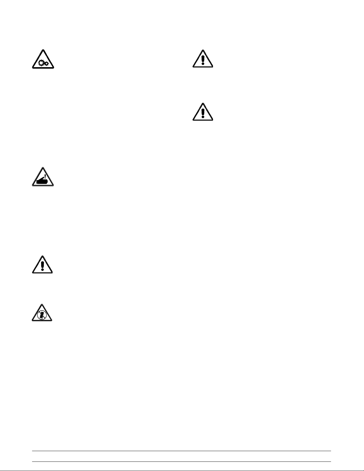
Section 4 Operator Parts Identification
Model 60
Item Description Part No.
1 Cover A.- Hopper- Std. X38458- SER
2 Tube- Feed - 1/4 Hole 015176- 5
3 Pan- Drip 19- 1/2 Long 035034
4 Shield- Splash- Wire 13- 11/16 L 046177
5 Tray- Drip 14.8 046275
6 Panel- Rear w/Louvers 026980- SP
7 Louver- Side 013631
8 Panel A.- Side R X48286
9 Panel A.- Side L X48285
Models 60 & 62 Operator Parts Identification
Item Description Part No.
10 Stud- Nose Cone 5/16- 18 011390
11 Panel - Side Upper 042317
12 Panel A. - Front X46634
13 Pedal A. - Foot X48826
14 Caster- Swv 5/8 Stem 4” Wheel 018794
15 Screw- 1/4- 20 x 3/8 Rhm- Stnls 011694
16 Caster- 4” Swv 5/8 Stem w/Brake 034081
17 Adaptor A.- Caster X18915
130507
7
Page 12
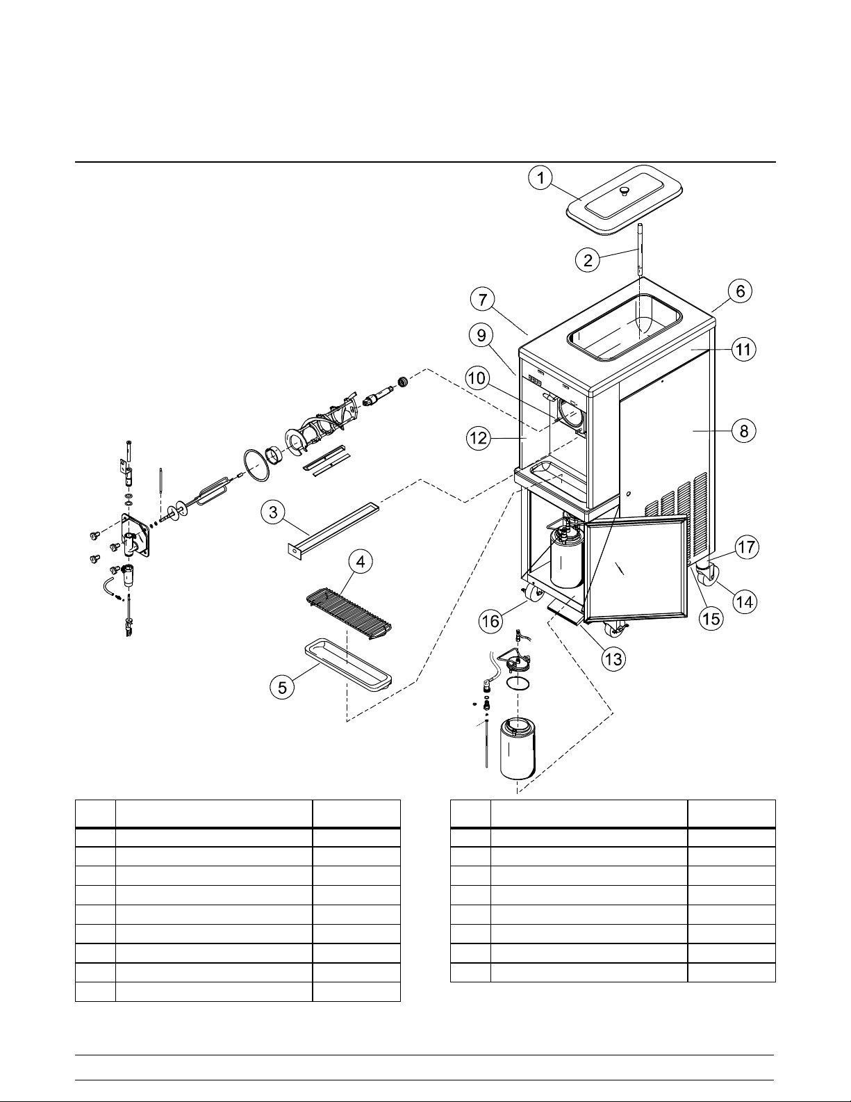
Model 62
Item Description Part No.
1 Cover A.- Hopper- Std. X38458- SER
*1a Knob- Mix Cover 025429
2 Feed Tube 015176- 5
3 Pan- Drip 19- 1/2 Long 035034
4 Shield- Splash 022765
5 Tray- Drip 16- 7/8 L x 5 - 1/8 020157
6 Panel- Rear 039021
7 Louver- Side 013631
Item Description Part No.
8 Panel- Side- Right 050024
Panel A.- Side Left
9
Panel- Side Upper
10 Stud - Nose Cone 5/16- 18 x
3/8- 1
11 Skirt- Air Flow 049069
12 Panel A. - Front X49996
13 Leg-4”SSw/O-ring 013458
*Not Shown
8
Models 60 & 62Operator Parts Identification
X50023
042317
011390
Page 13
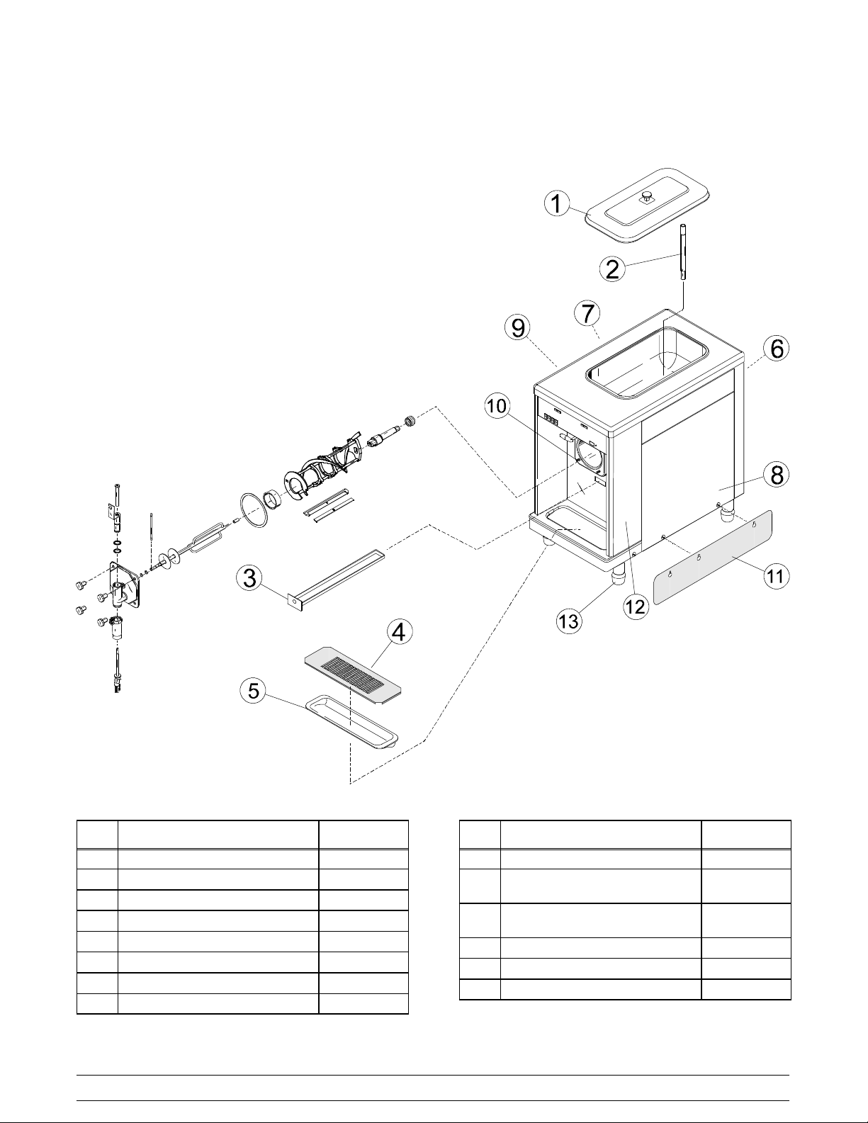
Beater Assembly
Item Description Part No.
1 Seal- Drift Shaft 032560
2 Drive Shaft 035527
3 Beater Assembly X46233
4 Front Bearing 013116
5 Door Gasket 016672
6 Bearing Guide 014496
7 Torque Shaft Assembly X17381
8 Torque Arm 014500
9 O- Ring - Torque Shaft 018550
10 Spinner Bearing 017032
11 Draw Valve Assembly X46671
Models 60 & 62 Operator Parts Identification
Item Description Part No.
12 O- Ring- Draw Valve 020571
13 Stud Nut 021508
14 Tube- Vinyl (Bulk Item #R30314) 020940
15 Fitting- QD Male Insert (M60 only) 036296
16 O- Ring (M 60 Only) 016272
17 Freezer Door Assembly X17373
18 Spinner Housing 017269
19 Spinner Blade Assembly X35570
20 Scraper Blade 046237
21 Clip- Scraper Blade 046238
*22 Female Fitting (M 60 Only) 036295
*Not Shown
090512
9
Page 14
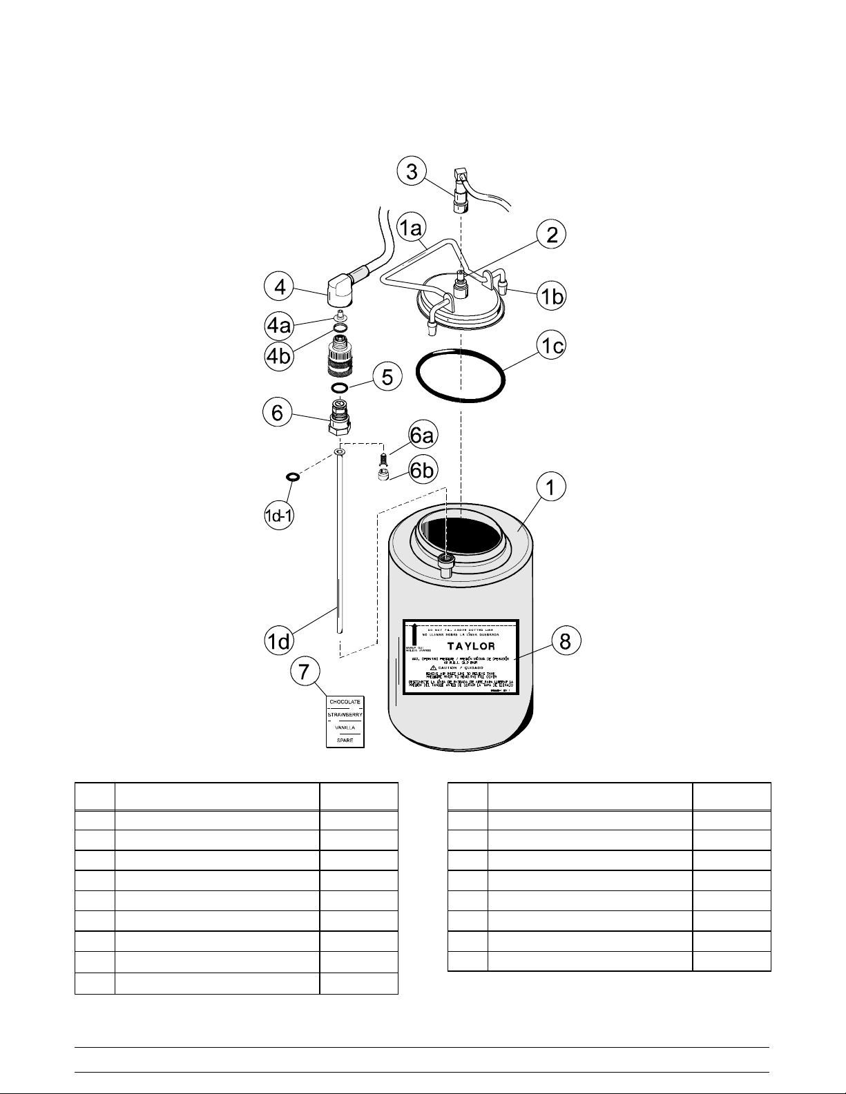
Syrup Tank
Item Description Part No.
1 Tank-Syr-4Qt. 045533
1a Cover- Tank 8 Qt. w/Inlet Ftg. 035759- 1
1b Tip- Nylon- White Translucent 042747
1c O- Ring- 3.437 ID x .275 W 016037
1d Tube- Dip- 4 Qt. Syr. Tank 015441- 7
1d1 O- Ring - .291 ID x .080 W 018550
2 Plug- Q.D. CO2 1/8 MP 021077
3
Socket- Q.D. CO2 90_ 1/4 Barb
4
Socket- Q.D. Liq.- 90_ 1/4 Barb
021524
021026
Item Description Part No.
*4a Restrictor- Syrup 025816
4b Gasket- Rubber 023551
5 O- Ring- 5/8 OD x .103 W 016030
6 Plug-Q.D.Liq.3/4-18FP 021081
6a Valve A.- Q.D . P lug 021081 - 2
6b Insert 021081- 1
7 Decal- Set 4 Syrup Flavor 021523
8 Decal- Syrup Tank Instruction 045533 - 1
*Not used on chocolate
10
Models 60 & 62Operator Parts Identification
Page 15
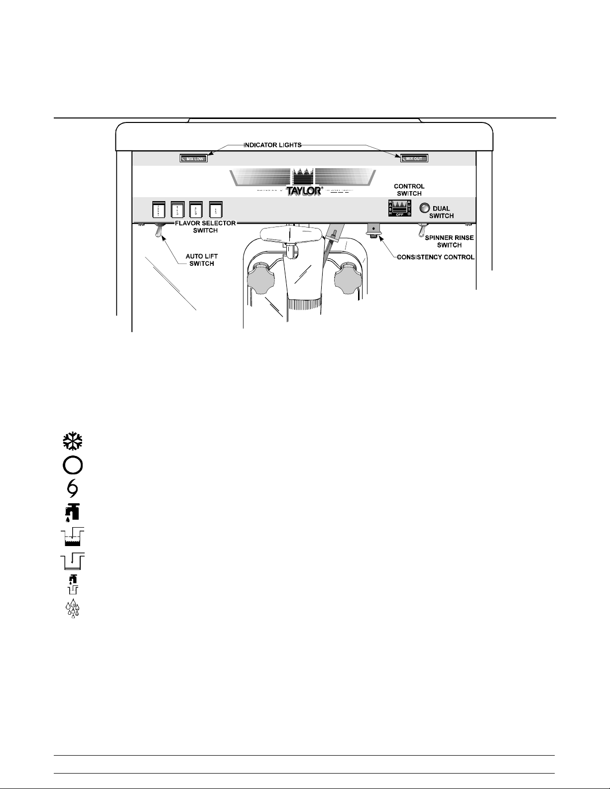
Section 5 Important: To the Operator
To better communicate in the International arena, the
words on many of our operator switches and buttons
have symbols to indicate their functions. Your Taylor
equipment is designed with these International
symbols.
The following chart identifies the symbol definitions
used on the operator switches:
= The “ON/AUTO” button.
= The “OFF” button.
= The “MIX” button.
= The “WASH” button.
= The “MIX LOW” button.
= The “MIX OUT” button.
= The “FILL” button.
= The “RINSE” button.
Control Switch
The center position is “OFF”. The left position is
“WASH”, which activates the beater motor only. The
right position is “AUTO”. It activates the beater motor
and the refrigeration system. To activate the
refrigeration system, raise the draw arm momentarily.
Dial Light
A red dial light is located on the right side of the control
switch. When the control switch is in the “AUTO”
position, this light will come on, indicating that the
refrigeration system is operable.
Indicator Light (“Mix Low”)
The mix low indicator light is located on the front of the
machine directly above the flavor selector switch.
When the light flashes, it indicates that the mix hopper
has a low supply of mix and should be refilled as soon
as possible. If mix is not added, a starved freezing
cylinder will cause damage to the beater, blades, and
drive shaft.
Indicator Light (“Mix Out”)
A mix out indicating light is located on the front of the
machine directly above the control switch. When the
light is on, the machine will shut down to prevent a
starved freezing cylinder.
Models 60 & 62 Important: To the Operator
11
Page 16
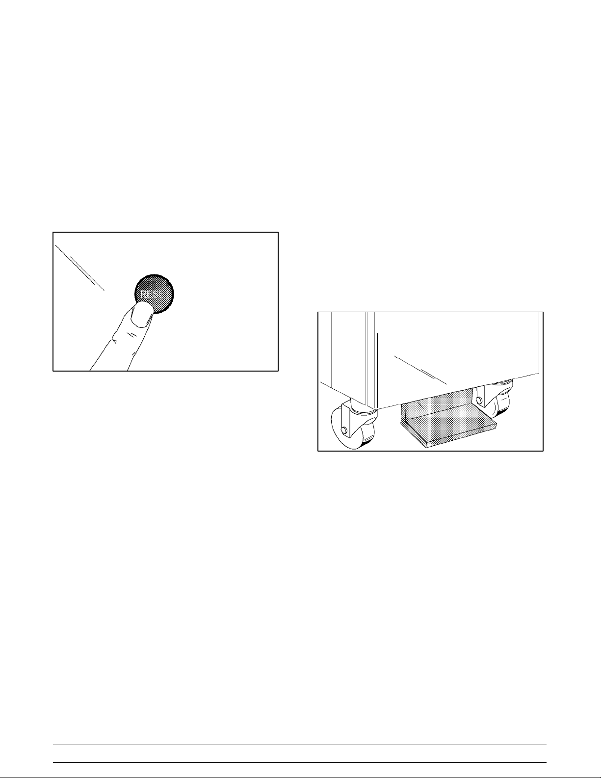
Reset Mechanism
Auto Lift Switch (Model 60 Only)*
The reset protects the beater motor from an overload
condition. If an overload occurs, the reset mechanism
will trip. To properly reset the freezer, set the control
switch to “OFF”. Lift up the right upper side panel and
press the reset button firmly. Turn the control switch to
“WASH” and observe the freezer’s performance.
Return the control switch to the “AUTO” position to
resume normal operation.
If the reset mechanism should trip again, contact your
authorized Taylor Distributor to resolve the problem.
Figure 1
The auto lift switch is located below the flavor selector
switch. To draw product, the auto lift switch may be
used. Press the switch. Just before the desired level
in the cup is reached, release the switch. The draw arm
will lower the draw valve and the product will stop
flowing.
Foot Pedal (Model 60 Only)
The foot pedal is located on the lower front of the
machine. To draw product from the Model 60, the foot
pedal may be used. Press the foot pedal. Just before
the desired level in the cup is reached, release the foot
pedal. The draw arm will lower the draw valve and the
product will stop flowing.
Consistency Control*
The viscosity (thickness) of the shake is controlled by
a sensing device called the consistency control. The
consistency control switch is located below the control
switch. To achieve a thicker shake, turn the knob
clockwise and counterclockwise to achieve a thinner
shake consistency.
Allow the refrigeration system to cycle on and off two
or three times before an accurate consistency can be
evaluated.
Spinner Rinse Switch*
The spinner rinse switch is located next to the
consistency control knob. To clean the spinner housing
from syrup residue:
1. Place the control switch in the “AUTO” position.
2. Hold a cup under the spinner housing.
3. Press the spinner rinse switch. Water will flow
until the switch is released.
4. Release the switch when the housing has been
thoroughly rinsed.
Figure 2
Flavor Selector Switch*
The flavor selector switch consists of four flavor
buttons. The left button controls the No. 1 tank and its
lines. The second button from the left controls the No.
2 tank and its lines. The third button from the left
controls the No. 3 tank and its lines. The right selector
button (“Van”) is the “OFF” button and may be used to
dispense the unflavored product as a vanilla shake.
*See illustration, page 11.
12
Models 60 & 62Important: To the Operator
Page 17

Section 6 Operating Procedures
The Models 60 and 62 have one, 7 quart (6.6 liter)
freezing cylinder. These totally automatic freezers
offer four separate flavors. Each flavor is blended and
ejected from the same spout. (Use only single strength
syrup that is free of pulp and seeds.)
We begin our instructions at the point where we enter
the store in the morning and find the parts
disassembled and laid out to air dry from the previous
night’s brush cleaning.
These opening procedures will show you how to
assemble these parts into the freezer, sanitize them,
and prime the freezer with fresh mix in preparation to
serve your first shake.
Figure 3
groove until it snaps into place. DO NOT lubricate the
hex end of the drive shaft. Fill the inside portion of the
seal with 1/4” more lubricant. Lubricate the flat side of
the seal that comes in contact with the bearing.
Note: Make sure seal is not installed inside- out. The
ridge that protrudes in the center of the seal should be
on the outside.
Figure 4
Insert the drive shaft into the freezing cylinder, hex end
first, and into the rear shell bearing until the seal fits
securely over the rear shell bearing. Be certain the
drive shaft fits into the drive coupling without binding.
If you are disassembling the machine for the first time
or need information to get to this starting point in our
instructions, turn to page 25 “Disassembly”, and start
there.
Assembly
Note: When lubricating parts, use an approved food
grade lubricant (example: Taylor Lube).
Figure 5
MAKESURE THE CONTROL SWITCH IS IN
THE “OFF” POSITION.
Step 1
Install the drive shaft. Lubricate the groove and shaft
portion that comes in contact with the bearing on the
beater drive shaft. Slide the seal over the shaft and the
Models 60 & 62 Operating Procedures
Step 2
Install the beater assembly. First check scraper blades
for any nicks or signs of wear. If any nicks are present
or if the blade is worn, replace both blades.
Note: Both scraper blades should be replaced every
three months.
13
Page 18

If the blades are in good condition, assemble the blade
and the clip. Place the rear scraper blade over the two
rear holding pins (knife edge to the outside).
Figure 6
Holding the rear blade on the beater, slide it halfway
into the freezing cylinder. Install the front scraper blade
and the scraper blade clip over the front holding pins.
Slide the beater assembly the rest of the way into the
freezing cylinder.
Step 3
Install the torque rotor assembly. Assemble the torque
rotor by sliding the two o- rings on the front of the shaft
and lubricate them thoroughly to prevent leaking.
Place the white plastic guide bearing on the rear of the
rotor shaft. DO NOT lubricate the plastic guide bearing
Figure 9
Insert the torque rotor, plastic guide bearing end first,
making sure that it fits into the hole in the beater drive
shaft. Rotate it several times to check for proper
positioning.
Figure 7
Make sure the beater assembly is in position over the
drive shaft. Turn the beater slightly to be certain that
the beater assembly is properly seated.
Figure 8
14
Figure 10
Models 60 & 62Operating Procedures
Page 19

Step 4
Install the draw valve. Lubricate the plastic spinner
bearing. Insert the plastic spinner bearing into the top
of the draw valve.
Figure 11
Slide the two o- rings onto the draw valve and lubricate
the draw valve.
Lubricate the inside of the door spout, top and bottom.
Insert the draw valve into the freezer door from the top.
It will be necessary to rotate the draw valve to the right
when assembling the door to the freezer.
Figure 13
Step 5
Install the freezer door. Place the large rubber gasket
into the groove on the back side of the freezer door. DO
NOT lubricate the gasket.
Figure 12
Models 60 & 62 Operating Procedures
15
Figure 14
Page 20

Slide the white plastic front bearing onto the bearing
hub, making certain that the flanged end of the bearing
sleeve is resting against the freezer door. DO NOT
lubricate the front bearing.
Figure 15
Step 6
Install the drip pan. Slide the drip pan into the hole in
the front panel.
Figure 17
Step 7
Install the spinner housing. Snap the plastic spinner
housing onto the bottom of the door spout.
Assemble the door to the freezer by putting the torque
rotor shaft into the center hole of the freezer door.
Position the door on the four studs on the front of the
freezing cylinder.
Install the four handscrews onto the door and tighten
them equally in a criss- cross pattern.
Figure 16
Figure 18
Lubricate the spinner blade shaft, and insert the
spinner blade from the bottom into the center of the
draw valve.
Figure 19
16
Models 60 & 62Operating Procedures
Page 21

Locate the spinner coupling and slip it over the slotted
end of the spinner blade shaft. Raise the slip collar on
the coupling and turn the shaft from the bottom until the
spinner coupling slips down into its locking position.
Figure 20
Rotate the draw valve to the left, and center it in
position on the draw arm. Place the draw arm into the
slotted groove of the draw valve bracket.
Figure 22
Check the torque arm by moving it back and forth to be
sure it moves freely and easily.
Figure 21
Step 8
Install the torque arm. Position the torque arm by first
slipping it up through the slot in the operating arm.
Secondly, align the other end down in the hole in the
torque rotor shaft which protrudes from the door.
Figure 23
Step 9
Connect the syrup lines. Connect the syrup lines of the
spinner housing to the quick disconnect fittings on the
front panel.
Figure 24
Models 60 & 62 Operating Procedures
17
Page 22

Step 10
Install the front drip tray and the splash shield.
Figure 25
Sanitizing
Step 3
Pour the sanitizing solution into the mix hopper and
allow it to flow into the freezing cylinder.
Figure 27
While the sanitizing solution is bubbling down into the
freezing cylinder, brush clean the mix hopper. While
cleaning the mix hopper, be sure to brush the mix level
sensing probe on the rear wall of the hopper.
Step 1
Prepare an approved 100 PPM sanitizing solution
(examples: 2- 1/2 gal. [9.5 liters] of Kay- 5R or 2
gal. [7.6 liters] of Stera- SheenR). USE WARM WATER AND FOLLOW THE MANUFACTURER’S
SPECIFICATIONS.
NOTE: BEFORE HANDLING SANITIZED
PARTS, SANITIZE YOUR HANDS!
Step 2
Lay the feed tube in the bottom of the mix hopper.
Figure 28
Brush clean the mix inlet hole and the feed tube.
080701
Figure 26
18
Figure 29
Models 60 & 62Operating Procedures
Page 23

Step 4
Press the far right button on the syrup selector switch
(”VAN”). Place the control switch in t he “WASH”
position. This will allow the solution to agitate in the
freezing cylinder. Allow the solution to agitate for five
minutes.
Figure 30
Step 5
Place an empty pail beneath the spinner housing and
raise the draw arm. Draw off all the sanitizing solution.
When the solution stops flowing from the spinner
housing, lower the draw arm and place the control
switch in the “OFF” position.
Priming
Step 1
Be sure the syrup selector switch is in the “OFF”
position (“Van”).
Figure 32
Step 2
With a pail beneath the spinner housing, raise the draw
arm. Pour two gallons (7.6 liters) of FRESH mix into
the mix hopper and allow it to flow down into the
freezing cylinder. This will force out any sanitizing
solution. When full strength mix is flowing from the
spinner housing, lower the draw arm. Discard the
remaining sanitizing solution.
When the mix has stopped bubbling down into the
freezing cylinder, install the feed tube in the mix inlet
hole. During “AUTO” operation be sure the end of the
feed tube with the hole in it is submerged in the mix.
Figure 31
Step 6
Stand the feed tube in the corner of the mix hopper.
Models 60 & 62 Operating Procedures
19
Figure 33
140717
Page 24

Step 3
Place the control switch in the “AUTO” position.
Figure 34
Step 4
To initiate freeze down, rotate the draw valve to the
right so it is disengaged from the draw arm. Lift the
draw arm momentarily. This will start the freezing
cycle. Lower the draw arm and re- engage the draw
valve. When the unit cycles off, the product is ready to
serve.
Step 5
Fill the mix hopper with mix. As the mix level comes in
contact with the mix sensing probe on the rear wall of
the hopper, the “MIX LOW” light will stop flashing.
Figure 36
Place the mix hopper cover in position.
Figure 35
20
Figure 37
Models 60 & 62Operating Procedures
Page 25

Syrup System
Two main objectives in your opening procedures must
be to:
1. fill the syrup tanks.
2. calibrate the syrup flow.
The syrup system must be checked daily to insure the
high quality shake you desire.
Important: Use only single strength syrup that is free
of pulp and seeds.
Model 60
The syrup tanks are located in the lower front syrup
cabinet. The air lines and syrup lines are color spiral
wrapped. Be sure to match the color wrapped air and
syrup line to the right flavor syrup tank.
Figure 39
Figure 38
Model 62
The syrup tanks should be located within reach of the
syrup lines. The air lines and syrup lines are color spiral
wrapped. Be sure to match the color wrapped air and
syrup line to the right flavor syrup tank. Compressed
airorCO
Step 1
Filling the syrup tanks: Pull back the collar of the
quick disconnect fittings for the air lines. Allow the air
pressure to dissipate from the syrup tanks. Disconnect
the syrup lines.
may be used to propel the syrups.
2
Figure 40
Remove the syrup tank lid by lifting up on the locking
lever. Fill the syrup to the indicating mark on the label.
Important: Do not overfill the tanks.
Figure 41
Install the tank lid. Match the spiral wrapped air and
syrup lines to the syrup tank and connect them
accordingly.
Note: Refer to page 26 for cleaning and sanitizing the
syrup tanks.
Models 60 & 62 Operating Procedures
21
Page 26

Step 2
Calibrating the syrup flow: It is vital that the correct
amount of syrup is incorporated into the mix to obtain
a quality shake. Too much syrup often causes thin
shakes. Too little syrup often causes thick shakes.
To determine the rate of syrup flow, use a calibrating
cup indicating the ounces of liquid. Generally the
proper rate of syrup flow is 1 ounce (29.6 ml.) of syrup
in 6 seconds. Once this rate is set, the correct amount
of syrup will be blended with the shake base regardless
of the size of shake served.
Figure 44
Position the large section of the calibrating cup under
the spinner housing.
Figure 42
Rest the draw arm on top of the draw valve. Place the
control switch in the “WASH” position.
Hold an empty cup under the spinner housing and from
the left, press the first flavor button and purge this
syrup line until pure syrup begins to flow steadily .
Figure 43
Note: It is very important to remove any sanitizing
solution and/or air from the syrup lines for accurate
calibration.
Figure 45
With a timing device, press the first flavor button
catching the syrup in the calibrating cup. When the
timing device reaches 6 seconds, press the far right
button (“Van”) to stop the syrup flow. If the amount of
syrup received is 1 ounce (29.6 ml.), the syrup is
properly calibrated.
When pure syrup is flowing steadily from the spinner
housing, press the far right button (“Van”) to stop the
syrup flow.
070131
22
Figure 46
Models 60 & 62Operating Procedures
Page 27

Step 3
Adjusting the syrup pressure: If the amount of
syrup received is less than 1 ounce (29.6 ml.), the
syrup pressure must be increased. If the amount
received is more than 1 ounce (29.6 ml.), the pressure
must be decreased.
Model 60
Inside the syrup compartment is an air pressure
manifold with individual regulators to control the
amount of pressure to each tank and syrup line. The
left regulator is used for syrup line number one and so
on.
Model 62
To make these pressure adjustments, use the
pressure regulators supplied with your freezer. The left
regulator is used for syrup line number one and so on.
Figure 48
Figure 47
If less than 1 ounce (29.6 ml.) is received, the pressure
must be increased. Loosen the lock nut. Using a
flatblade screwdriver, turn the adjusting screw
CLOCKWISE.
Recheck the syrup calibration. Tighten the lock nut
after the correct calibration is achieved.
If more than 1 ounce (29.6 ml.) of syrup is received, the
pressure must be decreased. Loosen the lock nut and
turn the adjusting screw COUNTERCLOCKWISE to
zero. Remove the air line to the syrup tank to allow the
pressure in the tank to escape. Reconnect the air line.
Adjust the regulator to the new pressure setting and
recheck the syrup calibration. Tighten the lock nut.
Figure 49
Repeat the calibration procedures for each additional
syrup line.
Note: Refer to page 27 for cleaning and sanitizing the
syrup lines.
Drawing Product
Step 1
Prepare to draw product by holding a cup under the
spinner housing. Press a desired flavor selection
button.
Step 2
Model 60
To draw product, push the auto lift toggle switch or
press the foot pedal. This will cause the:
A. Draw arm to lift the draw valve to the open
position.
B. Beater and spinner to start and the solenoid
valve (if flavor is used) to open.
C. A constant amount of flavor is blended into the
product as it flows out of the freezer.
Models 60 & 62 Operating Procedures
23
Page 28

Release the auto lift toggle switch or the foot pedal just
before the desired level in the cup is reached. The
draw arm will lower the draw valve and the product will
stop flowing.
IMPORTANT RECOMMENDATION: The Model 60
incorporates an auto lift system. This system may be
activated by either a hand switch or foot pedal.
Drawing product may also be accomplished by lifting
the draw arm.
Model 62
To draw product, raise the draw handle fully. This will
cause the:
A. Beater and spinner to start and the solenoid
valve (if flavor is used) to open.
B. A constant amount of flavor is blended into the
product as it flows out of the freezer.
Lower the draw handle and the product will stop
flowing.
Closing Procedures
To disassemble this machine, the following items will
be needed:
S Two cleaning pails
S Sanitized stainless steel rerun can with lid
S Necessary brushes (provided with freezer)
S Cleaner/Sanitizer
S Single service towels
Step 4
Remove the mix hopper cover and feed tube from the
mix hopper. Take these parts to the sink for cleaning.
Step 5
If local health codes permit the use of rerun,place
a sanitized, NSF approved stainless steel rerun
container beneath the spinner housing and place the
control switch in the “WASH” position.
Model 60: Drain all the product remaining in the
freezing cylinder and mix hopper by pressing the auto
lift toggle switch or pressing the foot pedal. When the
flow of product stops, release the auto lift toggle switch
or foot pedal. Place the control switch in the “OFF”
position.
Model 62: Drain all the product remaining in the
freezing cylinder and mix hopper by raising the draw
handle. When the flow of product stops, release the
draw handle. Place the control switch in the “OFF”
position.
Place a sanitized lid on the rerun container and place
it in the walk- in cooler. (Note: For additional
information regarding the proper use of rerun, see item
5 on page 29.)
Note: If local health codes DO NOT permit the use
of rerun, the product must be discarded. Follow the
instructions in Step 5, except drain the product into a
pail and properly discard the mix.
ALWAYS FOLLOW LOCAL HEALTH CODES.
Draining Product From The
Freezing Cylinder
Step 1
Place the control switch in the “OFF” position as far
ahead of cleaning time as possible to allow the frozen
product to soften for easier cleaning.
Step 2
Press the far right button on selector switch assembly
(“Van”).
Step 3
Remove the spinner blade by lifting the slip collar on
the spinner coupling. Pull the spinner blade out from
the bottom of the spinner housing.
140717
Rinsing
Step 1
Pour two gallons (7.6 liters) of cool, clean water into
the mix hopper. With the brushes provided, brush
clean the mix hopper, mix inlet hole, and mix level
sensing probe.
Step 2
Press the far right switch on the selector switch
assembly (“Van”). Place the control switch in the
“WASH” position.
24
Models 60 & 62Operating Procedures
Page 29

Step 3
Step 6
Model 60
With an empty pail under the spinner housing, push the
auto lift toggle switch or press the foot pedal and drain
off all the rinse water. When the flow of rinse water
stops, release the auto lift toggle switch or foot pedal.
Model 62
With an empty pail under the spinner housing, raise the
draw handle and drain off all the rinse water. When the
flow of rinse water stops, release the draw handle.
Place the control switch in the “OFF” position.
Step 4
Repeat this procedure until the rinse water being
discharged is clear.
Cleaning
Model 60
Press the auto lift toggle switch or press the foot pedal
and drain out all the solution. When the solution stops
flowing from the spinner housing, release the auto lift
toggle switch or foot pedal.
Model 62
Raise the draw handle and drain out all the solution.
When the solution stops flowing from the spinner
housing, release the draw handle.
Place the control switch in the “OFF” position. Take the
pail to the sink and discard the solution.
Disassembly
MAKE SURE THAT ALL SWITCHES ARE
IN THE “OFF” POSITION BEFORE DISASSEMBLY.
Step 1
Remove the torque arm. Separate the spinner housing
from the freezer door. Note: Pull the spinner housing
towards you.
Step 1
Prepare an approved 100 PPM cleaning solution
(examples: 2- 1/2 gal. [9.5 liters] of Kay- 5R or 2
gal. [7.6 liters] of Stera- SheenR). USE WARM WATER AND FOLLOW THE MANUFACTURER’S
SPECIFICATIONS.
Step 2
Pour the cleaning solution into the hopper and allow it
to flow into the freezing cylinder.
Step 3
While the solution is flowing into the freezing cylinder,
brush clean the mix hopper, mix inlet hole, and the mix
level sensing probe.
Step 4
Place the control switch in the “WASH” position. This
will cause the cleaning solution in the freezing cylinder
to be agitated.
Step 5
Place an empty pail beneath the spinner housing. Be
sure the far right button (“Van”) on the selector switch
assembly is pressed.
Step 2
Disengage the draw arm from the draw valve and
rotate the draw valve to the right.
Step 3
Remove the freezer door, door gasket, front bearing,
torque rotor assembly, beater, scraper blades, and
drive shaft and seal from the freezing cylinder. Note:
When removing the door, take extreme care to
separate the torque rotor shaft from the door. Costly
damage will result if these parts are dropped during
disassembly. Take all these parts to the sink for
cleaning.
If the guide bearing is not on the end of the torque rotor
shaft, it is still lodged in the beater drive shaft. To
remove, insert the torque arm into the side hole of the
drive shaft and push the bearing forward.
Step 4
Take the front drip tray and the splash shield to the sink
for cleaning.
Step 5
Remove the rear drip pan from the front panel. Note:
If the drip pan is filled with an excessive amount of mix,
it is an indication that the drive shaft seal should be
replaced or that it was improperly lubricated.
080701
Models 60 & 62 Operating Procedures
25
Page 30

Brush Cleaning
Step 1
Prepare a sink with an approved cleaning solution (examples: Kay-5R or Stera- SheenR). USE WARM
WATER ACCORDING TO THE MANUFACTURER’S
SPECIFICATIONS. If an approved cleaner other than
Kay- 5r or Stera- SheenR is used, dilute according
to label instructions.
IMPORTANT: Follow label directions. Too STRONG
of a solution can cause parts damage; too MILD of a
solution will not provide adequate cleaning. Make sure
all brushes provided with the freezer are available for
brush cleaning.
Step 2
Remove the draw valve from the freezer door. Remove
the spinner bearing from the draw valve. Remove all
o- rings from the draw valve and torque rotor
assembly. Remove the seal from the drive shaft.
Remove the feed tube from the hopper.
Note: To remove o- rings, use a single service towel
to grasp the o- ring. Apply pressure in an upward
direction until the o- ring pops out of its groove. With
the other hand, push the top of the o- ring forward, and
it will roll out of the groove and can be easily removed.
If there is more than one o- ring to be removed, always
remove the rear o- ring first. This will allow the o- ring
to slide over the forward rings without falling into the
open grooves.
Step 3
Thoroughly brush clean all disassembled parts in the
cleaning solution, making sure all lubricant and mix film
is removed. Take particular care to brush clean the
draw valve core and the holes in the freezer door.
Figure 50
Step 6
Wipe clean all exterior surfaces of the freezer.
Sanitizing Syrup System
Two main objectives in your closing procedures must
be to:
1. Discard all syrup at least once a week, and
2. Flush the syrup lines at least once a week.
This must be done on a regular basis to keep a
build- up of old syrup from clogging the lines and to
break the bacteria chain which develops in the tanks
and lines.
IMPORTANT: Calibrating the syrup flow must be done
every morning, especially after flushing the syrup
lines. Use only single strength syrup that is free of pulp
and seeds.
Step 1
Sanitizing syrup tanks: Pull back on the collar of the
quick disconnect fitting of the air line. Allow the air
pressure to dissipate from the syrup tank. Disconnect
the syrup line.
Step 4
Place the cleaned parts on a clean, dry surface to air
dry overnight.
Step 5
Take a small amount of cleaning solution to the freezer.
With the black bristle brush, brush clean the rear shell
bearing at the back of the freezing cylinder.
080701
Remove the syrup tank from its compartment.
Remove the syrup tank lid by lifting up on the locking
lever, and discard the remaining syrup.
Rinse the syrup tank with clean, warm water.
Prepare 1/2 gallon (1.9 liters) of the recommended
sanitizing solution with warm water in the syrup tank.
Brush clean the inside and outside of the tank.
26
Models 60 & 62Operating Procedures
Page 31
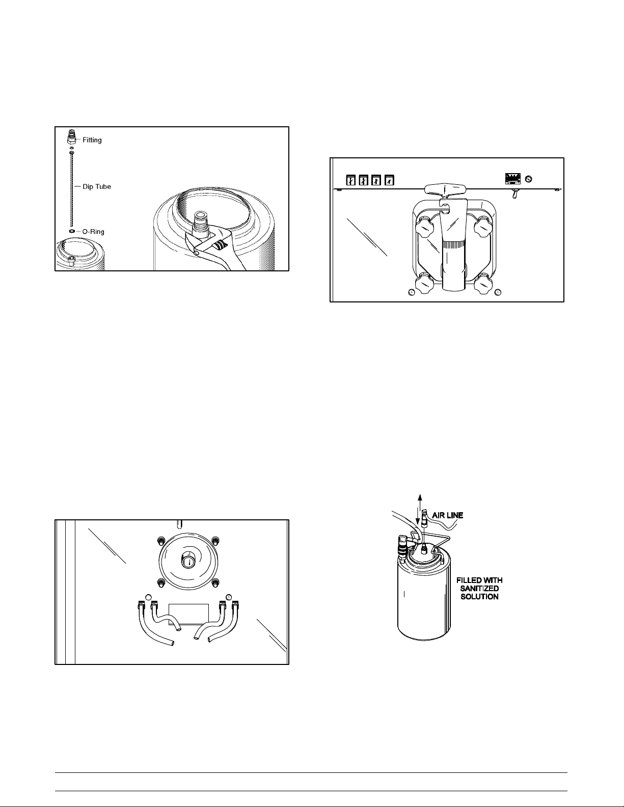
Using an adjustable wrench, remove the syrup line
fitting from each tank. Remove the dip tube and o- ring
from the syrup tank.
Figure 51
Thoroughly brush clean the dip tube, syrup line fitting,
and o- ring, using the sanitizing solution. Reassemble
dip tube, o- ring, and syrup line fitting.
Step 4
Install the freezer door and the draw valve on the
freezer. Raise the draw arm and rest the arm on the top
of the draw valve.
Figure 53
Pour out all the sanitizing solution and place the tank
in an upside- down position on a clean, dry surface to
air dry.
Repeat this procedure for all syrup tanks.
Step 2
Sanitizing syrup lines: Prepare one gallon (3.8
liters) of the recommended sanitizing solution with
warm water in the spare syrup tank. Replace and lock
the tank lid into position. Place this tank in the syrup
compartment.
Step 3
Remove the syrup lines from the spinner housing.
Wash and sanitize the spinner housing.
Step 5
Press the far right button on the selector switch
assembly (“Van”), and place the control switch in
“WASH”. This will partially close the electrical circuit so
the syrup lines can be flushed by merely pressing the
flavor buttons.
Step 6
Connect the No. 1 air pressure line and syrup line to
the tank filled with sanitizing solution.
Figure 52
Models 60 & 62 Operating Procedures
27
Figure 54
Page 32

Step 7
Place an empty pail beneath the ends of the syrup
lines. Press the left flavor button and flush the No. 1
syrup line until the solution runs clear. Press the far
right button (“Van”) to stop the flow of sanitizing
solution.
Figure 55
Note: This procedure will thoroughly clean the ends
of the syrup lines that attach to the spinner housing to
prevent bacteria build- up.
Step 8
Disconnect the No. 1 air and syrup lines from the tank
now partially filled with sanitizer.
Step 9
Connect the No. 2 air and syrup lines to the tank and
repeat the procedure by pressing the second flavor
button from the left, and so on, until all three syrup lines
have been cleaned and sanitized.
Step 10
The fourth syrup line is for the spinner rinse. To
effectively sanitize the end of this syrup line, use a
small amount of fresh sanitizer on a brush and brush
clean the end of the fourth syrup line. Press the spinner
rinse button to further flush this rinse line.
Repeat this step for each syrup line.
Step 11
Disconnect the air line and syrup line from the tank with
the remaining sanitizer in it. Remove the tank lid and
pour out all the remaining sanitizing solution. Place the
tank in an upside down position on a clean, dry surface
to air dry.
Step 12
Attach the syrup lines to the spinner housing.
Step 13
Remove the freezer door and the draw valve.
28
Models 60 & 62Operating Procedures
Page 33

Section 7 Important: Operator Checklist
During Cleaning and Sanitizing:
Cleaning and sanitizing schedules are governed
by federal, state, or local regulatory agencies,
and must be followed accordingly. If the unit
has a “Standby mode”, it must not be used in
lieu of proper cleaning and sanitizing
procedures and frequencies set forth by the
ruling health authority. The following check
points should be stressed during the cleaning
and sanitizing operations.
CLEANING AND SANITIZING MUST BE
PERFORMED DAILY.
ALWAYS FOLLOW LOCAL HEALTH CODES.
Troubleshooting Bacterial Count:
j 6. On a designated day of the week, run the mix as
low as feasible and discard after closing. This
will break the rerun cycle and reduce the
possibility of high bacteria and coliform counts.
j 7. Properly prepare the cleaning and sanitizing
solutions. Read and follow label directions
carefully. Too STRONG of a solution may
damage the parts and too WEAK of a solution
will not do an adequate job of cleaning or
sanitizing.
j 8. Empty all syrup from the tanks and discard at
least once a week.
j 9. Thoroughly clean and sanitize the syrup lines at
least once a week.
j 10. T emperature of mix in mix hopper and walk- in
cooler should be below 40_F. ( 4 . 4_C.).
j 1. Thoroughly clean and sanitize machine
regularly, including complete disassembly and
brush cleaning.
j 2. Use all brushes supplied for thorough cleaning.
The brushes are specially designed to reach all
mix passageways.
j 3. Use the white bristle brush to clean the mix inlet
hole which extends from the mix hopper down
to the rear of the freezing cylinder.
j 4. Use the black bristle brush to thoroughly clean
the rear shell bearing located at the rear of the
freezing cylinder. Be sure to have a generous
amount of cleaning solution on the brush.
j 5. IF LOCAL HEALTH CODES PERMIT THE
USE OF RERUN make sure the mix rerun is
stored in a sanitized, covered stainless steel
container and used the following day. DO NOT
prime the machine with rerun. When using
rerun, skim off foam and discard; then mix it with
fresh mix in a ratio of 50/50 during the day’s
operation.
Regular Maintenance Checks:
j 1. Rotate scraper blades to allow both sides of the
knife edge to wear evenly. This will contribute to
self- sharpening and help maintain fast, efficient
freezing.
j 2. Replace scraper blades that are nicked,
damaged or worn.
j 3. Before installing beater, be certain that scraper
blades are properly attached over the beater
pins
j 4. Check rear shell bearing for signs of wear
(excessive mix leakage in rear drip pan) and be
certain it is properly cleaned.
j 5. Using a screwdriver and cloth towel, keep the
female hex drive socket clean and free of
lubricant and mix deposits.
120109
Models 60 & 62 Important: Operator Checklist
29
Page 34

j 6. Dispose of o- rings and seals if they are worn,
torn, or fit too loosely , and replace with new
ones.
j 7. Follow all lubricating procedures as outlined in
“Assembly”.
Winter Storage
If the place of business is to be closed during the winter
months, it is important to protect the freezer by
following certain precautions, particularly if the
building is to be left unheated and subject to freezing
conditions.
j 8. If your machine is air cooled, check the
condenser for accumulation of dirt and lint. Dirty
condensers will reduce the efficiency and
capacity of the machine. Condensers should be
cleaned monthly with a soft brush. Never use
screwdrivers or other metal probes to clean
between the fins.
Note: For machines equipped with an air filter,
it will be necessary to vacuum clean the filters
on a monthly schedule.
j 9. On water cooled units, check the water lines for
kinks or leaks. Kinks can occur when the
machine is moved back and forth for cleaning or
maintenance purposes. Deteriorated or
cracked water lines should be replaced only by
an authorized Taylor mechanic.
Disconnect the freezer from the main power source to
prevent possible electrical damage.
On water cooled freezers, disconnect the water
supply. Relieve pressure on spring in water valve. Use
air pressure on the outlet side to blow out any water
remaining in the condenser. This is extremely
important. Failure to follow this procedure may cause
severe and costly damage to the refrigeration system.
Your local Taylor Distributor can perform this service
for you.
Wrap detachable parts of the freezer such as beater,
blades, drive shaft, and freezer door, and place in a
protected dry place. Rubber trim parts and gaskets
can be protected by wrapping with moisture- proof
paper. All parts should be thoroughly cleaned of dried
mix or lubrication accumulations which attract mice
and other vermin.
080626
30
Models 60 & 62Important: Operator Checklist
Page 35

Section 8 Troubleshooting Guide
PROBLEM PROBABLE CAUSE REMEDY PAG E
REF.
1. No product being
dispensed.
a. Inadequate mix in mix
hopper.
b. Control switch in the
“OFF” position.
c. Freeze- up in mix inlet
tube.
d. Beater motor out on reset. d. Reset freezer. 12
e. Wrong beater rotation. e. Call service technician to
f. Beater motor will not
activate with draw arm in
the raised position.
g. Frozen clumps of product
blocking flow of mix to
freezing cylinder.
h. Draw arm not engaged in
draw valve.
a. Fill mix hopper. 20
b. Place control switch in the
“AUTO” position.
c. Call service technician to
adjust mix hopper
termperature.
correct rotation. Should
rotate clockwise from the
operator’s end.
f. An electrical problem
requiring a service call.
g. Improper handling of
rerun. Rerun must be
thawed completely and
foam must be skimmed
off. Always mix 50% fresh
mix with 50% rerun.
h. Center draw valve on
draw arm.
20
---
---
---
29
17
2. Product too stiff. a. Improper lubrication of
torque rotor o- rings.
b. Improper consistency
control adjustment.
c. Torque rotor binding. c. Before installing the
d. Not enough syrup being
blended with product.
e. Torque arm not installed. e. Install torque arm. 17
Models 60 & 62 Troubleshooting Guide
31
a. Lubricate o- rings properly. 14
b. Product, with no syrup
blended, should be
dispensed at 26 to 28_F
(- 3.3 to - 2.2_C).
torque arm, check to see
if torque rotor can be
rotated freely without
binding.
d. Calibrate the syrup
system. Syrup delivery
should be 1 oz. (29.6 ml.)
in 6 seconds.
12
14
22
070131
Page 36

PROBLEM PROBABLE CAUSE REMEDY PAG E
REF.
3. Product too soft. a. Improper consistency
control adjustment.
b. Torque rotor binding. b. Before installing the
c. Improper lubrication of
torque rotor o- rings.
d. Lubrication of torque rotor
guide bearing.
e. Too much syrup being
blended with product.
f. Bad scraper blades. f. Replace scraper blades. 35
g. Dirty condenser. g. Brush condenser clean
4. Large pressure
adjustments are
necessary to receive 1 oz.
(29.6 ml.) in 6 seconds.
a. Hardened syrup in syrup
line.
a. Product, with no syrup
blended, should be
dispensed at 26 to 28_F
(- 3.3 to - 2.2_C).
torque arm, check to see
if the torque rotor can be
rotated freely without
binding.
c. Lubricate o- rings properly. 14
d. Do not lubricate guide
bearing.
e. Calibrate the syrup
system. Syrup delivery
should be 1 oz. (29.6 ml.)
in 6 seconds.
every 30 days.
a. Sanitize syrup lines once
a week.
12
14
14
22
30
26
b. Syrup line and air line not
matched properly to syrup
tank.
5. Mix hopper too warm. a. Product too warm when
placed in hopper.
b. Control switch in the
“OFF” position.
c. Needs temperature
adjustment.
6. Mix hopper too cold. a. Needs temperature
adjustment.
b. Match syrup and air lines
to syrup tank.
a. Check temperature in
storage cooler.
b. Place in “AUTO” position. 20
c. Call service technician to
make adjustment.
a. Call service technician to
make adjustment.
21
29
---
---
070131
32
Models 60 & 62Troubleshooting Guide
Page 37

PROBLEM PROBABLE CAUSE REMEDY PAG E
REF.
7. Machine short cycling
(rapid on and off cycles).
8. Freezing cylinder walls
scored.
9. Drive shaft stuck in gear
box coupling.
a. Dirty air cooled
condenser.
b. Inadequate water supply
on water cooled unit.
c. Defective condenser fan. c. Call service technician to
d. No air space surrounding
machine.
a. Gear box out of alignment. a. Call service technician to
b. Bent beater assembly. b. Call service technician to
c. Missing front bearing. c. Replace front bearing. ---
d. Broken beater pins. d. Call service technician to
a. Lubrication on hex end of
shaft.
b. Rounded corners of hex
end of drive shaft.
c. Rounded corners of
coupling on gear box.
a. Brush clean every 30
days.
b. Check water supply. 2
repair or replace.
d. Maintain specified air
clearance.
realign gear box.
repair or replace.
repair or replace.
a. Call service techician for
removal.
b. Replace defective drive
shaft.
c. Call service technician to
replace gear box.
30
---
---
---
---
---
---
---
2
10. Excessive leakage of mix
into rear drip pan.
1 1. Machine will not operate
when control switch is in
“AUTO”.
a. Worn or missing seal on
drive shaft.
b. Inadequate lubrication of
drive shaft.
c. Bad rear shell bearing. c. Call service technician to
d. Drive shaft and beater
working forward.
a. Draw arm not raised. a. Raise draw arm
b. Beater motor out on reset. b. Reset freezer. 12
c. Circuit breaker off. c. Turn breaker on. ---
d. Water turned off (water
cooled units).
e. Power cord unplugged. e. Plug cord into wall
a. Replace every 3 months. 35
b. Follow lubrication
procedures in “Assembly”.
replace rear shell bearing.
d. Call service technician. ---
momentarily to activate
system.
d. Re- establish water
supply.
receptacle.
13
---
20
---
---
011213
Models 60 & 62 Troubleshooting Guide
33
Page 38

PROBLEM PROBABLE CAUSE REMEDY PAG E
REF.
12. Water continues to flow
through spinner housing.
13. Lift motor continues to
raise draw valve after
draw of product has been
made.
14. Air compressor runs too
often for normal usage.
15. Spinner shaft will not
rotate to blend syrup into
product.
16. Excessive drippage of
product from spinner
housing.
a. Rinse solenoid stuck
open.
a. Micro switch needs
adjustment.
a. Air leak in system. a. Use a soap solution to
a. Flexible cable broken. a. Call service technician to
b. Pin missing in female
quick disconnect.
c. Spinner motor out on
thermal overload.
a. Worn o- rings on draw
valve.
b. Wrong o- rings on draw
valve.
a. Call service technician for
repair.
a. Call service technician for
repair.
locate the leak.
replace cable.
b. Call service technician to
replace disconnect.
c. Inadequate lubrication of
spinner shaft. Lubricate
entire length of shaft.
a. Replace every 3 months. 35
b. Check o- ring size. ---
---
---
---
---
---
16
c. Inadequate lubrication of
spinner shaft.
c. Follow lubrication
procedures in “Assembly”.
16
34
Models 60 & 62Troubleshooting Guide
Page 39

Section 9 Parts Replacement Schedule
PART DESCRIPTION EVERY 3 MONTHS EVERY 6 MONTHS ANNUALLY
Drive Shaft Seal X 1
Scraper Blades Inspect & Replace
if Necessary
Freezer Door Gasket X 1
Front Bearing X 1
Draw Valve O- Rings X 2
Torque Rotor Guide Bearing X 1
Torque Rotor O- Rings X 2
Feed Assembly O- Rings X 2
Double Ended Brush Inspect & Replace
Black Bristle Brush, 1” x 2” Inspect & Replace
White Bristle Brush, 1- 1/2” x 2” Inspect & Replace
Minimum 2
Minimum 1
if Necessary
Minimum 1
if Necessary
Minimum 1
if Necessary
QUANTITIES TO
BE REPLACED
White Bristle Brush, 3” x 7” Inspect & Replace
if Necessary
Tune- Up Kits are available from your Taylor Distributor. Keep your freezer in top condition with the above replacement
parts in a “Tune- Up Kit” for your model of freezer! Ask your Taylor Distributor about the Automatic 3- Month Tune- Up
Kit Mailing Program.
Minimum 1
Models 60 & 62 Parts Replacement Schedule
35
Page 40

Section 10 Limited Warranty on Equipment
TAYLOR COMPANY LIMITED WARRANTY ON FREEZERS
Taylor Company , a division of Carrier Commercial Refrigeration, Inc. (“Taylor”) is pleased to provide this limited
warranty on new Taylor-branded freezer equipment available from Taylor to the market generally (the “Product”)
to the original purchaser only.
LIMITED WARRANTY
Taylor warrants the Product against failure due to defect in materials or workmanship under normal use and
service as follows. All warranty periods begin on the date of original Product installation. If a part fails due to
defect during the applicable warranty period, Taylor, through an authorized Taylor distributor or service agency,
will provide a new or re- manufactured part, at Taylor’s option, to replace the failed defective part at no charge for
the part. Except as otherwise stated herein, these are Taylor’s exclusive obligations under this limited warranty for
a Product failure. This limited warranty is subject to all provisions, conditions, limitations and exclusions listed
below and on the reverse (if any) of this document.
Product
Soft Serve
Frozen Yogurt
Shakes
Smoothies
Frozen Beverage
Batch Desserts
1. If the date of original installation of the Product cannot be verified, then the limited warranty period begins
ninety (90) days from the date of Product manufacture (as indicated by the Product serial number). Proof of
purchase may be required at time of service.
2. This limited warranty is valid only if the Product is installed and all required service work on the Product is
performed by an authorized Taylor distributor or service agency, and only if genuine, new Taylor parts are
used.
3. Installation, use, care, and maintenance must be normal and in accordance with all instructions contained in
the Taylor Operator’s Manual.
Insulated shell assembly Five (5) years
Refrigeration compressor
(except service valve)
Beater motors T wo (2) years
Beater drive gear T wo (2) years
Printed circuit boards and
Softech controls beginning
with serial number H8024200
Parts not otherwise listed in
this table or excluded below
LIMITED WARRANTY CONDITIONS
Part Limited Warranty Period
Five (5) years
Two (2) years
One (1) year
4. Defective parts must be returned to the authorized Taylor distributor or service agency for credit.
5. The use of any refrigerant other than that specified on the Product’s data label will void this limited warranty.
LIMITED WARRANTY EXCEPTIONS
This limited warranty does not
1. Labor or other costs incurred for diagnosing, repairing, removing, installing, shipping, servicing or handling of
defective parts, replacement parts, or new Products.
2. Normal maintenance, cleaning and lubrication as outlined in the T aylor Operator’s Manual, including cleaning
of condensers.
131108
cover:
36
Models 60 & 62Limited Warranty on Equipment
Page 41

3. Replacement of wear items designated as Class “000” parts in the Taylor Operator’s Manual.
4. External hoses, electrical power supplies, and machine grounding.
5. Parts not supplied or designated by Taylor, or damages resulting from their use.
6. Return trips or waiting time required because a service technician is prevented from beginning warranty
service work promptly upon arrival.
7. Failure, damage or repairs due to faulty installation, misapplication, abuse, no or improper servicing,
unauthorized alteration or improper operation or use as indicated in the Taylor Operator’s Manual, including
but not limited to the failure to use proper assembly and cleaning techniques, tools, or approved cleaning
supplies.
8. Failure, damage or repairs due to theft, vandalism, wind, rain, flood, high water, water, lightning, earthquake
or any other natural disaster, fire, corrosive environments, insect or rodent infestation, or other casualty,
accident or condition beyond the reasonable control of Taylor; operation above or below the electrical or
water supply specification of the Product; or components repaired or altered in any way so as, in the
judgment of the Manufacturer, to adversely affect performance, or normal wear or deterioration.
9. Any Product purchased over the Internet.
10. Failure to start due to voltage conditions, blown fuses, open circuit breakers, or damages due to the
inadequacy or interruption of electrical service.
1 1. Electricity or fuel costs, or increases in electricity or fuel costs from any reason whatsoever.
12. Damages resulting from the use of any refrigerant other than that specified on the Product’s data label will
void this limited warranty.
13. Any cost to replace, refill or dispose of refrigerant, including the cost of refrigerant.
14. ANY SPECIAL, INDIRECT OR CONSEQUENTIAL PROPERTY OR COMMERCIAL DAMAGE OF ANY
NATURE WHATSOEVER. Some jurisdictions do not allow the exclusion of incidental or consequential
damages, so this limitation may not apply to you.
This limited warranty gives you specific legal rights, and you may also have other rights which vary from
jurisdiction to jurisdiction.
LIMITA TION OF WARRANTY
THIS LIMITED WARRANTY IS EXCLUSIVE AND IS IN LIEU OF ALL OTHER WARRANTIES, CONDITIONS
AND/OR REMEDIES UNDER THE LAW, INCLUDING ANY IMPLIED WARRANTIES OR CONDITIONS OF
MERCHANTABILITY OR FITNESS FOR A PARTICULAR PURPOSE. THE ORIGINAL OWNER’S SOLE
REMEDY WITH RESPECT TO ANY PRODUCTS SHALL BE REPAIR OR REPLACEMENT OF DEFECTIVE
COMPONENTS UNDER THE TERMS OF THIS LIMITED WARRANTY. ALL RIGHTS TO CONSEQUENTIAL
OR INCIDENTAL DAMAGES (INCLUDING CLAIMS FOR LOST SALES, LOST PROFITS, PRODUCT LOSS,
PROPERTY DAMAGES OR SERVICE EXPENSES) ARE EXPRESSLY EXCLUDED. THE EXPRESS
WARRANTIES MADE IN THIS LIMITED WARRANTY MAY NOT BE ALTERED, ENLARGED, OR CHANGED
BY ANY DISTRIBUTOR, DEALER, OR OTHER PERSON, WHATSOEVER.
LEGAL REMEDIES
The owner must notify Taylor in writing, by certified or registered letter to the following address, of any defect or
complaint with the Product, stating the defect or complaint and a specific request for repair, replacement, or other
correction of the Product under warranty , mailed at least thirty (30) days before pursuing any legal rights or
remedies.
Taylor Company
a division of Carrier Commercial Refrigeration, Inc.
750 N. Blackhawk Blvd.
Rockton, IL 61072, U.S.A.
131108
Models 60 & 62 Limited Warranty on Equipment
37
Page 42

Section 11 Limited Warranty on Parts
TAYLOR COMPANY LIMITED WARRANTY ON TAYLOR GENUINE PARTS
Taylor Company , a division of Carrier Commercial Refrigeration, Inc. (“Taylor”) is pleased to provide this limited
warranty on new Taylor genuine replacement components and parts available from Taylor to the market generally
(the “Parts”) to the original purchaser only.
LIMITED WARRANTY
Taylor warrants the Parts against failure due to defect in materials or workmanship under normal use and service
as follows. All warranty periods begin on the date of original installation of the Part in the Taylor unit. If a Part fails
due to defect during the applicable warranty period, Taylor, through an authorized T aylor distributor or service
agency, will provide a new or re- manufactured Part, at Taylor’s option, to replace the failed defective Part at no
charge for the Part. Except as otherwise stated herein, these are Taylor’s exclusive obligations under this limited
warranty for a Part failure. This limited warranty is subject to all provisions, conditions, limitations and exclusions
listed below and on the reverse (if any) of this document.
Part’s Warranty Class Code or Part
Class 103 Parts¹ Three (3) months
Class 212 Parts² Twelve (12) months
Class 512 Parts Twelve (12) months
Class 000 Parts No warranty
Taylor Part #072454 (Motor- 24VDC *C832/C842*) Four (4) years
LIMITED WARRANTY CONDITIONS
1. If the date of original installation of the Part cannot be otherwise verified, proof of purchase may be required
at time of service.
2. This limited warranty is valid only if the Part is installed and all required service work in connection with the
Part is performed by an authorized Taylor distributor or service agency.
3. The limited warranty applies only to Parts remaining in use by their original owner at their original installation
location in the unit of original installation.
4. Installation, use, care, and maintenance must be normal and in accordance with all instructions contained in
the Taylor Operator’s Manual.
5. Defective Parts must be returned to the authorized T aylor distributor or service agency for credit.
6. This warranty is not intended to shorten the length of any warranty coverage provided pursuant to a separate
Taylor Limited Warranty on freezer or grill equipment.
Limited Warranty Period
7. The use of any refrigerant other than that specified for the unit in which the Part is installed will void this
limited warranty.
1, 2
Except that T aylor Part #032129SER2 (Compressor-Air-230V SERV) and Taylor Part #075506SER1
(Compressor-Air-115V 60HZ) shall have a limited warranty period of twelve (12) months when used in T aylor
freezer equipment and a limited warranty period of two (2) years when used in T aylor grill equipment.
131108
38
Models 60 & 62Limited Warranty on Parts
Page 43

LIMITED WARRANTY EXCEPTIONS
This limited warranty does not
cover:
1. Labor or other costs incurred for diagnosing, repairing, removing, installing, shipping, servicing or handling of
defective Parts, replacement Parts, or new Parts.
2. Normal maintenance, cleaning and lubrication as outlined in the T aylor Operator’s Manual, including cleaning
of condensers or carbon and grease buildup.
3. Required service, whether cleaning or general repairs, to return the cooking surface assemblies, including
the upper platen and lower plate, to an operational condition to achieve proper cooking or allow proper
assembly of release sheets and clips as a result of grease build-up on the cooking surfaces, including but
not limited to the platen and plate, sides of the shroud or top of the shroud.
4. Replacement of cooking surfaces, including the upper platen and lower plate, due to pitting or corrosion (or
in the case of the upper platen, due to loss of plating) as a result of damage due to the impact of spatulas or
other small wares used during the cooking process or as a result of the use of cleaners, cleaning materials
or cleaning processes not approved for use by Taylor .
5. Replacement of wear items designated as Class “000” Parts in the Taylor Operator’s Manual, as well as any
release sheets and clips for the Product’s upper platen assembly.
6. External hoses, electrical power supplies, and machine grounding.
7. Parts not supplied or designated by Taylor, or damages resulting from their use.
8. Return trips or waiting time required because a service technician is prevented from beginning warranty
service work promptly upon arrival.
9. Failure, damage or repairs due to faulty installation, misapplication, abuse, no or improper servicing,
unauthorized alteration or improper operation or use as indicated in the Taylor Operator’s Manual, including
but not limited to the failure to use proper assembly and cleaning techniques, tools, or approved cleaning
supplies.
10. Failure, damage or repairs due to theft, vandalism, wind, rain, flood, high water, water, lightning, earthquake
or any other natural disaster, fire, corrosive environments, insect or rodent infestation, or other casualty,
accident or condition beyond the reasonable control of Taylor; operation above or below the gas, electrical or
water supply specification of the unit in which a part is installed; or Parts or the units in which they are
installed repaired or altered in any way so as, in the judgment of Taylor, to adversely affect performance, or
normal wear or deterioration.
1 1. Any Part purchased over the Internet.
12. Failure to start due to voltage conditions, blown fuses, open circuit breakers, or damages due to the
inadequacy or interruption of electrical service.
13. Electricity, gas or other fuel costs, or increases in electricity or fuel costs from any reason whatsoever.
14. Damages resulting from the use of any refrigerant other than that specified for the unit in which the Part is
installed will void this limited warranty.
15. Any cost to replace, refill or dispose of refrigerant, including the cost of refrigerant.
16. ANY SPECIAL, INDIRECT OR CONSEQUENTIAL PROPERTY OR COMMERCIAL DAMAGE OF ANY
NATURE WHATSOEVER. Some jurisdictions do not allow the exclusion of incidental or consequential
damages, so this limitation may not apply to you.
This limited warranty gives you specific legal rights, and you may also have other rights which vary from
jurisdiction to jurisdiction.
131108
Models 60 & 62 Limited Warranty on Parts
39
Page 44

LIMITA TION OF WARRANTY
THIS LIMITED WARRANTY IS EXCLUSIVE AND IS IN LIEU OF ALL OTHER WARRANTIES, CONDITIONS
AND/OR REMEDIES UNDER THE LAW, INCLUDING ANY IMPLIED WARRANTIES OR CONDITIONS OF
MERCHANTABILITY OR FITNESS FOR A PARTICULAR PURPOSE. THE ORIGINAL OWNER’S SOLE
REMEDY WITH RESPECT TO ANY PRODUCTS SHALL BE REPAIR OR REPLACEMENT OF DEFECTIVE
PARTS UNDER THE TERMS OF THIS LIMITED WARRANTY. ALL RIGHTS TO CONSEQUENTIAL OR
INCIDENTAL DAMAGES (INCLUDING CLAIMS FOR LOST SALES, LOST PROFITS, PRODUCT LOSS,
PROPERTY DAMAGES OR SERVICE EXPENSES) ARE EXPRESSLY EXCLUDED. THE EXPRESS
WARRANTIES MADE IN THIS LIMITED WARRANTY MAY NOT BE ALTERED, ENLARGED, OR CHANGED
BY ANY DISTRIBUTOR, DEALER, OR OTHER PERSON, WHATSOEVER.
LEGAL REMEDIES
The owner must notify Taylor in writing, by certified or registered letter to the following address, of any defect or
complaint with the Part, stating the defect or complaint and a specific request for repair, replacement, or other
correction of the Part under warranty, mailed at least thirty (30) days before pursuing any legal rights or remedies.
Taylor Company
a division of Carrier Commercial Refrigeration, Inc.
750 N. Blackhawk Blvd.
Rockton, IL 61072, U.S.A.
131108
40
Models 60 & 62Limited Warranty on Parts
Page 45

START
BLU
BLU
CAPACITOR
RUN CAPACITOR
R
S
BROWN
BLEED RESISTOR
BROWN
C
BLACK
2
1
RELAY
WHITE
5
4
BLACK(230 V)
BLUE
BLACK
EQUIPMENT
GROUND
LINE
START CAPACITOR
INTERNAL OVERLOAD
WHITE(120 V, 220 V - 50 Hz)
L1
WASH
CONTROL
HIGH PRESSURE
SWITCH
SWITCH
CONTROL
SWITCH
BLK
95 96
BEATER
MOTOR
OVERLOAD
SWITCH
BLK
BLK
6
OFF
5
ORN
BLK
BLK
2
BLK
YEL
4
AUTO
WASH
ORN
3
OFF
BLUE
1
BLU
NC
C
AUTO
DRAW
SWITCH
(BEATER MOTOR)
BLU
BLU
1
2
3
C
WHT
COPELAND COMPRESSOR WIRING DIAGRAM - CSR
INTERNAL OVERLOAD
LINE
YEL
ORN
ORN
COMP. TIME DELAY
CYCLE TIMER
BLU
TAYLOR
FREEZER
L2 L1
P/N X41420
240V
115V
CONTROL
SWITCH
BLK/WHT
CONTROL
BLK BLK
BLK BLK
BLK
SWITCH
COMPRESSOR
CONTACTOR
BLU BLU
BLK
WASH
9
OFF
8
7
WASH
12
OFF
11
10
L1
BEATER MOTOR
L1
BLU
BLU
BLU
BLU
BRN/WHT
AUTO
WHT/BRN
WHT/BRN
WHT/BRN
AUTO
STARTER
T1
YEL/BLK
BLK
MIX
LEVEL
CONTROL
MOMENTARY
RINSE
SWITCH
C
DRAW
SWITCH
(SPINNER MOTOR)
C
SPINNER TIME DELAY
RELAY CONTACT
C
DRAW SWITCH
(SYRUP SOLENOIDS)
WHT/BRN
C
FOOT PEDAL
SWITCH
MODEL 60 ONLY
TEMP
CONTROL
T1
BLK
LC1
HAVE BROWN WIRE AND CAPACITOR
SET SWITCH
TO 240V
LC2
WHT/RED
BRN
BRN
NC
NO
NC
ORN/WHT
NO
BEATER MOTOR
M
CP
BEATER MOTOR
STARTER
CONDENSER
FAN MOTOR
WATER COOLED UNITS DO NOT
MAIN REFR. COMP.
SET JUMPERS
TO 3&5, 4&6
CP
M
M
6
43
LIFT SWITCH
WHT
BRN
RUN CAPACITOR
S
R
BRN
BLK
2
1
RELAY
5
4
GROUND
EQUIPMENT
START CAPACITOR
BLK/YEL BLK/YEL
NOC
RELAY CONTACT
14
13
COMPRESSOR
AUXILARY
CONTACTS
ORN
WHT
WHT
RED/BLK
PRP
GRN/YEL
COM LOW OUT
152
MIX LOW
MIX OUT
BLK
BLU
FOR MALT OPTION-SEE FIG.2
BLK
AIR COMPRESSOR
M
LIFT RELAY
2
7
4
1
WHT/BLK
3
WHT/BLK
WHT/BLK
NO
C
NC
RETURN SWITCH
BLK
BLEED RESISTOR
MAIN COMPRESSOR WIRING
GRA/BLK
6
5
NC
NO
YEL/BLK
T2
BEATER MOTOR
STARTER
(SEE FIG. 1)
BLK BLK
COMPRESSOR
CONTACTOR
(047703)
START
11
13
14
12
10
L1
L2
WHT/ORN
GRN/YEL
LOW
PROBE
BLK
BLU
BLK
BLK
BLK
SYRUP
SELECTOR
SWITCH
LIFT MOTOR
CONDENSER
FAN MOTOR
MIX REFR. COMP.
WINDING
COMPRESSOR WIRING
MIX REFRIGERATION
(INTERNAL)
WINDING PROTECTOR
MAIN WINDING
A1
COMPRESSOR
CONTACTOR
COIL
2
COMP. TIME DELAY
RELAY COIL
A1
BEATER
CONTACTOR COIL
PRP
RED/BLK
MIX
MIX
OUT
PROBE
RINSE
SOLENOID
2
SPINNER TIME DELAY
RELAY COIL
RED
BLK
M
SPINNER
MOTOR
BRN/WHT
CHOCOLATE
PNK
STRAWBERRY
WHT/BLU
SOLENOIDS
GRN/YEL
M
WHTYEL/BLK
M
M
1. STATIC ELECTRICITY MAY CAUSE DAMAGE
TO SOLID STATE COMPONENTS. ELIMINATE
STATIC ELECTRICITY BY TOUCHING GROUNDED
UNIT BEFORE HANDLING SOLID STATE COM-
PONENTS.
2. RED WIRE ON RIBBON CABLES MUST BE CON-
NECTED TO PIN 1 AT EACH END.
GROUND FRAME SECURELY
NOTE:
L2
BLK
WHT
A2
1
A2
1
YEL
OPTIONAL
SYRUP
BLK
GRN/YELGRN/YEL
ELECTRICAL
ENCLOSURES
WHT
BLK
WHT
WHT
WHT
WHT
WHT
WHT
WHT
WHT
WHT
WHT
WHT
WHT
WHT
WHT
WHT
WHT
WHT
G
MALT LIGHT
BLK
4
5
BLU
BLK
CONTACTOR
BEATER MOTOR
BLK
123
T8
BEATER MOTOR
GE/RBC BEATER MOTOR WIRING
NOTE: FOR CCWLE - BLUE INTERNAL ON #1,YELLOW INTERNAL ON #2
L1
CONTACTOR
BEATER MOTOR
T1
BLUE
BLACK
1
3
2
BLUE INTERNAL
ORANGE INTERNAL
WHT
MALT SOLENOID
WHT/BLU
1
2
BLK
L1
T1
BLU
BLU
T7
T1
L1
CONTACTOR
T1
BLUE
BLACK
5
T1 OR BLUE INTERNAL
J12 OR PURPLE INTERNAL
CP
CP
BLUE
BLACK
4
6
5
RED INTERNAL
YELLOW INTERNAL
WHT
WHT
WHT
SYRUP
SOLENOIDS
CHOCOLATE
STRAWBERRY
PNK
BRW/WHT
SWITCH
SYRUP SELECTOR
BLK
BLK
MALT SWITCH
BLK
NC
DRAW SWITCH
C
(SYRUP SOLENOIDS)
BLU
BLK
BLK
CP
L2
CP
T2
BLK
4
T4
T5
LEESON BEATER MOTOR WIRING
STEPS:
1) DISCONNECT WIRE T7 FROM TERMINAL 3
2) SPLICE BLUE WIRE AS SHOWN
L2
CP
T2
T3 L3
CP
USE T3 AND L3 WHEN CP
BLUE
CONTACTS ARE NOT AVAILABLE
BLACK
2
4
A
1
T8 OR RED INTERNAL
J9 OR BLACK INTERNAL
T4 OR YELLOW INTERNAL
L2
T2
BLACK INTERNAL
MAGNETEK BEATER MOTOR WIRING
STEPS:
1) REMOVE BROWN JUMPER FROM BETWEEN TERMINAL #1 TO TERMINAL #5
2) MOVE BLUE INTERNAL (FROM MOTOR MAIN WINDING)
FROM TERMINAL #5 TO TERMINAL #1.
NOTE: FOR CCWLE - BLUE INTERNAL ON #1, YELLOW INTERNAL ON #6
Taylor Company
FIG 2 MALT OPTION
FIG 1
START RELAY
(047702-27)
NO
C
MIX LEVEL
CONTROL
LC1
YEL
NC
C
TORQUE
SWITCH
HOPPER
GROUND
GRA
A
ADD MIX
LIGHT
A
MIX OUT
LIGHT
BRN
WHT
BLU/WHT
8
BLK
C
G
DIAL
LIGHT
L2
L2
T2
Model 60 & 62
048900-27
c
2014 Carrier Commercial Refrigeration, Inc.
07/14
Page 46

START
CAPACITOR
(047703)
START RELAY
(047702-27)
11
10
L1
L1
WASH
6
OFF
BLK
BLK
BLK
B.M.O.L
BLK
BLK
SWITCH
BLK
BLK
YEL
WHT
BLK
BLK
BLK BLK
95 96
HPCO
BLK/WHT
BLK/WHT
WHT
24VAC
YEL
5
9
1
YEL
8
12
4
13
14
PUR/WHT
INTERLOCK
BEATER MOTOR
CONTROL
SWITCH
BLK/WHT
CONTROL
SWITCH
BLK BLK
BLK
5
SWITCH
CONTROL
ORN
BLK
2
SWITCH
CONTROL
BLK
BLK
8
11
L1
COMPRESSOR
CONTACTOR
4
AUTO
WASH
3
OFF
BLU
1
AUTO
BLU
BLU
BLU
BLU
BLU BLU
BLU
BLU
BLU
BLU
BRN/WHT
WASH
9
OFF
7
AUTO
WHT/BRN
WHT/BRN
WHT/BRN
WASH
12
OFF
YEL/BLK
10
AUTO
BLK
L1
BEATER MOTOR
STARTER
T1
YEL
ORN
NC
C
DRAW
SWITCH
(BEATER MOTOR)
1
2
3
CYCLE TIMER
MIX
LEVEL
CONTROL
MOMENTARY
SWITCH
SWITCH
(SPINNER MOTOR)
SPINNER TIME DELAY
RELAY CONTACT
DRAW SWITCH
(SYRUP SOLENOIDS)
WHT/BRN
FOOT PEDAL
MODEL 60 ONLY
CONTROL
T1
BLK
START
13
14
12
L2
MAIN WINDING
ORN
ORN
TAYLOR
FREEZER
L2 L1
P/N X41420
240V
115V
SET SWITCH
TO 240V
LC1
LC2
WHT/RED
RINSE
C
NC
DRAW
C
NO
AIR COMPRESSOR
C
NC
ORN/WHT
C
NO
SWITCH
TEMP
BEATER MOTOR
CONDENSER
FAN MOTOR
WATER COOLED UNITS DO NOT
HAVE BROWN WIRE AND CAPACITOR
MAIN REFR. COMP.
WINDING
MIX REFRIGERATION
(INTERNAL)
WINDING PROTECTOR
COMP. TIME DELAY
RELAY CONTACT
YEL
COMPRESSOR
AUXILARY
CONTACTS
SET JUMPERS
TO 3&5, 4&6
6
43
BRN
BRN
M
1
C
LIFT SWITCH
M
WHT
M
BRN
M
COMPRESSOR WIRING
FIG 1
BLK/YEL BLK/YEL
NOC
14
13
ORN
WHT
WHT
RED/BLK
PRP
GRN/YEL
COM
LOW OUT
152
MIX OUT
MIX LOW
BLU
BLK
LIFT RELAY
2
7
4
6
WHT/BLK
5
3
WHT/BLK
WHT/BLK
NC
NO
NC
NO
RETURN SWITCH
BLK
T2
BLK
T3
BEATER MOTOR
BLK BLK
BLK BLK
YEL
GRA
GRA/BLK
BLK
WHT
BLU/WHT
8
C
YEL/BLK
STARTER
T2
T3
COMPRESSOR
CONTACTOR
C
MIX LEVEL
CONTROL
LC1
C
TORQUE
SWITCH
BRN
L2
L3
L2
L3
NO
NC
HOPPER
GROUND
A
ADD MIX
LIGHT
A
MIX OUT
LIGHT
BLK
G
DIAL
LIGHT
BLK
BLK
BLK
CONDENSER
WHT/ORN
GRN/YEL
PROBE
BLK
BLU
SELECTOR SWITCH
LIFT MOTOR
FAN MOTOR
MIX REFR. COMP.
SEE FIG.1
A1
COMPRESSOR
CONTACTOR
COIL
2
COMP. TIME DELAY
RELAY COIL
A1 A2
BEATER
CONTACTOR COIL
PRP
MIX
MIX
OUT
LOW
PROBE
RINSE
SOLENOID
2
SPINNER TIME DELAY
RELAY COIL
RED
BLK
M
SPINNER
MOTOR
BRN/WHT
PNK
WHT/BLUE
SYRUP
M
WHTYEL/BLK
M
M
A2
1
RED/BLK
1
YEL
CHOCOLATE
STRAWBERRY
OPTIONAL
SYRUP
SOLENOIDS
GRN/YEL
L3
L2
BLK
BLK
WHT
WHT
WHT
WHT
WHT
WHT
WHT
WHT
WHT
WHT
WHT
WHT
WHT
WHT
WHT
WHT
WHT
BLK
BLK
WHT
GRN/YEL
GROUND FRAME SECURELY
NOTES:
1. STATIC ELECTRICITY MAY CAUSE DAMAGE
TO SOLID STATE COMPONENTS. ELIMINATE
STATIC ELECTRICITY BY TOUCHING GROUNDED
UNIT BEFORE HANDLING SOLID STATE COM-
PONENTS.
2. RED WIRE ON RIBBON CABLES MUST BE CON-
NECTED TO PIN 1 AT EACH END.
ELECTRICAL
ENCLOSURES
Taylor Company
Model 60 & 62
048900-33
c
2014 Carrier Commercial Refrigeration, Inc.
07/14
Page 47

WHITE
BLU
BLU
INTERNAL OVERLOAD
WHITE(120 V, 220 V - 50 Hz)
BLACK(230 V)
L1
BLK
BLK
BLK
HPCO
SWITCH
BLK
BLK/WHT
BLK
24VAC
YEL
YEL
9
YEL
12
14
WHT
BLK
INTERLOCK
BEATER MOTOR
BLK
BLK/WHT
BLK
BLK
B.M.O.L
95 96
BLK/WHT
WHT
5
1
8
4
13
PUR/WHT
CONTROL
SWITCH
CONTROL
BLK BLK
BLK BLK
BLK
C
RELAY
BLACK
LINE
SWITCH
CONTROL
CONTROL
SWITCH
S
BROWN
BROWN
2
1
5
4
EQUIPMENT
GROUND
WASH
6
5
4
AUTO
ORN
BLK
WASH
3
2
1
SWITCH
BLU
1
BLK
BLU
BLU
BLK
WASH
9
OFF
8
7
AUTO
WASH
12
OFF
11
10
AUTO
L1
BEATER MOTOR
L1
COMPRESSOR
CONTACTOR
START
CAPACITOR
(047703)
START RELAY
(047702-27)
11
13
12
10
L1
BLK/YEL
C
MIX LEVEL
CONTROL
LC1
YEL
C
TORQUE
SWITCH
WHT
WHT
RED/BLK
PRP
GRA
GRA/BLK
BLK
BRN
BLK
BLK
BLK
BLK
SYRUP
SELECTOR SWITCH
2
6
BLU/WHT
8
5
NC
C
NO
RETURN SWITCH
YEL/BLK
LIGHT
T2
L2
BEATER MOTOR
STARTER
WHT WHT
L2
T2
COMPRESSOR
CONTACTOR
( SEE FIG. 3 )
RUN CAPACITOR
R
BLEED RESISTOR
BLACK
BLUE
OFF
OFF
AUTO
BLU
BLU
BLU
COPELAND COMPRESSOR WIRING DIAGRAM - CSR
INTERNAL OVERLOAD
START CAPACITOR
FIG. 3
YEL
ORN
BLU
NC
C
DRAW
SWITCH
(BEATER MOTOR)
1
2
3
CYCLE TIMER
MIX
TAYLOR
FREEZER
LEVEL
CONTROL
P/N X41420
C
WHITE
115V
LINE
ORN
SET SWITCH
TO 240V
LC1
BLU
MOMENTARY
RINSE
SWITCH
BLU
C
NC
DRAW
SWITCH
(SPINNER MOTOR)
BLU
C
NO
SPINNER TIME DELAY
RELAY CONTACT
BLU
C
NC
DRAW SWITCH
(SYRUP SOLENOIDS)
BRN/WHT
WHT/BRN
WHT/BRN
C
NO
FOOT PEDAL
SWITCH
WHT/BRN
WHT/BRN
MODEL 60 ONLY
YEL/BLK
TEMP
CONTROL
BLK
T1
STARTER
HAVE BROWN WIRE AND CAPACITOR
BLK
T1
c
2014 Carrier Commercial Refrigeration, Inc.
S
R
BROWN
BLACK
2
1
RELAY
5
4
GROUND
EQUIPMENT
YEL
ORN
L2
L1
240V
SET JUMPERS
TO 3&5, 4&6
6
4
LC2
WHT/RED
BRN
BRN
AIR COMPRESSOR
ORN/WHT
LIFT SWITCH
(SEE FIG. 1)
BEATER
MOTOR
M
CP
CP
BEATER MOTOR
STARTER
CONDENSER
FAN MOTOR
M
BRN
WATER COOLED UNITS DO NOT
M
MAIN REFR. COMP.
RUN CAPACITOR
BLEED RESISTOR
MAIN COMPRESSOR WIRING
START CAPACITOR
FIG. 2
NOC
COMP. TIME DELAY
RELAY CONTACT
14
13
COMPRESSOR
AUXILARY
CONTACTS
COM
LOW
OUT
3
152
MIX LOW
MIX OUT
BLU
BLK
M
LIFT RELAY
7
4
1
WHT/BLK
3
WHT/BLK
WHT/BLK
NO
C
NC
WHT
WHT
ORANGE
GRN/YEL
14
NO
NC
HOPPER
GROUND
A
ADD MIX
LIGHT
A
MIX OUT
LIGHT
BLU
BRN/WHT
WHT/BLUE
WHT
BLK
CONDENSER
G
DIAL
START
WINDING
L2
MAIN WINDING
BLK/YEL
WHT/ORN
GRN/YEL
LOW
PROBE
BLK
PNK
OPTIONAL
LIFT MOTOR
FAN MOTOR
MIX REFR. COMP.
( SEE FIG. 2 )
MIX REFRIGERATION
COMPRESSOR WIRING
(INTERNAL)
WINDING PROTECTOR
FIG. 1
A1
COMPRESSOR
CONTACTOR
COIL
2
COMP. TIME DELAY
RELAY COIL
A1
BEATER
CONTACTOR COIL
PRP
MIX
OUT
PROBE
RINSE
SOLENOID
2
SPINNER TIME DELAY
RELAY COIL
RED
M
SPINNER
MOTOR
STRAWBERRY
SOLENOIDS
GRN/YEL
M
WHTYEL/BLK
M
M
A2
1
A2
RED/BLK
MIX
1
CHOCOLATE
SYRUP
N
WHT
WHT
GRN/YEL
WHT
WHT
1. STATIC ELECTRICITY MAY CAUSE DAMAGE
TO SOLID STATE COMPONENTS. ELIMINATE
STATIC ELECTRICITY BY TOUCHING GROUNDED
UNIT BEFORE HANDLING SOLID STATE COM-
PONENTS.
2. RED WIRE ON RIBBON CABLES MUST BE CON-
NECTED TO PIN 1 AT EACH END.
WHT
WHT
GRN/YEL
WHT
WHT
GRN/YEL
WHT
WHT
YEL
WHT
GRN/YEL
WHT
WHT
WHT
WHT
WHT
WHT
GRN/YEL
WHT
GRN/YEL
WHT
GRN/YEL
WHT
GRN/YEL GREEN/YELLOW
GROUND FRAME SECURELY
NOTE:
ELECTRICAL
ENCLOSURES
L1
CP
L2
CONTACTOR
BEATER MOTOR
T1
CP
T2
BLUE
BLUE
BLACK
BLACK
123
4
T7
T4
T8
T1
L1
CONTACTOR
BEATER MOTOR
T1
BLUE
BLACK
4
1
5
GE/RBC BEATER MOTOR WIRING
NOTE: FOR CCWLE - BLUE INTERNAL ON #1,YELLOW INTERNAL ON #2
T1 OR BLUE INTERNAL
T8 OR RED INTERNAL
J12 OR PURPLE INTERNAL
L2
L1
CP
CONTACTOR
BEATER MOTOR
T2
T1
CP
BLUE
BLUE
BLACK
BLACK
4
6
1
3
5
2
BLUE INTERNAL
ORANGE INTERNAL
RED INTERNAL
YELLOW INTERNAL
LEESON BEATER MOTOR WIRING
STEPS:
1) DISCONNECT WIRE T7 FROM TERMINAL 3
2) SPLICE BLUE WIRE AS SHOWN
T5
L2
CP
T2
T3 L3
CP
FIG 1
USE T3 AND L3 WHEN CP
BLUE
CONTACTS ARE NOT AVAILABLE
BLACK
2
A
J9 OR BLACK INTERNAL
T4 OR YELLOW INTERNAL
BLACK INTERNAL
MAGNETEK BEATER MOTOR WIRING
STEPS:
1) REMOVE BROWN JUMPER FROM BETWEEN TERMINAL #1 TO TERMINAL #5
2) MOVE BLUE INTERNAL (FROM MOTOR MAIN WINDING)
FROM TERMINAL #5 TO TERMINAL #1.
NOTE: FOR CCWLE - BLUE INTERNAL ON #1, YELLOW INTERNAL ON #6
Taylor Company
Model 60 & 62
048900-40
07/14
Page 48

START
CAPACITOR
(047703)
START RELAY
(047702-27)
11
13
12
10
L1
L1
WASH
6
OFF
BLK
BLK
BLK
B.M.O.L
BLK
BLK
SWITCH
BLK
YEL
WHT
BLK
BLK BLK
95 96
HPCO
BLK/WHT
BLK/WHT
WHT
24VAC
YEL
5
9
1
YEL
8
12
4
13
14
PUR/WHT
INTERLOCK
BEATER MOTOR
CONTROL
SWITCH
BLK/WHT
CONTROL
SWITCH
BLK BLK
BLK
5
SWITCH
CONTROL
ORN
BLK
2
SWITCH
CONTROL
BLK
BLK
8
11
COMPRESSOR
CONTACTOR
YEL
4
AUTO
WASH
ORN
3
OFF
BLU
1
C
AUTO
DRAW
SWITCH
(BEATER MOTOR)
BLU
BLU
BLU
1
2
3
CYCLE TIMER
BLU
MIX
LEVEL
CONTROL
BLU BLU
BLU
MOMENTARY
BLU
(SPINNER MOTOR)
BLU
SPINNER TIME DELAY
RELAY CONTACT
BLU
DRAW SWITCH
(SYRUP SOLENOIDS)
BRN/WHT
WASH
9
OFF
7
WHT/BRN
AUTO
WHT/BRN
FOOT PEDAL
WHT/BRN
WHT/BRN
MODEL 60 ONLY
WASH
12
OFF
YEL/BLK YEL/BLK
10
AUTO
BLK
T1
L1
BEATER MOTOR
STARTER
BLK
T1
L1
ORN
NC
ORN
TAYLOR
FREEZER
P/N X41420
115V
SET SWITCH
TO 240V
LC1
RINSE
SWITCH
C
NC
DRAW
SWITCH
C
NO
C
NC
C
NO
SWITCH
TEMP
CONTROL
CONDENSER
FAN MOTOR
WATER COOLED UNITS DO NOT
HAVE BROWN WIRE AND CAPACITOR
14
N
MAIN WINDING
COMP. TIME DELAY
YEL
L2 L1
240V
SET JUMPERS
TO 3&5, 4&6
6
43
LC2
WHT/RED
BRN
BRN
AIR COMPRESSOR
M
ORN/WHT
LIFT SWITCH
M
BEATER MOTOR
M
BRN
M
MAIN REFR. COMP.
START
WINDING
MIX REFRIGERATION
(INTERNAL)
WINDING PROTECTOR
NOC
RELAY CONTACT
14
13
COMPRESSOR
AUXILARY
CONTACTS
COM LOW OUT
152
MIX OUT
BLU
BLK
LIFT RELAY
7
4
1
WHT/BLK
3
WHT/BLK
WHT/BLK
NO
C
NC
BLK
BLK
WHT
FIG 1
COMPRESSOR WIRING
BLK/YEL BLK/YEL
ORN
WHT
WHT
RED/BLK
PRP
GRN/YEL
MIX LOW
BLK
2
6
5
NC
NO
RETURN SWITCH
T2
T3
BEATER MOTOR
BLK BLK
BLK BLK
YEL
GRA
GRA/BLK
BLK
BLK
BLK
SELECTOR SWITCH
BLU/WHT
8
C
STARTER
T2
T3
COMPRESSOR
CONTACTOR
C
MIX LEVEL
CONTROL
LC1
C
TORQUE
SWITCH
BRN
SYRUP
L2
L3
L2
L3
NO
NC
HOPPER
GROUND
A
ADD MIX
LIGHT
A
MIX OUT
LIGHT
BLU
BRN/WHT
WHT
BLK
G
DIAL
LIGHT
WHT/ORN
GRN/YEL
PINK
WHT/BLUE
LIFT MOTOR
YEL/BLK
CONDENSER
FAN MOTOR
MIX REFR. COMP.
COMP. TIME DELAY
CONTACTOR COIL
PRP
MIX
LOW
PROBE
SPINNER TIME DELAY
BLK
STRAWBERRY
OPTIONAL
M
M
M
SEE FIG.1
A1
COMPRESSOR
CONTACTOR
COIL
2
RELAY COIL
A1
BEATER
MIX
OUT
PROBE
RINSE
SOLENOID
2
RELAY COIL
REDBLK
M
SPINNER
MOTOR
CHOCOLATE
SYRUP
SOLENOIDS
WHT
A2
1
A2
RED/BLK
1
L3 N
L2
WHT
BLK
BLK
WHT
WHT
WHT
WHT
WHT
BLK
BLK
WHT
WHT
WHT
WHT
WHT
YEL
WHT
WHT
WHT
WHT
BLK
BLK
WHT
WHT
WHT
BLK
BLK
WHT
GRN/YEL
GRN/YELGRN/YEL
GROUND FRAME SECURELY
NOTES:
1. STATIC ELECTRICITY MAY CAUSE DAMAGE
TO SOLID STATE COMPONENTS. ELIMINATE
STATIC ELECTRICITY BY TOUCHING GROUNDED
UNIT BEFORE HANDLING SOLID STATE COM-
ELECTRICAL
ENCLOSURES
WHT
GRN/YEL
GRN/YEL
GRN/YEL
WHT
GRN/YEL
GRN/YEL
GRN/YEL
GREEN/YELLOW GRN/YEL
Taylor Company
Model 60 & 62
PONENTS.
2. RED WIRE ON RIBBON CABLES MUST BE CON-
NECTED TO PIN 1 AT EACH END.
048900-58
c
2014 Carrier Commercial Refrigeration, Inc.
07/14
 Loading...