

Page 1

Model 428
Shake/Slush Freezer
Original Operating Instructions
055058--M
February, 2001 (Original Publication)
(Updated June 28, 2012)
Page 2

Complete this page for quick reference when service is required:
Taylor Distributor:
Address:
Phone:
Service:
Parts:
Date of Installation:
Information found on the data label:
Model Number:
Serial Number:
Electrical Specs: Voltage Cycle
Phase
Maximum Fuse Size: A
Minimum Wire Ampacity: A
E February, 2001 Taylor
All rights reserved.
055058--M
The word Taylor and the Crown design
are registered trademarks in the United States
of America and certain other countries.
Taylor Company
750 N. Blackhawk Blvd.
Rockton, IL 61072
Page 3

Table of Contents
Section 1 To the Installer 1............................................
Section 2 To the Operator 4...........................................
Section 3 Safety 5....................................................
Section 4 Operator Parts Identification 7...............................
Beater Door Assembly With Standard Door (No Prime Plug) 8................
Beater Door Assembly With Self--Closing/Prime Plug Door 10.................
Section 5 Important: To the Operator 13.................................
Section 6 Operating Procedures 15.....................................
Assembly 15............................................................
Sanitizing 22............................................................
Priming the Freezing Cylinder 23...........................................
Closing Procedure 24....................................................
Draining Product From T he Freezing Cylinder 24............................
Rinsing 25..............................................................
Cleaning 25.............................................................
Disassembly 26..........................................................
Brush Cleaning 26.......................................................
Section 7 Important: Operator Checklist 27..............................
During Cleaning and Sanitizing: 27.........................................
Troubleshooting Bacterial Count: 27........................................
Regular Maintenance Checks: 27..........................................
Winter Storage 28........................................................
Table of Contents Model 428
Page 4

Table of Contents -- Page 2
Section 8 Troubleshooting Guide 29....................................
Section 9 Parts Replacement Schedule 31...............................
Section 10 Parts List 32.................................................
Wiring Diagrams 40......................................................
Note: Contin u ing research results in steady improvements; therefore, information
in this manual is subject to change without notice.
Note: Only instructions originating from the factory or its authorized translation
representative(s) are considered to be the original set of instructions.
E February, 2001 Taylor (Original Publication)
(Updated June, 2012)
All rights reserved.
055058--M
The word Taylor and the Crown design
are registered trademarks in the United States
of America and certain other countries.
Model 428 Table of Contents
Taylor Company
750 N. Blackhawk Blvd.
Rockton, IL 61072
Page 5

Section 1 To the Installer
The following are general installation instructions. For
complete installation details, please see the check out
card.
Installer Safety
In all areas of the world, equipment should be
installed in accordance with existing local codes.
Please contact your local authorities if you have any
questions.
Care should be taken to ensure that all basic safety
practices are followed during the installation and
servicing activities related to the installation and
service of Taylor equipment.
S Only authorized Taylor service personnel
should perform installation and repairs on
the equipment.
S Authorized service personnel should consult
OSHA Standard 29CFRI910.147 or the
applicable code of the local area for the
industry standards on lockout/tagout
procedures before beginning any installation
or repairs.
S Authorized service personnel must ensure
that the proper PPE is available and worn
when required during installation and
service.
S Authorized service personnel must remove
all metal jewelry, rings, and watches before
working on electrical equipment.
Site Preparation
Review the area where the unit will be installed
before uncrating the unit. Make sure that all possible
hazards to the user and the equipment have been
addressed.
Air Cooled Units
Air cooled units require a minimum of 3” (76 mm) of
clearance on both sides of the freezer. It is
recommended to place the rear of the unit against
the wall to prevent the recirculation of warm air.
Minimum air clearances must be met to assure
adequate air flow for optimum performance. Failure
to allow adequate clearance can reduce the
refrigeration capacity of the freezer and possibly
cause permanent damage to the compressor.
For Indoor Use Only: This unit is designed to operate
indoors, under normal ambient temperatures of
70_-75_F(21_-24_C). The freezer has successfully
performed in high ambient temperatures of
104_(40_C) at reduced capacities.
This unit must NOT be installed in an area
where a water jet or hose can be used. NEVER use a
water jet or hose to rinse or clean the unit. Failure to
follow this instruction may result in electrocution.
The main power supply(s) to the freezer must
be disconnected prior to performing any repairs.
Failure to follow this instruction may result in personal
injury or death from electrical shock or hazardous
moving parts as well as poor performance or damage
to the equipment.
Note:Allrepairsmustbeperformedbyan
authorized Taylor Service Technician.
This unit has many sharp edges that can
cause severe injuries.
Model 428 To the Installer
to avoid the hazard of tipping. Extreme care should be
taken in moving this equipment for any reason. Two or
more persons are required to safely move this unit.
Failure to comply may result in personal injury or
equipment damage.
Uncrate the unit and inspect it for damage. Report any
damage to your Taylor Distributor.
This piece of equipment is made in the USA and has
USA sizes of hardware. All metric conversions are
approximate and vary in size.
1
This unit must be installed on a level surface
081208
Page 6
Electrical Connections
This equipment is supplied with a 3-wire cord and
grounding type plug, for connection to a single
phase, 60 cycle, branch circuit supply. This unit
must be plugged into a properly grounded
receptacle. The cord and plug provided are 20 A for
1 15/60/1, or 15 A for 208-230/60/1; therefore, the
wall outlet must also be 20 A for 115/60/1 or 15 A for
208-230/60/1. Check the data label, located on the
side panel for electrical specifications.
Note: The following procedures should be
performed by a trained service technician.
Permanent wiring may be employed, if required by
local codes. Instructions for conversion to
permanent wiring are as follows:
1. Be sure the freezer is electrically disconnected.
2. Remove the appropriate panel and locate the
small electrical box at the base of the freezer.
3. Remove the factory installed cord and strain
relief bushing.
4. Route incoming permanent wiring through 7/8”
(22 mm) hole in base pan.
FOLLOW YOUR LOCAL ELECTRICAL CODES!
Each unit requires one power supply for each data
label on the unit. Check the data label on the freezer
for branch circuit overcurrent protection or fuse, circuit
ampacity and other electrical specifications. Refer to
the wiring diagram provided inside of the electrical box,
for proper power connections.
CAUTION: THIS EQUIPMENT MUST BE
PROPERLY GROUNDED! FAILURE TO DO SO
CAN RESULT IN SEVERE PERSONAL INJURY
FROM ELECTRICAL SHOCK!
DO NOT operate this freezer with larger fuses
than specified on the unit data label. Failure to follow
this instruction may result in electrocution or damage
to the machine.
5. Connect two power supply leads. Attach ground
(earth) wire to the grounding lug inside the
electrical box.
6. Be sure unit is properly grounded before
applying power.
In the United States, this equipment is intended to be
installed in accordance with the National Electrical
Code (NEC), ANSI/NFPA 70-1987. The purpose of the
NEC code is the practical safeguarding of persons and
property from hazards arising from the use of
electricity. This code contains provisions considered
necessary for safety. In all other areas of the world,
equipment should be installed in accordance with the
existing local codes. Please contact your local
authorities.
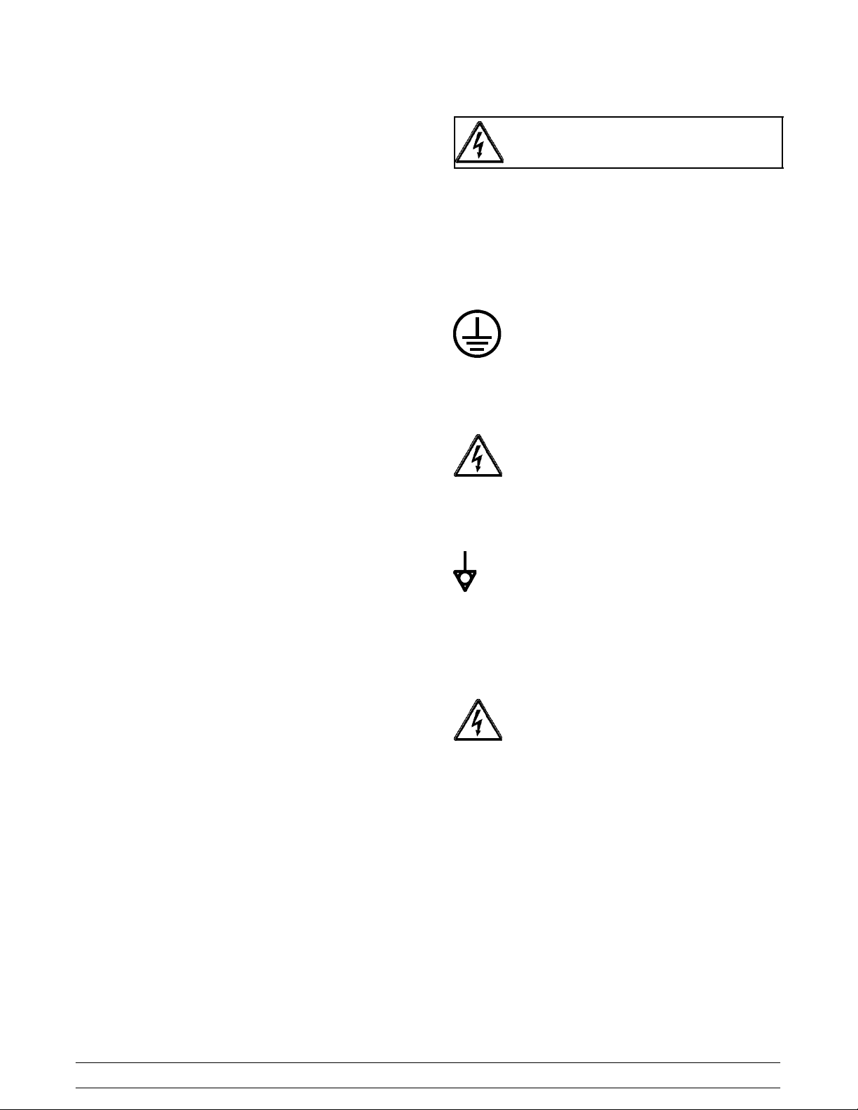
This unit is provided with an equipotential
grounding lug that is to be properly attached to the rear
of the frame by the authorized installer. The installation
location is marked by the equipotential bonding
symbol (5021 of IEC 60417-1) on both the removable
panel and the equipments frame.
Stationary appliances which are not equipped
with a power cord and a plug or another device to
disconnect the appliance from the power source must
have an all-pole disconnecting device with a contact
gap of at least 3 mm installed in the external
installation.
080828
2
Model 428To the Installer
Page 7

Appliances that are permanently connected to
fixed wiring and for which leakage currents may
exceed 10 mA, particularly when disconnected or not
used for long periods, or during initial installation, shall
have protective devices such as a GFI, to protect
against the leakage of current, installed by the
authorized personnel to the local codes.
Supply cords used with this unit shall be
oil-resistant, sheathed flexible cable not lighter than
ordinary polychloroprene or other equivalent synthetic
elastomer-sheathed cord (Code designation 60245
IEC 57) installed with the proper cord anchorage to
relieve conductors from strain, including twisting, at
the terminals and protect the insulation of the
conductors from abrasion.
Refrigerant
In consideration of our environment, Taylor
proudly uses only earth friendly HFC refrigerants. The
HFC refrigerant used in this unit is R404A. This
refrigerant is generally considered non-toxic and
non-flammable, with an Ozone Depleting Potential
(ODP) of zero (0).
However, any gas under pressure is potentially
hazardous and must be handled with caution.
NEVER fill any refrigerant cylinder completely with
liquid. Filling the cylinder to approximately 80% will
allow for normal expansion.
Use only R134a refrigerant that conforms to
the AHI standard 700 specification. The use of any
other refrigerant may expose users and operators to
unexpected safety hazards.
Beater Rotation
Beater rotation must be clockwise as viewed
looking into the freezing cylinder.
Note: The following procedures should be
performed by a trained service technician.
To correct rotation on a single-phase unit, change
the leads inside the beater motor. (Follow the
diagram printed on motor.)
Refrigerant liquid sprayed onto the skin may
cause serious damage to tissue. Keep eyes and skin
protected. If refrigerant burns should occur, flush
immediately with cold water. If burns are severe, apply
ice packs and contact a physician immediately.
Taylor reminds technicians to be cautious of
government laws regarding refrigerant recovery,
recycling, and reclaiming systems. If you have any
questions regarding these laws, please contact the
factory Service Department.
WARNING: R404A refrigerant used in
conjunction with polyolester oils is extremely moisture
absorbent. When opening a refrigeration system, the
maximum time the system is open must not exceed 15
minutes. Cap all open tubing to prevent humid air or
water from being absorbed by the oil.
120628
Model 428 To the Installer
3
Page 8

Section 2 To the Operator
The freezer you have purchased has been carefully
engineered and manufactured to give you
dependable operation. The Taylor Model 428, when
properly operated and cared for, will produce a
consistent quality product. Like all mechanical
products, they will require cleaning and
maintenance. A minimum amount of care and
attention is necessary if the operating procedures
outlined in this manual are followed closely.
This Operator’s Manual should be read before
operating or performing any maintenance on your
equipment.
Your Taylor freezer will NOT eventually compensate
for and correct any errors during the set-up or filling
operations. Thus, the initial assembly and priming
procedures are of extreme importance. It is strongly
recommended that personnel responsible for the
equipment’s operation, both assembly and
disassembly, sit down together and go through these
procedures in order to be properly trained and to
make sure that no misunderstandings exist.
In the event you should require technical assistance,
please contact your local authorized Taylor
Distributor.
Warranty is valid only if the parts are authorized
Taylor parts, purchased from an authorized Taylor
Distributor, and the required service work is provided
by an authorized Taylor service technician. Taylor
reserves the right to deny warranty claims on
equipment or parts if non--approved parts or
refrigerant were installed in the machine, system
modifications were performed beyond factory
recommendations, or it is determined that the failure
was caused by neglect or abuse.
Note: Constant research results in steady
improvements; therefore, information in this
manual is subject to change without notice.
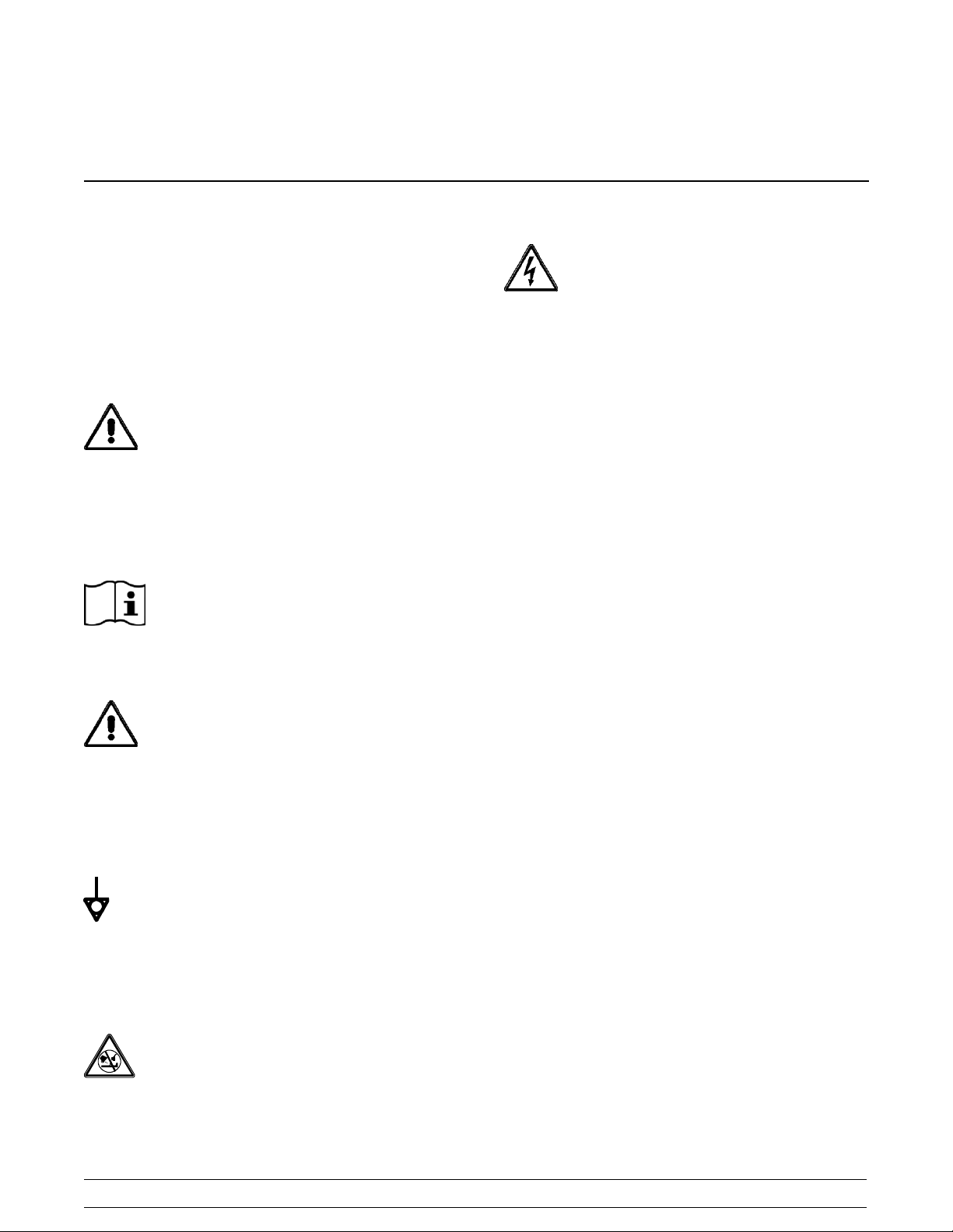
If the crossed out wheeled bin symbol is
affixed to this product, it signifies that this product is
compliant with the EU Directive as well as other
similar legislation in effect after August 13, 2005.
Therefore, it must be collected separately after its
use is completed, and cannot be disposed as
unsorted municipal waste.
The user is responsible for returning the product to
the appropriate collection facility, as specified by
your local code.
For additional information regarding applicable local
laws, please contact the municipal facility and/or
local distributor.
Compressor Warranty Disclaimer
The refrigeration compressor(s) on this machine are
warranted for the term indicated on the warranty
card accompanying this machine. However, due to
the Montreal Protocol and the U.S. Clean Air Act
Amendments of 1990, many new refrigerants are
being tested and developed, thus seeking their way
into the service industry . Some of these new
refrigerants are being advertised as drop-in
replacements for numerous applications. It should
be noted that, in the event of ordinary service to this
machine’s refrigeration system, only the refrigerant
specified on the affixed data label should be
used. The unauthorized use of alternate refrigerants
will void your compressor warranty. It will be the
owner’s responsibility to make this fact known to any
technician he employs.
It should also be noted that Taylor does not warrant
the refrigerant used in its equipment. For example, if
the refrigerant is lost during the course of ordinary
service to this machine, Taylor has no obligation to
either supply or provide its replacement either at
billable or unbillable terms. Taylor does have the
obligation to recommend a suitable replacement if
the original refrigerant is banned, obsoleted, or no
longer available during the five year warranty of the
compressor.
Taylor will continue to monitor the industry and test
new alternates as they are being developed. Should
a new alternate prove, through our testing, that it
would be accepted as a drop-in replacement, then
the above disclaimer would become null and void. To
find out the current status of an alternate refrigerant
as it relates to your compressor warranty, call the
local Taylor Distributor or the Taylor Factory. Be
prepared to provide the Model/Serial Number of the
unit in question.
110121
4
Model 428To the Operator
Page 9
Section 3 Safety
We, at Taylor Company, are concerned about the
safety of the operator when he or she comes in contact
with the freezer and its parts. Taylor has gone to
extreme efforts to design and manufacture built--in
safety features to protect both you and the service
technician. As an example, warning labels have been
attached to the freezer to further point out safety
precautions to the operator.
IMPORTANT -- Failure to adhere to the
following safety precautions may result in severe
personal injury or death. Failure to comply with
these warnings may damage the machine and its
components. Component damage will result in
part replacement expense and service repair
expense.
DO NOT operate the freezer without reading
this Operator Manual. Failure to follow this instruction
may result in equipment damage, poor freezer
performance, health hazards, or personal injury.
Per IEC 60335--1 and its part 2 standards,
“This appliance is to be used only by trained personnel.
It is not intended for use by children or people with
reduced physical, sensory, or mental capabilities, or
lack of experience and knowledge, unless given
supervision or instruction concerning the use of the
appliance by a person responsible for their safety.”
This unit is provided with an equipotential
grounding lug that is to be properly attached to the rear
of the frame by the authorized installer. The installation
location is marked by the equipotential bonding
symbol (5021 of IEC 60417-1) on both the removable
panel and the equipments frame.
S DO NOT operate the freezer unless it is
properly grounded.
S DO NOT operate the freezer with larger
fuses than specified on the freezer data
label.
S All repairs must be performed by an
authorized Taylor service technician. The
main power supplies to the machine must
be disconnected prior to performing any
repairs.
S Cord Connected Units: Only Taylor
authorized service technicians may install a
plug on this unit.
S Stationary appliances which are not
equipped with a power cord and a plug or
another device to disconnect the appliance
from the power source must have an all-pole
disconnecting device with a contact gap of
at least 3 mm installed in the external
installation.
S Appliances that are permanently connected
to fixed wiring and for which leakage
currents may exceed 10 mA, particularly
when disconnected or not used for long
periods, or during initial installation, shall
have protective devices such as a GFI, to
protect against the leakage of current,
installed by the authorized personnel to the
local codes.
S Supply cords used with this unit shall be
oil-resistant, sheathed flexible cable not
lighter than ordinary polychloroprene or
other equivalent synthetic
elastomer-sheathed cord (Code designation
60245 IEC 57) installed with the proper cord
anchorage to relieve conductors from strain,
including twisting, at the terminals and
protect the insulation of the conductors from
abrasion.
DO NOT use a water jet to clean or rinse the
freezer. Failure to follow these instructions may result
in serious electrical shock.
Model 428 Safety
Failure to follow these instructions may result in
electrocution. Contact your local authorized Taylor
Distributor for service.
110121
5
Page 10

S DO NOT allow untrained personnel to
operate this machine.
S DO NOT operate the freezer unless all
service panels and access doors are
restrained with screws.
S DO NOT remove any internal operating
parts (examples: freezer door, beater,
scraper blades, etc.) unless all control
switches are in the OFF position.
Failure to follow these instructions may result in severe
personal injury to fingers or hands from hazardous
moving parts.
This unit has many sharp edges that can
cause severe injuries.
S DO NOT put objects or fingers in the door
spout. This may contaminate the product
and cause severe personal injury from blade
contact.
S USE EXTREME CAUTION when removing
the beater asssembly. The scraper blades
are very sharp.
Cleaning and sanitizing schedules are
governed by your state or local regulatory agencies
and must be followed accordingly. Please refer to the
cleaning section of this manual for the proper
procedure to clean this unit.
IMPORTANT: DO NOT obstruct air intake and
discharge openings: 3” (76 mm) minimum air
clearance on both sides of the freezer. It is
recommended to place the rear of the unit against
the wall to prevent the recirculation of warm air.
Failure to follow this instruction may cause poor
freezer performance and damage to the machine.
For Indoor Use Only: This unit is designed to operate
indoors, under normal ambient temperatures of 70_ -
75_F(21_ -24_C). The freezer has successfully
performed in high ambient temperatures of
104_(40_C) at reduced capacities.
NOISE LEVEL: Airborne noise emission does not
exceed 78 dB(A) when measured at a distance of 1.0
meter from the surface of the machine and at a height
of 1.6 meters from the floor.
This freezer must be placed on a level
surface. Failure to comply may result in personal injury
or equipment damage.
080828
6
Model 428Safety
Page 11
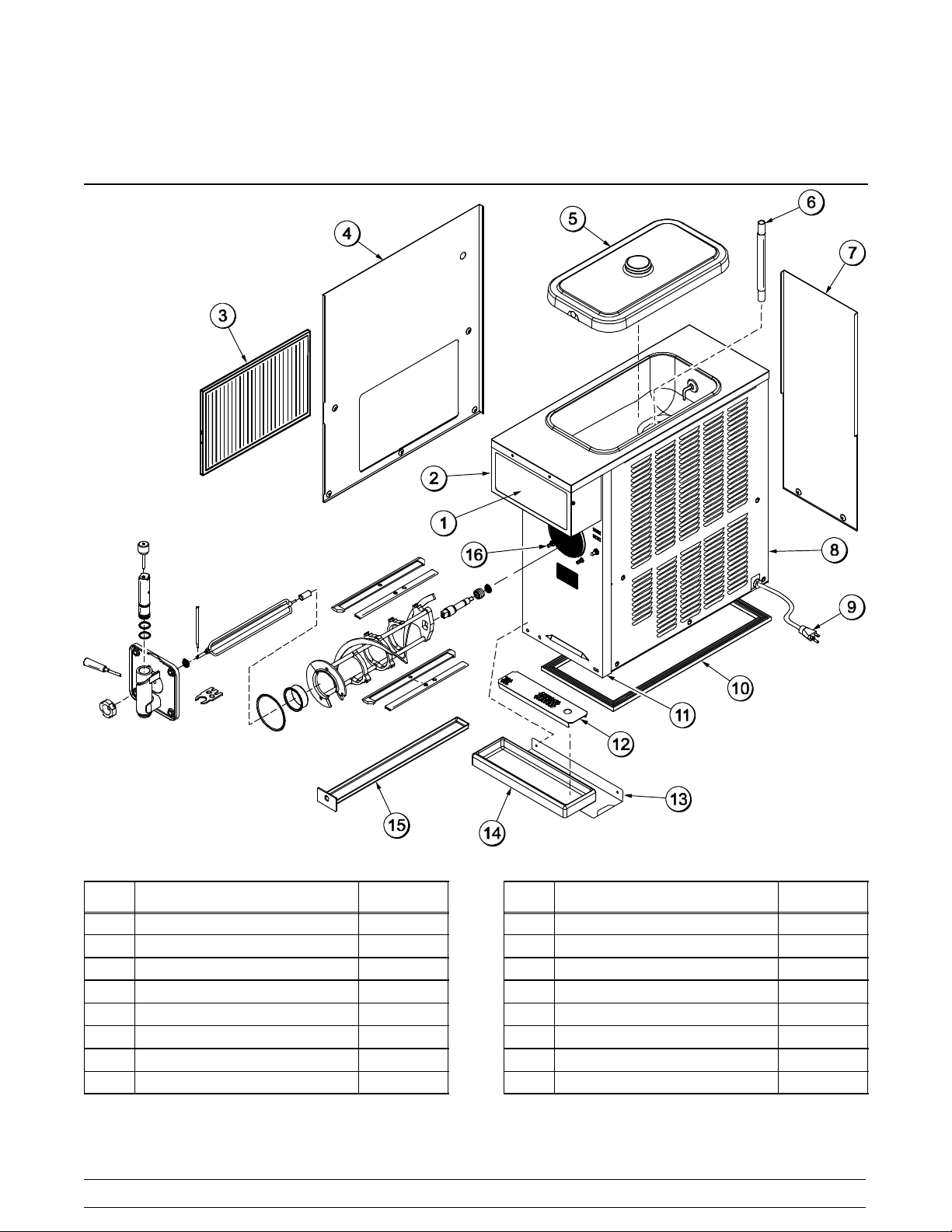
Section 4 Operator Parts Identification
Model 428
Figure 1
ITEM DESCRIPTION PART NO.
1 LENS-LIGHT 052952
2 PLATE A.-DEC LIGHTED X52936
3 FILTER-AIR-17 X 13 X 7/16 052951
4 PANEL A.-SIDE*LEFT X62592
5 COVER A.-HOPPER X51152
6 TUBE-FEED 5/16 HOLE SS 028967-7
7 PANEL-REAR 062594
8 PANEL-SIDE*RIGHT 052935
ITEM DESCRIPTION PART NO.
9 CORD-POWER-125V 045666
10 GASKET-BASE·PAN 062619
11 PANEL-FRONT 054933
12 SHIELD-SPLASH 052980
13 SHELF-DRIP·TRAY 052979
14 TRAY-DRIP 052978
15 PAN-DRIP 22-29/32 LONG 053048
16 STUD-NOSE·CONE-5/16-18 013496
NOTE: STANDARD DOOR SHOWN (NO PRIME PLUG)
101101
Model 428 Operator Parts Identification
7
Page 12
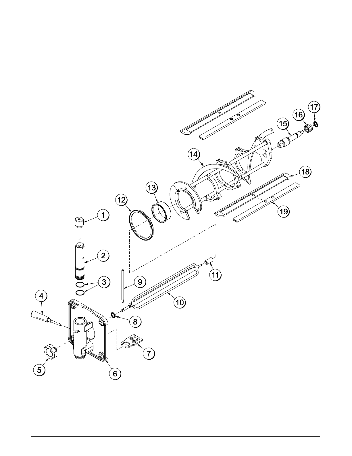
Beater Door Assembly With Standard Door (No Prime Plug)
120614
Figure 2
8
Model 428Operator Parts Identification
Page 13

Beater Door Assembly With Standard Door (No Prime Plug)
ITEM DESCRIPTION PART NO.
1 PIN A.-VALVE HANDLE X25929
2 VALVE-DRAW SLUSH 047734
3 O-RING-1”OD X .139W 032504
4 HANDLE A.-DRAW-SLUSH-BLK X47384
5 NUT-STUD 029880
6 DOOR A.-PARTIAL X39248-SER
7 BUSTER-ICE 047735
8 O-RING-.291 ID X .080W 018550
9 ARM-TORQUE 052450
10 TORQUE A. X14488
ITEM DESCRIPTION PART NO.
11 BEARING-GUIDE 014496
12 GASKET-DOOR 5.109”ID 014030
13 BEARING-FRONT 013116
14 BEATER A.-7QT-1 PIN X46233
15 SHAFT-BEATER 035418
16 SEAL-DRIVE SHAFT 032560
17 O-RING-7/8 OD X .139W 025307
18 BLADE-SCRAPER-PLASTIC 046237
19 CLIP-SCRAPER·BLADE8.75” 046238
*NOTE: OPTIONAL TORQUE A. = X27027-1
120614
Model 428 Operator Parts Identification
9
Page 14
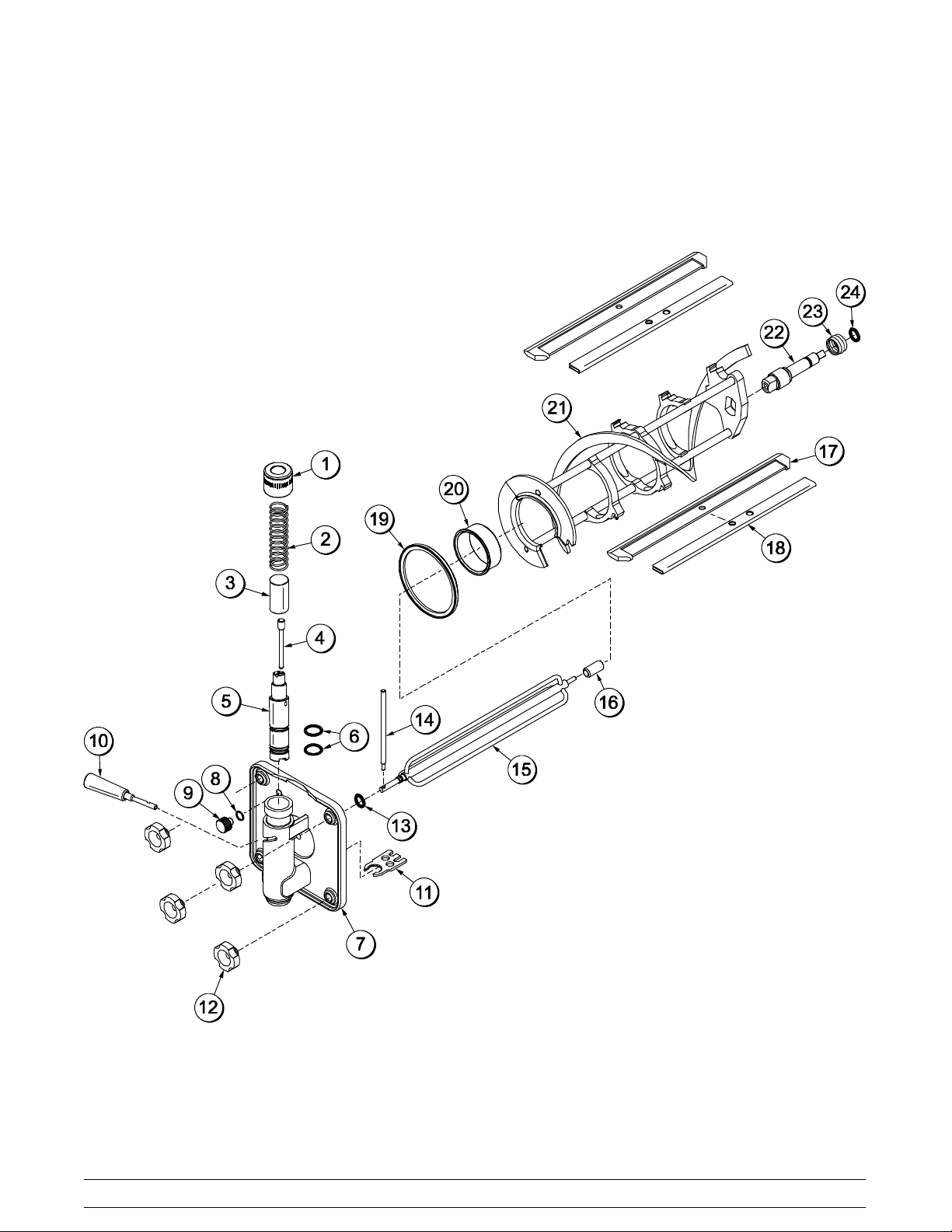
Beater Door Assembly With Self--Closing/Prime Plug Door
120614
Figure 3
10
Model 428Operator Parts Identification
Page 15

Beater Door Assembly With Self--Closing/Prime Plug Door
ITEM DESCRIPTION PART NO.
1 CAP A.--SPRING--RETAINER X54755
2 SPRING--COMP.970X.082X3.875 030344
3 PLUNGER--CAP DRAW SWITCH 080554
4 PIN-- HANDLE--VALVE 064864
5 VALVE-- DRAW--SLUSH 080662
6 O--RING -- 1” OD X .139 W 032504
7 DOOR A.--PARTIAL SELF CLOSE X80663
8 O-- RING-- .563 OD X .070W-- #013 043758
9 PLUG--PRIME 050405
10 HANDLE A. DRAW X47384
11 BUSTER-- ICE 047735
12 NUT-- STUD 029880
ITEM DESCRIPTION PART NO.
13 O-- RING -- .291 OD X .080 W 018550
14 ARM -- TORQUE 052450
15 TORQUE A. X14488
16 BEARING -- GUIDE 014496
17 BLADE -- SCRAPER PLASTIC 046237
18 CLIP -- SCRAPER BLADE 046238
19 GASKET -- DOOR 5.109” ID 014030
20 BEARING -- FRONT 013116
21 BEATER A. -- 7 QT. 1 PIN X46233
22 SHAFT -- BEATER 035418
23 SEAL -- DRIVE SHAFT 032560
24 O--RING 7/8 OD X .139 W 025307
120614
Model 428 Operator Parts Identification
11
Page 16

Accessories
ITEM DESCRIPTION PART NO.
1 KIT A.-TUNE UP X50413
2 BRUSH-MIX PUMP BODY-3”X7” 023316
3 BRUSH-DOUBLE ENDED 013072
4 BRUSH-REAR BRG 1IN.DX2IN 013071
5 BRUSH-DRAW VALVE 1X2X17 013073
120614
Figure 4
12
ITEM DESCRIPTION PART NO.
6 BRUSH--SYRUP PORT 045079
7 PAIL-MIX 10 QT. 013163
8 LUBRICANT-TAYLOR 4 OZ. 047518
*9 SANITIZER-- STERA SHEEN SEE NOTE
*NOTE: A sample container of sanitizer is sent with the
unit. For reorders, order Stera Sheen part no. 055492
(100 2 oz. packs) or Kay-- 5 part no. 041082 (200 packs).
Model 428Operator Parts Identification
Page 17

Section 5 Important: To the Operator
Figure 5
ITEM DESCRIPTION PART NO.
1 SWITCH-- ROCKER AUTO/
WASH (POWER SWITCH)
2 SWITCH-- TOGGLE-- SPST 3/4
HP/250V (DISPLAY LIGHT)
3 BUSHING A.--TORQUE
(VISCOSITY ADJUSTMENT)
LIGHT-- AMBER --RECT--12VDC
4
ADD MIX
048420
012626
X50399--SER
052486--02
ITEM DESCRIPTION PART NO.
5 LIGHT-- AMBER --RECT--12VDC
MIX OUT
6 SWITCH-- TOGGLE-- SPST 3/4
HP/250V (STANDBY SWITCH)
6a BOOT-- SWITCH-- TOGGLE 043398
NOTE: STANDARD DOOR SHOWN (NO PRIME PLUG)
052487--02
012626
081002
Model 428 Important: To the Operator
13
Page 18

Power Switch
The center position is OFF. The right position is
AUTO, which activates the beater motor and the
refrigeration system. The left position is WASH,
which activates the beater motor only.
Display Light Switch
Standby Switch (Toggle Switch)
This switch determines which mode of operation the
freezing cylinder is operating in. The left position
places the unit in the AUTO mode. The right position
places the unit in the STANDBY mode.
The display light switch is located under the control
channel. The left position is “OFF”. The right position
is “ON”, and activates the display light.
Viscosity Adjustment
The viscosity (thickness) of the product can be
adjusted by turning the viscosity adjustment screw
on the right side of the unit, under the display light.
Turn the viscosity adjustment screw clockwise for a
thicker product, or counterclockwise for a thinner
product. After making an adjustment, allow the
refrigeration system to cycle 2 or 3 times to
accurately evaluate the viscosity.
Do not use metal objects to press the
reset button. Failure to follow this instruction may
result in electrocution.
Indicator Light - “ADD MIX”
Note: The power switch must be in the AUTO position
in order for the standby switch to function.
Reset Mech an ism
Should an overload condition occur, the freezer will
automatically shut down. T o properly reset the
freezer, place the toggle switch in the OFF position.
Wait two or three minutes; then press the reset
button located in the left side panel. Place the toggle
switch in the WASH position and observe the
freezer’s performance; return the toggle switch to
the AUTO position.
A mix level indicating light is located on the front of
the machine. The light flashes to indicate when the
mix hopper has a low supply of product and should
be refilled as soon as possible.
Indicator Light - “MIX OUT”
A mix out indicating light is located on the front of
the machine. When the light is flashing, it indicates
that the hopper is empty and the mix supply needs
replenishing. To prevent damage to the unit,
refrigeration discontinues automatically when the
MIX OUT indicator light is flashing.
080313
14
Figure 6
Model 428Important: To the Operator
Page 19

Section 6 Operating Procedures
The Model 428 freezer is designed to produce shake
or slush product at the desired thickness. This unit
has a 7 quart freezing cylinder.
We begin our instructions at the point where we
enter the store in the morning and find the parts
disassembled and laid out to air dry from the
previous night’s brush cleaning.
These opening procedures will show you how to
assemble these parts into the freezer, sanitize them,
and prime the freezer with fresh mix in preparation
to serve your first portion.
If you are disassembling the machine for the first
time or need information to get to this point in our
instructions, turn to page 26, “Disassembly”, and
start there.
Assembly
Note: When lubricating parts, use an approved food
grade lubricant (example: Taylor Lube).
Step 1
Slide the o--ring into the groove on the drive shaft.
Lubricate the o-ring and shaft portion that comes in
contact with the bearing. DO NOT lubricate the square
end of the drive shaft.
Note: To ensure that the mix does not leak out of the
back of the freezing cylinder, the middle section of the
boot seal should be convex or extend out from the seal.
If the middle section of the boot seal is concave or
extending into the middle of the seal, invert the seal.
Figure 8
Step 2
Lubricate the boot seal groove and slide the boot seal
over the shaft and groove until it snaps into place. Fill
the inside portion of the seal with 1/4” more lubricant.
Install the drive shaft.
Figure 7
Model 428 Operating Procedures
15
Figure 9
Page 20

Step 3
Insert the drive shaft into the rear shell bearing and
engage the square end firmly into the female socket of
the drive unit. Be certain that the drive shaft fits into the
drive coupling without binding.
Figure 10
Step 4
Check scraper blades for any nicks or signs of wear.
If any nicks are present or if the blade is worn, replace
both blades.
Step 5
Holding the blades in position, insert the beater
assembly into the freezing cylinder, and slide the
assembly into position over the drive shaft. Turn the
beater slightly to be certain that the beater is properly
seated.
When in position, the beater will not protrude beyond
the front of the freezing cylinder.
Figure 12
Step 6
Install the white plastic guide bearing on the short end
of the torque rotor. Slide the o-ring into the groove on
the long end of the torque rotor and lubricate the o-ring.
Do not lubricate the guide bearing.
Figure 11
If blades are in good condition, install the scraper
blade clip over the scraper blade. Place the rear
scraper blade over the rear holding pin (knife edge
to the outside). Holding the blade on the beater, turn
it over and install the front blade the same way.
16
Figure 13
Model 428Operating Procedures
Page 21

Step 7
Insert the torque rotor end with the guide bearing into
the pilot hole in the center of the drive shaft. The hole
in the torque rotor shaft should be rotated to the 12
o’clock position.
Figure 14
Step 9
Insert the draw valve into the door, leaving
approximately 1/2” of the valve sticking out the top of
the door.
Figure 16
Step 10
Rotatethe draw valve sothe flatson thetop ofthe draw
valve are perpendicular to the door face.
Freezer Door Assembly -- Standard Door
(No Prime Plug)
Note: The Model 428 comes equipped with two
door options: a standard door without a prime
plug or a self--closing door with a prime plug.
Follow the appropriate assembly procedures for your
style door. (For self--closing/prime plug door assembly
instructions, go to page 18 and perform Steps A -- L.)
Step 8
Install the o-rings on the draw valve and lubricate.
Figure 17
Step 11
Insert the ice buster through the door spout and into
the slot located just above the lower o-ring.
Figure 15
Model 428 Operating Procedures
17
Figure 18
120418
Page 22

Step 12
With the ice buster in place, rotate the draw valve to
allow installation of the draw handle. This will lock the
ice buster in place. Install the draw handle pin, and
close the draw valve by moving the handle to the left.
Step 15
Position the torque arm by inserting it through the slot
in the torque switch arm and down into the hole in the
torque rotor which protrudes from the door. Verify
proper installation by moving the torque rotor back and
forth to be sure it moves freely and easily.
Figure 19
Step 13
Place the large rubber gasket into the groove on the
back side of the freezer door . Slide the white, plastic
front bearing onto the bearing hub, making certain that
the flanged end of the bearing is resting against the
freezer door. DO NOT lubricate the door gasket or
front bearing.
Figure 21
Proceed to Step 16 on page 21.
Freezer Door Assembly -- Self--Closing/
Prime Plug Door
Note: The Model 428 comes equipped with two
door options: a standard door without a prime
plug or a self--closing door with a prime plug.
Follow the appropriate assembly procedures for your
style door. (For standard door ([no prime plug]
assembly instructions, go to page 17 and perform
Steps 8 -- 15).
Step A -- Self--Closing Door Assembly
Install the o--rings on the draw valve and lubricate.
Figure 20
Step 14
Position the freezer door on the 4 studs on the front of
the freezing cylinder. Install the handscrews. Tighten
equally in a criss-cross pattern to insure the door is
snug. Do not over-tighten.
18
Figure 22
Model 428Operating Procedures
Page 23

Step B -- Self--Closing Door Assembly
Insert the draw valve into the door.
Figure 23
Step C -- Self--Closing Door Assembly
Rotate the draw valve so the groove on the top of
the draw valve is perpendicular to the door face.
Step E -- Self--Closing Door Assembly
With the ice buster in place, rotate the draw valve to
allow installation of the draw handle. This will lock
the ice buster in place. With the draw handle in
place, install the draw handle pin. Close the draw
valve by moving the handle to the left.
Figure 26
Step F -- Self--Closing Door Assembly
Install the draw valve spring, draw switch cap
plunger, and cap.
Figure 24
Step D -- Self--Closing Door Assembly
Insert the ice buster through the door spout and into
the slot located just above the lower o--ring.
Figure 25
Figure 27
Model 428 Operating Procedures
19
Page 24

Step G -- Self--Closing Door Assembly
Place the o--ring onto the prime plug and lubricate.
Figure 28
Step H -- Self--Closing Door Assembly
Screw the prime plug into position on the front of the
door.
Step J -- Self--Closing Door Assembly
Slide the white, plastic front bearing onto the bearing
hub, making certain that the flanged end of the
bearing is resting against the freezer door . DO NOT
lubricate the door gasket or front bearing.
Figure 31
Figure 29
Step I -- Self--Closing Door Assembly
Place the large rubber gasket into the groove on the
back side of the freezer door.
Step K -- Self--Closing Door Assembly
Position the freezer door onto the four studs on the
front of the freezing cylinder and push the door into
place. Install the four handscrews onto the studs
and tighten them equally in a crisscross pattern to
insure that the door is snug. DO NOT over--tighten
the handscrews.
Note: If the freezer door does not fit into place
easily, position the open end of the beater assembly
in the 11 o'clock position.
Figure 30
20
Figure 32
Model 428Operating Procedures
Page 25

Step L -- Self--Closing Door Assembly
Position the torque arm by inserting it down into the
hole on the torque rotor which protrudes from the
door. Verify proper installation by moving the torque
rotor back and forth to be sure it moves freely.
Figure 33
Proceed to Step 16.
Step 16
Slide the long drip pan into the hole in the front panel.
Step 17
Install the front drip tray and splash shield beneath the
door spout.
Figure 35
Step 18
With sanitized hands, or a plastic sanitized glove, lay
the air/mix feed tube (optional) in the bottom of the mix
hopper.
Figure 34
Model 428 Operating Procedures
21
Figure 36
050415
Page 26

Sanitizing
Step 1
Prepare a 2--1/2 gallon (9.5 liter) pail of
cleaning/sanitizing solution with an active chlorine
concentrate of 100 -- 200 PPM (parts per million).
USE WARM WATER AND FOLLOW THE
MANUFACTURER’S SPECIFICATIONS.
Step 2
Pour the sanitizing solution into the hopper and allow
it to flow into the freezing cylinder.
Step 5
Place an empty mix pail beneath the door spout and
move the draw handle to the right. Draw off all the
sanitizing solution. When the sanitizer stops flowing
from the door spout, move the draw handle to the left
and place the power switch in the OFF position.
Figure 37
Step 3
While the solution is flowing into the freezing cylinder,
brush clean the mix hopper, air/mix feed tube
(optional) and mix inlet hole.
Step 4
Place the power switch in the WASH position. This
will agitate the sanitizing solution in the freezing
cylinder. Allow the solution to agitate for five
minutes.
Figure 38
Figure 39
Step 6
Stand the air/mix feed tube (optional) in the corner of
the hopper.
Figure 40
080428
22
Model 428Operating Procedures
Page 27

Priming the Freezing Cylinder
Step 1
With a pail beneath the door spout, move the draw
handle to the right. Pour two gallons (7.6 liters) of
FRESH mix into the hopper and allow it to flow into the
freezing cylinder. This will force out any remaining
sanitizing solution. When full strength mix is flowing
from the door spout, move the draw handle to the left.
Step 2
When mix has stopped bubbling down into the freezing
cylinder, install the air/mix feed tube (optional) in the
mix inlet hole with the hole side down.
Figure 42
Step 4
Self--Closing Door Only: Loosen the prime plug.
When product starts to leak from the bleed port, tighten
the prime plug. Allow the product to continue filling the
mix hopper until the upper mix level probe is satisfied
and the fill system shuts off.
Figure 41
Step 3
Place the power switch in the AUTO position. When
the unit cycles off, the product will be at serving
viscosity. The viscosity (thickness) of the product can
be adjusted by turning the viscosity adjustment screw
on the upper right side under the display light. Turn the
viscosity adjustment screw clockwise for a thicker
product, or counterclockwise for a thinner product.
After making an adjustment, allow the refrigeration
system to cycle 2 or 3 times to accurately evaluate the
viscosity.
Figure 43
050415
Model 428 Operating Procedures
23
Page 28

Step 5
Place the mix hopper cover in position. For proper
operation, there must be a substantial amount of mix
in the hopper. If the ADD MIX light illuminates, refill the
mix hopper as soon as possible.
Figure 44
Closing Procedure
To disassemble this unit, the following items will be
needed:
S Two cleaning pails
S Necessary brushes (provided with freezer)
S Cleaner
S Single service towels
Draining Product From The
Freezing Cylinder
Step 1
Place the power switch in the OFF position as far
ahead of cleaning time as possible to allow frozen
product to soften for easier cleaning.
Step 2
Remove the hopper cover and the air/mix feed tube (if
the unit is equipped with an air/mix feed tube). Take
these parts to the sink for cleaning.
Step 3
If local health codes permit the use of rerun,place
a sanitized, NSF approved stainless steel rerun
container beneath the door spout. Place the power
switch in the WASH position and move the draw
handle to the right. When product stops flowing from
the door spout, move the draw handle to the left and
place the power switch in the OFF position. Place the
sanitized lid on the rerun container and place it in the
walk--in cooler.
Note: If local health codes DO NOT permit the use
of rerun, the product must be discarded. Drain the
product into a mix pail and properly discard it.
ALWAYS FOLLOW LOCAL HEALTH CODES
080828
24
Model 428Operating Procedures
Page 29

Rinsing
Step 1
Pour two gallons (7.6 liters) of cool, cleanwater into the
mix hopper. With the brushes provided, scrub the mix
hopper, float switch, and the mix inlet hole.
Cleaning
Step 1
Prepare a 2--1/2 gallon (9.5 liter) pail of
cleaning/sanitizing solution with an active chlorine
concentrate of 100 -- 200 PPM (parts per million).
USE WARM WATER AND FOLLOW THE
MANUFACTURER’S SPECIFICATIONS.
Step 2
Pour the cleaning solution into the hopper and allow
it to flow into the freezing cylinder.
Step 3
While the solution is flowing into the freezing
cylinder, brush-clean the mix hopper, float switch,
and mix inlet hole.
Figure 45
Step 2
With a pail beneath the door spout, place the power
switch in the WASH position and move the draw
handle to the right. Drain all the rinse water from the
freezing cylinder. When the rinse water stops flowing
from the door spout, move the draw handle to the left
and place the power switch in the OFF position.
Repeat this procedure until the rinse water being
drawn from the freezing cylinder is clear.
Step 4
Place the power switch in the WASH position. This
will agitate the cleaning solution in the freezing
cylinder.
Step 5
Place an empty pail beneath the door spout and
move the draw handle to the right. Draw off all the
cleaning solution. When the solution stops flowing
from the door spout, move the draw handle to the
left, and place the power switch in the OFF position.
080428
Model 428 Operating Procedures
25
Page 30

Disassembly
Step 3
From the freezer door, remove the draw valve, ice
buster, front bearing, and gasket. Remove the prime
plug (self--closing door, only). Remove all o-rings.
BE SURE THE POWER SWITCH IS IN
THE OFF POSITION. Failure to follow this
instruction may result in severe personal injury from
hazardous moving parts.
Step 1
Remove the torque arm, handscrews, freezer door,
torque rotor, beater assembly, scraper blades and
drive shaft from the freezing cylinder. Take these
parts to the sink for cleaning.
Step 2
Remove the front drip tray and the splash shield.
Take these parts to the sink for cleaning.
Step 3
Remove the rear drip pan from the front panel. Note:
If the drip pan is filled with an excessive amount of
mix, it is an indication the drive shaft seal should be
replaced or properly lubricated.
Brush Cleaning
Step 1
Prepare a sink of cleaning/sanitizing solution with an
active chlorine concentrate of 100 -- 200 PPM (parts
per million). USE WARM WATER AND FOLLOW
THE MANUFACTURER’S SPECIFICATIONS.
Make sure all brushes provided with the freezer are
available for brush cleaning.
Note: To remove the o-ring, use a single service towel
to grasp the o-ring, and apply pressure in an upward
direction until the o-ring pops out of its groove. With the
other hand, push the top of the o-ring forward until it
rolls out of the groove and can be removed easily.
Step 4
Thoroughly brush clean all disassembled parts in the
cleaning solution, making sure all lubricant and mix film
is removed. Place all the cleaned parts on a clean, dry
surfacetoairdry.
Step 5
Return to the freezer with a small amount of cleaning
solution. Brush-clean the rear shell bearing at the back
of the freezing cylinder with the black bristle brush.
IMPORTANT: Follow the label directions. Too
STRONG of a solution can cause parts damage,
while too MILD of a solution will not provide
adequate cleaning.
Step 2
Remove the o-ring and seal from the drive shaft.
Remove the o-ring and the bearing from the torque
rotor.
080313
Figure 46
Step 6
Wipe clean all exterior surfaces of the freezer.
26
Model 428Operating Procedures
Page 31

Section 7 Important: Operator Checklist
During Cleaning and Sanitizing:
ALWAYS FOLLOW LOCAL HEALTH CODES
Cleaning and sanitizing schedules are governed
by federal, state, or local regulatory agencies, and
must be followed accordingly. If the unit has a
“Standby mode”, it must not be used in lieu of
proper cleaning and sanitizing procedures and
frequencies set forth by the ruling health
authority. The following check points should be
stressed during the cleaning and sanitizing
operations.
CLEANING AND SANITIZING MUST BE
PERFORMED DAILY.
Troubleshooting Bacterial Count:
j 1. Thoroughly clean and sanitize machine
regularly, including complete disassembly and
brush cleaning.
j 2. Use all brushes supplied for thorough cleaning.
The brushes are specially designed to reach all
mix passageways.
j 3. Use the white bristle brush to clean the mix feed
tube, which extends from the hopper down to
the rear of the freezing cylinder.
j 4. Use the black bristle brush to thoroughly clean
the rear shell bearing located at the rear of the
freezing cylinder. Be sure to have a generous
amount of cleaning solution on the brush.
j 5. IF LOCAL HEALTH CODES PERMIT THE
USE OF RERUN, make sure the mix rerun is
stored in a sanitized, covered stainless steel
container and used the following day. DO NOT
prime the machine with rerun. When using
rerun, skim off the foam and discard, then mix
the rerun with fresh mix in a ratio of 50/50 during
the day’s operation.
j 6. On a designated day of the week, run the mix as
low as feasible and discard after closing. This
will break the rerun cycle and reduce the
possibility of high bacteria and coliform counts.
j 7. Properly prepare the cleaning and sanitizing
solutions. Read and follow label directions
carefully. Too strong of a solution may damage
the parts and too weak of a solution will not do
an adequate job of cleaning or sanitizing.
j 8. Temperature of mix in mix hopper and walk-in
cooler should be below 40_F. ( 4 .4_C.).
Regular Maintenance Checks:
j 1. Replace scraper blades that are nicked,
damaged or worn down. Before installing the
beater, be certain the scraper blade is properly
attached.
j 2. Check rear shell bearing for signs of wear
(excessive mix leakage in drip pan) and be
certain it is properly cleaned.
j 3. Using a screwdriver and cloth towel, keep the
rear shell bearing and the female square drive
socket clean and free of lubricant and mix
deposits.
j 4. Dispose of o-rings and seals if they are worn,
torn, or fit too loosely, and replace with new
ones.
j 5. Follow all lubricating procedures as outlined in
“Assembly”.
j 6. Check the condenser(s) for accumulation of dirt
and lint. Dirty condensers will reduce the
efficiency and capacity of the machine.
Condensers should be cleaned monthly with a
soft brush. Never use screwdrivers or other
metal probes to clean between the fins.
Note: For machines equipped with an air filter,
it will be necessary to vacuum clean the filters
on a monthly schedule.
051207
Model 428 Important: Operator Checklist
27
Page 32

Winter Storage
If the place of business is to be closed during the
winter months, it is important to protect the freezer
by following certain precautions, particularly if the
building is to be left unheated and subject to freezing
conditions. Disconnect the freezer from the main
power source to prevent possible electrical damage.
Your local Taylor Distributor can perform this service
for you.
Wrap detachable parts of the freezer such as beater,
blades, drive shaft, and freezer door, and place in a
protected dry place. Rubber trim parts and gaskets
can be protected by wrapping with moisture-proof
paper. All parts should be thoroughly cleaned of
dried mix or lubrication accumulations which attract
mice and other vermin.
28
Model 428Important: Operator Checklist
Page 33

Section 8 Troubleshooting G uide
PROBLEM PROBABLE CAUSE REMEDY PA GE
REF.
1. No product being
dispensed.
2. Unit will not operate in the
AUTO or “WASH” mode.
a. Power switch is in the
OFF position.
b. Improper mixing of
product.
c. Inadequate mix in hopper. c. Fill hopper with mix. 24
d. Product frozen-up in
freezing cylinder.
e. Unit out on reset. e. Place power switch in the
f. Beater assembly is not
rotating at all or
counterclockwise. Power
switch is not in AUTO.
g. Unit unplugged at wall
receptacle.
h. Tripped circuit breaker or
blown fuse.
a. Unit unplugged at wall
receptacle.
a. Place power switch in the
AUTO position.
b. Carefully follow directions
for mixing product.
d. Adjust viscosity
adjustment accordingly.
OFF position. Press the
reset button. Return
power switch to AUTO.
f. The power switch must be
in AUTO. If beater is
rotating counterclockwise,
call service technician to
correct rotation.
g. Plug in power cord. ---
h. Reset circuit breaker or
replace fuse.
a. Plug in power cord. ---
23
---
13
14
---
1
b. Tripped circuit breaker or
blown fuse.
c. Unit out on reset. c. Place the power switch in
3. No compressor operation
in the AUTO mode.
Model 428 Troubleshooting Guide
a. Beater motor is out on
overload.
b. Condenser dirty A/C. b. Clean condenser monthly. 27
29
b. Reset circuit breaker or
replace fuse.
the OFF position. Press
the reset button. Return
power switch to AUTO.
a. Place power switch in
OFF position. Press the
reset button. Return
power switch to AUTO.
---
14
13
Page 34

PROBLEM PROBABLE CAUSE REMEDY PA GE
REF.
4. Product too thick. a. Inadequate mix in hopper. a. Fill hopper with mix. 24
b. Improper mixing of
product.
c. The viscosity adjustment
is set incorrectly.
d. The torque arm is not
installed.
5. Product too thin. a. Missing, incorrectly
installed, or bad scraper
blade.
b. Improper mixing of
product.
c. The viscosity adjustment
is set incorrectly.
d. Incorrect beater rotation. d. Contact service
e. Dirty condensers. e. Clean regularly. 27
6. Scored walls of freezing
cylinder.
a. Broken pin on beater
assembly.
b. Front bearing worn or
missing.
b. Carefully follow directions
for mixing product.
c. Adjust the viscosity
control.
d. Install the torque arm. 18
a. Install or replace scraper
blade.
b. Carefully follow directions
for mixing product.
c. Adjust accordingly. 13
technician.
a. Repair or replace beater
assembly.
b. Replace or install front
bearing.
---
13
16
---
---
---
16
7. Excessive leakage into
rear drip pan.
8. Excessive leakage from
door spout.
9. Unable to remove drive
shaft.
a. Improper or inadequate
lubrication of drive shaft
seal.
b. Bad or missing seal on
drive shaft.
c. Worn rear shell bearing. c. Contact service technician
d. Seal is installed inside out. d. Install the seal correctly. 15
a. Improper or inadequate
lubrication of draw valve
o-rings.
b. Bad or missing o-rings on
draw valve.
a. Lubrication on square end
of drive shaft.
b. Rounded corners of drive
shaft, drive coupling, or
both.
a. Use correct lubricant
(Taylor Lube) and follow
lubrication procedures.
b. Replace seal every 3
months.
for replacement.
a. Use correct lubricant
(Taylor Lube) and follow
lubrication procedures.
b. Replace o-rings every 3
months.
a. Do not lubricate square
end. Contact service
technician for
replacement.
b. Contact service technician
to replace drive shaft,
drive coupling, or both.
15
31
---
15
31
15
---
30
Model 428Troubleshooting Guide
Page 35

Section 9 Parts Replacement Schedule
PART DESCRIPTION EVERY 3
MONTHS
Drive Shaft Seal X 1
Drive Shaft O-Ring X 1
Scraper Blade X 1
Freezer Door Gasket X 1
Front Bearing X 1
Draw Valve O-Rings X 2
Black Bristle Brush - 1” x 2” Inspect & Replace
White Bristle Brush -1-1/2” x 2” Inspect & Replace
White Bristle Brush - 3” x 7” Inspect & Replace
Refer to the Parts List on the next page when ordering the above parts.
EVERY 6 MONTHS ANNUALLY QUANTITIES
REPLACED
Minimum 1
if Necessary
Minimum 1
if Necessary
Minimum 1
if Necessary
TO BE
Model 428 Parts Replacement Schedule
31
Page 36

Section 10 Parts List
REMARKS
CLASS
QTY. WARR.
NUMBER
DESCRIPTION PART
+SOCKET--FLUORESCENT BULB--COMP 066443 1 103
+GUIDE-- DRIP SEAL 028992 1 000
+NUT--BRASS BEARING 028991 1 000
+WASHER--BEARING LOCK 012864 1 000
+BLADE--SCRAPER --PLASTIC 9-- 13/16L 046237 2 000
ACCUMULATOR-- COPPER 2”DIA 10”LG 047062 1 103
ARM-- TORQUE *432* 052450 1 103
BALLAST--120V 60HZ 052911--12 1 103 042812H000 -- 115V 60HZ 1PH
BALLAST--ELECTRONIC 13W 066441--40 1 103 042827HW00 -- 208-- 230V 60HZ 1PH
BEARING-- FRONT 013116 1 000
BEARING-- GUIDE 014496 1 000
MODEL 042812H000 -- 115V 60HZ 1PH -- A/C -- TECUMSEH-- (R404A) &
MODEL 042827HW00 -- 208 --230V 60HZ 1PH -- A/C--TECUMSEH-- (R404A) -- ROHS COMPLIANT
+ Available Separately
120628
BEARING-- REAR SHELL *PLASTIC* 032511 1 000
Parts List Model 428
BEATER A.--7QT--1 PIN-- SUPPORT X46233 1 103
32
+CLIP-- SCRAPER BLADE*8.75 INCH* 046238 2 103
BELT-- AX31 041575 1 000 REPLACED 004227
BLOCK--TERMINAL 2P-- L1,N 039421 1 103
BLOCK--TERMINAL --7 POLE GREEN 024156 1 103
BRUSH--DOUBLE ENDED--PUMP&FEED T 013072 1 000
BRUSH--DRAW VALVE 1”ODX2”X17”L 013073 1 000
BRUSH--MIX PUMP BODY --3”X7”WHITE 023316 1 000
BRUSH--REAR BRG 1IN.DX2IN.LGX14 013071 1 000
BRUSH--SYRUP PORT 045079 1 000
+SOCKET--FLUORESCENT LAMP 049700 1 103
BULB--FLUORESCENT LIGHT-- U-- SHAPE 052910--12 1 000 042812H000 -- 115V 60HZ 1PH
BULB--FLUORESCENT-- COMPACT-- 066442 1 103 042827HW00 -- 208 --230V 60HZ 1PH
+BRACKET--SOCKET-- 13W COMPCT 066445 1 103
CAP--RESTRICTOR 020213 1 000
+CAPACITOR--RUN-- 25UF/370VAC 023739 1 103 042812H000 -- 115V 60HZ 1PH
COMPRESSOR AKA9455ZXA--AK171AT 052906--12 1 512 042812H000 -- 115V 60HZ 1PH
+CAPACITOR--START-- 72--88UF/250V 039557-- 27 1 103 042812H000 -- 115V 60HZ 1PH
Page 37

CLASS
QTY.PART
NUMBER
DESCRIPTION REMARKSWARR.
CHIP-- SOFTWARE *428* TORQUE CTR X40784-- SER 1 103
CONTROL--430 TORQUE--ROHS X65403 --SER 1 103 042827HW00 -- 208-- 230V 60HZ 1PH
CONTROL--ROHS-- TORQUE CONTROL X64270 --SER 1 103
CORD-- POWER--125V-- NEMA 5--20P--8’L 045666 1 103 042812H000 -- 115V 60HZ 1PH
CORD--POWER HARMONIZED *42 066395-- 95 1 103 042827HW00 -- 208--230V 60HZ 1PH
COVER A.--HOPPER *340*DDO*BLACK X51152 1 103
DAMPER A.--FAN MOTOR X20320 1 103 042827HW00 -- 208 --230V 60HZ 1PH
DECAL--DEC-- TAYLOR DOMED 053761 1 000
DECAL--INST --CLN HPR 019029 1 000
33
DECAL--SW-- CTRL--SLUSH--SYMBOL 042941 1 000
DECAL--TROUBLESHOOT 038374 1 000
+PIN A.-- VALVE HANDLE X25929 1 103
+HANDLE A.--DRAW-- SLUSH--BLACK X47384 1 103
+VALVE-- DRAW *SLUSH* ICE BUSTER 047734 1 103 REPLACED 051797 AS OF M6010000 & UP
+O--RING--1”OD X .139W 032504 2 000
+BUSTER--ICE 047735 1 103
DIAGRAM--WIRING *428* 062598--12 1 000 042812H000--115V 60HZ 1PH -- 9/1/2005 AND UP
DIAGRAM--WIRING *428* 052976--12 1 000
DIAGRAM--WIRING *428* 062598--27 1 000 042827HW00 -- 208 --230V 60HZ 1PH
DOOR A.-- PARTIAL *340--350-- 450* X39248--SER 1 103
DRYER--FILTER 1/4 X 1/4 SOLDER 048878 1 000
FILTER-- AIR--17 X 13 X 7/16 052951 1 000
FILTER--CORCOM 6EH1 040140--001 1 103
GASKET--BASE PAN *428*OVRRN SHL 062619 1 000
GASKET--BASE PAN *428* 052953 1 000
GASKET--FRONT PANEL 049031 1 000
+CAPACITOR--RUN 15UF/370V 027087 1 103 042827HW00 -- 208 --230V 60HZ 1PH
+CAPACITOR--START 72--88UF/3 039567 1 103 042827HW00 -- 208-- 230V 60HZ 1PH
+RELAY-- START--COMPRESSOR 039556 1 103 042812H000 -- 115V 60HZ 1PH
COMPRESSOR AKA9462ZXD--AK1 049302--27 1 512 042827HW00 -- 208 --230V 60HZ 1PH
+ Available Separately
+RELAY-- START--COMPRESSOR 048150 1 103 042827HW00 -- 208-- 230V 60HZ 1PH
CONDENSER--A/C--15.875LX12HX1.87 052905 1 103
Model 428 Parts List
GEAR A.*REDUCER 4.92:1 SERVICE 015985--SER 1 212
Page 38

CLASS
QTY.PART
NUMBER
DESCRIPTION REMARKSWARR.
BEARING-- FRONT 013116 1 000
BEARING-- GUIDE 014496 1 000
GASKET--DOOR 5.109”ID X 5.630OD 014030 1 000
O-- RING-- .291 ID X .080W 018550 1 000
O-- RING-- .563 OD X .070W-- #013 043758 1 000
O-- RING-- 1”OD X .139W 032504 2 000
O-- RING-- 7/8 OD X .139W 025307 1 000
SEAL--DRIVE SHAFT 032560 1 000
GUIDE A.--DRIP PAN *428* X52925 1 103
HARNESS--WIRE *428* HI VOLT--OVR 062582--12 1 103
HARNESS--WIRE *428* LO VOLT--OVR 062987 1 103
KIT A.-- T UNE UP*430*TORQUE X50413 1 000
+ Available Separately
Parts List Model 428
TOOL-- O--RING REMOVAL-- FREEZER 048260--WHT 1 000
LABEL--CAUTION--GRD--CIR BRK 039992 1 000 042812H000 -- 115V 60HZ 1PH
LABEL--CAUTION --GRD-- CORD 032165 1 000 042827HW00 -- 208--230V 60HZ 1PH
34
LABEL--DOOR-- MOVE PART 032749 1 000
LABEL--WARN--COVER 051433 6 000
LABEL--SWITCH--AUTO/STANDBY--INTL 55059--SYM 1 000
LIGHT-- AMBER --RECT--12VDC--ADD MIX 052486--02 1 103
LIGHT-- AMBER --RECT--12VDC-- MIX OUT 052487--02 1 103
LUBRICANT-- TAYLOR 4 OZ. 047518 1 000
MAN--OPER 428 055058--M 1 000
MOTOR-- 1/2 HP 059742--12 1 212 042812H000 -- 115V 60HZ 1PH
MOTOR-- 1/2 HP 059742--27 1 103 042827HW00 -- 208 --230V 60HZ 1PH
MOTOR--FAN--25W 115V 015184--12 1 103 042812H000 -- 115V 60HZ 1PH
+FAN--4 BLADE 11” 26DEG CW 052954 1 103
MOTOR--FAN 35W--40”LEADS 60 027817-- 27 1 103 042827HW00 -- 208--230V 60HZ 1PH
+FAN--4 BLADE 11” 26DEG CW 052954 1 103
NUT--STUD *340--342 --344--350--450* 029880 4 103
PAIL -- M I X 10 QT. 013163 1 000
PAN--DRIP 22--29/32 LONG 053048 1 103
PANEL--F RONT *428* 054933 1 103
+BUSHING-- SNAP 3/4ID X1”OD BLACK 053144 2 000
Page 39

QTY.PART
CLASS
103
1
NUMBER
DESCRIPTION REMARKSWARR.
+PLUG--ROCKER SWITCH 054950 1 000
+SEAL--PANEL-- ROCKER SWITCH 048420 1 000
PANEL A.--SIDE--L-- OVRRN SHL*428* X62592 1 103
PANEL-- REAR OVRRN SHL *428* 062594 1 103
PANEL--SIDE *428* RIGHT 052935 1 103
PCB A.--CONTROL *428 TORQUE* X53336--SER 1 212 042812H000 -- 115V 60HZ 1PH
+ Available Separately
Model 428 Parts List
CHIP-- SOFTWARE 428 TORQUE CTRL X40784--SER 1 103 042812H000 -- 115V 60HZ 1PH
PCB A.--CONTROL--TORQUE X53507--SER 1 212 042812H000 -- 115V 60HZ 1PH
FUSE--1A 250V MAX 5X20MM 040150--111 1 103 042812H000 -- 115V 60HZ 1PH
PLATE A.--DEC LIGHTED *428* X52936 1 103
+LENS--LIGHT *428* 052952 1 103
PROBE--THERMISTOR--BARREL--2% TOL 038061--BLK 1 103
PROBE A.-- MIX LOW *432* X55069 1 103
+DISC-- PROBE *SQ HOLE* 030965 1 103
+SPACER-- PROBE-- SQ.HOLE--3/8 LONG 038593 1 103
35
PROBE A.--MIX OUT-- SQUARE HOLE X41348 1 103
+SPACER--PROBE--SQUARE HOLE-- 7/8 041346 1 103
+SPACER--PROBE--ROUND HOLE-- 5/8DIA 041347 1 103
PULLEY--AK27-- 5/8 062554 1 103
PULLEY--AK56 X 5/8 053259 1 103
RELAY--3 POLE 115V 066795--12 1 103 042812H000 -- 115V 60HZ 1PH
RELAY--3 POLE-- 20A-- 208/240 066795--33 1 103 042827HW00 -- 208 --230V 60HZ 1PH
RELAY--DPDT 100UA TO 7A 1/8HP 052111--02 1 103
+SOCKET--RELAY--FOR US W/052111 052112 1 103
SANITIZER--STERA SHEEN --GREEN 055492 1 000
+O--RING--7/8 OD X .139W 025307 1 000
+SEAL--DRIVE SHAFT 032560 1 000
SHAFT--BEATER*340--1--2*430*RD3 035418 1 103 K509 & UP
SHAFT--BEATER *428* NO OVERRUN 053258
SHELF--DRIP TRAY *428* 052979 1 103
BEARING-- REAR SHELL--PLASTIC 032511 1 000
SHELL A.--INSULATED *428* X67623--SER 1 512 S/N K9063397 & UP
NUT--BEARING 028991 1 000
Page 40

CLASS
QTY.PART
NUMBER
DESCRIPTION REMARKSWARR.
WASHER--BEARING LOCK 012864 1 000
SHELL A.--INSULATED *428* X62571 1 512 K5090000 TO K9013426
SHELL A.--INSULATED *428* X53207 1 512 11/07/00 To 8/31/05
SHIELD-- SPLASH *428* 052980 1 103
STARTER-- 1 PHASE 4 TO 6.5 AMP 066794 --12J 1 103 042812H000 -- 115V 60HZ 1PH
+ Available Separately
Parts List Model 428
STARTER-- 1 PHASE 2.5 TO 4 066794--27H 1 103 042827HW00 -- 208-- 230V 60HZ 1PH
SWITCH A.--TORQUE *428* X62982-- SER 1 103
BUSHING A.--TORQUE X50399-- SER 1 103
E--RING 5/16 016422 1 000
NUT--PUSH ON-- 9/16DIA. SHAFT 051288 1 000
SPRING--COMP.480X.047X2.00 SS 025452 1 103
SPRING-- TORQUE*GREEN* 014497 1 103
SWITCH-- LEVER--SPDT-- 1A-- 125V 062022 1 103
SWITCH--LEVER--SPDT-- .1A --125V 074821 1 103
STUD--NOSE CONE--5/16 --18X5/16--18 013496 4 103
36
+WASHER--FREEZER STUD *RD30* 049032 4 000
SWITCH-- PRESSURE 440 PSI--SOLDER 048230 1 103
SWITCH-- ROCKER AUTO/WASH 048420 1 103
+SEAL--PANEL-- ROCKER SWITCH 048421 1 000
SWITCH-- TOGGLE-- SPST-- 3/4 HP/250V 012626 2 103
+BOOT--TOGGLE SWITCH 043398 1 000
TORQUE A. *340--1--2-- 3 --50--1--450* X14488 1 103
+O--RING--.291 ID X .080W 018550 1 000
TRAY--DRIP *428* 052978 1 103
+SHIELD-- SPLASH *428* 052980 1 103
TUBE--CAPILLARY.021ID X 9 FT 020059 1 103
TUBE--FEED --5/16 HOLE SS 028967--7 1 103 S/N K509 & UP -- REPLACING 054934-- 5 1/4 HOLE
VALVE--ACCESS 1/4FL X 3/8SDR--90 044455 1 103
VALVE--ACCESS 1/4FL X 1/4 SOLDER 044404 2 103
VALVE--EPR 1/4S 022665 1 103
+BOOT--EXPANSION VALVE 027137 1 000
VALVE--EXP-- AUTO-- 1/4S X1/4 FPT 046365 1 103
VALVE--SOLENOID 7/64ORF X 1/4S 043449--12 1 103 042812H000 -- 115V 60HZ 1PH
Page 41

QTY.PART
042840HWCH -- ROHS --KFC-- KRUSHER-- FEED
TUBE 028967 --7 -- TUBE--FEED-- 5/16 HOLE SS
CLASS
NUMBER
DESCRIPTION REMARKSWARR.
+O--RING--.563 OD X .070W-- #013 043758 1 000
+O--RING--1”OD X .139W 032504 2 000
CHIP-- SOFTWARE *428* TORQU X40784 --SER 1 103
CONTROL--430 TORQUE--ROHS X65403 --SER 1 212
CONTROL--ROHS-- TORQUE CONTR X64270--SER 1 212
DAMPER A.--FAN MOTOR X20320 1 103 042827HWBR -- 208--230V 60HZ 1PH
DIAGRAM-- WIRING *428* KRUS 062598--12Y 1 000 042812HWBR -- 115V 60HZ 1PH
DIAGRAM-- WIRING *428* KRUS 062598--27Y 1 000 042827HWBR -- 208-- 230V 60HZ 1PH
DOOR A.-- PARTIAL *430* PRIME X50403--SER 1 103
37
+BUSTER--ICE 047735 1 103
+HANDLE A.--DRAW-- SLUSH--BLACK X47384 1 103
+PIN A.-- VALVE HANDLE X25929 1 103
+PLUG--PRIME*430*STNLS 050405 1 103
+VALVE-- DRAW *SLUSH* ICE BUSTE 047734 1 103
KIT A.--SPRINGS--TORQUE X67083 1 103
+SPRING-- TORQUE*GREEN* 014497 1 103
+SPRING-- TORQUE*RED* 020232 1 103
KNOB--ADJUSTMENT 014499 1 103
+SCREW--ADJUSTMENT 014498 1 000
PANEL--F RONT *428* 054933--SP3 1 103
PULLEY--AK32 X .625 --.6265 007471 1 103
RELAY--DPDT 100UA TO 7A 1/ 052111--03 1 103
TRANS.-- 120/208/240V PRI 2 051660 1 103
SPRING--TORQUE--KFC*428* 068510 1 103
+BRACKET--SOCKET-- 13W COMPCT 066445 1 103
+SOCKET--FLUORESCENT BULB--C 066443 1 103
VALVE--SOLENOID 7/64ORF X 043449--27 1 103 042827HW00 -- 208 --230V 60HZ 1PH
+ Available Separately
BALLAST--ELECTRONIC 13W 066441--40 1 103
BELT-- AX32 032769 1 000
KRUSHERS -- 042812HWBR -- 115V 60HZ 1PH
042827HWBR -- 208--230V 60HZ 1PH
BULB--FLUORESCENT-- COMPACT-- 066442 1 000
Model 428 Parts List
Page 42

103
103
103
CLASS
QTY.PART
NUMBER
DESCRIPTION REMARKSWARR.
1
1
1
+SWITCH-- REED*DOOR INTERLOCK*6 056771 1 103
+SPRING-- INTERLOCK DOOR 065409 1 000
SWITCH A.-- REED INTERLOCK DOOR X65658 1 103
+ Available Separately
SOCKET A.--DOOR INTERLOCK X67662 1 103
042812HAPJ -- JJ--TOP AIR DISCHARGE
Parts List Model 428
042812HAPG JJ--SELF CLS PURGE DOOR -- NO FEED TUBE
DOOR A.--PARTIAL--SLF CLOSE X80663 1 103
+BUSTER--ICE 047735 1 103
+CAP A.--SPRING RETAINER X54755 1 103
+HANDLE A.--DRAW-- SLUSH--BLACK X47384 1 103
+PIN-- HANDLE--VALVE 064864
+PLUG--PRIME*430*STNLS 050405 1 103
+O--RING--.563 OD X .070W-- #013 043758 1 000
+PLUNGER--CAP DRAW SWITCH 080554
+SPRING--COMP.970X.082X3.875--S 030344 1 103
38
+VALVE--DRAW *432* JAMBA 080662
+O--RING--1”OD X .139W 032504 2 000
PANEL A.--SIDE--R*428*AIR D X66910 1 103 042812HAPJ -- JJ--TOP AIR DISCHARGE
PANEL--SIDE *428*RIGHT 052935 1 103 042812HAPG JJ-- SELF CLS PURGE DOOR
042812HACO -- FLAVOR BURST READY
JACK A.--FLAVORBURST X56353 1 103
SWITCH--LEVER--SPDT-- .1A --125 074821 2 103
FILTER--CORCOM 6EH1 040140--001 1 103
MOTOR--SPINNER *428* 052977--12 1 103
PANEL-- FRONT *428*SPINNER 052929 1 103
PLATE-- SPINNER BACKING *42 052939 1 103
042812H200 -- PANEL SPINNER
SWITCH-- ROCKER DPST,10A --25 052955 1 103
Page 43

CLASS
QTY.PART
NUMBER
DESCRIPTION REMARKSWARR.
RELAY--3 POLE-- 20A-- 208/240 50/60 066795--33 1 103
STARTER-- 1 PHASE 2.5 TO 4 AMP 066794--27H 1 103
OVERLOAD--THERMAL-- 1P --2.5/4.0A 067461--1H 1 103
VALVE--SOLENOID 7/64ORF X 1/4 043449--27 1 103
+CAPACITOR--RUN 15UF/370V 027087 1 103
+CAPACITOR--START 72--88UF/3 039567 1 103
+RELAY-- START--COMPRESSOR 041064 1 103
BALLAST--ELECTRONIC 13W 066441--40 1 103
BULB--FLUORESCENT-- COMPACT-- 066442 1 000
BELT-- AX32 032769 1 000
042840HW00 -- 220--240V 50HZ 1PH -- STANDARD AS ROHS COMPLIANT
+ Available Separately
COMPRESSOR AKA9462ZXC--AK172J 049302-- 40 1 512
Model 428 Parts List
DAMPER A.--FAN MOTOR X20320 1 103
DIAGRAM--WIRING *428* 062598--40 1 000
LABEL--CAUTION --GRD-- CORD 032165 1 000
LUG--GROUNDING 260 W/GR. SCREW 020928 2 000
MOTOR-- 1/2 HP 059742--40 1 212
MOTOR--FAN 23.2 WATT 027817-- 34 1 103
PULLEY--AK32 X .625 --.6265 007471 1 103
39
AIR DUCT A.-- *428* X66922 1 103
PANEL-- SIDE*428*RIGHT-- AIR DUC 066916 1 103
SCREW-- 10X3/8 SLOTTED HEX WSH 015582 15 000
PANEL A.--SIDE--R*428*AIR DUCT X66910 1 103
042840HW27 -- 220--240V 50HZ 1PH -- ROHS--TOP AIR DISCHARGE
Page 44

Model 428
062598-12
1/21/11
Page 45

Model 428
062598-40
1/21/11
 Loading...