

Page 1
TAYL<9R
leading the Way in Accuracy'
GARANTIA DE UN ANO
(VALIDA UNICAMENTE EN LOS EE.UU.)
ESTE PRODUCTO ESTA GARANTIZADO CONTRA DEFECTOS EN LOS MATERIALES Y
LA MANO DE OBRA DURANTE 1 (UN) ANO A PARTIR DE LA FECHA DE COMPRA
ORIGINAL. NO CUBRE DANOS NI DESGASTES QUE SEAN CONSECUENCIA DE ACCI-
DENTES, usa INADECUADO, ABUSO, USO COMERCIAL, NI AJUSTES Y/O REPARA-
ClONES NO AUTORIZADAS.
EN CASO DE QUE ESTE PRODUCTO NEC 'SIT 'RVICIO (0 REEMPLAZO SEGUN
NUESTRA OPCION) MIENTRAS SE ENCUENTR BAJO LA GARANTIA, NO LO
DEVUELVA AL VENDEDOR. SIRVASE EMPACAR EL ARTIcULO CUIDADOSAMENTE Y
ENVIARLO CON EL FRANQUEO PAGADO, JUNTO CON EL RECIBO DE LA TIENDA
QUE MUESTRE LA FECHA DE COMPRA Y UNA NOTA EXPLICANDO EL MOTIVO D LA
DEVOLUCI6N A:
TAYLOR PRECISION PRODUCTS
2220
ENTRADA DEL SOL
LAS CRUCES, NEW MEXICO 88001
WWW.TAYLORUSA.COM
NO EXISTEN GARANTIAS EXPRESAS EXCEPTO LAS ENUNCIADAS ANTERIORMENTE. ESTA GARANTiA LE OTonOA
DERECHOS LEGALES ESPECiFICOS Y ES POSIBLE OUE USTED TENGA OTROS DERECHOS QUE VARiEN DE UN
ESTADO A OTRO.
FABRICADO EN CHINA SEGUN NUESTRAS ESPECIFICACIONES EXACTAS.
@2005 TAYLOR PRECISION PRODUCTS Y SUS COMPANIAS AFILIADAS. TODOS LOS DERECHOS RESERVAI.l
TAYLOR® Y LEADING THE WAY IN ACCURACY® SON MARCAS REGISTRADAS DE TAYLOR PRECISION PRODUC I Y
SUS COMPANiAS AFILIADAS. TODOS LOS DERECHOS RESERVADOS.
1434-9.06
6n~w0030105
leading the Way in Accuracy'
Weatl1er Station
Wireless Operation
,
I
"12bS8%
"12:3159
0/31 TU
4lJMI1'WlllfL~~S
f:I
I
Instruction Manual and
Warranty Information
EI manual en
espafiol
empieza a
la pagina 13
1434
1
year
limited warranty .
Page 2
BEFORE YOU BEGIN:
,
.
\
1. IMPORTANT: Insert batteries Into lhe home receiver unit first, then the
remote sensor.
2. Place the home unit as close s possible to the remote unit. This will
help with synchronization between the remote sensor and the home unit.
3. REMEMBER: Once you are ready to position your remote sensor and
home unit, ensure that the distance is not outside the effective trans-
mission range (100 feet). Some building materl Is and location of the
home unit or remote sensor can affect transmls Ion quality and range.
Try various locations for best results.
BATTERY INSTALLATION
Home Receiver:
Lift off the battery cover on the b ck of the unit. Inst II 2\alkaline AA bat-
teries according to the polarity Indicated. Close the battery cover.
Remote Sensor:
Loosen the 4 screws securing the battery cover with a small screwdriver and
remove. Insert 2 alkaline AM batteries according to the polarity direction
indicated. Replace the cover and tighten the 4 screws.
\'
\
NOTE: There are no consumer serviceable parts. All questions or
service request should directed to our consumer relations department.
(See warr,ntysection for contact information.)
\
A maximum of 3 remote sensor units can be registered. One
remote s~nsor is included. To purchase additional Remote
Sensors (Taylor model 1437), please call 1-877-858-0065 Monday-
Friday sam to 6pm CST'or visit www.partshelf.com
\
\
\
SETTING UP THE WIRELESS
THERMOMETER:
If you encounter any difficulties in setting up your wireless thermometer
system, please contact Consumer Relations.
• For the first installation, always insert batteries into the home unit FIRST
and then the remote sensor(s). (See BATTERY INSTALLATION section)
• Your new RF Thermometer is built with random security code technology,
the home unit will learn the random code of the first remote sensor and
log it in as channell. Channel 2 and Channel 3 will be registered in the
same way if additional sensors are used. This unit can monitor up to 3
separate sensors. (Taylor model 1437, sold separately).
• Once a channel is registered, it will not accept any new sensors. However,
registered channels can be erased by removing the batteries in the
remote sensor or the home unit.
• When replacing batteries for the remote sensor- Remember to clear the
corresponding channel of the home unit by removing the batteries. -OR-
Select the respective channel of the sensor by pressing the CHANNEL
button. Hold the CHANNEL button for 3 seconds to clear the registration.
• When replacing batteries for the home receiver- Please remove the bat-
teries of all remote sensors. Once you have replaced the home receiver
batteries, re-install the batteries to the sensors according to the desired
channel sequence. This will ensure that the unit and the remote sensors
are properly synchronized.
• Press the Tx button on the back of remote sensor to verify the RF reception.
• It is recommended to test the units next to each other to ensure that both
the remote sensor and home receiver are properly synchronized.
NOTE: Keep the remote sensor out of direct sunlight and rain. Do not
mount on metal surface.
SETTING TIME
About the Atomic Clock
The National Institute of Standard and Technology (NIST) in Fort Collins,
Colorado broadcasts the time signal (WWVB at 60kHz AM radio signal) with
an accuracy of 1 second per every 3,000 years. The signal will able to cover
over a distance up to 2,000 miles from the source. Like a typical AM radio,
your Atomic Clock will not able to receive the WWVB signal in places sur-
3
Page 3
rounded by heavy concrete or metal panels. The reception of the time
signal can be affected by mobile phones, tv, electrical appliances or other
electronic interference. To get the best performance of the Atomic clock,
please install the home receiver near a window and away from large metallic
objects. If the unit is not working properly, change the unit position. There
maybe some interference at this location.
RADIO-CONTROLLED CLOCK
The unit will start synchronizing the clock after the 1st channel of the RF
thermometer is registered.
1. At normal mode, hold the" - " button located on the back of the home
receiver for 3 seconds to force synchronization.
2. The antenna icon will appear during the synchronization process.
3. If the icon disappears afterwards, radio time signal is not available at that
moment. Try setting the home receiver in other locations. Remember to
place the unit away from sources of interference such as mobile phones,
appliances, TV etc.
4. Antenna icon will appear on screen if the radio time reception is suc-
cessful. The radio-controlled clock will have a daily synchronization at
1:OOam everyday. If previous attempts of reception were unsuccessful,
the unit will attempt synchronization each hour until successful.
5. Each reception cycle is minimum 2 minutes and maximum 10 minutes.
TIME ZONE"
Press" ZONE" button on back of unit to select from the following time
zones in the U.S.-
P - Pacific Standard Time
M - Mountain Standard Time
C - Central Standard Time
E - Eastern Standard Time
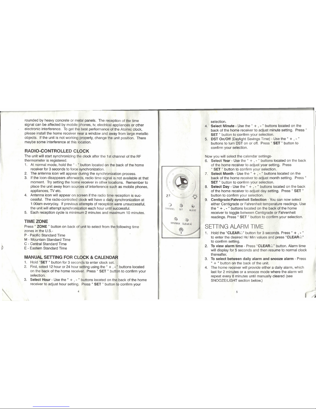
MANUAL SETTING FOR CLOCK&CALENDAR
1. Hold "SET" button for 3 seconds to enter clock set.
2. First, select 12 hour or 24 hour setting using the" + ,-" buttons located
on the back of the home receiver. Press" SET" button to confirm your
selection.
3. Select Hour - Use the" + ,- " buttons located on the back of the home
receiver to adjust hour setting. Press" SET" button to confirm your
r,
I
zz
::) :¥>
CHAlmEL SET
~
ALERT
selection.
4. Select Minute - Use the"
+ ,- "
buttons located on the
back of the home receiver to adjust minute setting. Press"
SET" button to confirm your selection.
5. DST On/Off (Daylight Savings Time) - Use the" + , - "
buttons to turn DST on or off. Press" SET" button to
confirm your selection.
Now you will select the calendar settings-
6. Select Year - Use the" + , - " buttons located on the back
of the home receiver to adjust year setting. Press
" SET" button to confirm your selection.
7. Select Month - Use the"
+ ,- "
buttons located on the
back of the home receiver to adjust month setting. Press"
SET" button to confirm your selection.
8. Select Day - Use the" + , - " buttons located on the back
of the home receiver to adjust day setting. Press" SET"
button to confirm your selection.
9. Centigrade/Fahrenheit Selection - You can now select
either Centigrade or Fahrenheit temperature readings. Use
the" + , - " buttons located on the back of the home
receiver to toggle between Centigrade or Fahrenheit
readings. Press" SET" button to confirm your selection.
SETTING ALARM TIME
1. Hold the "CLEARg" button for 3 seconds. Press" + , - "
to enter the desired Hr/ Min values and press "CLEARg"
to confirm setting.
2. To view alarm time - Press "CLEAR "button. Alarm time
will display for 5 seconds and then resume to normal clock
thereafter.
3. To select between daily alarm and snooze alarm - Press
" + "
button on the back of the unit.
4. The home receiver will provide either a daily alarm, which
last for 2 minutes or a snooze mode where the alarm will
repeat every 8 minutes until manually cleared (see
SNOOZE/LIGHT section below.)
5
Page 4

33MHz WIRELESS
ZZ
-¢-
:)
~
CHANIlEl SET
433MHz WIRELESS
'i>
ALERT
SNOOZE/ LIGHT
1. Press the SNOOZE/ LIGHT button (Zz/Iight icon button)
for an extended backlight.
2. In snooze alarm mode, press this button to trigger a
repetitive snooze alarm.
3. When normal alarm mode is selected, press the button to
turn off alarm for one day.
MAX/ MIN MEMORY SETTINGS
1. Press "MAX/ MIN" button to view the maximum values for
5 seconds. Press again to view the minimum values.
2. To clear the memory record, press "CLEAR" while the
respective values displaying on screen.
TEMPERATURE TREND INDICATOR:
In the upper right hand corner of the Home Receiver LCD
display, you will see one of 3 icons;
---" will indicate Rising temperature readings if it changes
more than 1 degree in an hour
--. will indicate Steady temperature readings
~ will indicate Falling temperatures if it is more than 1
degree in an hour.
TEMPERATURE/ HUMIDITY ALERT
Press "ALERT" to turn temperature & humidity alert on
and off.
1. Hold "ALERT" button for 3 seconds to enter the alert
setting mode. The indoor icon will flash.
2. Press" +, - " to select the between indoor temperature or
humidity to be alerted to. Press "ALERT" to confirm your
selection. The Upper pointer and the value on the LCD
display will flash, enter the desired upper limit with the
" +, - " buttons, press "ALERT" to confirm your selection
and then go to the lower limit setting.
6
3. The Lower pointer and value will flash, enter the desired lower limit with
" +, - " buttons, press "ALERT" to confirm and exit.
4. You m y enter an alert setting for the indoor temp, indoor humidity and
temper ture of the remote sensor.
5. When temperature hits the limit of your preset levels, the Upper/Lower
pointers and the temperature of the respective channel (indoor or remote
sensor) will flash and an audible alarm. Press any button on the home
receiv r to acknowledge and stop the alarm.
LOW BATTERY INDICATION
Low battery Indication is available for the home receiver and the remote
sensor. Replace the batteries and follow the setup procedure as mentioned
in this instruction manual.
MOUNTING INSTRUCTIONS
Both the Home Unit and Remote Sensor como with a table stand or they can
be wall mounted. •
Table Top-
For the home unit, simply attach the stand provided.
For the remote sensor, simply fold out the attached stand from the mounting
bracket.
Wall Mounting -
For the Home Unit - Remove the table top stand from the bottom of the unit.
Fix a screw (not included) into the desired wall and place the home unit ont
the screw using the back side hanging hole.
For the Remote Sensor - Fix two screws (not Included) into the desired
hanging location using the mounting bracket holes on the remote sensor as
a template. Ensure that the screws are placed vertically (in a straight line
up/down) along the surface and that there is proper distance between each
screw to hang the mounting bracket. Align the hanging holes of the rnounting
bracket With the two screws and place unit onto the screws.
7
I ,
Page 5

MAINTENANCE AN
CARE INSTRUCTIONS
o
Extreme temperatures, shock or areas of unusual vibration should be
avoided to prevent damage to the units.
o
Clean the units using only a soft, damp cloth to wipe. Do not use
solvents, abrasives, detergents or other strong cleaning agents. After
cleaning, wipe surfaces with dry cloth.
o
Do not submerge units in w tar or other liquids.
o
Do not subject the units to xtremely severe temperatures - DO NOT
PLACE UNITS INTO OVENS, FREEZERS or MICROWAVE UNITS.
NOTE: Opening the housing of either the Remote Sensor or the Home
Unit will invalidate your warranty. Do not attempt to repair this unit -
There are no consumer serviceable parts.
TROUBLE SHOOTING
Indoor and Outdoor temperatures do not match when
placed next to each other -
Each sensor is manufactured to be +/- 1 degree in accuracy under normal
conditions. So it is possible to have up to two degrees difference shown on
the separate temperature sensors (one could be "+1 degree" and the other
"-1 degree". Additionally, the calibration curve is different between the two
units because of the greater temperature range of the outdoor sensor.
Errors are usually noted on the extreme ends of the temperature ranges.
Base unit is not accepting remote transmissions -
The units may not be properly synchronized or the batteries may need to be
replaced. See "SETTING UP THE WIRELESS THERMOMETER" section
beginning on page 2 of the instructions for detailed instructions. With the
two units next to each other, attempt synchronization. Remember to always
place the remote sensor within the effective transmission range and away
from large metal surfaces.
What is the recommended battery type?
2 "AI\' and 2 "AM' batteries are required (not included). We recommend
using only alkaline batteries for replacements.
8
Where can I mount the remote sensor?
To get ac urate readings and to prolong the life of your sensor, we rec-
ommend lI1 t you mount it out of direct sunlight and rain. Fog and mist will
not affect the sensor, but large volumes of soaking rain may. To guard
against thl ,we recommend that you mount It under the eve of your house,
your gara or any other suitable place that will keap it out of direct sun and
rain.
FCC DISCLAIMER
Note: Thl qolpm nl h been tested and found to comply with the limits for a Class B
digital devl ,pur u ntto Part 15 of the FCC Rules. 111 limits are designed to provide
reasonabl prot euon against harmful interlerence In r Identlal installation. This
equipment nerates, uses and can radiate radio Ir qu ncy energy and, if not installed 11'1
used in accordance with the instructions, may cau 11rmful Interference to radio comrnurj
cations. However, there is no guarantee that interfer nc will not occur in a particular inst I
lation. If this equipment does cause harmful interfor nc to r dlo or television reception,
which can be determined by turning the equipm nt of 11d011,the user is encouraged to lIy
to correct the interference by one or more of the followln m sures:
• Reorient or relocate the receiving antenna.
• Increase the separation between the equipment nd r c Iv r.
Modifications not authorized by the manufacturer may void users authority to operate thl
device.
FCC 10: L5C0668TX (Transmitter)
SPECIFICATIONS
Range of temperature/humidity measurement:
Indoor temp : +32 Fto +122 F (0 C to"," 50 C)
Indoor humidity: 20% to 99% RH
Remote sensor: -4 F to +140 F (-20 C to +60 C)
Channel: max. 3 remote sensors
Temp. Alert: Indoor Temp/ Humidity and Ch 1
Transmission: max. 100 ft. (30 m) open area, RF434 MHz
Resolution: 0.1 degree for temperature
Clock: WWVB Radio-controlled
Batteries: AA x 2 pcs for main unit, AAA x 2 pes for remote sensor
9
Page 6

Name and Functions of Buttons:
Functions If button is held down
SET Enter clock & calendar
Remote Sen or/
setting
Channel Indi
lor
Temperature
Trend Indicator
+
1 step forward Alarm, Fast advance
Snooze Alarm on/ off
~a:'
p
'
Indoor
DOWN
-l
1 step backward Fast backward
Temperature
CD
Outdoor
Reading
.
Temperature
ZONE Select PST, MST, Atomic time seek
12bSB%
Reading
CST, EST
~12:315g
CLEAR/
Clear memory at Max/ Min
Alarm time setting
LCD Clock
ALARMg
display Read alarm time 5
,0/31
TU
Indoor Humidity
sec at normal mode
4!lMHIWIRIELE!oS
Reading
~
-
MAX/MIN Read maximum/ minimum
Snooze Button/
record 5 sec
Backlight
ALERT
Temp alert on/ off
Enter temp alert setting
-¢-
:)
;\)
~
CHANNEL
Select Channel 1,2,3, Delete current channel
tll~W'EL
SA
ALERT
auto scroll
">
@
MI1I'MA)( CLEAAQ
SNOOZE/
Backlight on 5 seconds,
~
I
LIGHT
Trigger snooze alarm,
stop alarm
10
11
Page 7

TAYL<9R.
leading the Way in Accuracy"
ONE YEAR LIMITED WARRANTY
(VALID IN USA ONLY)
THIS PRODUCT IS WARRANTED AGAINST DEFECTS IN MATERIALS OR WORK·
MANSHIP FOR ONE (1) YEAR FROM DATE OF ORIGINAL PURCHASE. IT DOES NOT
COVER DAMAGES OR WEAR RESULTING FROM ACCIDENT, MISUSE, ABUSE, COM-
MERCIAL USE, OR UNAUTHORIZED ADJUSTMENT AND/OR REPAIR.
SHOULD THIS PRODUCT REQUIRE SERVICE (OR REPLACEMENT AT OUR OPTION)
WHILE UNDER WARRANTY, DO NOT RETURN TO RETAILER. PLEASE PACK THE
ITEM CAREFULLY AND RETURN IT PREPAID, ALONG WITH STORE RECEIPT
SHOWING DATE OF PURCHASE AND A NOTE EXPLAINING REASON FOR RETURN
TO:
TAYLOR PRECISION PRODUCTS
2220 ENTRADA DEL SOL
LAS CRUCES, NEW MEXICO 88001
WWW.TAYLORUSA.COM
THERE ARE NO EXPRESS WARRANTIES EXCEPT AS LISTED ABOVE. THIS WARRANTY GIVES YOU SPECIFIC LEGAL
RIGHTS. AND YOU MAY HAVE OTHER RIGHTS WHICH VARY FROM STATE TO STATE.
MADE TO OUR EXACT SPECIFICATIONS IN CHINA.
© 2005 TAYLOR PRECISION PRODUCTS AND ITS AFFILIATED COMPANIES. ALL RIGHTS RESERVED. TAYLOR® AND
LEADING THE WAY IN ACCUR.ACY® ARE REGISTERED TRADEMARKS OF TAYLOR PRECISION PRODUCTS AND ITS
AFFILIATED COMPANIES. All RIGHTS RESERVED.
1434-9.06
TAYL<9R"
leading the Way in Accuracy'"
Estaci6n meteorol6gica
Funcionamiento
inelemtmo:
l
I
382
7
• .0
12~bS8~
"12:31s~
10/31
TU
4HMH'WIIIEUSS
z
:g
:)
'"
~
('I",'1,L Sfl AU!!T
Manual de instrucciones
e
informacion de garantia
1434
1
year
limited warranty
Page 8

ANTES DE COMENZAR:
Su nuevo tarrnornetro de RF (frecuencia de radio) esta construido can tecnologfa de
codiqos de seguridad aleatorios, la unidad interior captara el cooiqo aleatorio del
primer sonsor exterior y10rsqistrara en el como canal 1. Los canales 2 y 3 se
reqistraran del mismo modo en caso de usar sensores adicionales. Esta unidad
puede monitorear hasta3sensores dilerentes. (Modelo
1437,
que se vende por
separado).
• Una vez que se registra un canal, no aceptara ninqun sensor nuevo. Sin embargo,
105
canales r gistrados pueden borrarse retirando las pilas del sensor exterior0de la
unidad Interior.
Cuando cambie las pllas del sensor exterior - recuerde borrar el canal correspon-
diente de la unidad interior retirando tam bien
tas
pllas.0seleccione el canal del
sensor respectivo preslonando el boton CHANNEL (canal). Mantenga presionado el
boton CHANNEL (canal) durante 3 segundos para borrar el registro.
Cuando camble las baterias del receptor Interior - slrvase retirar las pilas de todos
los sensores exteriores. Una vez que haya cambl do las pilas del receptor interior,
vuelva a instalar las baterfas de
105
sensores, de acusrdo a la secuencia de canales
deseada. Esto asequrara que la unidad y
105
sensor s exteriores esten sincronizados
de manera adecuada.
Presione el boton Tx en la parte posterior del s nsor exterior para verilicar la
recepcion de RF.
Se recomienda probar las unidades una junto I otr para asegurarse de que
am bas, el sensor exterior y el receptor interior, 0 t n slncronizadas de manera
adecuada.
ATENCI6N: Mantenga el sensor exterior protegldo d la luz solar directa y de la
lIuvia. No10Instale sobre superficies rnetancas.
1. IMPORTANTE: Introduzca las pilas en la unidad receptora interior, y luego en el
sensor exterior.
2. Coloque la unidad interior tan cerca de la unidad exterior como sea posible. Esto
ayudara a la sincronizacion entre el sensor exterior y la unidad interior.
3. RECUERDE: Una vez que este listo para colocar su sensor exterior y su unidad
interior en el lugar, asequrese de que la distancia no este luera del ambito de trans-
miston electivo (100 pies/ 30,5 m). Algunos materiales de construccion y la ubicacion
de la unidad interior0del sensor exterior pueden alectar la calidad y el ambito de la
transmisicn. Para obtener mejores resultados, pruebe con varias posiciones.
INSTALACION DE LAS PILAS
Receptor interior:
Levante la tapa del compartimiento de las baterlas en la parte posterior de la unidad.
Instale2pilas AA de acuerdo a la polaridad que se Indica. Cierre la tapa del compar-
timiento de las pilas.
Sensor exterior:
Alloje los 4 tornillos que aseguran la tapa del compartimiento de las baterfas con un
destornillador pequeno, y retirela. Introduzca 2 pitas AM de acuerdo a la direccion de la
polaridad que se indica. Vuelva a colocar la tapa y ajuste
105
4 tornillos.
ATENCI6N: No hay piezas que neceslten servicio. Todas las preguntas0solicitudes
de servicio deberan ser dirigidas a nuestro departamento de relaciones con el con-
sumidor. (Vea la informacion de contacto en la seccion de Garantia.)
COMO CONFIGURAR LA HORA
Acerca del relo] at6mico
EI National Institute of Standard and Technology (NIST, Instltuto Nacional de Estandares y
Tecnologla) en Fort Collins, Colorado, emite la sell I hor ria (una serial de radio AM,
WWVB a 60kHz) con un precision de 1 segundo por cad a 3000 alios. La serial perrnitira
cubrir una distancia de hasta 2000 millas desde la fuente. AI igual que una tipica radio
AM, su reloj atornico no sera capaz de recibir la serial WWVB en lugares rodeados de
mucho horrniqon0paneles de metal. La recepci6n de la senal horaria puede verse
alectada por tetetonos celulares, televisores, artefactos electricos u otras interferencias
eiectronicas. Para obtener el mejor rendimiento del relo] atornico, sfrvase instalar el
receptor interior cerca de una ventana y lejos de objetos rnetalicos grandes. Si la unidad
no esta luncionando correctamente, cambie la posici6n de la misma. Puede que en esa
ubicacion haya alguna interferencia.
COMO INSTALAR EL TERMOMETRO INALAMBRICO:
Si usted tiene alguna dificultad para Instalar su sistema de terrncrnetro lnalambrico,
sirvase ponerse en contacto con Relaciones con ef consumidor,
Para la primera lnstalacion, siempre coloque las pilas PRIMERO en la unidad interior y
luego en el
(105)
sensor(es) exterior(es). (Vea la seccion INSTALACION DE LAS PILAS)
Es posible registrar un maximo de 3 unidades de sensor remoto.
La unidad incluye un sensor remoto. Para adquirir Sensores
Remotos adicionales (modelo Taylor 1437), por favor lIame al
1-877-858-0065 de lunes a viernes, de 9 a 6 PM CST (horadel
centro),0visite www.partshelf.com.
14
15
Page 9

RELOJ CONTROLADO POR RADIO
The unit wili start synchronizing the clock after the 1st channel of the RF thermometer is
registered.
1. En el modo normal, mantenga presionado durante 3 segundos el boton " - " que se
encuentra en la parte posterior del receptor interior, para provocar la sincronizacion,
2. EI icono de la antena aparecera durante el proceso de sincronlzacion.
3. Si posteriormente el leone desaparece, se debe a que la senal horaria de radio no
esta disponible en ese momento. Intente colocar el receptor interior en otras ubica-
ciones. Recuerde colocar la unidad lejos de Fuentes de interierencia tales como
teletonos celulares. artefactos, telsvisores, etc.
4. EI icono de la antena aparecera en la pantalia si la recepclon de la serial horaria de
radio es exitosa- EI reloj controlado por radio tendra una sincronizacicn diaria, todos
los dlas a la 1:00 am. Si los intenlos de recepcion anteriores fracasaron. la unidad
intentara sincronizar cada hora, hasta lener exito,
5. Cada cicio de recepcion es como minimo de 2 minutos y como maximo de 10 minutos.
ZONA HORARIA
Oprima el boton "ZONE" al respaldo de la unidad para seleccionar los siguientes husos
horarios en los EE.UU.:
P - hora estandar del Pacifico (PST)
M - hora estandar de la Montana (MST)
C - hora estandar Central (CST)
E - hora estandar del Este (EST)
CONFIGURACION MANUAL DEL RELOJ Y EL CALENDARIO
1. Mantenga presionado el boton "SET" (configurar) durante 3 segundos para ingresar
la confiquracion del reloj.
2. Primero. seleccione la confiquracion de 12 0 de 24 horas usando los botones " + ..Y
" - " ubicados en la parte posterior del receptor interior. Presione el boton "SET"
(configurar) para confirmar su seleccion.
3. Selecclon de la hora - use los bolones " + " y " - •. ubicados en la parte posterior del
receptor interior para ajustar la confiquracion de la hora. Presione el boton "SET"
(configurar) para confirmar su seleccion,
4. Sefecci6n de los minutos - use los botones •. + ..Y " - •. ubicados en la parte
posterior del receptor interior para ajustar la contiquracion de los minutos. Presione el
boton "SET" (configurar) para confirmar su seleccion.
5. DST On/Off (Hora de verano)- use los botones " + " y " - •. para encender0apagar
el DST Presione el boton "SET" (configurar) para confirmar su seleccion,
16
-,
ZZ
:) ~
CHAIII'EL 8FT
~ ~
MINIMAX
CLEAR
oQ
ALERT
Ahora saleccionara la confiquraclon del calendario:
6. Seleccion del ano - use los botones " + ..Y " - •. ubicados en la
parte posterior del receptor Interior para ajustar la conflquracion del
ano. Presione el boton "SET" (conflgurar) para confirmar su
seleccl6n.
7. seteccten del mes - use los botones " + " y •.- .. ubicados en la
parte posterior del receptor interl r p ra ajustar la configuraci6n del
meso Presione el boton "SET" (conflgurar) para confirmar su
serecclon.
8. Selecclon del dia - use los bcton
"+"
y " - •.ubicados en la
parte posterior del receptor Int rlor para ajustar la configuraci6n del
dia. Presione el boron "SET" (confl urar) para confirmar su
seleccion.
9. Seleccion de Centigrados/ F hr nh It - Ahora puede seleccionar la
lectura de la temperatura on r do CGntfgrados0en grados
Fahrenheit. Use los botonos " I
"y"
"ubicados en la parte
trasera del receptor interior p r It rn r entre lecturas en
Centigrados0en Fahrenh It. Pr Ion GI boton "SET" (configurar)
para confirmar su selecci6n.
COMO CONFIGURAR
LA
HORA DE LA
ALARMA
1. Mantenga presionado el boten "CLEAR,(\" (borrar) durante 3
segundos. Presione " + " y" "p r Ingresar los valores de horas/
minutos deseados y presion "CL ARk'" (borrar) para confirmar la
confiquracion.
2. Para ver la hora de la alarm • pr lone el boton "CLEAR "
(borrar). Aparecera la nora d I I rrna durante 5 segundos y luego.
d ahl en adelante, retom r10nor del reloj normal.
3. Para seleccionar entre ta al rm dlorla y la alarma de repetici6n -
preslone el boton " + " en I p rt posterior de la unidad.
4. EI receptor interior proporclon r y sea una alarm a diaria, que dura
2 minutos.0un modo de I rm d rapeticion, en el cual la alarma
se repetira cada 8 minutos h at qu sea detenida manualmente
(vea la seccion SNOOZE/ LIGHT (de rapeticion/ luz) a continuacI6n).
17
Page 10

433MHz WIRELESS
(~
\
~
\
zz
fHI!. "
"12:31s~
10/31
TU
433MHz WIRELESS
SNOOZE/ LIGHT (de
repeticion/
luz)
1. Presione el boton SNOOZE/ LUZ (de repeticion/ luz, boron del icono
Zz/ light) para obtener un tiempo de ilurninacion de fondo mas pro-
longado.
2. En el modo de alarma de repeticion, presione este boton para
disparar una alarm a de sonidos reiterados.
3. Cuando se selecciona el modo de alarma normal, presione el boton
para apagar la alarm a durante un dia.
CONFIGURACI6N DE MAxIMO Y MINIMO DE
MEMORIA
1. Presione el bot6n "MAXI MIN" para vel' los valores rnaxirnos durante
5 segundos. Presione nuevamente para vel' los valores minimos.
2. Para borrar el reglstro de memoria, presione "CLEAR" (borrar)
mientras se vean los valores respectivos en la pantalla.
INDICADOR DE LA TENDENCIA DE LA
TEMPERATURA:
En el anqulo superior derecho de la pantalla LCD del receptor interior,
vera uno de 3 leones:
-----" indicara lecturas de Temperatura en aumento si varia mas de un
grado en una hora
indlcara lecturas de Temperatura constante
---. indicara lecturas de Temperatura en descenso si es mas de un
grado en una hora.
ALERTA DE TEMPERATURA/ HUMEDAD
Presione ''ALERr' (alerta) para encender0apagar la alerta de tem-
peratura y humedad.
1. Mantenga presionado el boton "ALERT" (alerta) durante 3 segundos
para ingresar la contiquracion del modo de alerta. EI leone interior
destellara.
2. Presione" + "y " - " para seleccionar entre alerta de temperatura
interior0de humedad. Presione el boton "ALERT" (alerta) para con-
firmar su seleccion. EI puntero superior y el valor destellaran en la
18
pantalln I.CD: Ingrese ellimite superior deseado con 10 botones" +" y " - ". presione
''ALERT'' ( lerta) para confirmar su selecci6n y Iu 0 v ya a confiqurar el limite
inferior.
3. EI punt ro Inferior y el valor destellaran; ingro I limit Inferior deseado con los
boton • " + "y" - ": presione ''ALERr' (al rta) pnr conflrmar, y salga.
4. Pued In resar una conflquracion de alerta pI'I I mperatura interior, para la
hum d d Interior y para la temperatura del s n I' xt rlor.
5. Cuand la temperatura lIega a I limite de sus nlv I proseleccionados, los punteros
superior e inferior y la temperatura del canal r p IIvo dsstellaran (en la unidad
interior0en el sensor exterior), y se oira un I
imn,
r slone cualquier boton en el
receptor interior para aceptar el aviso y det n r I II rrna,
SENAL DE PILAS DESCARGADAS
La serial de pilas descargadas esta disponible t 111 flIfI receptor interior como para el
sensor exterior. Cambie las pilas y siga el proc dlml III d juste tal como se explica en
este manual de instrucciones.
INSTRUCCIONES DE INSTALACION
Tanto la unldad interior como el sensor exterior vi II II n un soporte de pie,0pueden
montars n la pared.
I pie que se adjunta.
u se adjunta en el soporte de
Instalacl6n n 10 p rd·
En el ca de la unld dint rtor, retire el soport d pi d I parte de abajo de la unidad.
Sujete un tornillo (que no se Incluye) a la parod d dycoloque la unidad interior
sobre el tornillo, usando I orlflcio para colgar qu II11n 10parte posterior.
En el ca 0 del sensor exterior: sujete dos tornillo
desea colgarlo, usando los orificios del soport p
patron. A ogurese de que los tornillos esten coio d v rtlcalmente (en linea recta. d
arriba h cia abajo) a 10largo de la superficie,yqu 11yuna distancia adecuada entro
cada uno de los tornillos para colgar el soport d mont je. Alinee los orificios para
colgar d I so porte de montar con los dos tornilloycoloque la unidad sobre los tornillo .
19
Page 11

INSTRUCCIONES DE MANTENIMIENTO Y CUIDADO
Las temperaturas extremas, las descargas0las areas de vibraci6n inusual deberan
evitarse para prevenir danos alas unidades.
Limpie las unidades usando solamente un pane suave y humedo para repasarlas. No
use solventes, abrasives, detergentes ni ningun otro agente de limpieza fuerte.
Despues de limpiar las superficies, sequelas con un pano seco.
No sumerja las unidades en agua ni en ninqun otro liquido.
No someta las unidades a temperaturas extremadamente duras - NO COLOQUE LAS
UNIDADES EN HORNOS, CONGELADORES ni UNIDADES DE MICROONDAS.
ATENCION: Si abre el armaz6n del sensor exterior0de la unidad interior, invalidara
su garantia. No intente reparar esta unldad - No hay piezas que necesiten servicio.
DIAGNOSTICO Y RESOLUCION DE PROBLEMAS
Las temperaturas interiores y exteriores no coinciden cuando se
colocan una junto a la otra -
Cada sensor esta fabricado para tener una tolerancia de + l- 1 grado en la precision,
bajo condiciones normales. Por10tanto es posible que haya hasta dos grados de
diferencia en los distlntos sensores de temperatura (uno puede tener "+ i grado" y el otro
-, 1 grado". Adernas, la curva de calibraci6n es diferente entre las dos unidades debido a
la mayor variaci6n de temperatura del sensor exterior. Generalmente se ven los errores
en los extremos de las variaciones de temperatura.
La unidad base no esta aceptando las transmisiones remotas -
Puede que las unidades no esten sincronizadas de manera adecuada0que sea
necesario cambiar las baterias. Vea la secci6n "COMO CONFIGURAR EL TERMOMETRO
INALAMBRICO" que comienza en la pagina 2 de las instrucciones, para obtener mas
detalles. Con las dos unidades cerca una de otra, intente la sincronizaci6n. Recuerde
colocar siempre el sensor exterior dentro del ambito de transmisi6n efectivo y lejos de
superficies rnetalicas grandes.
c.Cual es el tipo de pila recomendado?
Sus unidades requieren 2 pilas AA y 2 pilas AM (no includidas). Recomendamos que
unicamente utilice pilas alcalinas cuando las cambie.
20
c.D6nde pu do Instalar el sensor exterior?
Para obten I I oturas precisas y para extender la vida
utH
de su sensor, sugerimos que
10
instale dond: quade a salvo de la luz solar directa y de I lIuvla. La niebla y la bruma no
afectaran
1.11
nor, pero puede que si10afecten r ndes volurnenes de lIuvia. Para pro-
tegerlo do 0 l ,recomendamos que10instale bajo I I
1'0
de su casa, su cochera
0
cualquier
011'0
lugar adecuado que10mantenga I I' paro del sol directo y la lIuvia.
DESCARGO DE RESPONSABILIDAD de la FCC
Nota: Esto qulpo ha sido probado y se encontr6 qu umpte con los limites para los dis-
positlvo dlgltales Clase B, sequn la Parte 15 de10N rm de la FCC. Estos limites
estan dl
t'i
dos para proporcionar una proteccl6n I111
ere contra la interferencia perju-
dlclal en una Instalaci6n residencial. Este equipo n I' .ueypuede emitir energia de
frecuencla de radio y, si no se instala y usa sequn I
111
trucclones, puede causar una
interferencla perjudicial alas comunicaciones d ro tin, In mbargo, no hay garantia de
que no existira interferencia en una instalaci6n en I Ilioul r,51este equipo causa una
interferencia perjudicial a la recepci6n de radio 0 t I vi
16n,
que se puede determinar
apagando y encendiendo el equipo, el usuario d I r lilt nl r corregir la interferencia
mediante uno0varies de los rnetodos siguiente :
--Vuelva a orientar0ubicar la antena receptora.
-Au
mente la separaci6n entre el equipo y el rec plor,
Las modlficaclones no autorizadas por el fabric nt Ill! I n Invalidar la capacidad de los
usuarios par operar este dispositive.
NQde10do la FCC: L5C0668TX (transmisor)
ESPECIFICACIONES
Ambito de medlci6n de temperatura! humedad:
Temperatur Interior:
Humedad Interior:
Sensor ext rlor:
Canal:
Alerta:
Transmisl6n:
Resolucl6n:
Reloj:
Pilas:
de +32QF a +122QF (do
OQC
de 20% a 99% de humed d r I lIv (RH)
de -4QF a +140QF (de
-20QC 'OQC)
maximo 3 sensores exterior
Temp. interior/ HurnedadyC mol 1
maximo 100 pies (30 rn) d r blarta,
RF (frecuencia de radio) 434 Mllz
0.1 grado para temperatur
WWVB controlado por radio:
2 unidades de AA para la unldad principal, 2 unidades de AM
para el sensor exterior
21
Page 12

Nombreyfunciones de los botones:
Funciones Si el boton se mantiene
presionado
SET (configurar) -- Ingresa la configuraci6n
111(11
11I1111(I
I
delia configuraci6n del
relojydel calendario
(111111t~I
rior
y
(IUllllll/ll
+
Alarma, 1 paso adelante, Avance rapido
encendidoyapagado de
3
82'F~
alarma de repetici6n
.0
ABAJO
-I
1 paso hacia atras Retroceso rapido
12'~68%
ZONA Selecciona los horarios Busqueda de hora at6mica
PST, MST, CST, EST
"12:315'1'9
CLEAR (borrar)1
Borra el rnax' min de la Configuraci6n de hora de
R I I
C
ALARM G memoria que se muestra alarma
0/31 TU
(alarma)
Lee el tiempo de alarma
durante 5 segundos en el
411MHI WIREU,SS
modo normal
BOl6n
(Ie
unrrn
MAXIMIN
Lee los registros maximo
y
d r loilol 11/luz
minimo durante 5 segundos
d
r
11(1)
ALERT (alerta)
Encendidoyapagado de la
Ingresa la configuraci6n de
-Q.
alerta de temperatura
la alerta de temperatura
:)
~
~
CI'_I";~l
50
AlE'll
CHANNEL
Selecciona los canales 1, 2, 3,
Borra el canal actual
~
~
(canal)
avanceyretroceso autornaticos
~'t~MA,l{
ClEAA.g
SNOOZE
lIuminaci6n de fondo en
,
(de repeticionp
5 segundos, Dispara la alarma
LIGHT (Iuz) de repetici6n, detiene la alarm a
--
RECEPTOR INTERIOR
22
23
Indicador de la
tendencia de la
temperatura
Lectu ra de la
temperatura
exterior
Lectura de la
humedad interior
 Loading...