

Page 1

OPERATOR’S
MANUAL
Model 0736
Counter Top Heat Treatment
Soft Serve Freezer
Original Operating Instructions
087827-M
02/08/2018 (Original Publication)
(Updated 5/22/2019)
Page 2

Complete this page for quick reference when service is required:
Taylor distributor:___________________________________________________________
Address: _________________________________________________________________
Phone: __________________________________________________________________
Service:__________________________________________________________________
Parts: ___________________________________________________________________
Date of Installation: _________________________________________________________
Information found on the data label:
Model Number: ____________________________________________________________
Serial Number: ____________________________________________________________
Electrical Specs: Voltage__________________ Cycle__________
Phase__________________________________
Maximum Fuse Size: ______________________________________________________A
Minimum Wire Ampacity: ___________________________________________________A
Note: Continuing research results in steady improvements; therefore, informa tion in this man ual is subject to change
without notice.
Note: Only instructions originating from the factory or its authorized translation representative (s) are consider ed to be
the original set of instructions.
© 2018 Taylor Company (Updated 5/22/2019)
087827-M
Any unauthorized reproduction, disclosure, or distribution of copies by any person of any portion of this work may be
a violation of Copyright Law of the United States of America and other countries, could result in the awarding of
Statutory Damages of up to $250,000 (17 USC 504) for infringement, and may result in further civil and criminal
penalties.
All rights reserved.
Taylor Company
750 N. Blackhawk Blvd.
Rockton, IL 61072
Page 3

Section 1: To the Installer
Installer Safety ...................................................................................................1-1
Site Preparation .................................................................................................1-1
Air-Cooled Machines..........................................................................................1-2
Water Connections.............................................................................................1-2
Electrical Connections........................................................................................1-2
Electrical Hookup Installation.............................................................................1-3
Beater Rotation ..................................................................................................1-3
Refrigerant .........................................................................................................1-4
Indications for Decommissioning .......................................................................1-4
Section 2: To the Operator
Operator Information.......................................................................................... 2-1
Working Limits....................................................................................................2-1
Compressor Warranty Disclaimer ...................................................................... 2-2
Table of Contents
Section 3: Safety
Installer Information............................................................................................3-1
To Operate Safely..............................................................................................3-1
Machine Warning Labels....................................................................................3-2
Section 4: Operator Parts Identification
Main View...........................................................................................................4-1
Front - Panel ......................................................................................................4-3
Single Spout Door Assembly .............................................................................4-4
Beater Assembly................................................................................................ 4-5
Control - Main..................................................................................................... 4-6
3-Way-Valve.......................................................................................................4-7
Mix Pump Assembly...........................................................................................4-8
Tune Up Kit ........................................................................................................4-9
Brush Assembly ...............................................................................................4-10
087827-M i
Page 4

Section 5: User Interface
Symbol Definitions..............................................................................................5-2
LCD Display .......................................................................................................5-2
Indicator Icons on the Display and Buttons ........................................................5-2
Operating Screen Description ............................................................................5-3
Main Power Switch OFF.....................................................................................5-3
Main Power Switch ON ......................................................................................5-3
Heat Cycle..........................................................................................................5-3
Freezer Locks.....................................................................................................5-4
Manager's Menu.................................................................................................5-5
Manager Menu Options......................................................................................5-5
Section 6: Operating Procedures
Assembly............................................................................................................6-1
Sanitizing............................................................................................................6-7
Priming ...............................................................................................................6-8
Daily Closing Procedures ...................................................................................6-9
Daily Opening Procedures ...............................................................................6-10
Manual Brush-Cleaning....................................................................................6-10
Disassembly .....................................................................................................6-11
Adjustments......................................................................................................6-12
Section 7: Operator Checklist
During Cleaning and Sanitizing ..........................................................................7-1
Troubleshooting Bacterial Count ........................................................................7-1
Regular Maintenance Checks ............................................................................7-1
Winter Storage ...................................................................................................7-2
Section 8: Troubleshooting Guide
Section 9: Parts Replacement Schedule
Section 10: Limited Warranty on Machines
Section 11: Limited Warranty on Parts
ii 087827-M
Page 5
Section 1
!
!
The following information has been included in the
manual as safety and regulatory guidelines. For complete
installation instructions, please see the Installation
Checklist.
To the Installer
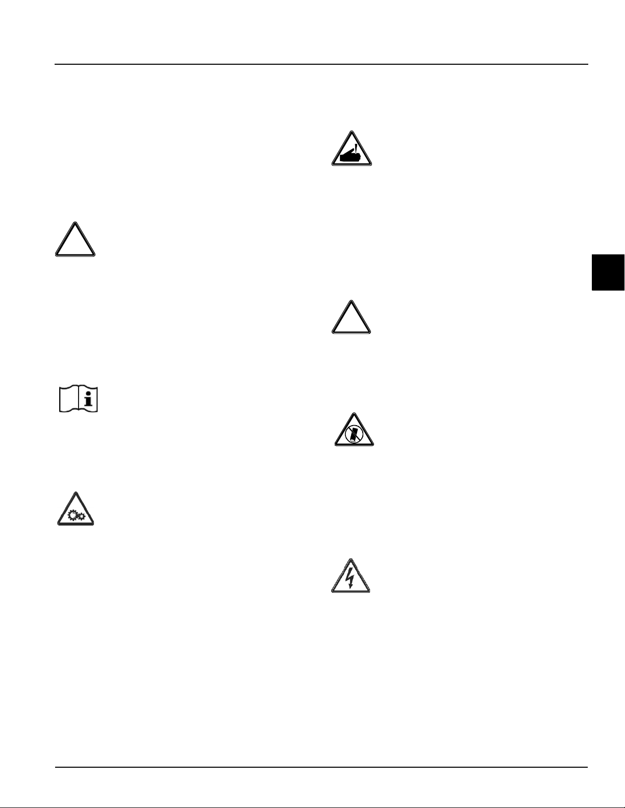
WARNING ! This machine has many sharp
edges that can cause severe injuries.
Installer Safety
IMPORTANT! In all areas of the world, the
machine should be installed in accordance with existing
local codes. Please contact your local authorities if you
have any questions.
Care should be taken to ensure that all basic safety
practices are followed during the installation and
servicing activities related to the installation and service
of Taylor machines.
• Only authorized T aylor service personnel should
perform installation and repairs on the machine.
• Authorized service personnel should consult
OSHA Standard 29CFRI910.147 or the
applicable code of the local area for the industry
standards on lockout/tagout procedures before
beginning any installation or repairs.
• Authorized service personnel must ensure that
the proper personal protective equipment (PPE)
is available and worn when required during
installation and service.
• Authorized service personnel must remove all
metal jewelry, rings, and watches before
working on electrical equipment.
Site Preparation
Review the area where the machine will be installed
before uncrating the machine. Make sure that all possible
hazards to the user and the machine have been
addressed.
WARNING! Only install this machine in a
location where its use and maintenance is restricted to
trained personnel. Failure to comply may result in
personal injury.
For Indoor Use Only: This machine is designed to
operate indoors under normal ambient temperatures of
70°F to 75°F (21°C to 24C). The freezer has
successfully performed in high ambient temperatures of
104°F (40°C) at reduced capacities.
IP Code = 23
WARNING ! This machine must NOT be
installed in an area where a water jet or hose can be
used. Never use a water jet or hose to rinse or clean this
machine. Using a water jet or hose on or around this
machine may result in the electrocution of the user or
damage to the machine.
1
DANGER! The main power supply(s) to the
machine must be disconnected prior to performing any
repairs. Failure to follow this instruction may result in
personal injury or death from electrical shock or
hazardous moving parts, as well as poor performance or
damage to the machine.
Note: All repairs must be performed by a Taylor service
technician.
To the Installer
Model 0736
CAUTION! This machine must be installed on
a level surface to avoid the hazard of tipping. Extreme
care should be taken in moving this machine for any
reason. Two or more persons are required to safely move
this machine. Failure to comply may result in personal
injury or machine damage.
Uncrate the machine and inspect it for damage. Report
any damage to your Taylor distributor.
1-1
Page 6
TO THE INSTALLER
!
!
FOLLOW YOUR LOCAL ELECTRICAL CODES.
Air-Cooled Machines
Do not obstruct air intake and discharge openings; a
minimum 6 in. (152 mm) air space is required on both
sides and 1 in. (25 mm) at rear. This will allow for
adequate air flow across the condenser. Failure to allow
adequate clearance can reduce the refrigeration capacity
of the freezer and possibly cause permanent damage to
1
the compressor.
Water Connections
Water-Cooled Machines Only
An adequate cold water supply must be provided with a
hand shutoff valve. On the underside rear of the base
pan, two 3/8 in. I.P.S. water connections for inlet and
outlet have been provided for easy hookup. Water lines
connected to the machine should have 1/2 in. (13 mm)
inside diameters. (Flexible lines are recommended, if
local codes permit.) Depending on local water conditions,
it may be advisable to install a water strainer to prevent
foreign substances from clogging the automatic water
valve. There will be only one water-in and one water-out
connection. Do not install a hand shutoff valve on the
water-out line! Water should always flow in this order:
first, through the automatic water valve; second, through
the condenser; and third, through the outlet fitting to an
open trap drain.
Electrical Connections
Each machine requires one power supply for each data
label on the machine. Check the data label(s) on the
freezer for branch circuit overcurrent protection or fuse,
circuit ampacity, and other electrical specifications. Refer
to the wiring diagram provided inside the electrical box
for proper power connections.
In the United States, this machine is intended to be
installed in accordance with the National Electrical Code
(NEC) ANSI/NFPA 70-1987. The purpose of the NEC
code is the practical safeguarding of persons and
property from hazards arising from the use of electricity.
This code contains provisions considered necessary for
safety. Compliance therewith and proper maintenance
will result in an installation essentially free from hazard!
In all other areas of the world, this machine should be
installed in accordance with the existing local codes.
Please contact your local authorities.
WARNING ! This machine must be properly
grounded! Failure to do so can result in severe personal
injury from electrical shock!
IMPORTANT! A backflow preventio n device is
required on the incoming water connection side. Please
see the applicable national, state, and local codes for
determining the proper configuration.
1-2
IMPORTANT! This machine is provided with
an equipotential grounding lug that is to be properly
attached to the rear of the frame by the authorized
installer. The installation location is marked by the
equipotential bonding symbol (5021 of IEC 60417-1) on
the removable panel and the machine’s frame.
Model 0736
To the Installer
Page 7

NOTICE!
!
• Stationary machines which are not equipped
with a power cord and a plug or another device
to disconnect the machine from the power
source must have an all-pole disconnecting
device with a contact gap of at least 0.125 in.
(3 mm) installed in the external installation.
• Machines that are permanently connected to
fixed wiring and for which leakage currents may
exceed 10 mA, particularly when disconnected
or not used for long periods, or during initial
installation, shall have protective devices to
protect against the leakage of current, such as a
GFI, installed by the authorized personnel to the
local codes.
• Supply cords used with this machine shall be
oil-resistant, sheathed flexible cable not lighter
than ordinary polychloroprene or other
equivalent synthetic elastomer-sheathed cord
(code designation 60245 IEC 57) installed with
the proper cord anchorage to relieve conductors
from strain, including twisting, at the terminals
and protect the insulation of the conductors from
abrasion.
• If the supply cord is damaged, it must be
replaced by the manufacturer, service agent, or
a similarly qualified person, in order to avoid a
hazard.
TO THE INSTALLER
Electrical Hookup Installation
CAUTION! Avoid injury.
• Make sure the machine is electrically
disconnected.
• Remove the appropriate panel and locate the
small electrical box at the base of the machine.
• Remove the factory-installed cord and strain
relief bushing.
• Route incoming permanent wiring through the
7/8 in. (22 mm) hole in base pan.
• Connect two power supply leads. Attach ground
(earth) wire to the grounding lug inside the
electrical box.
• Make sure the machine is properly grounded
before applying power.
Beater Rotation
NOTICE! Beater rotation must be
counterclockwise as viewed looking into the freezing
cylinder.
The following procedures should be performed by a
Taylor service technician.
To correct rotation on a three-phase machine,
interchange any two incoming power supply lines at
freezer main terminal block only.
1
To the Installer
To correct rotation on a single-phase machine, change
the leads inside the beater motor. (Follow the diagram
printed on the motor.)
Electrical connections are made directly to the terminal
block in the splice boxes that are mounted mid-level on
the frame channel on the sides of the freezer.
Model 0736
1-3
Page 8
TO THE INSTALLER
!
Refrigerant
CAUTION! This machine contains fluorinated
greenhouse gases (F-Gas) to provide refrigeration using
a hermetically sealed circuit or within foam insulation.
This machine's type of gas, quantity, Global Warming
1
Potential (GWP), and CO
is recorded on the unit's data-label. The refrigerant used
is generally considered non-toxic and non-flammable.
However any gas under pressure is potentially
hazardous and must be handled with caution.
NEVER fill any refrigerant cylinder completely with liquid.
Filling the cylinder to approximately 80% will allow for
normal expansion.
CAUTION! Use only approved refrigerant
listed on the machine's data-label or authorized through a
manufacturer's technical bulletin. The use of any other
refrigerant may expose users and operators to
unexpected safety hazards.
tonnes equivalent information
2
Indications for Decommissioning
IMPORTANT! If the crossed-out waste
container symbol is affixed to this product, it signifies that
this product is compliant with the EU Directive as well as
other similar legislation in effect after August 13, 20 05.
Therefore, it must be collected separately after its use is
completed, and cannot be disposed as unsorted
municipal waste.
The user is responsible for delivering the product to the
appropriate collection facility, as specified by your local
code.
Note: Even packaging materials (crates or boxes) must
be divided by type and disposed of in compliance with
Standards in force in the Country where it is used when
the machine is decommissioned.
WARNING! Refrigerant liquid sprayed onto the
skin may cause serious damage to tissue. Keep eyes
and skin protected. If refrigerant burns should occur,
flush the area immediately with cold water. If burns are
severe, apply ice packs and contact a physician
immediately.
NOTICE! Taylor reminds technicians to be
aware of government laws regarding refrigerant recovery,
recycling, and reclaiming systems. If you have any
questions regarding these laws, please contact the
factory service department.
1-4
Model 0736
To the Installer
Page 9
Section 2
To the Operator
Operator Information
The Model 0736 soft serve freezer has been carefully
engineered and manufactured to give you dependable
operation.
This machine is suitable for food mixtures heat treatment,
storage and batch, according to use allowed by law.
This machine, when properly operated and cared for, will
produce a consistent quality product. Like all mechanical
products, it will require cleaning and maintenance. A
minimum amount of care and attention is necessary if the
operating procedures outlined in this manual are followed
closely.
IMPORTANT! This manual should be read
before operating or performing any maintenance on yo ur
machine.
The Model 0736 will not eventually compensate and
correct for any errors during the setup or filling
operations. Thus, the initial assembly and priming
procedures are of extreme importance. It is strongly
recommended that personnel responsible for the
machine's operation, both assembly and disassembly, go
through these procedures together in order to be properly
trained and to prevent misunderstandings.
In the event you should require technical assistance,
please contact your local authorized Taylor Distributor.
Note: Your Taylor warranty is valid only if the parts are
authorized Taylor parts purchased from the local
authorized Taylor distributor, and only if all required
service work is provided by a Taylor service technician.
Taylor reserves the right to deny warranty claims on
machines or parts if unapproved parts or incorrect
refrigerant were installed in the machine, system
modifications were performed beyond factory
recommendations, or it is determined that the failure was
caused by abuse, misuse, neglect, or failure to follow all
operating instructions. For full details of your Taylor
warranty, please see
page 10-1 and Limited Warranty on Parts on page 11-1.
Limited Warranty on Machines on
Note: Constant research results in steady
improvements; therefore, information in this manual is
subject to change without notice
IMPORTANT! If the crossed-out waste
container symbol is affixed to this product, it signifies that
this product is compliant with the EU Directive as well as
other similar legislation in effect after August 13, 20 05.
Therefore, it must be collected separately after its use is
completed, and cannot be disposed as unsorted
municipal waste.
The user is responsible for delivering the product to the
appropriate collection facility, as specified by your local
code.
For additional information regarding applicable local
laws, please contact the municipal facility and/or local
distributor.
Working Limits
Do not use the machine with inconstant power supplies
or +/- 10% beyond the value indicated on the plate or
with the power cable damaged;
Do not use the machine in explosive atmospheres;
Do not wash the machine with high-pressure water jets
or with harmful substances;
Do not expose the machine to excessive heat or
humidity.
Do not use unbalanced mixtures and/or amounts which
do not comply with the specifications carried on the
packs.
Usage not expressly indicated in this manual is to be
considered improper and therefore must be strictly
avoided.
The manufacturer will not be held liable for direct or
indirect harm to persons or animals or damage to objects
caused by improper use of the machine.
2
To the Operator
Model 0736
2-1
Page 10

TO THE OPERATOR
Compressor Warranty Disclaimer
The refrigeration compressor on this machine is
warranted for the term stated in the Limited Warranty
section in this manual. However, due to the Montreal
Protocol and the U.S. Clean Air Act Amendments of
1990, many new refrigerants are being tested and
developed, thus seeking their way into the service
industry.
Some of these new refrigerants are being advertised as
drop-in replacements for numerous applications. It
should be noted that in the event of ordinary service to
2
this machine's refrigeration system, only the refrigerant
specified on the affixed data label should be used.
The unauthorized use of alternate refrigerants will void
your Taylor compressor warranty. It is the machine
owner's responsibility to make this fact known to any
technician he employs.
It should also be noted that Taylor does not warrant the
refrigerant used in its products. For example, if the
refrigerant is lost during the course of ordinary service to
this machine, Taylor has no obligation to either supply or
provide its replacement either at billable or unbillable
terms. Taylor does have the obligation to recommend a
suitable replacement if the original refrigerant is banned,
obsolete, or no longer available during the 5-year
warranty of the compressor.
Taylor will continue to monitor the industry and test new
alternates as they are being developed. Should a new
alternate prove, through our testing, that it would be
accepted as a drop-in replacement, then the above
disclaimer would become null and void. To find out the
current status of an alternate refrigerant as it relates to
your compressor warranty, call the local Taylor distributor
or the Taylor factory. Be prepared to provide the model/
serial number of the machine in question.
2-2
Model 0736
To the Operator
Page 11
Section 3
!
!
Safety
Installer Information
We at the Taylor Company are concerned about the
safety of the operator when he or she comes into contact
with the freezer and its parts. Taylor has gone to extreme
efforts to design and manufacture built-in safety features
to protect both you and the service technician. As an
example, warning labels have been attached to the
machine to point out safety precautions to the operator.
DANGER! Failure to adhere to the following
safety precautions may result in severe personal injury or
death. Failure to comply with these warnings may also
damage the machine and/or its components. Such
damage may require component replacement and
service repair expenses.
To Operate Safely
Failure to follow these instructions may result in severe
personal injury from hazardous moving parts.
WARNING ! This machine has many sharp
edges that can cause severe injuries.
• DO NOT put objects or fingers in the door
spout. Failure to follow this instruction may
result in contaminated product or personal injury
from blade contact.
• USE EXTREME CAUTION when removing the
beater assembly. The scraper blades are very
sharp and may cause injury.
IMPORTANT! Access to the service area of
the machine is restricted to persons having knowledge
and practical experience with the machine, in particular
as far as safety and hygiene are concerned.
3
NOTICE! DO NOT operate the machine
without reading the Operator Manual. Failure to follow
this instruction may result in machine damage, poor
machine performance, health hazards, or personal injury.
WARNING! Avoid injury.
• DO NOT allow untrained personnel to operate
this machine.
• DO NOT put objects or fingers in the door
spout.
• DO NOT operate the machine unless all service
panels and access doors are restrained with
screws.
• DO NOT remove the machine door or beater
assembly unless the control switches are in the
OFF position.
CAUTION! This machine must be installed on
a level surface to avoid the hazard of tipping. Extreme
care should be taken in moving this machine for any
reason. Two or more persons are required to safely move
this machine. Failure to comply may result in personal
injury or machine damage.
WARNING! Avoid injury.
• DO NOT operate the machine unless it is
properly grounded.
• DO NOT operate machine with larger fuses
than specified on the data label.
• All repairs must be performed by an authorized
Taylor service technician.
• The main power supplies to machine must be
disconnected prior to performing repairs.
Safety
Model 0736
3-1
Page 12
SAFETY
!
3
• For Cord-Connected Machines: Only
authorized Taylor service technicians or
licensed electricians may install a plug or
replacement cord on the machine.
• Stationary machine which are not equipped with
a power cord and a plug or another device to
disconnect the machine from the power source
must have an all-pole disconnecting device with
a contact gap of at least 0.125 in. (3 mm)
installed in the external installation.
• Machines that are permanently connected to
fixed wiring and for which leakage currents may
exceed 10 mA, particularly when disconnected
or not used for long periods, or during initial
installation, shall have protective devices to
protect against the leakage of current, such as a
GFI, installed by the authorized personnel to the
local codes.
• Supply cords used with this machine shall be
oil-resistant, sheathed flexible cable not lighter
than ordinary polychloroprene or other
equivalent synthetic elastomer-sheathed cord
(code designation 60245 IEC 57) installed with
the proper cord anchorage to relieve conductors
from strain, including twisting, at the terminals
and protect the insulation of the conductors from
abrasion.
• If the supply cord is damaged, it must be
replaced by the manufacturer, service agent, or
a similarly qualified person, in order to avoid a
hazard.
This freezer is designed to operate indoors under normal
ambient temperatures of 70F to 75F (21C to 24C).
The freezer has successfully performed in high ambient
temperatures of 104F (40C) at reduced capacity.
Do not run the machine without product. Failure to follow
this instruction can result in damage to the machine.
Noise Level: Airborne noise emission does not exceed
78 dB(A) when measured at a distance of 3.3
from the surface of the machine and at a height of 5.25 ft.
(1.6
m) from the floor.
ft. (1.0 m)
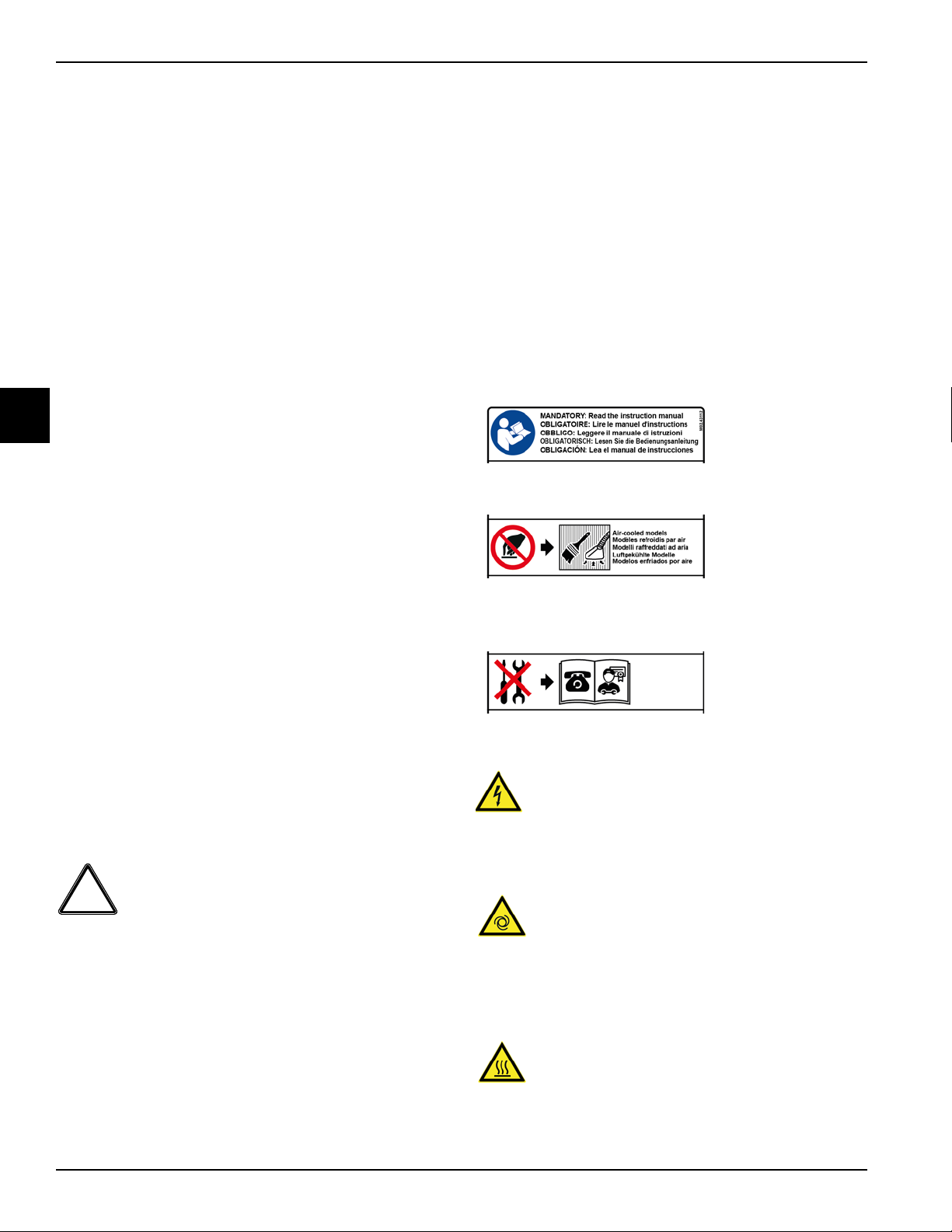
Machine Warning Labels
Rear Panel Warning Label
Do not operate the freezer without reading this
Operator’s Manual
This machine has many sharp edges that can cause
severe injuries. Do not touch with hands, clean with
brush/vacuum cleaner.
Only authorized Taylor service personnel should perform
installation and repairs on this machine.
Failure to follow these instructions may result in
electrocution. Contact your local Taylor distributor for
service.
CAUTION! This machine is designed to
maintain product temperature under 41°F (5C). Any
product being added to this machine must be below 41F
(5C). Failure to follow this instruction may result in
health hazards and poor machine performance.
Do not obstruct air intake and discharge openings: A
minimum of 6
(0
mm) in the rear is required. Install the skirt provided on
the right side of the unit. Failure to follow this instruction
may cause poor freezer performance and damage to the
machine.
3-2
in. (152 mm) on both sides, and 0 in.
Model 0736
DANGER: High Voltage inside: danger of electrocution.
Disconnect the power supply before servicing the
machine.
CAUTION: Hazardous moving parts; the machine can
start automatically. Do not operate with panels removed,
disconnect the electrical supply before servicing the
machine.
DANGER: Hot parts, risk of burns. Hot product, do not
draw during heating treatment.
Safety
Page 13
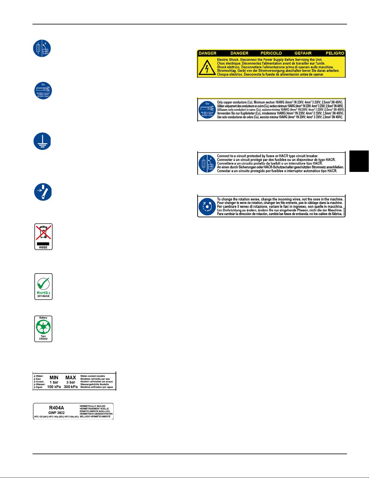
ATTENTION: Connect to a circuit protected by fuses or
HACR type circuit breaker.
ATTENTION: Only copper conductors (Cu). Minimum
2
section 10AWG (4mm
3N 400V)
ATTENTION: This equipment must be properly
grounded! Failure to do so can result in severe personal
injury from electrical shock!
1N 230V; 4mm2 3 230V; 2.5mm2
SAFETY
Electrical Box Warning Label
DANGER: High voltage inside, danger of electrocution.
Disconnect the Power Supply Before Servicing the Unit.
ATTENTION: Only copper conductors (Cu). Minimum
2
section 10AWG (4mm
3N 400V).
ATTENTION: Connect to a circuit protected by fuses or
HACR type circuit breaker.
1N 230V; 4mm2 3 230V; 2.5mm2
3
ATTENTION: Disconnect the power supply before
servicing the machine.
For decommissioning, comply with the standards in force
in the country where it is used.
This machine is RoHS2 compliant.
Battery type CR2032 inside. For decommissioning,
comply with the standards in force in the country where it
is used.
To correct rotation on a three-phase machine,
interchange any two incoming power lines at the machine
main terminal block only.
To correct rotation on a single-phase machine, change
the leads inside the beater motor. (Follow diagram
printed on motor.)
Water pressure limits (for water-cooled models only).
Use only R404A refrigerant that conforms to the AHRI
Standard 700 specification.
Safety
Model 0736
3-3
Page 14

SAFETY
Hot Parts/Type of Glycol Warning Label
DANGER: Hot parts, risk of burns. Use only
recommended Glycol with the described dilution.
Equipotential Point Label
Carry out an equipotential bonding, using the screw
3
placed below the frame of the machine.
Lifting Point Label
Lift equipment hooking points. Position the lifting
equipment only in the relevant points.
3-4
Model 0736
Safety
Page 15
Section 4
1
2
3
9
4
8
5
6
7
10
13
12
11
14
18
15
20
19
26
17
16
21
22
25
24
23
25
27
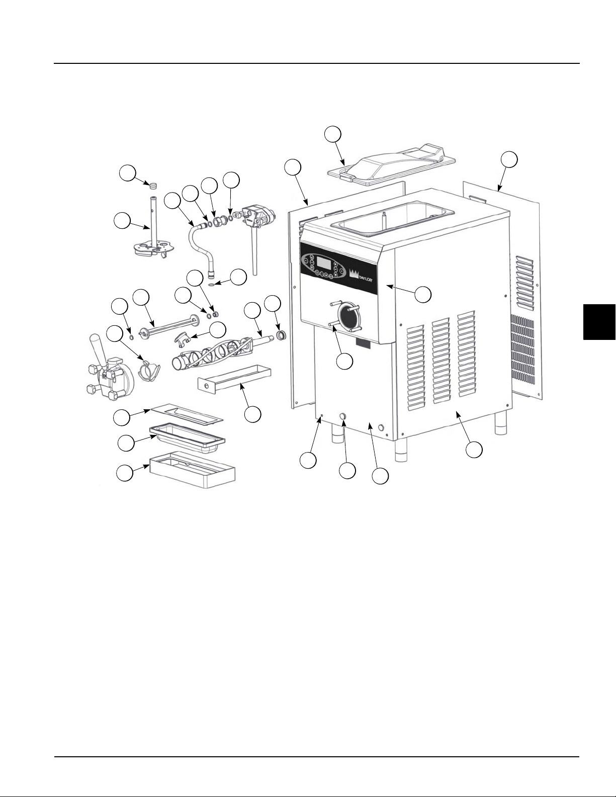
Main View
Operator Parts Identification
4
Figure 4-1
Operator Parts Identification
Model 0736
4-1
Page 16

OPERATOR PARTS IDENTIFICATION
Main - View continued
Item Description Part No.
1 Panel-Side-Left 087715
2 Cover-Hopper 087716
3 Panel-Rear 087717
4 Panel-Side-Right 087718
5 Panel-Front-Lower 087719
Screw - Mounting - Collar 087720
6
Screw-Panel 087721
7
Stud-Nose Cone 087722
8
Panel-Front-Upper 087723
9
Pan-Drip 087724
10
Shelf-Tray-Drip 087725
11
Tray-Drip 087726
4
12
Shield-Splash 087727
13
Item Description Part No.
Beater-Auger 087728
14
Baffle-Door 087729
15
O-ring-Baffle 087730
16
Bushing-Baffle 087731
17
Blade-Scraper 087732
18
Beater-2-Liter 087733
19
Seal-Beater-Drive Shaft 087734
20
Agitator-Hopper 087735
21
Cap-Agitator 087875
22
Tube-Feed 087737
23
Coupling-Feed Tube 087738
24
O-ring-Feed Tube 087762
25
Valve-Check- Duckbill-Pump 087742
26
O-ring - Baffle - Door 087745
27
4-2
Model 0736
Operator Parts Identification
Page 17

Front - Panel
1
2
3
4
5
OPERATOR PARTS IDENTIFICATION
Item Description Part No.
1 Panel - Front - Lower 087719
2 Guide - Drip - Pan 087713
3 Shield - Splash 087727
4
Figure 4-2
Item Description Part No.
4 Tray - Drip 087726
5 Shelf - Tray - Drip 087725
Operator Parts Identification
Model 0736
4-3
Page 18
OPERATOR PARTS IDENTIFICATION
3
4
7
5
6
8
9
10
12
11
1
2
x2
x4
Single Spout Door Assembly
4
Item Description Part No.
1 Handle-Draw-Black 087740
2 Valve-Draw 087741
3 O-ring-Draw Valve 087743
Figure 4-3
Item Description Part No
7 Nut-Stud-Door 087748
8 O-ring-Handle Pin 087749
9 Screw-Adjustmt-Handle 087750
4 O-ring-Door-Large 087744
5 Pin-Draw Handle-SS 087746
6 Door-Freezer 087747
4-4
Model 0736
10 Spacer-Screw-Adjustmt 087751
11 Handle-Body 087752
12 O-ring-Handle-Body 087753
Operator Parts Identification
Page 19
Beater Assembly
1
2
3
4
5
6
7
8
OPERATOR PARTS IDENTIFICATION
Item Description Part No.
1 Baffle - Door 087729
2 O-ring - Baffle 087730
3 Bearing - Door - Baffle 087731
4 O-ring - Baffle - Door 087745
Figure 4-4
Item Description Part No.
5 Blade - Scraper 087732
6 Beater - Auger 087728
7 Beater - 2 - Liter 87733
8 Seal - Beater - Drive - Shaft 087734
4
Operator Parts Identification
Model 0736
4-5
Page 20
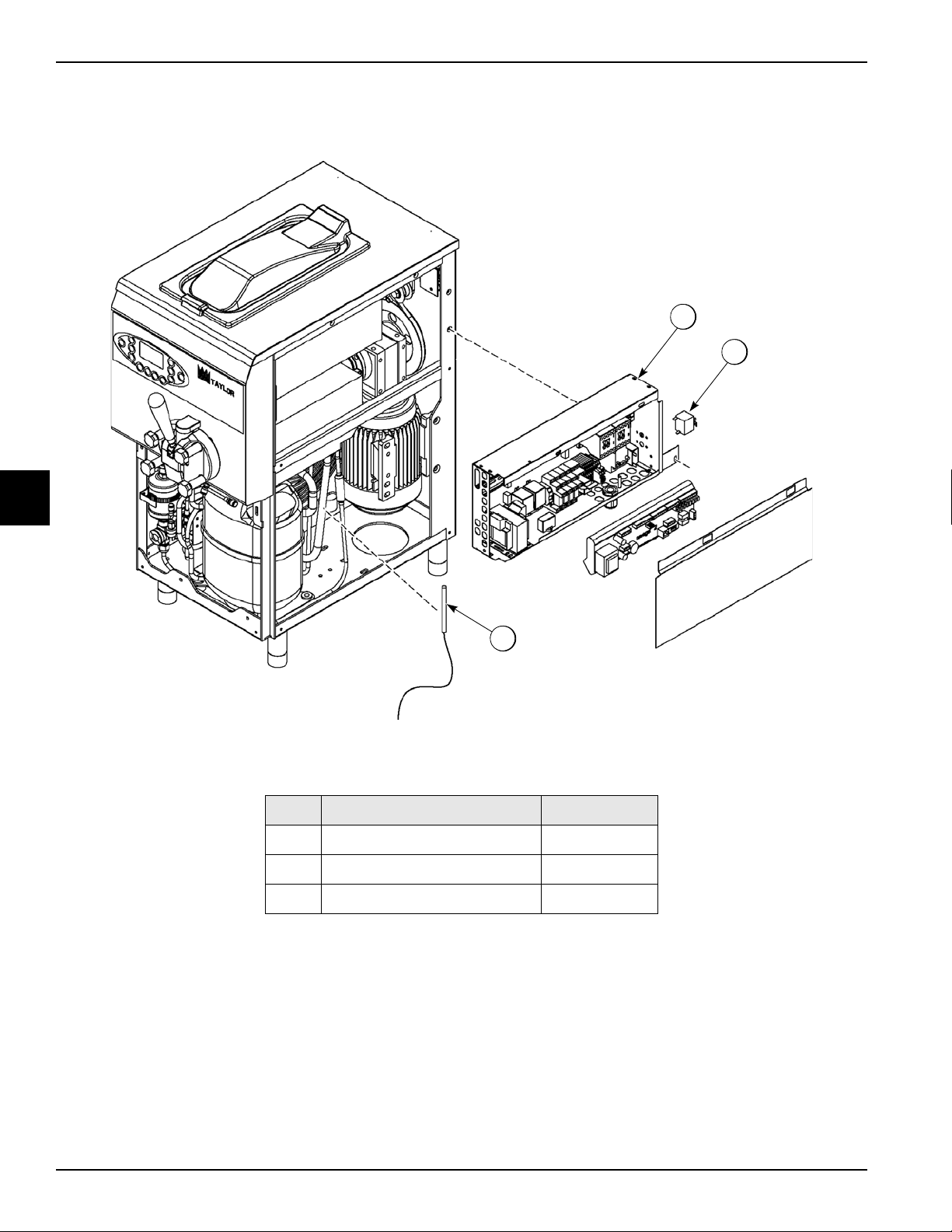
OPERATOR PARTS IDENTIFICATION
1
2
3
Control - Main
4
Figure 4-5
Item Description Part No
1 Thermostat 087948
2 Control - Main 087948-58
3 Probe - Thermistor 087957
4-6
Model 0736
Operator Parts Identification
Page 21

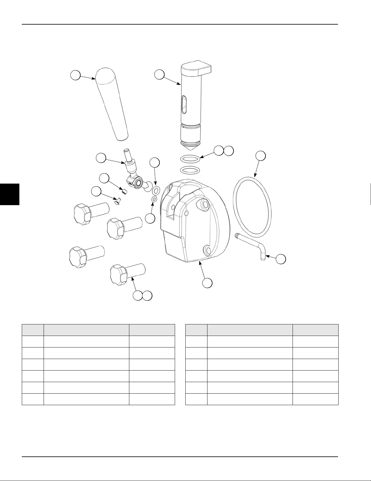
3-Way-Valve
2
4
3
2
1
1
5
2
6
x5
OPERATOR PARTS IDENTIFICATION
Item Description Part No.
1 Hose - Rubber 5/16” ID x 9/16” OD 047340F60
2 Adaptor - 1/4MP x 5/16 Barb-BR 047326F
3 Bracket - Valve 087947
Figure 4-6
Item Description Part No.
4 Valve - 3 Way 087946
5 Elbow - 1/4 MP x 5/16 Barb -Brass 047327F
6 Clamp - Hose 35/64 - Stepless EA 087730
4
Operator Parts Identification
Model 0736
4-7
Page 22

OPERATOR PARTS IDENTIFICATION
1
2
3
4
5
6
7
8
10
9
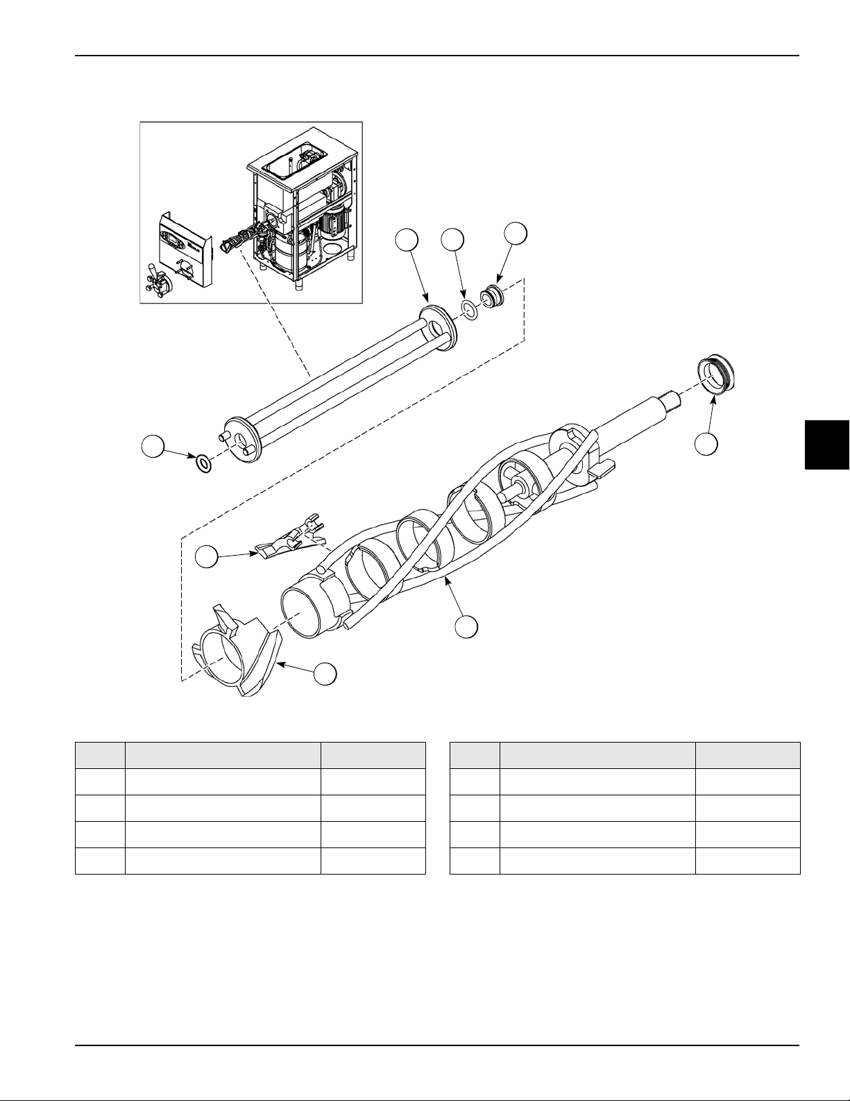
Mix Pump Assembly
4
Item Description Part No.
1 Cover-Pump 087754
2 O-ring Pump Body 087755
Figure 4-7
Item Description Part No.
6 Valve-Pump 087765
7 Spring-Regulator 087761
3 Gears-Mix Pump Set 087756
4 Body-Pump 087758
5 O-ring-Pump 087759
4-8
Model 0736
8 O-ring-Feed Tube 087762
9 Tube-Regulator 087763
10 Nut-Stud-Pump 087764
Operator Parts Identification
Page 23

Tune Up Kit
1
OPERATOR PARTS IDENTIFICATION
Item Description Part No.
1 Kit-Tune Up *0736* 087774
2 O-ring-DEL Tube/Regulator 087762
3 O-ring-Pump 087759
4
Figure 4-8
Item Description Part No.
9 Bearing-Door-Baffle 087731
10 Cap-Agitator 087875
11 O-ring-Handle-Pin 087749
4 O-ring-Baffle 087730
5 O-ring-Draw-Valve 087743
6 Valve-Check-Duckbill-Pump 087742
7 Valve-Pump 087765
8 Seal-Beater-Drive-Shaft 087734
Operator Parts Identification
Model 0736
12 O-ring-Handle-Body 087753
13 O-ring-Door-Small 087745
14 O-ring-Pump-Body 087755
15 O-ring-Door-Large 087744
16 Tool-O-ring Removal-Freezer 048260-F
4-9
Page 24

OPERATOR PARTS IDENTIFICATION
2
3
4
1
Brush Assembly
4
Figure 4-9
4-10
Item Description Part No
1 Kit-Brush *0736* 087805
2 Brush-Hopper 087805-A
3 Brush-Mix Inlet 087805-B
4 Brush-Drive Hub 087805-C
Model 0736
Operator Parts Identification
Page 25

Section 5
The number indicates the consistency of the product
and can be adjusted from 60 to 250. High numbers
correspond to high consistencies, low numbers
correspond to lower consistencies.
The ice cream cone icon flashes to indicate that the
consistency of the product in the barrel is not ready
for dispensing. When the consistency approaches
10% of the programmed consistency value, the
icon remains ON, indicating that the product is
ready to be delivered.
Graphics indicate
the machine mode.
The icon
indicates if
the beater
is ON.
Graphics
indicate the
maximum,
minimum, or
reserve level
of the mix in
the hopper.
The icon
indicates if
the agitator
in the hopper
is ON.
The handle in the
upper position
indicates that the
draw valve is
closed.
The handle in the
lower position
indicates that the
draw valve is
open or not completely closed.
The temperature of the product in
the hopper is displayed at the
top-right of the display. By
pressing the C button you can
display (in sequence) the
temperature in the barrel (BRL),
the glycol fluid temperature, and
the CTS safety-probe
temperature.
User Interface
5
User Interface
Figure 5-1
Model 0736
5-1
Page 26

USER INTERFACE
= MANAGER'S MENU
= UP ARROW
= DOWN ARROW
= OK
= CANCEL
= AUTO
= HEAT CYCLE
= STANDBY
= WASH
= OPTIONS
= STOP
= MIX HOPPER
Symbol Definitions
To better communicate in the international area, symbols
have replaced words on many of our operator switches,
function, and fault indicators. Your Taylor machine is
designed with these international symbols.
The following chart identifies the symbol definition.
5
LCD Display
The display is located on the front control panel. The
display is used to show menu options and notifies the
operator if a fault is detected. The display indicates also
the temperature of the mix in the hopper, in the barrel and
its level.
Indicator Icons on the Display and Buttons
MIX LOW—When the MIX LOW icon is displayed, the
mix hopper has a low supply of mix and should be refilled
as soon as possible.
MIX OUT—When the MIX OUT icon is displayed (the
LEVEL message is displayed), the mix hopper has been
almost completely exhausted and has an insufficient
supply of the mix to operate the freezer. At this time, the
Auto mode is locked out and the freezer will be placed in
Standby mode. To initiate the refrigeration system, add
mix to the mix hopper. The freezer will automatically
begin operation.
BRUSH-CLEAN COUNTER—When the BRUSH CLEAN
COUNTER display has counted down to "1," the machine
must be disassembled and brush-cleaned within
24
hours.
Figure 5-2
Manager's Menu Button
The Manager's Menu is used to enter the operator
function displays. To access the Menu, press the SEL
button.
Up ARROW Button
If active, it increases the value of the set.
Down ARROW Button
If active, it decreases the value of the set.
OK Button
If active, it confirm the value of the set.
C Button
If active, it deletes the set value or exits the menu. In
Auto mode, the C button displays the temperature of the
barrel, the CTS system temperature and the glycol
temperature.
Auto Button
The Auto button will illuminate when it is pressed. This
indicates that the refrigeration system has been
activated. In the Auto mode, the Wash or Standby
functions are automatically canceled.
5-2
Model 0736
User Interface
Page 27

USER INTERFACE
Heat Button
When the Heat mode button is illuminated, the freezer is
in the process of a Heat cycle.
Standby Button
The Standby feature maintains product temperatures in
both the hopper and the barrel below 40°F (4.4°C). This
feature is useful during long "No Sale" periods to prevent
overbeating and product breakdown.
When Standby is selected, the Standby button
illuminates, indicating the Standby feature has been
activated. In the Standby mode, the Wash and Auto
functions are automatically canceled.
To resume normal operation, press the Auto button.
When the machine cycles off, the product in the barrel
will be at serving viscosity.
Wash Button
The Wash button will illuminate when pressed. This
indicates beater motor operation.
Option Button
The Option button, if pressed simultaneously with the
Auto button and held down for at least 5 seconds, allows
the access to the adjustment menu for the product
consistency and for the agitator motor cycle adjustment
during the Auto mode.
Operating Screen Description
When the machine is powered, the control system will
initialize to perform a system check. The screen will
display the Taylor logo for a few seconds.
Main Power Switch OFF
When the main power switch is OFF, the following screen
is displayed in international date sequence (DD/MM/YY).
Figure 5-3
Main Power Switch ON
When the main power switch is placed in the ON
position, the control panel buttons become operative and
the following screen is displayed:
:
5
The Option button, if pressed simultaneously with the
Standby button and held down at least 5 seconds, allows
access to the adjustment menu for the product
temperature and for the agitator motor cycle adjustment
during the Standby mode.
STOP Button
The STOP button will illuminate when pressed. This
indicates the machine is off.
Mix Hopper Agitator
When the Mix Hopper button is illuminated, the agitator in
the hopper is on.
Keypad Lock
To lock the control panel and prevent accidental use
(ex: self-service applications) press and hold the OK
button for at least 5 seconds; the closed padlock icon
appears on the left side of the display to indicate that
each function pushbutton is disabled.
To unlock the control panel, press and hold the OK button
for at least 5 seconds.
Figure 5-4
Heat Cycle
The Heat Cycle button on the control panel is illuminated
throughout the Heat Treatment Cycle.
• Do not attempt to draw product or disassemble the
machine during the Heat cycle. The product is hot
and under extreme pressure.
In the Heat cycle, the mix temperature in the hopper and
barrel must be raised to 156°F (69°C) within 90
When the heating phase is complete, the freezer goes
into the holding phase of the cycle. The holding phase
will keep the temperature above 156°F (69°C) for a
minutes.
User Interface
Model 0736
5-3
Page 28

USER INTERFACE
minimum of 45 minutes.
The final phase of the Heat Treatment Cycle is the
cooling phase. The freezer must cool the mix below 41°F
(5°C) within 120 minutes.
When the entire Heat cycle has been completed, the
machine will enter the Storage mode. The machine can
be placed in Auto or left in Storage.
To comply with health codes, heat treatment system
freezers must complete a Heat Treatment Cycle daily
and must be disassembled and brush-cleaned according
to the frequency specified by your federal, State, or local
regulatory agencies. Please consult your governing
health codes to determine the maximum number of days
allowed between brush-clean cycles.
Brush-cleaning is the normal disassembly and cleaning
procedure found in the Operator’s Manual. Failure to
follow these guidelines will cause the control to lock the
freezer out of the Auto mode.
Always comply with local health codes for the maximum
number of days allowed between brush-clean cycles.
Freezer Locks
5
There are two types of freezer lock conditions that can
occur: hard lock or soft lock:
• Hard lock requires the machine be disassembled
and brush-cleaned.
• Soft lock can be corrected by either disassembling
and brush-cleaning the machine or by starting
another Heat Treatment Cycle.
Hard Lock
The machine will hard lock if either the brush-clean timer
has elapsed or if a thermistor failure (freezing cylinder or
hopper) occurs during the Heat cycle.
The following screen will be displayed if a brush-clean
cycle time has occurred:
If the machine has hard locked and an attempt is made to
enter the Auto mode, the machine will remain in the
Standby mode and will not allow any dispensing.
The WASHING REQUIRED message will remain on the
display until the brush-clean requirements are fulfilled. To
reset the hard lock, turn the main power switch OFF for at
least 5 minutes and disassemble the freezer for the
cleaning procedure.
Soft Lock
When a Heat Treatment Cycle has not been initiated
within the last 24 hours, a soft lock failure will occur. A
soft lock allows the operator to correct the cause of the
soft lock. The operator has the option of either starting
another Heat cycle or brush-clean the machine. When a
soft lock occurs, the machine will go into Standby mode.
The message FREEZER LOCKED - HEAT TREAT
REQUIRED is displayed on the screen. The reason for
soft lock is indicated in the Lockout History in the
Manager's Menu (SEL button).
When the reason for the soft lock has been corrected,
selecting Heat Cycle button initiates a Heat cycle
immediately.
A soft lock can also occur any time during operation
when the hopper or barrel temperature rises above 59°F
(15°C), the temperature rises and remains above 45°F
(7°C) for more than 1 hour, or the temperature rises and
remains above 41°F (5°C) for more than 4 hours.
If a product over temperature condition occurs during
operation, the message FREEZER LOCKED - HEAT
TREAT. REQUIRED is displayed on the screen.
When one of these messages appears, automatic freezer
operation cannot take place until the freezer is
disassembled and brush-cleaned, or has completed a
Heat Treatment Cycle.
Note: A record of Heat Cycle Data and Lockout History
can be found in the Manager's Menu (SEL button).
5-4
Figure 5-5
Model 0736
User Interface
Page 29

USER INTERFACE
Manager's Menu
The Manager's Menu is used to enter the operator
function displays. To access the Menu, press the SEL
button.
In the Menu program, the Arrow buttons, the OK button,
and the C button will function as menu buttons.
• Up Arrow—increases the value above the cursor and
is used to scroll upward in text displays.
• Down Arrow—decreases the value above the cursor
and is used to scroll downward in text displays.
• OK—Confirms the selected value.
• C—Deletes the selected value.
There is a 1-minute time-out in effect during the
Manager's Menu. While in the Manager's Menu, if no
activity occurs within a 1-minute period, the display will
exit to the main screen.
Note: The machine will continue operation in the mode
it was in when the Menu was selected. However, the
control buttons will not be lit and are non-functional when
the Manager's Menu is displayed.
Manager Menu Options
Press the SEL button to enter in the Manager's Menu.
Press the Arrow buttons to move up or down through the
Menu. Select a Menu option by pressing the OK button.
The following menu options are listed in the Manager's
Menu.
• SERVINGS COUNTER
• SET CLOCK
• AUTO HEAT TIME
• AUTO START TIME
• AUTO STANDBY TIME
• EVENT HISTORY
• LOCKOUT HISTORY
• HEAT CYCLE SUMMARY
• HEAT CYCLE DATA
• SYSTEM INFORMATION
• LANGUAGE
Exit the Menu program by touching the STOP or
C
button.
Servings Counter
The SERVINGS COUNTER option is used to check the
total and partial number of servings dispensed from the
machine. The partial counter will automatically reset to
zero when the machine is cleaned; you can also reset
this counter manually by selecting the OK button to
confirm the operation.
5
Figure 5-6
The total counter cannot be reset by the operator.
Figure 5-7
User Interface
Model 0736
5-5
Page 30

USER INTERFACE
Set Clock
The SET CLOCK option allows the manager to adjust the
control clock, date, and time. The date and time may only
be changed after the freezer has been manually cleaned,
but before it has been placed in Auto or Standby mode.
The following message will be displayed if the Set Clock
option is selected:
Figure 5-8
To change the data or time, select the SET CLOCK
option in the menu. The hour setting is automatically
selected; press the Arrow buttons to increase or
decrease the value. Press the OK button to confirm the
value and to advance to the next entry. Enter the correct
5
minutes, day, month, and year then press the OK button
to save and return to the main menu.
Auto Heat Time
The AUTO HEAT TIME screen allows the manager to set
the time of day in which the Heat Treatment Cycle will
start if the machine is in Auto or Standby mode.
Auto Start Time
The AUTO START TIME option allows the manager to
set the time of day at which the machine automatically
enters the Auto mode from the Standby/Storage mode.
The machine must be in the Standby/Storage mode
without a freezer lock condition in order to Auto start at
the programmable time. The Auto Start Time can also be
disabled and require starting the Auto mode manually.
Figure 5-10
The hour setting is automatically selected; press the
Arrow buttons to increase or decrease the value. Press
the OK button to confirm the value and to advance to the
next entry. Enter the correct minutes and press the OK
button to save and return to the main menu.
Note: Disable the AUTO START TIME by selecting "- -"
in "hours" settings.
Auto Standby Time
The AUTO STANDBY TIME option allows the manager to
set the time of day at which the machine automatically
enters the Standby mode from the Auto mode. This
allows power savings during slow sales. The Auto
Standby Time can also be disabled and require starting
the Standby mode manually.
Figure 5-9
The hour setting is automatically selected; press the
Arrow buttons to increase or decrease the value. Press
the OK button to confirm the value and to advance to the
next entry. Enter the correct minutes and press the OK
button to save and return to the main menu.
5-6
Model 0736
Figure 5-11
User Interface
Page 31

USER INTERFACE
The hour setting is automatically selected; press the
Arrow buttons to increase or decrease the value. Press
the OK button to confirm the value and to advance to the
next entry. Enter the correct minutes and press the OK
button to save and return to the Main Menu.
Note: Disable the AUTO STANDBY TIME by selecting
"- -" in "hours" settings.
Event History
The EVENT HISTORY screen will display up to 200
events. The most recent event is displayed on screen 1.
The data and time description is displayed on each
screen. Press Arrow buttons to display the next screen;
press the OK or C button to return to the main menu.
Listed below are the variable messages which will
appear, along with an explanation of the corrective
action.
DOOR O.—(DOOR OPEN) A product door is not in place
or it is loose.
FLU.LEV.—(ALARM—INSUFFICIENT FLUID LEVEL)
The fluid level is too low to operate; switch off the
machine. Call your Taylor service technician.
TEV INT.—(ALARM—PROBE TEV INTERRUPTED) The
hopper thermistor is open; switch off the machine. Call
your Taylor service technician.
TEV S.C.—(ALARM—PROBE TEV SHORT CIRC.) The
hopper thermistor has shorted; switch off the machine.
Call your Taylor service technician.
TEC INT.—(ALARM—PROBE TEC INTERRUPTED)
The barrel thermistor is open; switch off the machine.
Call your Taylor service technician.
TEC S.C.—(ALARM—PROBE TEC SHORT CIRC.) The
barrel thermistor has shorted; switch off the machine.
Call your Taylor service technician.
TEF S.C.—(ALARM—PROBE TEF SHORT CIRC.) The
fluid thermistor has shorted; switch off the machine. Call
your Taylor service technician.
CTS INT.—(ALARM—PROBE CTS INTERRUPTED)
The CTS thermistor is open; switch off the machine. Call
your Taylor service technician.
CTS S.C.—(ALARM—PROBE CTS SHORT CIRC.) The
CTS thermistor has shorted; switch off the machine. Call
your Taylor service technician.
THERMAL—(ALARM—THERMAL OVERLOAD) Press
the STOP button and wait 5 minutes for the machine to
cool. Restart in AUTO. If the alarm continues, call your
Taylor service technician.
PHASES—(ALARM—PHASES L2-L3 SWITCHED)
Press the STOP button and switch off the machine. Call
your Taylor service technician.
PHASES/N—(ALARM—SWITCH PHASE / NEUTRAL)
Press the STOP button and switch off the machine. Call
your Taylor service technician.
MICRO TA—(ALARM—NO CURRENT SIGNAL OR
DEFECTIVE TRANSFORMER) Press the STOP button
and switch off the machine. Call your Taylor service
technician.
DEV. KO—(ALARM—DEVICE KO!) Switch off the
machine. Call your Taylor service technician.
COM. KO—(ALARM—COMMUNICATION ERROR!)
Switch off the machine. Call your Taylor service
technician.
TIME OUT—(ALARM—BATCH TIME OUT) The
compressor run time exceeded the 120-minute timer.
Replace the scraper blades during the next brush
cleaning. If that does not resolve the fault, call your
Taylor service technician.
5
TEF INT.—(ALARM—PROBE TEF INTERRUPTED) The
fluid thermistor is open; switch off the machine. Call your
Taylor service technician.
User Interface
Model 0736
5-7
Page 32

USER INTERFACE
Lockout History
The LOCKOUT HISTORY screen displays a history of
the last 200 soft locks, hard locks and aborted Heat
cycles. The most recent lockout is displayed on screen 1.
The data and time description is displayed on each
screen. Press the Arrow buttons to display the next
screen; press OK or C button to return to the main menu.
The following variable messages which will appear, along
with an explanation of the corrective action:
Faults occurring while in Heat mode
LOCK HT—(HEAT MODE FAILURE) The maximum
allowable heat mode time exceeded 90 minutes.
LOCK CL—(COOL MODE FAILURE) The maximum
allowable cool mode time exceeded 120 minutes.
LOCK TT—(TOTAL TIME FAILURE) The maximum
allowable total heat treatment time exceeded 4 hours.
LOCK OP—(OPERATOR ABORT) The operator has
aborted the heat treatment cycle.
WARN. PS—(POWER FAIL IN H/C) A power failure
occurred during the heat treatment cycle.
WASHING REQUIRED—(BRUSH CLEAN TIMEOUT)
5
The total days in operation exceeded the brush clean
cycle setting.
Heat Cycle Summary
The HEAT CYCLE SUMMARY screen displays the hours
since the last Heat cycle, the hours since the product
temperature was above 150°F (65.6°C), and the number
of Heat cycles completed since the last brush-clean date.
Figure 5-12
Heat Cycle Data
The HEAT CYCLE DATA screen contains a record up to
400 Heat Treatments Cycles. The most recent Heat cycle
is displayed on screen 1. The data and time description is
displayed on each screen. Press Arrow buttons to display
the next screen; press C button to return to the main
menu.
Faults Occurring While in Auto mode
HP 5C 4H—The mix temperature in the hopper was
above 41°F (5°C) more than four hours.
BR 5C 4H—The mix temperature in the barrel was above
41°F (5°C) more than four hours.
HP 5C PF—The mix temperature in the hopper was
above 41°F (5°C) more than four hours following a power
failure.
BR 5C PF—The mix temperature in the barrel was above
41°F (5°C) more than four hours following a power
failure.
HP 7C 1H—The mix temperature in the hopper was
above 45°F (7°C) more than one hour.
BR 7C 1H—The mix temperature in the barrel was above
45°F (7°C) more than one hour.
HP 15C—The mix temperature in the hopper exceeded
59°F (15°C).
BR 15C—The mix temperature in the barrel exceeded
59°F (15°C).
Figure 5-13
Select the desired cycle and press the OK button to open
the detail screen. The screen displays the month and day
of the Heat cycle, the start time and end time. The middle
line indicates if an alarm or a lockout occurred during the
Heat cycle.
The remaining lines indicate the following:
• HEAT—Total time for the hopper (H) and barrel (B) to
reach 150 °F (65.6°C).
• OVER—Total time the hopper (H) and barrel (B)
temperature was above 150 °F (65.6°C).
5-8
Model 0736
User Interface
Page 33

USER INTERFACE
• COOL—Total time the hopper (H) and barrel (B)
temperature was above 41°F (5°C) during the cool
phase.
• PEAK—Highest temperature reading for the hopper
(H) and barrel (B) during the Heat Treatment Cycle.
Figure 5-14
Press the Down Arrow button to advance to the next
Heat cycle stored.
System Information
The SYSTEM INFORMATION screen displays the
machine’s part number, the LCD version, and the main
board’s software release date.
Press the C button to return to the main menu.
Language
The LANGUAGE screen allows the manager to set the
language of the display. Press the Arrow buttons to scroll
through the list of available languages; press the OK
button to confirm your choice. Press the OK button again
to save and exit to the menu.
Figure 5-16
5
User Interface
Figure 5-15
Model 0736
5-9
Page 34

USER INTERFACE
Notes:
5
5-10
Model 0736
User Interface
Page 35

Section 6
Operating Procedures
This machine stores mix in a hopper. It has a 2.1 qt.
(2.0 L) capacity barrel with a single-spout door.
We begin our instructions at the point where we enter the
store in the morning and find the parts disassembled and
laid out to air dry from the previous night's cleaning.
These opening procedures will show you how to
assemble these parts into the freezer, sanitize them, and
prime the freezer with fresh mix in preparation to serve
your first portion. If you are disassembling the machine
for the first time or need information to get to this staring
point in our instructions, see “Disassembly” on page
and start there.
6-11
Assembly
Note: When lubricating parts, use an approved food
grade lubricant (example: Taylor Lube). MAKE SURE
THE MACHINE IS DISCONNECTED! Failure to follow
this instruction may result in severe personal injury from
hazardous moving parts.
Beater Assembly
1. Attach the scraper blade to the beater assembly at
the locations as indicated. Repeat this step for the
others scraper blades.
2. Insert the beater auger on the beater body; Make
sure the lip of the auger is inserted in the slot of the
beater.
Figure 6-2
3. Lightly lubricate both sides of the beater driveshaft
seal. Slide this seal up to the stop. Do not lubricate
the square end.
\
6
Operating Procedures
Figure 6-1
Figure 6-3
4. Holding the beater securely, slide the beater
assembly into the freezer cylinder while lightly
compressing the scraper blades. Slide the beater into
the barrel and engage the square end firmly into the
drive coupling.
Model 736
6-1
Page 36

OPERATING PROCEDURES
Figure 6-4
Freezer Door Assembly
1. Place the door O-ring into the groove on the back of
the freezer door.
3. Lightly lubricate the inside of the top of the freezer
door valve cavity.
Figure 6-7
6
Figure 6-5
2. Slide the two O-rings into the grooves on the draw
valve and lubricate them.
Note: If the draw valve is inserted with the flat
surface facing the user, this will prevent the machine
from operating.
4. Insert the draw valve from the top, with the flat part
facing toward the machine.
6-2
Figure 6-6
Model 736
Figure 6-8
Operating Procedures
Page 37

5. Insert the counter-beater on the rear pin on the
freezer door and rotate it until the pins align with the
holes in the door. Place the counter-beater O-ring
into the groove on rear pin of the freezer door.
Figure 6-9
6. Insert the plastic bushing into the back of the
counter-beater. Place the O-ring into the groove of
the bushing.
OPERATING PROCEDURES
Figure 6-11
8. With the door seated on the freezer studs, install the
handscrews. Tighten them equally in a crisscross
pattern to ensure the door is secure.
Figure 6-10
7. With both hands, hold the sides of the freezer door
and insert the counter-beater into the center of the
beater assembly. The counter-beater rear bushing
must fit securely onto the pin at rear of the beater.
6
Figure 6-12
9. Insert the handle body O-ring handle in the goove in
the side of draw handle body.
Figure 6-13
Operating Procedures
Model 736
6-3
Page 38

OPERATING PROCEDURES
10. Position the draw handle with the adjustment screw
facing down. Slide the ball of the draw handle into the
slot of the draw valve. Secure the draw handle to the
door using the pivot pin. Place the handle pin O-ring
in the groove at the end of the pin.
Figure 6-14
11. Slide the drip pan into the hole in the front panel.
Mix Pump Assembly
1. Inspect the rubber and plastic pump parts. The
O-rings must be in 100% good condition for the pump
and entire machine to operate properly. They cannot
properly serve their intended function if nicks, cuts, or
holes in the material are present.
Inspect the plastic pump parts for cracks, wear, and
delamination of plastic.
Replace any worn, damaged, or inoperable parts
immediately.
2. Place the pump body O-ring in the groove.
6
Figure 6-15
12. Install the front drip tray bracket, rubber drip tray, and
splash shield under the door spout.
Figure 6-16
Figure 6-17
3. Place the two pump O-rings into the groove on the
back of the pump body and lubricate them.
Figure 6-18
6-4
Model 736
Operating Procedures
Page 39

OPERATING PROCEDURES
4. Lubricate the interior surfaces of the pump body
(the rear wall, pin, and bushing).
Figure 6-19
5. Insert the drive gear on the bushing; check that the
upper face of the gear is flush with the rim of the
pump body.
7. Install the pump cover on the pump body studs.
Note: The pump cover holes have different
diameters to prevent incorrect assembly.
Install the handscrews and tighten them equally to
make sure the pump is closed.
Figure 6-22
Note: Do not lubricate the graduated holes.
8. Slide the regulator O-ring into the groove on the
liquid regulator and lubricate.
Figure 6-20
6. Insert the driven gear on the pin; check that the upper
face of the gear is flush with the rim of the pump
body. Lightly lubricate the flat faces of both gears.
6
Figure 6-23
9. Insert the regulator spring into the liquid regulator
seat. Insert the pump valve into the spring so the
larger part is out of the spring.
Operating Procedures
Figure 6-21
Model 736
6-5
Page 40

OPERATING PROCEDURES
Feed Tube Assembly
1. Slide one feed tube O-ring into the groove on the
bushing and lubricate.
Figure 6-24
10. Insert the liquid regulator into the hole located on the
bottom of the pump cover, aligning the notch with the
retaining pin. Rotate to lock in place.
6
Figure 6-25
11. The regulator can be adjusted to six available
positions to achieve the desired overrun.
Figure 6-27
Note: Make sure the valve is properly seated in the
tube. Do not lubricate the duck-bill valve.
2. Slide the additional feed tube O-rings into the
grooves on the feed-tube and lubricate them.
Insert the duck bill valve into the feed tube until it
slides in place in the groove.
Figure 6-28
6-6
Figure 6-26
Model 736
Operating Procedures
Page 41

OPERATING PROCEDURES
3. Place the feed tube coupling onto the feed tube until
it reaches the stop position.
Sanitizing
1. Prepare an approved 100 PPM sanitizing solution
®
(example: 2-1/2 gal. [9.5 L] of Kay-5
[7.6 liters] of Stera-Sheen®). Use warm water and
follow the manufacturer's specifications.
2. Pour the sanitizing solution over all the parts in the
bottom of the mix hopper and allow it to flow into the
barrel.
or 2 gal.
Figure 6-29
4. Lay the hopper agitator, the feed tube and the
complete pump in the bottom of the mix hopper for
sanitizing.
Figure 6-31
Note: You have just sanitized the mix hopper and
parts; therefore, make sure your hands are clean and
sanitized before performing the following steps.
3. While the solution is flowing into the barrel, take
particular care to brush-clean the mix-level sensing
probe on the bottom of the hopper, mix hopper,
complete air/mix pump, feed tube, and hopper
agitator.
4. Brush the exposed sides of the hopper.
5. Place the main power switch in the ON position.
6. Press the Wash button. This will cause the sanitizing
solution in the barrel to be agitated. Wait at least 5
minutes before proceeding with these instructions.
Press STOP button.
7. Install the pump assembly at the rear of the mix
hopper. To position the pump on the support, align
the drive hole in the pump body with the driveshaft.
Secure the pump in place by rotating the pump
assembly until the hook engages with the pivot pin.
Do not attach the feed tube to the pump.
6
Operating Procedures
Figure 6-30
Model 736
6-7
Page 42

OPERATING PROCEDURES
4. Install the assembled feed tube in the mix inlet in the
bottom of the hopper. Connect the other end of the
feed tube to the outlet of the pump. Secure the feed
tube in place by rotating the feed tube coupling.
Make sure that the regulator tube is set to the correct
position for the desired overrun.
Figure 6-32
8. Press the Wash button. This will cause the sanitizing
solution to be circulated through the pump. Wait at
least 1 minute before proceeding to the next steps.
Open the draw valve and draw off the sanitizing
solution from barrel and hopper.
9. Press the STOP button and close the draw valve.
Important! The machine must not be placed in Auto
mode until all sanitizing solution has been removed
from the barrel and proper priming procedures have
been completed. Failure to follow this instruction may
result in damage to the barrel, the beater and/or the
door.
6
Note: Make sure your hands are clean and
sanitized before proceeding to the next step.
Note: Make sure your hands are clean and
sanitized before proceeding to the next step.
Figure 6-33
10. Place the hopper agitator on the agitator driveshaft
housing. Rest the feed tube against the inside wall of
the hopper.
Priming
Note: Use only fresh mix when priming the freezer.
1. Place an empty pail beneath the door spout. Pour
2
gal. (8.0 L) of fresh mix into the mix hopper and
allow it to flow into the barrel.
To remove all sanitizing solution, open the draw valve
until fresh mix flows from the door spout, then close
the draw valve.
Important! Failure to remove all sanitizing solution
may result in damage to the barrel.
2. Allow the mix to continue filling the freezing cylinder.
3. Press the Wash button to prime the pump. Verify that
the mix is flowing out of the pump for a few seconds.
Press STOP button.
Figure 6-34
6-8
Model 736
Operating Procedures
Page 43

OPERATING PROCEDURES
5. Press the Wash button. Open and close the draw
valve six times to complete the priming procedure.
Note: Use extreme caution when opening the draw
valve because the mix is pressurized.
6. Press the Auto button.
7. Fill the hopper with fresh mix and place the cover in
its correct position.
Daily Closing Procedures
This procedure must be performed once daily!
The function of the Heat Treatment Cycle is to destroy
bacteria by raising the temperature of the mix in the
barrel and the hopper to a specified temperature for a
specified period of time, and then bringing the
temperature back down low enough to retard spoilage.
The Heat Treatment Cycle will start at the time
designated in the Auto Heat Time.
Important! The level of mix in the mix hopper must be
enough to cover the level probe.
Note: If the BRUSH CLEAN COUNTER display has
counted down to one day, do not add mix. The machine
must be disassembled and brush-cleaned within 24
hours.
The freezer must be in Auto (Auto button illuminated) or
in Standby/Storage mode (Standby button illuminated)
before the Heat cycle may be started.
1. Remove the hopper cover.
Important! Make sure your hands are clean and
sanitized before performing the following steps.
2. Remove the hopper agitator from the mix hopper.
3. Take the agitator and the hopper cover to the sink for
further cleaning and sanitizing.
4. Rinse these parts in cool, clean water.
5. Prepare a small amount of an approved 100 PPM
®
sanitizing solution (example: Kay-5
Stera-Sheen®). Use warm water and follow the
manufacturer's specifications. Brush-clean the
agitator and the hopper cover.
6. Install the agitator back onto the agitator driveshaft
housing. Replace the hopper cover.
or
Important! Make sure the agitator is installed and the
switch is in the Auto or Standby/Storage mode or the
machine will not have a successful Heat cycle.
7. Return to the freezer with a small amount of cleaning
solution. Dip the door-spout brush into the cleaning
solution and brush-clean the door spout and the
bottom of the draw valve.
Note: To ensure sanitary conditions are maintained,
brush each item for a total 60 seconds, repeatedly
dipping the brush in cleaning solution.
8. Remove, clean, and reinstall the drip tray and splash
shield.
9. Using a clean, sanitized towel, wipe down the freezer
door, front panel, the area around the bottom of the
freezer door, and any other areas that shows a
buildup of either moisture or food substance.
The Heat cycle will start when the clock on the
machine reaches the Auto Heat Time setting in the
Manager's Menu.
There are three phases of the Heat cycle; heating,
holding, and cooling. Each phase has a time limit. If
any one of three phases fail to reach the proper
temperatures within the time limit, the cycle will
automatically abort and return to the Standby/
Storage mode.
A failure message will appear on the LCD to inform
the operator that the machine did not successfully
complete the Heat Treatment Cycle. The product
may not be safe to serve. The freezer will be locked
out (soft lock) of the Auto mode. The operator will be
given the option of selecting the Heat Cycle button,
which will begin a new Heat cycle or pressing the
main power switch, which will place the freezer in the
Off mode to allow a brush-clean of the machine.
Note: Once the Heat cycle has started, it cannot be
interrupted. The Heat cycle will take a maximum of
4 hours to complete with a full hopper.
Important! Do not attempt to draw product or
disassemble the machine during Heat cycle. The product
is hot and under extreme pressure.
When the Heat cycle is complete, the machine will
enter the Storage mode.
6
Operating Procedures
Model 736
6-9
Page 44

OPERATING PROCEDURES
ALWAYS FOLLOW LOCAL HEALTH CODES.
Daily Opening Procedures
Before performing the opening procedures, check the
display panel for any error messages. If a fault has been
detected, investigate the cause before proceeding with
the opening procedures.
1. Prepare a small amount of an approved 100 PPM
®
sanitizing solution (example: Kay-5
®
Sheen
manufacturer's specifications.
Note: T o ensure sanitary conditions are mainta ined,
brush-clean each item for a total of 60 seconds,
repeatedly dipping the brush in sanitizing solution.
2. Return to the freezer with a small amount of cleaning
solution. Dip the door-spout brush into the cleaning
solution and brush-clean the door spout and the
bottom of the draw valve.
3. Using a clean, sanitized towel, wipe down the freezer
door, front panel, the area around the bottom of the
freezer door, and any other areas that shows a
buildup of either moisture or food substance. Install
the front drip tray and splash shield.
). Use warm water and follow the
or Stera-
Draining Product From the Barrel
1. With a pail beneath the door spout, open the draw
valve to release the barrel pressure. Press the Wash
button and wait for a few seconds.
2. Press the STOP button. Disconnect and remove the
feed tube, pump, and hopper agitator.
3. Press the Wash button. Drain the product from the
barrel and the mix hopper.
4. When the flow of product stops, press the STOP
button. Close the draw valve. Properly dispose of the
mix.
Rinsing
Note: Do not brush-clean the mix inlet hole while
the machine is in the Wash mode.
1. Pour 2 gal. (8.0 L) of cool, clean water into the mix
hopper. Using the hopper brush, scrub the mix
hopper, mix-level sensing probe, and the outside of
the agitator driveshaft housing. Brush-clean the mix
inlet hole.
4. When ready to resume normal operation, press the
Auto button.
Note: This procedure should be performed 15
6
minutes prior to serving product, if this is not
pre-programmed.
Manual Brush-Cleaning
These procedures must be completed according to the
frequency specified by your federal, state, or local
regulatory agencies. Please consult your governing food
code to determine the maximum number of days allowed
between brush-clean cycles.
!
To disassemble these machine, the following items will
be needed:
• Two cleaning and sanitizing pails
• Sanitizer/Cleaner
• Cleaning brushes
• Single-service towels
Figure 6-35
2. With a pail beneath the door spout, open the draw
valve and press the Wash button.
3. Drain all the rinse water through the door spout.
Close the draw valve and press the STOP button.
4. Repeat this procedure using clean, warm water, until
the water being discharged is clear.
6-10
Model 736
Operating Procedures
Page 45

OPERATING PROCEDURES
Hopper Cleaning
1. Prepare an approved 100 PPM sanitizing solution
(example: 2-1/2 gal. [9.5 L] of Kay-5
[7.6 L] of Stera-Sheen®). Use warm water and follow
the manufacturer's specifications.
2. Pour the solution into the hopper and allow it to flow
into the barrel.
Note: Do not brush-clean the mix inlet hole while
the machine is in the Wash mode.
3. Using the hopper brush, clean the mix hopper,
mix-level sensing probe, and the outside of the
agitator driveshaft housing. Brush-clean the mix inlet
hole.
4. Press the Wash button. This will cause the cleaning
solution in the barrel to come in contact with all areas
of the barrel.
5. Place an empty pail beneath the door spout.
6. Open the draw valve on the freezer door and draw off
all the solution.
7. Once the cleaning solution stops flowing from the
door spout, close the draw valve and press the STOP
button.
®
or 2 gal.
Disassembly
Note: Failure to remove the parts specified in the
following brush-cleaning and lubrication procedures will
result in damage to the machine. These parts must be
removed within the maximum number of days allowed
between brush-clean cycles or the machine will hardlock
and will not operate.
WARNING! Make sure the power switch is in
the OFF position! Failure to follow this instruction may
result in severe personal injury to fingers or hands from
hazardous moving parts.
1. Remove the handscrews, freezer door, beater,
scraper blades, and the driveshaft seal from the
barrel.
2. Remove the scraper blades and the beater head
from the beater.
3. Remove the driveshaft seal from the beater.
4. Disassemble the pump. Remove the liquid regulator
tube with the pump valve, the spring, and the O-ring.
Remove the cover, the gears, and the O-rings.
Remove the feed tube, feed tube coupling, duck-bill
valve, and the O-rings.
Note: Never use any tool to remove the gears from
the pump body.
5. Disassemble the freezer door. Remove the door
O-ring, pivot pin, draw valve, draw handle,
counter-beater with bushings, and O-rings.
6. Remove the front drip shelf, drip tray, and splash
shield.
7. Remove the drip pan.
8. Take all parts to the sink for cleaning.
Note: If the drip pan is filled with an excessive
amount of mix, it is an indication that the driveshaft
seal should be replaced or properly lubricated.
Brush-Cleaning
1. Prepare an approved 100 PPM sanitizing solution
®
(example: 2-1/2 gal [9.5 L] of Kay-5
®
of Stera-Sheen
manufacturer's specifications.
2. Thoroughly brush-clean all disassembled parts in the
cleaning solution, making sure all lubricant and mix
film is removed. Make sure to brush all surfaces and
holes, especially the holes in the pump components
and the draw valve hole in the freezer door.
Place the parts on a clean, dry surface to air-dry
overnight.
3. Return to the freezer with a small amount of cleaning
solution. Using a brush, clean the driveshaft opening
at the back of the freezing cylinder.
4. Using the brush, clean the mix pump drive hub
opening in the rear wall of the mix hopper.
5. Wipe all exterior surfaces of the freezer with a clean,
sanitized towel.
). Use warm water and follow the
or 2 gal. [7.6 L]
6
Operating Procedures
Model 736
6-11
Page 46

OPERATING PROCEDURES
Adjustments
For best performance carefully read the following
instructions before proceeding.
Consistency Adjustment
1. With the machine filled with fresh mix, press the Auto
button to start the freezing cycle.
Note: The freezing cycle will start with the last
programmed consistency valu e.
2. Press the Auto and Option buttons simultaneously for
a few seconds until the adjustment menu appears on
the display.
Figure 6-36
3. The first menu item allows the operator to adjust the
consistency of the product by setting a number on a
scale from 60 to 250. Low numbers correspond to
low product consistency, high numbers correspond to
6
high product consistency.
Press the Up Arrow button to increase the value;
press the Down Arrow button to decrease the value.
Hopper Temperature Adjustment in Auto Mode
1. With a machine loaded with fresh mix, press the
Auto button to start with the freezing cycle.
2. Press the Auto and Option buttons simultaneously for
a few seconds until the adjustment menu appears on
the display.
Figure 6-38
3. The first menu item allows the operator to adjust the
consistency of the product. Touch the OK button to
confirm the displayed value and switch to the next
entry.
4. Subsequent parameters allow the operator to change
the temperature of the mix in the hopper during the
Auto mode between 32°F (0°C) and 41°F (5°C).
5. Press the Up Arrow button to increase the
temperature; press the Down Arrow button to
decrease the temperature.
Figure 6-37
4. Press OK button to confirm the new selected value.
Press C button to erase the new value.
5. Press the OK button to confirm the other menu items
and exit the menu by saving the changes.
6-12
Model 736
Figure 6-39
6. Press OK button to confirm the new selected value.
Press C button to erase the new value.
7. Press the OK button to confirm the other menu items
and exit the menu.
8. Press the OK button to confirm the other menu items
and exit the menu by saving the changes.
Operating Procedures
Page 47

OPERATING PROCEDURES
Hopper Agitation Adjustment in Auto Mode
1. With the machine filled with fresh mix, press the Auto
button to start the freezing cycle.
2. Press the Auto and Option buttons simultaneously for
a few seconds until the adjustment menu appears on
the display.
Figure 6-40
3. The first menu item allows you to adjust the
consistency of the product. Press the OK button to
confirm the displayed value and switch to the next
entry.
4. Subsequent parameters allow the operator to change
the operating times (MIXING ON) and pause
(MIXING OFF) of the hopper agitator motor during
the Auto mode.
Hopper Temperature Adjustment in Standby Mode
1. With the machine filled with a fresh mix, press the
Standby button.
2. Press the Standby and Option buttons
simultaneously for a few seconds until the
adjustment menu appears on the display.
Figure 6-42
3. The first menu item allows the operator to change the
temperature of the mix in the hopper during the
Standby mode between 32°F (0°C) and 41°F (5°C).
Figure 6-41
5. Press the Up Arrow button to increase the time;
press the Down Arrow button to decrease the time.
6. Press OK button to confirm the new selected values.
Press C button to erase the new values.
6
Figure 6-43
4. Press the Up Arrow button to increase the
temperature; press the Down Arrow button to
decrease the temperature.
5. Press OK button to confirm the new selected value.
Press C button to erase the new value.
6. Press the OK button to confirm the other menu items
and exit the menu by saving the changes.
Operating Procedures
Model 736
6-13
Page 48

OPERATING PROCEDURES
Hopper Agitation Adjustment in Standby Mode
1. With the machine filled with fresh mix, press the
Standby button.
2. Press the Standby and Option buttons
simultaneously for a few seconds until the adjustment
menu appears on the display.
Figure 6-44
3. The first menu item allows you to adjust the
temperature of the product in Standby mode. Press
the OK button to confirm the displayed value and
switch to the next entry.
4. Subsequent parameters allow the operator to change
the operating times (MIXING ON) and pause
(MIXING OFF) of the hopper agitator motor during
the Standby mode.
Figure 6-45
5. Press the Up Arrow button to increase the time;
press the Down Arrow button to decrease the time.
6. Press the OK button to confirm the new selected
value. Press C button to erase the new value.
7. Press the OK button to confirm the other menu items
and exit the menu by saving the changes.
6
6-14
Model 736
Operating Procedures
Page 49

Section 7
ALWAYS FOLLOW LOCAL HEALTH CODES.
!
Operator Checklist
During Cleaning and Sanitizing
!
Cleaning and sanitizing schedules are governed by
federal, state, or local regulatory agencies, and must
be followed accordingly. If the machine has a Standby
mode, it must not be used instead of proper cleaning
and sanitizing procedures and frequencies set forth by
the ruling health authority.
The following checkpoints should be stressed during
the cleaning and sanitizing operations:
IMPORTANT! Cleaning and sanitizing must be
performed daily.
Troubleshooting Bacterial Count
Thoroughly clean and sanitize the machine
regularly, including complete disassembly and
brush-cleaning.
Use all the brushes supplied for thorough
cleaning. The brushes are specially designed to
reach all mix passageways.
Use the middle-size brush to clean the mix inlet
hole which extends from the mix hopper down to
the rear of the barrel.
Use the smaller brush to clean the drive hub
opening in the rear wall of the mix hopper. Use a
generous amount of cleaning solution on the
brush.
Use the smaller, white bristle brush to clean the
mix inlet hole that extends from the mix hopper
down to the rear of the freezing cylinder.
Use the black bristle brush to thoroughly clean the
shell bearing located at the rear of the freezing
cylinder. Use a generous amount of cleaning
solution on the brush.
If local health codes permit the use of rerun,
make sure the mix rerun is stored in a sanitized,
covered stainless steel container and is used the
following day. Do not prime the machine with
rerun. When using rerun, skim the foam and
discard it. Mix the rerun with fresh mix in a ratio of
50:50 during the day's operation.
On a designated day of the week, run the mix as
low as feasible and discard after closing. This will
break the rerun cycle and reduce the possibility of
high bacteria and coliform counts.
Properly prepare the cleaning and sanitizing
solutions. Read and follow label directions
carefully. Too strong of a solution may damage
the parts, and too weak of a solution will not do an
adequate job of cleaning or sanitizing.
The temperature of the mix in the mix hopper and
walk-in cooler should be below 40F (4.4C).
Discard remaining mix from the freezer during
"Cleaning Procedures."
Regular Maintenance Checks
Replace scraper blades that are nicked or
damaged. Before installing the beater assembly,
make sure the scraper blades are properly
attached to the beater.
Using a screwdriver and a cloth towel, keep the
rear shell bearing and the female hex drive socket
clean and free of lubricant and mix deposits.
Dispose of O-rings or seals if they are worn, torn,
or fit too loosely, and replace them with new ones.
Follow all lubricating procedures as outlined in
“Assembly” on page 6-1.
If your machine is air-cooled, check the condenser
for dirt and lint. A dirty condenser will reduce the
efficiency and capacity of the machine.
Condensers should be cleaned monthly with a
soft brush. Never use screwdrivers or other metal
probes to clean between the fins.
7
Operator Checklist
Model 0736
7-1
Page 50

OPERATOR CHECKLIST
Note: For machines equipped with an air filter, it will be
necessary to vacuum clean the filters on a monthly
schedule.
WARNING! Always disconnect electrical
power prior to cleaning the condenser. Failure to follow
this instruction may result in electrocution.
If your machine is equipped with an auxiliary
refrigeration system, check the auxiliary
condenser for accumulation of dirt and lint. A dirty
condenser will reduce the refrigeration capacity of
the mix hopper. Condensers must be cleaned
monthly with a soft brush. Never use
screwdrivers or other metal probes to clean
between the fins. Failure to comply may result in
electrocution.
If your machine is water-cooled, check the water
lines for kinks or leaks. Kinks can occur when the
machine is moved back and forth for cleaning or
maintenance purposes. Deteriorated or cracked
water lines should be replaced only by a Taylor
service technician.
Winter Storage
It is recommended that a Taylor service technician
perform winter storage draining, to ensure all water has
been removed. This will guard against freezing and
rupturing of the components.
If the place of business is to be closed during the winter
months, it is important to protect the freezer by following
certain precautions, particularly if the building is subject
to freezing conditions.
Important! On water-cooled freezers, disconnect the
water supply . Relieve pressure on the spring in th e water
valve. Use air pressure on the outlet side to blow out any
water remaining in the condenser. This is extremely
important. Failure to follow this procedure may cause
severe and costly damage to the refrigeration system.
Your local Taylor distributor can perform this service for
you.
• Disconnect the freezer from the main power source
to prevent possible electrical damage.
• Wrap detachable parts of the freezer (such as the
beater assembly and freezer door) and place them in
a protected, dry place. Rubber trim parts and gaskets
can be protected by wrapping them with
moisture-proof paper.
• All parts should be thoroughly cleaned of dried mix or
lubrication accumulations, which can attract mice
and other vermin.
7
7-2
Model 0736
Operator Checklist
Page 51

Section 8
Troubleshooting Guide
Table 8-1
Problem Probable Cause Remedy
1. Soft lock message
appears on display.
2. Hard lock message
appears on display.
3. No control panel
functions with machine
connected to the power
supply.
4. Machine makes a
squealing noise
5. No product is being
dispensed
a. More than 24 hours since the last
Heat cycle.
b. The freezer was not in the Auto or
Standby mode when the Heat
cycle was programmed to start.
c. The hopper agitator is not installed. c. The hopper agitator must be cleaned
d. There was a power failure. d. Check the Event History fault
a. Brush-cleaning interval exceeded. a. The freezer must be disassembled
a. Circuit breaker OFF or blown fuse. a. Turn the breaker ON or replace the
b. Blown main board fuses. b. Call a service technician.
a. Starved barrel. a. Remove, clean, and re-install the
a. Low on mix. The LEVEL message
is displayed.
b. Machine not in Auto mode. b. Select Auto and allow machine to
c. Beater motor is off during over
temperature. The message
appears on the display.
a. The freezer must go through a Heat
cycle every 24 hours. The freezer
must now be disassembled and
brush-cleaned or placed in a Heat
cycle.
b. The freezer must be in the Auto or
Standby mode. The freezer must now
be disassembled and brush-cleaned
or placed in a Heat cycle.
and installed before starting the Heat
cycle. The freezer must now be
disassembled and brush cleaned or
placed in a Heat cycle.
messages. Disassemble and
brush-clean, or initiate a Heat
Treatment Cycle.
and brush-cleaned within 24 hours
when the counter indicates one day
remaining.
fuse.
pump.
b. Check, and if necessary, change the
position of the regulator tube on
position for greater liquid flow (turn it
to the left).
a. Add mix to the hopper.
cycle off before drawing product.
c. Press the STOP button and wait
5 minutes. Restart the machine in
Auto mode.
Page
Ref.
- - -
5-3 and
6-10
5-3 and
6-10
5-7
6-10
- - -
- - -
6-4
- - -
8
- - -
5-2
5-2
Troubleshooting Guide
Model 0736
8-1
Page 52

TROUBLESHOOTING GUIDE
Problem Probable Cause Remedy
6. The product is too soft. a. The viscosity control is set too
warm.
b. The scraper blades are worn. b. Replace the scraper blades with new
7. The product is too thick. a. The viscosity control is set too
cold.
b. Barrel not primed correctly. b. Drain the barrel and prime the
c. Mix pump incorrectly assembled. c. Follow assembly procedures
d. Mix pump incorrectly set. d. Check and if necessary, change the
e. Butterfat is in the pump. e. Disassemble, clean, and re-install the
8. The mix in the hopper is
too warm.
9. The mix in the hopper is
too cold.
10. Mix low and mix out
probes are not
functioning.
11. Product is collecting on
top of the freezer door.
12. Excessive mix leakage
from the bottom of door
spout.
13. Excessive mix leakage
into the long drip pan.
a. Hopper cover is not in position. a. Clean and sanitize the hopper cover
b. The agitator is not installed. b. Clean and sanitize the agitator and
c. The hopper temperature control is
set too warm.
d. Defective thermistor probe. d. Call a service technician.
a. The hopper temperature control is
set too cold.
b. Defective Thermistor probe. b. Call a service technician.
a. Milk stone or foam buildup in the
hopper.
a. The top O-ring on draw valve is
improperly lubricated or worn.
a. Bottom O-ring on the draw valve is
improperly lubricated or worn.
a. Beater shaft seal improperly
lubricated or worn.
8
a. Increase the consistency values.
ones.
a. Decrease the consistency values.
machine.
carefully.
position of the regulator tube.
pump.
and place it in position.
install it.
c. Decrease the temperature value in
the menu.
a. Increase the temperature value in the
menu.
a. Clean hopper thoroughly.
a. Lubricate or replace the O-ring.
a. Lubricate or replace the O-ring.
a. Lubricate or replace the seal.
Page
Ref.
- - -
6-1
6-12
6-8
6-4
6-4
6-4
6-11
- - -
6-12 and
6-13
- - -
6-12 and
6-13
- - -
6-11
6-2
6-2
- - -
8-2
Model 0736
Troubleshooting Guide
Page 53

TROUBLESHOOTING GUIDE
Problem Probable Cause Remedy
14. The barrel walls are
scored.
15. The product makes a
popping sound when
drawing product.
a. Missing or worn beater auger. a. Install or replace the beater head.
b. Missing or worn scraper blades. b. Install or replace the scraper blades.
c. Missing or worn counter beater. c. Install or replace the counter beater.
d. The machine was placed in Auto
mode before all sanitizing solution
was removed from barrel.
e. Beater assembly is bent. e. Replace beater assembly.
f. Counter-beater assembly is bent. f. Replace counter-beater assembly.
a. Pump assembled incorrectly. a. Assemble and lubricate according to
b. Air/mix pump incorrectly seated. b. Check and if necessary, change the
c. Draw rate is set too fast. c. Adjust draw rate.
d. Barrel not primed correctly. d. Drain the barrel and prime the
d. Place machine in Auto mode only
after priming is complete and all
sanitizing solution is removed.
instructions in this manual.
position of the regulator tube to a
position with greater liquid flow (turn it
to the left).
machine.
Page
Ref.
6-1
6-1
6-1
5-2
6-1
6-1
6-4
- - -
- - 6-8
Troubleshooting Guide
Model 0736
8
8-3
Page 54

TROUBLESHOOTING GUIDE
Notes:
8
8-4
Model 0736
Troubleshooting Guide
Page 55

Section 9
Parts Replacement Schedule
Maintenance Intervals
Table 9-1
Part Description Every 3 Months Every 6 Months Annually Every 4 Years
Door Assembly X
Scraper Blades X
Beater Auger X
Beater Drive Shaft Seal X
Freezer Door O-Rings X
Draw Valve O-Ring X
Feed Tube O-Rings X
Pump O-Rings X
Duck Bill Valve X
Pump Rubber Valve X
Pump Gear Set X
*Mix Pump Actuator Belt X
*Glycol Fluid X
Inspect and
Brush-Drive Hub
Brush-Mix Inlet
Brush-Hopper
*Call an authorized service techincian.
replace if
necessary.
Inspect and
replace if
necessary.
Inspect and
replace if
necessary.
Minimum
Minimum
Minimum
9
Parts Replacement Schedule
Model 0736
9-1
Page 56

PARTS REPLACEMENT SCHEDULE
Notes:
9
9-2
Model 0736
Parts Replacement Schedule
Page 57

Section 10
TAYLOR COMPANY LIMITED WARRANTY ON FREEZERS
Taylor Company, is pleased to provide this limited warranty on new Taylor-branded freezer machines available from
Taylor to the market generally (the “Product”) to the original purchaser only.
Taylor warrants the Product against failure due to defects in materials or workmanship under normal use and service as
follows. All warranty periods begin on the date of original Product installation. If a part fails due to defects during the
applicable warranty period, Taylor, through a Taylor-authorized Taylor distributor or service agency, will provide a new
or remanufactured part, at Taylor's option, to replace the failed defective part at no charge for the part. Except as
otherwise stated herein, these are Taylor's exclusive obligations under this limited warranty for a Product failure. This
limited warranty is subject to all provisions, conditions, limitations, and exclusions listed below and on the reverse (if
any) of this document.
Product Part Limited Warranty Period
Insulated Shell Assembly Three (3) Years
Limited Warranty on Machines
LIMITED WARRANTY
Table 10-1
Refrigeration Compressor
(except service valve)
Beater Motors Two (2) Years
Soft Serve
1. If the date of original installation of the Product cannot be verified, then the limited warranty period begins ninety
(90) days from the date of Product manufacture (as indicated by the Product serial number). Proof of purchase may
be required at time of service.
2. This limited warranty is valid only if the Product is installed and all required service work on the Product is
performed by a Taylor-authorized distributor or service agency, and only if genuine, new Taylor parts are used.
3. Installation, use, care, and maintenance must be normal and in accordance with all instructions contained in the
Taylor Operator's Manual.
4. Defective parts must be returned to the Taylor-authorized distributor or service agency for credit.
5. The use of any refrigerant other than that specified on the Product's data label will void this limited warranty.
Beater Drive Gear Two (2) Years
Printed Circuit Boards and Softech
Controls
Parts Not Otherwise Listed in This Table
or Excluded Below
LIMITED WARRANTY CONDITIONS
™
Three (3) Years
Two (2) Years
One (1) Years
Limited Warranty on Machines
Model 0736
10
10-1
Page 58

LIMITED WARRANTY ON MACHINES
LIMITED WARRANTY EXCEPTIONS
This limited warranty does not
1. Labor or other costs incurred for diagnosing, repairing, removing, installing, shipping, servicing, or handling of
defective parts, replacement parts, or new Products.
2. Normal maintenance, cleaning, and lubrication as outlined in the Taylor Operator's Manual, including cleaning of
condensers.
3. Replacement of wear items designated as Class 000 parts in the Taylor Operator's Manual.
4. External hoses, electrical power supplies, and machine grounding.
5. Parts not supplied or designated by Taylor, or damages resulting from their use.
6. Return trips or waiting time required because a service technician is prevented from beginning warranty service
work promptly upon arrival.
7. Failure, damage, or repairs due to faulty installation, misapplication, abuse, no or improper servicing, unauthorized
alteration, or improper operation or use as indicated in the Taylor Operator's Manual, including but not limited to the
failure to use proper assembly and cleaning techniques, tools, or approved cleaning supplies.
8. Failure, damage, or repairs due to theft, vandalism, wind, rain, flood, high water, water, lightning, earthquake, or
any other natural disaster, fire, corrosive environments, insect or rodent infestation, or other casualty, accident, or
condition beyond the reasonable control of Taylor; operation above or below the electrical or water supply
specification of the Product; components repaired or altered in any way so as to, in the judgment of the
Manufacturer, adversely affect performance, or normal wear or deterioration.
9. Any Product purchased over the Internet.
cover:
10. Failure to start due to voltage conditions, blown fuses, open circuit breakers, or damages due to the inadequacy or
interruption of electrical service.
11. Electricity or fuel costs, or increases in electricity or fuel costs for any reason whatsoever.
12. Damages resulting from the use of any refrigerant other than that specified on the Product's data label will void this
limited warranty.
13. Any cost to replace, refill, or dispose of refrigerant, including the cost of refrigerant.
14. ANY SPECIAL, INDIRECT, OR CONSEQUENTIAL PROPERTY OR COMMERCIAL DAMAGE OF ANY NATURE
WHATSOEVER. Some jurisdictions do not allow the exclusion of incidental or consequential damages, so this
limitation may not apply to you.
This limited warranty gives you specific legal rights, and you may also have other rights that vary from jurisdiction to
jurisdiction.
10
10-2
Model 0736
Limited Warranty on Machines
Page 59

LIMITED WARRANTY ON MACHINES
LIMITATION OF WARRANTY
THIS LIMITED WARRANTY IS EXCLUSIVE AND IS IN LIEU OF ALL OTHER WARRANTIES, CONDITIONS,
AND/OR REMEDIES UNDER THE LAW, INCLUDING ANY IMPLIED WARRANTIES OR CONDITIONS OF
MERCHANTABILITY OR FITNESS FOR A PARTICULAR PURPOSE. THE ORIGINAL OWNER'S SOLE REMEDY
WITH RESPECT TO ANY PRODUCTS SHALL BE REPAIR OR REPLACEMENT OF DEFECTIVE COMPONENTS
UNDER THE TERMS OF THIS LIMITED WARRANTY. ALL RIGHTS TO CONSEQUENTIAL OR INCIDENTAL
DAMAGES (INCLUDING CLAIMS FOR LOST SALES, LOST PROFITS, PRODUCT LOSS, PROPERTY DAMAGES,
OR SERVICE EXPENSES) ARE EXPRESSLY EXCLUDED. THE EXPRESS WARRANTIES MADE IN THIS LIMITED
WARRANTY MAY NOT BE ALTERED, ENLARGED, OR CHANGED BY ANY DISTRIBUTOR, DEALER, OR OTHER
PERSON, WHATSOEVER.
LEGAL REMEDIES
The owner must notify Taylor in writing by certified or registered letter to the following address of any defect or
complaint with the Product, stating the defect or complaint and a specific request for repair, replacement, or other
correction of the Product under warranty, mailed at least thirty (30) days before pursuing any legal rights or remedies.
Taylor Company
750 N. Blackhawk Blvd.
Rockton, IL 61072, U.S.A.
Limited Warranty on Machines
Model 0736
10
10-3
Page 60

LIMITED WARRANTY ON MACHINES
Notes:
10
10-4
Model 0736
Limited Warranty on Machines
Page 61

Section 11
TAYLOR COMPANY LIMITED WARRANTY ON GENUINE TAYLOR PARTS
Taylor Company, is pleased to provide this limited warranty on genuine, new Taylor genuine replacement components
and parts available from Taylor to the market generally (the “Parts”) to the original purchaser only.
LIMITED WARRANTY
Taylor warrants the Parts against failure due to defect in materials or workmanship under normal use and service as
follows. All warranty periods begin on the date of original installation of the Part in the Taylor product. If a Part fails due
to defects during the applicable warranty period, Taylor, through an authorized Taylor distributor or service agency, will
provide a new or remanufactured Part, at Taylor's option to replace the failed defective Part at no charge for the Part.
Except as otherwise stated herein, these are Taylor's exclusive obligations under this limited warranty for a Part failure.
This limited warranty is subject to all provisions, conditions, limitations, and exclusions listed below and on the reverse
(if any) of this document.
Tab le 11 -1
Parts Warranty Class Code or Part Limited Warranty Period
Limited Warranty on Parts
Class 103 Parts
Class 212 Parts
Class 512 Parts Twelve (12) Months
Class 000 Parts No Warranty
1. If the date of original installation of the Part cannot be otherwise verified, proof of purchase may be required at time
of service.
2. This limited warranty is valid only if the Part is installed and all required service work in connection with the Part is
performed by a Taylor-authorized distributor or service agency.
3. The limited warranty applies only to Parts remaining in use by their original owner at their original installation
location in the machine of original installation.
4. Installation, use, care, and maintenance must be normal and in accordance with all instructions contained in the
Taylor Operator's Manual.
5. Defective Parts must be returned to the Taylor-authorized distributor or service agency for credit.
6. This warranty is not intended to shorten the length of any warranty coverage provided pursuant to a separate Taylor
limited warranty on freezer or grill products.
7. The use of any refrigerant other than that specified for the machine in which the Part is installed will void this limited
warranty.
¹
²
LIMITED WARRANTY CONDITIONS
Three (3) Months
Twelve (12) Months
1, 2
Except that Taylor Part #032129SER2 (Compressor-Air-230V SERV) and Taylor Part #075506SER1
(Compressor-Air-115V 60HZ) shall have a limited warranty period of twelve (12) months when used in Taylor freezer
machines and a limited warranty period of two (2) years when used in Taylor grill machines.
Limited Warranty on Parts
Model 0736
11-1
11
Page 62

LIMITED WARRANTY ON PARTS
LIMITED WARRANTY EXCEPTIONS
This limited warranty does not
1. Labor or other costs incurred for diagnosing, repairing, removing, installing, shipping, servicing, or handling of
defective Parts, replacement Parts, or new Parts.
2. Normal maintenance, cleaning, and lubrication as outlined in the Taylor Operator's Manual, including cleaning of
condensers or carbon and grease buildup.
3. Required service, whether cleaning or general repairs, to return the cooking surface assemblies, including the
upper platen and lower plate, to an operational condition to achieve proper cooking or allow proper assembly of
release sheets and clips as a result of grease buildup on the cooking surfaces, including but not limited to the
platen and plate, sides of the shroud, or top of the shroud.
4. Replacement of cooking surfaces, including the upper platen and lower plate, due to pitting or corrosion (or in the
case of the upper platen, due to loss of plating) as a result of damage due to the impact of spatulas or other small
wares used during the cooking process or as a result of the use of cleaners, cleaning materials, or cleaning
processes not approved for use by Taylor.
5. Replacement of wear items designated as Class 000 Parts in the Taylor Operator's Manual, as well as any release
sheets and clips for the Product's upper platen assembly.
6. External hoses, electrical power supplies, and machine grounding.
7. Parts not supplied or designated by Taylor, or damages resulting from their use.
8. Return trips or waiting time required because a service technician is prevented from beginning warranty service
work promptly upon arrival.
cover:
9. Failure, damage, or repairs due to faulty installation, misapplication, abuse, no or improper servicing, unauthorized
alteration or improper operation or use as indicated in the Taylor Operator's Manual, including but not limited to the
failure to use proper assembly and cleaning techniques, tools, or approved cleaning supplies.
10. Failure, damage, or repairs due to theft, vandalism, wind, rain, flood, high water, water, lightning, earthquake, or
any other natural disaster, fire, corrosive environments, insect or rodent infestation, or other casualty, accident or
condition beyond the reasonable control of Taylor; operation above or below the gas, electrical, or water supply
specification of the machine in which a part is installed; Parts or the machines in which they are installed repaired or
altered in any way so as to, in the judgment of Taylor, adversely affect performance, or normal wear or
deterioration.
11. Any Part purchased over the Internet.
12. Failure to start due to voltage conditions, blown fuses, open circuit breakers, or damages due to the inadequacy or
interruption of electrical service.
13. Electricity, gas, or other fuel costs, or increases in electricity or fuel costs for any reason whatsoever.
14. Damages resulting from the use of any refrigerant other than that specified for the machine in which the Part is
installed.
15. Any cost to replace, refill, or dispose of refrigerant, including the cost of refrigerant.
16. ANY SPECIAL, INDIRECT, OR CONSEQUENTIAL PROPERTY OR COMMERCIAL DAMAGE OF ANY NATURE
WHATSOEVER. Some jurisdictions do not allow the exclusion of incidental or consequential damages, so this
limitation may not apply to you.
This limited warranty gives you specific legal rights, and you may also have other rights which vary from jurisdiction to
jurisdiction.
11
11-2
Model 0736
Limited Warranty on Parts
Page 63

LIMITED WARRANTY ON PARTS
LIMITATION OF WARRANTY
THIS LIMITED WARRANTY IS EXCLUSIVE AND IS IN LIEU OF ALL OTHER WARRANTIES, CONDITIONS,
AND/OR REMEDIES UNDER THE LAW, INCLUDING ANY IMPLIED WARRANTIES OR CONDITIONS OF
MERCHANTABILITY OR FITNESS FOR A PARTICULAR PURPOSE. THE ORIGINAL OWNER'S SOLE REMEDY
WITH RESPECT TO ANY PRODUCTS SHALL BE REPAIR OR REPLACEMENT OF DEFECTIVE PARTS UNDER
THE TERMS OF THIS LIMITED WARRANTY. ALL RIGHTS TO CONSEQUENTIAL OR INCIDENTAL DAMAGES,
(INCLUDING CLAIMS FOR LOST SALES, LOST PROFITS, PRODUCT LOSS, PROPERTY DAMAGES, OR
SERVICE EXPENSES) ARE EXPRESSLY EXCLUDED. THE EXPRESS WARRANTIES MADE IN THIS LIMITED
WARRANTY MAY NOT BE ALTERED, ENLARGED, OR CHANGED BY ANY DISTRIBUTOR, DEALER, OR OTHER
PERSON, WHATSOEVER.
LEGAL REMEDIES
The owner must notify Taylor in writing by certified or registered letter to the following address of any defect or
complaint with the Part, stating the defect or complaint and a specific request for repair, replacement, or other
correction of the Part under warranty, mailed at least thirty (30) days before pursuing any legal rights or remedies.
Taylor Company
750 N. Blackhawk Blvd.
Rockton, IL 61072, U.S.A.
Limited Warranty on Parts
Model 0736
11
11-3
Page 64

LIMITED WARRANTY ON PARTS
Notes:
11
11-4
Model 0736
Limited Warranty on Parts
 Loading...