

Page 1
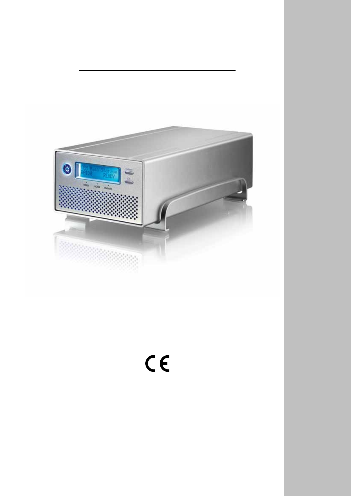
Taurus Super-S LCM
Dual-Bay RAID Storage Enclosure
for two 3.5” Serial ATA Hard Drives
User Manual
July 27, 2009 - v1.2
EN
Page 2

Taurus Super-S LCM Introduction
1 Introduction
1.1 System Requirements
1.1.1 PC Requirements
Minimum Intel Pentium III CPU 500MHz, 128MB RAM
eSATA equipped PC; Windows XP/Vista
FireWire 400/800 equipped PC; Windows XP/Vista
USB 2.0 equipped PC; Windows XP/Vista
Your hardware device must have the correct corresponding port (e.g. USB 2.0 host controller)
Plug & Play support for eSATA host controller
1.1.2 Mac Requirements
Minimum Apple G4 processor, 128MB RAM
eSATA equipped Mac; Mac OS 10.4 or above
FireWire 400/800 equipped Mac; Mac OS 10.2 or above
USB 2.0 equipped Mac; Mac OS 10.2 or above
Your hardware device must have the correct corresponding port (e.g. USB 2.0 host controller)
Plug & Play support for eSATA host controller
1.1.3 Supported Hard Drives
Two 3.5" SATA-I or SATA-II hard drives (1.5Gb/s or 3.0Gb/s)
20GB - 1.5TB per HDD
Hard drives of identical capacities are recommended
Supports large volumes in excess of 2TB
Note
In order for the computer to access volumes larger than 2TB, both the hardware and OS need to
have the capacity to support large volumes (e.g.: WinVista 32bit/64bit or Mac OS 10.4 and above).
1.2 Package Contents
Package content may vary depending on vendor & version.
Taurus Super-S LCM storage enclosure (hard drives not included)
Power supply
Interface cables
Manual
1.3 About this Manual
Firmware, images and descriptions can slightly vary between this manual and the actual product
you have. Functions and features may change depending on the firmware version. Please read
your warranty carefully, as this may vary between different vendors!
1.4 Trademarks
MS-DOS, Microsoft, Windows XP/Vista are trademarks of Microsoft Corporation.
Apple Macintosh and Mac are trademarks of Apple Computer.
All other third party brands and names are the property of their respective owners.
Page 1
Page 3
Taurus Super-S LCM Introduction
1.5 Detailed View
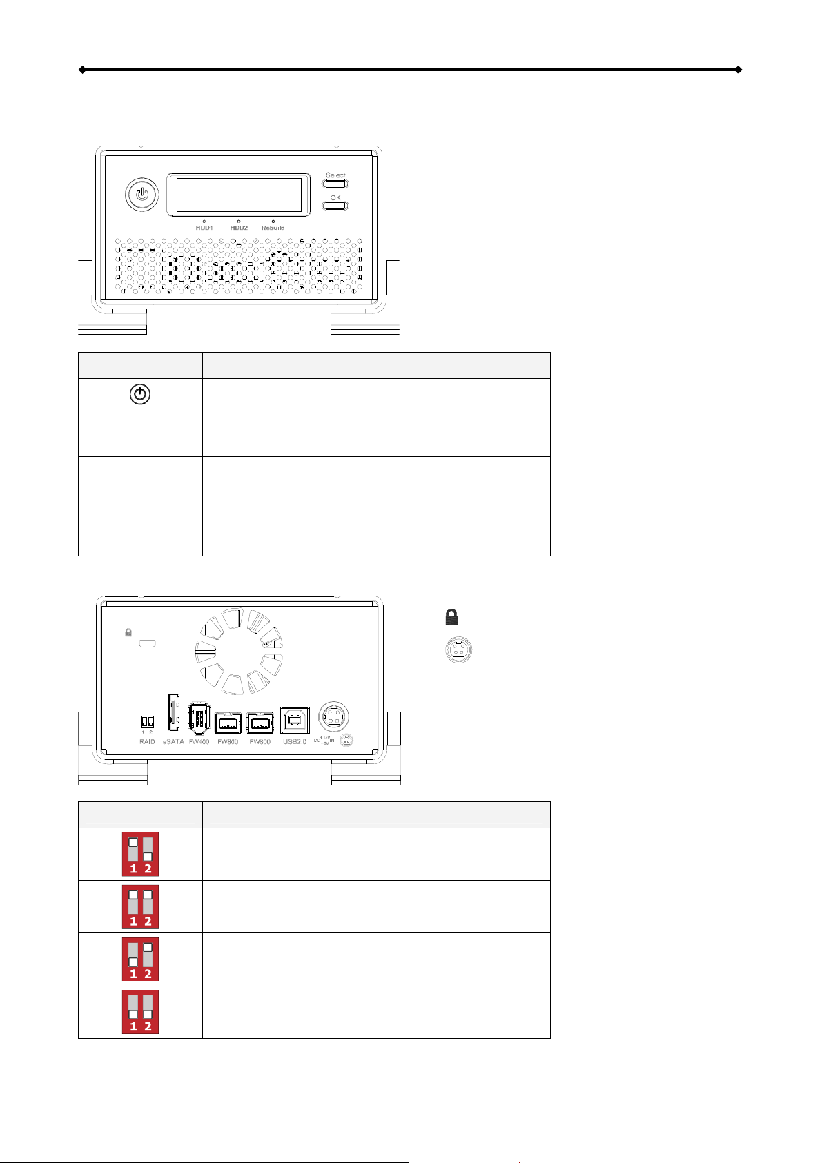
1.5.1 Front View
LED/Button Status
HDD1/2
Rebuild
Select
OK
1.5.2 Rear View
Power button; blue = power on
Green = Data access (read/write)
Red = Error or empty drive bay
OFF = HDD status normal
Yellow = Rebuilding data
Select setup menu or mode
Confirm current option or enter setup menu
To turn on t
power button for 1 second and then let go.
To turn it off, press and hold the power
button for 3 seconds and then let it go again.
Wait at least 5 seconds after turning off the
power, before turning it back on, or otherwise
it will not work.
he device, press and hold the
RAID Switch RAID Mode
RAID mode can be set via LCD display
Switch position: 1 up, 2 down
RAID mode is locked according to LCD setup
Switch position: 1 up, 2 up
RAID 1 (not possible to set RAID mode via LCD)
Switch position: 1 down, 2 up
RAID 0 (not possible to set RAID mode via LCD)
Switch position: 1 down, 2 down
= Security lock slot
= Power receptacle
eSATA = External SATA port
FW800 = FireWire 800 port
FW400 = FireWire 400 port
USB 2.0 = USB 2.0 High Speed port
Page 2
Page 4
Taurus Super-S LCM Introduction
1.6 RAID Modes
Hard drives of identical capacities are recommended. If the capacities are different, the total
amount of the space that can be used will depend on the drive with the smallest capacity. The
difference in performance is only visible for fast interfaces like eSATA.
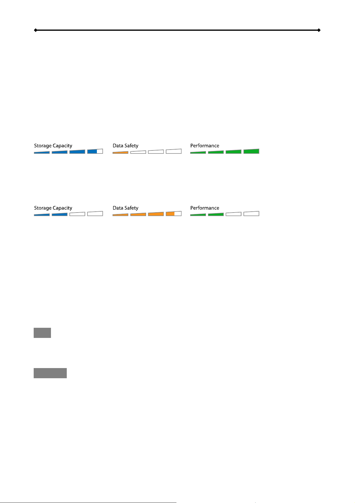
1.6.1 RAID 0 - Disk Striping
The drives are shown as one large single volume
smallest capacity. This setting is used where speed is the primary objective but RAID Level 0 (also
called striping) is not redundant. This form of array splits each piece of data across the drives in
segments; since data is written without any form of parity data-checking, it allows for the fastest
data transfer. On the downside, if one drive becomes damaged, the whole array can become
corrupted.
1.6.2 RAID 1 - Disk Mirroring
Two drives show up as
the smallest capacity, can be used. RAID 1 creates an exact copy (or mirror) of a set of data on the
second drive. This is useful when reliability and backup take precedence over storage capacity.
Should one hard drive fail, it can be replaced and the data rebuilt automatically.
one volume but only 50% of the total capacity, depending on the drive with
but the total size will depend on the drive with the
2 drives
2 drives
1.6.3 Changing the RAID Mode
The RAID mode should
1. Make sure the power is off and then install the hard drives.
2. Set the RAID switch and select your preferred RAID mode or choose the switch position to
later set the RAID mode via LCD display.
3. Turn on the power. If you have selected the option to set the RAID mode via LCD display,
enter the setup menu and set your preferred RAID mode now.
4. Initialize the disk, create a partition and format the drives.
5. Done.
Note
Changing the RAID mode requires you to re-format the drives. This will erase all data on the hard
drives that are being formatted. Make sure to backup all existing data first!
Important
In order for the computer to access volumes larger than 2TB, both the hardware and Operating
System need to have the capacity to support large volumes (e.g.: WinVista 32bit/64bit or Mac OS
10.4 and above).
be set after installing the drives and before first formatting the drives.
Page 3
Page 5
Taurus Super-S LCM System Setup
2 System Setup
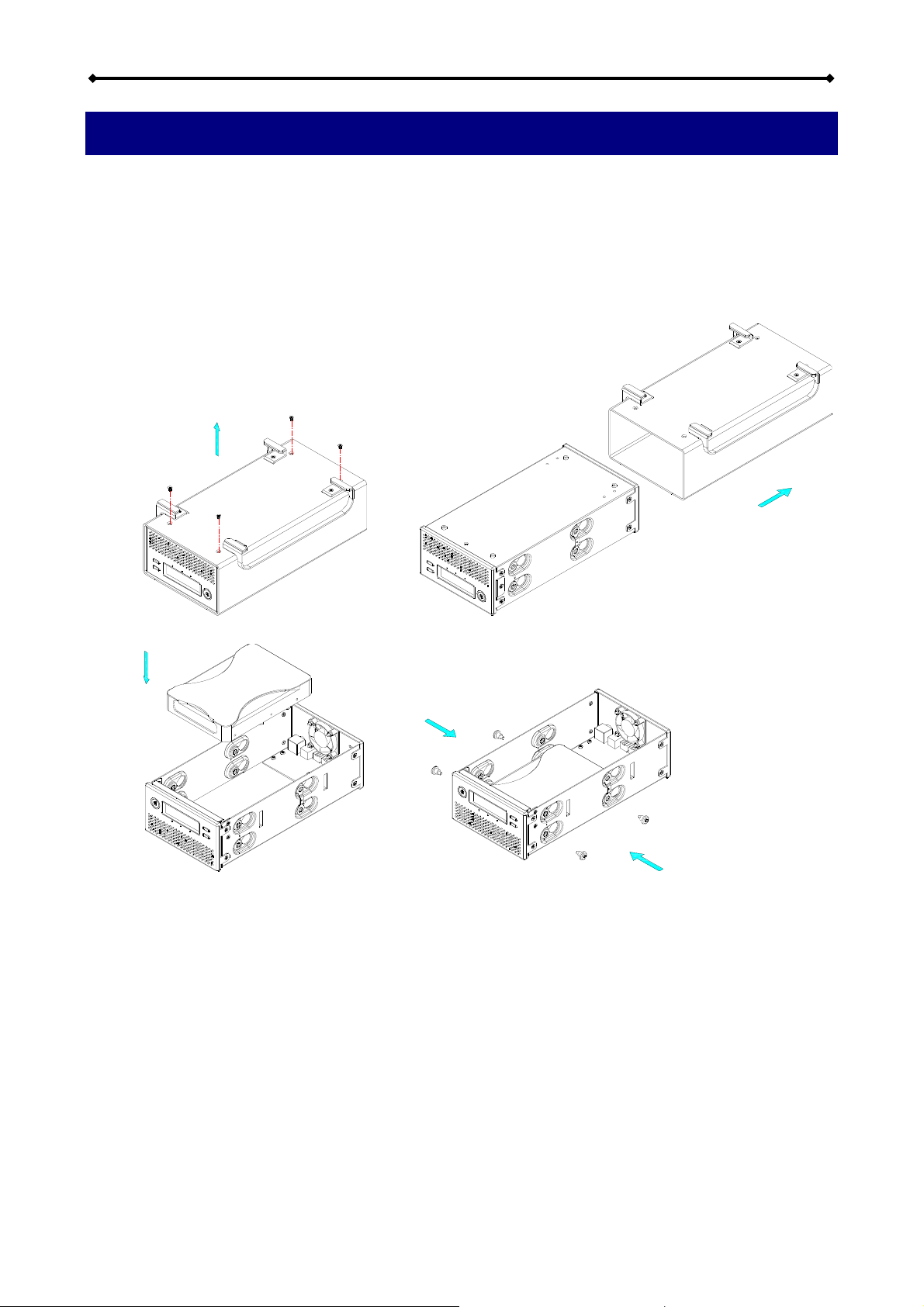
2.1 Hard Drive Assembly
Your unit may come with pre-installed hard drives. Before opening such an enclosure, please read
the warranty from your vendor carefully, as this could void your warranty.
1. Remove the four screws at the bottom of the case, push the inner chassis out and remove
the outer enclosure. The aluminium stand does not have to be removed for the assembly.
2. Install the first hard drive and mount it with two screws on each side.
3. Attach the thermal probe with the tape provided to the first HDD. Choose a place in
between the two drives but without damaging the probe when installing the second drive.
We also suggest not placing the thermal probe directly in front of the fan.
Page 4
Page 6

Taurus Super-S LCM System Setup
4. Install the second hard drive and mount it with two screws on each side.
5. Connect the SATA and power cables to your hard drives. Be careful not to damage any
components and confirm that the cables are connected firmly.
6. Slide the inner chassis back into the outer enclosure and fasten the four screws to finish the
assembly.
7. After turning on the power and connecting it to the computer use the disk management tool
(PC) or disk utility (Mac) to create a new partition and format the drives. If you have
selected the option to set the RAID mode via LCD display, set the RAID mode first, before
you format the drives.
8. Done! Your drive is now ready to use.
Note
This device is designed for two hard drives and does not work when only one HDD is installed.
Important
Upon initial start up of the device and when changing the RAID mode, any existing data on the
installed hard drives will be erased. Please make sure you backup all data prior to installing the
hard drives and prior to changing the RAID mode!
Page 5
Page 7

Taurus Super-S LCM System Setup
2.2 Replacing Hard Drives
When a drive fails, the corresponding HDD LED will light up red. If only one drive is defective and
the RAID mode is set to RAID 1, the data can still be accessed, however, we strongly recommend
replacing the faulty drive immediately to assure continued proper backup and data safety.
If more than one drive fails at the same time or if the RAID mode is set to RAID 0, the data will be
lost and the system can not be accessed again until the drive(s) have been replaced.
1. Check the HDD LED. The corresponding LED will light up red, indicating the defective drive.
2. Turn off the Taurus and remove the power supply from the wall socket.
3. Open the enclosure and replace the faulty hard drive with a new one.
4. Finish the assembly, connect the power supply and turn on the power.
5. For RAID 1, the RAID array will be rebuilt automatically. During this process, the Rebuild
LED will be flashing until all data is backed up. Rebuilding the RAID array will take several
hours, depending on the drive capacity.
6. For RAID 0, after turning on the power, go to the RAID setup menu, select RAID 0 and
confirm the settings. After the restart, simply format the drives.
Note
We recommend not turning off the power during the rebuild process but if the process is
interrupted, it will continue rebuilding the data as soon as the power is turned back on.
2.3 Connection to Computer
A few precautions and notes when using your external storage drive:
Do not expose the product to water or humid conditions.
Do not cover the enclosure’s ventilation holes.
Before connecting the device, install the hard drives and set your preferred RAID mode.
For the safe removal of your drive and to assure that no data is lost, always follow the correct
unplug procedure for external hardware (e.g.: Eject the drive before removal).
In order for the computer to access volumes larger than 2TB, both the hardware and Operating
System need to have the capacity to support large volumes (e.g.: WinVista 32bit/64bit or Mac
OS 10.4 and above) or the >2TB option should be disabled.
When the computer goes into stand-by mode, the hard drives in the external enclosure will spin
down as well.
Only one interface can be used at any given time.
2.4 About Data Backup
To protect your files and help prevent the loss of your data, we strongly recommend that you keep
two copies of your data, one copy on your Taurus and a second copy either on your internal drive
or another storage media such as CD, DVD, Tape or an additional external drive.
Any loss or corruption of data while using the Taurus is the sole responsibility of the user, and
under no circumstances will the manufacturer be held liable for compensation or the recovery of
this data.
Page 6
Page 8

Taurus Super-S LCM LCD Display
3 LCD Display
The LCD display shows the system status, detailed information about the hard drives as well as
the system configuration and provides the option to modify certain device settings.
To select a menu or change an option, use the [Select] button. To enter a menu and confirm a
change, use the [OK] button. For further details, follow the on-screen wizard or refer to the
following step by step descriptions.
3.1 Main Menu
Press the [Select] button to change between the different menus and press the [OK] button to
enter a menu.
1. The main screen displays the product name and the current RAID mode.
2. The system information will show further details about the device configuration and the
hardware.
3. The HDD information will show further details about the installed hard drives.
4. The settings menu offers options to change the device configuration.
3.2 System Information
Press the [Select] button until the system information menu is selected and then press the [OK]
button to start displaying further details about the device configuration and the hardware. It will
automatically cycle through the different information displaying each screen for about 8 seconds
and then return to the main screen. To fast forward, press the [Select] button.
1. The main screen of the system information menu.
2. The serial number is a combination of the 1394 vendor ID, the chip ID Hi and the chip ID Lo.
3. Displays the current firmware version of the Taurus Super-S LCM.
4. The I/O status shows the interface that is currently used for the connection to the computer.
5. Displays the current speed of the smart-fan and the temperature from its thermal probe.
6. Displays the current status of the >2TB and the alarm function.
7. Displays how the RAID mode is set (HW = DIP switch, LCM = LCD display, AP = external
program) and the total storage capacity.
Page 7
Page 9

Taurus Super-S LCM LCD Display
3.3 HDD Information
Press the [Select] button until the HDD information menu is selected and then press the [OK]
button to start displaying further details about the installed hard drives. It will automatically cycle
through the different information displaying each screen for about 8 seconds and then return to the
main screen. To fast forward, press the [Select] button.
1. The main screen of the HDD information menu.
2. Displays the model number and serial number of the drive installed at HDD1.
3. Displays the total storage capacity and the temperature of the drive installed at HDD1.
4. Displays the model number and serial number of the drive installed at HDD2.
5. Displays the total storage capacity and the temperature of the drive installed at HDD2.
Page 8
Page 10

Taurus Super-S LCM LCD Display
3.4 Settings
Press the [Select] button until the settings menu is selected and then press the [OK] button to enter
the configuration menu. You can now use the [Select] button to cycle through the different settings
and the [OK] button to further configure the device settings.
1. Option to enable or disable the support for large volumes in excess of 2TB.
2. Setup menu for the RAID settings.
3. Option to enable or disable the general alarm sound.
4. Option to enable or disable the temperature alarm sound.
5. Setup menu to define the fan speed of the smart fan.
6. Setup menu to define how long the backlight for the LCD display stays lit.
7. To exit the settings menu and return to the main menu.
3.4.1 >2TB Volume Mode
In order for the computer to access volumes larger than 2TB, both the ha
System need to have the capacity to support large volumes (e.g.: WinVista 32bit/64bit or Mac OS
10.4 and above) or the >2TB option should be disabled.
[Enabled] Supports volumes in excess of 2TB. If the total storage capacity exceeds 2TB, older
Operating Systems will not be able to mount and access the drive.
[Disabled] Only supports volumes up to 2TB. If the total storage capacity exceeds 2TB, the
remaining storage space can not be accessed but on the other hand, older Operating Systems
are still able to use the drive.
Press the [OK] button to enter the setup menu and press the [Select] button to cycle through the
different options.
To exit the menu without changing any of the settings, press the [Select] button until you see
the Exit screen and then press the [OK] button.
To change the setting, press the [Select] button to choose your preferred mode, press the [OK]
button to select it and then press the [OK] button again to confirm the change.
rdware and Operating
Page 9
Page 11

Taurus Super-S LCM LCD Display
3.4.2 RAID Mode Setup
In order to set the RAID
1 up, 2 down. To lock the setting once it has been changed via LCD display or to set it by using the
DIP switch, please refer to the “Rear View” paragraph.
[RAID 1] Confirm RAID 1 mirroring mode.
[RAID 0->1] Change the mode from RAID 0 striping to RAID 1 mirroring.
mode via LCD display, make sure the DIP switch position is set as follows:
[RAID 0] Confirm RAID 0 striping mode.
[RAID 1->0] Change the mode from RAID 1 mirroring to RAID 0 striping.
Press the [OK] button to enter the setup menu and press the [Select] button to cycle through the
different options.
To exit the menu without changing any of the settings, press the [Select] button until you see
the Exit screen and then press the [OK] button.
To change the setting, press the [Select] button to choose your preferred mode, press the [OK]
button to select it, press the [OK] button again to confirm the change and once more to
acknowledge that all data will be erased by this change. The device will restart automatically
and after start up, one more confirmation is required to set the new RAID mode.
Note
Changing the RAID mode requires you to re-format the drives. Make sure to backup all existing
data first!
Page 10
Page 12

Taurus Super-S LCM LCD Display
3.4.3 Alarm Setup
The general alarm sound is the short beep you hear when starting up the system and it will sound
when something is wrong. To enable or disable the alarm, do one of the following.
[ON] Beeper and alarm is enabled.
[OFF] Beeper and alarm is disabled.
Press the [OK] button to enter the setup menu and press the [Select] button to cycle through the
different options.
To exit the menu without changing any of the settings, press the [Select] button until you see
the Exit screen and then press the [OK] button.
To change the setting, press the [Select] button to choose your preferred mode and then press
the [OK] button to confirm the change.
3.4.4 TEMP Alarm Setup
This is t
reaches a critical level (>60˚C). You can enable or disable it here.
[ON] High temperature alarm is enabled.
[OFF] High temperature alarm is disabled.
Press the [OK] button to enter the setup menu and press the [Select] button to cycle through the
different options.
To exit the menu without changing any of the settings, press the [Select] button until you see
To change the setting, press the [Select] button to choose your preferred mode and then press
he alarm sound you hear when the temperature that is measured by the thermal probe
the Exit screen and then press the [OK] button.
the [OK] button to confirm the change.
Page 11
Page 13

Taurus Super-S LCM LCD Display
3.4.5 Fan Speed Setup
For the smart-fan to automatically regulate the fan speed according to the internal temperature, the
thermal probe has to be installed.
[Automatic] Regulates the fan speed according to the internal temperature (below 40˚C = low
speed, 40-50˚C = medium speed, above 50˚C = high speed).
[HighSpeed] Fan speed is set to high speed.
[LowSpeed] Fan speed is set to low speed.
[OFF] The fan is turned off. This setting should only be used if the device is located in a cool
and temperature controlled room.
Press the [OK] button to enter the setup menu and press the [Select] button to cycle through the
different options.
To exit the menu without changing any of the settings, press the [Select] button until you see
the Exit screen and then press the [OK] button.
To change the setting, press the [Select] button to choose your preferred mode and then press
the [OK] button to confirm the change.
Page 12
Page 14

Taurus Super-S LCM LCD Display
3.4.6 Backlight Setup
The backlight for the LCD display can be enabled, disabled or set so that it turns off automatically,
when the screen has been idle for a certain amount of time.
[ON] Always ON.
[OFF] Always OFF.
[1min] Backlight turns off when the screen has been idle for more than one minute.
[3min] Backlight turns off when the screen has been idle for more than three minutes.
[5min] Backlight turns off when the screen has been idle for more than five minutes.
Press the [OK] button to enter the setup menu and press the [Select] button to cycle through the
different options.
To exit the menu without changing any of the settings, press the [Select] button until you see
the Exit screen and then press the [OK] button.
To change the setting, press the [Select] button to choose your preferred mode and then press
the [OK] button to confirm the change.
Page 13
Page 15

Taurus Super-S LCM LCD Display
3.5 Event Information
In addition to the details about the hardware and device configuration, the LCD display will also
show certain event information. Following is a list of possible messages and their meanings.
[HDD Error / Remaining 1xHDD]
When using RAID 0 and one of the drives fails, the alarm will go off and the display indicates
that only one good drive remains. Refer to the HDD LED’s in order to locate the defective drive.
[RAID Warning / Degraded Array]
When using RAID 1 and one of the drives fails, the alarm will go off and the display shows this
message. Press the [OK] button to temporarily mute the alarm and use the HDD LED’s in order
to locate the defective drive.
[XX Cable / Connected]
Shows which cable has been connected.
[Cable / Disconnected]
Shows when the cable has been unplugged.
[Rebuilding… / Hrs left xhxxmin]
Shows during the rebuild process of a RAID 1 array with an approximate time in hours and
minutes indicating how long it takes until the backup is done.
[Alarm / High Temperature]
Indicates critical temperature (>60˚C).
[Alarm / Fan Failure]
Indicates a fan failure or unexpectedly slow RPM.
[Detecting Disk / Starting…]
Shows during start up of the system.
[XX / Starting …]
Shows during start up of the system.
[Check DIP Switch]
Shows when trying to change the RAID mode via LCD display but the DIP switch is set to a
specific RAID mode already.
[Modify DIP Switch]
Shows when pressing Abort after changing the DIP switch to a different RAID mode.
Remember to modify the DIP switch and set it back to the previous mode if you don’t want to
change it.
[RAID Mode Locked]
Shows when trying to change the RAID mode via LCD display but the DIP switch is set to lock
the settings.
Page 14
Page 16

Taurus Super-S LCM Appendix
4 Appendix
4.1 Precautions
4.1.1 Power on/off precautions
It is highly recommended to switch the unit off when not in use. When re-locating the device or
when not in use for an extended period of time, we strongly recommend unplugging the unit.
4.1.2 Location and placing precautions
Avoid positioning your device in the
Locations with direct sunlight, next to radiators, other sources of heat.
Locations with very high temperatures (more than 38°C) or humidity (more than 90%).
Very dusty or sandy locations.
Locations subject to vibration, shock, or with a sloping base.
4.1.3 Electricity and power plug
Careful atte
ntion must be paid to the following points in order to prevent damage, fire, and/or injury:
When removing the power cable from the socket, pull on the plug fixture and never on the cord.
Do not connect and remove the power cable with wet hands.
Keep the power cable away from heaters.
Never try to repair the power cable yourself or to modify it in any way.
If the unit is dropped or becomes damaged in any other way, unplug the power cable.
Always connect the power adapter to your device before you plug it into the wall socket.
4.1.4 Cables
Use only the cables
supplied or recommended by your vendor in order to avoid the risk of
malfunction, electric shock, and/or possible interference to the device.
4.2 FAQ
following places:
Q: What file system should I choose to format my drive?
A: This will depend on how you want to use the drive but in general, we recommend:
Windows XP/Vista NTFS
Mac OS X HFS+ (Mac OS Extended)
To use it on both PC and Mac FAT32 (single file size is limited to 4GB)
Q: How many drives can fail before I loose my data?
A: For RAID 0, any drive failure will result in the data being lost. For RAID 1, more than one drive
failure at the same time will mean the data can not be recovered anymore.
Q: Can I install only one hard drive?
A: No, the Taurus Super-S LCM requires two hard drives.
© Copyright 2009 by Macpower & Tytech Technology Co., Ltd. all Rights Reserved
The information contained in this manual is believed to be accurate and reliable. Macpower & Tytech Technology
assumes no responsibility for any errors contained in this manual. Macpower & Tytech Technolog y reserves the right to
make changes in the specifications and/or design of this product without prior notice. The diagrams contained in this
manual may also not fully represent the product that you are using and are there for illustration purposes only. Macpower
& Tytech Technology assumes no responsibility for any diff erences between the product mentioned in this manual and
the product you may have.
Page 15
 Loading...