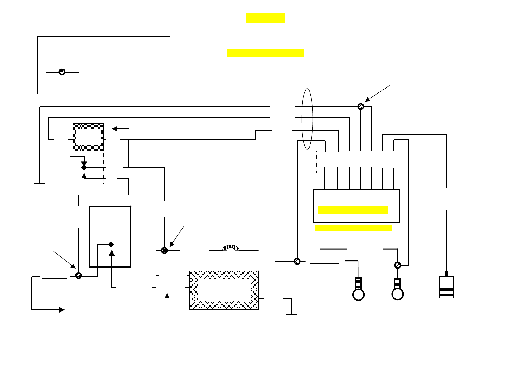
|
|
|
|
|
|
|
|
|
|
|
|
|
|
|
|
|
|
TATA 407 |
|
|
|
|
|
|
|
|
|
|
|
|
|
|
|
|
|
|
|
Little Black Box Engine Monitor |
|
||||
|
|
|
|
|
|
|
|
|
|
|
|
|
|
|
|
|
|||||
|
|
|
|
|
|
|
|
|
|
|
Legend |
|
|
Wiring Diagram |
|
||||||
|
|
|
|
|
|
|
|
|
|
|
|
|
|
|
|
( |
EMS IV & Turbo Timer |
) |
|
||
|
|
|
|
|
|
|
|
|
|
|
|
|
|
|
|
|
|||||
|
Red / Green |
|
|
|
|
|
Bold indicates existing wiring |
|
|
|
|||||||||||
|
|
|
|
|
|
|
|
|
|
|
|
|
|||||||||
|
|
|
|
|
|
|
|
|
|
|
|
|
|
|
|
|
|
|
|
|
|
|
|
|
|
|
|
|
|
|
|
|
Indicates Tap connector |
|
|
|
|
|
|
LBB Harness |
|
||
|
|
|
|
|
|
|
|
|
|
|
|
|
|
|
|
|
|
||||
|
|
|
|
|
|
|
|
|
|
||||||||||||
|
|
|
|
|
|
|
|
|
|
|
|
|
|
|
|
|
|
|
|
||
|
|
F-M |
|
|
|
|
|
|
Indicates Male / Female connectors |
|
|
|
|
NB: Earth Brown Wir:e |
|||||||
|
|
|
|
|
|
|
|
|
|
|
|
|
|
|
|
|
|
|
|
|
|
|
|
|
|
|
|
|
|
|
|
|
|
|
|
|
|
|
|
|
|
|
|
|
|
|
|
Black |
|
|
|
|
|
|
|
|
|
|
|
White |
|
|
|
|
|
|
|
|
|
|
Relay located on the |
Red |
|
|
|
|
|
|
|
|
LBB |
|
Wiper Motor bracket |
|
|
|
|
|
|
|
|
86 |
85 |
|
|
|
|
|
|
|
|
||
Relay |
|
|
|
|
|
|
|
|
|
||
87a |
|
30 |
|
<![if ! IE]> <![endif]>Green |
<![if ! IE]> <![endif]>Red |
<![if ! IE]> <![endif]>White |
<![if ! IE]> <![endif]>Black |
<![if ! IE]> <![endif]>Brown |
<![if ! IE]> <![endif]>Yellow |
<![if ! IE]> <![endif]>Orange |
Connector |
|
|
|
|
|
|
|
|
|
|
|
LBB |
|
|
87 |
|
|
|
|
|
|
|
|
|
Earth on Wiper |
|
|
|
|
|
|
|
|
|
|
|
|
|
|
|
|
|
|
|
|
|
|
|
|
|
|
|
|
|
|
|
|
|
|
|
|
|
|
|
|
|
|
<![if ! IE]> <![endif]>Purple |
|
|
|
|
|
|
<![if ! IE]> <![endif]>Red |
|
|
|
|
|
|
|
|
|
|
|
|
|
<![if ! IE]> <![endif]>Yellow |
|||||||||||||||||||
Motor mount |
|
|
|
|
|
|
|
|
|
|
|
|
|
EMS IV |
|
||||||||||||||||||||||||||
|
|
|
|
|
|
|
|
|
|
|
|
|
|
|
|
|
|
|
|
|
|
|
|
|
|
|
|
|
|
|
|
|
|
||||||||
Bracket. |
|
|
|
|
|
|
|
|
|
|
|
|
|
|
|
|
|
|
|
|
|
|
|
|
|
|
|
|
|
|
|
|
|
|
|||||||
|
|
|
|
|
|
|
|
|
|
|
|
|
|
|
|
|
|
|
|
|
|
|
|
|
|
|
|
|
|
|
|
|
|
|
|
|
|
|
|
||
|
|
|
|
|
|
|
|
|
|
|
|
|
|
|
|
|
|
|
|
|
|
|
|
|
|
|
|
|
|
|
|
|
|
|
|
|
|
|
|||
|
|
|
|
|
|
|
Timer |
|
|
|
|
|
|
|
|
|
|
|
|
|
|
|
|
|
|
|
|
|
|
|
|
NB: Cut Fail Safe Jumper |
|
|
|
|
|
||||
|
|
|
|
|
|
|
|
|
|
|
|
|
|
|
|
Tap onto existing wire before |
|
|
|
|
|
|
|
|
|
|
|
|
|
|
|
|
|||||||||
|
|
|
|
|
|
|
Delay |
|
|
|
|
|
|
|
|
|
connection to Turbo Timer |
|
|
|
|
|
|
|
|
|
|
|
|
|
|
|
|
||||||||
|
|
|
|
|
|
|
|
|
|
|
|
|
|
|
|
|
|
|
|
|
|
|
|
|
|
|
|
|
|
|
|
|
|||||||||
|
` |
|
|
|
|
|
Relay |
|
|
|
|
|
|
|
|
|
|
|
|
|
|
|
|
|
|
|
|
|
|
|
|
|
|
|
|
|
|
|
|
|
|
|
|
|
|
|
|
|
|
|
|
|
|
|
|
|
|
|
|
|
|
|
|
|
|
|
|
|
Adjust EMS alarm to 100 – 105 deg C. |
|
|
|
|
|
|||||||||
|
|
|
|
|
|
|
|
|
|
|
|
|
|
|
|
|
|
|
|
|
|
|
|
|
|
|
|
|
|
|
|
|
|
||||||||
|
|
|
|
|
|
(Engine stop) |
|
|
|
|
|
|
|
|
|
|
|
|
Engine Gauges |
|
|
|
|
|
|
|
|
|
|
|
|||||||||||
|
|
|
|
|
|
|
|
|
|
|
|
|
|
|
|
|
|
|
|
|
|
|
|
|
|
|
|
||||||||||||||
Tap onto |
|
|
|
|
|
|
|
|
|
|
|
|
|
|
|
|
|
|
|
|
|
|
|
|
|
|
|
|
|
|
|
||||||||||
|
|
|
|
|
|
|
|
|
|
|
|
|
|
|
|
|
|
|
|
|
|
|
|
|
|
|
|
|
|
|
|
|
|
|
|
||||||
|
|
|
|
|
|
|
|
|
|
|
|
|
|
|
|
|
|
|
|
|
|
Fuse |
|
|
|
|
|
|
|
|
|
|
|
|
|
|
|
|
|||
|
existing wire |
|
|
|
|
|
|
|
|
|
|
|
|
|
|
|
|
|
|
|
|
|
|
|
|
|
|
|
|
|
|
|
|
|
|
|
|
|
|||
|
|
|
|
|
|
|
|
|
|
|
|
|
|
|
|
|
|
|
|
|
|
|
|
|
|
|
|
|
|
|
|
|
Blue / Black |
|
|
|
|
|
|
|
|
|
|
|
|
|
|
|
|
|
|
|
|
|
|
|
|
|
|
|
Orange/Green |
|
|
|
|
|
|
|
|
|
|
|
|
|
|
|
|
|
|
|
|
||
|
|
|
|
|
|
|
|
|
|
|
|
|
|
|
|
|
|
|
|
|
|
|
|
|
|
|
|
|
|
|
|
|
|
|
|
|
|||||
|
|
|
|
|
|
|
|
|
|
|
|
|
|
|
|
|
|||||||||||||||||||||||||
|
|
|
|
|
|
|
|
|
|
|
|
|
|
|
|
|
|
|
|
|
|
|
|
|
|
|
|
|
|
|
|
|
|
|
|
|
|
|
|
||
|
|
|
|
|
|
|
|
|
|
|
|
|
|
|
|
|
|
|
|
|
|
|
|
|
|
|
|
|
|
|
|
|
|
|
|
|
|
|
|
||
|
|
|
|
|
|
|
|
|
|
|
|
|
|
|
|
|
|
|
|
|
|
|
|
|
|
|
|
|
|
|
|
|
|
|
|
|
|
|
|
|
|
|
|
|
|
|
|
|
|
|
|
|
|
|
|
|
|
|
|
|
|
|
|
|
|
|
|
|
|
|
|
Green / Black |
|
|
|
|
|||||||
|
|
|
|
|
|
|
|
|
|
|
|
|
|
|
|
|
|
|
|
|
|
|
|
|
|
|
|
|
|
|
|
|
|
||||||||
|
|
|
|
|
|
|
|
|
|
|
|
|
|
|
|
|
|
|
|
|
|
|
|
|
|
|
|
|
|
|
|
||||||||||
|
|
|
|
|
|
|
|
|
|
|
|
|
|
|
|
|
|
|
|
|
|
|
|
|
|
|
|
|
|
|
|
|
|||||||||
|
|
|
|
|
|
|
|
|
|
|
|
|
|
|
|
|
|
|
|
|
|
|
|
|
|
|
|
|
|
|
|
|
|
|
|
|
|
|
|
|
|
|
|
|
|
|
|
|
|
|
|
|
|
|
|
|
|
|
|
|
|
|
|
|
|
|
|
|
|
|
|
|
|
|
|
|
|
|
|
|
|
|
|
|
|
|
|
|
|
|
|
|
|
|
|
|
|
|
|
|
|
|
|
|
|
|
|
|
|
|
|
|
|
|
|
|
|
|
|
|
|
|
|
|
|
Blue/Yellow |
F-M Blue |
|
Red |
+12v Battery |
|
Orange/Green |
M-F White |
Turbo Timer |
|||
|
|
||||
|
|
(Optional) |
Black |
|
|
|
|
|
|
|
|
|
|
|
|
Ignition |
Oil |
Cylinder Head |
To engine stop vacuum solenoid |
|
|
|
|
|
|||
|
||||||||
|
|
|
|
|
|
Light |
Pressure |
Temperature |
|
|
|
|
|
|
|||
|
Note: - Use Male / Female connectors as |
|
|
|
(Alternator) |
Light |
Sensor |
|
|
||||||||
|
shown so the original circuit can be |
|
|
|
|
|
|
|
|
|
|
|
|
|
|
||
|
restored if required. |
|
|
|
|
|
|