

Page 1
Page 2

Page 3

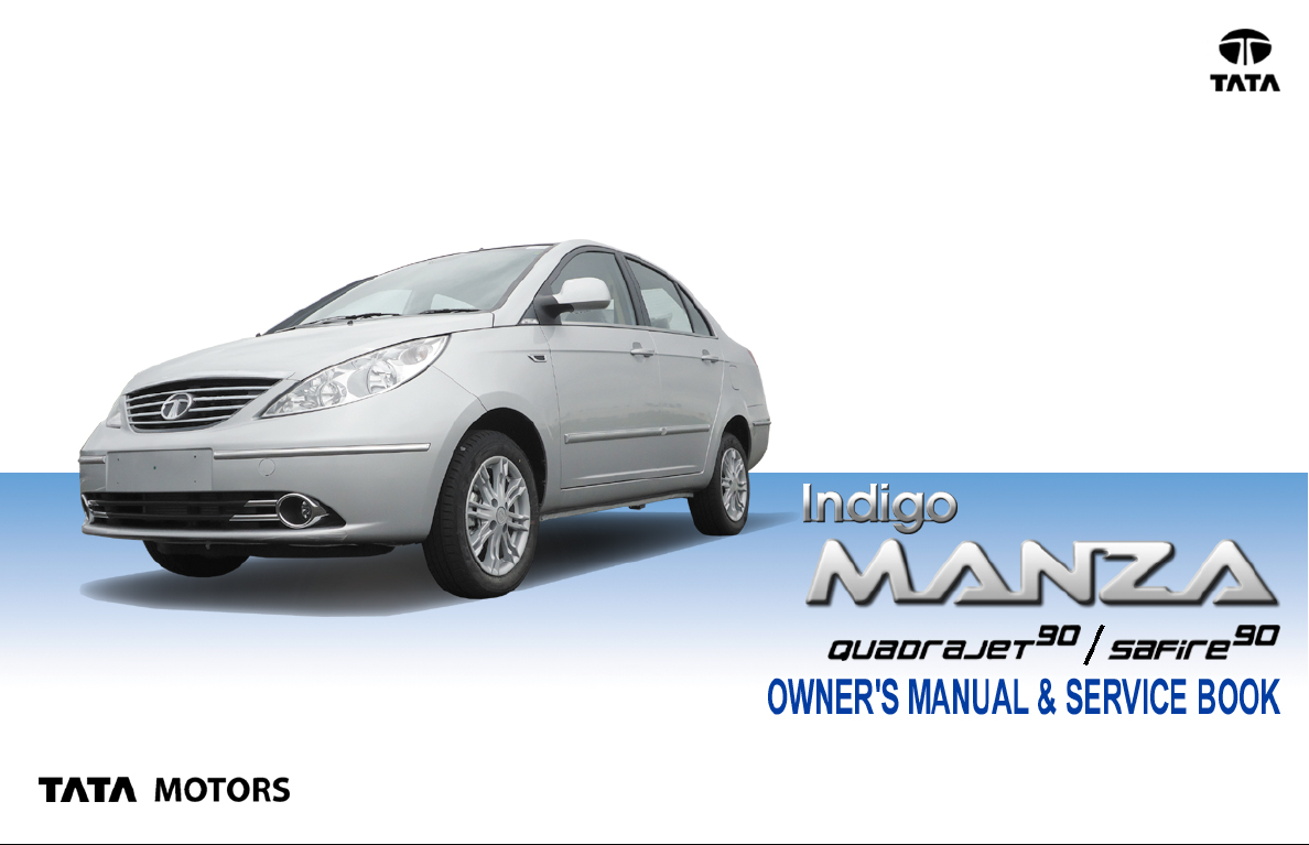
Owner's Manual & Service Book
The contents given in this book are not binding & are subject to change without notice & images shown are
for illustration purpose only .
Paasenger Car Business Unit (PCBU)
Mumbai, Pune
1
Page 4

Q
Please read this Owner’s Manual carefully before you start using your car and keep it safely in the car’s glove box at
all times.
Q
The recommended routine maintenance servicing along with any running repairs that may be required, should be
entrusted to T AT A Authorised Workshop to ensure that only latest methods and genuine TA T A MOTORS replacement
parts are used for the continued reliability , safety and performance of the vehicle.
Q
Some of the items / accessories / features shown / given in this book may not be fitted on your vehicle, but they are
applicable for other versions of T at a Indigo Manza.
Q
(C) Copyright 2012 T ATA MOTORS
Q
All rights reserved. The material in this manual shall not be reproduced or copied, in whole or in part, in any form
without written permission from T A T A MOT ORS.
Q
The information and specifications given in this book are valid as on the date of printing. TATA MOTORS Limited
reserves the right to make changes in design and specifications and/or to make additions to or improvements in this
product without obligation to install them on products previously sold.
Q
In the event of the Vehicle being sold, please ensure that this manual is lef t in the vehicle for the reference of the new
owner.
2
Page 5

Dear Customer,
Thank you for choosing T at a Indigo Manza.
Built on the new car platform from Tata Motors, your T ata Indigo Manza is the perfect blend of form
and functionality .
This owner’s manual provides you with all the information you need to fully understand your
T at a Indigo Manza and make your ownership of T a t a Indigo Manza a delightful experience. We
would recommend that you go through the owner’s manual in order to get the most out of your
car.
Regular servicing of your car ensures its road worthiness & trouble-free operation, hence we
request you to get your vehicle checked as per service schedule at any of our authorised service
outlets.
We are privileged to have you as our valued customer .
Drive the T ata Indigo Manza. Discover how it changes everything.
We wish you Happy Motoring
3
Page 6

CUSTOMER ASSISTANCE
Safety and vehicle damage warnings
In this manual, you will see WARNING, CAUTION and
NOTICE warnings.
WARNING
Indicates a strong possibility of severe personal injury or
death if the instructions are not followed.
CAUTION
This is an indicator which may cause injury to people if it
is ignored. You are informed what you must or must not
do in order to avoid or reduce the risk to yourself and
other people.
NOTICE
This is an indicator which may cause damage to the car
or its equipment if it is ignored. You are informed what
you must or must not do in order to avoid or reduce the
risk of damage to your car and its equipment.
Safety symbol
In this manual, you will also see a circle
with a slash. This means "Do not", "Do not
do this", or "Do not let this happen".
Important Information about this manual
4
Page 7

CONTENTS
KNOW YOUR INDIGO MANZA 07
24x7 ON ROAD ASSISTANCE 09
V ALUE ADDED SERVICE 13
ENVIRONMENTAL CARE 23
WARRANTY - TERMS & CONDITIONS 25
INDIGO MANZA A T A GLANCE 27
GETTING STARTED 87
DRIVING 103
IN CASE OF EMERGENCY 113
PRELIMINARY TROUBLE SHOOTING 121
ELECTRICAL MAINTENANCE 131
CAR CARE 139
MAINTENANCE 145
IMPORTANT TECHNICAL INFORMATION 161
VEHICLE SERVICE 173
5
Page 8

6
Page 9
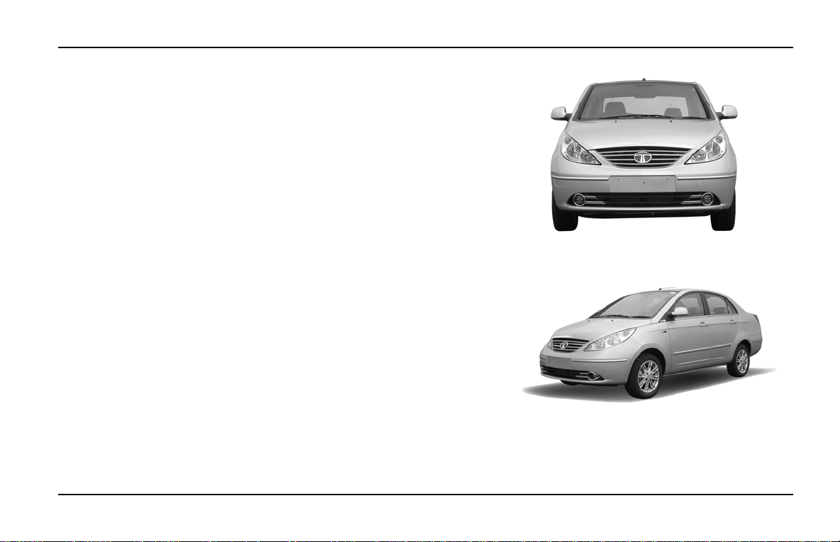
KNOW YOUR T AT A INDIGO MANZA
Your Tata Indigo Manza is the perfect blend of form and functionality.
Built on the new car platform from TA T A MOT ORS, the T ata Indigo Manza
is bigger in size and interior space, but its contemporary styling and sharp
lines give it a compact sporty look. The new petal-shaped headlamps add
a dash of panache to the front and the all enveloping tail lamps are unique
in its class.
The contemporary styling continues in the refreshed interiors, with the
stylish Two-tone Dashboard, Bright crome pack, Leather seats, Touch
Screen Music & Navigation System (For few variants) and FATC-Fully
Automatic T emperature Control (For few variants). The adjustable driver’s
seat and the tilt adjust steering wheel enable better driving posture while
the best in class interior space results in unmatched comfort. The all new
floor console comes with well-designed utility spaces.
The T at a Indigo Manza is also a leap in terms of technology . It is powered
by new generation engines; the globally acclaimed advanced
QUADRAJET Diesel Engine and SAFIRE Petrol Engine with new
synchromesh power train that will change the way you drive. Its improved
rear suspension and its bigger and wider tubeless tyres with new style
alloy wheels increase ride comfort.
7
Page 10

8
Page 11
Dear Customer,
It is our responsibility and our endeavour to ensure that you
have our complete service backup if ever, wherever and
whenever you need the same. When you have a road
network that spans wide area, the probability of a breakdown
happening within hailing distance of a TATA MOTORS
Authorized Workshop is very low. It is Precisely for this
reason, we have tied up with MyTVS, who will provide
breakdown assistance including towing to the nearest TA TA
MOTORS Authorized Workshop through their Authorized
Service Providers (ASP)
24X7 ON ROAD ASSISTANCE
The 24X7 On Road Assistance Program shall be
automatically available to your vehicle for the duration of
Warranty period. The program shall also be available, if
you avail the same post warranty .
Response Time ** for the On Road Assistance Program
Within City Limits 60 minutes
On St ate or National Highways 90 minutes
Ghat Roads and other places 120 minutes +/-
**(The response time will depend on the location, terrain,
traffic density and the time of the day .)
Standard procedure when calling for On Road
Assistance in case of a breakdown:
• Dial the toll free help line number – 1 800 209 7979
• Identify your vehicle with the Vehicle chassis number
that is available in the Owners Service manual.
• Explain your exact location with landmarks and tell us
about the problem you face with the vehicle.
• Park your vehicle on the edge of the road, open the
bonnet and put on the hazard warning signal.
• Place the advance warning triangle supplied with the
vehicle approx. 3 m from the vehicle in the direction of
on coming traffic.
.
9
Page 12

24X7 ON ROAD ASSISTANCE
COVERAGE UNDER THE 24 X 7 ON ROAD ASSIST ANCE
PROGRAM
I. The 24x7 On Road Assistance Program Service
covers the following services on your vehicle during
warranty period.
• Wheel change through spare wheel.
• Arrangement of fuel. (Fuel cost will be chargeable at
actual cost)
• Re-opening the vehicle in cases of key lock out.
• Rectification of electrical problems related to battery ,
fuses etc.
• On spot repairs for complaints repairable at site.^
• Vehicle to vehicle towing or winching & towing for non
accident cases up to the nearest TATA MOTORS
authorized workshop. Towing charges at actual cost
beyond the same to be paid to the ASP in cash. (Any
ferry or toll charges levied in relation to the vehicle being
towed to be paid by the customers in actuals in cash).
For accident cases, towing charges to be borne by the
costomer.
II. The 24x7 On Road Assistance Program coverage on
availing the 24X7 policy, post warranty is upto maximum
10
of 6 instance of assistance in one year for both the
plans- Basic and Premium. In the premium plan, this
includes 1 instance of towing upto the nearest TATA
MOTORS authorised workshop.
EXCLUSIONS
24x7 On Road Assistance Program does not apply to
• Cost of parts consumables and labour for such repairs
not covered under warranty*. These charges are to be
settled with ASP in cash.
• Toll or ferry charges paid by ASP in reaching to the
breakdown site to be settled with ASP in actuals in
cash.
• Cases involving accident, fire, theft, vandalism, riots,
lightening, earthquake, windstorm, hail, tsunami,
unusual weather conditions, other acts of God, flood,
etc.
• Vehicles that are unattended, un-registered,
impounded or abandoned.
• Breakdown/defects caused by misuse, abuse,
negligence, alterations or modifications made to the
vehicle.
• Lack of maintenance as per the maintenance
schedule as detailed in the owner’s manual.
Page 13

24X7 ON ROAD ASSISTANCE
• Cases involving racing, rallies, vehicle testing or
practice for such events..
Disclaimer
• The service is not available in the some part of J&K
and in Union T erritories of Andaman & Nicobar Islands
and Lakshwadeep.
• **The reach time is indicative & the actual reach time
will be conveyed by the call centre at the time of
breakdown call.
• The reach time can vary depending on the traffic density
& time of the day .
• The reach time indicated does not account for delays
due to but not limited to acts of God, laws, rules &
regulations for time being in force, orders of statutory
or Govt. authorities, industrial disputes, inclement
weather, heavy down pour, floods, storms, natural
calamities, road blocks due to accidents, general strife
and law & order conditions viz. fire, arson, riots, strikes,
terrorist attacks, war etc.
• ^ On spot repairs at breakdown site shall depend on
nature of complaints & will be as per the discretion of
the ASP .
• *The decision for free of charge repairs will be as per
the warranty policy & procedures of TATA MOTORS
LTD. and as per the interpretation of the same by ASP.
Y ou will be duly informed by the ASP & call centre for
the change applicable if any .
• All charges wherever applicable need to be settled
directly with the ASP.
11
Page 14

24X7 ON ROAD ASSISTANCE
EXCLUSION OF LIABILITIES :
• It is understood that TA T A MOTORS shall be under no
liability whatsoever in respect of any loss or
damage arising directly or indirectly out of any delay in
or non delivery of, defect/deficiency in service/parts
provided by ASP.
• In case vehicle cannot be repaired on-site, customers
are advised to use the towing facility for taking their
vehicle to the nearest TATA MOTORS authorized
workshop only . In no condition will the vehicle be towed
to any unauthorized workshop. TATA MOTORS will
not be responsible for any repairs carried out in such
unauthorized workshop.
• Customer are advised to take acknowledgment from
the ASP for the list of accessories/extra fittings and
other belongings in the vehicle as well as the current
condition related to dents/scratches breakages of parts/
fitments of the vehicle at the time of ASP taking
possession of the vehicle & to verify these items when
delivery is taken back by them, Claim for loss of or
damage to items, if any should be taken up with ASP
directly. TATA MOTORS shall not be responsible for
any such claims, damages/loss or any deficiency of
service of the ASP.
• Vehicles will be handled, rep aired & towed as per the
customer’s risk & TATA MOTORS shall not be liable
for any damages / claims as a result of the same.
• Services entitled to the customers can be refused or
cancelled on account of abusive behaviour, fraudulent
representation, malicious intent and refusal to pay the
charges for any charges related services and spare
parts during service or on previous occasion on part of
the customer.
• On site repairs may be temporary in nature. The
completion of repairs does not certify the road
worthiness of the vehicle. The customer is advised to
ensure temporary repairs carried out onsite is followed
by permanent repairs at TATA MOTORS Authorized
Workshop at the earliest.
• Terms and conditions and service coverage,
exclusions etc. are subject to change without notice.
12
Page 15

V ALUE ADDED SERVICE
Dear Customer,
It is our never ending responsibility and endeavor to ensure that our customer’s expectations are fulfilled comprehensively . T o fulfill your vehicle service needs, we recommend the following :
1) Extended Warranty
2) Anti Rust / Sound Deadening / Engine waxing treatment
3) Car detailing programming : Exterior Enrichment and Interior Enrichment Program
These products shall help maintain optimum vehicle performance and shall enhance vehicle life.
We have tied up with best in the Class companies, who would bring you the above world class products at affordable
prices. The above products are available with all our Dealers, T ASCs and T ASPs.
Our Dealer Service marketing executive shall explain to you the benefits of the above mentioned products.
13
Page 16

V ALUE ADDED SERVICE
TATA MOTORS recommends the purchase of Extended its warranty program.
Coverage : Mechanical + Electrical + Emission
Benifits :
• Insures you against unforeseen break down repair bills.
• Documentation is simple and hassle free.
• Near cashless & speedy claim settlement.
Term :
• 24 + 12 or 150000 kms whichever occurs first
• 24 + 24 or 150000 kms whichever occurs first
Extended Warranty available in the dealership from where you have
purchased your vehicle. We strongly recommend purchase of Extended
Warranty at time of purchase of your vehicle. Surcharge applicable on
purchase of Extended Warranty after 90 days of purchase of vehicle. Extended
Warranty can be availed till 421 days from date of purchase of vehicle.
The Dealer Service Marketing Executive shall explain to you the Terms and
conditions, Coverage and Owner’s responsibility.
Extended Warranty Booklet & Cover Note :
The Extended Warranty booklet and cover note is the basis of the contract between TA TA MOTORS LIMITED and the Owner of the
vehicle shown on the Extended Warranty booklet. The Customer to retain this booklet and the same to be produced to the dealer
while claiming benefits under Extended Warranty.
14
Page 17

V ALUE ADDED SERVICE
Note :
• The 12 / 24 month extended warranty does not follow the 24 month Manufacturer's warranty.
• The extended warranty comes into force once the manufacturer’s warranty expires e.g. after 24 Months.
• It is more restrictive as by the time it comes into force the vehicle is already 24 months old.
What is covered ?
• Mechanical / Emission / Electrical break down as defined in this warranty and confirmed by the dealer within the stipulated
terms and conditions.
• Tata Motors dealer shall either repair or replace any part found to be defective with a new part or an equivalent at no cost to
the owner for parts or labour.
• Such defective parts which have been replaced will become property of TATA MOTORS LIMITED.
• Comprehensive list of parts covered is mentioned in the page 9-12 of the Extended Warranty Booklet.
What is not covered ?
Please refer the Extended Warranty Booklet for details of the exclusion list.
Owner’s Responsibility :
• Proper use, maintenance and care of the vehicle in accordance with the instructions contained in the Owner’s Manual and
Service Booklet. The records of the same to be ensured in Owner’s Manual.
• Retention of maintenance service bills.
I / We have been explained the Terms and conditions, Coverage and Owner ’s responsibility by the Dealer Service Marketing
Executive.
I wish to avail / Do not wish to avail extended warranty policy.
Customer’s Sign Dealer’s Sign
15
Page 18

V ALUE ADDED SERVICE
IFTEX / BG / BARDAHL Fuel Additive :
Fuel Additive with multiple benefits
• For diesel cars: Iftex System D • For Petrol cars: Iftex System G
Benefits:
• Cleans injector and fuel system.
• Maintains peak engine performance.
• Saves diesel / petrol and maintenance cost.
• Reduces smoke and harmful emission.
• Helps Smooth running of the engine
• Reduces deposit on intake manifold and combustion chamber.
• Reduces deposit on injector tips.
Approved for use in TA TA VEHICLES. NOT RECOMMENDED FOR ON DICOR / QUADRAJET .
TREAT YOUR CAR T O EXPERIENCE, THE ULTIMA TE PERFORMANCE
Directions of use :
• a) For Iftex, Use every 7000 kms for System G Extra / System D Extra. b) For System D / System G Remove cap, squeeze lightly till dispenser fills to 10 ml mark. Add before filling up the tank. Use at the rate of 1 ml per
litre of fuel. For best results, regular use is recommended.
• For BG, add one bottle to full fuel tank every 10000 kms. For Bardahl, add one bottle to full fuel tank every 3000 kms
I / We have been explained the Benefits of the Iftex Fuel additive by the Dealer Service Marketing Executive
I wish to buy / Do not wish to buy the Iftex Fuel Aditive
16
Customer Signature Dealer Signature
Page 19
V ALUE ADDED SERVICE
Why are Corrosion Protection Waxes necessary?
Corrosion is caused by:
Water / salt water acid rain & atmospheric fallouts.
Critical areas are:
Cavities: joints, crevices, spot welds, underbody
• Corrosion is the most important factor when we talk about the vehicle life. If you treat your car you can
prolong the life.
• It is very dangerous to drive around in a corroded car.
• The corrosion creeps onto the car from the inside and from the outside. The most dangerous kind of corrosion
is often not discovered until it is too late.
Benefits of Anti -Rust treatment :
• A professionally applied range of world class products of fering real value to the new and used car customer .
• The treatment has been developed to withstand the harshest environmental and climatic conditions (rst.
Pollutants, stone and gravel impact, etc)
• Insulate cabin space from external noises.
• Expensive tin work and Denting / Painting avoided.
• Higher resale value for the car.
• Higher safety – uncorroded vehicle
• Upto 60 months warranty & 10 free checkups available
17
Page 20

V ALUE ADDED SERVICE
Engine Wax Treatment :
Engine Wax is a beige coloured transparent lacquer coating on the engine compartment.
• Corrosion Prevention for the Engine compartment
• Neat, clean and New Look to Engine compartment
• No effect on MPFI vehicles
• Engine wax can withstand upto 200 degrees temp
• No need of cleaning the engine compartment with diesel once engine wax is sprayed
• Life of over a year
Sound Deadening System :
Door vibration deadeners - These pads when stuck on the insides of the sheet metal increase sheet metal rigidity, reduce
vibrations and increase riding comfort.
• Used for reducing the sheet metal vibration in a vehicle.
• Product to be used once in the life of the vehicle - Life Time Warranty
• Effect is Life long i.e. until & unless pads are physically removed.
• Negligible increase in Weight & hence no effect on fuel consumption.
• Areas covered - four doors, rear quarter panels & dicky. In case of diesel vehicles, can be used in the bonnet.
TATA MOTORS has tied up with M/s Wuerth , M/s Autokrom, M/s 3M India Ltd & M/s Bardahl for these world class
treatment at affordable prices. These treatments are available in all authorized workshops. The Dealer Service Marketing
Executive will explain to you the benefits and terms and conditions of this treatment.
I / We have been explained the Benefits, Terms and conditions and the prices of these treatments by the Dealer Service
Marketing Executive
I wish to avail / Do not wish to avail these treatment
Customer Signature Dealer Signature
18
Page 21
V ALUE ADDED SERVICE
Vehicle Exterior Enrichment :
Why vehicles are painted?
• For Corrosion protection of the metal surfaces.
• Ease of application from other corrosion protection treatments.
• Cheaper than other corrosion protection methods eg.galvanizing, anodizing.
• For decoration and identification.
Various Environment al Hazards affecting p aint s :
• Environmental hazards: destroy your vehicle's finish.
• Even as your new vehicle rolls off the assembly line, the paint is not protected.
The enemy :
Ultraviolet Rays, Pollution, Tree Sap, Bird Droppings, Car W ash Chemicals, Road Salt, Acid Rain.
Benefits: Vehicle Exterior Enrichment
• Removal of medium scratches, orange peel, oxidation , dust nibs etc & swirl marks from painted surface.
• Restoration of original gloss levels UV protection after gloss is restored.
• Cleaning & dressing of tyres, Bumpers & all exterior plastic moldings/trims.
T ata Motors has tied up with M/s Autokrom, M/s 3M & M/s Wuerth for this world class treatment at af fordable prices.
This treatment is available in all authorized workshops. The Dealer Service Marketing Executive will explain to you the
benefits and terms and conditions of this treatment.
19
Page 22

V ALUE ADDED SERVICE
Vehicle Interior Enrichment
Why protect your new car’s fabric interior ?
• Someone will soil your vehicle's fabric carpet or seats.
• A significant detractor from your vehicle's resale value.
• A permanent stain on your vehicle's interior fabric.
The enemy :
Drink Spills - Food S t ains - Mud - Ultraviolet Rays Pets - Traf fic
Benefits: V ehicle Interior Enrichment
• Removal of medium stains and dirt from all interior parts of the car i.e carpet, upholstery and roof lining.
• Cleaning of windshield and all windows (inside and outside)
• Dressing of all internal plastics (eg: door pad trims )and rubber parts.
• The treatment involves cleaning and dressing of All p arts of the exposed interiors.
• Specialised protection for seat fabric from liquid spills.
TA TA MOTORS has tied up with M/s Wurth and M/s M/s Autokrom for this world class treatment at af fordable prices.
This treatment is available in all authorized workshops. The Dealer Service Marketing Executive will explain to you the
benefits and terms and conditions of this treatment.
I / We have been explained the Terms and conditions, Coverage and Owner ’s responsibility by the Dealer Service Marketing
Executive.
I wish to avail / Do not wish to avail extended warranty
20
Customer’s Sign Dealer’s Sign
Page 23
V ALUE ADDED SERVICE
Why de-carbonisation is required?
Carbon deposits accumulate over time in the entire fuel system, including the fuel lines, injector pump, fuel injectors,
combustion chambers& intake valves This causes rough idle, vibration at idle, loss of power, hesitation, misfire, decreased
mileage, increased smoke, slowed throttle response.
Decarbonisation process is designed to remove these deposits
••
•
Clean fuel injectors
••
• Clean throttle body
• Clean plenum and air-intake
• Clean intake valves and ports
• Remove combustion chamber deposits
• In maintaining correct balance of fuel and air in system
Resulting in
• Comprehensive clean-up of combustion chamber, induction system & fuel injector deposits
• Better fuel economy
• Increased engine performance and response
• Smooth Starts, idles and quieter run
• Better combustion & increased power
• Faster starting & warm-up
• Reduced emissions
• Reduced injector & pump wear, thereby resulting in savings in maintenance costs
It is approved for low sulphur diesel fuel and EGR equipped diesel engines
Please note: These are symptomatic treatments to be availed beyond 20000 kms and only when you have problems in
your car as mentioned in first paragraph and are to be done only after you give your consent for carrying out these
treatments
21
Page 24

V ALUE ADDED SERVICE
Engine Flush treatment helps in
• Safely and effectively cleaning and removing oxidised particles and fluid contamination left behind from previous oil changes
• Preventing further deposits
• Freeing sticky lifters and rings
• Chemically “tuning” the engine during driving
• Restoring pep and power
• Removing sludge from valve train
• Promoting fuel economy and improving overall engine operation
Special Products used for improving Compression
To fortify new oil and seal rings for optimum performance, special products from BG (RF7) and Bardhal (Special Duty) are added to new
engine oil. This makes it suitable for petrol and diesel engine applications
Resulting in:
• Improved engine compression
• Increased power and increased fuel economy
• Reduced start-up wear
• Increased engine life, especially under severe service conditions
• Reduced emissions and oil consumption
• Improved power & performance of older engines
• Prevention of sludge, gum and varnish formation on engine parts both petrol & diesel engines
Please note: These are symptomatic treatments to be availed beyond 20000 kms and only when you have problems in your car as mentioned in
first paragraph and are to be done only after you give your consent for carrying out these treatments
T ata Motors has tied up with M/s HOEC Bardahl India Lt d and M/s BG for these world class treatment at affordable prices. These treatments
are available in all authorized workshops. The Dealer Service Marketing Executive will explain to you the benefits and terms and conditions of this
treatment.
I / We have been explained the Benefits, Terms and conditions and the prices of these treatments by the Dealer Service
Marketing Executive
I wish to avail / Do not wish to avail these treatment
22
Customer’s Sign Dealer’s Sign
Page 25

ENVIRONMENTAL CARE
TATA MOTORS LTD. is committed
to produce vehicles using
environmentally sustainable
technologies. A number of features
have been incorporated in Tata
Motors passenger vehicles which
have been designed to ensure
environmental compatibility
throughout the life cycle of the vehicle.
Please note that your car meets
emission norms and this is being
regularly validated at the
manufacturing stages.
As a user you too can protect the
environment by operating your car
in a proactive manner. A lot depends
on your driving style and the way
you maintain your car. We provide
a few tips for your guidance.
DRIVING
Avoid frequent and violent
¾
acceleration.
Do not carry any unnecessary
¾
weight in the car as it overloads
the engine. A void using devices
requiring high power
consumption during slow city
traffic condition.
Monitor the car’s fuel
¾
consumption regularly and if
showing rising trend get the car
immediately attended at the
Company’s Authorised Service
Outlets.
Switch off the engine during
¾
long stops at traffic jams or
signals. If you need to keep the
engine running, avoid
unnecessary revving it up or
stopping and starting.
It is not necessary to rev up the
¾
engine before turning it off as
it unnecessarily burns fuel.
Shift to higher gears as soon
¾
as it is possible. Use each gear
upto 2/3
rd
of it’s maximum
engine speed. A chart
indicating gear shifting speeds
is given in this book.
MAINTENANCE
Ensure that recommended
¾
maintenance is carried out on
the car regularly at the
Authorised Service Outlets.
If you notice any leakages of
¾
oil or fuel in the car we
recommend to get it attended
immediately.
Use only specified quantity and
¾
grade of lubricants.
Get your car checked for
¾
emission periodically through
an authorised dealer
Ensure that fuel filter, oil filter
¾
and breather is checked
periodically and replaced, if
required, as recommended by
T at a Motors.
23
Page 26

ENVIRONMENTAL CARE
Do not pour used oils or
¾
coolants into the sewage
drains, garden soil or open
streams. Dispose the used
filters and batteries in
compliance with the current
legislation.
Do not allow unauthorised
¾
person to tamper with engine
settings or to carry
modifications on the car.
Never allow the car to run out
¾
of fuel.
Parts like brake liners, clutch
¾
discs should be vacuum
cleaned. Do not use
compressed air for cleaning
these parts which may spread
dust in the atmosphere.
While carrying out servicing
¾
or repairs of your car, you
should pay keen attention to
some of the important engine
aggregates and wiring
harness which greatly affect
emission. These components
are :
1. Fuel injection equipments pump, Injectors.
2. Air Intake & Exhaust system,
especially for leakages.
3. Cylinder head for valve
leakage.
4. All filters such as air, oil and
fuel filters (check
periodically).
5. Turbocharger
6. Electrical connections
7. If the ‘MIL’ lamp
contineously glows, please
take the car to a TATA
MOTORS authorised Service
Station.
8. Catalytic Convertor
9. EMS wiring harness i.e.
electrical connections to all
sensors and actuators.
This Owner’s manual contains
further information on driving
precautions and maintenance care
leading to environment protection.
Please familiarise yourself with
these aspects before driving.
24
Page 27

WARRANTY TERMS & CONDITIONS
We WARRANT each Tata Indigo
Manza car and parts thereof
manufactured by us to be free from
defect in material and workmanship
subject to the following terms and
conditions -
1. This warranty shall be for 24 months
from the date of sale of the car or
75000 km whichever occurs earlier.
However, for the cars with yellow
number plates used for commercial
applications (including those used
for hire or reward viz those operating
with a yellow number plate), the
warranty shall be limited to 24
months or 50,000 kms, whichever
occurs earlier.
2. Our obligation under this warranty
shall be limited to repairing or
replacing, free of charge, such parts
of the car which, in our opinion, are
defective, on the car being brought
to us or to our dealers within the
period. The parts so repaired or
replaced shall also be warranted for
quality and workmanship but such
warranty shall be co-terminus with
this original warranty .
3. Any part which is found to be
defective and is replaced by us
under the warranty shall be our
property .
4. As for such parts as tyres, batteries,
electrical equipment, Audio and / or
Video equipment (if any) fuel
injection equipment,etc.not
manufactured by us but supplied by
other parties, this warranty shall not
apply, but buyers of the car shall be
entitled to, so far as permissible by
law, all such rights as we may have
against such parties under their
warranties in respect of such parts.
5. This warranty shall not apply if the
car or any part thereof is repaired or
altered otherwise than in accordance with our standard repair procedure or by any person other than
from our sales or service establishments, our authorised dealers, ser-
vice centres or service points in any
way so as, in our judgement which
shall be final and binding, to affect
its reliability, nor shall it apply if, in
our opinion which shall be final and
binding, the car is
subjected to misuse, negligence,
improper or inadequate
maintenance or accident or
loading in excess of such carrying
capacity as certified by us, or such
services as prescribed in our
Owner's Manual and Service Book
are not carried out by the buyer
through our sales or service establishments, our authorised dealers,
service centres or service points.
6. This warranty shall not cover normal
wear and tear or any inherent normal
deterioration of the car or any of its
parts arising from the actual use of
the car or any damage due to
negligent or improper operation or
storage of the car.
25
Page 28

WARRANTY TERMS & CONDITIONS
This warranty shall not apply to
normal maintenance services like
oils & fluid changes, head lamps
focussing, fastener retightening,
wheel balancing and alignment, tyre
rotation, adjustment of valve
clearance, fuel timing, ignition timing
and consumables like bulbs, fuel
filters & oil filters, etc. This warranty
shall not apply to any damage or
deterioration caused by
environmental pollution or bird
droppings. This warranty shall not
apply to V-belts, hoses and gas
leaks in case of air conditioned cars.
Slight irregularities not recognised
as affecting the function or quality of
the vehicle or parts, such as slight
noise or vibration, defects appearing
only under particular or irregular
operations are items considered
characteristics of the vehicle.
7. This warranty shall be null and void
if the car is subjected to abnormal
use such as rallying, racing or
participation in any other competitive
sport. This warranty shall not apply
to any repair or replacements as a
result of accident or collision.
8. This warranty is expressly in lieu of
all warranties, whether by law or
otherwise, expressed or implied,
and all other obligations or liabilities
on our part and we neither assume,
nor authorise any person to assume
on our behalf, any other liability
arising from the sale of the car or
any agreement in relation thereto.
9. The buyer shall have no other rights
except those set out above and
have, in particular, no right to
repudiate the sale, or any agreement
or to claim any reduction in the
purchase price of the car, or to
demand any damages or
compensation for losses, incidental
or indirect, or inconvenience or
consequential damages, loss of car,
or loss of time, or otherwise, incurred
or accrued.
10.Any claim arising from this warranty
shall be recognised only if it is
notified in writing to us or to our
authorised dealer without any delay
soon after such defects as covered
& ascertained under this warranty.
11.This warranty shall stand terminated
if the car is transferred or otherwise
alienated by the buyer without our
prior written consent.
12.We reserve our rights to make any
change or modification in design of
the car or its parts or to introduce
any improvement therein or to
incorporate in the car any additional
part or accessory at any time without
incurring any obligation to
incorporate the same in the cars
previously sold.
26
Page 29

INDIGO MANZA AT A GLANCE
Q Driving Controls
Q Instrument Cluster
Q Driver Information System
Q Facia Switches
Q Combination Switch
Q Music System and Antenna
Q Heating, Ventilation & Air Conditioning
Q Lamps
Q Sunvisors and Grab Handle
Q Rear View Mirrors
Q Glove Box
Q Power Socket
Q Cup Holder
Q Utility Pocket / Box
Q Power Windows
Q Manual Window Winding
Q Steering Wheel Position Adjustment
Q Fuel Flap & Tail Gate Opening / Closing
Q Gear Shifting Lever & Shifting Pattern
Q Parking Brake
Q Anti-Theft Device:Immobiliser
Q Reverse Park Assistant System (RPAS)- if fitted
27
Page 30
INDIGO MANZA A T A GLANCE
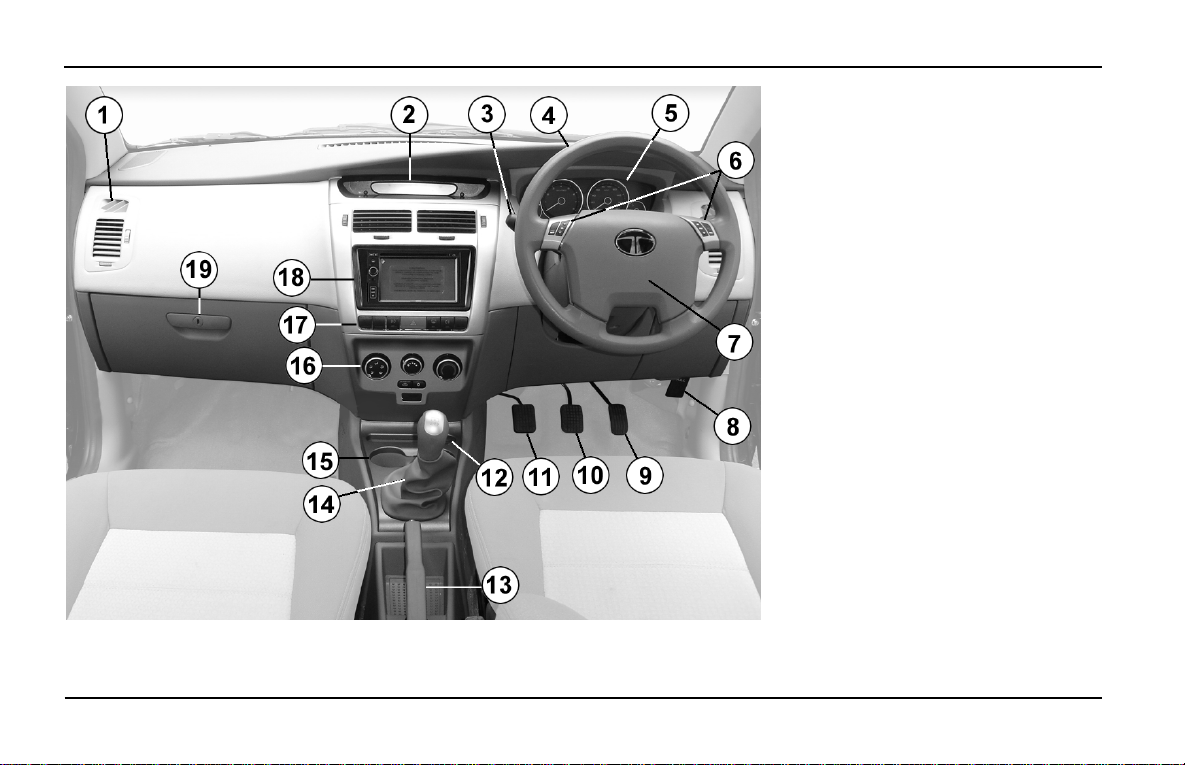
Driving Controls
DRIVING CONTROLS
1. A.C. Air vent (Side)
2. Driver Information System
3. Combi-switch
4. Steering Wheel
5. Instrument Cluster
6. Audio Controls on Steering Wheel
7. Horn pad
8. Bonnet Opening lever
9. Accelerator pedal
10. Brake pedal
11. Clutch pedal
12.Plug Socket
13.Parking Brake lever
14.Gear lever
15. Cup Holder
16.A.C. Controls
17. Facia Switches
18. Music System
19.Glove Box
28
Page 31
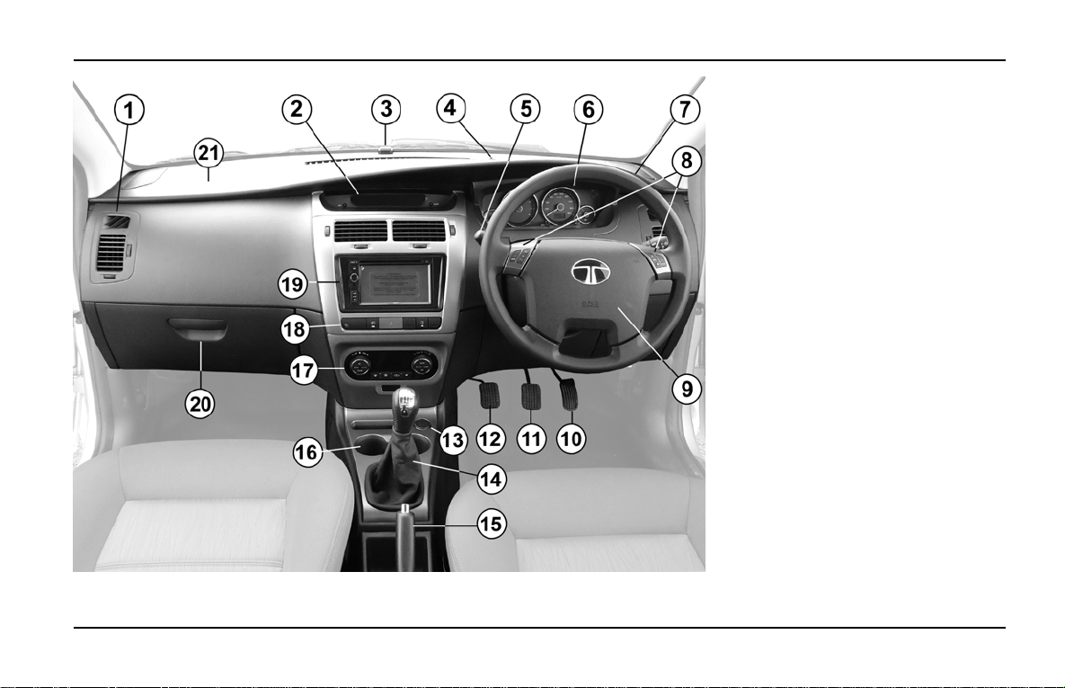
Driving Controls
INDIGO MANZA AT A GLANCE
DRIVING CONTROLS
1. A.C. Air vent (Side)
2. Driver Information System
3. Navigation Sensor
4. Solar Load Sensor
5. Combi-switch
6. Instrument Cluster
7. Steering Wheel
8. Audio Controls on Steering
Wheel
9. Horn pad / Air Bag (DAB)
10. Accelerator pedal
11. Brake pedal
12. Clutch pedal
13. Plug Socket
14. Gear lever
15. Parking Brake lever
16. Cup Holder
17. FATC Control Panel
18. Facia Switches
19. Music System
20. Glove Box
21. Air Bag (Co-driver side) PAB
29
Page 32
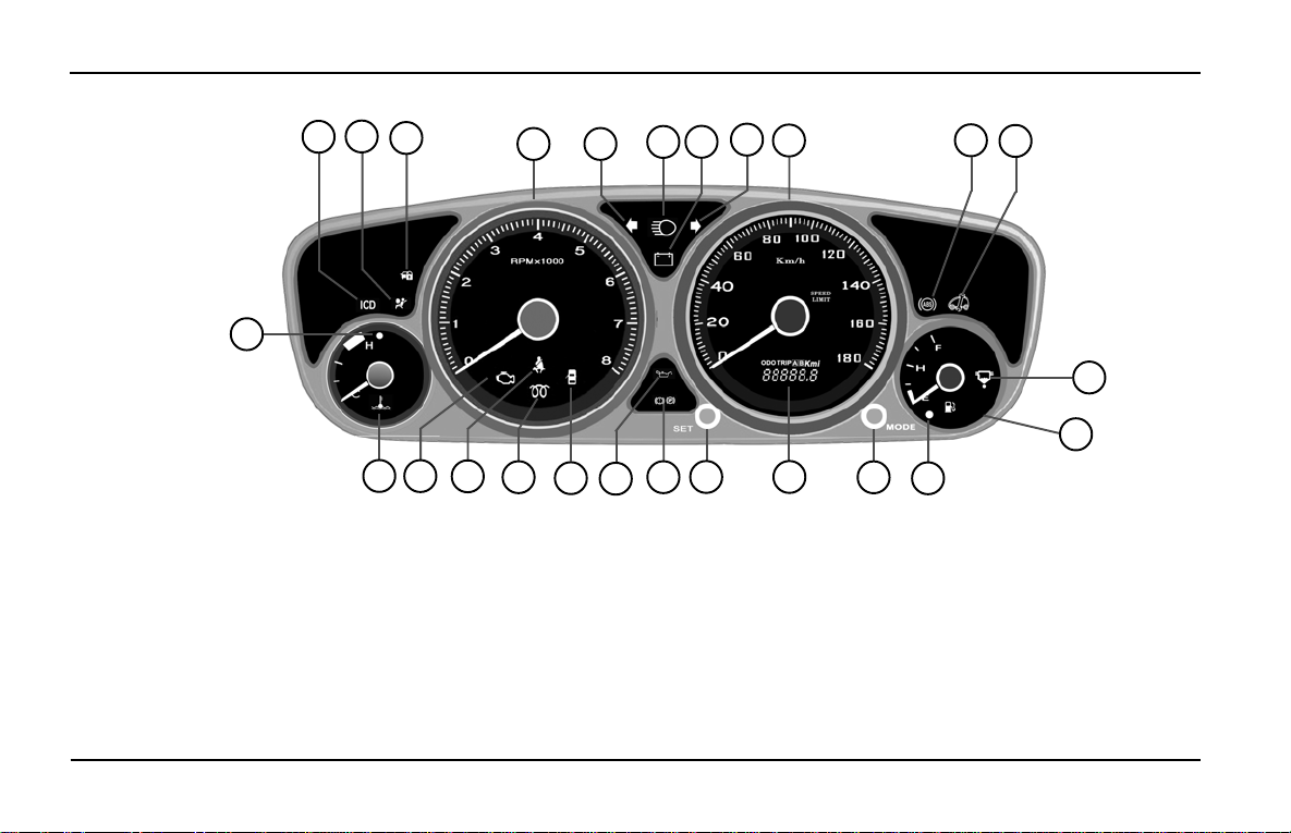
INDIGO MANZA AT A GLANCE
INSTRUMENT CLUSTER
2
1
25
24
3
23
22
4 5
21
20
19
18
Instrument Cluster
7
17
8
9
16
15
6
14
10
11
12
13
1. ICD Indicator (Instrument Cluster
Diagnostic)
2. Air Bag Indicator
3. Immobiliser Indicator
4. Tachometer
5. Turn Signal (Left)
6. High Beam Indicator
7. Battery Charging Indicator
8. Turn Signal (Right)
30
9. Speedometer
10.ABS Indicator (if provided)
11.Service Indicator Lamp (SIL)
12.Water In Fuel Indicator
13. Fuel Gauge
14. Low Fuel Indicator
15. “Mode” knob
16. Multi functional LCD (Digital Display )
17. “Set” knob
18. Parking Brake & Low Brake Fluid
Indicator
19. Low Engine Oil Pressure Indicator
20. Door Open Indicator
21. Glow Plug Indicator
22. Seat Belt Indicator
23. Malfunction Indicator Lamp (MIL)
24. Temperature Gauge
25. High Temperature Warning Indicator
Page 33

Instrument Cluster
THE INSTRUMENT CLUSTER HAS THE FOLLOWING FEA TURES :
INDIGO MANZA AT A GLANCE
• Analogue Gauge: Speedometer, Tachometer / RPM Meter, Fuel Gauge and T emperature Gauge
• LCD Display: Odometer & Trip meter (A & B)
• Tell tales
• Mode & Set knobs
SR. NO. FE ATURES DESCRIPTION
1 Speedometer Vehicle speed (in kmph)
2 T achometer / RPM Meter Engine speed (in rpm)
3 Fuel Gauge Fuel level in tank (Empty to Full)
4 T emperature Gauge Engine temperature
5 Odometer Total distance travelled
6 Trip meter “A & B” Distance travelled on each trip or between fuel fillings
7 Dimmer for cluster & LCD backlighting 4 levels (25%, 50%, 75% & 100%)
8 Over T emperature Warning External Buzzer audio alarm (if fitted)
31
Page 34
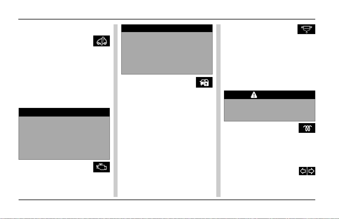
INDIGO MANZA A T A GLANCE
Instrument Cluster
TELL TALES
Service Indicator
Lamp:
This symbol indicates the car’s engine
condition.
1. It comes “ON” when ignition is
switched “ON” and once engine is
cranked, it goes “OFF”.
2. It remains “ON” if there is a problem
in any of the EMS related/ engine
components.
NOTICE
If the Service indicator lamp remains
“ON” when the engine is running, the
engine’s performance deteriorates
marginally & sometimes
significantly . T ake your car to a T A T A
Authorized service centre.
Malfunction Indication
Lamp (MIL):
This symbol comes ON when the
ignition is turned “ON” and goes “OFF”
once the engine is cranked.
32
NOTICE
This symbol will remain “ON” for any
engine related fault, which may
cause increase in emission levels
of the car beyond the regulatory
limit. Take your car to a TATA
Authorized service centre.
Immobiliser
Warning:
This symbol is of a system that
disables engine starting if you do not
use the original key. The user has to
use original key for authentification
and unlocking the car. Refer to
Immobiliser section on page 60 for
details.
Lamp Blink: Car is in immobilised
condition when key is not inserted.
Lamp OFF: Normal condition
(Authenticated user) and engine will
start.
Lamp ON : Problem with key/system.
Take your car to TATA MOTORS
Authorised service centre.
Water in fuel
(in Quadrajet):
This symbol indicates excess water
accumulation in the sedimenter.
It will come ON when ignition is turned
ON and will go OFF in approximately
three seconds. When this lamp
remains ON, water needs to be
drained from sedimenter immediately .
CAUTION
If water is not drained from the
sedimenter, it can cause serious
damage to the fuel injection system.
Glow Plug :
(For Diesel engines only)
This symbol comes ON when the
ignition key is in the ON position.
Engine should be started only after this
indicator goes off.
Turn Signal:
One of these symbols come ON when
the turn indicators is switched ON. Turn
signal lamps can be operated only when
Page 35
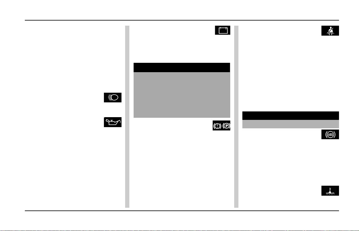
Instrument Cluster
INDIGO MANZA A T A GLANCE
the ignition supply is ON and by using
the turn indicator switch on the combiswitch. The direction indicator arrow (LHS)
and (RHS) on the instrument cluster
flashes along with external indicator lights
as selected.
If one of the external indicator bulbs gets
fused, it is indicated by high frequency
flashing of the bulb of the same side.
High Beam:
This symbol comes ON when the
headlamp high beam is switched ON.
Low Oil Pressure:
When the ignition key is turned to the
IGN position, this symbol lights up and
goes OFF as soon as the required
engine oil pressure is developed after
starting the engine.
If the low oil pressure indicator does
not glow or remains ON with the IGN
ON and engine is running, it indicates
a fault in the electrical circuit /
lubrication system. Take your car to
a T A T A Authorised Service centre.
Battery Charging
Indicator:
This symbol lights up when the IGN
is turned ON and should go OFF after
the engine starts.
NOTICE
If it remains ON while the engine is
running, it indicates that the battery
is not getting charged. Switch off all
unnecessary electrical equipment
and get the problem attended to at
T A T A Authorised Service outlet.
Parking Brake cum Low
Brake Fluid Warning:
This indicator comes ON:
1. When key is turned to IGN position,
it lights up for three seconds and
goes off.
2. When brake fluid level is low.
3. When parking brake is applied and
goes OFF when it is released.
4. When ABS/EBD system has a
fault.
Seat Belt :
This symbol initially flashes when the
ignition is ON and seat belt is not
fastened. It will continue to flash until
the car exceeds a speed of 20 kmph.
After that, it will remain continuously
ON along with a buzzer that will be
audible for approximately for 100
seconds. After that, the buzzer goes
OFF but the indicator continues to
remain ON until seat belts are
fastened.
WARNING
Always wear Seat Belts.
ABS (if provided):
When key is turned to IGN position
this symbol comes ON for two
seconds and goes OFF .
This symbol will come ON if there is a
problem in the ABS working or if the
system has failed.
High Coolant Temperature
Indicator (Red Colour):
This symbol lights up when the
33
Page 36
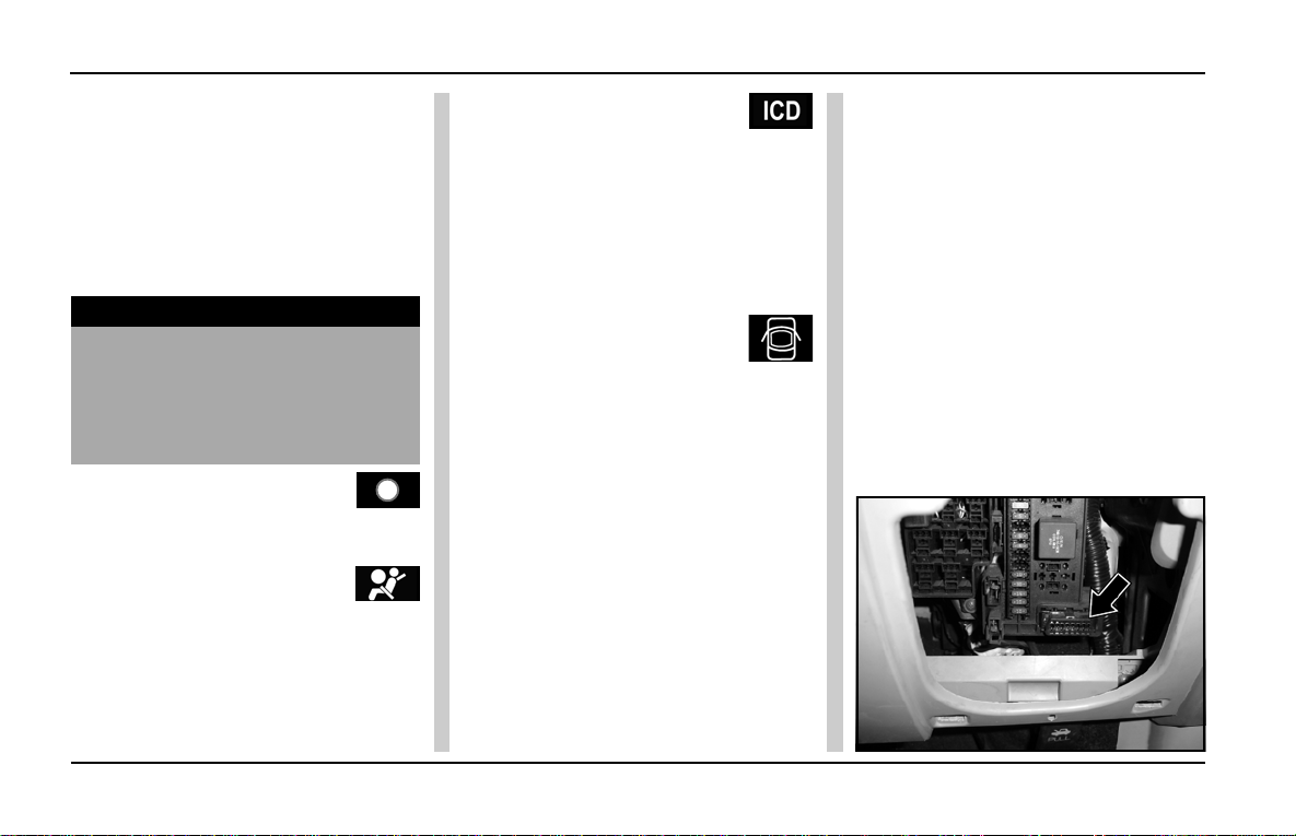
INDIGO MANZA A T A GLANCE
Instrument Cluster
ignition is turned ON. If the engine is
overheating, this indicator blinks
along with a audible buzzer. At this
stage, take the car to the nearest
Authorised Service outlet.This symbol
blinks and audible buzzer sounds
simultaneously when engine coolant
temperature is more than normal.
WARNING
Never remove the radiator pressure
cap from the radiator when the
engine is hot. Do not restart the
engine until the problem has been
duly attended.
Low Fuel (Amber Colour) :
It comes ON when fuel level is low
and needs refilling at the earliest.
Airbag:
The air bag warning symbol comes on
for approximately three seconds
when the ignition is turned ON and
goes OFF. If it remain ON or blinks,
take your car to the nearest Tata
Authorised Service Centre.
ICD Lamp:
This symbol comes ON for
approximately three seconds when
key is turned to IGN position and goes
OFF. If it remains ON or blinks, it
indicates trouble in instrument cluster.
Take your car to a TATA Authorised
Service Centre.
Door Open
Indicator:
This symbol comes ON when the
doors are open or when the doors are
not completely closed.If the driver’s
side door is not closed properly, a
beep will sound for a few seconds
when the ignition is ON.
On Board Diagnostic (OBD)
System:
On board Diagnostics or OBD is an
automotive term referring to a vehicle’s
self Diagnostic and reporting
capability. The OBD system allows
continuous diagnosis of the
components of the vehicle correlated
with emissions. This system warns
the driver, by turning “ON” the
Malfunction Indication lamp (MIL) on
the instrument cluster, when a fault
causes emission levels to increase.
The OBD system also has a
diagnostic connector that can be
interfaced with appropriate diagnostic
tools, which makes it possible to read
the fault codes stored in the Electronic
Control Unit, together with a series of
specific parameters for Engine
operation and Diagnosis. This check
can also be carried out by the traffic
police.
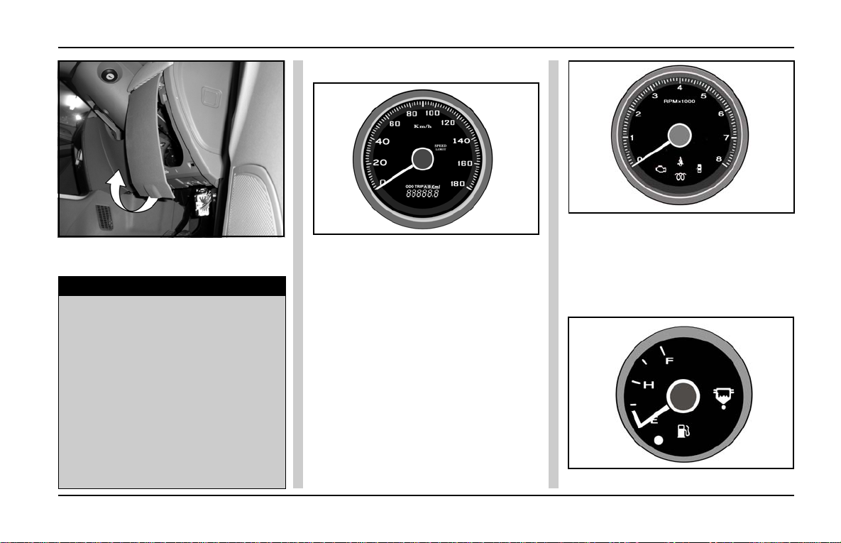
To access the diagnostic connector
(Fig.1),open the fuse box cover (Fig.2)
Fig. 1
34
Page 37
Instrument Cluster
INDIGO MANZA A T A GLANCE
Speedometer:
Fig. 2
which is located on the cockpit at RHS
of the steering wheel.
NOTICE
In case the fault occurs and MIL
comes ON, contact nearest TATA
MOTORS authorized service center.
After eliminating the inconvenience,
to check the system completely,
T A T A MOT ORS authorized service
centers are obliged to run a bench
test and if necessary, road tests
which may also call for a long
journey . The functioning of MIL lamp
may also be checked by the traffic
police using specific devices.
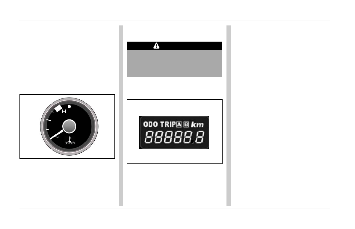
The speedometer indicates the car
speed in km/hr. Driving your car as
per the recomended speeds will help
you get optimum fuel economy and
enhanced engine life.
RPM meter / Tachometer
(if provided):
This meter indicates the engine rpm.
Change the gears at appropriate
engine rpm and speed to get good
fuel economy and driving pleasure.
Do not increase the engine rpm
unnecessarily.
When engine RPM crosses 5000 RPM
(Quadrajet) & 6000 RPM (Safire), the
needle colour changes to RED. A void
over raving the engine.
Fuel Gauge:
35
Page 38
INDIGO MANZA A T A GLANCE
Instrument Cluster
The fuel gauge indicates the
approximate fuel level in the tank.
Refill the fuel tank before the needle
touches the coloured band on the
gauge. At this point, fuel level in tank
is low and it is advised to get fuel filled
immediately.
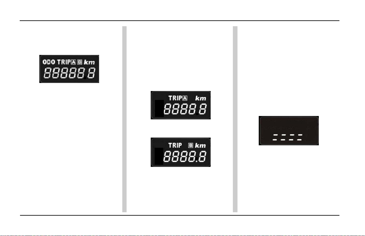
Engine Coolant Temperature
Gauge:
The engine coolant temperature gauge
indicates the approximate coolant
temperature. If the coolant temperature
reading is very high or if the high coolant
temperature indicator comes ON, reduce
the car's speed and switch OFF the AC.
Take the car to an authorised service
station at the earliest.
CAUTION
Overheating of engine can cause
severe damage to the engine parts
and can lead to seizure of engine
parts.
Multifunctional LCD, Odometer,
Dimmer and Tripmeter (A and B):
The instrument cluster’s LCD has a
two line display . The first line displays
ODO, TRIP A, B (in Kms). The second
line displays odometer reading, TRIP
A, B reading as well as brightness
intensity levels.The LCD also displays
Tripmeter A, Tripmeter B and intensity
level when the MODE knob is pressed.
The selection and control of functions
are done through ‘MODE’ and ‘SET’
knobs provided on either side of the
gauge. Refer to table on page 37.
Odometer and T rip meter (on LCD):
The odometer records the total
distance the car has been driven. The
trip meter can be used to measure
the distance travelled on each trip or
between fuel fillings. Keep track of the
odometer reading and follow the
maintenance schedule regularly for
meeting service requirements.
36
Page 39

Instrument Cluster
Y ou can select required function on LCD by using MODE and SET knobs available on cluster , as indicated in the table
below.
Please note that each knob has to be pressed and released to change the function.
Display selection by “MODE” and “SET” knobs :
Sr. No. Indication on LCD With “MODE” knob pressed With “SET” knob pressed
1 Main Odometer Display changes to Trip A ---- 2 Trip meter “A” Display changes to Trip B Resets Trip A distance (Ref. to A on p age 38)
3 Trip meter “B” Display changes to Dimmer, if
cluster Illumination is ON, else Resets Trip B distance (Ref. to B on page 38)
changes to Main Odometer
4 Dimmer Display changes to Main
Odometer Adjusts Dimming level (Ref. to C on page 38)
INDIGO MANZA A T A GLANCE
37
Page 40
INDIGO MANZA A T A GLANCE
Instrument Cluster
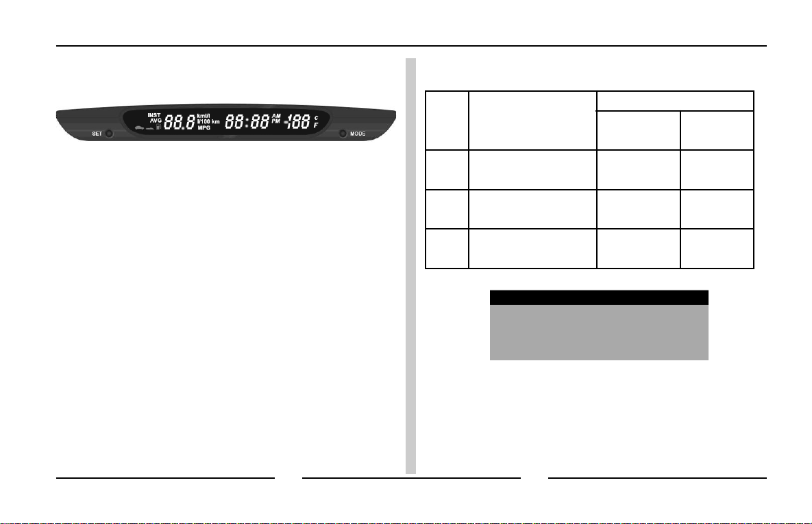
LCD FEA TURES :
A. Multifunction LCD
(as applicable)
Colour : White Text with Black
background.
B. Trip meter (A and B)
Type: 7 segments, 4 1/2 digits
Range: 0 to 1999.9
Resolution : 0.1 km
Trip meter reading shall over flow to
“0.0” after it crosses 1999.9 kms.
TRIP- A (as applicable)
TRIP- B (as applicable)
Trip meter reset
Trip meter (A and B) can be reset by
pressing the “SET” knob slightly longer
when particular Trip meter is selected.
C. Dimmer for Cluster, LCD and
Instrument panel illumination (as
applicable)
Y ou can adjust the LCD brightness
that is best suited to you and it is
shown by the number of Dashes on
the display,
1 2 Dashes => 25 %
2 4 Dashes => 50 %
3 6 Dashes => 75 %
4 8 Dashes => 100 %
After selecting the dimming level, the
display will show the next information
(e.g. Main Odometer) after 20 secs.
Press the “MODE” knob earlier to see
the next information.
38
Page 41

Instrument Cluster
D. Odometer (as applicable)
Type: 7 segments, 6 digits.
Range: 0 to 99999.9
Resolution : 1 km
The Odometer reading will not over
flow to “0.0” when the maximum value
is accumulated, the display will freeze
to maximum value.
INDIGO MANZA A T A GLANCE
39
Page 42

INDIGO MANZA A T A GLANCE
Driver Information System
DRIVER INFORMA TION SYSTEM (as applicable):
The Driver Information System (DIS) is located at centre of
the vehicle cockpit and has the following features:
1. Fuel Computer :
a. Average Fuel Consumption ( For Trip ‘A’ & ‘B’),
b. Range (Distance to Empty) and
c. Instantaneous Fuel Consumption
2. Digital Clock
3. Outside Ambient T emperature
DIS FUNCTIONS
Sr.
No.
1
Fuel Computer
2
Digital Clock
3
Outside Ambient
Temperature
Features
Description
Average Fuel Consumption
(AVG) - For Trip ‘A’ & ‘B’
Range - Distance to Empty
(DTE)
Instantaneous Fuel
Consumption (INST)
12 Hour and 24 Hour
Format
Outside Ambient
T emperature display
with °C and °F
40
Page 43
Driver Information System
Quadrajet, Safire Default Settings (Factory Set)
INDIGO MANZA A T A GLANCE
Sr.
No.
1
2
3
DIS Features
Fuel Computer
Digital Clock
Outside Ambient
Temperature
Whenever battery terminals are
removed, unit returns to factory
setting.
Default Display
Functions Unit
AVG
For Trip -A
12 Hours AM
OA T C
NOTICE
km/l
41
Page 44
INDIGO MANZA A T A GLANCE
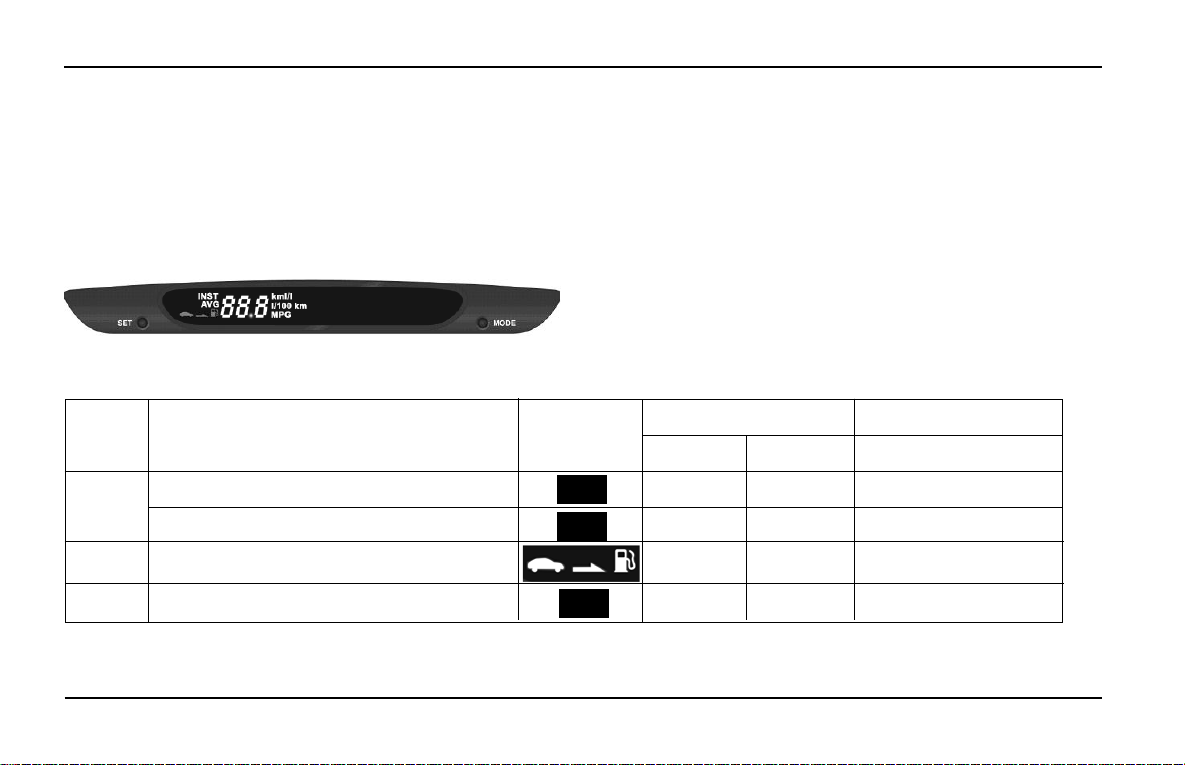
Fuel Computer
Fuel Computer information is available on DIS, as can
be seen from figure below. Three types of information
are available, which can be user selected through
"MODE" and "SET" knobs provided.
Refer to “Knob Function” on page 48.
Driver Information System
Sr. No.
1
2
3
42
Function Text on
Distance Unit as km
Display
Average Fuel Consumption For T rip ‘A ’ km/l l/100km
Average Fuel Consumption For Trip ‘B’ km/l l/100km
AVG MPG
AVG MPG
Distance to Empty (Range)
Instantaneous Fuel Consumption km/l l/100km
INST
Option - 1 Option - 2
km -
Distance Unit as Mile
Option
Miles
MPG
Page 45
Driver Information System
INDIGO MANZA A T A GLANCE
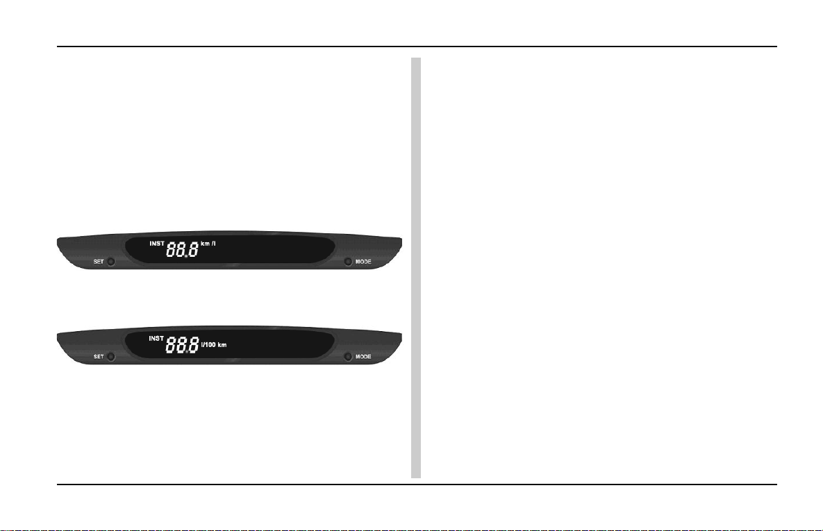
Instantaneous Fuel Consumption (INST):
Updates display "Instantaneous Fuel Consumption" at
regular time intervals.
Instantaneous Fuel Consumption display is available in
"km / l" or "l / 100 km" which can be user selected through
"MODE" and "SET" knobs provided.
Refer to “Knob Function” on page 48.
Instantaneous Fuel Consumption display in km / l
Instantaneous Fuel Consumption display in l/100 km
DIS displays “Instantaneous Fuel Consumption data” only
when the following conditions are met -
DIS displays “- - km/l” when ign on & engine is off
DIS displays “0.0 km/l” when ign on & engine is on
DIS displays “Instantaneous Fuel consumption data ”only
when the below conditions are met:
A. Vehicle speed should be more than 10kmph.
B. Vehicle travelled dist ance should be more than 20meters.
Display Range: 0.0 to 99.9 (km/l or l/100km)
Resolution: 0.1 (km/l or l/100km)
43
Page 46
INDIGO MANZA A T A GLANCE
Driver Information System
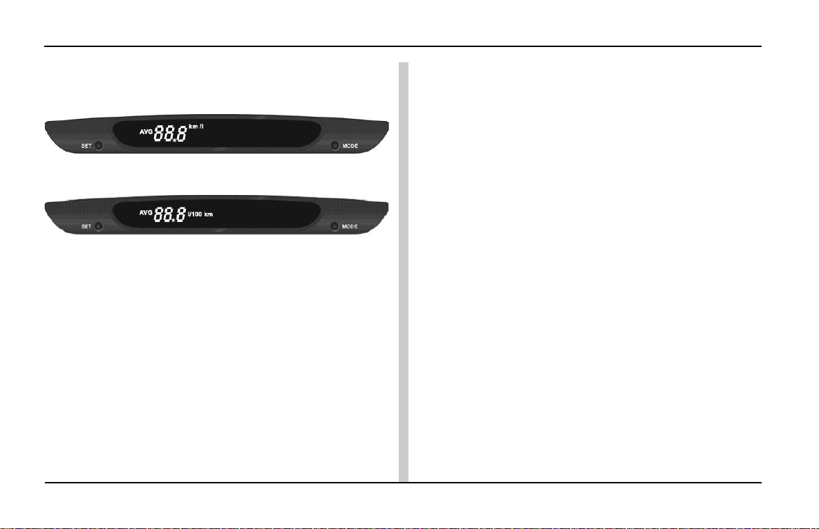
Average Fuel Consumption (A VG):
Average Fuel Consumption display in km / l
Average Fuel Consumption display in l/100 km
The display will show the value of average fuel consumption
since the last reset.
Average Fuel Consumption display is available in “km/l” or
“l/100km” which can be selected by user by using “Mode
& Set” switches.
Average Fuel consumption will get updated for every
10secs interval.
The A verage Fuel Consumption data can be reset manually
through “Set” switch provided in the cluster
After resetting the Average fuel consumption the display
will indicate 0.0 and then will show a new average fuel
consumption value after driving for some distance.
If previous data exist DIS will update the display once engine
speed is >0rpm.
Display Range: 0.0 to 99.9 (km/l or l/100km)
Resolution: 0.1 (km/l or l/100km)
Refer to “Switch Function” on page 47.
44
Page 47
Driver Information System
INDIGO MANZA A T A GLANCE
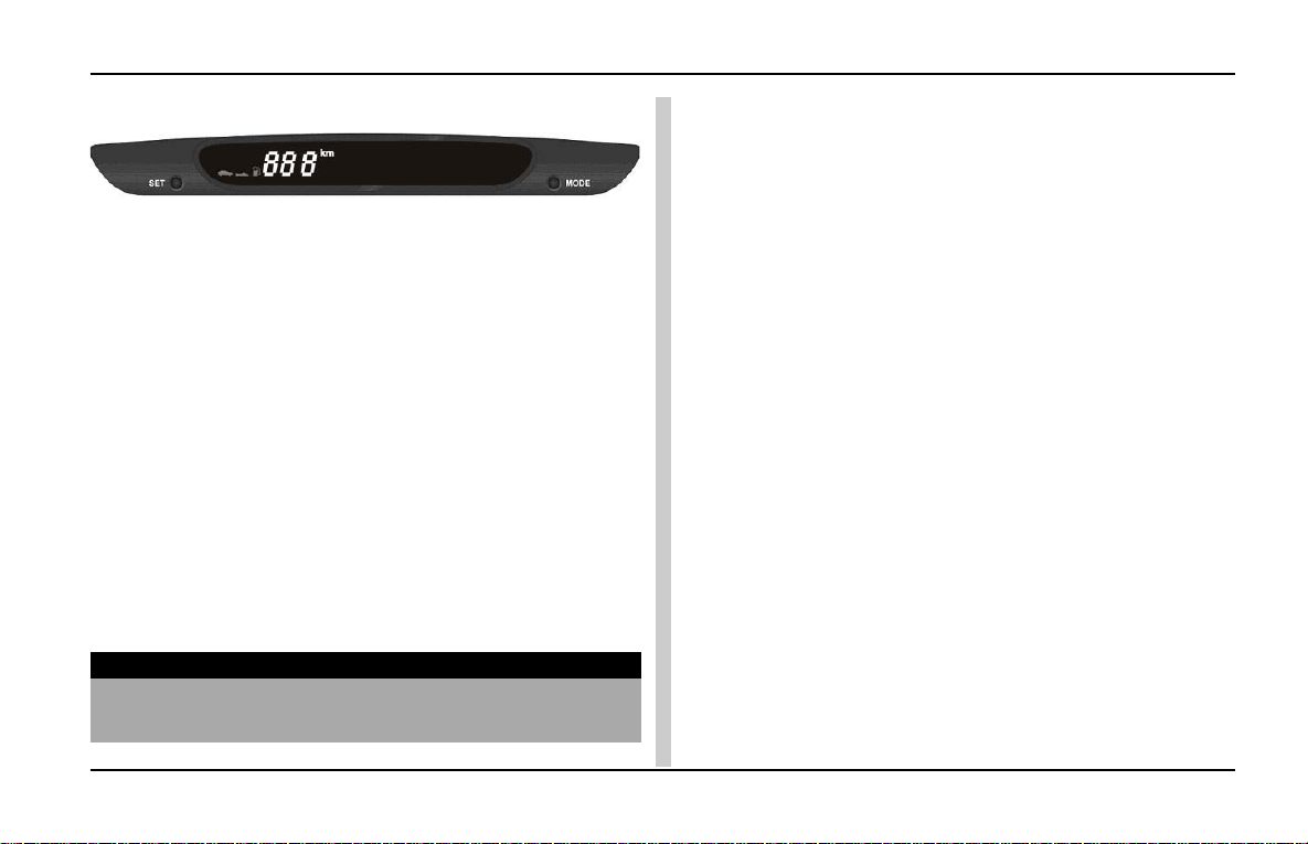
Distance to Empty (DTE):
Distance T o Empty (Km)
This feature shows the estimated distance user can drive
with the remaining fuel in the tank. The value is calculated
based on fuel economy user have achieved over few
hundred kilometres or miles.
DIS displays actual DTE at every Ignition on cycle.
DTE is calculating using a running average fuel economy
which is based on recent driving history for few hundred
km. This running average fuel economy value is not same
as average fuel economy display .
This value tends to vary with change in drive pattern, vehicle
speed, Traffic condition and different road conditions.
Display Range: 0 to 999 km
Resolution: 1 km
NOTE
To get actual DTE value after fuel filling customer has
do the ignition OFF to ON
Whenever battery terminals are removed, units return to
default factory setting. (All data’s will get reset). Again it
shows the data on display after some distance travelled
and data’s will get stabilized after some few km depending
upon the driving pattern.
45
Page 48
INDIGO MANZA A T A GLANCE
Digital Clock
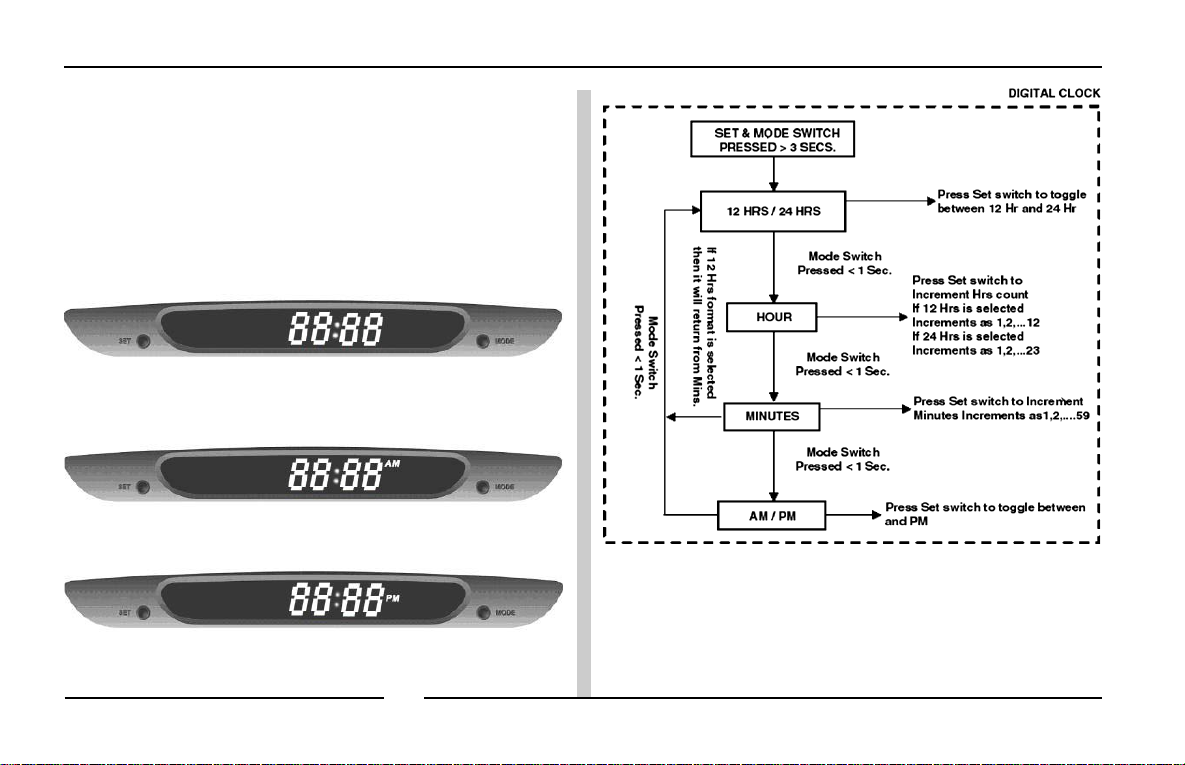
This feature has 24 hour or 12 hour display format,
AM/PM indication is applicable for 12 hour clock function
only , as can be seen from the adjoining figure, which can
be user selected through "MODE" & "SET" knobs
provided.
Digital Clock Display
Digital Clock AM Setting
Digital Clock PM Setting
Driver Information System
46
Page 49
Driver Information System
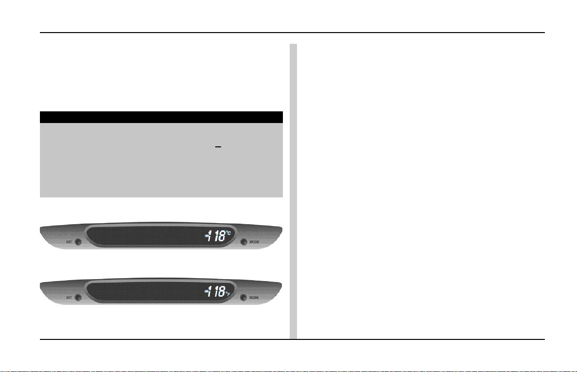
Outside Ambient Temperature Display:
Outside Ambient Temperature can be seen with °C or °F
unit, which can be selected by user by using “MODE”
and “SET” knobs.
Resolution: 1°C or °F
NOTE
The displayed “Outside Ambient T emperature” value may
not be accurate when Vehicle speed is < 30 km/h due
to engine heat, exhaust from surrounding vehicles and
heat reflection from road. The IC delays the OA T display
update until it reaches the correct outside temperature.
This may take several minutes.
Outside Ambient Temperature (Display in °C)
Outside Ambient Temperature (Display in °F)
INDIGO MANZA A T A GLANCE
47
Page 50

INDIGO MANZA A T A GLANCE
Driver Information System
SWITCH FUNCTIONS :
User can select required function, using switches available on DIS, as indicated below. Please note that each switch has
to be released & pressed to change the function.
DISPLAY SELECTION BY “MODE & SET” SWITCHES :
Sr. Indication On Indication on With “Mode” switch With “Set” switch
No. instrument DIS LCD pressed on DIS pressed on cluster
cluster LCD
1 Odo meter Average Fuel Changes display to Range -
Consumption A (Distance to Empty)
2 Trip meter A Average Fuel Changes display to Range Resets Average Fuel
Consumption A (Distance to Empty) Consumption data for Trip A
3 Trip meter B Average Fuel Changes display to Range Resets Average Fuel
Consumption B (Distance to Empty) Consumption data for T rip B
4 - Range Changes display to -
Distance to Empty Instantaneous Fuel Consumption
5 - Instantaneous Changes display to Average
Fuel Consumption fuel consumption for trip A or
Trip B based on Instrument
cluster display .
48
Page 51
Driver Information System
INDIGO MANZA A T A GLANCE
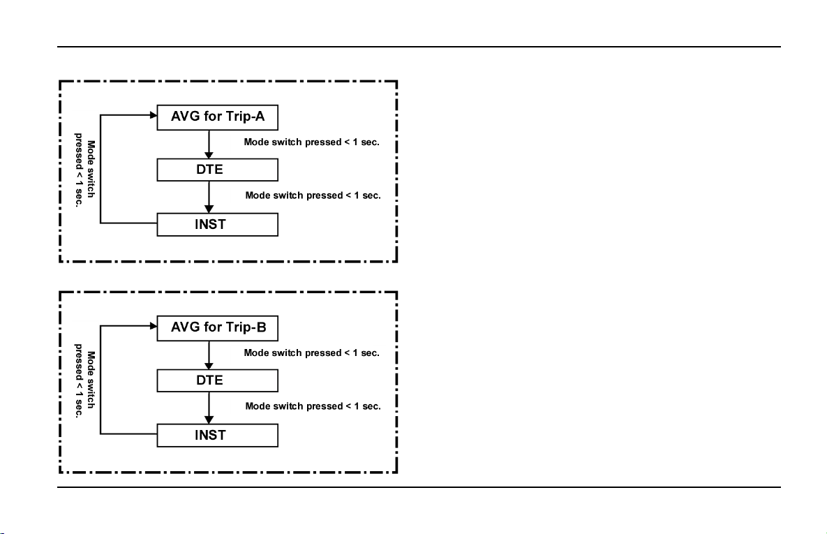
A. Instrument Cluster Display on Odo OR Trip-A :
B. Instrument Cluster Display on Trip-B :
NOTE : Use of ‘MODE & SET’ switches - Recognized
as single key press, until it is released.
49
Page 52
INDIGO MANZA A T A GLANCE
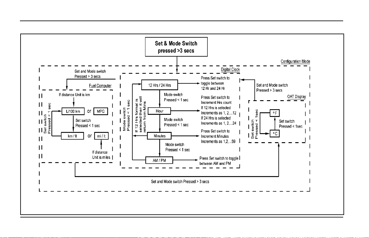
Flow chart for using “MODE” and “SET” knobs
Driver Information System
50
NOTE : 1. If no switch pressed > 10 secs ........ Save & exit
2. If Set & Mode switch pressed < 1 secs ........ Save & exit
Page 53
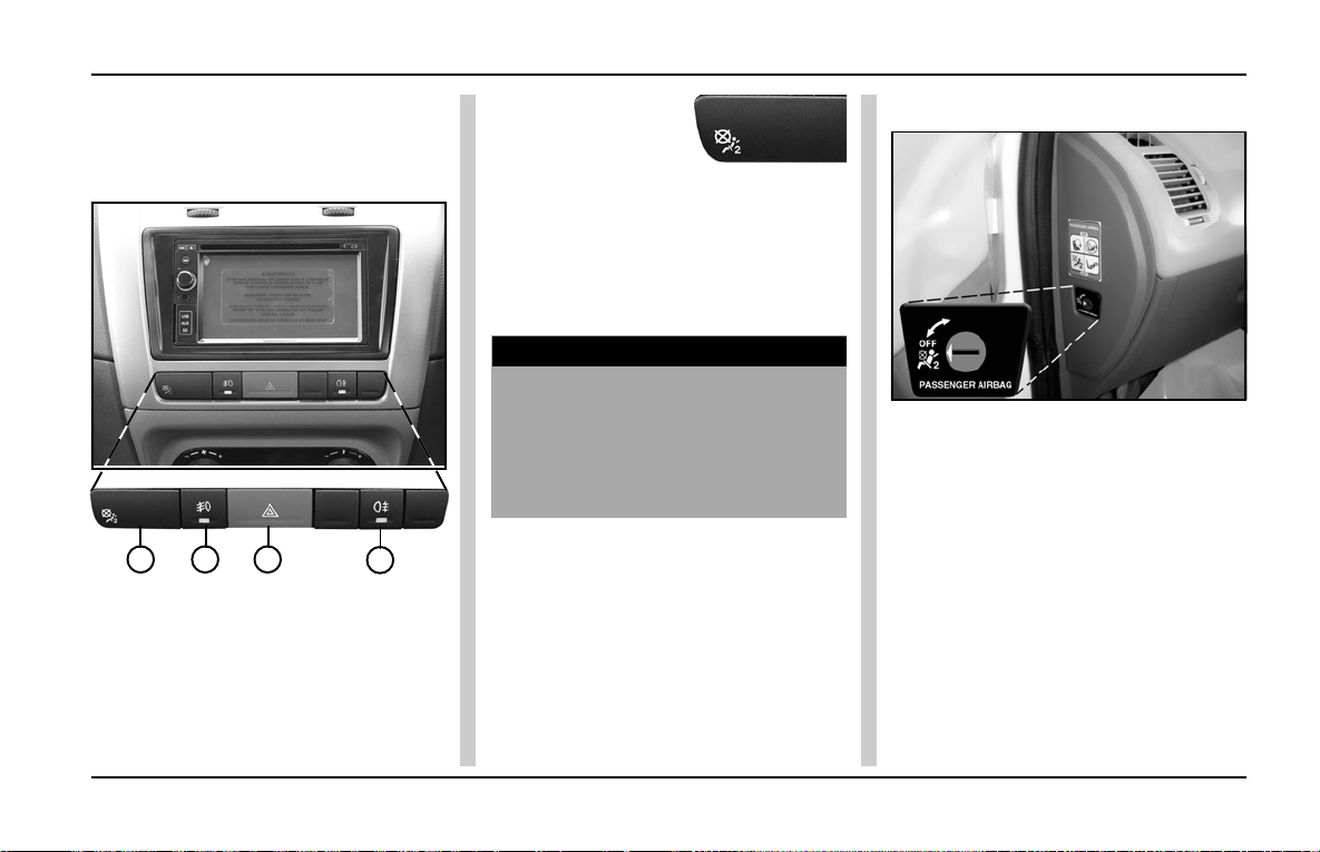
Facia Switches
INDIGO MANZA A T A GLANCE
FACIA SWITCHES/INDICA TORS :
Five operating switches are provided
on the facia.
1 2 3
1. Passenger Airbag Indicator
2. Front Fog Lamp Switch
3. Hazard Warning Switch
4. Rear Fog Lamp Switch
4
Passenger Airbag
Indicator:
The Passenger Airbag Indicator,
indicates whether the passenger
airbag is activated or de-activated.
The Passenger Airbag Indicator comes
ON when the Ignition is turned ON.
WARNING
Ensure that the passenger airbag
indicator is always ON when there
is a passenger travelling.
Ensure that the passenger is
always using the seatbelt.
Passenger Airbag (P AB) Switch :
Passenger Air Bag (PAB) switch is
provided on the left side of dashboard
and it should always be ACTIVE. If in
case the front passenger seat is
unoccupied, the PAB may be
prevented from deploying by turning
the P AB switch to INACTIVE by using
the ignition key .
51
Page 54
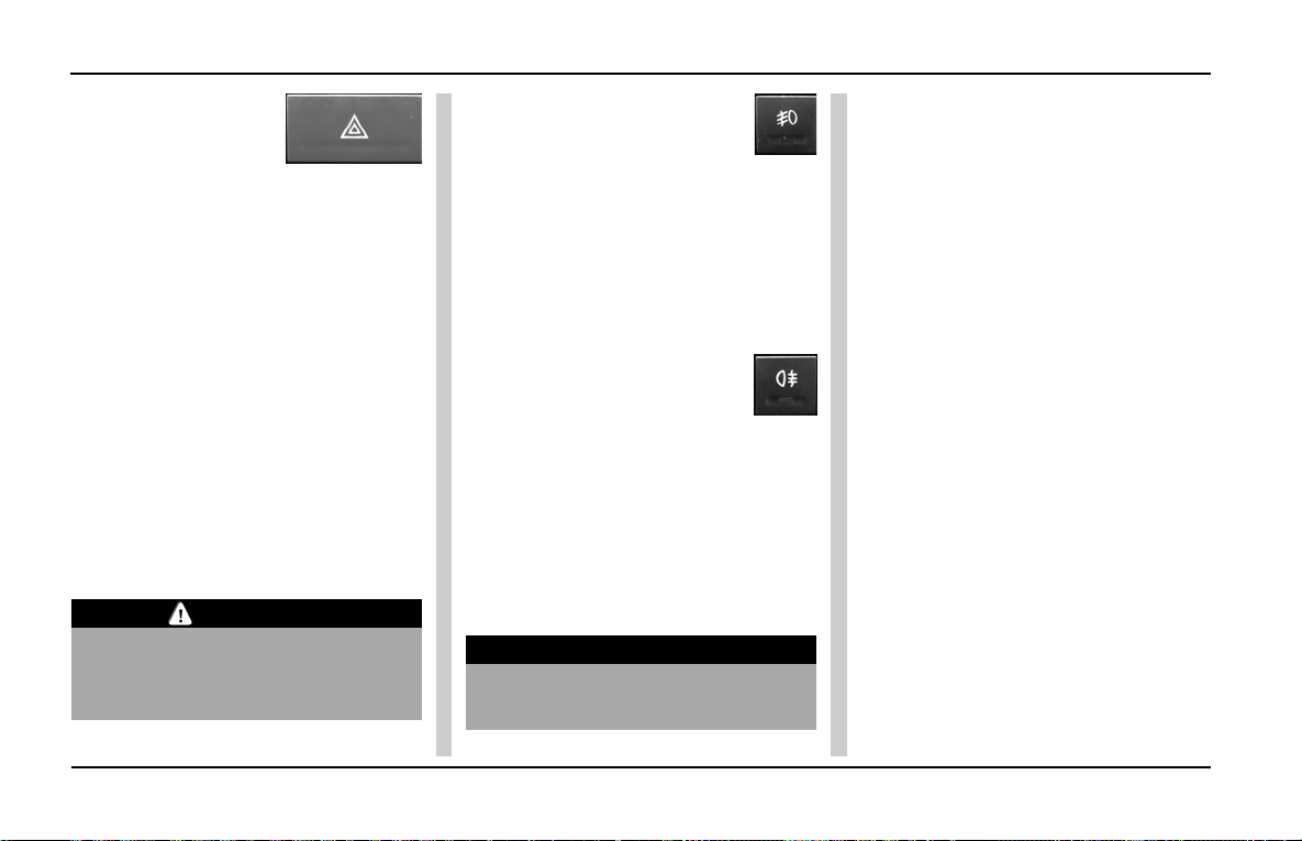
INDIGO MANZA A T A GLANCE
Facia Switches
Hazard Warning
Switch:
Hazard warning is used in case of a
breakdown especially during night and
the car has to be parked at the side of
the road. This switch can also be used
when the car is operated in adverse
conditions.
This switch can be operated without
Ignition ON. Press hazard warning
switch to turn ON all outside turn
signal lights and indicators on cluster
will flash simultaneously to warn the
other road users about hazardous
condition of the car. Press the switch
again to turn OFF the hazard indicating
function.
CAUTION
Ensure that all turn signal indicators
are working properly. Replace the
bulb if found fused.
Front Fog Lamps :
( Unlatched switch)
Fog lamps are provided on front
bumper to improve visibility in foggy
weather or during heavy rains. The
front fog lamps can be switched ON
with ignition ON and parking lamp ON
and can remain on till the parking lamp
is switched OFF.
Rear Fog Lamps :
(Unlatched switch)
Fog lamps are also provided on tail
lamp cluster to improve visibility and
warning in foggy weather or during
heavy rains. The rear fog lamps can
be switched on with parking lamp and
front fog lamps ON and can remain
ON till the parking lamp is switched
OFF.
NOTICE
Use only during foggy conditions or
heavy rains if required.
52
Page 55
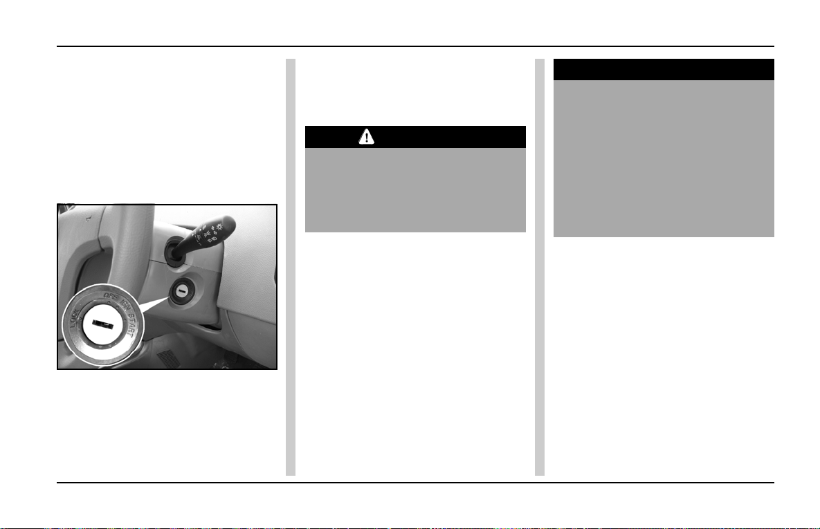
Steering Lock cum Ignition Switch
INDIGO MANZA A T A GLANCE
Steering Lock cum Ignition Switch:
Key of ignition switch is common for
door lock, steering lock and glove box
lock.
The ignition switch is on the right side
of the steering column. It has four
positions. Turn the key clockwise for
further functions.
LOCK - Steering Locked
OFF - ‘KEY IN’ position.
I GN - All electricals ON
STAR T - Engine crank
LOCK :
Y ou can insert or remove the key only
in this position. The steering column
is locked when the key is removed.
CAUTION
Do not remove the key while
driving. It will lock the steering and
can cause loss of control. Remove
the key only when the car is
parked.
OFF (key IN) :
By turning key to OFF (key in)
position, ‘KEY IN’ driven load like
music system will be ON.
IGN :
All electricals and accesories ON.
ST ART :
Turn the key further clockwise to the
ST ART position (spring loaded) to start
the engine. As soon as the engine
starts, release the ignition key to ON
position. While cranking, all
accessories will be momentarily OFF .
NOTICE
Do not crank the engine for more
than 10 secs. continuously . If the
engine does not start, wait for 30
secs. before cranking it again.
Release the key immediately after
starting the engine. If the key is
not released, the starter motor/
flywheel ring gear may get
damaged.
By turning the ignition key from IGN
position to OFF position, engine can
be stopped.
53
Page 56
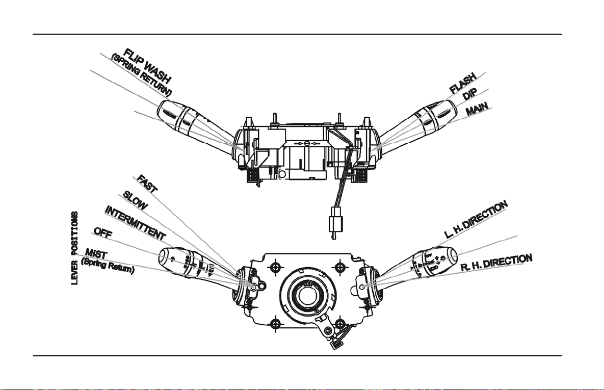
INDIGO MANZA A T A GLANCE
Combi- Switch
COMBINA TION SWITCH
Top View
54
Front View (from Driver’s seat)
Page 57
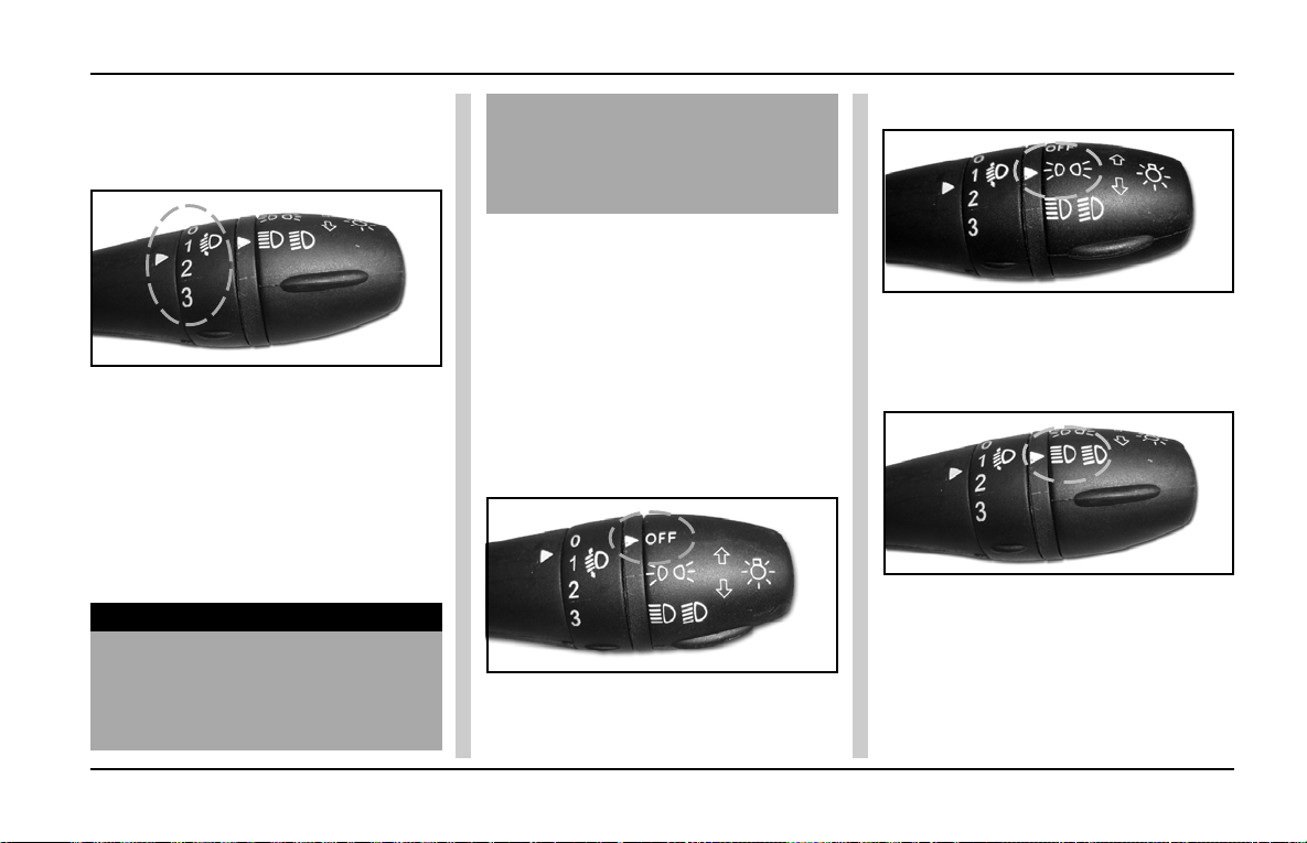
Combi-Switch
INDIGO MANZA A T A GLANCE
A) RIGHT HAND ST ALK
1. Head lamp leveling rotary
switch:
Inner rotary switch on right hand stalk
is provided for head lamp leveling.
Setting is done by rotating the knob
to select one of the three level
positions depending upon the loading
of the car. Head lamp leveling can be
done with head lamp in Low Beam and
in ON position.
NOTICE
Setting should be done only when
car is stationary.
Since the leveling switch takes care
of headlamp focus pattern under
varying load conditions, it is
advisable to select the correct
position before starting a trip
(depending on load).
2. Light stalk:
Outer rotary switch on right hand stalk
is provided for selecting Position or
Head lamp High/Low beam. It operates
with Ignition switch in IGN position.
a) Head / Position lamp OFF.
Head lamp, Position (Parking) lamp
and tail lamp will be OFF in this
position.
b) Position lamp in ON.
Position (Parking) lamp and tail lamp
will be ON in this position.
c) Head / Position lamp ON.
Head lamp, Position (Parking) lamp
and tail lamp will be ON in this position.
Toggling the lever (Stalk) in upward
direction changes the Low beam to
High beam and vice versa.
55
Page 58
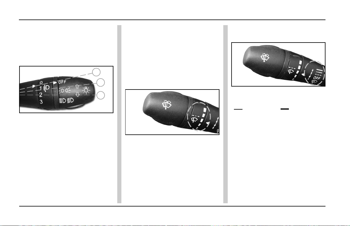
INDIGO MANZA A T A GLANCE
Combi Switch
For High beam flash, pull the lever
halfway. For keeping in High beam
position pull up the lever further up to
latch.
3. Light stalk (T urn Indicator):
Left turn
C
B
A
Right turn
Push the stalk upwards for changing
lane or turning to Left and downwards
for changing lane or turning to Right
according to requirement. It has three
positions.
A) Right turn indicator
B) Neutral position
C) Left Turn (Self cancellation / Manual
return type)
Lane change option When changing lanes, hold the stalk
half way towards A or C (right of left).
By doing so, the turn indicators flash
to give lane change indication. once
released, the stalk returns to its
original position.
2. Intermittent front wiper delay:
Inner rotary switch on left hand stalk
is provided for intermittent front wiper
delay . The switch has five delay timers
for intermittent function.
3.Front windshield-Wipe and
Wash rotary switch:
Pull the stalk upwards to operate
intermittent wipe (- - -), Slow wipe
( ) or fast wipe ( ). Pull the stalk
down for wipe and wash. Pull towards
driver for Flick Wipe (spring return).
After wash function is activated, there
will be three wipes of wiper. There will
be one more wipe after five seconds
to clean traces of water on wind
screen.
56
Page 59
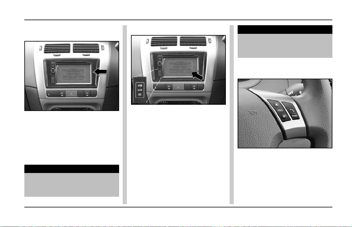
Touch Screen Music & Navigation System and USB/AUX Port
INDIGO MANZA A T A GLANCE
Touch screen Music and Navigation System :
A touch screen music system and
navigation system is provided on the
centre console above FA TC p anel.
To operate this system, please
refer operator’s handbook, which is
provided alongwith the Owner’s
Manual.
NOTICE
Do not cover navigation sensor, this
may lead to improper functioning of
navigation system.
USB/AUX PORT :
USB and AUX Port s are provided on
the Music System on the centre
console.
Functions :
USB port : You can attach
external memory devices like memory
sticks / Pen Drives, I-Pods for playing
music tracks stored in these devices
through the car’s music system.
AUX port : The AUX port is provided
to connect Audio input devices for
playing music tracks stored in
thedevices through car’s speakers.
NOTICE
The video input can also be
connected to AUX port (For specific
variants only) for playing video files.
Steering Wheel Switches (RHS):
(As applicable)
SEEK – T o change radio channels or
to select a song from a CD.
MODE – To pick up an in-coming
phone call as well as to change the
audio source (USB, AM, FM, CD).
57
Page 60
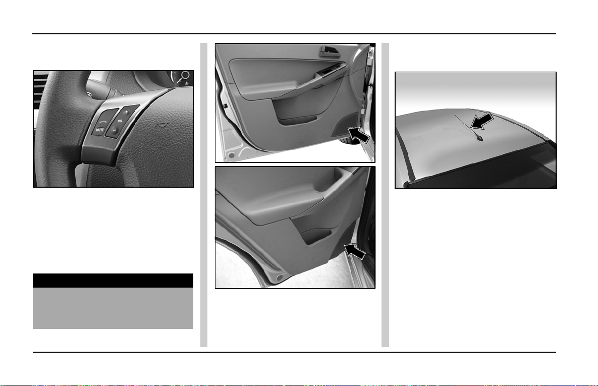
INDIGO MANZA AT A GLANCE
Music System & Antenna
Steering Wheel Switches (LHS):
(As applicable)
VOL (V olume): T o increase / decrease
volume of music system / radio.
MUTE: To reject or hang up a phone
call. It is also used to silent the volume
of music system / radio.
NOTICE
For more information, please refer
to the Music System Manual
provided.
Antenna: Antenna is located on the
roof, above the front windshield glass.
Antenna
Speaker Location on doors
For operation and more information of
music system please refer
manufacturer’s manual.
58
Page 61
Heating, Ventilation & Air Conditioning
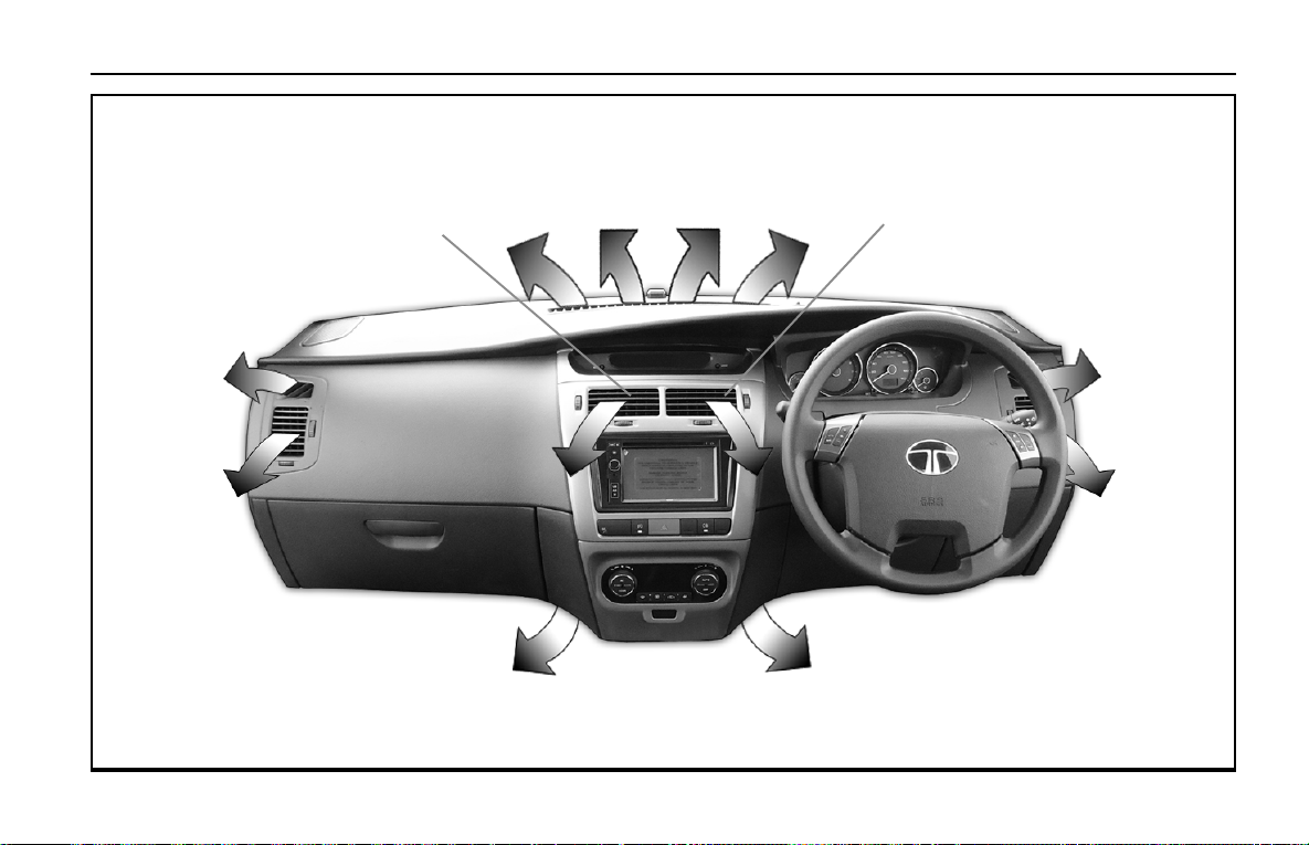
AIR FLOW PATTERN
INDIGO MANZA A T A GLANCE
Side Air
Vents
Side Air
Vents
Central
Air Vents
Towards
Foot Board
Demisting Vents
Central
Air Vents
Side Air
Vents
Side Air
Vents
Towards
Foot Board
59
Page 62
INDIGO MANZA A T A GLANCE
FATC
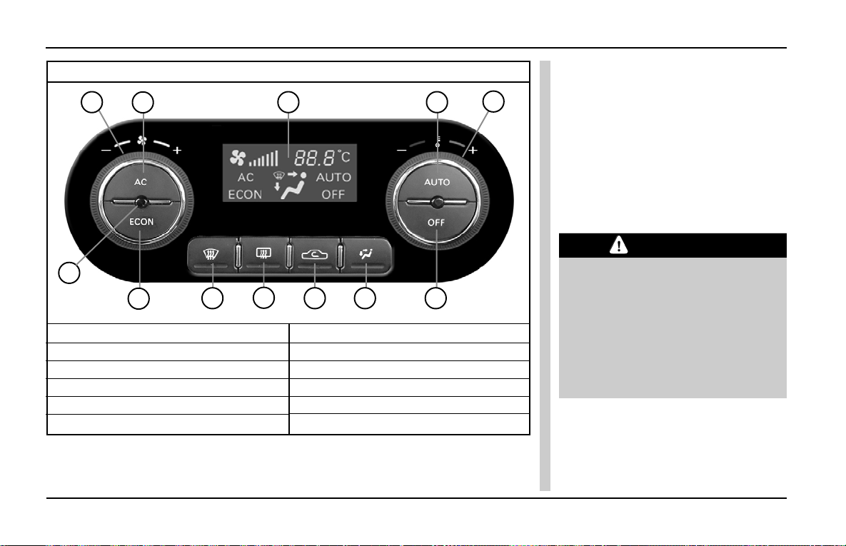
FA TC - FULL Y AUTOMA TIC TEMPERA TURE CONTROL
1
2
12
3 4
1. BLOWER SPEED CONTROL KNOB
2. AC COMPRESSOR ON/OFF BUTTON
3. ECON (ECONOMY MODE) BUTTON
4. MAX DEFROST BUTTON
5. REAR WINDOW DEMISTER BUTTON
6. FRESH AIR / RECIRCULATION BUTTON
5
811
6
7. AIR DISTRIBUTION (MODE) BUTTON
8. AUTO ON SELECTION BUTTON
9. TEMPERATURE CONTROL KNOB
10. “OFF” BUTTON
11. DISPLAY
12. IN CAR SENSOR
7 10
FATC - FULLY AUTOMATIC
TEMPERATURE CONTROL : (IF
9
PROVIDED)
GENERAL DESCRIPTION :
FATC system controls the in-cabin
Temperature of the vehicle
automatically and provides maximum
passenger convenience regardless of
outside weather conditions.
CAUTION
If the display flashes ‘ERR’ in
periodic pattern (Display will show
‘ERR’ for 5 sec. and set
temperature for 30 sec.),It indicates
FA TC malfunctioning. Switch over to
manual mode and contact TATA
MOTORS authorized service
station.
60
Page 63
FATC
INDIGO MANZA A T A GLANCE
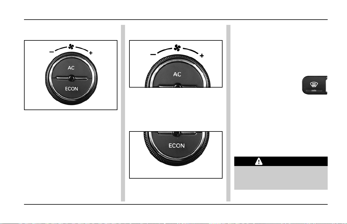
1. BLOWER SPEED CONTROL
KNOB :
A. Rotate the knob clockwise to
increase the blower speed up to
MAX 7 speed, where as anti-
clockwise would reduce the speed
up to ‘SPEED 1’.
B. In ‘AUT O’ mode, the F A TC system
will regulate the blower speed
automatically.
2. AC COMPRESSOR ON / OFF
BUTTON :
Press the AC compressor ON/OFF
button to turn the air conditioning ON
or OFF. You will see AC text on the
display , when AC is ON.
3. ECON A.C. :
During ECON AC operation, the
system automatically cuts off
compressor at a higher temperature
than normal AC. The operation can be
used during mild weather conditions
for better fuel efficiency . Comfort level
may be compromised during this
operation. By pressing ECON button
text will be displayed on display .
4.MAX DEFROST
BUTTON :
A. This button directs the main airflow
towards windscreen for faster
defrosting.(It also overrides any
mode selection you may have
made.)
B. When you turn off the button, the
system returns to its former
settings.
CAUTION
For your safety make sure you have
a clear view through all the windows
before driving.
61
Page 64
INDIGO MANZA A T A GLANCE
FATC
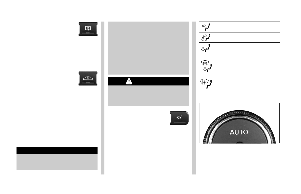
5.REAR WINDOW
DEMISTER BUTTON:
A. This button turns the rear window
demister ON or OFF .
The system automatically
deactivates after 15 min of
continuous operation.
6. FRESH AIR /
RECIRCULA TION
BUTTON:
A. When the recirculation Button or
LED is switched ‘ON’, air from the
vehicle’s interior is sent through out
the system.
B. When the recirculation button is
switched off, air is brought in from
outside of the vehicle (fresh mode).
Whenever discomfort is felt, switch
to fresh air mode.
NOTICE
The out side air intakes for the
climate control system are at the
62
base of windscreen. Keep this area
clear from leaves and other debris.
The system should be used with
recirculation air mode for faster heat
up and cool down, however keeping
the system in recirculation mode,
particularly with AC OFF , can cause
the windows fog up.
CAUTION
It is recommended to run the vehicle
in re-circulation mode to avoid
clogging of air filter
7. AIR DISTRIBUTION
(MODE) BUTTON :
A. In AUTO mode, the FATC system
will regulate the mode
automatically. However user
override is possible with the use
of MODE button to select the
desired airflow mode. Each time
you press the MODE button, the
display shows the mode selected.
Towards face
Towards face and leg
Towards leg
Towards leg & windshield - demist
or defrost (Recommended for
clearing mist on windshield ) front air demist.
Towards windshield (defrost)
(Recommended for clearing heavy
fog or snow)
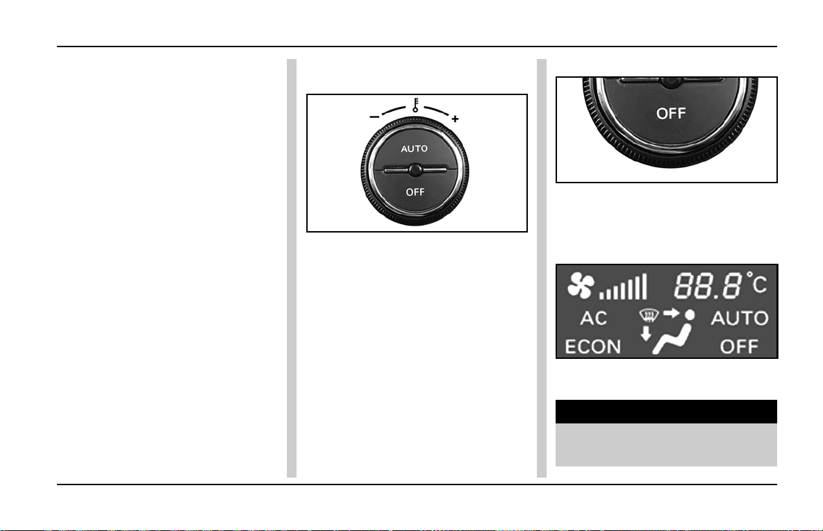
8. AUTOMA TIC OPERATION :
To put the automatic climate control
in fully-automatic mode:
A. Press the ‘AUTO’ button.
B. Set the desired temperature by
turning temperature control knob.
Page 65
FATC
INDIGO MANZA A T A GLANCE
The display will show all the
functions during ‘AUTO’ mode.
C. The system automatically selects
the proper mix of conditioned and/
or heated air that will , as quickly
as possible, raise or lower the
interior temperature to your
preference.
D. When you set the temperature to
its lower limit (Lo) or its upper limit
(Hi), the system runs at full cooling
or heating only . It doesn’t regulate
the interior temperature.
Semi-automatic Operation :
You can manually select various
functions of the climate control
system when it is in fully automatic
mode. All other features remain
automatically controlled .Making any
manual selection causes the word
‘AUTO’ in the display to go OFF and
overridden setting is displayed.
System will remain in semiautomatic
mode till ‘AUTO’ is re-pressed.
9. TEMPERATURE CONTROL
KNOB:
Turning the temperature control knob
clockwise increases the temperature
of the air . The desired temperature will
be increased by steps of 0.5ºC. User
can select temperature range from
18ºC to 30ºC. Where as the anticlockwise direction decreases the
temperature.
When you set the temperature to its
lower limit (Lo) or its upper limit (Hi),
the system runs at full cooling or
heating only. It doesn’t regulate the
interior temperature.
10. “OFF” BUTTON:
Press the OFF button to switch OFF
The system. OFF will be displayed on
the display .
11. DISPLAY :
Settings done by user or AUTO mode
functions are displayed on screen.
NOTICE
HVAC system is fitted with three
Sensors .
63
Page 66
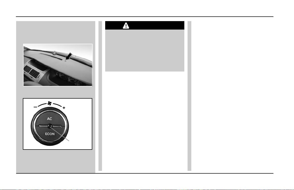
INDIGO MANZA A T A GLANCE
FATC
1. A solar sensor on top of the
dashboard on the right side of
defroster grill.
2. In-car sensor on control panel.
IN CAR
SENSOR
3. Outside Ambient Temperature
(OAT) sensor located under the
front grill / front bumper.
CAUTION
1. Do not cover or spill any liquid on
sensors.
2. Do not cover sensor, this may
cause the sensor to malfuction.
This may lead to FATC not
functioning to desired level.
If you parked your car under sun ,
you can cool it down fast by
following the steps given below :
A. Start the engine
B. Turn on A/C by pressing the button.
Make sure the temperature control
is set to maximum cool.
In case of FATC set temperature
to ‘Lo’ mode.
C. Set the fan to maximum speed. (for
ETC ,manual HV AC variants)
D. Open windows half , set air
direction towards face and fresh air
mode.
E. When the interior has cooled down
to a more comfortable level, close
windows and set the controls as
required in normal cooling, with
recirculation mode ON.
64
Page 67
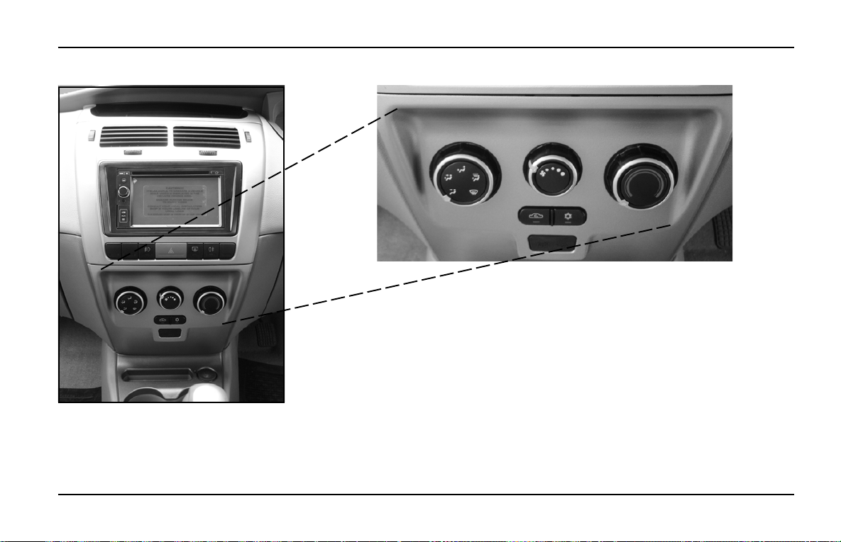
Heating, Ventilation & Air Conditioning
HEATING, VENTILATION & AIR CONDITIONING (IF PROVIDED)
INDIGO MANZA A T A GLANCE
Centre Console
A
C
B
ED
A - Air flow Direction Control Knob
B - T emperature Control Knob
C - Blower Speed Regulation Knob
D - A.C. ON/OFF Switch
E - Air Recirculation / Fresh Air Switch
65
Page 68
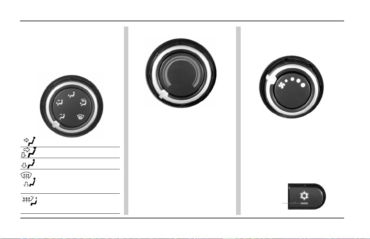
INDIGO MANZA A T A GLANCE
Heating, Ventilation & Air Conditioning
(A) Air flow Direction Control Knob:
The air flow can be changed by
turning the air direction control knob
(A) to the desired direction.
Towards face
Towards face and feet
Towards feet
Towards feet and windshield
(Recommended for clearing
mist on windshield)
Air demist/defrost windshield
(Recommended for clearing
heavy fog or snow)
(B) Temperature-Control Knob:
The air temperature in the car can
be controlled by operating the
temperature control knob (B) on the
control panel. The temperature can be
increased by rotating the knob
towards the red segment and
decreased by rotating it towards the
blue segment.
(C) Blower Speed Regulation
Knob:
The HVAC system has a four speed
blower. The blower speeds can be
regulated by operating the blower
knob (C) at the centre of the control
panel.
(D) A.C. ON/OFF Knob:
The A.C. can be switched ON by
pressing the switch (D) on the A.C.
control panel provided the blower is
ON and the engine is running. The
indicator lamp will show that the A.C.
is ON.
Indicator
66
Page 69
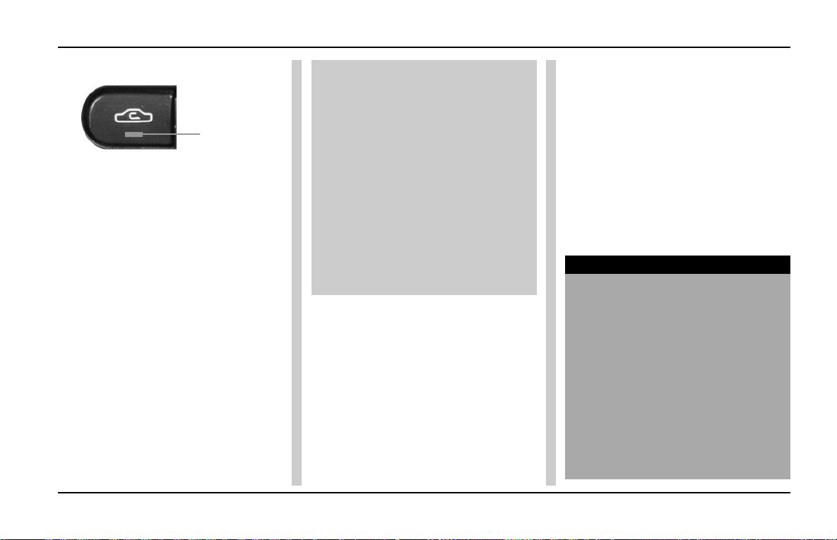
Heating, Ventilation & Air Conditioning
INDIGO MANZA A T A GLANCE
(E) Recirculation / Fresh Air Switch:
Indicator
Q If HVAC is to be put into air
recirculation mode, press switch
'E'. The indicator lamp will show
air in recirculation.
Q To put car in Fresh air mode
release switch 'E'. Indicator lamp
will be OFF .
Q In recirculation mode, air inside
the car is circulated again and
again. In Fresh air mode, air is
taken from outside and circulated
in the car.
Recirculation mode can be used
Q While driving in dusty condition
Q T o avoid traffic pollution
Q To get quick cooling/heating as
required.
Whenever discomfort is felt switch air
circulation mode to fresh.
The A.C. can be switched ON only
if the blower is ON and engine is
running. When A.C. is switched ON
engine idling RPM increases
marginally, to adjust to the A.C.
compressor load. When desired
temperature is achieved A.C. trips
OFF automatically .
The A.C. compressor get s switched
OFF automatically when engine gets
overheated. The A.C. is
automatically switched ON when the
engine gets cooled.
Normal Heating:
Knob 'A' - Towards face and feet
Knob 'B' - Suitable temperature
position
Knob 'C' - Suitable blower speed
A.C. - OFF
Air Circulation - Fresh switch
Quick Heating:
All settings as explained above except
air circulation switch to recirculation.
Once the car is heated, switch back
to fresh mode.
Normal Cooling:
Knob ‘A’ - towards face
Knob ‘B’ - Cool position.
Knob ‘C’ - desired speed position
A.C. - ON
Switch ‘E’ - suitably as explained
NOTICE
T o achieve quick cooling effect, open
the windows slightly while you operate
the air conditioner, with air circulation
switch in fresh mode, fan at 4th
speed and air direction toward
“FACE”. Side Air vents and central
Air vents to be opened completely.
Once temperature inside has come
down sufficiently , close the windows
and change air circulation suitably
to fresh/recirculation and reduce
blower speed suitably.
67
Page 70
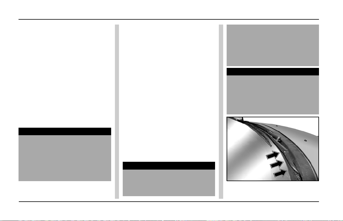
INDIGO MANZA A T A GLANCE
Heating, Ventilation & Air Conditioning and Lamps
Demisting:
In rainy season or in areas of high
humidity, mist formation inside
windshield glass is observed. T o clear
mist, dehumidified air is passed on
the windshield glass.
The position of control knobs should
be adjusted as follows:
A.C. - ON
Knob 'A' - Towards windshield (for
demisting)
Knob 'B' - at suitable temperature
Air circulation - at desired position
Knob 'C' - Desired speed position
NOTICE
• When mist is cleared, switch the
knob "A” position to Face mode.
• In high humidity areas, if cold air
continues to flow over windshield,
it may cause sudden fogging on
outside surface of windshield.
Defrosting:
In low temperature/sub-zero
temperature areas, to clear frost
formation outside the windshield
glass, this setting is used.
First start the engine and warm it by
pressing on the accelerator pedal.
Knob 'A' -T owards windshield
Knob 'B' - Maximum hot position
Knob 'C' - Very High
Switch 'E' - Fresh air mode condition,
AC - OFF
Once the windscreen has become
clear, move the fan switch to desired
speed.
A Plastic scraper can be used to clear
windshield glass, once the ice starts
melting
NOTICE
• Refrigerant charged in the air
conditioning circuit has been
identified on the label over
bonnet. Use only refrigerant as
given in the label for topping up
or re-charging.
• AC Gas charging Quantity
should be as per the above label.
NOTICE
Fresh air is taken from the grill
opening provided at base of
windshield glass outside the car.
Keep these openings clear and free
from fallen leaves etc.
68
Page 71
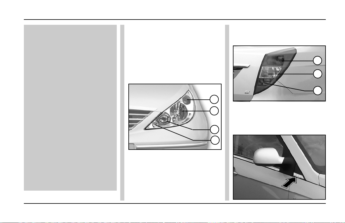
Heating, Ventilation & Air Conditioning and Lamps
INDIGO MANZA A T A GLANCE
Operating the AC after a gap of
more than a month of non use :
Start engine & let it warm up for at
least 2 min. for idling speed to drop
below 1000 rpm. Switch ON A.C.
system with following settings :
a) Blower switch:ON
b) Blower speed:High
c) Engine speed:Below 1000 rpm
d) A.C. switch : ON
A.C. should be operated for at least
5 minutes before switching it off.
Following the above procedure
once a month ensures proper
lubrication of compressor parts.
Avoid switching ON the A.C. at high
engine speed as this may damage
A.C. compressor.
Get your A.C. system serviced at
regular intervals ensures its
optimum performance and prolong
its life.
Head Lamp:
Head lamps are clear lens type having
multi focal reflector and are provided
with two H7 halogen lamps for straight
ahead illumination of the road over a
long distance or dip beam for short
distance visibility . It also contains side
indicator lamp and a parking lamp.
1
2
3
4
1. Turn Indicator
2. Head Lamp (High Beam)
3. Head Lamp (Low Beam)
4. Parking Lamp
Tail Lamp:
The tail lamp assembly incorporates
the following
1
2
3
1. Brake/Parking Lamp
2. Direction Indicator
3. Reverse Lamp
Side Repeater Lamp:
69
Page 72
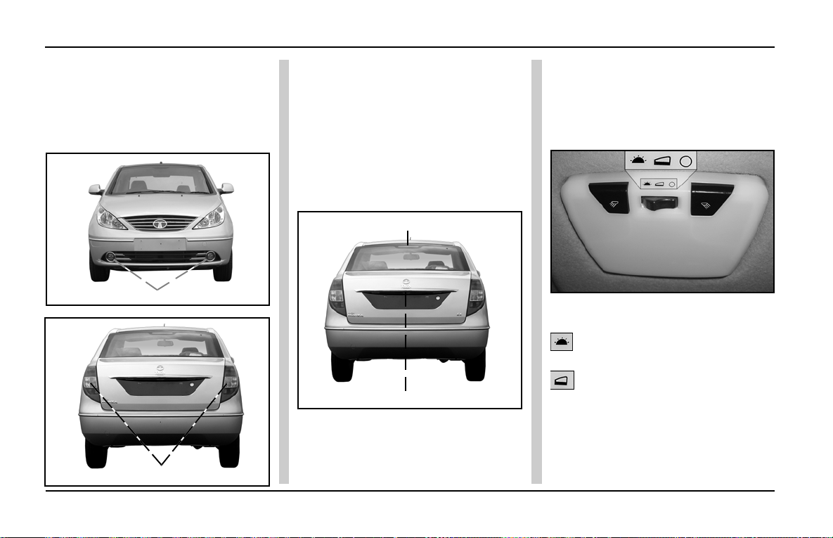
INDIGO MANZA A T A GLANCE
Lamps
Fog Lamp (if fitted):
Front and rear fog lamps are provided
for your convenience and they can be
operated via the Facia switches that
are located above the HVAC controls.
Front Fog Lamps
Rear Fog Lamps
70
High Mounted Stop Lamp:
High mounted stop lamp is provided
at the top of the rear windshield and
glows whenever brakes are applied.
Registration Plate Lamps:
Two concealed lamp s are provided for
illumination of the rear registration
number plate.
High Mounted Stop Lamp
Registration Plate Lamps
Front interior light with reading
lamps:
Interior roof lighting and reading lamps
with inbuilt switches are provided on
the roof near the rear view mirror.
The central rectangular switch has
three positions:
ON - The lamp will come ON as
long as switch is in this position.
DOOR - In this position the lamp
comes ON when any of the doors are
opened. When the door is closed, the
lamp will not go OFF immediately, but
remain ON for 5-8 sec and goes OFF with
dimming.This can also be called the
"Theatre effect".
Page 73
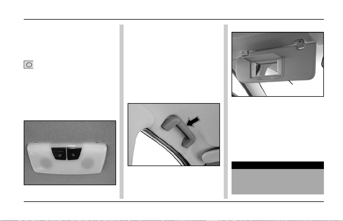
Sunvisors & Grab Handle
INDIGO MANZA A T A GLANCE
This helps the driver to settle himself
in his seat and insert the key in the
ignition switch. When the key is
turned to the ‘IGN’ position, the lamp
goes OFF immediately.
OFF - In this position the lamp
will not come ON at all. Two
rectangular shaped push type
ON / OFF switches are provided
separately for the right and left reading
lamps.
Passenger interior light with
reading lamps:
Two interior roof reading lamps with
inbuilt switches are provided on the
roof in the passenger area. T wo push
type ON / OFF switches are provided
separately for the right and left reading
lamps.
The switch has two positions:
ON - The lamp will be ON as long as
switch is in this position.
OFF - In this position the lamp will
remain OFF .
Roof Grab Handle :
These are provided on all seats except
driver seat. This helps in comfortable
positoning of passengers.
Sun visors:
Sunvisor
Two adjust able sun visors are provided
inside the cab above the windshield
to prevent sun glare. Lower the sun
visors to protect the eyes from bright
sunlight. The sun visors can also be
moved sideways towards the door.
A vanity mirror has been provided on
the back of the passenger’s sunvisor.
NOTICE
When not in use, keep the sunvisors
in their original position or else, they
may block driver’s vision.
71
Page 74
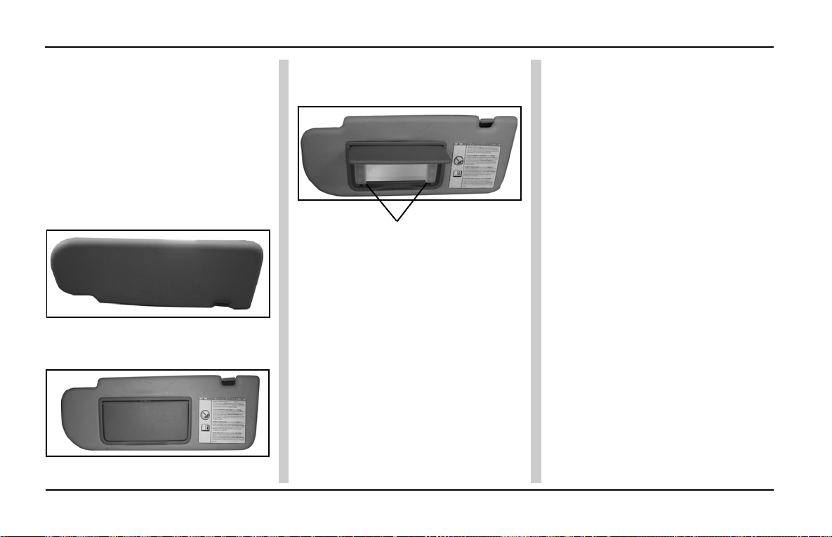
INDIGO MANZA A T A GLANCE
Sunvisors & Vanity Mirror
Vanity Light on passenger side
(if applicable):
V anity lights are provided on the sides
of the vanity mirror on passenger side
sunvisor. The lights come ON when
the vanity mirror cover is opened and
go OFF when the cover is closed.
Passenger side Sun Visor closed
Passenger side Sun Visor opened
with Vanity Mirror cover closed
Passenger side Sun Visor opened
with Vanity Mirror cover open:
Vanity Mirror Light
Passenger side sunvisor opens with
vanity mirror cover. In this condition,
lights on sides of vanity mirror come
ON. They remain ON as long as the
vanity mirror cover is open. When
the vanity mirror cover is closed, the
lights go OFF .
72
Page 75
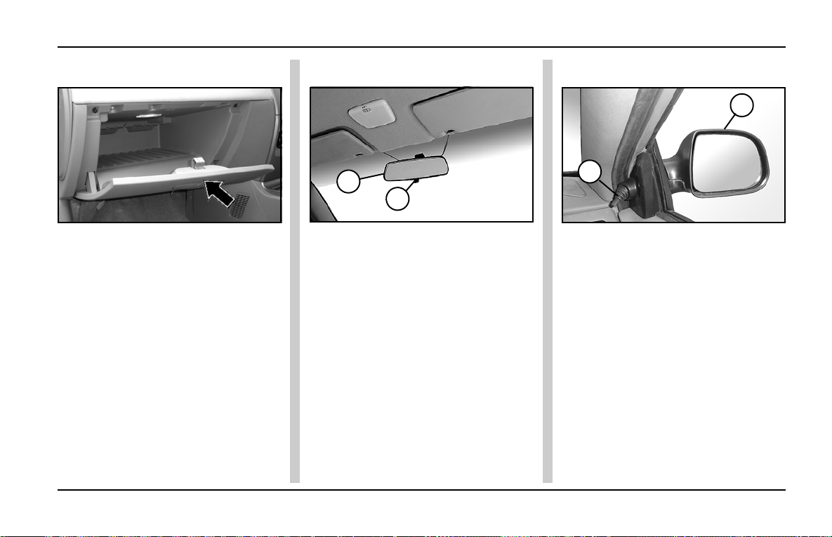
Glove Box & Rear View Mirror
INDIGO MANZA A T A GLANCE
Glove Box:
Glove Box
The glove box is located on the dash
board in front of the co-driver’s seat.
It can be locked with the ignition key .
It is also illuminated.
Inner Rear View Mirror : Outer Rear View Mirror :
1
2
2
1. Inner Rear View Mirror
2. Antiglare Position Lever
An antiglare mirror is fitted inside the
car. Provision has been made for two
positions:
- Normal position
- Antiglare position
1. Outer Rear View Mirror
2. Lever for adjustment
The outer rear view mirror is fitted on
the door from outside and can be
adjusted by the lever provided inside
the door. In some versions the mirrors
are provided on both the doors.
Use antiglare position only when
necessary, as it reduces rear view
clarity.
1
73
Page 76
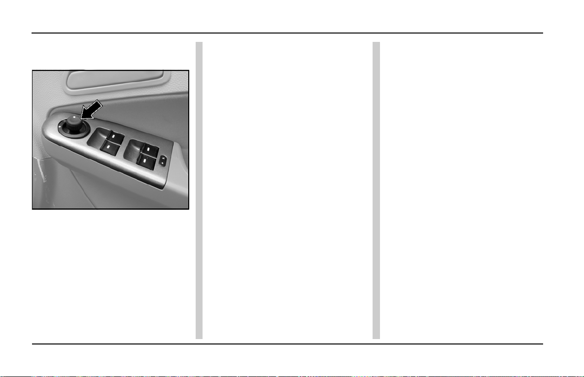
INDIGO MANZA A T A GLANCE
Motorised Outer Rear View Mirrors
Motorised Outer Rear View Mirrors:
(if fitted)
Operating knob - Motorised Outer Rear
View Mirror
Your car is equipped with motorised
outer rear view mirrors fitted on both
front doors and can be adjusted to the
desired position with the help of a
switch / knob mounted on the driver’s
side along with the window winding
switches.
Using this switch / knob, the driver can
adjust the car’s outer rear view mirrors
without lowering the glasses and
shifting from his / her position.
Steps to operate the Rear View
Mirrors :
1. Move the main switch to the left
“dot ” to adjust the left side rear
view mirror and to the right “dot ”
to adjust the right side rear view
mirror.
2. Use the 4 positions of the knob
(marked by a triangle) to adjust the
rear view mirrors to correct angles.
74
Page 77
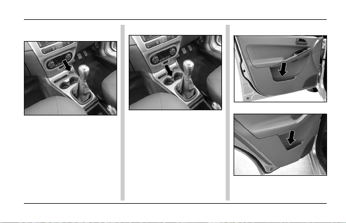
Power Socket, Cup Holder & Utility Pocket
INDIGO MANZA A T A GLANCE
FLOOR CONSOLE :
A) Power Socket :
Power Socket for front passengers
A power socket is provided on floor
console at the front.
Power socket can be used to tab 12V
supply (10A Max.) for operating
external gadgets.
B) Cup holder :
Cup holder
Two cup holders are provided for your
convenience in the centre console
ahead of the gear shift lever .
C) Utility pocket / box :
Front utility pocket / box
Rear utility pocket / box
Utility pocket is provided on all the
doors to keep magazines / books etc.
75
Page 78
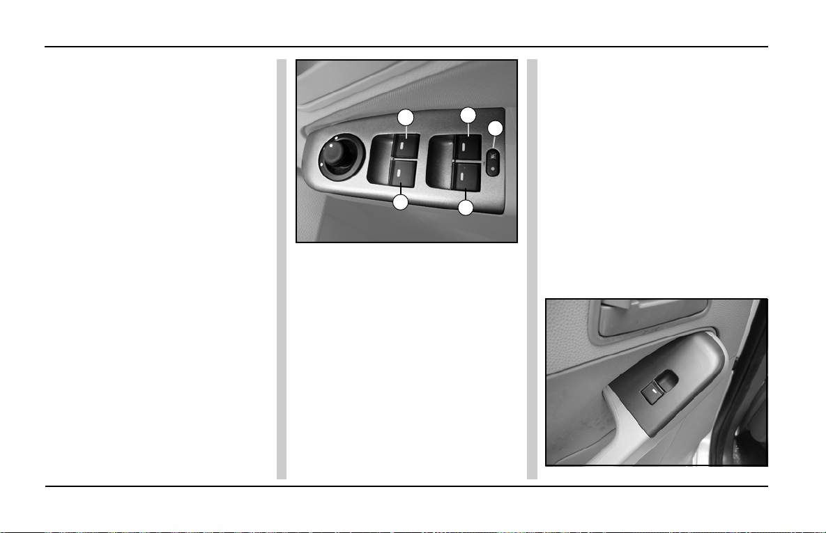
INDIGO MANZA A T A GLANCE
Power Windows
Power Windows :
Glasses on all four windows of the car
can be operated by switches provided
on the main control panel located on
the driver’s arm rest. They work only
when the key is in the IGN position.
Glasses are wound up by pulling the
switch and are lowered by pressing it
down.
A safety locking arrangement has also
been provided and can be activated by
a push type switch located at the
centre, below the window switches. It
has two positions:
LOCK – When switch is pressed and
red light comes ON.
UNLOCK – When switch is released
When the switch is in LOCK position,
the rear window switches (located on
rear doors) do not function. The rear
window glasses can still be operated
by using the switches on the driver’s
arm rest. Illumination on the rear
window switch goes off when the
2
3
Window winding switch on driver’s door
1. Lock / Unlock Button
2. Front Right Window Winding Switch
3. Front Left Window Winding Switch
4. Rear Right Window Winding Switch
5. Rear Left Window Winding Switch
4
1
5
switch is in locked condition. Press
down the lock button to unlock.
Individual window winding switches
have been provided on co-driver’s door
also.
Express Down - This facility is
provided for the driver’s door only. This
function allows you to roll down the
driver's window glass faster by pressing
the respective switch a little longer.
Note - This function is cancelled if the
up or down switch is pressed
anywhere during the Express Down
operation.
WARNING
Power window switch (On Rear
Doors): Individual window winding
switches have been provided on the
rear doors.
Window winding switch on Rear Door
76
Page 79
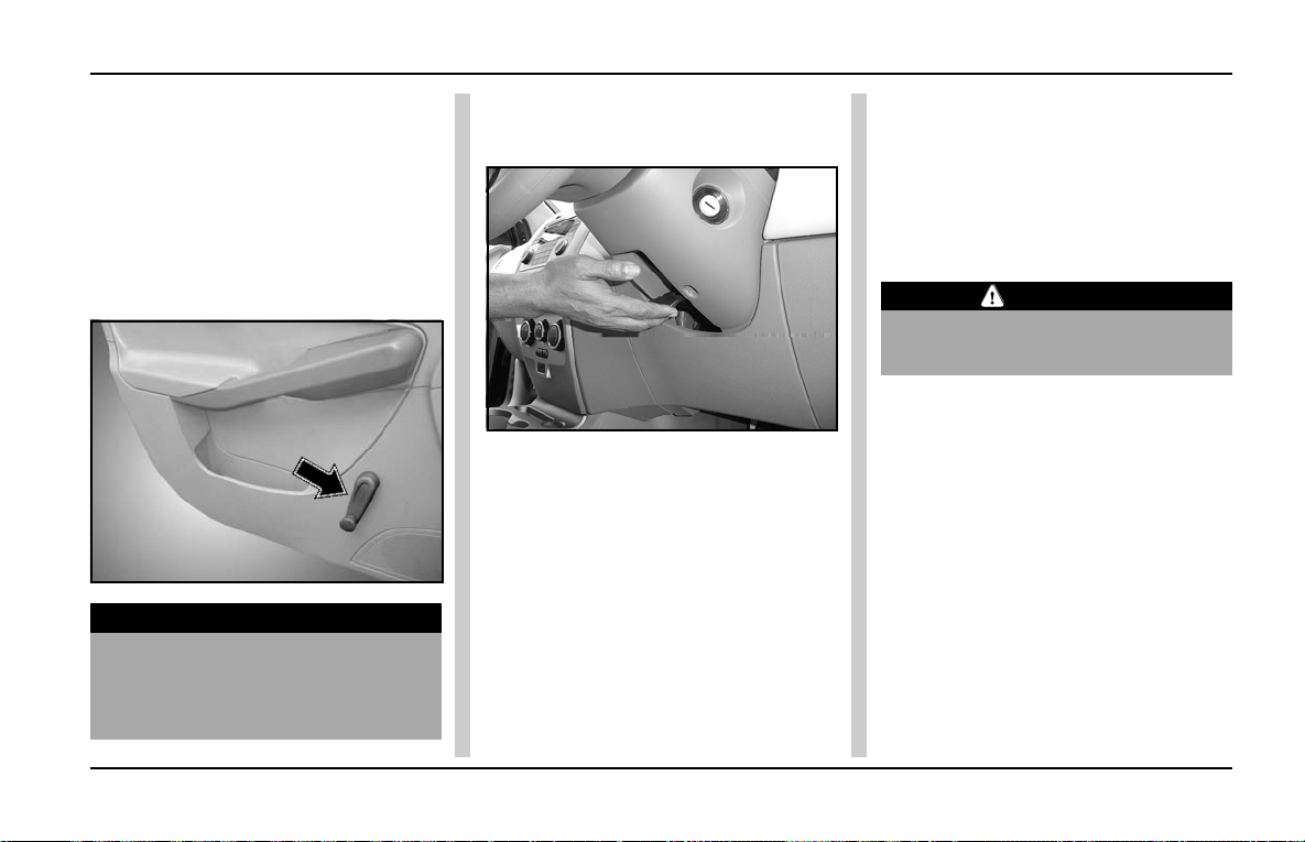
Window Winding & steering Wheel Position Adjustment
INDIGO MANZA A T A GLANCE
To close the door window glass, pull
the knob up and to open, push the
knob down.
Manual Window Winding :
In some versions, power windows are
not provided. In such cars, use winder
handle manually for lowering or raising
up window glasses manually .
WARNING
While raising the glass, take care
to avoid fingers / hands getting
trapped between glass and the
frame.
Steering Wheel Position
Adjustment:
Steering Adjustment Lever
You can adjust the steering wheel
position to suit your convenience.
Adjust the steering wheel position as
follows before you start driving.
1. Adjust the seat to a comfortable
position.
2. T o adjust steering wheel position,
push down the tilt lever as shown
in figure to unlock steering column.
3. Move the steering wheel up or
down to the desired position.
4. Lock tilt lever by pulling it up to
the lock position. Make sure that
steering wheel is securely locked
by checking up and down direction.
CAUTION
CAUTION
Steering wheel should be adjusted
only when the car is stationary .
77
Page 80
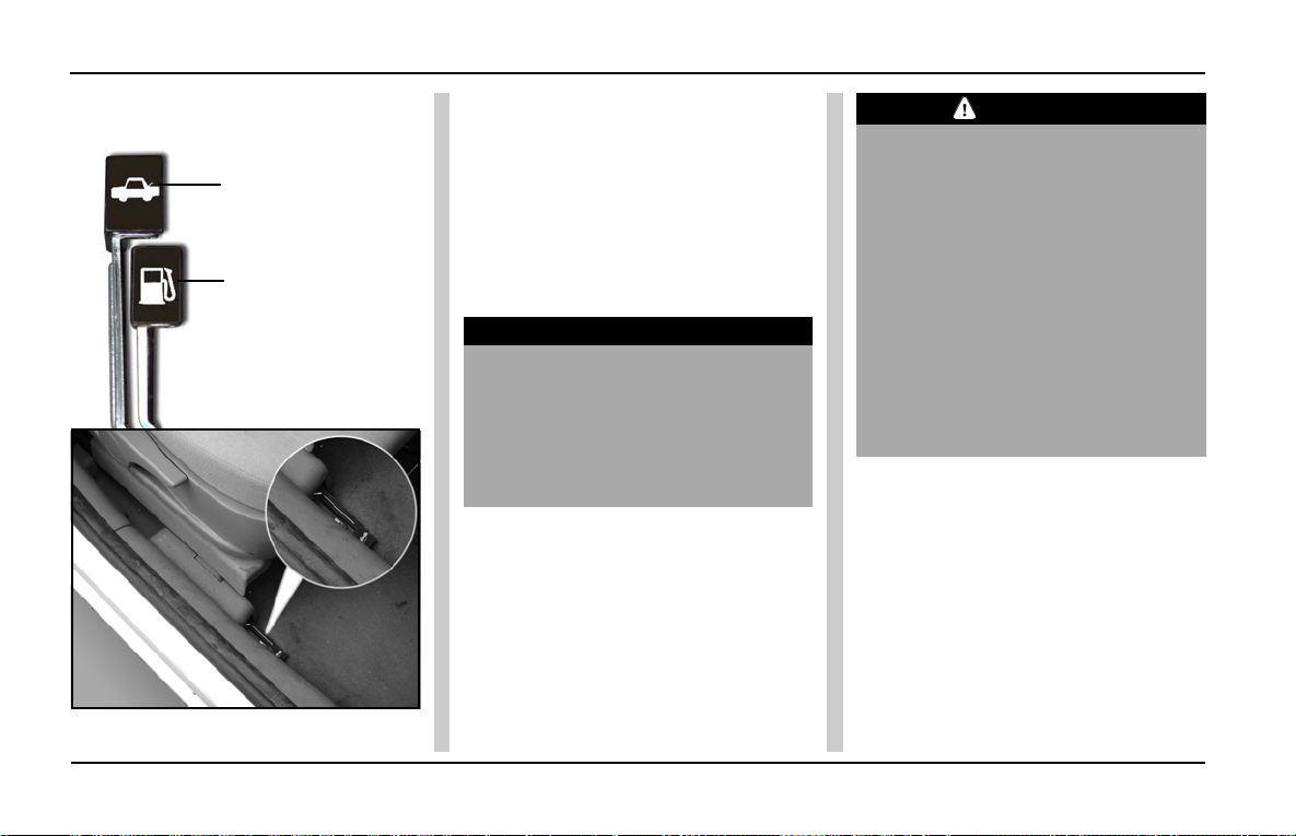
INDIGO MANZA A T A GLANCE
Fuel Flap & Boot Opening / Closing
Fuel Tank flap and Boot Opening:
Boot opening
Lever
Fuel tank flap
opening Lever
Fuel Flap / Tail Gate Opening Lever
The fuel flap is located on the left rear
side of the car. The fuel flap can be
opened by pulling the opening lever
located at the right hand side of the
driver’s side. located at the right hand
side of the driver’s side on the floor
For closing, simply push the fuel flap
till it gets locked.
WARNING
Fuel vapour is extremely hazardous.
Always stop the engine before
refueling and never refill near sparks
or open flames. Please do not use
your cell phones when you are at a
petrol station.
CAUTION
CAUTION
• Remove the fuel filler cap slowly,
and wait for any hissing to stop.
If the cap is opened suddenly , the
fuel may be under pressure and
may spray out, causing injury.
• Always use only original
specification fuel cap or an
approved equivalent available at
Authorised Dealers. A wrong cap
can result in serious
malfunctioning of the fuel system
and the emission control system.
Boot opening :
T o open the boot, pull the lever “Boot
opening Lever” located at the right
hand side of the driver’s side.
It can also be opened by using door
key. The lock is located on the tail
gate.
For closing, simply push the boot
downwards till it gets locked.
78
Page 81
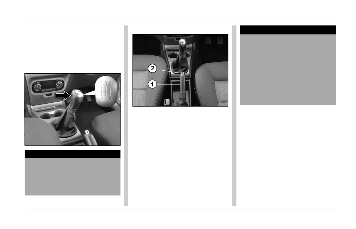
Gear Shifting Lever & Parking Brake
INDIGO MANZA A T A GLANCE
Gearshift lever and shifting
pattern:
The gearshift lever is mounted on the
center console between the two front
seats. The gearshift pattern is as
shown on the gear lever knob.
NOTICE
The reverse gear should be engaged
only when the car is stationary.
Wait for five seconds after
declutching to ensure smooth
engagement of the reverse gear.
Parking brake :
1. Parking Brake Lever
2. Release Button
A mechanical parking brake acting
only on the rear wheels is provided on
your car. The parking brake lever is
located behind the gearshift lever . T o
apply the parking brake, pull the lever
up fully. The indicator lights on the
instrument panel. To release it, pull
the lever up slightly , press the release
button and push the lever down. The
parking brake indicator on the
instrument panel will go OFF when the
parking brake lever is fully released.
NOTICE
• Apply the parking brake properly
before leaving the car and
release it before moving.
• When parking on a steep slope,
do not rely on the hand brake
alone to hold the car. Engage the
car in low forward gear when
facing uphill and reverse gear
when facing downhill.
79
Page 82

INDIGO MANZA A T A GLANCE
Anti-Theft Device- Immobiliser
Immobilizer system:
Immobilizer system is designed to
prevent car theft by electronically
disabling the engine starting system.
The engine can be started only with
car’s original Immobilizer ignition key
which has an electronic identification
programmed code.
Immobilizer system consists of
following components,
1. Immobilizer unit (ICU) – A add-on
part on the ignition switch fitted on
steering column.
2. Two Electronic keys (E-key) - To
start the car.
CAUTION
1. E-key of other cars will not start
the engine.
2. Customer should,
a. Use only one E-key .
b. The other E-key should be
kept at safe location.
c. Note “key Tag no.”
information (and keep it safe)
which is required while
getting new/spare keys.
Please note that It is not
possible to prepare new/
spare keys without “key Tag
no.”
d. Take precaution about
E-keys, as without it car
cannot be started.
80
Page 83

Anti-Theft Device- Immobiliser
Immobilizer system :
The behavior of Immobilizer and car under “Ignition OFF and ON” conditions, is explained in table below with immobilizer
status lamp (“lock” symbol on the instrument cluster)
CAR STATUS LAMP CAR STATE MEANING/ FUNCTION OF THE ST ATE
CONDITION
Ignition OFF Blinking Locked Car Immobilized and Awaiting Electronic key
Ignition ON OFF Unlocked Normal Condition Ready to start the car
ON Locked - Problem with key ( Wrong E-key used to start car)
- Problem with Immobilizer system contact Tata
dealer to inspect the system
INDIGO MANZA A T A GLANCE
81
Page 84
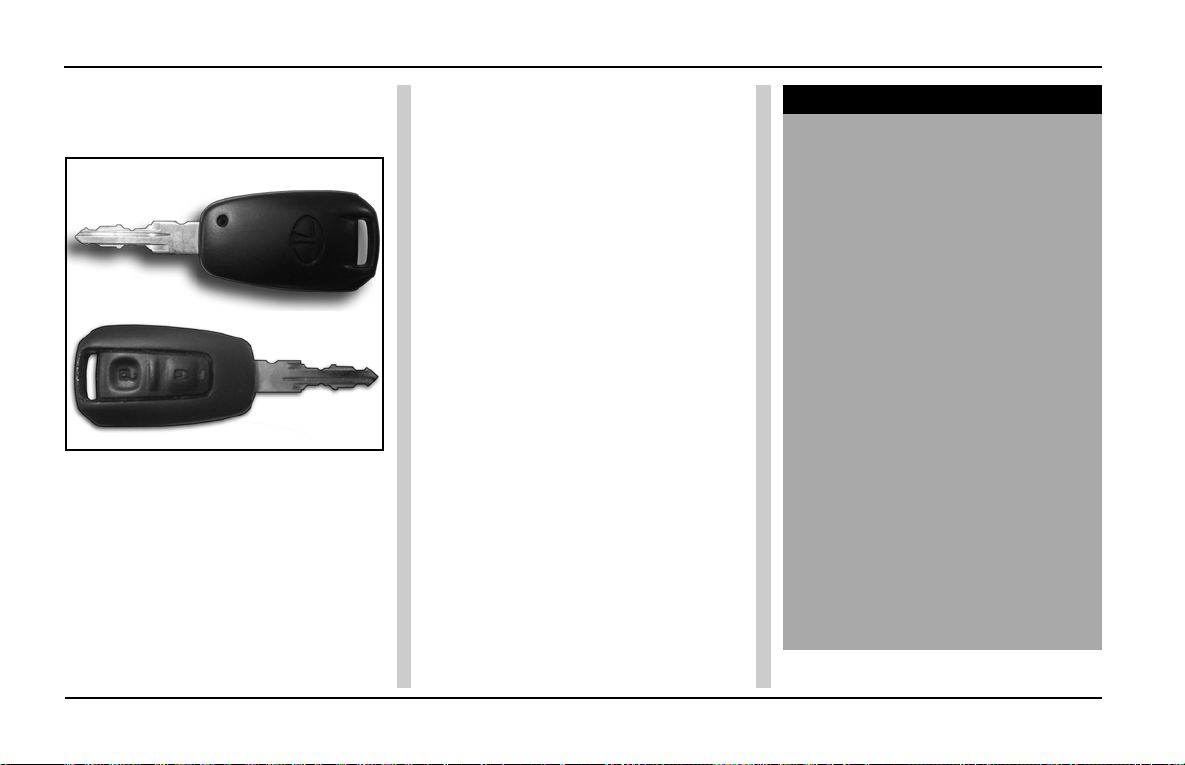
INDIGO MANZA A T A GLANCE
Anti-Theft / Keyless Entry System
Central Locking System:
E-Keys :
Unlocking Principle :
The E-keys are learned for a specific
immobilizer and are unique to the car.
The transponder inbuilt into the
ignition E-key carries a unique
identification code. The Engine
management system (EMS) and
Immobilizer has common secret
code. Both these codes are used
while unlocking the car.
When key is inserted and the ignition
is switched ON, all the codes are
communicated within concerned
components (E-key, Immobilizer and
EMS). The engine starts only if all
codes match. In case of a mismatch
of the codes, system prevents the
engine from starting.
Loss of E- Keys :
If any one of the E-key is lost,
contact TATA dealer as soon as
possible to have the lost key
deactivated and to have the new
E-key.Please note that Second
original E-key is required for making
additional E-keys.
If both the E-keys are lost, contact
the authorised TAT A dealer.
NOTICE
Do’s and Don’ts of immobilizer
system
• Do not turn ON ignition switch
by using electronic key with any
type of metal wound around its
grip or in contact with it. This
may be detected as abnormal
condition by immobilizer and
prevent engine from starting.
• Do not leave electronic key in
areas of high temperature. The
transponder in E-Key will
behave abnormally when
reused.
• Do not try to start the car when
the Immobiliser indicator lamp on
the instrument cluster is glowing.
In this condition the car will not
start and the car’s battery will
also be drained due to frequent
cranking.
82
Page 85
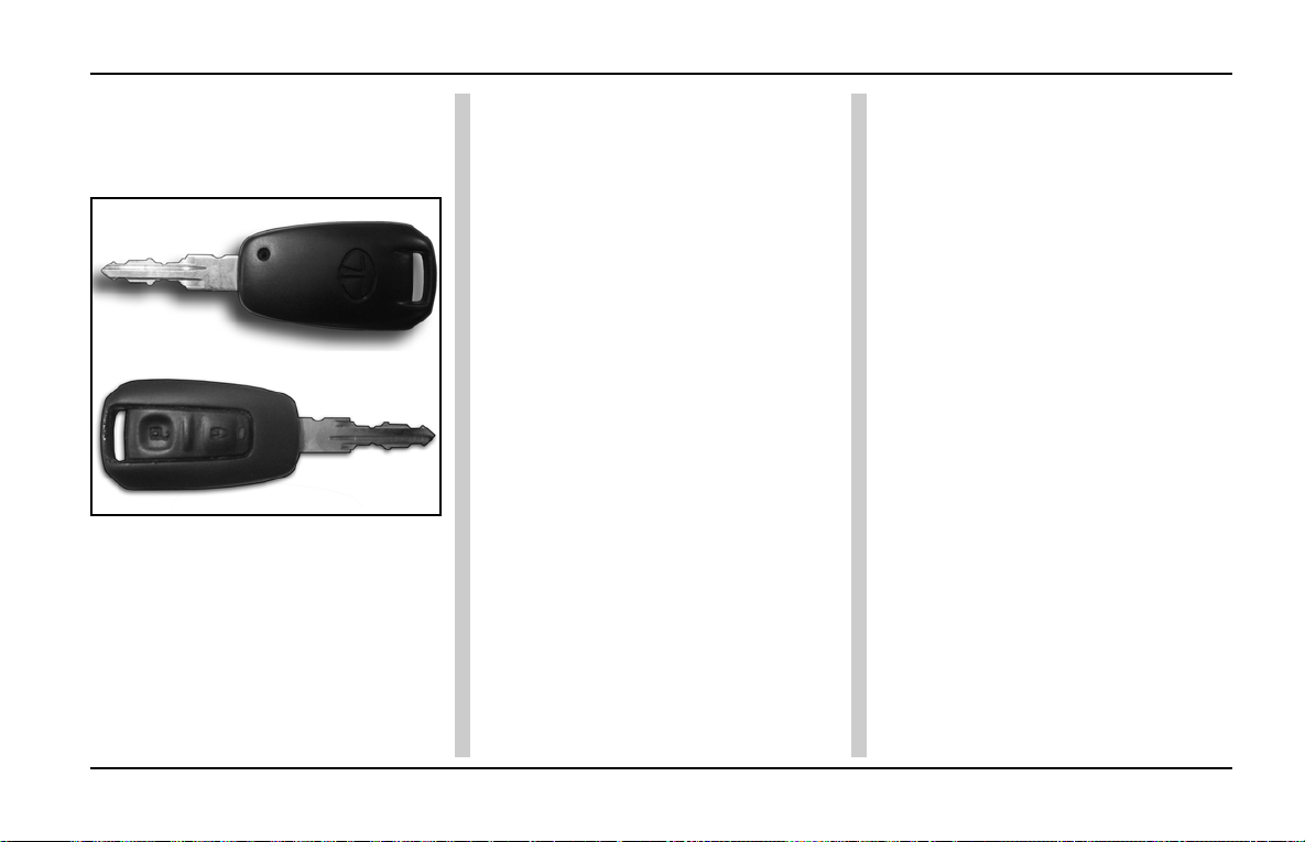
Anti-Theft / Keyless Entry System
INDIGO MANZA A T A GLANCE
Central Locking System:
ANTI THEFT / KEYLESS ENTRY
SYSTEM (RKE) :
This is an Anti-Theft security system,
which has a Remote Keyless
operation for door lock / unlock.
The system consists of following:
1. Key with integrated switches for
Lock / Unlock
2. Body control module
Features:
Q Locking / Unlocking the vehicle
from distant place.
Q Finding the vehicle (Refer Car
Seek)
Q Manual Central door Locking /
Unlocking (Ref. centridoor locking
feature)
Q Auto lock and unlock optional
feature on some vehicle to Lock /
Unlock
Car Seek:
Used to find the vehicle.
Press ‘LOCK’ on User Remote when
the vehicle is locked (Range 7.5
meters max)
Gives three flashes on turn
indicators.
Central Door Locking Feature:
All door can be locked / unlocked by
manually locking / unlocking the driver’s
door (using mechanical key / knob)
Learning Process:
Steps:
1. The driver’s door should be
unlocked.
2. Insert the key in the car’s ignition
switch.
3. Turn the ignition ON-OFF,
ON-OFF four times quickly
(in 6 seconds). T wo flashes by the
external indicator lamps will be
given after this step (Note: If you
try starting the car during the
learning process, the process will
be cancelled).
4. After the two flashes, quickly
press the LOCK and UNLOCK
button on the remote
simultaneously (within 10
seconds). By doing so, the
Remote will learn with your car’s
BCM.
83
Page 86
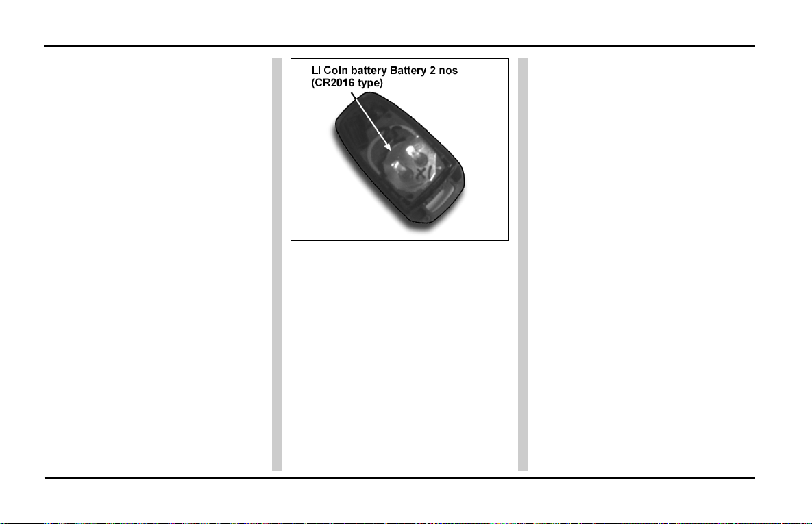
INDIGO MANZA A T A GLANCE
5. T wo flashes by the indicator lamp s
will be given after this step also.
At the same time, the doors will
LOCK and UNLOCK.
This is a confirmation the Remote
has been learn.
6. If you wish to learn the next
Remote (duplicate key) at the
same time, repeat steps 4 and 5
within 10 seconds.
Anti-Theft / Keyless Entry System
7. The remote key learning will end
with a single long flash if the
ignition is switched ON as soon as
the above process is complete.
8. To learn the next remote after
completing one remote learning
cycle, repeat all above steps.
84
Remote Key Af ter Opening up of back
screw
Low Battery V oltage st atus can be
observed by User:
a) Considerable reduction in the
range of Remote
b) LED on the Remote start to blink
at faster rate when a button is
pressed.
Page 87
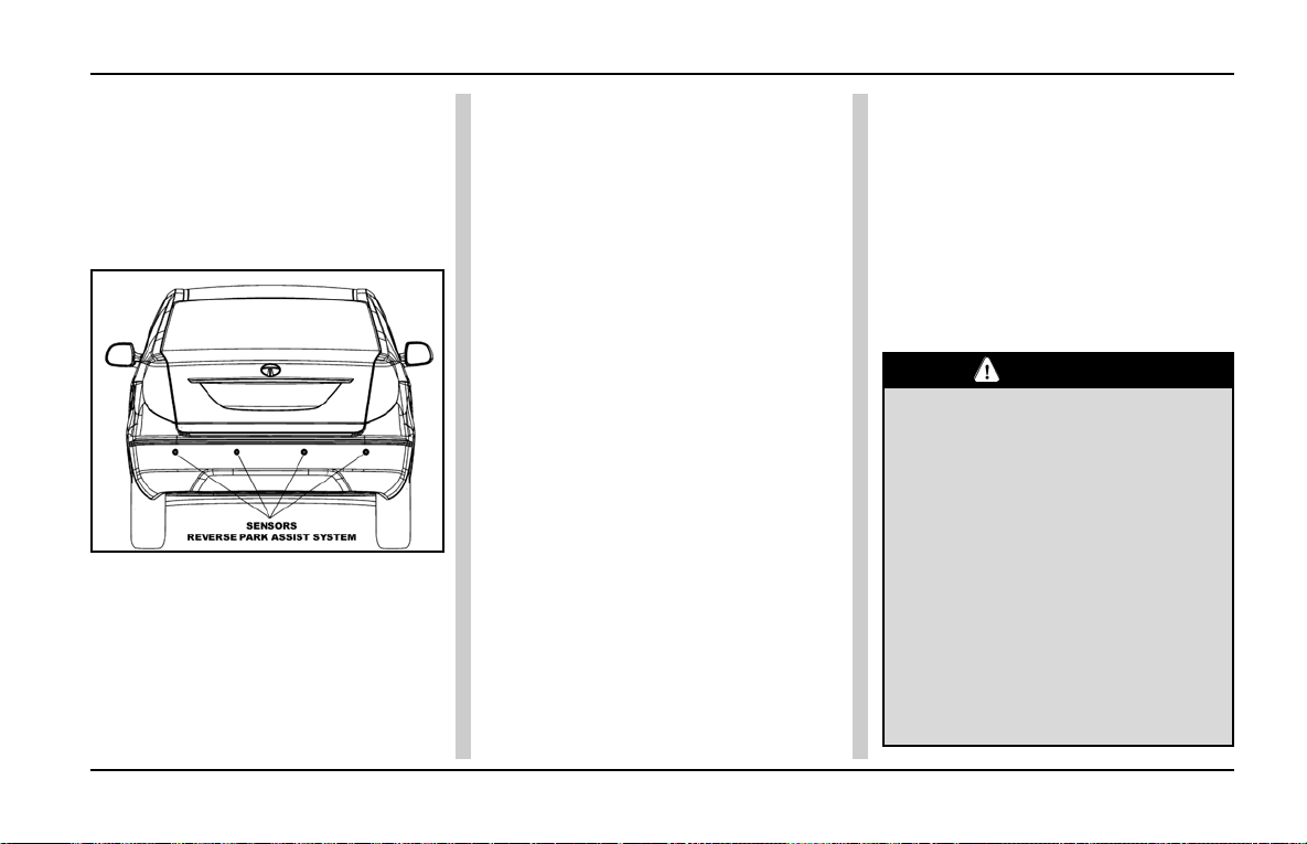
Reverse Park Assist System (RPAS)- If fitted
INDIGO MANZA A T A GLANCE
REVERSE PARK ASSIST SYSTEM
(RPAS) WITH AUDIO : (IF FITTED)
An ultrasonic sensor based reverse
guiding system is equipped on your
vehicle to aid safe driving while reversing the vehicle.
The system alerts you of obstacles
while reversing the vehicle at low
speed. This system consists of four
reverse park assist ultrasonic
sensors, a controller & a buzzer. The
RPAS system gives only an audible
signal, when the rear bumper of your
vehicle comes closer to an object. The
buzzer operates with different an
audible signals as per the distance
between rear bumper and obstacles
to alert the driver.
The system is automatically activated
when the reverse gear is engaged.
Operating Instructions:
Switch ‘ON’ the ignition. On engaging
the reverse gear, the RPAS system
will get activated automatically. When
the obstacle enters the sensing zone,
the system starts giving an audio
indication (initially for 0.8 second).
The buzzer beep frequency and buzzer
sound time duration depends on the
obstacle distance as given below:
Zone 1 : This zone is nearest to the
rear bumper (up to 50cm). Sensors
detect obstacles and give an audio signal (Continuous beep).
Zone 2 : This zone is the middle zone
(up to 80 cm). Sensors detect
obstacles and give an audio signal
(Fast beep).
Zone 3 : This is the most distant zone
(up to 120 cm). Sensors detect
obstacles and give an audio signal
(Slow beep).
Stop the vehicle immediately once the
continuous beep starts as the vehicle
is very close to the obstacle.
CAUTION
1. The RPAS system performance
is dependent on the reflection of
ultrasonic waves from the
obstacle.
2. System cannot sense the
following;
a) Wire mesh, hand rail, small
objects & some obstacles which
are well above and well below the
bumper level.
b) Ostacles like cotton, wool,
foam, textiles or spongy surfaces
85
Page 88

INDIGO MANZA A T A GLANCE
Reverse Park Assist System (RPAS)
which will absorb ultrasonic
waves easily .
c) Pot holes, trenches or
drainages which are below the
ground level.
3. System may give wrong signal
on reversing in the following
situations:
a) When the vehicle on
grasslands & bumpy roads.
b) While vehicle is moving from
plain ground to slope like backing up downhill or vice versa.
c) When the bumper is tilted more
than the normal position or when
the vehicle is heavily overloaded.
d) When the temperature of the
obstacle is high as hot surfaces
reflect fewer sound waves than
cold surfaces.
e) If there is an excessive
increase in humidity as it increases the sound speed
(max.by 2%) as compared to dry
air.
f) When the vehicle is equipped
with high power radio antenna on
rear side.
g) If sensor is at extreme temperatures: below -30° Celsius or
above 80° Celsius.
4. System may give false alarm
during heavy rain conditions,
during snow conditions or heavy
wind conditions.
WARNING
1. This system is strictly a driver
assistance device. It is not a substitute for the driver’s responsibility while driving. Under no circumstances will the manufacturer accept any responsibility or
can be held liable for any direct
or indirect, incidental or consequential damage caused by negligent use of this system.
2. Clean the sensors properly and
keep them free from ice, dust,
mud, water, chewing gum etc. for
proper working of the system.
3. Please practice reverse parking
using different obstacles to grasp
the system performance.
4. Pressing the sensor on active region may damage the sensors &
may hamper its sensing range
causing the system to malfunction.
5. Always STOP your vehicle when
a continuous beep is heard, as it
indicates an object at dangerous
distance not more than 1 meter
from the rear bumper.
6. Never use high pressure water to
clean the sensors and also never
use hammer on it.
7. Never fit any “buzzers” which are
locally available in the market for
Reverse parking.
86
Page 89

GETTING STARTED
Q Door- Locking / Unlocking
Q Child Lock
Q Tail Gate - Locking / Unlocking
Q Front Seat
Q Front Seat Adjustments
Q Head Restraints
Q Utility Tray
Q Rear Seat
Q Rear View Mirrors
Q Rear Seat Adjustment
Q Seat Belts
87
Page 90
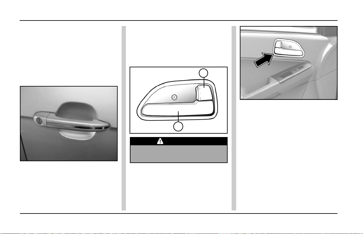
GETTING STARTED
Door Lock
Front Doors (Driver and Co-driver)
Locking / unlocking doors with key
from outside:
Both front doors (drivers and co-driver)
have separate locking facility. Front
doors can be locked or unlocked from
outside using the E-key .
Insert the E-key and turn it anticlockwise to open or clockwise to lock
the door. Pull the Door handle to open
an unlocked door.
Locking without a key from inside:
All the doors can also be locked or
unlocked independently from inside
by pressing or pulling the knob (1).
Press to lock and Pull to unlock.
1
2
CAUTION
When locking doors this way , do not
leave the key inside the car.
Opening the doors from inside:
All doors can be opened from inside.
To open, pull the door opening lever
(2). Location of door opening / locking
lever.
88
Page 91
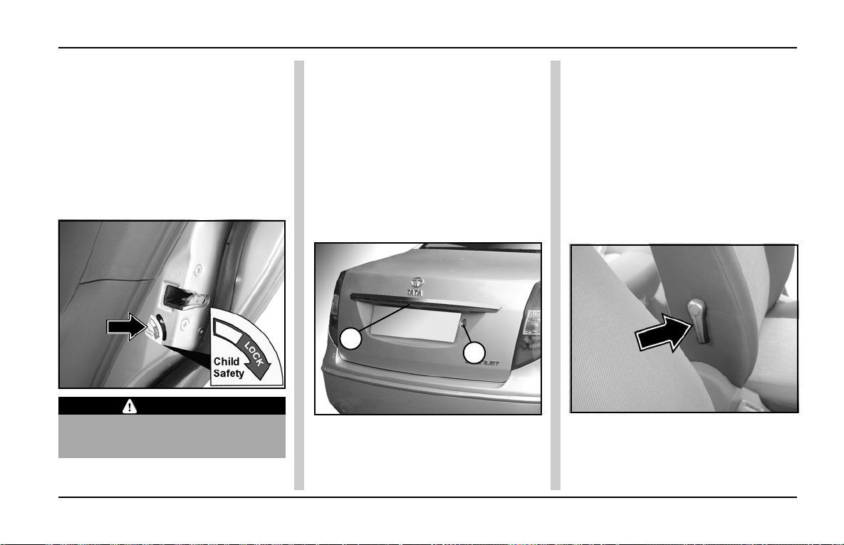
Child Lock, Tail Gate & Front Seat
GETTING STARTED
Childproof lock:
Both the rear doors of the car are
provided with a child proof lock. Push
the lock lever located on vertical face
of the door near the lock downward
before closing the door. The door which
has been locked by activating the child
lock cannot be opened from inside, it
can be opened only from the outside.
CAUTION
Deactivate the childproof lock when
not required.
Boot Locking / Unlocking:
Insert the key and turn it anti-clockwise
to open or clockwise to lock the boot.
Pull the door handle to open the boot.
The boot is automatically locked once
it is shut. The boot can also be opened
by a lever located near the fuel flap
opening lever. This is located on the
right hand side of the driver’s side on
the floor.
1
2
1. Boot Handle 2. Boot Lock
Front Seats :
Bucket type seats are provided with
multiple adjustments.
Lumbar Support :
Lumbar support is provided on Driver
and Co-driver’s seats to give you
driving comfort. It is adjusted by the
lever (1) provided on the side of the
seat backrest.
Lumbar Support
89
Page 92
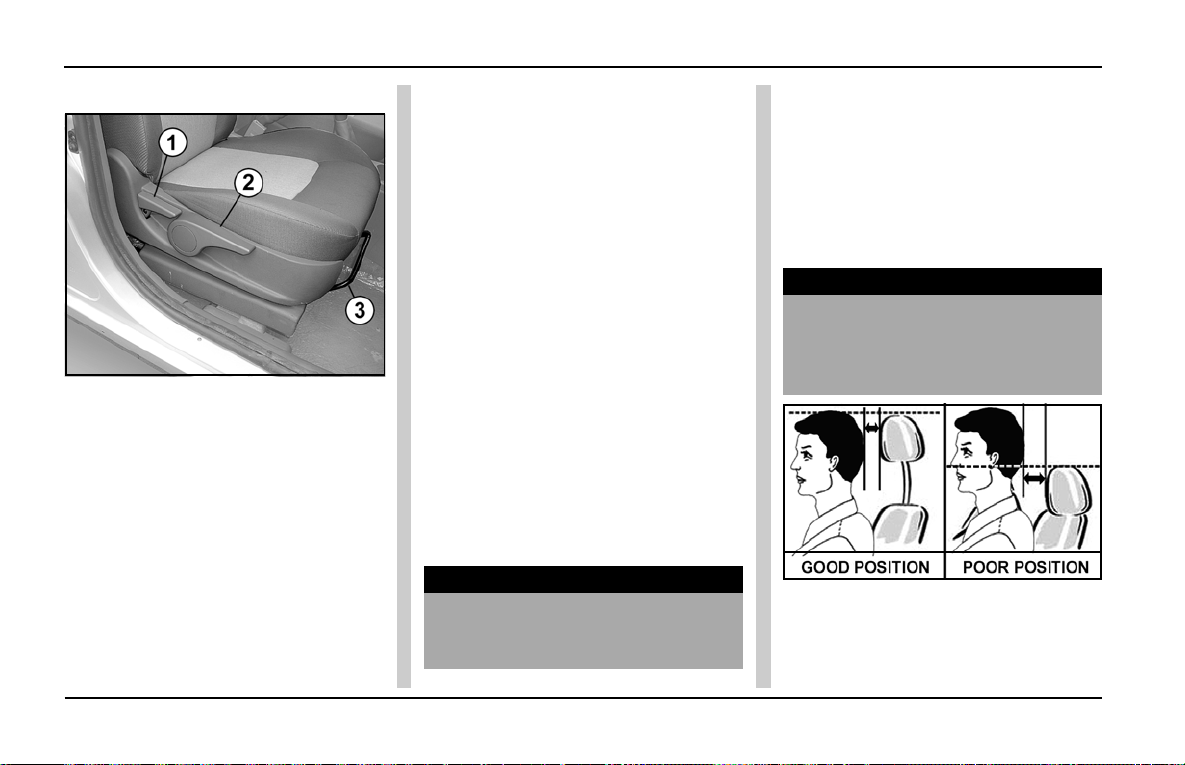
GETTING STARTED
Seat Adjustment
Front Seat Adjustments:
1. Seat Back Recliner Lever
2. Height Adjustment Lever
3. Lever for Forward and Backward
movement
1. Seat Back Recliner:
To change the seat back angle, lean
forward slightly and raise the smaller
lever. Lean back to the position you
want and release it. Make sure that
lever returns to it’s original position.
2. Height Adjustment (Only for
Driver’s Seat):
Driver’s seat height can be adjusted
by a big lever located on the seat base
on the right hand side, just ahead of
the seat back adjustment lever. You
can raise the seat height by pumping
/ pulling the lever upwards until
approriate seat height is reached and
lower it by pumping / pushing the lever
downwards.
3. Moving the Seat Forward and
Backward:
T o adjust the seat position, lift the lever
under the seat cushion front, slide the
seat to the desired position and
release the lever. Once the desired
position is achieved, release the lever
to lock the seat. Make sure the seat
is locked firmly in position.
WARNING
Do not adjust the seat when driving.
Adjust the seat only when the car
is stationary.
Head restraint :
Adjustable head restraints are provided
for bucket seats in front. To increase
their height, lift up and leave at desired
click position. To reduce the height,
press the unlock button and push the
head restraint down wards.
WARNING
Avoid driving the car with the headrestraint removed as it is a safety
item. Do not attempt to adjust the
head-restraint while driving the car.
90
Page 93
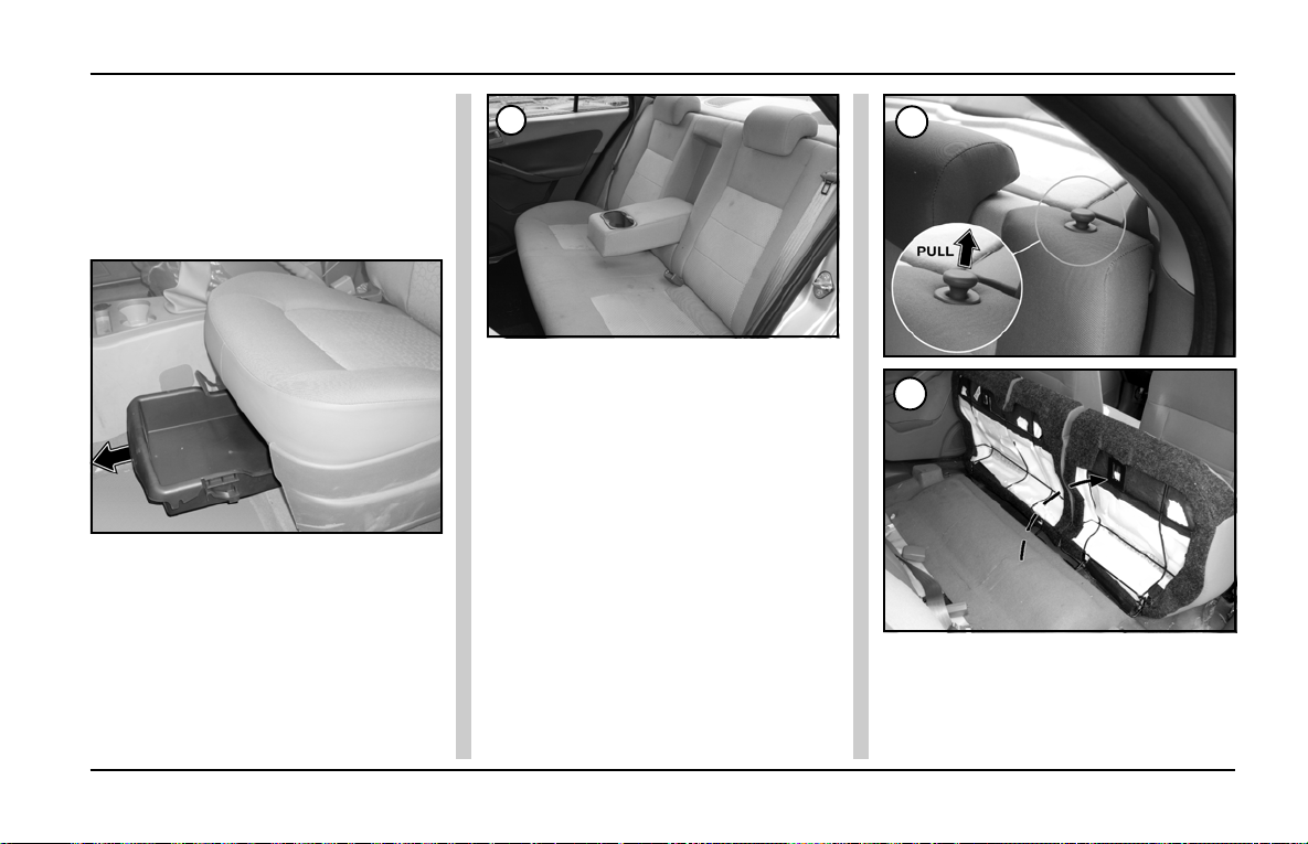
Seat Adjustment
GETTING STARTED
Utility Tray (Co-driver Seat):
A Sliding tray is provided below codriver’s seat. Important papers/
documents can be kept here.
To open the tray, lift the tray and pull
out.Push for closing back the tray.
Utility Tray
Foldable Armrest:
A foldable arm rest has been provided
in the rear seat. This can be used by
the occupants for resting their hands.
It also has two cup holders. When not
required, this armrest can be folded
back into the seat.
1
Rear Seat Adjustments :
Rear seat is in two parts i.e. 60 / 40
split. T wo built-in head restraints are
provided on the rear seat.
These head restraints have to be
lowered (if raised) before folding the
seat.These seats can be
independently folded as and when
required or for carrying extra luggage.
Steps to fold the rear seat (if
applicable):
1. Lift the seat base from the back and
place it vertically (Fig.2).
2. To fold the seat back-rest, pull the
2
3
knobs near the headrest. (Fig.3)
3. The seat back-rest folds down to
create a completely flat luggage
area.
91
Page 94
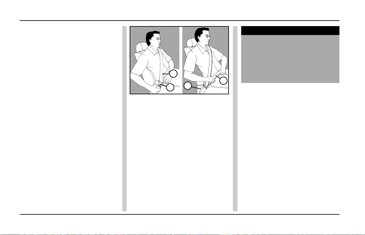
GETTING STARTED
Seat Belts
Seat Belts
Occupants safety is of utmost
importance. Y our car is equipped with
seat belts, both front and rear as a
part of occupant restraint system.
Why Seat Belts
Wearing seat belts properly can
protect you from being thrown against
the insides of the car or against other
occupants in case of an accident or
sudden braking. It will reduce the
chances of severe injury .
How to use seat belts
This car has three point inertia reel
type front and rear seat belts in the
out board positions and a lap belt for
middle passenger on rear seat. In
normal driving, the belt lets you move
freely in your seat. In case of an
accident or sudden braking, inertia
reel automatically tightens the belt to
help restrain your body.
1
3
2
1. Seat Belt 3. Lock Buckle
2. T ongue 4. Lap Belt
4
The anchor end of the shoulder belt
is adjustable to suit the height of the
passenger wearing it. The lap belt has
one manually adjusted belt that fits
across the hip bone.
Make sure that your seat is adjusted
to a good driving position and the back
of the seat is upright.
1. Pull the tongue across your body
and insert it into the buckle.
2. Check and ensure that the belt is
not twisted.
WARNING
Twisted seat belt s can cause injury
in a collision as the full width of the
belt isn’t available to absorb the
impact. This puts more force on the
bones beneath the belt, leading to
injury. Don’t wear twisted seat belt s.
3. Position the lap portion of the belt
as low as possible across your hip
bone.
4. Pull up the shoulder part of the belt
to remove the slack. Make sure that
the belt goes over your collar bones
and across chest.
5. To unlatch the belt, press the red
button on the buckle. Guide the
belt to the pillar as it retracts.
92
Page 95

Seat Belts
GETTING STARTED
WARNING
Improper positioning of the belt on
shoulder is dangerous. An
improperly positioned belt will
provide little or no protection in a
collision. Always make sure the
seat belt is positioned across your
shoulder and near your neck, but
never under your arm. on your neck,
or on your upper arm.
6. The belts are meant (intended) for
adult occupants only.
7. Each belt should be used by one
occupant only. The belt must not
be put round a child, seated on
passengers lap.
8. When the belt has been in use in
a serious accident or shows signs
of severe fraying / damage or of
having been cut, replace with an
approved belt kit.
9. The belt must not be altered or
modified during use.
WARNING
Using one seat belt for more than
one person at a time is dangerous.
A seat belt used in this way cannot
spread the impact forces properly
and the two passengers could be
crushed together and seriously
injured. Never use one belt for more
than one person at a time.
10.The belts if required should be
replaced, by Authorised personnel
only .
11.The belt should not be
disassembled. If required,
authorised personnel only should
carry out disassembly and
assembly.
12.Clean the webbing with a mild soap
solution recommended for upholstery .
Bleachi n g or dyei ng the webbing
may weaken it.
Lap belt
Pull the tongue to the desired length.
Insert it into the buckle until you hear
a click.
Adjust the belt length. T o lengthen the
belt, hoId the tongue at a right angle
to the webbing and pull. To shorten,
pull the loose end of the webbing.
T o unfasten, depress the button in the
buckle.
WARNING
Positioning the lap portion of the
Seat Belt too high can be
dangerous as in a collision, this
would concentrate the impact
force directly on the abdominal
area, causing serious injury . Wear
the lap portion of the belt snugly
and as low as possible.
93
Page 96
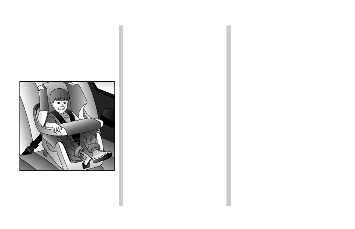
GETTING STARTED
Seat Belts
TATA MOTORS strongly urges that
the driver and passengers in the car
be properly restrained at all times with
seat-belts. Failure to do so could
increase the chance of injury and /
or the severity of injury in accidents.
Baby or Small Child:
Use a child restraint system
appropriate for the child until he / she
is old enough to wear the car’s seat
belt properly . If the child is too big for
a child restraint system, he / she
should be seated on the car’s back
seat
restrained using the car’s seat-
belt.
Use the seat-belt when the child is in
the rear seat also. According to
accident statistics, a child is safer
when properly restrained in the rear
seat than in the front seat.
For Airbag Equipped Cars:
• Rear Seat is the SAFEST for
children.
• Never put rearward facing child
restraints on front seat unless the
passenger airbag is deactivated.
This is very important and if not
followed, it can lead to a serious
injury or even death.
• Do not use a forward facing child
restraint system in the front seat
of the car, unless the passenger
airbag is deactivated.
General Guidelines:
• Children below 12 years are
always safe in child restraints.
• Refer child restraint
manufacturer’s instructions for
installation.
• Select the child restraint based on
the weight of the child. Age should
be used as a reference.
• Rearward facing child restraints
are preferred for children with
weight less than 9kg or until they
can sit themselves without any aid.
94
Page 97
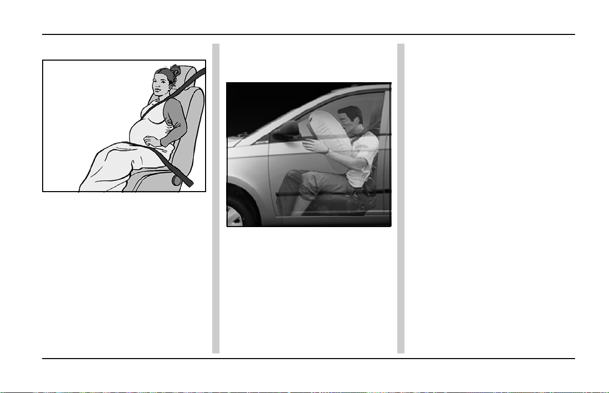
Air Bag
GETTING STARTED
Expectant Mothers: Driver Air Bag and Passenger Air
Bag: (Supplementary Restraint
Systems-If Applicable)
TATA MOTORS recommends the use
of a seat-belt. Kindly consult your
doctor for specific recommendation.
The lap belt should be worn securely
and as low as possible over the hips
and the waist.
Injured person :
T AT A MOTORS recommends the use
of a seat-belt for injured person.
Depending on the injury, consult your
doctor for specific recommendations.
Your vehicle is fitted with an air bag
for the driver, located in the steering
wheel, and a passenger air bag is
located above the glove box
compartment. Vehicles fitted with an
air bags can be identified by the “AIR
BAG” label on the steering wheel.
The air bag is supplementary restraint
system. It is designed to be used in
addition to seat belts to help protect
against head and chest injuries in
certain moderate and severe frontal
and front angular collisions.
The air bag system is not visible until
it is activated. Because the system
senses crash severity, some frontal/
angular collisions will not inflate the
Air bags. Airbags are not designed to
inflate in rollover, rear side or slow
speed frontal/ angular crashes
because the necessary protection can
be achieved by the seat belt alone.
Operation :
Sensors in the ECU detect the degree
of severity of frontal/ angular impact.
The air bag(s) are designed to deploy
if the collision suits the criteria for
deployment.
• The sensor switches close the
circuit and nitrogen gas is
produced that fills the air bag by
burning the propellant.
95
Page 98
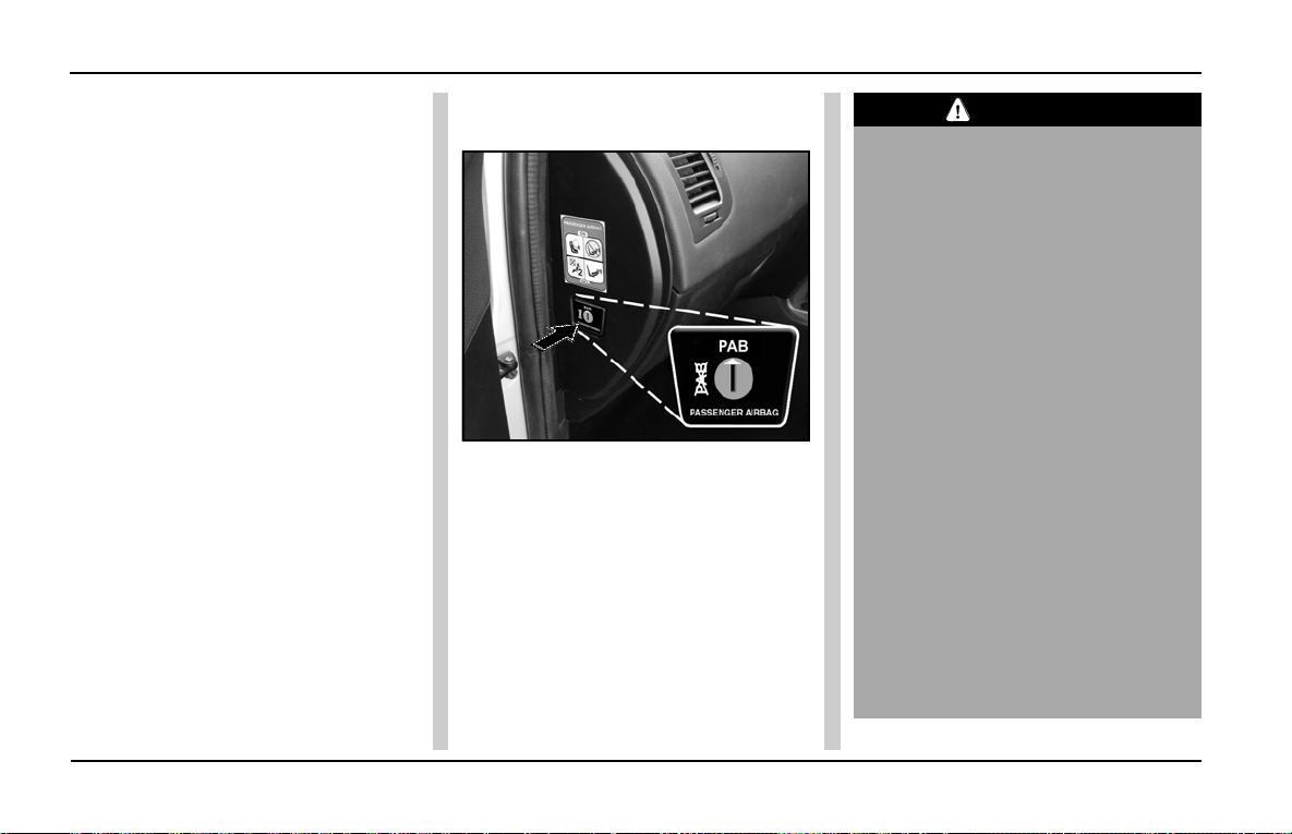
GETTING STARTED
Air Bag
• The inflating air bag deploys out
of the steering wheel in the front
of the driver and passenger air bag
of the dash board in front of the
passenger . This action takes place
in a fraction of second.
• The bag(s) deflate as the gas
escapes through the vents.
• Airbag(s) may only deploy with the
ignition switch in ON position. The
system will however work for about
30 seconds immediately after
switching OFF of ignition. Y ou may
hear a noise along with some
smoke, dust and smell of burnt
propellant immediately after the air
bag has inflated. DO NOT P ANIC
as this is normal.
• Passenger Air Bag (PAB) switch
provided on the left side of the
dashboard should always be
ACTIVE. If in case the front
passenger seat is unoccupied, the
PAB may be prevented from
deploying by turning the PAB
switch to INACTIVE by using the
ignition key .
CAUTION
• Air bag systems components get
hot after inflation, Do not touch
after inflation.
• For persons suffering from
breathing problems or asthma, get
out of the car promptly for some
fresh air as the smoke may cause
breathing problems.
• Always turn the PAB switch to
“P AB” in case the front passenger
seat is occupied.
• Always wear seat belts. The
wearing of seat belts is required
even when the air bag is fitted. Air
bags do not replace the seat belts.
• Do not allow a front seat
passenger to obstruct the
operation of the passenger airbag
by placing feet, knees of any
other part of the person, or any
other objects in contact with, or
in close proximity to, an air bag
module.
96
Page 99

Air bag
GETTING STARTED
• Always wear your car's seat belts
correctly as they can prevent you
from accidental injury when the air
bags inflate. In addition, both driver
and front seat passenger (If a
passenger air bag is fitted), should
adjust their seats to provide
maximum practical distance from
the air bag.
• An air bag, when it inflates may
cause injury . Minimise the risk of
injury by ensuring that front seat
occupants are wearing their seat
belts and are seated correctly,
with the seat as far back as is
practical.
• DO NOT service, repair, replace,
modify or tamper with part of the
air bag SRS, or wiring in the
vicinity of an air bag SRS
component; this could cause the
system to activate, resulting in
personal injury.
The importance of wearing seat
belts :
• It will help to keep you in the proper
position when the air bag inflates.
• Reduce the risk of harm in rollover,
side or rear impact collisions.
• Reduce the risk of harm in frontal/
angular collisions that are not
enough to activate the air bag.
• Reduce the risk of being thrown
from your vehicle in a collision.
The importance of being properly
seated:
T o protect occupants in a collision, the
air bag inflates at a rate that is faster
than you can blink your eye.
• If you are too close to an inflating
air bag, it could seriously injure
you, Move your seat as far back
as practical to allow room for air
bag inflation. Never install any
rearward facing child seat
restraint in the front seat when
the passenger air bag is active,
as serious injury or death may
result from the force of the
inflating front passenger air
bag. The rear seat is the safest
place for children.
• Never place any object in front of
you while you are seated in the
front seat as it may result an injury
from the object when it is forced
towards you by the inflating air bag.
Do not cover the steering wheel or
instrument panel with an object
which may prevent the proper
deployment of the air bag.
• Where a passenger air bag is fitted,
front passenger should never sit on
the edge of the seat, stand near
the glove box compartment, rest
feet or other parts of the body on
the dash board or lean over near
the glove compartment when the
vehicle is moving.
97
Page 100
GETTING STARTED
Air Bag
Air Bag Warning Light:
The diagnostic system continually
monitors the readiness of the SRS
AIR BAG while the vehicle is being
driven. The air bag warning light on
the instrument panel will illuminate
for approximately 5 seconds when
the ignition is switched on. This is
normal and indicates the system is
performing a self check. The
following components are monitored
by the indicator :
• Airbag control module - ECU
• Driver airbag
• Passenger air bag
• Retractor Pretensioners.
• All related wiring.
If the warning light does not illuminate
when ignition is switched on, or
remains illuminated after the initial
check period & during driving, or
flashes, a fault may exists with air bag
& seat belt pre-tensioner and it should
be checked by an authorized dealer
immediately.
Air bag maintenance & servicing :
If any of the following occur, see your
Authorised dealer without any delay
for corrective action.
• The air bag warning light does not
operate briefly when the ignition
key is turned on.
• The air bag warning light illuminates
while driving.
Though your car's air bag system
does not require regular maintenance,
you should always check when a
warning about malfunction is flashed
on the instrument cluster. If this is not
attended to, the air bag system may
malfunction in the event of a collision.
Conversely , it may deploy even if there
is no collision.
NOTICE
• Any maintenance performed on
or near the components of the
SRS must be performed only by
an authorized dealer. Do not
permit anyone else to do service,
inspection, maintenance or repair
on any SRS components or
wiring.
• Similarly, no part of the SRS
system should ever be handled
or disposed of by anyone except
an authorized dealer. Improper
work on the SRS system will
result in inadvertent deployment
of the air bag or could render the
SRS system inoperative. This
could also lead to personal injury .
• Do not modify your steering wheel
or any other SRS components,
For example replacement of
steering wheel or modifications to
the steering column, front
bumper, body or frame structure
can adversely affect the SRS
performance and lead to possible
injury.
• If your vehicle has received any
front end damage, you should
have the SRS system inspected
by an authorized dealer to ensure
it is in proper working order.
98
 Loading...