

Page 1
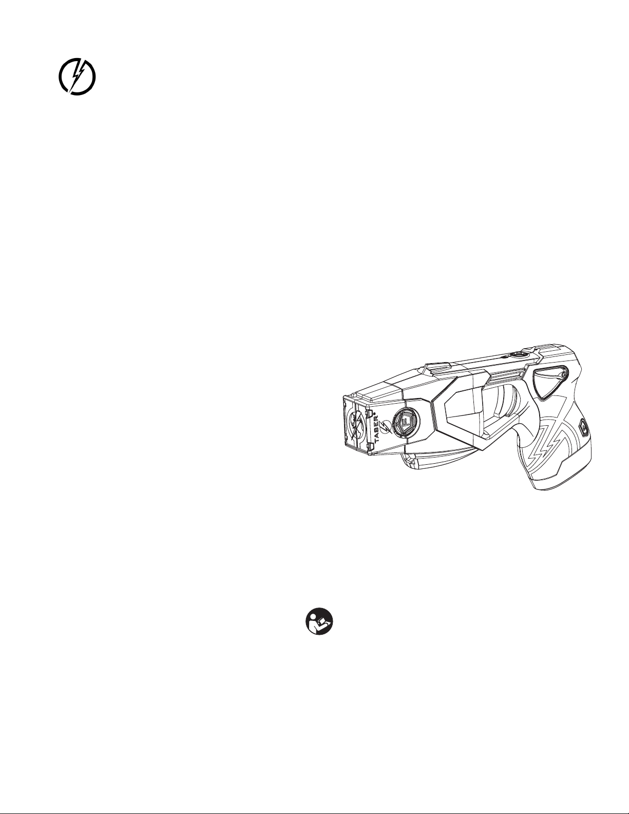
TASER X26P CEW
User Manual
Models 11000, 11001, 11002, 11003
IMPORTANT SAFETY INSTRUCTIONS
Read all warnings and instructions. Save these instructions.
The most up-to-date warnings and instructions are available at
www.axon.com
MMU0042 Rev: F
Page 2

Contents
1 Chapter 1: Warnings
1 Important Safety and Health Information
2 LASER Information
3 Firmware Update
4 Chapter 2: General Information
4 What Is the TASER X26P CEW?
4 Neuro Muscular Incapacitation (NMI)
5 Basic X26P CEW Electrical Theory
6 Chapter 3: Features
6 X26P CEW Features
6 Safety Switch
7 LASER
7 Mechanical Sights
7 Performance Power Magazine (PPM) Battery Pack
7 Changing the Battery Pack
8 Tactical Performance Power Magazine (TPPM) Battery Pack
9 eXtended Performance Power Magazine (XPPM) Battery Pack
9 Automatic Shut-Down Performance Power Magazine (APPM) Battery Pack
9 Replacing the APPM with a Dierent Battery Pack
9 eXtended Automatic Shut-Down Performance Power Magazine (XAPPM) Battery Pack
10 Signal Performance Power Magazine (SPPM) Battery Pack
10 Automatic Shut-Down Option
10 Continued SPPM Transmission in Safe Mode
11 Updating the SPPM Firmware
11 Advanced Central Information Display (CID)
11 System Status Icons
i
Page 3

12 Battery Level Icons
13 Spark Duration
13 Sample CID Displays
14 LED Flashlight
14 Selector Switch (LASER and LED Flashlights)
15 Trigger Switch
16 Chapter 4: Cartridges & CEW Operation
16 Removing the Shipping Cover from the Cartridge
16 15, 21, LS, and XP25 TASER Cartridges
17 AFID
17 Load the TASER Cartridge
17 Loading
18 Unloading
18 “Silence Is Golden”
TASER X26P CEW User Manual
19 Potential Causes of Reduced or No Eectiveness
19 Electrodes
19 Drive-Stun Backup
20 Recommended Drive-Stun Areas for Maximum Eect
21 Chapter 5: Maintenance/Troubleshooting
21 Function Test
22 What to Do Following CEW Use
22 Considerations for Handling Used Probes
22 Eects on Animals
23 Police/Military K-9 Caution
23 Uploading Firmware Revisions
23 Dataport Download Kit
23 USB Connection Status
23 Evidence Sync Oine Software
23 Trilogy Log
24 Event Log
24 Pulse Log
24 Engineering Log
24 Time Synchronization
25 X26P CEW Maintenance and Care
25 Dropped or Wet X26P CEW
Contents
ii
Page 4

26 Online Troubleshooting Guide
26 Product Returns
27 Chapter 6: Optional Accessories
27 Evidence.com Services
27 Evidence Sync Oine Software
27 TASER CAM HD Recorder
28 Holsters
29 Chapter 7: Additional Items
29 Additional Information
29 TASER Training Academy
30 Medical Research
30 Radio Waves
31 Declaration of Conformity
TASER X26P CEW User Manual
Contents
iii
Page 5
Chapter 1: Warnings
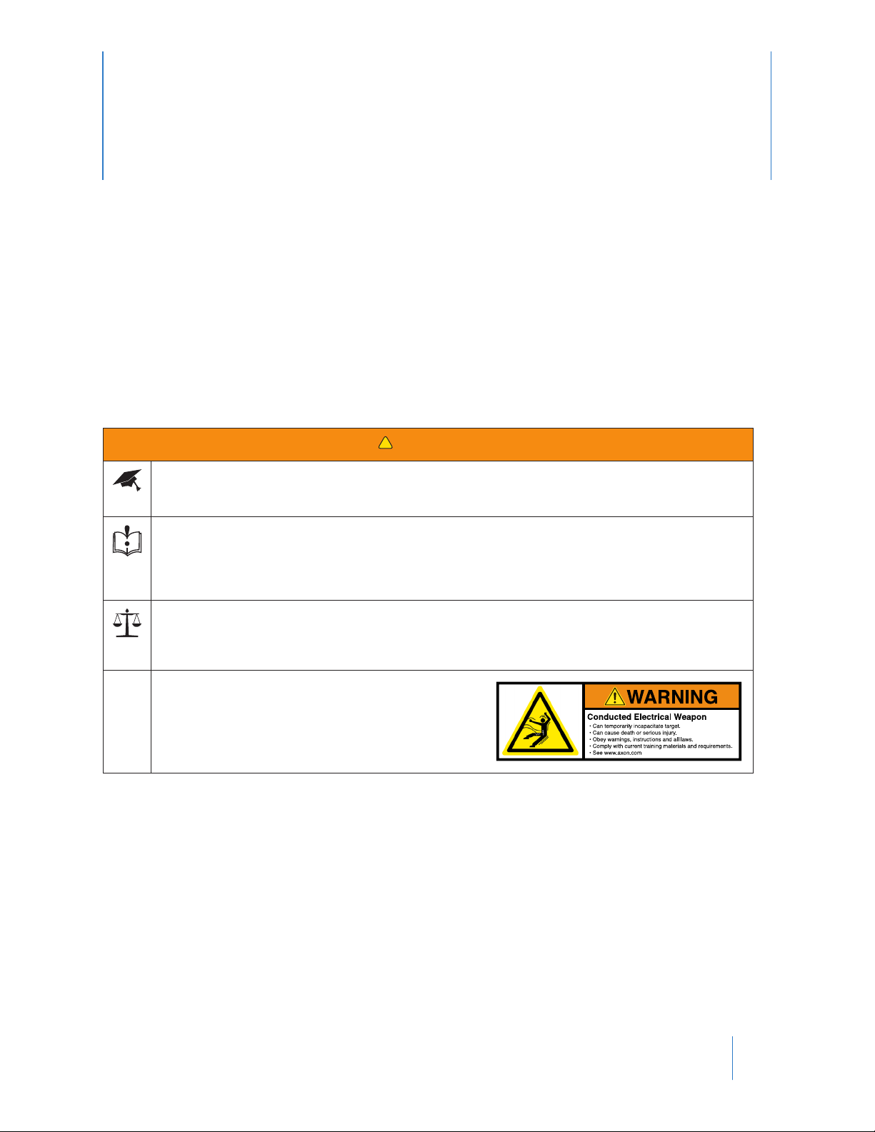
Important Safety and Health Information
Read, understand and follow the most current product warnings, safety instructions, and training materials. All
product warnings are not included in this Manual. A Product Warnings document is included with this conducted
electrical weapon (CEW) and the most current warnings are posted on our website at www.axon.com. The most
current training materials are available by contacting Axon’s Training Department. Do not attempt to use this CEW
until you have completed training with a Axon Enterprise, Inc. (Axon) Certied TASER Instructor.
!
WARNING!
Complete Training First
Signicant dierences exist between each of the TASER CEW models. Do not use or attempt to use any CEW
model unless you have been trained and certied by a Certied TASER Instructor on that particular model.
Read and Obey
Read, study, understand, and follow all instructions, warnings, information, training bulletins and relevant
TASER training materials before using the TASER X26P CEW. Failure to comply with the product instructions,
warnings, information, training bulletins, and TASER training materials could result in death or serious injury
to the user, force recipient, and others.
Obey Applicable Laws
Use of CEWs must be legally justied and comply with applicable federal, state, and local laws and regulations.
The decision to use a CEW in a particular manner or circumstance must follow applicable law enforcement
agency Guidance.
TASER CEWs are designed in probe-deployment mode to temporarily incapacitate a person from a safer distance
while reducing the likelihood of serious injuries or death. When used as directed, TASER CEWs have been found
to be safer and more eective than other traditional use-of-force tools and techniques. However, it is important
to remember that the use of force and physical incapacitation, by their very nature, involve risk that someone will
get hurt or may even die from factors that include, but are not limited to: physical resistance, exertion, individual
susceptibilities, and/or unforeseen circumstances. Any use of force or physical exertion involves risks that a person
may get hurt or die.
1
Page 6
TASER X26P CEW User Manual
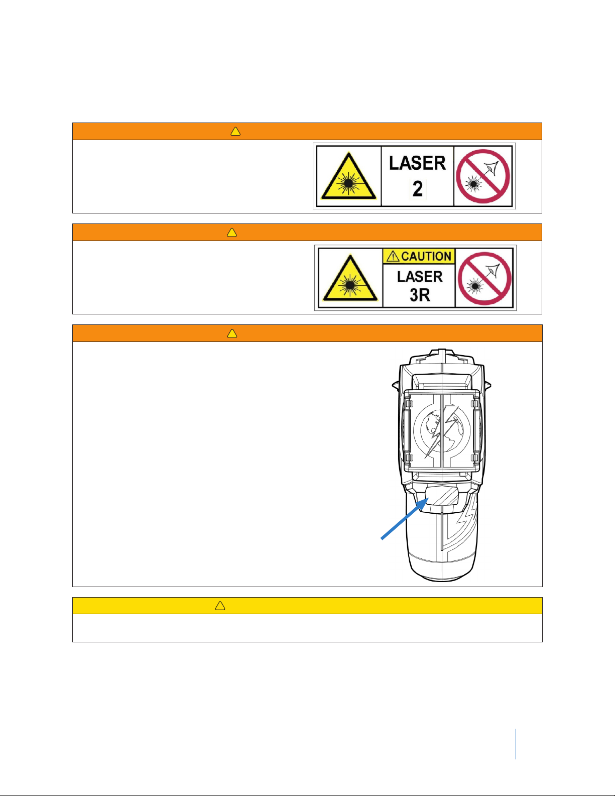
LASER Information
The CEW uses a Class 2 or Class 3R LASER as an aiming aid. LASERs can cause serious eye injury, including permanent vision loss.
!
WARNING! CLASS 2 LASER
LASER RADIATION
DO NOT STARE INTO BEAM
CLASS 2 LASER PRODUCT
!
WARNING! CLASS 3R LASER
LASER RADIATION
AVOID DIRECT EYE EXPOSURE
CLASS 3R LASER PRODUCT
!
WARNING! CLASS 3R LASER
AVOID EXPOSURE – LASER RADIATION IS EMITTED
FROM THIS APERTURE
!
CAUTION! RADIATION EXPOSURE
Use of controls or adjustments or performance of procedures other than those specied herein may result in
hazardous radiation exposure.
Use of Force Policy
Each agency is responsible for creating its own use-of-force policy and determining how TASER CEWs t its useof-force matrix based on legal and community standards. Make sure your agency has a use-of-force policy that
addresses TASER CEW use and that this policy is clearly addressed during end-user training.
Chapter 1: Warnings
2
Page 7

TASER X26P CEW User Manual
Firmware Update
Before using your X26P CEW, conrm with your armorer or other qualied person that the X26P rmware has been
updated.
Chapter 1: Warnings
3
Page 8
Chapter 2: General Information
What Is the TASER X26P CEW?
The X26P CEW is a rmware-upgradable weapon manufactured by Axon Enterprise, Inc.
The X26P CEW uses a replaceable cartridge containing compressed nitrogen to deploy 2 small probes that are
attached to the X26P CEW cartridge by insulated conductive wires. The cartridges are available with various wire
lengths from 15 to 25 feet (4.6 to 7.6 meters). Sale of cartridges with wire length longer than 15 feet is limited to
law enforcement and military only.
The X26P CEW’s Trilogy log can be uploaded securely to Evidence.com. The X26P CEW has an internal memory
that stores the operating rmware and a deployment record. See Trilogy Log (Chapter 5) for more details. Those
who do not have an Evidence.com account can use the Oine Evidence Sync software to download a simplied
log to a local computer.
The X26P CEW has an estimated useful life of 5 years.
Neuro Muscular Incapacitation (NMI)
TASER technology is designed to use electrical impulses similar to those in your body’s nervous system to cause
stimulation of the sensory and motor nerves. Neuro Muscular Incapacitation (NMI) occurs when a CEW is able to
cause involuntary stimulation of both the sensory nerves and the motor nerves. It is not dependent on pain and
can be eective on subjects with a high level of pain tolerance.
Previous generations of stun guns primarily aected the sensory nerves only, resulting in pain compliance. A subject with a very high tolerance to pain (e.g., a drug abuser, person in serious psychological distress, or a trained, focused ghter) may not be aected by the pain or might be able to ght through the pain of a traditional stun gun.
4
Page 9

TASER X26P CEW User Manual
Basic X26P CEW Electrical Theory
• Electricity must be able to ow between the probes to deliver an electrical charge and will generally follow the
path of least resistance between the probes.
• The greater the spread between the probes on the target, generally the greater the eectiveness.
• Electricity will generally not pass to others in contact with the subject unless contact is made directly between
or on the probes, or the wires are touched.
• Electricity can arc through most clothing, and even some bullet-resistant materials.
• Exposure to water will not cause electrocution or increase the power to the subject. The electrical charge is
xed inside the TASER CEW, and will not increase signicantly even with environmental changes.
• The Current Metering technology is designed to deliver optimal charge.
• Medical studies have found that modern pacemakers and implanted cardiac debrillators withstand automated external debrillators (AEDs) that are orders of magnitude stronger than the TASER CEW conducted energy
pulses.
Chapter 2: General Information
5
Page 10
Chapter 3: Features
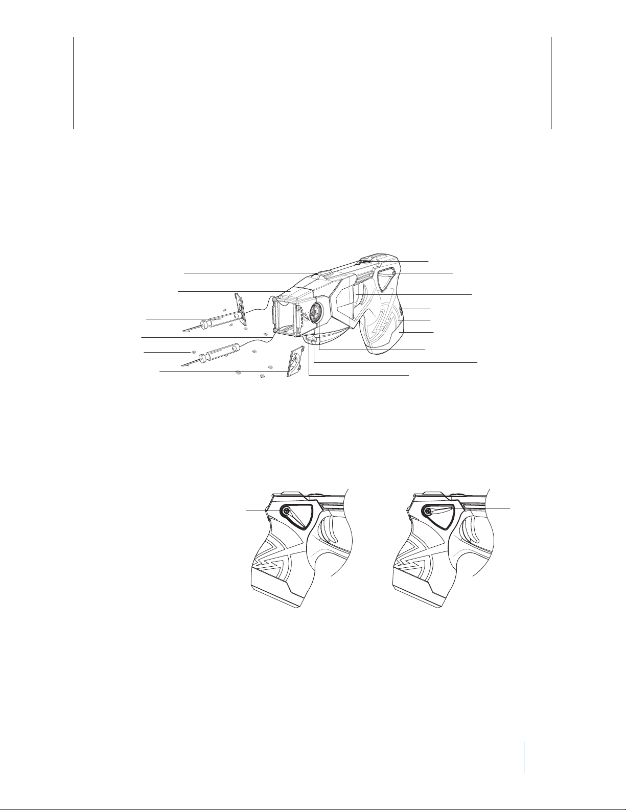
X26P CEW Features
Get to know the X26P CEW:
Mechanical Sights
Illumination Selector
Safety Switch
TASER Cartridge
Probe
Wire
AFIDs
Blast Door
PPM Release Button
Textured Grip Zones
Performance Power
Cartridge Release Tab
Low Intensity Lights (LEDs)
Trigger
Magazine (PPM)
LASER
Note: The serial number is located inside the cartridge bay.
Ensure the CEW is unloaded, the safety is in the down (SAFE) position, and your ngers are away from the
trigger before reading the serial number.
Safety Switch
Ambidextrous safety can be operated from either side of the CEW.
• Safety switch down (SAFE).
• Safety switch up (ARMED)
and ready to deploy.
• Do not block the safety on
one side of the X26P CEW
while attempting to move
it on the other side. This
can break the safety and
disable the CEW.
Down (SAFE)
Up (ARMED)
• With default settings, if the X26P CEW’s safety switch is left in the up (ARMED) position for more than 20 minutes, the system goes into low power mode to reduce the amount of power consumed, and the CEW will not
re. Although the CEW will not re, power is still consumed and will eventually drain the battery if the safety
switch remains in the ARMED position. To re-arm the CEW, shift the safety to the down (SAFE) position, and then
shift it back to the up (ARMED) position.
6
Page 11
TASER X26P CEW User Manual
LASER
The LASER installed in the X26P CEW is oriented with the mechanical sights. At 15 feet (4.6 m), the aiming point is
aligned to the approximate trajectory of a cartridge’s top probe.
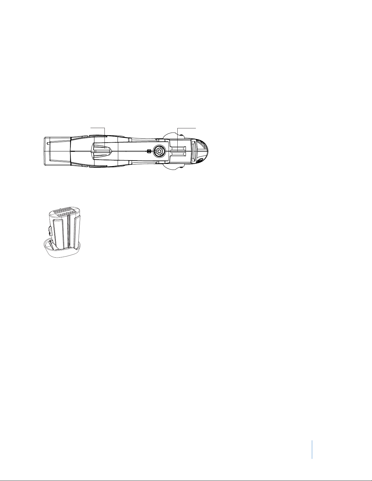
Mechanical Sights
The mechanical sights on the X26P CEW are molded to provide manual aiming of the CEW. The mechanical sights
are set to coincide with a top probe’s trajectory at a 15-foot (4.6 m) distance.
Rear Mechanical SightFront Mechanical Sight
Performance Power Magazine (PPM) Battery Pack
The Performance Power Magazine is a lithium energy cell power supply system for the X26P CEW.
Note: X26P battery packs will not work with the X3 or X26 CEWs, and battery packs designed for the X3 or X26
CEWs will not work with the X26P CEW. Battery packs designed for the X2 CEW will work in the X26P CEW.
Battery packs should be stored in their original packaging, including the dessicant bag, until they are to be used.
Do not store the PPM anywhere that the gold contacts on the top of the PPM may touch metal objects. If you
cause an electrical short between these contacts, the short will drain the battery and may cause the pack itself to
become dangerously hot.
The PPM battery has enough power for approximately 500 ve-second discharges depending on temperature,
environment, use of the ashlight, and other factors. The PPM battery will deplete faster in colder weather than
warm weather. Likewise, the battery will deplete faster with the ashlight active.
For more information on installing the PPM, see Changing the Battery Pack.
Note: Other battery pack options are available for the X26P CEW. See Tactical Performance Power Magazine (TPPM)
Battery Pack, eXtended Performance Power Magazine (XPPM) Battery Pack, Automatic Shut-Down Performance
Power Magazine (APPM) Battery Pack, eXtended Automatic Shut-Down Performance Power Magazine (XAPPM)
Battery Pack, and Signal Performance Power Magazine (SPPM) Battery Pack.
Changing the Battery Pack
To change the battery pack:
1 Point the CEW in a safe direction.
2 Ensure the safety switch is in the down (SAFE) position.
Chapter 3: Features
7
Page 12

TASER X26P CEW User Manual
3 Safely remove the TASER cartridge (do not place any body parts in front of the cartridge). See Unloading
(Chapter 4) for more information.
4 To unload the battery pack, depress the battery pack release button and remove the battery pack from the
handle of the CEW.
Release Button
5 Inspect the battery contacts. Ensure that they are appear in working order and are free from dirt or other
residue that may interrupt the battery connection to the CEW.
6 Install the new battery pack and ensure that it is fully inserted in the X26P CEW. Apply sucient force to
ensure the battery pack is fully seated. When the battery pack seats properly, the release button should
pop out from the recessed portion with an audible click.
Tactical Performance Power Magazine (TPPM) Battery Pack
The optional TPPM has an extension to provide a larger grip on the CEW. The TPPM does not hold an extra cartridge.
Chapter 3: Features
8
Page 13

TASER X26P CEW User Manual
eXtended Performance Power Magazine (XPPM) Battery Pack
To install a TASER standard cartridge in an XPPM:
1 Ensure the cartridge cover is removed. See Removing the Shipping Cover from the Cartridge (Chapter 4).
2 Keeping your hand away from the blast doors, depress the tabs on the sides of the cartridge.
3 Insert the cartridge in the XPPM so the blast doors face forward, toward the front of the CEW.
To remove the cartridge, keeping your hand away from the blast doors, depress the tabs again and pull the cartridge out of the XPPM.
Automatic Shut-Down Performance Power Magazine (APPM) Battery Pack
The optional APPM is a modied battery pack that shuts down the output of the X26P CEW after 5 seconds and
also contains a built-in speaker that alerts you to the impending shut down. The APPM icon will be displayed in the
top left corner of the CID when the CEW detects that an APPM is installed.
Under stressful situations, audio exclusion might prevent you from hearing the alert from the APPM.
The APPM provides an audible beeping alert for the last 2 seconds of a trigger-initiated cycle before automatically
shutting down the cycle. After a 5-second deployment duration, the energy burst will stop even if your nger is
still pulling the trigger switch. The audible beeping alert will continue to sound until the trigger switch is released.
To reenergize the deployed cartridge, rst ensure that your nger is o the trigger switch, and then press the
trigger again.
Replacing the APPM with a Dierent Battery Pack
Your CEW will recognize the APPM as a unique type of battery pack. If you remove the APPM and replace it with
a dierent type of battery pack, the X26P CEW will return to its normal conguration. That is, there will no longer
be an audio alert, and the energy cycle will continue after 5 seconds if your nger is still holding down the trigger
switch. Always conrm that the CEW performs as expected before returning it to duty after changing any battery
pack.
Remove the cartridge before testing the CEW function. See Unloading (Chapter 4) for more information.
eXtended Automatic Shut-Down Performance Power Magazine (XAPPM) Battery Pack
The XAPPM holds an extra TASER standard cartridge like the XPPM and enables the automatic output shut-down
functionality of the CEW like the APPM. See Automatic Shut-Down Performance Power Magazine (APPM) Battery
Pack for more information.
Chapter 3: Features
9
Page 14

TASER X26P CEW User Manual
Signal Performance Power Magazine (SPPM) Battery Pack
The Signal Performance Power Magazine (SPPM) is a battery pack designed to work with devices that are equipped
with Axon Signal technology.
When an X2 or X26P CEW is equipped with an SPPM, shifting the CEW’s safety switch to the up (ARMED) position
causes the SPPM to send a signal. Upon receipt of this signal, a compatible device can perform a pre-programmed
operation.
Note: Your CEW must have rmware version 4.029 or greater to make use of the SPPM’s special features. Without
the rmware update, the SPPM only functions as a battery pack like the PPM. Evidence Sync version 3.15.30
or greater is required to congure the SPPM. See the Evidence Sync User Manual for more information on
rmware updates.
The SPPM transmission begins after the safety switch is shifted to the up (ARMED) position. The SPPM icon will be
displayed in the top left corner of the CID when the CEW has reported its operational status, such as being armed,
to the SPPM. The SPPM then sends a signal that reports the status of the CEW. The signal lasts at least 30 seconds
for the rst occurrence of an event and has a minimum range of up to 100 feet (30.5 meters) line-of-sight.
These are the types of information the SPPM transmission sends:
Event Description
ARMED event The safety switch was shifted to the up (ARMED) position.
ARMED + 10 seconds Ten seconds have elapsed since the safety switch was shifted to the up (ARMED)
position.
Trigger event The trigger was pressed.
Automatic Shut-Down Option
The SPPM can enable the automatic shut-down feature when used in a CEW. The X26P will function the same way
as if it were equipped with the APPM battery pack. See Automatic Shut-Down Performance Power Magazine (APPM)
Battery Pack for more information. To enable the automatic shut-down feature, the agency must congure the
CEW through Evidence.com.
Continued SPPM Transmission in Safe Mode
When the SPPM is installed in a CEW, the device will continue to be powered after the safety switch is shifted to the
down (SAFE) position to allow the SPPM to nish the transmission of its status for the full 30 seconds. The CID will
continue to display the SPPM battery icon and display a message “DO NOT REMOVE BATTERY.” If the safety switch is
shifted to the up (ARMED) position while the device is still sending an SPPM transmission, the device will function
normally but the 30-second timers for each status event will not be reset. Do not remove the SPPM from the CEW
until the device has nished its SPPM transmission and the CID goes blank.
Chapter 3: Features
10
Page 15

TASER X26P CEW User Manual
Updating the SPPM Firmware
To update the SPPM rmware, the device must be connected to a TASER central device over the air (OTA). The CEW
sends a command to the SPPM to start a transmission for this connection when the CEW is in conguration mode.
With the safety switch in the down (SAFE) position, press the selector switch on the top of the X26P CEW. After a
connection with a central device has been established, the CID will change to display the SPPM battery icon and a
message “DO NOT REMOVE BATTERY.” Once the connection to the central device has ended, the CEW will return to
the standard selector mode menu or the CEW will exit conguration mode.
Advanced Central Information Display (CID)
The CID is a monochrome organic light emitting display on the back of the X26P CEW. When the safety switch is
shifted into the up (ARMED) position, the CID will display the battery status.
Energy Cell Indicator:
61-80% Remaining
System Status Icons
The system status icons are designed to inform you of the system status of the X26P CEW. It is the user’s responsibility to conduct proper maintenance, and ensure that the CEW is working properly before any use.
Failure to heed the system status icons could cause serious injury or death.
Major Fault indication. A yellow triangle indicates that the logging, date and time
functions, or ability for the CEW to successfully read the PPM information are not
working properly. The CEW will still produce an electrical output (e.g., the CEW
should still arc and deploy cartridges), but the accountability functions are compromised.
Shift the safety switch to the down (SAFE) position and then to the up (ARMED)
position; the fault may clear.
Whether the fault clears or not, it will be recorded in the Engineering log. If the fault
does not clear, and the CEW is still under warranty, send the CEW to TASER for repair.
Critical Fault indication. A yellow stop sign in the upper-right side of the CID indicates a system failure.
Critical faults are rare. Shift the safety switch to the down (SAFE) position and then
to the up (ARMED) position; the fault may clear.
If the fault does not clear, do NOT attempt to use the CEW. The CEW may need to
be repaired or replaced. See the Product Returns section in this manual for instructions.
Invalid Battery Pack. If you see a blinking exclamation point and battery icon, this
indicates that the CEW did not recognize the battery correctly. Remove the battery
pack and reinsert it. If the error is still present, try another battery pack. If the icon
still displays, the CEW should be sent in for service if it is still under warranty.
An APPM or XAPPM battery pack is installed in the CEW.
Chapter 3: Features
11
Page 16

TASER X26P CEW User Manual
A TASER CAM HD recorder is installed in the CEW. See the TASER CAM HD Recorder
Operating Manual for more information.
A TASER CAM HD recorder with the automatic shut-down feature is installed in the
CEW. This recorder oers an audio warning and shut-down feature like that of an
APPM battery pack.
An SPPM battery pack is installed in the CEW. See Signal Performance Power Maga-
zine (SPPM) Battery Pack for more information.
When you plug the USB download cable into the X2 CEW, the USB connection status icon will appear. See USB Connection Status (Chapter 5) for more information.
DO NOT
REMOVE
BATTERY
When there is an SPPM transmission in the safe mode or the SPPM is connecting for
updates, the warning DO NOT REMOVE BATTERY is displayed.
Battery Level Icons
When the safety switch is in the up (ARMED) position, the CID will display the percentage of battery power
remaining. Remaining capacity will display in 19 percent increments.
When the battery level drops to 20 percent, TASER recommends that the battery pack be replaced.
Battery Battery Battery Battery
81–100% 61–80% 41–60% 21–40%
If the battery capacity is at 1–20 percent, the CID will ash the warning LO BATT on the CID when the safety switch is cycled to the up
(ARMED) position when using a PPM, XPPM, APPM, XAPPM, SPPM or
TPPM.
The LO BATT warning will be displayed when the battery capacity is
between 1–40 percent for TASER CAM HD.
If the battery capacity is at 1–20 percent, this icon displays in the lower-right portion the CID.
Battery
01–20%
Blinking
When the TASER CAM HD battery is depleted, the CID will ash the
warning RECHARGE BATTERY on the CID when the safety switch is
cycled to the up (ARMED) position.
Chapter 3: Features
12
Page 17

TASER X26P CEW User Manual
When the PPM, TPM, APPM, XPPM, XAPPM, or SPPM battery pack is
depleted, the CID will ash the warning CHANGE BATTERY on the CID
when the safety switch is cycled to the up (ARMED) position.
Battery
Depleted
Spark Duration
The CID displays a count indicating how many seconds the deployment cycle lasts. The CEW will count up from the
number 1 up to 99. At 99 seconds, the count will restart at 1.
Sample CID Displays
The CID below shows the X26P CEW with a TASER CAM HD recorder installed and a battery capacity of 61–80
percent.
TASER CAM HD
Recorder
Battery:
61-80% Remaining
The CID below shows a CEW that has been discharging for 4 seconds, with a battery pack that is at 41–60 percent
capacity.
Count
Battery:
41- 60% Remaining
The CID below shows a CEW with an APPM battery pack installed that has a battery capacity of 61–80 percent.
APPM Installed
Battery:
61-80% Remaining
The CID below shows a CEW with a battery pack error.
Invalid
Battery Pack
The CID below shows a CEW that is 4 seconds into an energy burst, has a battery pack that is 81–100 percent
charged, and a major fault with the CEW.
Major Fault
Count
Battery:
81- 100% Remaining
Chapter 3: Features
13
Page 18

TASER X26P CEW User Manual
LED Flashlight
The X26P CEW has a high intensity white LED to aid the user in dark environments.
Selector Switch (LASER and LED Flashlights)
You can select four modes of illumination when using the X26P CEW. To change the illumination setting:
1 Point the CEW in a safe direction.
2 Ensure the safety switch is in the down (SAFE) position.
3 Keeping your hand away from the blast doors, depress the tabs on the sides of the cartridge and remove.
4 Press and hold the selector switch for approximately 1 second until the CID display illuminates.
Note: Using pens or paper clips to press the selector switch may damage it. Only use your nger to press
the selector switch.
5 Press and release the selector switch to toggle through the 4 available settings until the setting you desire
is designated on the CID. Stop when the setting you desire is displayed.
OO: Neither the LASER nor the Flashlight will illuminate.
LO: Only LASER will illuminate
OF: Only Flashlight will illuminate
LF: LASER and Flashlight both illuminate
The selected mode displays for 5 seconds, and will be the default mode the next time the safety switch is moved
to the up (ARMED) position.
The selector switch may also be used to activate the Stealth Mode, which will shut o the LASER and ashlight, and
dim the CID display. To do this, press the selector switch when the safety is in the up (ARMED) position. To take the
CEW out of Stealth Mode, press the selector switch again or shift the safety to the down (SAFE) position. You will
have to reactivate the Stealth mode each time you place the safety in the up (ARMED) position.
Chapter 3: Features
14
Page 19

TASER X26P CEW User Manual
Trigger Switch
Unlike a rearm trigger, the X26P CEW trigger is a momentary electrical switch. The switch is operational only
when the safety switch is in the up (ARMED) position. Pulling and releasing the trigger switch will result in an
approximately 5-second discharge cycle unless the safety switch is shifted to the down (SAFE) position to discontinue the 5-second cycle. Pulling and holding the trigger switch for more than 5 seconds will result in a continuous
discharge until the trigger switch is released, or the battery is depleted—whichever comes rst.
An X26P CEW equipped with the APPM battery pack is limited to 5-second discharges and emits an audio alert 2
seconds before the end of the cycle. See Automatic Shut-Down Performance Power Magazine (APPM) Battery Pack
for more information. An X26P CEW equipped with an SPPM can be congured to enable the CEW’s automatic
shutdown feature. See Signal Performance Power Magazine (SPPM) Battery Pack for more information.
In the event of an accidental discharge, immediately move the safety switch to the down (SAFE) position to
stop the discharge cycle.
Trigger Switch
Chapter 3: Features
15
Page 20

Chapter 4: Cartridges & CEW Operation
Removing the Shipping Cover from the Cartridge
Cartridges are sold separately from the CEW. Cartridges are shipped with a shipping cover in place. Carefully remove these covers before attempting to load a cartridge into the X26P CEW. Be careful to not allow any body part
to be in front of the cartridge. Static electricity can discharge a cartridge, and injuries have occurred. A cartridge
cannot be loaded into the CEW with the cover in place. Once the cartridge cover is removed, it can be disposed of.
1 Before removing the covers, make sure the front of the cartridge does not point at any body part or at
anyone.
2 Carefully place the cartridge with cover face down (blast door down) onto a stable/solid surface, i.e., a table.
3 Place your index and middle ngers onto the sides of the cartridge where the wedges/electrodes are locat-
ed and place your thumbs onto the locking portions of the cover.
4 Push in with your ngers and pull outward with your thumbs and the cartridge will pop upward, releasing
it from the cover.
Note: The cartridge may pop upward quickly when the pressure is released from the locking portions of
the cover.
15, 21, LS, and XP25 TASER Cartridges
Never attempt to open or modify a TASER cartridge. Tampering with a live TASER cartridge could cause it to re
or malfunction (which may result in serious injury).
Handle all TASER cartridges with care. Probes may deploy unexpectedly if exposed to physical shock, or static
electricity.
TASER cartridges should be kept away from conditions known to create an electrostatic discharge, such as rubbing
cloth (e.g., jacket liner or uniform pants) across a cartridge in an environment known to create static shocks.
Cartridge blast doors can be knocked o the front of a cartridge. Because those cartridges cannot be relied upon
to consistently discharge, TASER recommends removing those cartridges from service. Attempting to deploy a
cartridge with no blast doors could result in a charge being created and held in the wires. Any conductive material
16
Page 21

TASER X26P CEW User Manual
that comes into contact with the front of the cartridge, even after the cycle has ended, could draw the charge to
the ignition pin and deploy the probes.
TASER oers a Blast Door Repair Kit that can be used to replace blast doors that come o. Cartridges with replaced
blast doors should only be used for training and should not be deployed to the eld. Go to www.axon.com for
more information on the Blast Door Repair Kit.
AFID
Every time a TASER cartridge is deployed, approximately 20–30 small confetti-like Anti-Felon Identication (AFID)
tags are ejected. Cartridges can be assigned to individual users, as each is serialized. Each AFID tag is printed with
the corresponding serial number of the cartridge deployed, allowing determination of which user deployed the
particular cartridge.
Load the TASER Cartridge
Never place your hands or ngers in front of the cartridge. This is especially important when loading and unloading the cartridge. Serious injury could result. When loading and unloading always hold the cartridge on
the sides or top.
TASER cartridges are shipped with a shipping cover in place. Remove these covers before attempting to load a
cartridge into an X26P CEW. See Removing the Shipping Cover from the Cartridge for more information.
Loaded
Loading
1 Point the CEW in a safe direction.
Unloaded
2 Ensure that the safety switch is in the down (SAFE) position.
3 Make sure the protective shipping cover is removed from the TASER cartridge.
4 Keeping your hand away from the blast doors, place the cartridge (with the cartridge cover removed) into
the front of the CEW until an audible click is heard.
5 Verify that the cartridge is secure by pulling on the sides of the cartridge.
Chapter 4: Cartridges & CEW Operation
17
Page 22

TASER X26P CEW User Manual
Unloading
1 Point the CEW in a safe direction.
2 Ensure that the safety switch is in the down (SAFE) position.
3 Keeping your hand away from the blast doors, depress the tabs on the sides of the cartridge and remove.
The 15-, 21-, and 25-foot (4.6-, 6.4-, and 7.6-meter, respectively) TASER cartridges are specically designed so there
is no “up” or “down” position – enabling you to quickly reload one in a stressful situation without worrying about
putting it in upside down.
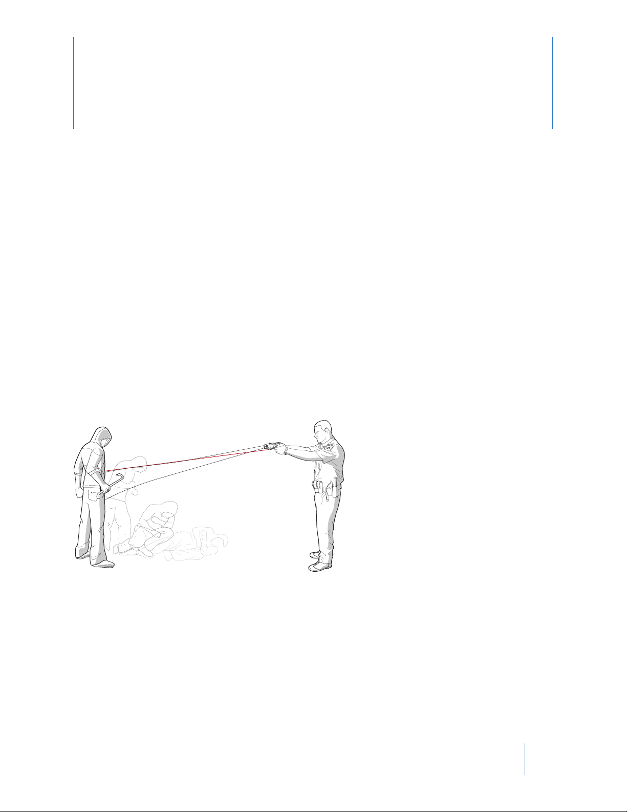
Aiming and Probe Placement
Level Tilted
For most deployments, hold the CEW level. Do not tilt the CEW unless it is necessary to do so to align the CEW with
the target.
All TASER CEW deployments should be in accordance with current TASER training and warnings, and department
training, policies, and procedures.
Normally, aim the LASER at the preferred target areas of the body, which are the lower center-mass (below the
chest) and legs when the subject is facing you, or the subject’s back if the subject is turned away from you.
When possible, avoid intentionally targeting the CEW on sensitive areas of the body such as the head,
throat, chest/breast, or known pre-existing injury areas without legal justication.
The top probe impacts the target near the LASER beam; however, the probe impact distance from the LASER will
vary depending on the distance between the CEW and the target, type of cartridge, etc. At 15 feet (4.6 m), the
LASER’s position corresponds to the trajectory of a 25 feet (7.6 m) cartridge’s top probe at the same range.
The bottom probe impacts at an 8-degree angle from the top probe. This results in a spread of approximately 1
foot (0.3 m) for every 7 feet (2.1 m) of distance from the CEW. Greater probe spread increases eectiveness.
“Silence Is Golden”
The TASER CEW’s electrical current is relatively quiet when both probes make direct contact with a human or an
animal. In contrast, some practice conductive targets are loud because the energy is arcing in the air.
If electrical current is loud during eld deployment and the subject is not reacting as expected, the electrical cir-
Chapter 4: Cartridges & CEW Operation
18
Page 23

TASER X26P CEW User Manual
cuit may not be completed or the current may be shorting out and may not be eective. Deploy a second cartridge
or consider other options in accordance with your agency’s policies.
Potential Causes of Reduced or No Eectiveness
• Loose or Thick Clothing. If the probes lodge in clothing and are too far away from the subject, CEW eective-
ness is reduced and can be eliminated.
• Miss or Single Probe Hit. The current must pass between the probes. If one probe misses, a second cartridge
should be deployed if practical and legally justiable. Also, using the X26P CEW in the drive-stun mode as described below may complete the circuit between the single probe and the CEW electrode.
• Low Nerve or Muscle Mass. If the probes impact in an area where there is very little muscle mass (e.g., the side
of the rib cage), the eectiveness can be signicantly diminished.
• Limited Probe Spread. Probe spreads of less than 4–9 inches (10–23 cm) (including drive-stun) may result in
little or no eect and become primarily a pain compliance option.
• Wires Break. If a wire breaks (e.g., during a struggle), the current will not ow to the probes and an additional
deployment may be required. Drive-stun may still be available.
Do not become over-dependent on the TASER CEW. No force option, including CEWs, is 100% eective in
every situation. Do not deploy the CEW without following your department policies and procedures.
Electrodes
The front of the X26P CEW has 2 metal electrodes. These electrodes direct the charge to the electrodes on the
cartridge to initiate deployment of the probes. In addition, the electrodes provide the ability to use the X26P CEW
in a “drive-stun” mode as a traditional stun-gun type CEW.
Electrode
Electrode
Drive-Stun Backup
Drive-stun capability is available with or without a TASER cartridge installed. To apply a drive-stun, place the safety
in the up (ARMED) position and pull the trigger. The drive-stun mode is not designed to cause incapacitation and
generally becomes primarily a pain compliance option. Probe deployment is usually considered more desirable if
incapacitation is the desired objective, even at close range. Some of the advantages of probe deployment include:
• Drive-stun is only eective while the CEW is in contact with the subject or when pushed against the subject’s
clothing. As soon as the CEW is moved away, the energy being delivered to the subject stops. Deploying the
probes allows the user to separate from the subject while maintaining control.
• Due to automatic reex actions, most subjects will struggle to separate from the CEW. Each time the CEW
comes back in contact with the subject, another set of marks may be visible on the subject’s skin. Using the
probes allows for one point of discharge.
Chapter 4: Cartridges & CEW Operation
19
Page 24

TASER X26P CEW User Manual
• If the probes are deployed, even at very close range, the user may drive-stun to another portion of the body
that is further away from the probes, thereby increasing the possibility of inducing incapacitation.
If the drive-stun is not eective, evaluate the location of the drive-stun, consider an additional cycle to a dierent
pressure point, or consider alternative force options in accordance with your agency’s policies. When using the
drive-stun, push (drive) the front of the X26P CEW rmly against the body of the subject. Simply “touching” the
X26P CEW against the subject is not sucient. The subject is likely to recoil and try to get away from the CEW. It is
necessary to aggressively drive the front of the CEW into the subject for maximum eect.
Recommended Drive-Stun Areas for Maximum Eect
Use the X26P CEW pursuant to your agency’s policies and procedures. For maximum eectiveness, drive the X26P
CEW into the highlighted green areas as outlined below.
Suggested pressure points are highlighted in the green areas. Use care when applying the drive-stun to the neck or groin (yellow and red areas – users should only target these areas when they are defending themselves against a violent attacker). Stay
away from the trachea and back of the neck. The trachea is soft tissue and could easily
be crushed. The cervical portion of the spine is very sensitive to pressure. Also, care
should be taken when applying a drive-stun to the pelvic triangle to avoid the possibility of crushing the testicles. Because of the risk of injury, these areas should not be
used on subjects who do not pose an immediate threat.
Refer to your department’s policy regarding drive-stuns in these and other sensitive areas.
Chapter 4: Cartridges & CEW Operation
20
Page 25

Chapter 5: Maintenance/Troubleshooting
Function Test
TASER recommends conducting a function test every 24 hours or prior to the start of your shift for your individually issued X26P CEW. The function test is done to verify that the CEW’s core electronics are working properly.
Function Test Instructions
1 Point the CEW in a safe direction.
2 Shift the safety switch to the down (SAFE) position.
3 Remove the TASER cartridge. A function test should never be conducted with a TASER cartridge in the CEW.
4 Ensure that your ngers and no other part of your body are in front of the X26P CEW.
5 Shift the safety switch to the up (ARMED) position.
6 Pull the trigger and visually conrm sparking across the electrodes. Allow the full 5-second cycle to run.
View the arc from the top or side of the CEW. Do not point the CEW at your face or have it near your
face.
7 Look at the CID display and verify the following:
• No fault icons display on the CID.
• LO BATT is not displaying on the CID.
If any of the above verications fail, return the unit to your agency’s CEW technician for service.
8 Shift the safety switch to the down (SAFE) position.
21
Page 26

TASER X26P CEW User Manual
What to Do Following CEW Use
Considerations for Handling Used Probes
Each agency will establish its own procedure for probe removal, collection, biohazards, evidence collection and
maintenance. Treat probes that have penetrated the body as contaminated needles (biohazard). Remember, however, that the probes may also be valuable evidence.
If the probes must be removed from the subject, follow all department policies and procedures, including for
handling biohazards.
Below are suggested methods for probe removal.
• Grab the probe rmly and quickly pull it straight out. Do not twist the probe as the barbed tip may cause additional injury.
• If the probes are not going to be collected and maintained for evidence, carefully place used probes sharp-tip
rst into a sharps container, secure in place, and place in a secure location where no one will accidentally touch
the probes.
• Once the subject is restrained, prior to removing the probes, evaluate the need for medical attention as you
would with any other use-of-force incident.*
• Take photos of any injuries, place the photos into evidence.*
• Collect the expended cartridge, probes, and AFIDs and place them into evidence.*
* As directed by department policy. The TASER training materials provide additional information on forensic evidence collection procedures. The probes, wires, AFIDs, and cartridge can yield important forensic evidence if
properly collected, maintained, and analyzed. Ensure that the CEW is downloaded and the downloaded logs are
collected per your agency’s policy.
Eects on Animals
The M26 and X26 CEWs can be an eective option for dealing with aggressive animals and have generally been
successful in most deployments. The X26P CEW uses similar technology, but does not yet have the same service
record as the previous models.
Note: If a probe deployment completed circuit is initiated and maintained, the aggressive animals are usually
incapacitated/stunned momentarily in M26 and X26 deployments, but recover quickly. The vast majority
of the animals quickly left the scene and broke the wires.
If deployed on a domestic animal, consider having animal control available to restrain the animal.
Chapter 5: Maintenance/Troubleshooting
22
Page 27

TASER X26P CEW User Manual
Police/Military K-9 Caution
CEW operators and K-9 ocers must work closely together to develop policies and procedures for deploying the
CEW when a K-9 is present. If a K-9 bites a probe or bites the suspect between the probes, the K-9 could receive a
shock. This could have a negative impact on the future duty use of the K-9.
Uploading Firmware Revisions
The X26P CEW internal rmware provides functionality for all aspects of the CEW. The rmware can be upgraded
to the most recent version by using an X26P/X2 CEW Dataport Download Kit (purchased separately) and Evidence
Sync software (Online or Oine).
Do not remove the USB cable or press the reset button on the dataport USB pack during the reprogramming cycle.
Dataport Download Kit
Optional download kits are available to permit agencies to access the deployment information in the X26P CEW
memory through the Evidence.com Services or the Sync Oine or Online Client software.
Note: If you have a TASER CAM HD recorder, please see the TASER CAM HD Recorder Operating Manual and the
Evidence Sync User Manual for downloading instructions.
The X26P CEW uses a USB adapter (download cable) to connect to any Windows XP or Windows 7 computer. The
simplicity of USB makes using the dataport download kit an easy, fast process. The cable connects to the CEW
through the battery compartment.
USB Connection Status
The USB icon will ash on the CID when the CEW is searching for the Evidence Sync client software. The icon will
display solid when the CEW is connected to the software.
Evidence Sync Oine Software
If you do not have an Evidence.com account, the Evidence Sync software can be used in the Oine mode to download the simplied Event log to your local computer and print it. The Evidence Sync Oine software will not enable
you to view the full Trilogy log.
Trilogy Log
Upon upload to Evidence.com, the system collects the information into 3 related data logs called the Trilogy logs:
• Event log
• Pulse log
• Engineering log
The data set from the Trilogy log is uploaded securely to Evidence.com, where the information is encrypted, stored
Chapter 5: Maintenance/Troubleshooting
23
Page 28

TASER X26P CEW User Manual
securely, and organized into dashboards that allow your agency to easily monitor the usage and system status of
your entire arsenal of X26P CEWs.
Upon upload to Evidence.com, the system displays the information from the Event and Pulse logs. Your type of
Evidence.com account will determine what data can be viewed from these logs.
Event Log
The Event log tracks events and may help protect a user from claims of excessive use of force by providing documentation of the time and date for each CEW deployment. The Event log also provides agencies with a powerful
management tool to track usage patterns and help prevent misuse. You do not need to download the X26P to
Evidence.com services to obtain the Event log – this can be downloaded directly to your PC using the Evidence
Sync (Oine) software.
The Event log includes the following information for the most recent (approximately) 16,000 entries:
• Each entry contains the date and time of each event.
• Entries include Armed, Safe, Trigger, USB connection, PowerSave mode, rmware updates, time synchronizations, PPM changes, SPPM end of transmission, etc.
• The duration of each Trigger event.
• The duration of each Safe event (how long the CEW was armed when the safety switch was moved to the down
[SAFE] position).
• The internal temperature is shown for Armed and Safe events.
• Battery percentage is shown for all armed session events (Armed, Trigger, Safe).
When the log lls to approximately 16,000 entries, it will delete the oldest 4,096 records and write new ones. This
process will continue in 4,096-record increments.
Pulse Log
The Pulse log records any pulse activity. The records include how long the CEW was discharged, and the charge of
every pulse.
Engineering Log
The Engineering log monitors the performance of key sub-systems within the X26P CEW. It provides alerts if a subsystem is not performing properly and if maintenance is advisable. Any internal circuitry errors that occur inside
the X26P CEW are written to this log. This information is used for diagnostics.
Time Synchronization
The CEW has a real-time clock powered by the battery pack and an internal battery as well. The CEW should keep
accurate time even when the battery pack is removed.
Chapter 5: Maintenance/Troubleshooting
24
Page 29

TASER X26P CEW User Manual
Every time the X26P CEW is connected to Evidence.com services, the system will perform a time synchronization.
The conversion to local time, including adjustments to daylight savings time, are all computed by Evidence Sync
software. There is no need to program the X26P CEW to local time or to reprogram the CEW to daylight savings
time.
Note: In Evidence Sync Oine mode, if your computer time is incorrect, the incorrect time will be displayed in
your Evidence Sync-generated report.
X26P CEW Maintenance and Care
Each agency should establish a maintenance and handling program.
The X26P product is a sensitive piece of electronic equipment, and should be handled with care. Avoid dropping an X26P CEW. Do not use an X26P CEW that has a cracked handle.
• Check the battery pack regularly. Replace it when the battery percentage reaches 20%.
• Occasionally wipe out the X26P cartridge deployment bay with a dry cloth. Multiple cartridge rings create
carbon build-up (particularly after training courses) that should be removed.
Do not wipe out the X26P cartridge bay immediately after the CEW has been red as you might receive
a latent short electrical shock. Wait at least 5 minutes after the last discharge of the X26P CEW before
wiping out the bay.
• Secure the X26P CEW in a protective holster when the CEW is not in use.
• Function test the CEW before each shift.
• Update the CEW’s rmware when updated rmware is released.
• Download your X26P CEW data to Evidence.com services or your local PC at least once per quarter and always
before sending the CEW for repair or warranty work.
• Avoid immersing the X26P CEW in water or exposing the X26P CEW to excessive moisture or water.
• See the troubleshooting guide at www.axon.com for additional maintenance instructions.
Check expiration of TASER cartridges (5-year expiration date is listed on the base of the cartridge). Do not use an
expired TASER cartridge in the eld. They should only be used for training.
Dropped or Wet X26P CEW
Do not immerse the CEW in water. If your CEW has been submerged in water or exposed to a signicant
amount of water for an extended time, remove it from service and contact TASER.
Follow these steps for a CEW exposed to some moisture but not submerged in water.
1 Point the CEW in a safe direction and away from your body.
2 Shift the safety switch to the down (SAFE) position.
3 Safely remove the battery pack.
4 Safely remove the TASER cartridge.
5 Let the CEW dry out.
Dry the X26P CEW thoroughly (at least 24 hours). Do not use an external heat source such as a microwave oven or hair dryer to dry the X26P CEW.
6 Point the CEW in a safe direction and away from your body and ensure that the safety switch is in the down
Chapter 5: Maintenance/Troubleshooting
25
Page 30

TASER X26P CEW User Manual
(SAFE) position.
7 Safely reinstall the battery pack.
8 Wait 1 minute before proceeding to the next step. Conrm that the CEW or battery pack is not getting
warm.
9 Shift the safety to the up (ARMED) position.
• If the CEW discharges without the trigger being pressed, shift the safety switch to the down (SAFE) position immediately, remove the battery pack, return the CEW to Axon Enterprise per the return policies
if the CEW is still under warranty.
• If the CEW does not discharge, go to step 10.
10 Look at the CID to ensure the X26P CEW is functioning properly and the CID is not showing any fault icons.
11 Conrm that the LASER and ashlight are working properly.
12 Press the trigger switch to test the functioning. Conduct three complete 5-second discharges to conrm
the proper pulse rate and observe that the cycle stops at 5 seconds. See the instructions under Function
Test for more information.
13 If the trigger switch does not work, or if the CID shows a critical error icon, shift the safety switch to the
down (SAFE) position immediately, remove the battery pack, and return the CEW to Axon Enterprise per
the return policies if the CEW is still under warranty.
14 If the CEW does function normally, shift the safety switch to the down (SAFE) position.
15 Connect the CEW to Evidence Sync and conrm the internal time is correct. See the Evidence Sync User
Manual for more information.
16 Conrm that the 3 trigger discharges were recorded properly in the download records.
17 Return the CEW to service.
Online Troubleshooting Guide
A troubleshooting guide is available by visiting www.axon.com. If you need product support on accessories or
have any other questions, please contact customer service online at www.axon.com or at:
U.S.: 1-800-978-2737
Australia: 1800512069
Other international: +1 480-463-2170
Product Returns
To return a TASER product for service, rst follow the procedures at www.axon.com.
Always perform a complete download from the X26P CEW before returning it for warranty or repair work.
Any data information will be lost during servicing work performed by Axon.
If the TASER CEW has been exposed to bodily uids or other bio-hazards, please contact the customer service department at U.S.: 1-800-978-2737, Australia: 1800512069, other international: +1 480-463-2170 for
specic instructions BEFORE returning the X26P CEW.
Chapter 5: Maintenance/Troubleshooting
26
Page 31

Chapter 6: Optional Accessories
Evidence.com Services
You can upload the data from your X26P CEW to Evidence.com or Evidence.com Lite services. Evidence.com Lite
is free and allows downloading the X26P CEW, viewing the Event and Pulse logs, and updating the CEW software.
The full Evidence.com pay service allows you to manage video records in addition to your CEW records. Visit www.
evidence.com for details.
Evidence Sync Oine Software
The Evidence Sync software can be used in the Oine mode for CEW users who do not have an Evidence.com
account. EVIDENCE Sync Oine enables you to download the Event log to your local computer and print it. Visit
www.evidence.com or www.axon.com for details.
TASER CAM HD Recorder
The TASER CAM HD recorder allows users to capture vital information prior to, during, and after deployment or
potential deployment of the X26P CEW. The TASER CAM HD recorder is an audio-video recording device inserted
into a rechargeable X26P CEW power supply that replaces the standard battery pack and is compatible with the
X26P CEWs. The TASER CAM HD recorder is activated when the safety switch is in the up (ARMED) position. There
is a boot-up time delay of approximately 2 seconds after the safety switch is moved to the up (ARMED) position
before it starts to record.
The TASER CAM HD battery is rechargeable and is capable of approximately 100 ve-second rings when completely charged. Charging is accomplished through a 110-volt wall adapter through the USB cable.
27
Page 32

TASER X26P CEW User Manual
The TASER CAM HD can record approximately 1 hour of video at maximum resolution before recording over previous les (continuous loop system).
Video and audio is downloaded via a USB cable and Evidence Sync software to your local computer or to Evidence.
com services.
There also is an automatic shut-down (AS) version of the TASER CAM HD recorder that emits an alarm and shuts
down the energy cycle after 5 seconds, like the APPM and XAPPM battery packs.
Holsters
Several holsters are designed for use with the X26P CEW. Both right- and left-handed congurations are available.
Visit our website at www.axon.com for details.
Chapter 6: Optional Accessories
28
Page 33

Chapter 7: Additional Items
Additional Information
New TASER brand products are under development. Visit our website at www.axon.com for the latest information.
See the current product warnings, training materials, licensing agreements, and specication sheets for more information about your TASER product.
Product functions and specications may change without notice and the actual product may vary from the illustrations in this manual.
TASER Training Academy
The TASER Training Academy is designed to provide training on the use of TASER-brand CEWs. Training is geared
toward the special needs of law enforcement ocers, correctional ocers, medical personnel, the military, professional security, and private citizens. CEW functions, medical issues, device maintenance, and personal safety are
just a few of the topics covered in the oered courses.
Located at Axon’s headquarters in Scottsdale, Arizona, the TASER Training Academy features a state-of-the-art
classroom facility complete with 48 work stations equipped with power and Internet access, and safety mats.
We “ght like we train.” It is for this reason that we emphasize hands-on, interactive and scenario-based training.
Most of our courses involve some degree of physical activity and participation. We make reasonable eorts to
simulate real-life stress and circumstances, to provide realistic training to better prepare the student for success in
the eld. Through the use of our Simulation Training Suits, we promote sound use of force judgment, tactics and
follow up procedures.
Our cadre of instructors consists of active and former law enforcement ocers and military trainers. Many are internationally recognized experts in use of force at all levels with extensive training backgrounds.
All of our instructors are committed to providing high-level training and to forming lasting relationships to support our students long after they leave the TASER Training Academy.
For more information visit our website www.axon.com or give us a call at 1.800.978.2737.
Courses:
• TASER Conducted Electrical Weapon Instructor Course
• TASER Online User Course
• TASER Master Instructor Course
• TASER Technical Solutions and Investigations Course
29
Page 34

TASER X26P CEW User Manual
• TASER Use of Force, Risk Management and Technical Solutions Seminar
Medical Research
TASER CEWs are among the most extensively studied force options. Numerous CEW-related medical and eld
studies have been published. For more information go to www.axon.com.
Radio Waves
An SPPM transmission is in the frequency range of 2402 to 2480 MHz.
Changes or modications to the equipment not expressly approved by the manufacturer could void the product
warranty and the user’s authority to operate the equipment.
Your wireless device is a radio transmitter and receiver. It is designed and manufactured not to exceed the emission limits for exposure to radio frequency (RF) energy set by the Federal Communications Commission (FCC)
of the U.S. Government. These limits are part of comprehensive guidelines and establish permitted levels of RF
energy for the general population. The guidelines are based on standards that were developed by independent
scientic organizations through periodic and thorough evaluation of scientic studies. The standards include a
substantial safety margin designed to assure the safety of all persons, regardless of age and health. Before a device model is available for sale to the public, it must be tested and certied to the FCC that it does not exceed the
limit established by the government‐adopted requirement for safe exposure. This equipment has been tested and
found to comply with the limits for a Class B digital device, pursuant to part 15 of the FCC Rules. These limits are
designed to provide reasonable protection against harmful interference in a residential installation. This equipment generates, uses and can radiate radio frequency energy and, if not installed and used in accordance with
the instructions, may cause harmful interference to radio communications. However, there is no guarantee that
interference will not occur in a particular installation. If this equipment does cause harmful interference to radio or
television reception, which can be determined by turning the equipment o and on, the user is encouraged to try
to correct the interference by one or more of the following measures:
Reorient or relocate the receiving antenna.
Increase the separation between the equipment and receiver.
Connect the equipment into an outlet on a circuit dierent from that to which the receiver is connected.
Consult Axon Enterprise Customer Service for help.
FCC/IC NOTICE: This device meets the body worn human exposure limits found in OET Bulletin 65, 2001, and ANSI/
IEEE C95.1, 1992. Proper operation of this equipment according to the instructions found in this guide will result in
exposure substantially below the FCC’s recommended limits. To comply with the FCC and ANSI C95.1 RF exposure
limits, this device has been tested for compliance with FCC RF Exposure limits in the typical conguration. The
radiated output power of this wireless device is far below the FCC radio frequency exposure limits.
This device complies with part 15 of the FCC Rules. Operation is subject to the following two conditions: (1) This
device may not cause harmful interference, and (2) this device must accept any interference received, including
interference that may cause undesired operation.
This device complies with Industry Canada licence-exempt RSS standard(s). Operation is subject to the following
two conditions: (1) this device may not cause interference, and (2) this device must accept any interference, including interference that may cause undesired operation of the device.
Chapter 7: Additional Items
30
Page 35

TASER X26P CEW User Manual
Le présent appareil est conforme aux CNR d’Industrie Canada applicables aux appareils radio exempts de licence.
L’exploitation est autorisée aux deux conditions suivantes : (1) l’appareil ne doit pas produire de brouillage, et (2)
l’utilisateur de l’appareil doit accepter tout brouillage radioélectrique subi, même si le brouillage est susceptible
d’en compromettre le fonctionnement.
THIS MODEL DEVICE MEETS THE GOVERNMENT’S REQUIREMENTS FOR EXPOSURE TO RADIO WAVES.
Section 7.1.3 of RSS-GEN
This Device complies with Industry Canada License-exempt RSS standard(s). Operation is subject to the following
two conditions: 1) this device may not cause interference, and 2) this device must accept any interference, including interference that may cause undesired operation of the device.
Cet appareil est conforme aux normes d’exemption de licence RSS d’Industrie Canada. Son utilisation est soumise
aux conditions suivantes : 1) cet appareil ne doit pas causer de brouillage, et 2) doit accepter tout brouillage, y
compris le brouillage pouvant entraîner un fonctionnement indésirable.
Section 7.1.2 of RSS-GEN
Under Industry Canada regulations, this radio transmitter may only operate using an antenna of a type and maximum (or lesser) gain approved for the transmitter by Industry Canada. To reduce potential radio interference to
other users, the antenna type and its gain should be so chosen that the equivalent isotropically radiated power
(e.i.r.p.) is not more than that necessary for successful communication.
Conformément à la réglementation d’Industrie Canada, le présent émetteur radio ne peut fonctionner qu’au moyen d’une antenne d’un seul type et d’un gain maximal (ou inférieur) approuvé pour l’émetteur par Industrie Canada. Dans le but de réduire les risques de brouillage radioélectrique pour les autres utilisateurs, il faut choisir le
type d’antenne et son gain de sorte que la puissance isotrope rayonnée équivalente (p.i.r.e.) ne dépasse pas celle
requise pour établir une communication satisfaisante.
THIS MODEL DEVICE MEETS THE GOVERNMENT’S REQUIREMENTS FOR EXPOSURE TO RADIO WAVES.
Declaration of Conformity
Axon Enterprise declares that this Axon system is in compliance with the requirements and other relevant provisions of the RTT&E Directive 1999/5/EC regarding radio and telecommunications equipment and the Directive
2014/30/EU regarding electromagnetic compatibility. A copy of the original Declaration of Conformity can be
found at www.axon.com.
Chapter 7: Additional Items
31
Page 36

Product functions and specications may change without notice and the actual product may vary from the illustrations in this manual.
Windows is a trademark of Microsoft Corporation.
, Axon, Axon Body 2, Axon Flex, Axon Signal, Evidence.com M26, TASER CAM, Trilogy, X2, X3, X26, X26P, XP25, TASER, ®, and © are
trademarks of Axon Enterprise, Inc., some of which are registered in the US and other countries.
For more information, visit www.axon.com/legal. All rights reserved. © 2017 Axon Enterprise, Inc.
MMU0042 Rev: F
 Loading...