

Page 1
Page 2

Page 3
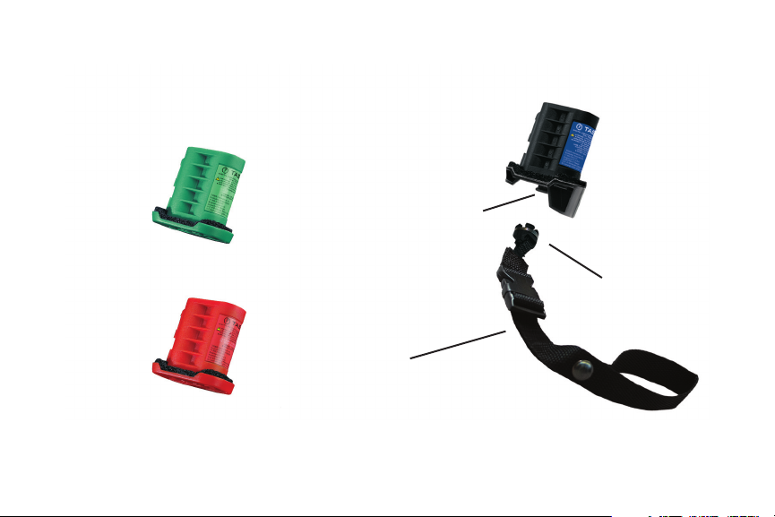
Congure Controlled DPM (CCDPM)
Controlled Digital Power Magazine (CDPM)
Safety Lock
De-Congure Controlled DPM (DCDPM)
Wrist Strap
TASER® CDPM Operating Manual • MMU0014 Rev: B
Safety Key
3
Page 4
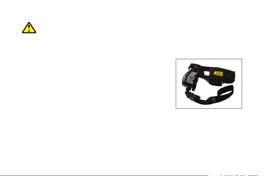
WARNING: Lithium Batteries may explode or cause burn if disassembled, recharged or
exposed to water, re or high temperature. For use in TASER X26 devices only.
THE TASER® CONTROLLED DIGITAL POWER MAGAZINE (CDPM™)
The TASER Controlled Digital Power Magazine (CDPM) is an option
for the law enforcement X26™ device. The CDPM has the same
function as the Digital Power Magazine (DPM™), but the CDPM
features a safety lanyard/wrist strap designed to secure the device
to the ocer. If a prisoner or suspect takes the X26 device away
and breaks the connection for more than two seconds, the system
is designed to deactivate the X26 device. An activation code is then
necessary to reactivate the device for future use.
Note: The two seconds required to fully disable the device is a functional design that allows for full
X26 device operation if a timely reconnect is initiated after an unintended disconnect.
TASER® CDPM Operating Manual • MMU0014 Rev: B
4
Page 5
The CDPM is designed to work with law enforcement X26 devices. It can be used with the X26
Citizen device (X26C™); however, the activation code feature will not function.
An X26 device, congured for a CDPM, operates the same way as other X26 devices
with one major dierence: if the device detects that either the CDPM or the lanyard/
wrist strap (Figure 1) has been removed or disconnected for more than two seconds,
then you must enter an activation code for the device to work.
In addition to the CDPM, the CDPM conguration system includes two specialized
DPMs (Figures 2 and 3); a green Congure Controlled DPM (CCDPM™) and a red
De-Congure Controlled DPM (DCDPM™). The CCDPM is used
to activate a code enabled prole in the X26 device. In the code
enable mode, the X26 device will work with all TASER digital power
magazines. The DCDPM will convert a code enabled X26 device
back to its original conguration, whereby an activation code is not
required.
Figure 2
TASER® CDPM Operating Manual • MMU0014 Rev: B
Figure 1
Figure 3
5
Page 6

PHYSICAL DESCRIPTION
The CDPM has a safety lock on its base. The lanyard/wrist strap is attached to a safety key. Use the
safety key to attach the 2-piece lanyard/wrist strap to the CDPM safety lock.
CONFIGURING A TASER X26 DEVICE FOR THE CDPM
Note: Do not perform this procedure with an X26C (citizen) device. If you insert a CCDPM into an
X26C device, the CID will display a “P” and then the error code “EO”. Insert a standard DPM programmed
with version 22 or higher into the device in order to recover it.
1. Verify that the TASER cartridge is removed. Failure to remove the TASER
cartridge prior to conguration may cause serious injury.
2. Verify that the safety switch is in the down (SAFE) position (Figure 4).
Figure 4
TASER® CDPM Operating Manual • MMU0014 Rev: B
6
Page 7

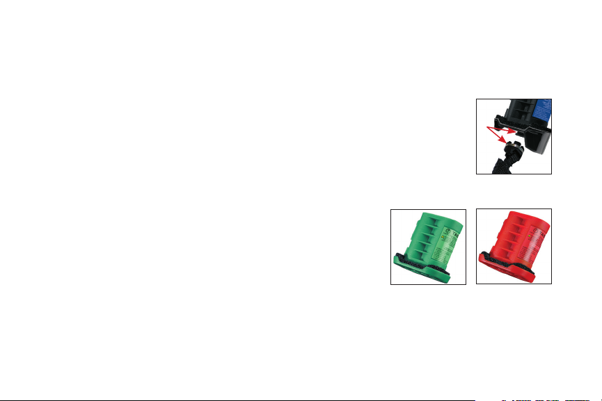
3. Remove the DPM from the X26 device (Figure 5).
4. Insert the green CCDPM into the X26 device. Verify that the DPM release
button (Figure 5) pops out from the recessed position with an audible click
(failure to do so could result in a damaged X26 device or a loss of power
during conguration).
5. If your X26 device has version 21 software or greater, a “P” is displayed on the
device’s Central Information Display (CID) for about six seconds, indicating that
the conguration code is being programmed into the device (Figure 6).
If your X26 device is programmed with version 20 or earlier, this process will
take about 14 seconds. When programming is complete, a two digit CCDPM
version level is displayed, and then the CID display will turn o.
Figure 5
Note: If the CID displays a “P”, then the error code “EO”, the X26 device is a citizen
model (X26C). In this instance, insert a standard DPM programmed with version 22
or higher into the device in order to recover it.
TASER® CDPM Operating Manual • MMU0014 Rev: B
Figure 6
7
Page 8

6. Place the safety switch in the up (ARMED) position. The CID blinks a two-digit number. The left-
side digit identies the index of the 5-digit code (“1” represents the rst digit of the code, “2” the
second digit, etc). The right-side digit represents your programmed number for the activation.
When no code has been entered, the right-side digit is zero, see below:
In the example below, the code “2-4-6-8-9” has been set. “2” is the rst number of the code, “4”
is the second, “6” is the third, and so on. The highlighted numbers below represent the
programmed activation code.
TASER® CDPM Operating Manual • MMU0014 Rev: B
8
Page 9

7. Decide what 5-digit number you want to use for your activation
code. Only digits 1 through 9 are valid for the activation code.
Illumination Selector
You cannot select the number 0. Also, it is not advised to use
1-1-1-1-1 as an activation code due to its simplicity to decipher.
8. Press the Illumination Selector (seen in Figure 7) repeatedly until
the desired number for the specied activation code digit is
displayed on the right side of the CID.
Figure 7
Note: Using pens or paper clips to press the Illumination Selector switch may damage it.
Pull the trigger switch once. The system will select that number and advance to
the next number in the 5-digit code. A number “2” should then display on the
left side of the CID (as seen in Figure 8).
Figure 8
TASER® CDPM Operating Manual • MMU0014 Rev: B
9
Page 10

9. Next, select the second number of the 5-digit code.
9.a. Press the Illumination Selector until the desired number for the second
activation code digit is displayed on the right side of the CID.
9.b. Pull the trigger switch. The system will enter that number. A number “3”
should then display on the left side of the CID (as seen in Figure 9).
9.c. Press the Illumination Selector until the desired number for the third
activation code digit is displayed on the right side of the CID.
9.d. Pull the trigger switch. The system will select that number.
A number “4” should then display on the left side of the CID
(as seen in Figure 10).
9.e. Press the Illumination Selector until the desired number for the
fourth activation code digit is displayed on the right side of the CID.
TASER® CDPM Operating Manual • MMU0014 Rev: B
10
Figure 9
Figure 10
Page 11

9.f. Pull the trigger switch. The system will select that number.
A number “5” should then display on the left side of the CID (as seen in
Figure 11).
9.g. Press the Illumination Selector until the desired number
for the fth activation code digit is displayed on the right
side of the CID.
9.h. Pull the trigger switch. The system will select that number.
9.i. The CID will display the CCDPM battery’s capacity for approximately
six seconds and then will display the letters “CC” to indicate that the
correctional mode has been fully congured (see Figure 12).
Note: Wait until the letters “CC” are displayed before placing the safety switch to the
down (SAFE) position.
Figure 11
Figure 12
TASER® CDPM Operating Manual • MMU0014 Rev: B
11
Page 12

10. Place the safety switch in the down (SAFE) position.
Note: It is advisable to conrm proper numeric entry of the 5-digit activation code at this time. To do
so, cycle the safety switch back to the up (ARMED) position and cycle through the entered activation
code via the trigger switch to verify code entry. The X26 device will not spark or deploy if either the
green CCDPM or red DCDPM is inserted. Do not attempt to check the activation code when a CDPM
or DPM/XDPM™ is inserted in the device, the trigger activation will deploy the X26 device.
11. Remove the green CCDPM and insert the CDPM with the lanyard/wrist strap attached.
Note: If the lanyard/wrist strap is disconnected for an extended period of time from the CDPM
(approximately 24 hours) while the CDPM is inserted in an X26 device, a “brown out” condition may
occur. A “brown out” condition will reset the internal clock of the X26 device to “0” thereby preventing
accurate accountability of device use. The “brown out” condition will be rectied the next time the
device information is downloaded via the dataport software but the informational time stamps will
not be accurate for those uses which occurred after the “brown out” condition occurred. TASER
recommends that the lanyard/wrist strap stay attached to the CDPM at all times when the
CDPM is both in and out of the X26 device.
TASER® CDPM Operating Manual • MMU0014 Rev: B
12
Page 13

Verify that the DPM release button pops out from the recess position with an audible click.
The CID will display a “P” for about 6 seconds, indicating that the software version is being
programmed into the device. If a “P” is not displayed, contact TASER Customer Service
at 1-800-978-2737 or visit www.TASER.com.
Note: If for some reason you rst insert a standard DPM instead of a CDPM into the
device at this point in the conguration process, make sure the DPM is of version
22 or greater. If a lower-version DPM is installed, the error “E1” will display on the
CID. If this happens, remove the older DPM and install a version 22 or greater DPM
or a CDPM. The CID will display a “P” for about 6 seconds, and the device will be
congured to use the CDPM.
Figure 13
12. Place the safety switch in the up (ARMED) position.
The CID will display a blinking “AC” (Figure 13).
• IftheCIDdisplays“EE”or“E1”(asshownin
Figures 14 and 15) contact TASER Customer Service
at 1-800-978-2737 or visit www.TASER.com.
Figure 14
Figure 15
TASER® CDPM Operating Manual • MMU0014 Rev: B
13
Page 14

13. Enter the 5-digit activation code. Use the same process as steps 8–9.h.
• Anon-blinking“AC”ontheLEDdisplayindicatesthatthe
5-digit activation code has been accepted and validated
(Figure 16). Go to step 14.
• Anon-blinking“AF”ontheLEDdisplayindicatesthat
the activation code entered is not correct (Figure 17).
If this occurs, repeat steps 8-9.h to re-enter the activation code.
14. Place the safety switch in the down (SAFE) position. The X26 device is now
congured and ready for use when the safety switch is placed in the up (ARMED)
position.
Figure 16
Note: By simply installing a CDPM without rst conguring the device with the
green CCDPM, the lanyard/wrist strap will still act to disable the X26 device; however,
the security code feature will not be enabled. In this case, by simply reattaching the
lanyard/wrist strap, the X26 device will be fully operational again without the
required 5-digit activation code.
TASER® CDPM Operating Manual • MMU0014 Rev: B
14
Figure 17
Page 15

Note: With a CCDPM-congured device, each occurrence of either the CDPM being removed from
the device or the lanyard/wrist strap becoming disconnected from an installed CDPM for two seconds
or more, will require the re-entry of the 5-digit activation code to make the X26 device operational
again.
RE-ENTERING THE ACTIVATION CODE
1. Verify that the TASER cartridge is removed. Failure to remove the TASER cartridge prior to
re-entering the activation code could cause serious injury.
2. Place the safety switch in the up (ARMED) position. The CID displays a blinking “AC” prompting
for the 5-digit activation code.
3. Refer to steps 8-9.h. under “CONFIGURING A TASER X26 DEVICE FOR THE CDPM.”
CHANGING THE ACTIVATION CODE
If it becomes necessary to change a device’s activation code, perform the “CONFIGURING A TASER X26
DEVICE FOR THE CDPM” instructions.
TASER® CDPM Operating Manual • MMU0014 Rev: B
15
Page 16

DE-CONFIGURING A TASER X26 DEVICE
1. Verify that the TASER cartridge is removed. Failure to remove the TASER
cartridge prior to de-conguration could cause serious injury.
2. Verify that the safety switch is in the down (SAFE) position.
3. Remove the CDPM from the X26 device.
4. Insert the red DCDPM into the X26 device.
5. A “P” is displayed on the X26 device CID for about 6 seconds, indicating
Figure 18
that the conguration code is being de-programmed from the device.
When deprogramming is complete, a two-digit DCDPM revision level is displayed.
6. Place the safety switch in the up (ARMED) position. The CID will display battery capacity
followed by display of “Cd” indicating that de-conguration has completed (see Figure 18).
7. Once “Cd” has been displayed, place the safety switch in the down (SAFE) position.
8. Remove the red DCDPM from the X26 device.
TASER® CDPM Operating Manual • MMU0014 Rev: B
16
Page 17

9. Insert a standard DPM, software revision 22 or greater, in the X26 device. Verify that the
DPM release button pops out from the recess position with an audible click.
Note: You can use the CDPM instead of a standard DPM. In this instance, the X26 device will be
programmed to revision 22 or greater. Additionally, if you use the CDPM after the device has been decongured, the lanyard/wrist strap will still act to disable the X26 device; however, the security code
feature will not be enabled. In this case, by simply reattaching the lanyard/wrist strap, the X26 device
will be fully operational again without the required 5-digit activation code.
10. A “P” is displayed on the X26 device CID for about 6 seconds, indicating that the X26 device
operational code is being programmed into the device. When programming is complete, the
DPM insertion boot up sequence will display.
TASER® CDPM Operating Manual • MMU0014 Rev: B
17
Page 18

Note: If a “P” is not displayed, the DPM is invalid or the revision level is under 22. Using a CDPM as
described in the note for step 9 above can avoid this. If the “P” is not displayed, remove the DPM and
repeat step 9 with a CDPM or use a DPM with a revision of 22 or higher.
11. At the conclusion of the boot up sequence, the de-conguration is complete. The device
is now a standard X26 device, ready for use when the safety switch is placed in the up (ARMED)
position.
TASER® CDPM Operating Manual • MMU0014 Rev: B
18
Page 19

CID DISPLAY EXPLANATIONS
EO: This error code is displayed when you attempt to load the Conguration CDPM (CCDPM) into
the TASER X26 device Citizen model (X26C).
E1: This error code is displayed if a Version 21 or earlier DPM is inserted in an X26 Device
after it has been congured/de-congured with the CCDPM/DCDPM without rst having
nished the conguration/de-conguration process by inserting a version 22 DPM for
software programming. This error may be xed by simply inserting a version 22 or greater
DPM/CDPM into the X26 device for the completion of the conguration process.
EE: This error code is displayed when an internal error is detected. This may be caused by either
problems within the CDPM or the X26 device. Call TASER customer service at 1-800-978-2737.
AC: Blinking indicates that an activation code is required for entry in order for a CDPM
congured X26 device to operate. Non Blinking indicates that the 5-digit activation code
has been accepted and validated.
TASER® CDPM Operating Manual • MMU0014 Rev: B
19
Page 20

AF: This indicates that the activation code entered is not correct. Cycle the safety to reattempt
activation code entry with proper code number sequence.
CC: This indicates that the X26 device is Control Congured with a 5-digit activation code. It is
necessary to then insert a version 22 or greater DPM to complete the conguration process.
Cd: This indicates that the X26 device has been de-congured with the DCDPM. It is necessary to
then insert a version 22 or greater DPM to complete the de-conguration process.
See www.TASER.com for warranty information on this product.
TASER® CDPM Operating Manual • MMU0014 Rev: B
20
Page 21

Page 22

CUSTOMER SERVICE:
U.S.: 1.800.978.2737 or 1.480.905.2000
International: +1.800.978.2737 or +1.480.905.2000
www.TASER.com
CCDPM, CDPM, DCDPM, DPM, X26, X26C, XDPM, and ©™ is a trademark of TASER International, Inc., and
TASER® is a registered trademark of TASER International, Inc., registered in the U.S. All rights reserved.
© 2009 TASER International, Inc.
 Loading...