

Page 1
PUSH
»
X-17
Professional DJ Mixer
OWNER’S MANUAL/ MODE D’EMPLOI / BEDIENUNGSANLEITUNG /
MANUALE D'ISTRUZIONI / Mezclador de DJ profesional
D00676200A
Page 2

2 TASCAM X-17
English Important Safety Precautions
IMPORTANT (for U.K. Customers)
DO NOT cut off the mains plug from this
equipment. If the plug fitted is not suitable for the power
points in your home or the cable is too short to reach a power
point, then obtain an appropriate safety approved extension lead
or consult your dealer.
If nonetheless the mains plug is cut off, remove
the fuse and dispose of the plug
immediately,
to avoid a possible shock hazard by inadvertent connection to
the mains supply.
If this product is not provided with a mains plug, or one has to
be fitted, then follow the instructions given below:
IMPORTANT. DO NOT make any connection to the larger
terminal which is marked with the letter E or by the safety earth
symbol ççor coloured GREEN or GREEN-and-YELLOW.
The wires in the mains lead on this product are coloured in
accordance with the following code:
BLUE : NEUTRAL
BROWN : LIVE
As these colours may not correspond with the coloured
markings identifying the terminals in your plug proceed as
follows:
The wire which is coloured BLUE must be connected to the
terminal which is marked with the letter N or coloured BLACK.
The wire which is coloured BROWN must be connected to the
terminal which is marked with the letter L or coloured RED.
When replacing the fuse only a correctly rated approved type
should be used and be sure to re-fit the fuse cover.
IF IN DOUBT — CONSULT A COMPETENT
ELECTRICIAN.
TO THE USER
This equipment has been tested and found to
comply with the limits for a Class A digital device,
pursuant to Part 15 of the FCC Rules. These limits
are designed to provide reasonable protection
against harmful interference when the equipment
is operated in a commercial environment. This
equipment generates, uses, and can radiate radio
frequency energy and, if not installed and used in
accordance with the instruction manual, may
cause harmful interference to radio
communications.
Operation of this equipment in a residental area is
likely to cause harmful interference in which case
the user will be required to correct the
interference at his own expense.
CAUTION
Changes or modifications to this equipment not
expressly approved by TEAC CORPORATION for
compliance could void the user's authority to
operate this equipment.
For U.S.A
TASCAM X-17 51
Block diagram / Schéma synoptique / Blockschaltbild / Schema a blocchi / Diagrama de bloques
Block diagram / Schéma synoptique / Blockschaltbild /
Schema a blocchi / Diagrama de bloques
For the consumers in Europe
WARNING
This is a Class A product. In a domestic environment, this
product may cause radio interference in which case the user
may be required to take adequate measures.
Pour les utilisateurs en Europe
AVERTISSEMENT
Il s’agit d’un produit de Classe A. Dans un environnement
domestique, cet appareil peut provoquer des interférences
radio, dans ce cas l’utilisateur peut être amené à prendre
des mesures appropriées.
Für Kunden in Europa
Warnung
Dies is eine Einrichtung, welche die Funk-Entstörung nach
Klasse A besitzt. Diese Einrichtung kann im Wohnbereich
Funkstörungen versursachen ; in diesem Fall kann vom
Betrieber verlang werden, angemessene Maßnahmen
durchzuführen und dafür aufzukommen.
Page 3
IMPORTANT SAFETY INSTRUCTIONS English
1) Read these instructions.
2) Keep these instructions.
3) Heed all warnings.
4) Follow all instructions.
5) Do not use this apparatus near water.
6) Clean only with dry cloth.
7) Do not block any ventilation openings. Install in accordance
with the manufacturer's instructions.
8) Do not install near any heat sources such as radiators, heat
registers, stoves, or other apparatus (including amplifiers) that
produce heat.
9) Do not defeat the safety purpose of the polarized or
grounding-type plug. A polarized plug has two blades with one
wider than the other. A grounding type plug has two blades and
a third grounding prong. The wide blade or the third prong are
provided for your safety. If the provided plug does not fit into
your outlet, consult an electrician for replacement of the obsolete
outlet.
10)Protect the power cord from being walked on or pinched
particularly at plugs, convenience receptacles, and the point
where they exit from the apparatus.
11)Only use attachments/accessories specified by the
manufacturer.
12)Use only with the cart, stand, tripod, bracket, or table
specified by the manufacturer, or sold with the apparatus. When
a cart is used, use caution when moving the cart/apparatus
combination to avoid injury from tip-over.
• Do not expose this apparatus to drips or splashes.
• Do not place any objects filled with liquids, such as vases, on
the apparatus.
• Do not install this apparatus in a confined space such as a
book case or similar unit.
• The apparatus draws nominal non-operating power from the
AC outlet with its POWER switch in the off position.
13) Unplug this apparatus during lightning storms or when
unused for long periods of time.
14) Refer all servicing to qualified service personnel. Servicing is
required when the apparatus has been damaged in any way,
such as power-supply cord or plug is damaged, liquid has been
spilled or objects have fallen into the apparatus, the apparatus
has been exposed to rain or moisture, does not operate
normally, or has been dropped.
TASCAM X-17 3
Page 4
English Introduction
Table of contents
Introduction ................................................................... 4
Some notes and precautions.................................... 4
Serial number, etc.................................................... 4
Rack-mounting the unit........................................... 4
Features and controls..................................................... 5
Top panel................................................................. 6
How to replace the fader ......................................... 8
Rear panel................................................................ 8
Sampler ................................................................... 9
Specifications............................................................... 11
Block diagram.............................................................. 51
Introduction
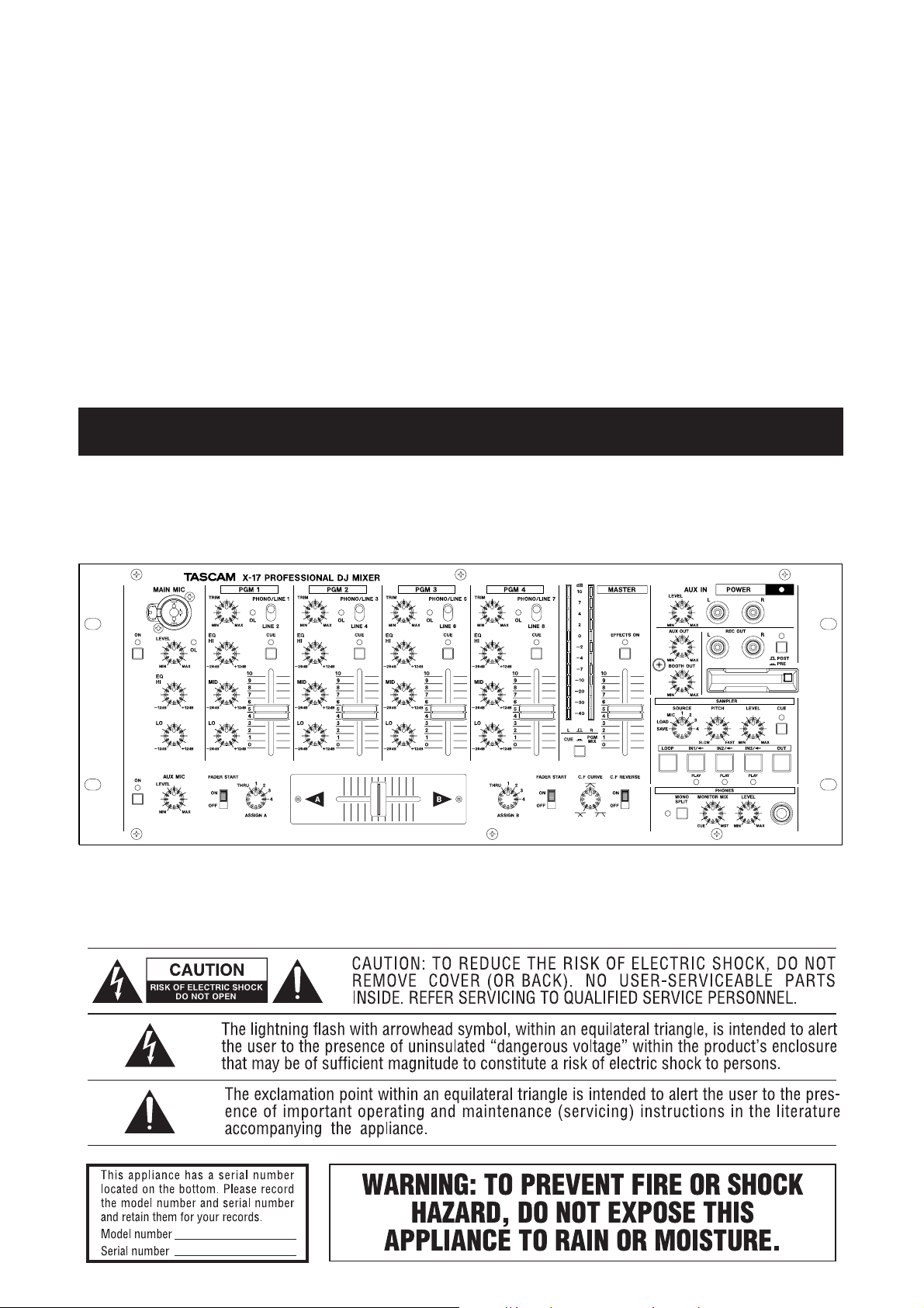
The X-17 is a sophisticated 4–PGM DJ mixer which
allows you to connect many devices, and mix in a
creative way. With a sophisticated layout, the X-17
combines easy operation with a wide range of functions.
It is VERY IMPORTANT that you read this manual
before connecting and using the mixer, in order get the
best out of it.
We recommend contacting our authorized Technical
Service department, or that of your TASCAM dealer or
distributor if any maintenance or repair work is
necessary, so that you can continue to enjoy the best
possible performance and operation.
Only use the AC adaptor provided with the X-17, and do
not use the adaptor with any other equipment. Always
make sure that the voltage supplied to the adaptor
matches the input voltage as specified on the adaptor. In
case of doubt, consult a qualified electrician.
To avoid hum in the audio, make sure that the power
cable is far away from the signal cables.
NOTE
When transporting the unit, always use the original
packing materials or a properly-designed equipment
case. For this reason, we strongly recommend that
you save all the packing materials that came with
the X-17, in case you need to transport it in the
future.
Connections to other equipment
It is extremely important that the power is turned off on
all units when making or breaking connections to or from
the X-17.
When turning power on, it is usually a good idea to start
with the source (turntables, CD players, etc.), then the X17 and finish with the amplifier system.
Turning power off should be done in the other direction
(amplifiers first, then other equipment).
If you have to turn off the X-17 and turn it on again,
always wait for 3 or more seconds between turning the
unit off and on again.
Some notes and precautions
Treat the X-17 as you would any other piece of precision
equipment.
Avoid exposing it to extremes of temperature and
humidity and avoid mechanical shocks and vibration.
Keep the unit away from strong magnetic fields (TV sets,
computer monitors, large electric motors, etc.).
Environmental considerations
The X-17 may be used in most areas, but to maintain top
performance, and prolong operating life, observe the
following environmental conditions:
The nominal temperature should be between 5°C and
35°C (41°F and 95°F).
Relative humidity should be 30 to 90 degrees noncondensing.
As the unit may become hot during operation, always
leave sufficient space above and around the unit for
ventilation.
Do not install this equipment in a confined space such as
a bookcase or similar unit.You should not place the unit
on a piece of equipment generating heat, an amplifier for
example, to avoid possible problems with overheating.
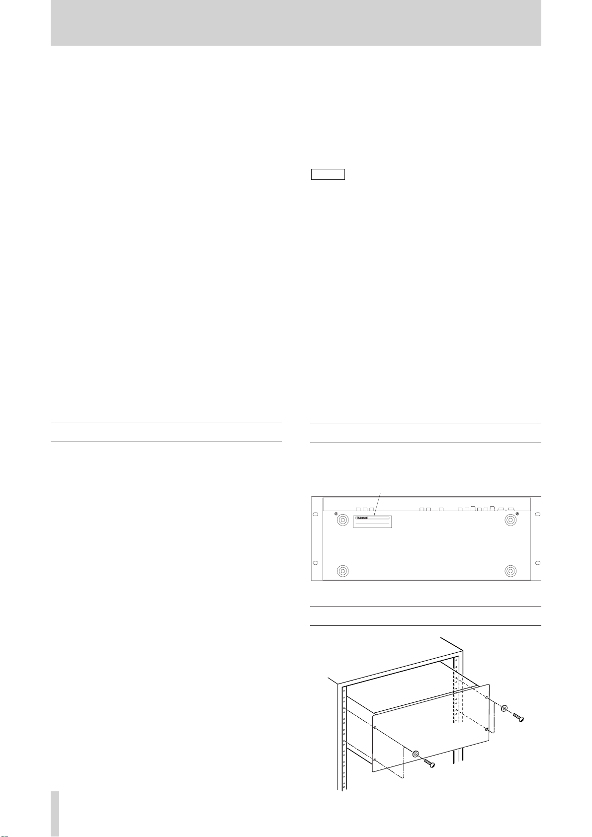
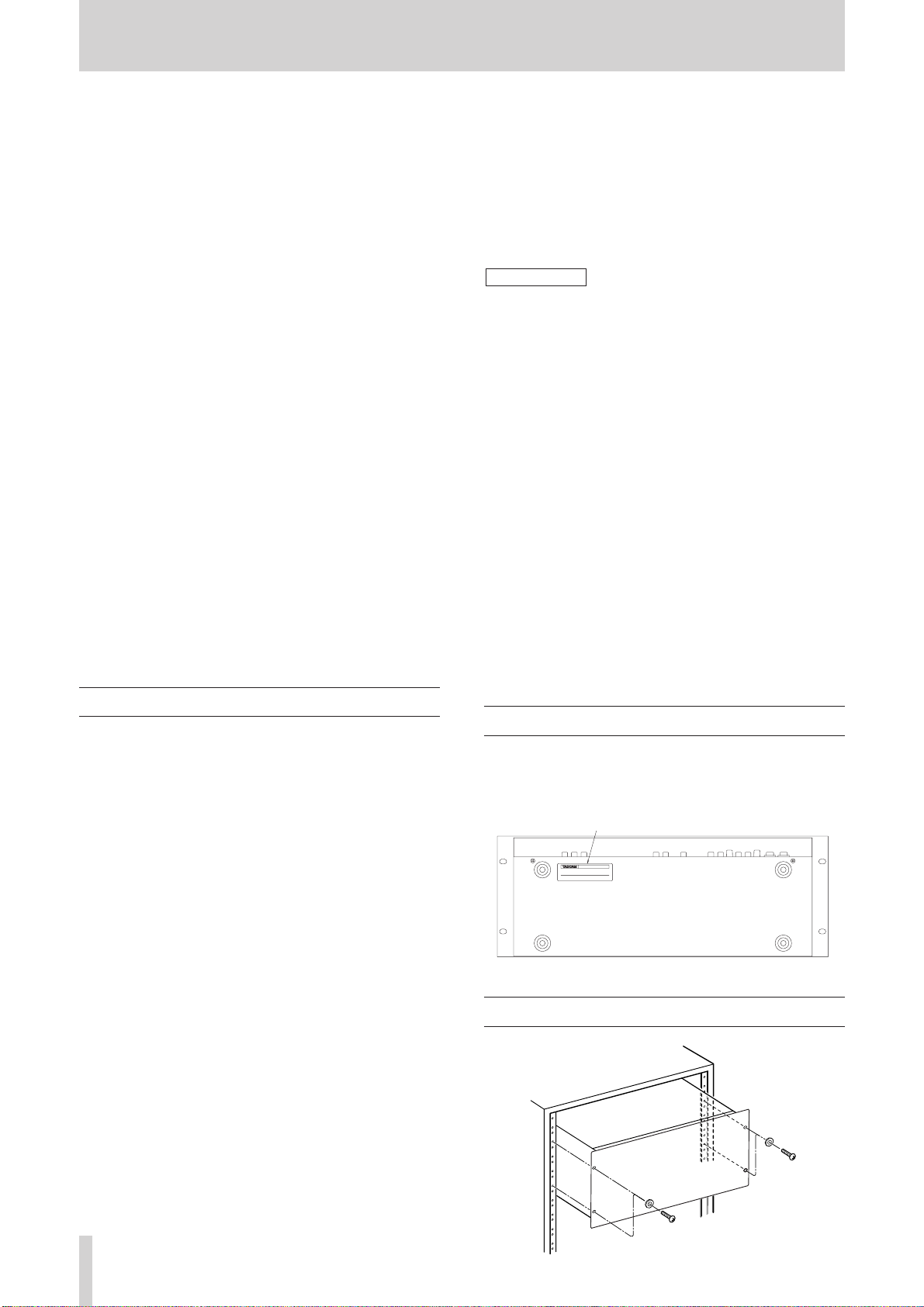
Serial number, etc.
The serial number of the X-17 is located on a sticker at
the rear of the unit on the bottom panel. Make a note of
this for future reference (warranty, etc.).
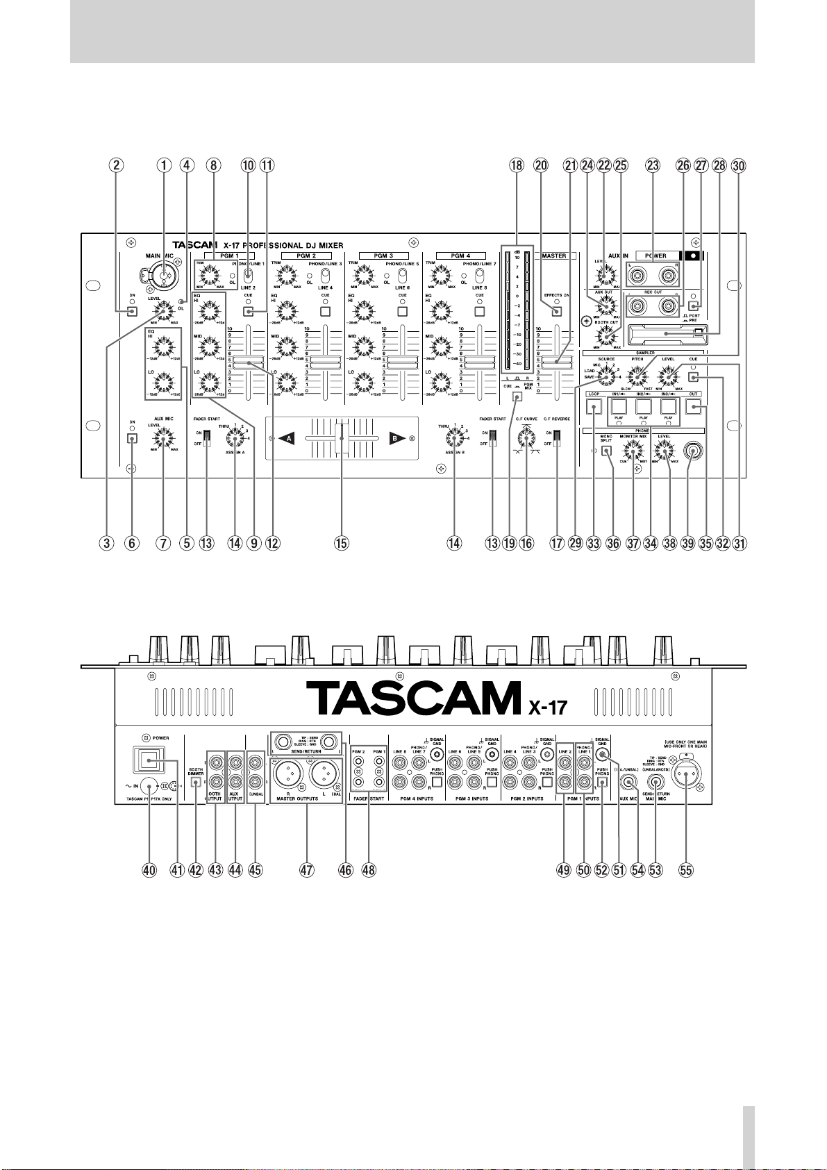
Rack-mounting the unit
4 TASCAM X-17
Page 5
Features and controls English
PUSH
Features and controls
TASCAM X-17 5
Page 6

English Features and controls
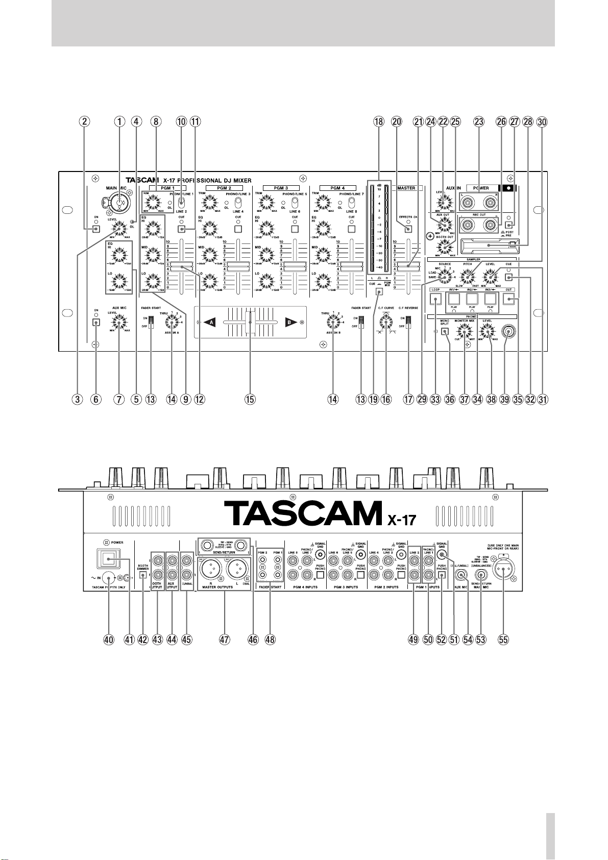
Top Panel
1 MAIN MIC input
Connect the main microphone to this XLR/TRS
connector that can accept both balanced and unbalanced
signals.
This is a “combo” type jack which accepts both XLR
type and 1/4” TRS type connectors.
Connections are as follows:
XLR TRS
GND: Pin 1 Sleeve
HOT: Pin 2 Tip
COLD: Pin 3 Ring
NOTE
There is another MAIN MIC input connector on the
rear panel. Only use either the connector on the
rear panel or the top panel (you cannot use both at
the same time).
The MAIN MIC channel also has a dedicated insert jack
on the rear panel.
2 ON switch and indicator for MAIN MIC
channel
Push for on, and push again for off. When this switch is
on, the MAIN MIC channel is active and the indicator
lights.
3 MAIN MIC LEVEL
Adjusts the signal level of both the top and rear MAIN
MIC inputs.
7 AUX MIC LEVEL
Adjusts the signal level of the AUX MIC input.
8 TRIM controls and OL indicators
Adjust the input signal level for each PGM.
If a PGM’s input signal causes an overload, the PGM’s
OL indicator lights.
NOTE
All input sensitivity adjustments must be done very
carefully. Use the level meter and/or headphones
for reference. Make sure that the top red meter
LEDs do not all light up, as this shows that the
signal can clip (overload and distort).
9 PGM EQ
Provides three-band EQ (equalization) for each PGM
signal. The control for each band can cut the band by up
to 26 dB and boost it by up to 12 dB.
If all EQ controls on a PGM are set to –26dB, this will
almost completely cut the signal of the PGM.
0 Input Selector switches
Select the input signal for each PGM. Each PGM can
select from either a LINE input or a PHONO/LINE input
(the selection between phono and line is made on the rear
panel).
q CUE switches and indicators
Sends the pre-fader signals of the PGMs to the CUE
monitor bus. When CUE is activated for a PGM, the
CUE indicator lights.
4 OL indicator
When the MAIN MIC and/or AUX MIC input signal
cause an overload, this indicator lights (post-insert, but
pre-EQ).
NOTE
All input adjustments must be done very carefully.
Use the level meters and/or headphones for
reference. Make sure that the top red meter LEDs
do not all light up, as this shows that the signal can
clip (overload and distort).
5 MIC EQ
2-band EQ (HI and LO, both cutting and boosting by 12
dB) affecting both the the MAIN MIC and AUX MIC
input signals.
6 ON switch and indicator for AUX MIC channel
Push for on, and push again for off. When this switch is
on, the AUX MIC (auxiliary microphone) channel is
active and the indicator lights.
w PGM faders
Adjust the level of the PGMs
e FADER START switches
Set the automatic start of A and B using the cross-fader
on or off.
r Cross-fader ASSIGN selectors
Select the signal sources assigned to the A and B crossfader outputs. Each of the four PGMs can be selected as a
signal source, and there is also a THRU setting, which
means that no PGM is assigned to the cross-fader on that
side. Use the PGM and MASTER faders to adjust the
output if this setting is made.
t Cross-fader
Mixes between the A and B outs, assigned from the PGM
signals.
The cross-fader can be reversed, and you can set the
cross-fader curve to match your preferences (see below).
It is possible for you to replace the cross-fader if this
becomes necessary (see below for details).
6 TASCAM X-17
Page 7

Features and controls English
y C.F CURVE
Allows you to adjust the cross-fader response curve from
soft (counter-clockwise) to hard (clockwise).
u C.F REVERSE
Sets the direction of the cross-fader.
When in the OFF, position, moving the cross-fader
toward A increases the volume of the A signal and
moving the cross-fader toward B increases the volume of
the B signal. The ON setting reverses this
i Meters
This pair of peak meters indicates either the post-fader
(PGM or MASTER) MASTER signal level in stereo, or
the mono CUE signal levels.
o Meter selection switch (L/R –CUE/PROG)
Switches the meter indication between the MASTER
program (the switch is up) and the CUE signals (the
switch is depressed).
p EFFECTS ON switch and indicator
When this switch is on, the indicator lights, and the
master external effect loop is active.
a MASTER fader
Adjusts the level of the signal from the MASTER
OUTPUT jacks (both the balanced XLR and the
unbalanced RCA connectors).
s AUX IN LEVEL
Adjusts the level of the signals from the AUX IN jacks.
d AUX IN
Use these unbalanced RCA connectors to connect line
level equipment, such as CD players, cassette decks,
DAT decks, MD players, or another X-17, etc. This input
signal is input immediately pre-MASTER fader.
f AUX OUT LEVEL
Adjusts the signal level output from the AUX OUTPUT
jacks.
g BOOTH OUT LEVEL
Adjusts the signal level output from the BOOTH
OUTPUT jacks.
h REC OUTPUT
These unbalanced RCA jacks output the pre-MASTER
fader signal. This can be useful for a number of purposes:
for example, you could connect a recorder to these jacks,
and record your live performance without the MASTER
level affecting the recording.
j PRE/POST insert switch for REC OUT
This switch controls what is output from the REC OUT
jacks. When this switch is in the PRE setting (the switch
is depressed):
The four PGM signals and the sampler signal,
without the master insert loop.
In the POST setting:
The four PGM signals and the sampler signal,
with the master insert loop, the AUX IN signal,
and both the MAIN and AUX MIC signals.
k CompactFlash
This slot holds a CompactFlash card which you can use
to save sampled sounds from the X-17’s internal memory,
and to load them into the X-17’s internal memory. This
allows you to carry your favorite samples in a compact,
robust format.
The card can only be inserted in one direction. Press the
eject button to the right of the slot to eject the card.
Cover this slot using the attached protective cover when it
is not in use.
See the section on the sampler below for full details of
how to use the card and the sampler.
CompactFlash is a trademark of the CompactFlash
Association.
TM
card slot
l SAMPLER SOURCE selector
SAVE: Saves the X-17’s internal sample data to the
CompactFlash card.
LOAD: Loads sample data from the CompactFlash card
into the X-17’s internal memory.
MIC, 1-4: Select the sampling source (the MIC inputs or
any of the 4 PGMs).
; SAMPLER PITCH
Adjusts the sampler’s playback pitch and speed from half
speed (SLOW) to double speed (FAST).
z SAMPLER LEVEL
Adjusts the output level of the sampler signal.
x SAMPLER CUE switch and indicator
Sends the sampler pre-LEVEL signal to the CUE monitor
(the indicator lights when this is activate).
c SAMPLER LOOP key and indicator
Toggles sampler loop play on and off (the indicator lights
when sampler loop play is active).
v IN/<- keys (IN1, IN2, IN3)
Start sample recording or playback. When the SAMPLER
SOURCE selector is set to LOAD, these keys load
sample data from the CompactFlash card.
TASCAM X-17 7
Page 8

English Features and controls
b OUT key
Stops sample recording or playback. When the
SAMPLER SOURCE selector is set to SAVE, this key
saves the X-17’s internal sample data to the
CompactFlash card.
n MONO SPLIT switch and indicator
Selects headphone monitoring mode: either MONO
SPLIT mode (the indicator is lit) or STEREO mode (the
indicator is unlit).
STEREO mode: You monitor the CUE signal and
MASTER signal as determined by the PAN
control.
MONO SPLIT: You monitor the CUE signals in
mono from the left headphone, and the
MASTER signal in mono from the right
headphone.
m Monitor MIX
Adjusts the balance in the headphones between the CUE
signal and the MASTER signal.
, PHONES LEVEL
Adjusts level of the signals output through the
headphones.
. PHONES
Connect a standard pair of stereo headphones to this 1/4”
jack.
Rear Panel
/ AC Adaptor in
Use this jack to connect the PS-P17X AC adapter which
comes with your X-17.
Insert the plug following the arrow position of the AC
adapter plug, and the white dot on the rear panel.
WARNING
DO NOT use any adapter with the X-17 except the
PS-P17X adapter supplied with the X-17.
Connect the AC adapter jack to the X-17 in the way
shown on the illustration on the rear panel of the
X-17. If you connect the AC adapter in any other
way, you may damage the X-17.
! POWER switch
@ BOOTH DIMMER switch
When this switch is on, and when the MAIN MIC ON
switch is pressed, the level of the signal from the BOOTH
OUTPUT jacks is reduced by 20dB.
# BOOTH OUTPUT
These unbalanced RCA connectors output the preMASTER fader signal, whose level is adjusted using the
BOOTH OUT control.
Use the BOOTH DIMMER switch to reduce the level of
this signal.
How to replace the cross-fader
1. Move the fader to the top and remove the fader knob.
2. Remove the two screws retaining the fader.
3. Remove the fader.
4. Unplug the multiway connector connecting the X-17
to the fader.
5. Replace the fader with a new one, and connect the
multiway connector to the new fader.
6. Secure the new fader with the screws removed in the
first step.
$ AUX OUTPUT
These unbalanced RCA connectors output the preMASTER fader signal, whose level is adjusted using the
AUX OUT control.
% MASTER OUTPUT (UNBAL)
These unbalanced RCA connectors output the master
output signals (post-MASTER fader).
^ SEND/RETURN
Use these 1/4” TRS connectors (unbalanced) to insert an
external effect in the MASTER OUTPUT signal path.
This includes the four PGMs and the sampler.
The connector is wired as follows.
GND: Sleeve
SEND: Tip
RETURN: Ring
& MASTER OUTPUT (BAL)
These balanced XLR connectors output the master output
signals (post-MASTER fader), wired as follows:
GND: Pin 1
HOT: Pin 2
COLD: Pin 3
8 TASCAM X-17
Page 9

Features and controls English
* FADER START connectors
Connect devices supporting the fader start operation to
these mini-jacks.
You can enable the cross-fader start function
independently for the A and B outputs.
Move the cross-fader to start and/or stop (back cue) the
PGM A or B source automatically.
NOTE
The fader start signal is output from the tip, and the
fader stop (back cue) signal is output from the
sleeve. The ground for these connections is
provided by the signal ground of the device to
which the fader start is made.
( LINE inputs
Use these unbalanced RCA jacks to connect line level
equipment, such as CD players, cassette decks, MD
decks, etc.
) PHONO/LINE inputs
When the appropriate PUSH PHONO switch is in the
PHONO position (pushed in), connect turntables
equipped with MM (moving magnet) cartridges to these
unbalanced RCA jacks. When the switch is in the LINE
position (out) connect line level equipment, such as CD
players, cassette decks, MD decks, etc.
Always use the supplied shorting RCA plugs in any
PHONO jacks where a turntable is not connected.
WARNING
When the PUSH PHONO switch is set to PHONO,
only connect turntables equipped with an MM
cartridge to these connectors. Do not connect such
turntables to any other connectors.
Q SIGNAL GND terminals
If the turntables you use are fitted with grounding wires,
connect them to these GND terminals to reduce noise and
hum.
E MAIN MIC SEND/RETURN
Use this TRS 1/4” jack (unbalanced) to inserts an external
effect in the MAIN MIC signal path.
The connections are follows:
GND: Sleeve
SEND: Tip
RETURN: Ring
R AUX MIC input
Connect an auxiliary microphone to this balanced TRS
connector, wired as follows:
GND: Sleeve
HOT: Tip
COLD: Ring
T MAIN MIC input
Connect the microphone to this balanced XLR connector,
wired as follows:
GND: Pin 1
HOT: Pin 2
COLD: Pin 3
NOTE
There is another MAIN MIC input connector on the
top panel. Only use either the connector on the rear
panel or the top panel (you cannot use both at the
same time).
Sampler
The X-17 includes three samplers, each of which can
record 30 seconds of sample data at 16-bit resolution.
These samples can be stored on and loaded from a CF
card (card formats other than CompactFlash do not work
with the X-17) of at least 16MB capacity.
NOTE
The X-17 uses TASCAM’s own sample data format.
You can only use an X-17 to load and save sample
data.
W PUSH PHONO switches
Push this switch in to use the odd-numbered (1, 3, 5 and
7) LINE/PHONO inputs with turntables. Leave it out to
use these inputs with other equipment (CD players, MD
decks, etc.).
WARNING
Turn the power OFF on all amplifier systems, etc.
when using these switches. When these switches
are pressed, loud noises are produced that may
damage hearing and equipment.
Sampling
You can record samples from PGMs 1 through 4 or from
the MIC signals. When making a sample, the sampling
point is at the pre-fader point of PGMs 1 through 4.
1. Use the SAMPLER SOURCE selector to select the
sampling source (PGM 1-4 or MIC).
2. To start sampling, press an unlit IN key (IN1, IN2 or
IN3). The unlit key shows that the sampler is empty.
Sampling starts, the IN key lights, and the OUT key
starts to flash.
TASCAM X-17 9
Page 10

English Features and controls
3. Stop recording by pressing the OUT key. If the
maximum recording time (30 seconds) is reached.
recording will stop automatically. The IN key you
pressed earlier, and the OUT key both light.
Erasing sample data
When a sampler contains data (its IN key is lit), press and
hold the OUT key and press the IN key to erase the
sample data. The IN key goes out. If no samplers contain
data, the OUT key goes out as well.
Playback
1. When a sampler contains data (its IN key is lit) press
its IN key to start playback. The appropriate PLAY
indicator lights and playback starts from the
beginning of the sample. Pressing any IN key again
during playback will start playback from the start of
the appropriate sample (including the currentlyplaying one).
NOTE
Note that the X-17 can hold three samples but only
one can be played at a time.
2. Use the LEVEL knob to adjust the output level.
3. Stop playback by pressing the OUT. The appropriate
PLAY indicator goes out.
Looped Playback
1. Press LOOP key to light it. When it is lit, pressing one
of the IN keys starts looped playback, and the
appropriate PLAY indicator lights.
2. When the LOOP key is lit, and looped playback is
going on, you can press LOOP to turn off the key and
stop the looping. This does not stop the playback,
though. Playback stops at the end of the sample (or
when you press the OUT key).
2. Set the SAMPLER SOURCE selector to the SAVE
position. The OUT key starts to flash.
3. Press the OUT key. It lights and the save operation
starts. If any data is already stored on the card, it is
deleted, and the save starts. As data is saved from
each sample, the IN key for that sample flashes.
4. After the last sample has been saved, the OUT key
flashes, and the IN keys return to the state they were
in before the save operation (lit keys indicate a sample
is present).
Loading samples from a CompactFlash card
NOTE
Note that this operation erases all samples currently
in the X-17’s memory. If there are any samples in
memory that you want to keep, you should save
them to another card first.
1. Insert the CompactFlash card into the slot.
2. Set the SAMPLER SOURCE SELECTOR to the
LOAD position. The IN1/<- key starts to flash.
3. Press the IN1/<- key. It flashes, and the load operation
starts.
4. After the load operation has finished and samples
have been loaded, the IN keys light (if one sample has
been loaded, IN1 lights, if two samples have been
loaded, IN1 and IN2 light, if three samples have been
loaded, all keys light. If there were no samples to be
loaded on the card, no keys are lit.
5. After the load operation is finished, the IN keys
corresponding to the loaded samples will light. If no
samples have been loaded from the card, no keys will
be lit.
Sampler pitch and tempo control
1. Use the PITCH control to adjust the playback pitch
and speed. The pitch range is from half speed
(SLOW) to double speed (FAST).
Saving samples to a CompactFlash card
Note that when you turn off the X-17, all sample data not
saved on cards is lost. Save samples to a CompactFlash
card using the procedure described here.
1. Insert the Compact Flash card into the slot.
NOTE
Note that this operation erases all data on the card.
If there is any data you want to keep on a card, you
should not save to that card.
10 TASCAM X-17
Page 11
Specifications English
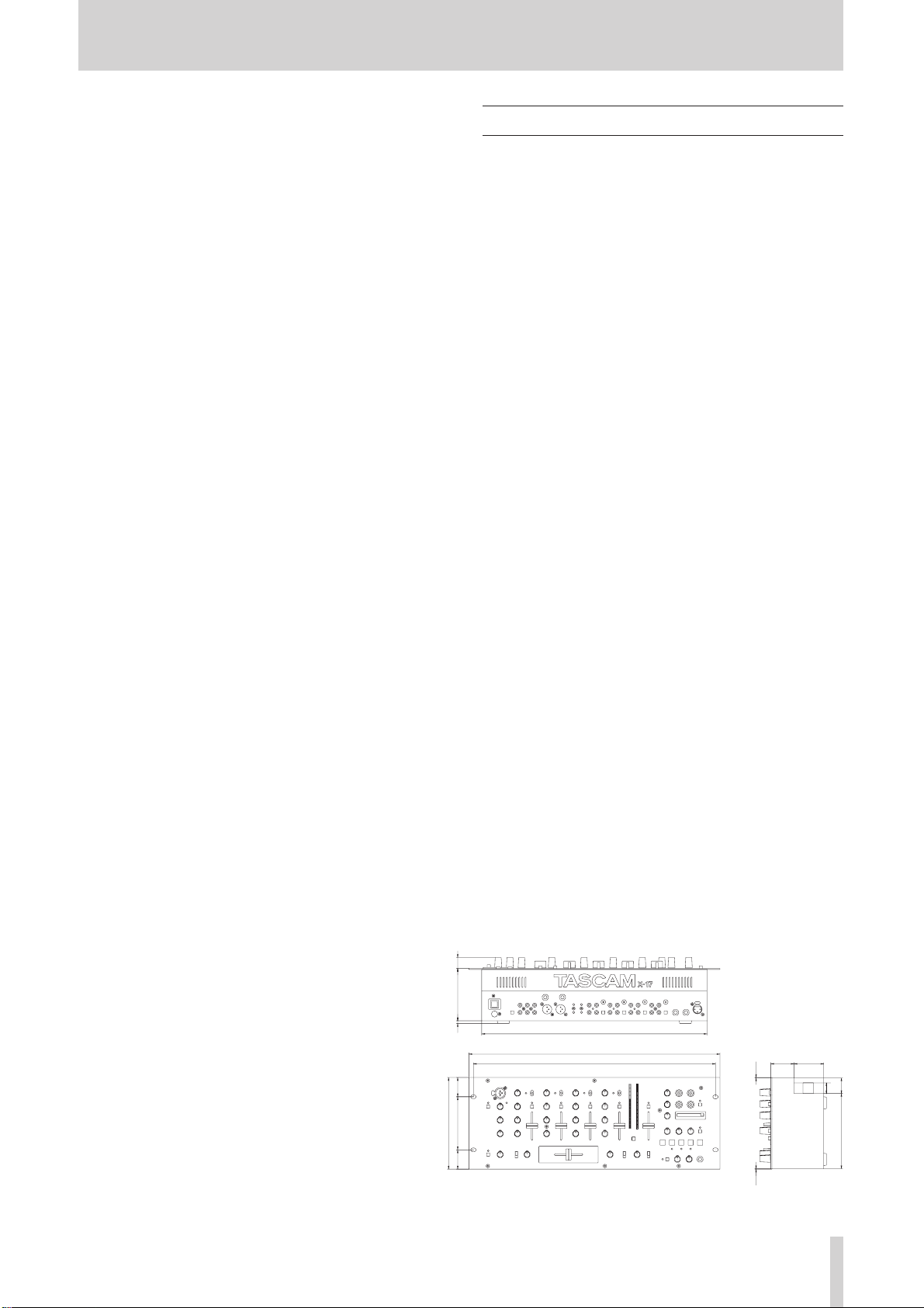
(1) (3.4)
(58)43.6
(20)1025
176
102 (37)(37)
435
482
465
(28.6)
(20)
143
Specifications
LINE IN (PGM1-4):
RCA, unbalanced
Input level: –10 dBV
Input impedance: 10 kΩ
PHONO/LINE inputs (PGM1-4)
RCA, unbalanced
PHONO position
Input level: –54 dBV
Input impedance: 47 kΩ
RIAA equalization
LINE position
Input level: –10 dBV
Input impedance: 10 kΩ
MAIN MIC input (on the top panel)
XLR/TRS, balanced/unbalanced
Input level: –50 dBV
Input impedance: 2.8 kΩ
MAIN MIC input (on the rear panel)
XLR, balanced
Input level: –50 dBV
Input impedance: 2.8 kΩ
AUX MIC input (on the rear panel)
TRS, balanced/unbalanced
Input level: –50 dBV
Input impedance: 2.8 kΩ
AUX IN (on the top panel)
Audio Performance
Frequency response:
LINE IN: 20 Hz to 20 kHz, +/–1.0 dB
PHONO IN: 30 Hz to 15 kHz, +/–2.0 dB
(RIAA)
MIC IN: 30 Hz to 18 kHz, +/–3.0 dB
Signal to nose ratio:
LINE IN: 78 dB (IHF A Weighting)
PHONO IN: 70 dB (IHF A Weighting)
MIC IN: 60 dB (IHF A Weighting)
Total harmonic distortion:
LINE IN: <0.1 %
PHONO IN: <0.2 %
MIC IN: <0.2 %
Crosstalk >60 dB (@1 kHz)
PGM EQ
HI: +12 dB to –26 dB
MID: +12 dB to –26 dB
LO: +12 dB to –26 dB
Filter (cut frequency at –6dB, slope 12dB/oct)
HI: 6.5 kHz
MID: 6.5 kHz & 200 Hz
LO: 200 Hz
MIC EQ
HI: 5.5 kHz, +12 dB to –12 dB
LO: 125 Hz, +12 dB to –12 dB
RCA, unbalanced
Input level: –10 dBV
Input impedance: 10 kΩ
MASTER OUTPUTS (BAL)
XLR, balanced
Nominal output level: +4 dBu
Output impedance: 75 Ω
MASTER OUTPUTS (UNBAL)
RCA, unbalanced
Nominal output level: 0 dBV
Output impedance: 100 Ω
BOOTH OUTPUT:
RCA, unbalanced
Power requirement: 120 V (60 Hz)
230 V (50Hz)
Power consumption: 27 W
Dimension (w x h x d): 482 x 176 x 102 (mm)
19 x 6.9 x 4 (in)
Weight: 4.3 kg, 9.48 lbs (main unit)
0.8 kg, 1.8 lbs (PS-P17X AC
adaptor)
Applicable electromagnetic environment:
E4
Peak inrush current: 1.6 A
Nominal output level: 0 dBV
Output impedance: 100 Ω
REC OUTPUT:
RCA, unbalanced
Nominal output level: –10 dBV
Supplied accessories
Shorting RCA plug for PHONO x 8
AC Adaptor (PS-P17X) x 1
Operation manual x 1
Output impedance: 100 Ω
AUX OUTPUT:
All specifications subject to change without notice.
RCA, unbalanced
Nominal output level: 0 dBV
Output impedance: 100 Ω
SEND/RETURN
TRS, unbalanced
Nominal output level(send): –4 dBV
Output impedance: 100 Ω
Input level(return): –4 dBV
Input impedance: 10 kΩ
MAIN MIC SEND/RETURN
TRS, unbalanced
Nominal output level(send): –4 dBV
Output impedance: 100 Ω
Input level(return): –4 dBV
Input impedance: 10 kΩ
PHONES:
100 mW + 100 mW, (at 33 Ω)
TASCAM X-17 11
Page 12

Français Consignes de sécurité importantes
IMPORTANT (pour le Royaume-Uni)
Ne modifiez pas le cordon d’alimentation de cet
appareil. Si la fiche qui le termine ne correspond pas aux
prises murales de votre domicile, ou si le câble est trop court
pour atteindre une de ces prises, procurez-vous une rallonge du
modèle approprié, conforme aux normes de sécurité, ou
consultez votre revendeur.
Si le cordon secteur vient à être coupé ou endommagé, retirez le
fusible de l’appareil puis débranchez immédiatement la prise,
afin d’éviter tout court-circuit ou électrocution suite à une mise
sous tension par inadvertance.
Si ce produit a été livré sans cordon secteur, ou avec un modèle
inapproprié,lisez les instructions ci-après et suivez-les
scrupuleusement :
IMPORTANT. N’EFFECTUEZ AUCUNE connexion au
niveau de la broche repérée par la lettre E ou par le symbole de
masse ç ou portant un fil de couleur VERTE ou VERT et
JAUNE.
Les couleurs du cordon secteur livré avec cet appareil respectent
le code suivant:
BLEU : NEUTRE
MARRON : PHASE
Comme ces couleurs ne correspondent pas forcément à celles
idientifiant les broches de votre prise secteur, procédez comme
suit :
Le fil BLEU doit être relié à la broche repérée par la lettre N ou
coloriée en NOIR.
Le fil MARRON doit être relié à la broche repérée par la lettre
L ou coloriée en ROUGE.
En cas de remplacement du fusible, n’utilisez qu’un fusible du
même calibre, et remettez bien en place son couvercle de
protection.
EN CAS DE DOUTE, ADRESSEZ-VOUS À UN
ÉLECTRICIEN COMPÉTENT.
12 TASCAM X-17
Page 13
CONSIGNES DE SÉCURITÉ IMPORTANTES Français
1) Lisez ces instructions.
2) Gardez ces instructions en lieu sûr, pour référence
ultérieure.
3)Tenez compte de tous les avertissements.
4) Suivez toutes les instructions.
5) N’utilisez pas cet appareil près de l’eau.
6) Ne nettoyez l’appareil qu’avec un chiffon sec.
7) N’obstruez pas les ouïes de ventilation. Installez
l’appareil conformément aux instructions du constructeur.
8) N’installez pas l’appareil à proximité de sources de
chaleur, telles que radiateur, four ou tout autre appareil
dissipant des calories (amplificateur de puissance, par
exemple).
9) Ne désactivez pas les dispositifs de sécurité
(détrompeurs) des prises polarisées ou avec mise à la
terre. Une prise polarisée possède un contact plus grand
que l’autre ; une prise avec mise à la terre possède une
troisième broche, prévue pour votre sécurité. Si la prise se
trouvant à l’extrémité du cordon secteur fourni avec votre
appareil ne correspond pas à votre prise murale, consultez
un électricien pour son remplacement.
10) Évitez de marcher sur le cordon secteur, de le coincer
ou de le pincer, ainsi que de couder le cordon au niveau
de l’appareil ou de la prise secteur.
11) N’utilisez que les dispositifs optionnels ou les
accessoires recommandés par le constructeur.
12) N’utilisez l’appareil qu’avec des supports ou
dispositifs de fixation fournis ou recommandés par le
constructeur.
• N’exposez pas l’appareil à des éclaboussures ou à des
gouttes d’eau.
• Ne posez pas d’objets contenant du liquide (vase, tasse,
cannette...) sur l’appareil.
• N’installez pas cet appareil dans un espace confiné,
dépourvu de ventilation , comme par exemple une
bibliothèque.
• Même si son interrupteur se trouve e n position OFF,
l’appareil consomme du courant électrique, par
l’intermédiaire de son adaptateur secteur.
13) Débranchez le cordon d’alimentation de l’appareil en
cas d’orage ou s’il doit rester inutilisé pendant une longue
période.
14) Pour toute maintenance, adressez-vous à des
techniciens professionnels qualifiés. Un retour en SAV
est indispensable dès que l’appareil a été endommagé
d’une façon ou d’une autre : cordon secteur ou
alimentation défaillante, pénétration de liquide ou
introduction d’objets dans l’appareil, exposition à la pluie
ou à l’humidité, et bien sûr dès qu’il ne fonctionne pas
normalement, suite à une chute ou à un choc par exemple.
TASCAM X-17 13
Page 14
Français Introduction
Sommaire
Introduction ................................................................. 14
Remarques et précautions ...................................... 14
Numéro de série, etc. ............................................. 14
Montage en rack de l'appareil ................................ 14
Fonctions et commandes ............................................. 15
Surface de contrôle ................................................ 16
Remplacement du crossfader ................................. 18
Panneau arrière....................................................... 18
Section Sampler ..................................................... 19
Caractéristiques ........................................................... 21
Synoptique....................................................................51
Introduction
La X-17 est une console DJ 4 voies sophistiquée,
permettant de brancher de nombreux appareils et de
réaliser des mixages créatifs. Son ergonomie sophistiquée
et très étudiée lui permet d’allier simplicité de
fonctionnement et étendue des fonctions.
Il est TRÈS IMPORTANT de lire ce manuel
attentivement et dans sa totalité avant tout branchement
pour exploiter au mieux les possibilités de la X-17.
Pour la maintenance ou la réparation de l’appareil, nous
vous conseillons vivement de contacter votre revendeur
ou distributeur TASCAM. Vous serez ainsi assuré du bon
fonctionnement et des meilleures performances de votre
X-17.
N’utilisez que l’adaptateur secteur livré avec la X-17, à
l’exclusion de tout autre. Vérifiez avant tout branchement
que la valeur de votre tension secteur correspond à celle
indiquée sur l’adaptateur. Au moindre doute, veuillez
consulter un électricien qualifié.
Pour éviter tout parasite dans le signal audio (ronflette ou
autre), veillez à éloigner le câble secteur ou l’adaptateur
des câbles transportant le signal.
REMARQUE
Pour transporter l’appareil, n’utilisez que son
emballage d’origine ou un conditionnement
approprié (flight-case ou assimilé). Nous vous
conseillons par conséquent de conserver
l’emballage d’origine de la X-17, pour tout transport
ultérieur.
Connexion aux autres appareils
Il est extrêmement important d’éteindre tous les autres
appareils de votre système avant d’effectuer des
branchements sur la X-17.
Pour mettre sous tension le système, il est conseillé de
respecter l’ordre suivant : d’abord les sources de signal
(platine tourne-disques, lecteurs de CD, etc.), puis la X17 et, en tout dernier, le système d’amplification.
Pour mettre le système hors tension, il faut adopter
l’ordre inverse (d’abord le système d’amplification, puis
les autres appareils).
Si vous êtes amené à éteindre puis rallumer la X-17,
attendez toujours 3 secondes au minimum entre
l’extinction et la remise sous tension.
Remarques et précautions
Traitez votre X-17 avec tout le soin souhaitable pour un
appareil de précision.
Évitez de l’exposer à des conditions extrêmes de
température et/ou d’humidité, et évitez de la soumettre à
des chocs ou des vibrations d’origine mécanique.
Éloignez l’appareil des champs magnétiques intenses
(tels que ceux générés par un téléviseur, un moniteur
d’ordinateur, un moteur électrique puissant, etc.).
Considérations environnementales
La X-17 peut être utilisée à peu près partout, mais pour
assurer des performances maximales et prolonger sa
durée de vie, nous vous conseillons de veiller aux points
suivants :
La température nominale de fonctionnement doit être
comprise entre 5 °C et 35 °C, avec un taux d’hygrométrie
relatif de 30 % à 90 %, sans condensation.
L’appareil subit un échauffement modéré en cours de
fonctionnement : nous vous conseillons par conséquent
de ménager un espace libre suffisant au-dessus et autour
de la X-17 pour assurer une bonne ventilation.
N’installez pas l’appareil dans un espace confiné, tel
qu’une bibliothèque ou un meuble comparable. Pour
éviter toute surchauffe, ne placez pas la X-17 au-dessus
d’un autre appareil générant de la chaleur – un
amplificateur de puissance par exemple.
Numéro de série, etc.
Le numéro de série de la X-17 se trouve sur une étiquette
adhésive placée sur le fond de l’appareil, vers l’arrière.
Notez-le en lieu sûr pour toute référence ultérieure (mise
en œuvre de la garantie, etc.).
Montage en rack de l’appareil
14 TASCAM X-17
Page 15
Fonctions et Commandes Français
PUSH
Fonctions et Commandes
TASCAM X-17 15
Page 16

Français Fonctions et Commandes
Surface de contrôle (panneau supérieur)
1 Entrée MAIN MIC
Reliez le microphone principal à ce connecteur Combo
XLR/TRS, qui accepte des signaux symétriques et
asymétriques.
Ce connecteur, de type “Combo”, accepte indifféremment
des prises mâles de type XLR et jack TRS 1/4 pouce
TRS.
L’assignation des contacts est la suivante :
XLR TRS
GND (masse) : contact 1 corps
HOT (point chaud) : contact 2 pointe
COLD (point froid) : contact 3 anneau
REMARQUE
Un autre connecteur repéré MAIN MIC se trouve en
face arrière de l’appareil. Il est impossible d’utiliser
les deux simultanément : veillez donc à utiliser soit
celui de la face avant, soit celui du panneau arrière.
La voie MAIN MIC possède également un connecteur
d’insertion dédié, situé sur le panneau arrière de la X-17.
2 Touche et indicateur ON de la voie MAIN MIC
Appuyez sur la touche pour activer la voie – l’indicateur
s’allume alors et la voie MAIN MIC est active. Pour la
désactiver, il suffit d’appuyer de nouveau sur la touche.
3 Potentiomètre LEVEL MAIN MIC
Ce potentiomètre permet de régler le niveau du signal
arrivant sur l’entrée MAIN MIC (connecteur avant ou
connecteur arrière).
7 Potentiomètre AUX MIC LEVEL
Ce potentiomètre permet de régler le niveau du signal
arrivant sur l’entrée AUX MIC.
8 Potentiomètres TRIM et indicateurs OL
Ce potentiomètre permet de régler le niveau du signal
arrivant sur chacune des voies PGM.
Si le niveau d’entrée d’un signal PGM provoque un
écrêtage, l’indicateur OL de la voie PGM correspondante
s’allume.
REMARQUE
Tous les réglages de niveaux d’entrée doivent
s’effectuer avec une grande prudence. Vérifiez ce
qui se passe sur les VU-mètres et/ou au casque.
Attention : les LED rouges en haut des VU-mètres
ne doivent pas s’allumer, sous peine d’écrêtage
(surcharge et distorsion).
9 Égaliseur PGM (EQ)
Chaque voie PGM possède un égaliseur trois bandes HI,
MID et LO. Chacune permet d’atténuer la bande de
fréquences correspondante de 26 dB ou de l’amplifier de
12 dB au maximum.
Si vous réglez les trois potentiomètres HI, LO et MID
d’une voie PGM sur –26 dB, le signal résultant sera très
faible.
0 Sélecteurs d’entrée
Permettent de choisir le signal d’entrée de chaque voie
PGM. Pour chacune de ces voies PGM, vous pouvez
choisir entre l’entrée LINE et l’entrée PHONO/LINE
correspondante (la sélection entre phono et ligne
s’effectue sur le panneau arrière).
4 Indicateur d’écrêtage OL
Dès que le niveau du signal d’entrée MAIN MIC et/ou
AUX MIC provoque un écrêtage, cet indicateur s’allume.
Le niveau du signal est mesuré après insertion, mais
avant l’égaliseur.
REMARQUE
Tous les réglages de niveaux d’entrée doivent
s’effectuer avec une grande prudence. Vérifiez ce
qui se passe sur les VU-mètres et/ou au casque.
Attention : les LED rouges en haut des VU-mètres
ne doivent pas s’allumer, sous peine d’écrêtage
(surcharge et distorsion).
5 Égaliseur MIC EQ
Cet égaliseur possède deux bandes, HI et LO. Toutes
deux permettent d’amplifier ou d’atténuer les graves et/ou
les aigus de 12 dB au maximum. Cette égalisation agit
simultanément sur les signaux d’entrée MAIN MIC et
AUX MIC.
6 Touche et indicateur ON de la voie AUX MIC
Appuyez sur la touche pour activer la voie – l’indicateur
s’allume alors et la voie AUX MIC est active. Pour la
désactiver, il suffit d’appuyer de nouveau sur la touche.
q Touches et indicateurs CUE
Cette touche permet d’envoyer le signal, prélevé avant
fader, de la voie PGM correspondante sur le bus d’écoute
CUE. Lorsqu’elle est activée sur une voie, l’indicateur
CUE correspondant s’allume.
w Faders PGM
Ces faders permettent de régler avec précision les
niveaux des signaux des voies PGM.
e Sélecteurs FADER START
Ces sélecteurs permettent d’activer/désactiver le
démarrage automatique de A et de B par l’intermédiaire
du crossfader.
r Sélecteurs ASSIGN pour le cross-fader
Permet de choisir les sources de signal assignées aux
côtés A et B du crossfader. Vous pouvez choisir
n’importe lequel des signaux des quatre voies PGM, et il
existe également une position THRU dans laquelle aucun
signal n’est affecté à ce côté du crossfader. Dans ce cas, il
faut utiliser les faders PGM et MASTER pour mixer le
signal de sortie.
t Crossfader
Ce fader horizontal permet de passer du signal PGM
assigné au côté A su signal PGM assigné au côté B.
16 TASCAM X-17
Page 17

Fonctions et Commandes Français
Le comportement du crossfader peut être inversé, et vous
pouvez choisir la courbe de niveaux correspondant le
mieux à vos préférences (voir ci-après).
Si nécessaire, vous pouvez procéder vous-même au
remplacement du crossfader (voir plus de détails ciaprès).
TASCAM X-17 7
Fonctions et Commandes Français
y Potentiomètre C.F CURVE
Ce potentiomètre permet de choisir la courbe de passage
d’une source à l’autre (croisement des niveaux) :
progressive (en tournant dans le sens inverse des aiguilles
d’une montre) à brusque (dans le sens des aiguilles d’une
montre).
u Sélecteur C.F REVERSE
Ce sélecteur permet de déterminer le “sens de
fonctionnement” du crossfader.
En position OFF, déplacer le crossfader vers le repère A
augmente le niveau du signal A, et déplacer le crossfader
vers le repère B augmente le niveau du signal B. En
position ON, ce comportement est inversé.
i Crête-mètres
Ces deux échelles de crête-mètres indiquent soit le niveau
du signal MASTER en stéréo, après fader (PGM ou
MASTER), soit les niveaux des signaux mono CUE.
Ce niveau est mesuré après passage par le fader
MASTER.
o Sélecteur de sélection du crête-mètre (L/R –
CUE/PROG)
Ce sélecteur permet de changer la source des niveaux
indiqués par les crête-mètres : MASTER (touche non
enfoncée) ou CUE (touche enfoncée).
p Sélecteur et indicateur EFFECTS ON
Lorsque ce sélecteur est activé, l’indicateur s’allume, et la
boucle d’effets externes est activée sur les généraux.
a Fader MASTER
Ce fader permet de régler le niveau du signal de sortie
présent sur les connecteurs MASTER OUTPUTS (à la
fois sur les prises XLR symétriques et sur les cinch
asymétriques).
s Potentiomètre AUX IN LEVEL
Permet de régler le niveau des signaux arrivant sur les
prises AUX IN.
d Connecteurs AUX IN
Ces connecteurs cinch asymétriques peuvent accueillir
des appareils au niveau ligne (lecteur CD, platine cassette
ou MiniDisc, autre X-17, etc.). Le signal d’entrée
correspondant arrive juste avant le fader MASTER.
f Potentiomètre AUX OUT LEVEL
Ce potentiomètre permet de régler le niveau du signal de
sortie envoyé sur les connecteurs AUX OUTPUT.
g Potentiomètre BOOTH OUT LEVEL
Ce potentiomètre sert à régler le niveau du signal de
sortie envoyé sur les connecteurs BOOTH OUTPUT.
h Sorties REC OUTPUT
Ces deux cinch asymétriques permettent de récupérer le
signal des généraux (MASTER), prélevé avant passage
par le fader. Elles sont prévues pour alimenter un
enregistreur : vous pouvez ainsi enregistrer votre concert
sans que les éventuelles modifications apportées au
niveau des généraux (MASTER) ne viennent troubler
l’enregistrement.
j Sélecteur d’insertion PRE/POST pour REC OUT
Ce sélecteur contrôle le signal de sortie présent sur les
prises REC OUT. Lorsque ce sélecteur se trouve sur la
position PRE (touche non enfoncée), le signal destiné à
l’enregistrement (quatre voies PGM + signal du sampler)
ne passe pas par la boucle d’insertion sur les généraux.
Lorsque le sélecteur se trouve en position POST (touche
enfoncée), le signal destiné à l’enregistrement (les
signaux des quatre voies PGM plus celui du sampler)
passe par la boucle d’insertion sur les généraux, et inclut
les signaux AUX IN, MAIN MIC et AUX MIC.
k Slot pour carte CompactFlash™
Ce slot accueille une carte CompactFlash, qui permet de
sauver les sons échantillonnés dans la mémoire interne de
la X-17, afin de pouvoir les y recharger ultérieurement.
Vous pouvez ainsi “transporter” vos samples favoris sous
une forme compacte et robuste.
La carte ne peut être insérée que dans un seul sens. Pour
l’éjecter, appuyez sur le bouton Eject situé à droite du
slot.
Lorsque vous n’utilisez pas de carte CompactFlash™,
protégez le slot avec le capot fourni.
Pour plus de détails concernant l’utilisation de la carte
avec le sampler, reportez-vous au paragraphe consacré au
sampler, ci-après.
CompactFlash est une marque commerciale déposée de
la CompactFlash Association.
l Sélecteur SAMPLER SOURCE
SAVE : Permet de sauvegarder sur la carte CompactFlash
les données des échantillons présents dans la mémoire
interne de la X-17.
LOAD : Permet de charger dans la mémoire interne de la
X-17 les données des échantillons présents sur la carte
CompactFlash.
MIC, 1 - 4 : Sélectionne la source de signal
échantillonnée (les entrées MIC ou n’importe laquelle des
quatre voies PGM).
; Potentiomètre SAMPLER PITCH
Permet de régler la hauteur et la vitesse de lecture de
l’échantillonneur : les valeurs possibles vont de mivitesse (SLOW) à double vitesse (FAST).
TASCAM X-17 17
Page 18

Français Fonctions et Commandes
z Potentiomètre SAMPLER LEVEL
Permet de régler le niveau de sortie du signal du sampler.
x Sélecteur et indicateur SAMPLER CUE
Cette touche permet d’envoyer le signal du sampler,
prélevé avant réglage de niveau, au circuit d’écoute CUE
(lorsque cette fonction est activée, l’indicateur s’allume).
c Touche et indicateur SAMPLER LOOP
Permet d’activer/désactiver la lecture en boucle sur
l’échantillonneur (l’indicateur s’allume lorsque la lecture
en boucle est activée).
v Touches IN/<- (IN1, IN2, IN3)
Permettent de lancer l’enregistrement ou la lecture
d’échantillons. Lorsque le sélecteur SAMPLER
SOURCE se trouve en position LOAD, ces touches
servent à charger les données d’échantillons
correspondantes depuis la carte CompactFlash.
b Touche OUT
Cette touche arrête l’enregistrement ou la lecture de
l’échantillon. Lorsque le sélecteur SAMPLE SOURCE
est réglé sur SAVE, cette touche sert à sauvegarder sur la
carte CompactFlash les données d’échantillons se
trouvant dans la mémoire du X-17.
3. Démontez le fader.
4. Débranchez le connecteur multibroche reliant le
crossfader à la X-17.
5. Remplacez le crossfader par un nouveau, puis
rebranchez le connecteur multibroche sur le nouveau
crossfader.
6. Mettez en place le nouveau crossfader, puis fixez-le
avec les vis mises de côté après le premier point
Panneau arrière
/ Embase pour adaptateur secteur
Cette embase sert à brancher l’adaptateur secteur PSP17X livré avec votre X-17.
Insérez la fiche de l’adaptateur de façon à ce que sa
flèche corresponde au point blanc sérigraphié sur le
panneau arrière de la X-17.
ATTENTION
N’UTILISEZ AUCUN AUTRE ADAPTATEUR que
celui livré avec votre X-17 ; il porte la référence PSP17X.
Branchez l’adaptateur secteur à la X-17 comme indiqué
sur le panneau arrière de la X-17. Si vous le branchez
différemment, vous risquez d’encommager la X-17.
n Touche et indicateur MONO SPLIT
Cette touche permet de sélectionner le mode d’écoute
casque. Vous pouvez choisir le mode MONO SPLIT
(indicateur allumé) ou le mode STEREO (l’indicateur est
éteint).
Mode STEREO : Vous pouvez écouter simultanément
le signal CUE et le signal MASTER, mélangés
aux niveaux déterminés par le potentiomètre
PAN.
Mode MONO SPLIT : Vous écoutez le signal CUE en
mono dans l’oreillette gauche du casque, et le
signal MASTER en mono dans l’oreillette
droite.
m Potentiomètre MONITOR MIX
Ce potentiomètre sert à doser le mélange, dans le casque,
des signaux CUE et MASTER.
, Potentiomètre PHONES LEVEL
Ce potentiomètre permet de régler le niveau d’écoute
dans le casque.
. Embase PHONES
Cette embase jack stéréo 6.35 mm sert à brancher un
casque stéréo standard.
Remplacement du crossfader
! Touche POWER
Vérifiez que cette touche se trouve en position OFF
lorsque vous branchez ou débranchez l’adaptateur
secteur.
@ Touche BOOTH DIMMER
Lorsque cette touche est activée, lorsque vous appuyez
sur la touche MAIN MIC ON, le niveau du signal envoyé
sur les connecteurs BOOTH OUTPUT est réduit de
20 dB.
# Sorties BOOTH OUTPUT
Ces deux cinch asymétriques permettent de récupérer le
signal des généraux (MASTER), prélevé avant passage
par le fader. Leur niveau se règle via le potentiomètre
BOOTH OUT en face avant.
La touche BOOTH DIMMER permet de réduire le niveau
de ce signal de 20 dB.
$ Sorties AUX OUTPUT
Ces prises cinch asymétriques permettent de récupérer le
signal avant passage par le fader MASTER. Leur niveau
se règle via le potentiomètre AUX OUT.
% Sorties MASTER OUTPUTS (UNBAL)
Ces prises cinch asymétriques permettent de récupérer le
signal des généraux de la X-17, en tenant compte de la
position du fader MASTER.
1. Placez le fader tout en haut de sa course, et enlevez
son capuchon.
2. Dévissez les vis maintenant le fader en place.
18 TASCAM X-17
^ Prises SEND/RETURN
Ces prises jack 1/4 pouce asymétriques servent à insérer
un effet ou un processeur de signal dans le chemin du
signal des généraux (sortie MASTER OUTPUT), qui
inclut les quatre signaux PGM et l’échantillonneur.
Les prises jack 1/4 pouce sont câblées comme suit :
Page 19

Fonctions et Commandes Français
GND (masse) : corps
SEND (départ) : pointe
RETURN (retour) : anneau
& Sorties MASTER OUTPUTS (BAL)
Ces embases XLR symétriques permettent de récupérer le
signal des généraux de la X-17, en tenant compte de la
position du fader MASTER.
La correspondance des contacts est la suivante :
GND : contact 1 (masse)
HOT : contact 2 (point chaud)
COLD : contact 3 (point froid)
* Connecteurs FADER START
Ces mini-jacks émettent le signal commandant le
démarrage par fader start.
Vous pouvez activer la fonction fader start (démarrage au
fader) du crossfader indépendamment pour les côtés A et
B.
En déplaçant le crossfader, vous lancez et/ou arrêtez
(back cue) automatiquement la source PGM assignée au
côté A ou B du crossfader.
ATTENTION
Le signal correspondant au démarrage (fader start)
est émis sur la pointe du jack, celui correspondant à
l’arrêt (fader stop ou back cue) est émis sur le
manchon. La masse de ces connexions est fournie
par la masse du signal de l’appareil commandé par
le fader start.
( Entrées LINE
Ces entrées asymétriques sur cinch reçoivent les signaux
d’appareils au niveau ligne : lecteurs CD, platines
cassette ou DAT, enregistreurs MiniDisc, etc.
) Entrées PHONO/LINE
Lorsque les touches PUSH PHONO appropriées se
trouvent en position PHONO (enfoncées), vous pouvez
utiliser les signaux provenant de platines tourne-disques
équipées de cellules à aimant mobile (repérées MM,
abréviation de Moving Magnet). Si cette touche se trouve
en position LINE (non enfoncée), vous pouvez utiliser
des signaux au niveau ligne, provenant de lecteurs CD,
platines cassette ou DAT, enregistreurs MiniDisc, etc.
ATTENTION
Lorsque la touche PUSH PHONO est réglé sur
PHONO, ne branchez jamais autre chose qu’une
platine tourne-disque équipée d’une cellule à
aimant mobile (MM) sur ces entrées ; de même, ne
branchez jamais votre platine tourne-disque sur
d’autres connecteurs.
Q Bornes SIGNAL GND
Si les platines tourne-disque que vous utilisez sont
munies d’un fil de mise à la masse, reliez-les à ces bornes
repérées SIGNAL GND. Vous éviterez ainsi l’apparition
de bourdonnements et de bruits parasites divers.
W Touches PUSH PHONO
Appuyer sur ces touches permet d’utiliser les entrées
LINE/PHONO de numéro impair (1, 3, 5 et 7) avec des
tables de lecture. Laissez les en position normale si vous
désirez utiliser ces entrées avec des appareils au niveau
ligne, provenant de lecteurs CD, platines cassette ou
DAT, enregistreurs MiniDisc, etc.
ATTENTION
Éteignez les amplificateurs ou systèmes d’écoute
avant d’utiliser ces touches. Lorsque vous les
enfoncez, des bruits de fort niveau sont générés,
qui peuvent endommager vos enceintes ou vos
oreilles.
E Prise MAIN MIC SEND/RETURN
Ce jack TRS 1/4 pouce (asymétrique) sert à insérer un
effet ou processeur de signal externe dans le chemin du
signal MAIN MIC.
Le câblage du connecteur est le suivant :
GND (masse) : corps
SEND (départ) : pointe
RETURN (retour) : anneau
R Entrée AUX MIC
Ce connecteur jack 6.35 mm symétrique (TRS) sert à
relier un microphone auxiliaire à la X-17. Son câblage est
le suivant :
GND : corps 1 (masse)
HOT : pointe (point chaud)
COLD : anneau (point froid)
T Entrée MAIN MIC input
Ce connecteur jack 6.35 mm symétrique (TRS) sert à
relier le microphone principal à la X-17. Son câblage est
le suivant :
XLR TRS
GND : contact 1 (masse)
HOT : contact 2 (point chaud)
COLD : contact 3 (point froid)
REMARQUE
Un autre connecteur MAIN MIC se trouve en face
avant de l’appareil. Il est impossible d’utiliser les
deux simultanément : veillez donc à utiliser soit celui
de la face avant, soit celui du panneau arrière.
Section Sampler
La X-17 inclut trois samplers. Chacun peut enregistrer
jusqu’à 30 secondes de son, avec une résolution
numérique de 16 bits. Les échantillons (samples)
correspondants peuvent être sauvegardés et chargés
sur/depuis des cartes au format CompactFlash (CF) d’une
capacité minimale de 16 Mo. Les cartes d’autres formats
que le CompactFlash ne fonctionnent pas avec la X-17.
REMARQUE
La X-17 utilise un format de données propriétaire
TASCAM pour les données de samples. Les
données sauvegardées sur carte CompactFlash ne
peuvent donc être chargées/enregistrées que sur
une X-17.
TASCAM X-17 19
Page 20

Français Fonctions et Commandes
Échantillonnage
Vous pouvez échantillonner les signaux arrivant sur les
voies PGM 1 à 4 ou les signaux MIC. Lors de
l’enregistrement d’un sample, le signal est échantillonné
avant passage par le fader des voies PGM 1 à 4.
1. Pour sélectionner le signal à échantillonner, utilisez le
sélecteur SAMPLE SOURCE. Les choix possibles
sont PGM 1 à 4 ou MIC.
2. Pour lancer l’échantillonnage, appuyez sur une touche
IN qui n’est pas allumée (IN1, IN2 ou IN3). Lorsque la
touche est éteinte, la mémoire d’échantillon
correspondante est vide. Appuyer sur la touche lance
l’échantillonnage – la touche IN s’allume, et la touche
OUT commence à clignoter.
3. Pour arrêter l’enregistrement, il suffit d’appuyer sur la
touche OUT. Si la durée d’échantillonnage dépasse la
durée maximale (30 secondes), l’enregistrement
s’arrête automatiquement. La touche IN que laquelle
vous avez appuyé précédemment clignote, ainsi que le
touche OUT.
Effacement des données d’échantillons
Lorsqu’un des trois samplers de la X-17 contient des
données (sa touche IN est allumée), il suffit pour les
effacer de maintenir enfoncée la touche OUT puis
d’appuyer sur la touche IN correspondante. La touche IN
s’éteint alors. Si aucun des samplers ne contient de
données, la touche OUT s’éteint également.
Lecture
1. Lorsqu’un sampler contient des données (sa touche IN
est allumée), il suffit d’appuyer sur sa touche IN pour
lancer la lecture. L’indicateur PLAY correspondant
s’allume alors, et la lecture démarre depuis le début de
l’échantillon. Appuyer de nouveau sur n’importe
quelle touche IN en cours de lecture lance la lecture du
sample correspondant depuis son début (y compris
celui en cours de lecture).
REMARQUE
Veuillez noter que la X-17 peut mémoriser jusqu’à
trois samples, mais qu’un seul peut être lu à la fois.
2. Pour régler le niveau de sortie, utilisez le
potentiomètre LEVEL.
3. Pour arrêter la lecture, appuyez sur la touche OUT.
L’indicateur PLAY correspondant s’éteint alors.
Lecture en boucle
1. Appuyez sur la touche LOOP. Lorsqu’elle est allumée,
appuyer sur une des touches IN lance la lecture en
boucle, et l’indicateur PLAY correspondant s’allume.
2. Lorsque la touche LOOP est allumée, et que la lecture
en boucle est en cours, appuyer sur LOOP permet de
désactiver la touche et de sortir du mode de lecture en
boucle. La lecture ne s’arrête pas pour autant – elle
continue jusqu’à la fin du sample (ou jusqu’à ce que
vous appuyiez sur la touche OUT).
20 TASCAM X-17
Réglage de la hauteur de lecture et du tempo
1. Le potentiomètre PITCH sert à régler la hauteur et la
vitesse de lecture. Les valeurs possibles s’étendent de mivitesse (SLOW), soit 50 % de la vitesse originale [une
octave plus bas] à double vitesse (FAST), soit 200 % de
la vitesse originale [une octave plus haut].
Enregistrer des échantillons sur une carte
CompactFlash
Notez que lorsque vous éteignez la X-17, toutes les
données d’échantillons non sauvegardées sur carte sont
perdues. Pour sauvegarder les données sur une carte
CompactFlash™, conformez-vous à la procédure exposée
ci-après
1. Insérez la carte CompactFlash dans le slot
correspondant.
REMARQUE
Veuillez noter que cette opération effacera toutes
les données éventuellement présentes sur la carte.
Si cette dernière contient des données que vous
désirez préserver, mieux vaut changer de carte pour
la sauvegarde des données.
2. Réglez le sélecteur SAMPLER SOURCE en position
SAVE. La touche OUT commence à clignoter.
3. Appuyez sur la touche OUT. Elle s’allume et
l’opération de sauvegarde des données commence. Les
données se trouvant éventuellement sur la carte sont
effacées, puis la sauvegarde proprement dite
commence. Lorsque les données d’un sample sont
sauvegardées, la touche IN correspondante clignote.
4. Une fois le dernier échantillon sauvegardé, la touche
OUT clignote, et les touches IN reviennent au statut
qui était le leur avant l’opération de sauvegarde (les
touches allumées indiquent la présence d’un
échantillon).
Charger des échantillons depuis une carte CompactFlash
REMARQUE
Veuillez noter que cette opération efface tous les
échantillons se trouvant précédemment dans les
mémoires de la X-17. Si vous désirez en conserver
certains, il faut donc les sauvegarder au préalable
sur une autre carte.
1. Insérez la carte CompactFlash dans le slot.
2. Réglez le sélecteur SAMPLE SOURCE en position
LOAD. La touche IN1/<- commence alors à clignoter.
3. Appuyez sur la touche IN1/<-. Elle clignote, et
l’opération de chargement des données commence.
4. Une fois l’opération de chargement des données
terminée, et les échantillons chargés en mémoire, les
touches IN s’allument. Si un seul échantillon a été
chargé, seule la touche IN1 est allumée ; si deux
échantillons ont été chargés, les touches IN1 et IN2
sont allumées ; et si trois échantillons ont été chargés,
toutes les touches sont allumées. Si la carte ne
contenait aucune donnée d’échantillon à charger,
aucune touche ne s’allume.
5. Une fois l’opération de chargement achevée, les
touches IN correspondant aux échantillons chargés
s’allument. Si aucun échantillon n’a été chargé depuis
la carte, aucune touche n’est allumée.
Page 21

Caractéristiques Français
(1) (3.4)
(58)43.6
(20)1025
176
102 (37)(37)
435
482
465
(28.6)
(20)
143
Caractéristiques
Entrées LINE IN (PGM 1 à 4) :
cinch, asymétrique
Niveau d'entrée : –10 dBV
Impédance d'entrée : 10 kohms
Entrées PHONO/LINE (PGM 1 à 4) :
cinch, asymétrique
Position PHONO
Niveau d'entrée : –54 dBV
Impédance d'entrée : 47 kohms
Correction RIAA
Position LINE
Niveau d'entrée : –10 dBV
Impédance d'entrée : 10 kohms
Entrée MAIN MIC (sur la surface de contrôle)
XLR/TRS, symétrique/asymétrique
Niveau d'entrée : –50 dBV
Impédance d'entrée : 2.8 kohms
MAIN MIC input (sur le panneau arrière)
XLR, symétrique
Niveau d'entrée : –50 dBV
Impédance d'entrée : 2.8 kohms
Entrée AUX MIC (sur le panneau arrière)
TRS, symétrique/asymétrique
Niveau d'entrée : –50 dBV
Impédance d'entrée : 2.8 kohms
Entrée AUX IN (sur la surface de contrôle)
Cinch, asymétrique
Niveau d'entrée : –10 dBV
Impédance d'entrée : 10 kohms
Sorties MASTER OUTPUTS (BAL)
sur XLR, symétriques
Niveau nominal de sortie : +4 dBu
Impédance de sortie : 75 Ohms
Sorties MASTER OUTPUTS (UNBAL)
cinch, asymétrique
Niveau nominal de sortie : 0 dBV
Impédance de sortie : 100 Ohms
Sorties BOOTH OUTPUT:
cinch, asymétrique
Niveau nominal de sortie : 0 dBV
Impédance de sortie : 100 Ohms
Sorties REC OUTPUT :
cinch, asymétrique
Niveau nominal de sortie : –10 dBV
Impédance de sortie : 100 Ohms
Sorties AUX OUTPUT :
cinch, asymétrique
Niveau nominal de sortie : 0 dBV
Impédance de sortie : 100 Ohms
SEND/RETURN
Jack TRS, asymétrique
Niveau nominal de sortie (départ) : –4 dBV
Impédance de sortie : 100 Ohms
Niveau nominal d’entrée (retour) : –4 dBV
Impédance d’entrée : 10 kohms
MAIN MIC SEND/RETURN
Jack TRS, asymétrique
Niveau nominal de sortie (départ) : –4 dBV
Impédance de sortie : 100 Ohms
Niveau nominal d’entrée (retour) : –4 dBV
Impédance d’entrée : 10 kohms
Prise casque (PHONES) :
2 x 100 mW (sur 33 ohms)
Performances Audio
Réponse en fréquence :
LINE IN : 20 Hz à 20 kHz, +/–1.0 dB
PHONO IN : 30 Hz à 15 kHz, +/–2.0 dB
(RIAA)
MIC IN : 30 Hz à 18 kHz, +/–3.0 dB
Rapport Signal/Bruit :
LINE IN : 78 dB (pondération IHF A)
PHONO IN : 70 dB (pondération IHF A)
MIC IN : 60 dB (pondération IHF A)
Taux de distorsion harmonique totale :
LINE IN : <0.1 %
PHONO IN : <0.2 %
MIC IN : <0.2 %
Séparation des canaux >60 dB (à 1 kHz)
PGM EQ
HI : +12 dB à -26 dB
MID : +12 dB à -26 dB
LO : +12 dB à -26 dB
Filtres (fréquence de coupure à -6dB, pente 12 dB/octave)
HI : 6.5 kHz
MID : 6.5 kHz & 200 Hz
LO : 200 Hz
MIC EQ
HI : 5.5 kHz, +12 dB à -12 dB
LO : 125 Hz, +12 dB à -12 dB
Tensions secteur : 120 V (60 Hz)
230 V (50Hz)
Consommation : 27 W
Dimensions (LxHxP) : 482 x 176 x 102 (mm)
Poids : 4.3 kg (X-17 seule)
0.8 kg (adaptateur secteur
PS-P17X AC)
Applicable dans l'environement électromagnétique :
E4
Surcharge de courant à l'allumage :
1.6 A
Accessoires fournis
Bouchon RCA pour prise phono x 8
Alimentation secteur (PS-P17X) x1
Mode d'emploi x 1
Toutes les caractéristiques sont susceptibles de
modifications sans préavis.
TASCAM X-17 21
Page 22

Deutsch Wichtige Sicherheitshinweise
Bitte lesen Sie die folgenden
Sicherheitshinweise sorgfältig durch!
1. Bedienungsanleitung sorgfältig durchlesen – Bitte lesen
Sie vor Inbetriebnahme alle Sicherheits- und
Bedienungsanweisungen durch.
2. Bedienungsanleitung aufbewahren – So können Sie bei
später auftretenden Fragen nachschlagen.
3. Alle Warnhinweise beachten – Dies gilt sowohl für alle
Angaben am Gerät als auch in dieser Bedienungsanleitung.
4. Bestimmungsgemäßer Gebrauch – Benutzen Sie das Gerät
nur zu dem Zweck und auf die Weise, wie in dieser
Bedienungsanleitung beschrieben. Geben Sie das Gerät niemals
ohne diese Bedienungsanleitung weiter.
5. Reinigung – Vor der Reinigung das Netzkabel abziehen. Keine
Nass- oder Sprühreiniger verwenden. Mit einem trockenen Tuch
reinigen.
6. Zusatzgeräte – Zusatzgeräte, die nicht mit den Herstellerempfehlungen übereinstimmen, können Schäden verursachen.
7. Aufstellung
a. Untersatz – Niemals einen instabilen Untersatz (fahrbares
oder stationäres Gestell, Regal, Halterung, Tisch) verwenden.
Andernfalls kann das Gerät herabfallen und hierdurch ernsthaft
beschädigt werden sowie ernsthafte Verletzungen hervorrufen.
Ausschließlich einen geeigneten und stabilen Untersatz
(mitgeliefert oder vom Hersteller empfohlen) benutzen. Zur
Befestigung unbedingt die
Herstellerangaben beachten und
ausschließlich empfohlenes
Zubehör verwenden.
b. Fahrbare Gestelle –
Plötzliche Richtungswechsel und
zu rasches
Beschleunigen/Bremsen sowie unebenen Untergrund
vermeiden, da andernfalls Gestell und/oder Gerät umfallen
können.
c. Hitzeeinwirkung – Das Gerät in ausreichender Entfernung zu
Hitze abstrahlenden Vorrichtungen (Heizung, Ofen etc.) und
anderen Geräten (Verstärker etc.) aufstellen.
d. Belüftung – Die Belüftungsöffnungen des Geräts dürfen
niemals blockiert werden. Andernfalls können Überhitzung und
Betriebsstörungen auftreten. Das Gerät daher niemals auf einer
weichen Unterlage (Kissen, Sofa, Teppich etc.) aufstellen. Bei
Einbau in einem Regal, Gestell- oder Einbauschrank unbedingt
auf einwandfreien Temperaturausgleich achten. Die
diesbezüglichen Herstellerangaben beachten.
e. Nässe und Feuchtigkeit – Gerät nicht in unmittelbarer
Nähe zu Wasserbehältern (Badewanne, Küchenspüle,
Schwimmbecken etc.) oder in Räumen betreiben, in denen hohe
Luftfeuchtigkeit auftreten kann.
f. Wand- und Deckenbefestigung – Hierzu unbedingt die
Vorschriften und Empfehlungen des Herstellers beachten.
g. Außenantennen – Beim Montieren einer Außenantenne
besteht Lebensgefahr, wenn Netz- und Starkstromleitungen
berührt werden. Außenantenne und zugehörige Kabel stets in
ausreichendem Abstand zu Hochspannungs-, Licht- und
anderen Stromleitungen montieren, so dass kein Kontakt
möglich ist.
8. Spannungsversorgung – Sicherstellen, dass die örtliche
Netzspannung mit der auf dem Gerät angegebenen Netzspannung
übereinstimmt (Aufkleber auf der Unterseite des Geräts) Im
Zweifelsfall den Fachhändler oder den verantwortlichen
Energieversorger vor Ort befragen. Bei Geräten, die für
Batteriebetrieb oder eine andere Spannungsquelle geeignet sind, die
zugehörigen Bedienungshinweise beachten.
9. Netzkabel – Das Netzkabel so verlegen, dass es nicht gedehnt,
gequetscht oder geknickt werden kann. Insbesonders darauf achten,
dass keine Schäden am Stecker, an der Steckdose ode am
Netzkabelausgang des Geräts auftreten können. Netzkabel niemals
eigenmächtig umbauen, insbesondere die Schutzkontakte des
Netzsteckers niemals abkleben.
10. Netzüberlastung – Netzsteckdosen, Verlängerungskabel
oder Steckdosenverteiler niemals überlasten, da andernfalls
Stromschlag- und Brandgefahr besteht.
11. Gewitter und Nichtgebrauch – Bei Gewittern und
längerem Nichtgebrauch des Geräts den Netzstecker und das
Antennenkabel herausziehen, um Schäden durch Blitzschlag
und/oder Spannungsstöße zu vermeiden.
12. Eindringen von Fremdkörpern und Flüssigkeit –
Niemals Gegenstände in die Geräteöffnungen einführen, es besteht
Stromschlag- und Brandgefahr. Niemals offene Behälter mit
Flüssigkeit auf das Gerät stellen, und sicherstellen, dass keine
Flüssigkeit in das Geräteinnere eindringen kann.
13. Kundendienst – Niemals selbst Wartungsarbeiten
vornehmen. Bei geöffnetem Gehäuse besteht Stromschlag- und
Verletzungsgefahr. Wartungsarbeiten stets qualifiziertem
Fachpersonal überlassen.
14. Schadensbehebung in Fachwerkstätten – In den
folgenden Fällen müssen Prüf- und/oder Wartungsarbeiten von
qualifiziertem Fachpersonal durchgeführt werden:
a. Bei beschädigtem Netzkabel oder Netzstecker.
b. Wenn sich Flüssigkeit oder Fremdkörper im Geräteinneren
befinden.
c. Wenn das Gerät Nässe oder Feuchtigkeit ausgesetzt war.
d. Wenn bei vorschriftsgemäßer Handhabung Betriebsstörungen
auftreten. Bei Störungen nur Gegenmaßnahmen ergreifen, die
in der Bedienungsanleitung beschrieben sind. Andernfalls keine
weiteren Schritte vornehmen, da hierdurch Schäden verursacht
werden können, die Reparaturarbeiten durch Fachpersonal
erfordern.
e. Wenn das Gerät einer heftigen Erschütterung ausgesetzt war
oder anderweitig beschädigt wurde.
f. Bei Leistungsbeeinträchtigungen jeder Art.
15. Teiletausch – Wenn ein Teiletausch erforderlich wird, die
Einhaltung der vom Hersteller vorgeschriebenen Ausführungen und
technischen Kenndaten beachten. Nicht zulässige Teile können
Brand, Stromschlag sowie andere ernsthafte Störungen verursachen.
16. Sicherheitsüberprüfung – Nach Kundendienst- un
Reparaturarbeiten stets eine Sicherheitsüberprüfung vom
Fachpersonal vornehmen lassen, um einwandfreien Betrieb zu
gewährleisten.
22 TASCAM X-17
Page 23

Bevor Sie loslegen Deutsch
Inhaltsverzeichnis
Bevor Sie loslegen....................................................... 23
Einige Hinweise und Vorsichtsmaßnahmen .......... 23
Seriennummer........................................................ 23
Rack-einbau ........................................................... 23
Funktionen und Bedienelemente ................................. 24
Geräteoberseite ...................................................... 25
Den Crossfader austauschen .................................. 27
Geräterückseite ...................................................... 27
Sampler .................................................................. 28
Technische Daten ........................................................ 30
Blockschaltbild ............................................................ 51
Bevor Sie loslegen
Das X-17 ist ein hochentwickeltes 4-Kanal-DJMischpult, an das Sie ein Vielzahl von Geräten
anschließen und so verschiedene Signale auf kreative
Weise mischen können. Wie von einem modernen
Mischpult zu erwarten, verbindet das X-17 einfache
Bedienung mit einer Vielzahl von Funktionen. Bitte lesen
Sie sich dieses Handbuch unbedingt durch, bevor Sie das
Mischpult anschließen und verwenden. Nur so ist
gewährleistet, dass Sie bestmöglichen Nutzen aus dem
Gerät ziehen.
Sollten einmal Wartungsarbeiten oder Reparaturen an
Ihrem Mischpult notwendig werden, wenden Sie sich
bitte an ein autorisiertes Tascam-Servicecenter. Nur so ist
sichergestellt, dass Sie auch weiterhin von der guten
Klangqualität und Leistung dieses Mischpults profitieren.
Gerät, das Hitze entwickelt (Verstärker usw.), um ein
Überhitzen zu vermeiden.
Verwenden Sie ausschließlich den mit dem X-17
gelieferten Wechselstromadapter PS-P17X und
verwenden Sie den Adapter mit keinem anderen Gerät.
Vergewissern Sie sich, dass Ihre örtliche Netzspannung
mit der auf dem Adapter angegebenen Eingangsspannung
übereinstimmt. Fragen Sie im Zweifelsfall einen
Elektrofachmann.
Um Störgeräusche in Ihrem Audiosignal zu vermeiden,
achten Sie darauf, das Netzkabel möglichst weit von den
Signalkabeln entfernt zu legen.
WICHTIG
Wenn Sie das Gerät transportieren: Verwenden Sie
immer die Originalverpackung oder besser einen
speziellen Transportkoffer. Wir empfehlen deshalb
nachdrücklich, alle Verpackungsmaterialien des
X-17 aufzubewahren.
Andere Geräte anschließen
Es ist äußerst wichtig, dass Sie immer zuerst alle Geräte
ausschalten, bevor Sie Kabelverbindungen mit dem X-17
herstellen oder entfernen.
Beim Einschalten ist es ratsam, mit den Quellen zu
beginnen (Plattenspieler, CD-Player usw.), dann das X-17
und erst zum Schluss die Verstärkeranlage einzuschalten.
Beim Ausschalten verfahren Sie in umgekehrter
Reihenfolge (erst die Verstärker, dann die anderen
Geräte).
Wenn Sie das X-17 nach dem Ausschalten wieder
einschalten wollen, warten Sie drei Sekunden oder länger.
Einige Hinweise und Vorsichtsmaßnahmen
Behandeln Sie das X-17 wie jedes andere elektronische
Gerät mit der notwendigen Sorgfalt.
Setzen Sie es möglichst nicht extremen Temperaturen
oder hoher Luftfeuchtigkeit aus, und vermeiden Sie Stöße
und Vibrationen.
Halten Sie das Gerät von starken Magnetfeldern fern
(Fernsehgeräten, Computermonitoren, größeren
Elektromotoren usw.).
Umgebungsbedingungen
Das X-17 kann in den meisten Umgebungen betrieben
werden. Um eine größtmögliche Lebensdauer und
einwandfreien Betrieb zu gewährleisten, sollten Sie
jedoch auf folgende Umgebungsbedingungen achten:
Umgebungstemperatur zwischen 5 °C und 35 °C
Relative Luftfeuchte zwischen 30% und 90%, nicht
kondensierend.
Das Gerät kann während des Betriebs heiß werden; lassen
Sie deshalb für die Belüftung immer ausreichend Raum
um das Gerät herum frei.
Installieren Sie das Gerät nicht an einem räumlich
beengten Ort wie in einem Bücherregal oder
Ähnlichem.Stellen Sie das Gerät niemals direkt auf ein
Seriennummer
Die Seriennummer des X-17 befindet sich auf einem
Aufkleber hinten auf der Unterseite. Notieren Sie sich
diese Seriennummer (für Serviceanfragen, Garantie
usw.).
Rack-Einbau
TASCAM X-17 23
Page 24

Deutsch Funktionen und Bedienelemente
PUSH
Funktionen und Bedienelemente
24 TASCAM X-17
Page 25

Funktionen und Bedienelemente Deutsch
Geräteoberseite
1 MAIN MIC-Eingang
Schließen Sie das Hauptmikrofon (symmetrisch oder
unsymmetrisch) an diese Buchse an.
Hierbei handelt es sich um eine kombinierte XLR/Klinkenbuchse, die entweder einen XLR-Steckverbinder
oder einen Klinkenstecker aufnehmen kann.
Die Belegung ist wie folgt:
XLR Klinke
MASSE: Pin 1 Hülse
HEISS (+): Pin 2 Spitze
KALT (–): Pin 3 Ring
WICHTIG
Es gibt einen weiteren Anschluss mit der
Bezeichnung MAIN MIC auf der Rückseite.
Verwenden Sie nur einen dieser beiden Anschlüsse
(Sie können nicht beide gleichzeitig verwenden).
Auf der Rückseite gibt es zudem eine Buchse, die als
Einschleifweg für den MAIN MIC-Eingang dient.
2 Schalter und Anzeige für den MAIN MIC-
Kanal
Hiermit schalten Sie das Zusatzmikrofon ein oder aus.
Wenn der MAIN MIC-Kanal eingeschaltet ist, leuchtet
die Anzeige.
3 LEVEL
Regelt den Signalpegel an den beiden MAIN MICEingängen.
4 OL-Anzeige
Diese Anzeige leuchtet, wenn das Signal am MAIN MICEingang und/oder AUX MIC-Eingang übersteuert, also
zu laut ist (die Messung erfolgt hinter dem Einschleifweg
und vor dem EQ).
7 LEVEL
Regelt den Signalpegel am AUX MIC-Eingang.
8 TRIM-Regler und OL-Anzeigen
Regeln die Eingangspegel der PGMs.
Wenn das Eingangssignal eines PGMs übersteuert,
leuchtet die zugehörige OL-Anzeige.
WICHTIG
Sie müssen die Signalpegel sehr sorgfältig
einstellen. Achten Sie auf die Pegelanzeige und das
Signal des Kopfhörers. Stellen Sie sicher, dass
niemals alle oberen roten Segmente der
Pegelanzeigen leuchten, um Übersteuerung
(Verzerrung des Signals) zu vermeiden.
9 PGM-Klangregelung
3-Band-Klangregelung für die PGM-Signale. Mit jedem
Regler können Sie das entsprechende Band um bis zu 26
dB absenken und 12 dB anheben.
Wenn alle EQ-Regler eines PGM auf –26 dB eingestellt
sind, ist das Signal des PGM kaum noch hörbar.
0 Eingangswahlschalter
Legt die Art des Eingangssignals für das jeweilige PGM
fest. Für jedes PGM können Sie wählen zwischen einem
LINE- und einem PHONO/LINE-Eingang wählen (die
Wahl zwischen PHONO und LINE nehmen Sie auf der
Rückseite vor).
q CUE-Schalter und Anzeigen
Ermöglichen das Vorhören des jeweiligen PGMs. Bei
aktiviertem CUE-Schalter leuchtet die zugehörige
Anzeige.
w PGM-Fader
Regeln die Pegel der PGMs.
WICHTIG
Sie müssen die Signalpegel sehr sorgfältig
einstellen. Achten Sie auf die Pegelanzeigen und
das Signal des Kopfhörers. Stellen Sie sicher, dass
niemals alle oberen roten Segmente der
Pegelanzeigen leuchten, um Übersteuerung
(Verzerrung des Signals) zu vermeiden.
5 Mikrofon-Klangregelung
2-Band-Klangregelung (Höhen und Tiefen,
Anhebung/Absenkung um ±12 dB) für das
Hauptmikrofon (MAIN MIC) und das Zusatzmikrofon
(AUX MIC).
6 Schalter und Anzeige für den AUX MIC-
Kanal
Hiermit schalten Sie das Zusatzmikrofon ein oder aus.
Wenn der AUX MIC-Kanal (Zusatzmikrofon)
eingeschaltet ist, leuchtet die Anzeige.
e FADER START-Schalter
Aktivieren/deaktivieren den automatischen Start der
Geräte, die an die beiden Seiten des Crossfaders
angeschlossen sind (vorausgesetzt, diese sind Faderstartfähig).
r ASSIGN-Wahlschalter für Crossfader
Wählen die Signalquellen für die A- beziehungsweise BSeite des Crossfaders. Zur Wahl stehen die vier PGMs
sowie die Einstellung THRU (kein PGM zugewiesen).
Wenn Sie THRU wählen, stellen Sie die Ausgangspegel
mit den PGM-Fadern und dem MASTER-Fader ein.
t Crossfader
Blendet zwischen den Signalquellen über, die den Seiten
A und B zugewiesen sind.
Die Wirkungsweise des Crossfaders kann auch
umgekehrt werden und Sie können die Kurve des
Crossfaders Ihren Bedürfnissen anpassen (siehe unten).
TASCAM X-17 25
Page 26

Deutsch Funktionen und Bedienelemente
Falls erforderlich, können Sie den Crossfader auch
austauschen (Einzelheiten dazu siehe unten).
y C.F CURVE
Ermöglicht Ihnen, die Lautstärkekurve des Crossfaders
von weich (Drehen gegen den Uhrzeigersinn) bis hart
(Drehen im Uhrzeigersinn) einzustellen.
u C.F REVERSE
Dient zum Einstellen der Bewegungsrichtung des
Crossfaders.
In Stellung OFF wird beim Schieben in Richtung A die
Lautstärke des A-Signals und beim Schieben in Richtung
B die Lautstärke des B-Signals größer. In Stellung ON ist
es genau umgekehrt.
i Pegelanzeigen
Diese Stereo-Pegelanzeige dient zur Kontrolle des
Stereosignals hinter dem PGM-Fader oder hinter dem
MASTER-Fader. Zudem können Sie damit das
Vorhörsignal (CUE) in Mono anzeigen.
o Wahlschalter für Pegelanzeigen (L/R –
CUE/PROG)
Dient zum Umschalten der Pegelanzeigen zwischen dem
Summensignal (MASTER – Schalter oben) und dem
Vorhörsignal (CUE – Schalter gedrückt).
p EFFECTS ON-Schalter und Anzeige
Wenn dieser Schalter gedrückt ist (Anzeige leuchtet), ist
der Effekt-Einschleifweg der Stereosumme aktiv.
a MASTER-Fader (Summenregler)
Regelt den Pegel des Summensignals an den Anschlüssen
MASTER OUTPUT (sowohl an den XLR- als auch an
den Cinch-Anschlüssen).
s AUX IN LEVEL
Regelt den Pegel der Signale an den AUX INAnschlüssen.
d AUX IN
Schließen Sie an diese unsymmetrischen CinchAnschlüsse Geräte mit Linepegel wie CD-Player,
Kassettendecks, DAT-, MD-Player oder ein weiteres X17 an. Das Signal wird direkt vor dem MASTER-Fader
eingespielt.
h REC OUTPUT
An diesen unsymmetrischen Cinch-Anschlüssen wird das
Summensignal vor dem MASTER-Fader ausgegeben.
Schließen Sie hier beispielsweise einen Recorder an, um
Ihre Mischung unbeeinflusst von der Einstellung des
MASTER-Faders aufzuzeichnen.
j PRE/POST-Schalter für REC OUT
Bestimmt, welches Signal an den REC OUT-Anschlüssen
ausgegeben wird. Wenn der Schalter gedrückt ist (PRE):
Das Summensignal aus den vier PGMs und dem
Sampler wird vor dem Effekteinschleifweg
ausgegeben (also ohne Effekt, falls ein Effektgerät
angeschlossen ist).
Wenn der Schalter nicht gedrückt ist (POST):
Das Summensignal aus den vier PGMs, dem
Sampler, dem Effektsignal (falls ein Effektgerät an
den Einschleifweg angeschlossen ist), dem AUX
IN-Signal und den beiden Mikrofonsignalen
(MAIN MIC und AUX MIC).
k CompactFlash™-Kartenschacht
Hier können Sie eine CompactFlash-Speicherkarte
einlegen, um gesampelte Sounds aus dem internen
Speicher des X-17 auf die Karte oder von der Karte in
den internen Speicher des X-17 zu übertragen. Damit
haben Sie die Möglichkeit, Samples auf einem
kompakten, robusten Speichermedium zu transportieren.
Die Karte kann nur in einer Richtung eingelegt werden.
Wenn Sie diesen Schacht nicht benutzen, verschließen
Sie ihn mit der beigefügten Abdeckung.
Um die Karte herauszunehmen, drücken Sie die
Auswurftaste rechts neben dem Schacht. Einzelheiten zur
Verwendung der Karte und des Samplers finden Sie
weiter unten im Abschnitt über den Sampler.
CompactFlash ist eine Marke der CompactFlash
Association.
l SAMPLER SOURCE-Wahlschalter
SAVE: Die Sampledaten aus dem internen Speicher des
X-17 werden auf der CompactFlash-Karte
gespeichert.
LOAD: Die Sampledaten auf der CompactFlash-Karte
werden in den internen Speicher des X-17
geladen.
MIC, 1–4: Wählt die Quelle, von der gesampelt wird (die
MIC-Eingänge oder eines der vier PGMs).
f AUX OUT LEVEL
Regelt den Pegel der Signale, die an den AUX OUTPUTAnschlüssen ausgegeben werden.
g BOOTH OUT LEVEL
Regelt den Pegel der Signale, die an den BOOTH
OUTPUT-Anschlüssen ausgegeben werden.
26 TASCAM X-17
; SAMPLER PITCH
Regelt die Wiedergabegeschwindigkeit des Samplers
(und damit die Tonhöhe) zwischen dem halben (SLOW =
langsam) und dem doppelten Normalwert (FAST =
schnell).
z SAMPLER LEVEL
Regelt den Ausgangspegel des Samplersignals.
Page 27

Funktionen und Bedienelemente Deutsch
x SAMPLER CUE-Schalter und Anzeige
Wenn dieser Schalter gedrückt ist (Anzeige leuchtet),
wird das Samplersignal (vor dem LEVEL-Regler) an den
CUE-Monitor gesendet.
c SAMPLER LOOP-Taste
Wechselt zwischen normaler und wiederholter
Wiedergabe (LOOP) des Samplers. Wenn die LOOPWiedergabe aktiv ist, leuchtet die Taste.
v IN/<- Tasten (IN1, IN2, IN3)
Startet die Wiedergabe oder Aufnahme eines Samples.
Wenn der SAMPLER SOURCE-Wahlschalter auf LOAD
gestellt ist, werden mit diesen Tasten Samples von der
CompactFlash-Karte geladen.
b OUT-Taste
Stoppt die Wiedergabe oder Aufnahme eines Samples.
Wenn der SAMPLER SOURCE-Wahlschalter auf SAVE
gestellt ist, werden mit dieser Taste Samples aus dem
internen Speicher des X-17 auf der CompactFlash-Karte
gespeichert.
n MONO SPLIT-Schalter und Anzeige
Wählt den Monitormodus für den Kopfhörer: MONO
SPLIT (Anzeige leuchtet) oder STEREO (Anzeige
leuchtet nicht).
STEREO: Sie hören das Monitor- (CUE) und das
Summensignal (MASTER), wie mit dem
MONITOR MIX-Regler eingestellt.
MONO SPLIT: Sie hören das CUE-Signal mono auf
der linken Seite und das MASTER-Signal
mono auf der rechten Seite des Kopfhörers.
m Monitor MIX
Regelt auf dem Kopfhörer das Mischverhältnis zwischen
dem CUE-und dem MASTER-Signal.
, PHONES LEVEL
Regelt den Pegel der Signale, die über den Kopfhörer
ausgegeben werden.
. Kopfhörerausgang
Schließen Sie hier einen üblichen Stereokopfhörer mit
6,3-mm-Klinkenstecker an.
Den Crossfader austauschen
1. Schieben Sie den Fader nach oben und entfernen Sie
den Faderknopf.
2. Lösen Sie die zwei Befestigungsschrauben des
Faders.
3. Nehmen Sie den Fader heraus.
4. Lösen Sie den Kabelsteckverbinder des Faders.
5. Verbinden Sie den Kabelsteckverbinder mit dem
neuen Fader.
6. Befestigen Sie den Fader mithilfe der Schrauben.
Geräterückseite
/ ~ IN
Schließen Sie hier den mitgelieferten
Wechselstromadapter PS-P17X an.
Verbinden Sie den Stecker des Wechselstromadapters so
mit dem Mischpult, wie aus der Abbildung auf der
Rückseite des X-17 ersichtlich.
VORSICHT
Verbinden Sie niemals einen anderen
Wechselstromadapter als den mitgelieferten PSP17X mit dem X-17. Verbinden Sie den Stecker des
Wechselstromadapters so mit dem Mischpult, wie
aus der Abbildung auf der Rückseite des X-17
ersichtlich. Wenn Sie den Wechselstromadapter auf
andere Weise anschließen, besteht die Gefahr, das
X-17 zu beschädigen.
! POWER
@ BOOTH DIMMER-Schalter
Wenn dieser Schalter gedrückt ist, wird das BOOTHSignal immer dann um 20 dB gedämpft, wenn Sie das
Hauptmikrofon einschalten (MAIN MIC ON-Schalter).
Dadurch werden Rückkopplungen vermieden.
# BOOTH OUTPUT
An diesen unsymmetrischen Cinch-Anschlüssen wird das
Summensignal vor dem MASTER-Fader ausgegeben.
Den Ausgangspegel bestimmen Sie mit dem BOOTH
OUT-Regler.
Mit dem BOOTH DIMMER-Schalter können Sie den
Pegel dieses Signals verringern.
$ AUX OUTPUT
An diesen unsymmetrischen Cinch-Anschlüssen wird das
Summensignal vor dem MASTER-Fader ausgegeben.
Den Ausgangspegel bestimmen Sie mit dem AUX OUTRegler.
% MASTER OUTPUT (UNBAL)
An diesen unsymmetrischen Cinch-Anschlüssen wird das
Summensignal hinter dem MASTER-Fader ausgegeben.
^ SEND/RETURN
Verwenden Sie diese 3-poligen Klinkenanschlüsse, um
ein externes Effektgerät in den Summenausgang
(MASTER OUTPUT) einzuschleifen. Der Effekt
beeinflusst somit das Summensignal aus den vier PGMs
und dem Sampler. Die Anschlüsse sind wie folgt
verdrahtet:
MASSE: Hülse
SEND: Spitze
TASCAM X-17 27
Page 28

Deutsch Funktionen und Bedienelemente
RETURN: Ring
& MASTER OUTPUT (BAL)
An diesen symmetrischen XLR-Anschlüssen wird das
Summensignal hinter dem MASTER-Fader ausgegeben.
Sie sind wie folgt verdrahtet:
MASSE: Pin 1
HEISS (+): Pin 2
KALT (–): Pin 3
* FADER START-Anschlüsse
An diese Mini-Anschlüsse können Sie Faderstart-fähige
Geräte anschließen. Die Startfunktion lässt sich für beide
Seiten des Crossfaders unabhängig aktivieren. Sobald Sie
den Crossfader bewegen, startet/stoppt das am PGM A
oder B angeschlossene Gerät automatisch.
WICHTIG
Das Fader-Startsignal wird über die Spitze, das
Fader-Stoppsignal über die Hülse des Steckers
ausgegeben. Die erforderliche Masse für diese
Verbindungen wird von der Audioverbindung des
gesteuerten Geräts bereitgestellt.
( LINE-Eingänge
Schließen Sie an diese unsymmetrischen CinchAnschlüsse Geräte mit Linepegel wie CD-Player,
Kassettendecks, MD-Player usw. an.
Stecker des Kopfhörers heraus, bevor Sie diese
Schalter betätigen. Beim Drücken der Schalter
entstehen laute Geräusche, die zu Hörschäden und
zu Schäden an Verstärkern und Lautsprechern
führen können..
E MAIN MIC SEND/RETURN
Verwenden Sie diesen 3-poligen Klinkenanschluss, um
ein externes Effektgerät in den Signalpfad des
Hauptmikrofons einzuschleifen.
Der Anschluss ist wie folgt verdrahtet:
MASSE: Hülse
SEND: Spitze
RETURN: Ring
R Mikrofoneingang (AUX)
An diese Klinkenbuchse können Sie ein zusätzliches
Mikrofon anschließen. Sie ist wie folgt verkabelt
MASSE: Hülse
HEISS (+): Spitze
KALT (–): Ring
T MAIN MIC-Eingang
Verbinden Sie Ihr Mikrofon mit diesem XLR-Anschluss.
Er ist wie folgt verdrahtet:
MASSE: Pin 1
HEISS (+): Pin 2
KALT (–): Pin 3
) PHONO/LINE-Eingänge
Wenn der entsprechende PUSH PHONO-Schalter
gedrückt ist, schließen Sie hier Plattenspieler mit MMTonabnehmer (Moving Magnet) an. Wenn der Schalter
nicht gedrückt ist, schließen Sie hier Geräte mit
Linepegel wie CD-Player, Kassettendecks, MD-Player
usw. an.
WICHTIG
Wenn der PUSH PHONO-Schalter gedrückt ist,
dürfen Sie hier nur Plattenspieler mit MMTonabnehmer anschließen. Verbinden Sie solche
Plattenspieler keinesfalls mit anderen Anschlüssen
des X-17.
Q SIGNAL GND-Schraubklemmen
Wenn Ihre Plattenspieler über Erdungskabel verfügen,
verbinden Sie diese mit diesen Erdungsklemmen, um
Stör- und Brummgeräusche zu vermeiden.
W PUSH PHONO-Schalter
Drücken Sie einen dieser Schalter, um den
entsprechenden ungeradzahligenLINE/PHONO-Eingang
(1, 3, 5 oder 7) mit Plattenspielern zu verwenden. Wenn
Sie Linepegel-Geräte mit diesen Eingängen verbinden
möchten, darf der Schalter nicht gedrückt sein.
VORSICHT
Schalten Sie alle Verstärker aus und ziehen Sie den
VORSICHT
Es gibt einen weiteren Anschluss mit der
Bezeichnung MAIN MIC auf der Oberseite.
Verwenden Sie nur einen dieser beiden Anschlüsse
(Sie können nicht beide gleichzeitig verwenden).
Sampler
Das X-17 enthält drei Sampler, die jeweils Samples von
30 Sekunden Länge mit 16-Bit-Auflösung aufzeichnen
können. Diese Samples können auf einer mindestens 16
MB fassenden CF-Karte gespeichert und von dieser
geladen werden(andere Kartenformate außer
CompactFlash funktionieren nicht mit dem X-17).
WICHTIG
Das X-17 verwendet ein Tascam-eigenes Format für
die Samples. Sie können solche Samples nur mit
dem X-17 laden und speichern.
Sampling
Sie können Samples von den PGMs 1 bis 4 oder vom
Mikrofonsignal aufzeichnen. Wenn Sie ein Sample
aufzeichnen, wird das Signal vor dem Fader der PGMs 1
bis 4 abgegriffen.
1. Wählen Sie mit dem SAMPLER SOURCEWahlschalter die Quelle, von der Sie aufzeichnen
wollen (PGM 1–4 oder MIC).
28 TASCAM X-17
Page 29

Funktionen und Bedienelemente Deutsch
2. Um mit dem Sampling zu beginnen, drücken Sie eine
IN-Taste (IN1, IN2 oder IN3), deren Anzeige nicht
leuchtet. Wenn die Anzeige nicht leuchtet, ist der
zugehörige Sampler leer.
Die Aufzeichnung beginnt, die IN-Taste leuchtet und
die OUT-Taste blinkt.
3. Um die Aufzeichnung zu stoppen, drücken Sie die
OUT-Taste. Sobald die maximale Aufnahmezeit (30
Sekunden) erreicht ist, stoppt die Aufnahme
automatisch. Die zuvor gedrückte IN-Taste und die
OUT-Taste leuchten nun stetig.
Samples löschen
Wenn ein Sampler Daten enthält (erkennbar an der
leuchtenden IN-Taste), Halten Sie die OUT-Taste
gedrückt und drücken Sie die IN-Taste. indem Sie die INund die OUT-Taste gemeinsam drücken.
Die IN-Taste erlischt. Wenn keiner der Sampler Daten
enthält, erlischt auch die OUT-Taste.
Wiedergabe
1. Wenn ein Sampler Daten enthält (erkennbar an der
leuchtenden IN-Taste), starten Sie die Wiedergabe,
indem Sie seine IN-Taste drücken. Die entsprechende
PLAY-Anzeige leuchtet und die Wiedergabe beginnt
am Anfang des Samples. Wenn Sie eine der INTasten während der Wiedergabe drücken, wird das
entsprechende Sample von Anfang an abgespielt.
WICHTIG
Das X-17 kann zwar drei Samples speichern, aber
nur eines zur gleichen Zeit abspielen.
2. Mit dem LEVEL-Regler stellen Sie die Lautstärke des
Samples ein.
3. Um die Wiedergabe zu stoppen, drücken Sie die
OUT-Taste. Die entsprechende PLAY-Anzeige
erlischt.
Wiedergabeschleife (Loop)
1. Wenn Sie die LOOP-Taste drücken, so dass sie
leuchtet, wird beim Drücken einer der IN-Tasten das
entsprechende Sample wiederholt abgespielt. Zudem
leuchtet die PLAY-Anzeige.
2. Um die wiederholte Wiedergabe zu beenden, drücken
Sie die LOOP-Taste erneut, so dass sie erlischt. Die
Wiedergabe wird aber dadurch nicht beendet. Das
Sample wird stattdessen bis zum Ende abgespielt
(oder bis Sie die OUT-Taste drücken).
To nhöhe und Geschwindigkeit der
Samplewiedergabe
1. Mit dem PITCH-Regler können Sie die Tonhöhe und
Geschwindigkeit eines Samples anpassen. Einstellbar
sind Werte zwischen dem halben (SLOW = langsam)
und dem doppelten Normalwert (FAST = schnell).
Samples auf einer CompactFlash-Karte
speichern
Wenn Sie das X-17 ausschalten, gehen alle Sampledaten
verloren, die nicht gespeichert wurden. Speichern Sie Ihre
Samples also zuvor auf CompactFlash-Karten, wie hier
beschrieben.
1. Legen Sie die Compact Flash-Karte in den Schacht
ein.
WICHTIG
Bei diesem Vorgang werden alle Daten auf der
Karte unwiederruflich gelöscht. Wenn Sie die Daten
auf der Karte behalten wollen, speichern Sie auf
einer anderen Karte.
2. Stellen Sie den SAMPLER SOURCE-Wahlschalter
auf SAVE. Die OUT-Taste beginnt zu blinken.
3. Drücken Sie die OUT-Taste. Sie leuchtet nun stetig
und der Speichervorgang beginnt. Eventuell
vorhandenen Daten auf der Karte werden gelöscht.
Während die Samples der Reihe nach gespeichert
werden, blinkt jeweils die IN-Taste des
entsprechenden Samples.
4. Nach dem Speichern des letzten Samples blinkt die
OUT-Taste und die IN-Tasten nehmen wieder ihren
vorherigen Zustand an (leuchtende Tasten zeigen an,
dass ein Sample vorhanden ist).
Samples von einer CompactFlash-Karte
laden
WICHTIG
Bei diesem Vorgang werden alle Samples gelöscht,
die sich gegenwärtig im Speicher des X-17
befinden. Wenn Sie Samples im X-17 behalten
wollen, speichern Sie sie zunächst auf einer anderen
Karte.
1. Legen Sie die Compact Flash-Karte in den Schacht
ein.
2. Stellen Sie den SAMPLER SOURCE-Wahlschalter
auf LOAD. Die IN1/<– -Taste beginnt zu blinken.
3. Drücken Sie die IN1/<– -Taste. Sie leuchtet nun stetig
und der Ladevorgang beginnt.
4. Nach dem Laden der Samples leuchten die IN-Tasten.
Wenn ein Sample geladen wurde, leuchtet IN1; wenn
zwei Samples geladen wurden, leuchten IN1 und IN2;
wenn drei Samples geladen wurden leuchten alle INTasten. Wenn die Karte keine Samples enthalten hat,
leuchtet keine der IN-Tasten.
TASCAM X-17 29
Page 30

Deutsch Technische Daten
(1) (3.4)
(58)43.6
(20)1025
176
102 (37)(37)
435
482
465
(28.6)
(20)
143
Technische Daten
Lineeingang (PGM1–4)
Cinch, unsymmetrisch
Eingangspegel –10 dBV
Eingangsimpedanz 10 kOhm
Phono-/Lineeingänge (PGM1–4)
Cinch, unsymmetrisch
Stellung PHONO (RIAA-Entzerrung)
Eingangspegel –54 dBV
Eingangsimpedanz 47 kOhm
Stellung LINE
Eingangspegel –10 dBV
Eingangsimpedanz 10 kOhm
Mikrofoneingang (MAIN, Oberseite)
XLR/Klinke, symmetrisch/unsymmetrisch
Eingangspegel –50 dBV
Eingangsimpedanz 2,8 kOhm
Mikrofoneingang (MAIN MIC, Rückseite)
XLR, symmetrisch
Eingangspegel –50 dBV
Eingangsimpedanz 2,8 kOhm
Zusatzmikrofon (AUX MIC, Rückseite)
Klinke, symmetrisch/unsymmetrisch
Eingangspegel –50 dBV
Eingangsimpedanz 2,8 kOhm
Zusatzeingang (AUX IN, auf der Oberseite)
Cinch, unsymmetrisch
Eingangspegel –10 dBV
Eingangsimpedanz 10 kOhm
Summenausgang
XLR, symmetrisch
nominaler Ausgangspegel +4 dBu
Ausgangsimpedanz 75 Ohm
Summenausgang
Cinch, unsymmetrisch
nominaler Ausgangspegel 0 dBV
Ausgangsimpedanz 100 Ohm
Aufnahmeausgang
Cinch, unsymmetrisch
nominaler Ausgangspegel –10 dBV
Ausgangsimpedanz 100 Ohm
Zusatzausgang (AUX OUTPUT)
Cinch, unsymmetrisch
nominaler Ausgangspegel 0 dBV
Ausgangsimpedanz 100 Ohm
Einschleifweg
Klinke, unsymmetrisch
nominaler Ausgangspegel (Send) –4 dBV
Ausgangsimpedanz 100 Ohm
Eingangspegel (Return) –4 dBV
Eingangsimpedanz 10k Ohm
Einschleifweg Hauptmikrofon
Klinke, unsymmetrisch
nominaler Ausgangspegel (Send) –4 dBV
Ausgangsimpedanz 100 Ohm
Eingangspegel (Return) –4 dBV
Eingangsimpedanz 10 kOhm
Kopfhörerausgang 100 mW + 100 mW
30 TASCAM X-17
(an 33 Ohm)
Übetragungsdaten
Frequenzbereich
Lineeingang 20 Hz bis 20 kHz, ±1,0 dB
Phonoeingang 30 Hz bis 15 kHz, ±2,0 dB
(RIAA)
Mikrofoneingang 30 Hz bis 18 kHz ±3,0 dB
Fremdspannungsabstand
Lineeingang 78 dB (IHF-A-bewertet)
Phonoeingang 70 dB (IHF-A-bewertet)
Mikrofoneingang 60 dB (IHF-A-bewertet)
Verzerrung (THD)
Lineeingang <0,1%
Phonoeingang <0,2%
Mikrofoneingang <0,2%
Übersprechdämpfung >60 dB (1 kHz)
PGM-Klangregelung
Höhen (HI) +12 dB bis –26 dB
Mitten (MID) +12 dB bis –26 dB
Tiefen (LO) +12 dB bis –26 dB
Filter (Trennfrequenz bei –6 dB, Flankensteilheit 12
dB/Oktave)
Höhen (HI) 6,5 kHz
Mitten (MID) 6,5 kHz und 200 Hz
Tiefen (LO) 200 Hz
Mikrofon-Klangregelung
Höhen (HI) 5,5 kHz, ±12 dB
Tiefen (LO) 125 Hz, ±12 dB
Netzspannung 230 V AC (50 Hz)
Leistungsaufnahme 27 W
Abmessungen (B x H x T) 482 mm x 176 mm x
102 mm
Gewicht 4,3 kg (Hauptgerät)
0,8 kg (Wechselstrom-
adapter PS-P17X AC)
Elektromagnetische Verträglichkeit: E4
Einschaltstoßstrom: 1,6 A
Mitgeliefertes Zubehör
8 Abschlussstecker für PHONO-Anschlüsse
1 Wechselstromadapter (PS-P17X)
1 Benutzerhandbuch
Änderungen an Konstruktion und technischen Daten
vorbehalten.
Page 31

Importanti Istruzioni di Sicurezza Italiano
1) Leggere le istruzioni — Prima di mettere in funzione
l'apparecchio, leggere tutte le istruzioni di sicurezza ed
azionamento.
2) Conservare le istruzioni — Conservare in luogo sicuro le
istruzioni di sicurezza ed azionamento, per agevolare future
consultazioni.
3) Avvertenze precauzionali — Attenersi a tutte le
avvertenze, sia contrassegnate sull'apparecchio che contenute
nel manuale d’istruzioni.
4) Seguire le istruzioni — Seguire tutte le istruzioni
d'azionamento ed utilizzo.
5) Acqua ed umidità — Non utilizzare l'apparecchio in
vicinanza dell'acqua: per esempio, vicino a vasche da bagno,
lavabi, lavelli da cucina, lavabiancheria, in scantinati umidi, ai
bordi di una piscina, eccetera.
6) Pulizia — Prima di pulire l'apparecchio togliere sempre
l'alimentazione, staccando la spina. Non utilizzare prodotti
specifici liquidi o aerosol: basta un semplice panno inumidito
7) Ventilazione — Per garantire un funzionamento affidabile
e per proteggere contro il riscaldamento eccessivo, sul mobile
sono praticate apposite fessure ed aperture di ventilazione che
non devono assolutamente essere otturate o coperte
appoggiando l'apparecchio, per esempio, su un letto, un divano,
un tappeto o superfici analoghe.
8) Calore — L'apparecchio non deve essere collocato vicino a
sorgenti di calore, come stufe, radiatori, aerotermi o altre
apparecchiature che producono calore, amplificatori compresi.
9) Accessori — Per non correre inutili rischi, non utilizzare
accessori diversi da quelli consigliati dal fabbricante
dell'apparecchio.
10) Installazione — Non installare quest’apparecchio su un
qualsiasi appoggio instabile: potrebbe cadere, riportando gravi
danni o coinvolgendo anche eventuali persone vicine.
11) Messa a terra o polarizzazione — Quest’apparecchio
potrebbe essere munito di una spina di linea polarizzata a
corrente alternata (che ha una lama più larga dell'altra). Tale
spina entra nella presa di rete soltanto in una direzione: si
tratta di una misura di sicurezza. Se risultasse impossibile
inserire la spina a fondo, provare a voltarla nell'altra direzione.
Se anche così la spina si rifiuta di entrare, chiamare un
elettricista e far sostituire la presa, evidentemente di tipo
sorpassato: meglio una piccola spesa, che rinunciare alla
sicurezza offerta dalla spina polarizzata.
12) Protezione del cavo di rete — Stendere i cavi
d'alimentazione dove abbiano scarse probabilità di essere
calpestati o pinzati da oggetti posti sopra o vicino ad essi;
attenzione soprattutto alle sezioni di cavo vicino ai connettori
(prese o spine), agli appositi contenitori, nonché al punto in
cui il cavo esce dall'apparecchio.
13) Accessori — Usare solo gli accesssori forniti in dotazione
e/o quelli consigliati dal costruttore.
14) Spostamenti
carrello, spostare il tutto con precauzione: brusche fermate,
spinte eccessive e superfici accidentate possono infatti
provocare il ribaltamento.
Non bisogna nemmeno inserire l'apparecchio nel vano di un
mobile, come una libreria o un armadietto, a meno che sia stato
previsto un adatto sistema di ventilazione.
15) Fulmini
corso di un temporale, oppure quando rimane senza
sorveglianza e non viene utilizzato per un periodo prolungato,
staccarlo dalla presa di rete e scollegare l'antenna o il sistema
via cavo. Questa precauzione eviterà che l'apparecchio venga
danneggiato da un fulmine o da un picco transitorio di tensione.
16) Assistenza
da soli: smontando il coperchio o il pannello posteriore si può
rimanere esposti a tensioni pericolose o correre altri rischi. Ogni
intervento d’assistenza dovrà essere effettuato da personale
tecnico qualificato, in special modo se si verificano danni come:
Il cavo o la spina di alimentazione risultano danneggiati, o sono
caduti oggetti o sono colati liquidi all'interno dell'apparecchio,
se l'apparecchio è rimasto esposto alla pioggia o si è comunque
bagnato, se l'apparecchio non si comporta correttamente
seguendo le normali istruzioni. Effettuare soltanto le regolazioni
contemplate nel manuale d’utente; modificare altri comandi
potrebbe comportare un ulteriore danno e richiedere poi un
lavoro supplementare da parte del tecnico per ripristinare le
condizioni originali, se l'apparecchio è caduto oppure
l'involucro ha subito danni, e se si nota un notevole calo nelle
prestazioni
• Utilizzare soltanto un elemento (carrello, piano d'appoggio,
treppiede, staffa, tavolo) consigliato dal fabbricante o venduto
insieme all'apparecchio stesso. Per qualsiasi tipo
d'installazione, seguire le istruzioni del fabbricante ed usare
accessori consigliati dallo stesso.
• Non piazzare oggetti contenenti liquidi, come vasi, bicchieri,
bottiglie o altro, nelle immediate vicinanze dell'apparecchio
• Non installare l'apparecchio in spazi angusti e non ventilati,
come librerie o altro.
• Questo apparecchio assorbe un limitato quantitativo di
corrente dall'impianto elettrico anche se spento.
— Quando l'apparecchio è appoggiato su un
— Per proteggere ulteriormente l'apparecchio nel
— Non tentare mai di riparare l'apparecchio
TASCAM X-17 31
Page 32

Italiano Introduzione
Indice
Introduzione ................................................................ 32
Note e precauzioni ................................................ 32
Numero di serie, ecc. ............................................. 32
Installazione a rack ................................................ 32
Funzioni e controlli ..................................................... 33
Pannello frontale ................................................... 34
Come sostituire il fader ......................................... 36
Pannello posteriore ................................................ 36
Campionatore ........................................................ 37
Caratteristiche tecniche ............................................... 39
Schema a blocchi ........................................................ 51
Introduzione
Il TASCAM X-17 è un sofisticato mixer per DJ a 4
programmi (PGM), che permette il collegamento ed il
mix di numerose sorgenti.
Grazie ad un layout particolarmente ingegnoso, l'X-17
combina un'eccellente versatilità con una grande facilità
d'uso. E' quindi MOLTO IMPORTANTE che leggiate
questo manuale prima di collegare ed utilizzare il mixer,
per poterne sfruttare tutte le sue eccellenti potenzialità.
Vi raccomandiamo di contattare il vostro Rivenditore
Autorizzato TASCAM o un Centro d'Assistenza
Autorizzato, o in alternativa, il Distributore TASCAM del
vostro paese, nel case necessitaste d'assistenza tecnica o
di una riparazione, per mantenere inalterata nel tempo
l'operatività del mixer.
Utilizzare esclusivamente l'adattatore AC fornito in
dotazione, e non usare quell'adattatore con nessun altro
apparecchio. Assicurarsi sempre che il voltaggio della
rete elettrica corrisponda con quello indicato sul retro
dell'X-17, e in caso di dubbi, consultare un elettricista
qualificato.
Per evitare fenomeni di ronzii e hum nel segnale audio,
tenere sempre separati i cavi audio da quelli di
alimentazione.
NOTA
Per trasportare l'unità, usare sempre l'imballo
originale, o una custodia appositamente costruita,
come una flight case. Raccomandiamo quindi di
conservare l'imballo per eventuali necessità future.
Collegamenti ad altri apparecchi
E' estremamente importante che tutti gli apparecchi siano
spenti al momento di effettuare connessioni o
scollegamenti da e verso l'X-17.
Per accendere un impianto è buona norma iniziare dalle
sorgenti (lettori CD, piatti, ecc.), poi il mixer e infine
l'amplificazione. Per spegnere un impianto, seguire la
stessa procedura, in ordine inverso (dall'amplificazione
alle sorgenti).
Qualora fosse necessario spegnere e riaccendere l'X-17,
attendere almeno 3 secondi prima di ridare tensione
all'apparecchio.
Numero di serie ecc.
Note e precauzioni
Trattate l'X-15 come un qualsiasi apparecchio elettronico
di precisione. Evitate l'esposizione a temperature estreme
o condizioni di umidità eccessiva, ed evitate shocks
meccanici e vibrazioni particolarmente intense.
Mantenete inoltre l'unità al riparo da campi magnetici di
grande entità (TV, monitors, motori elettrici ecc.).
Considerazioni ambientali
L'X-17 può essere utilizzato in qualsiasi situazione, ma
per mantenerlo al massimo dell'efficienza, e prolungarne
la vita, osservate le seguenti considerazioni:
La temperatura ambientale dovrebbe restare tra 5°C e
35°C (41°F e 95°F).
L'umidità relativa dovrebbe essere compresa tra 30 e 90
gradi, senza formazione di condensa.
Dato che l'unità potrebbe riscaldarsi, anche in condizioni
normali di utilizzo, è indicato lasciare sufficiente spazio
sopra ed attorno al mixer per garantire la ventilazione.
Non installare l'unità in uno spazio ristretto, e non
collocarla sopra ad un'altra apparecchiatura che generi
calore, (es. un amplificatore), per evitare fenomeni di
surriscaldamento.
32 TASCAM X-17
Il numero di serie dell'X-17 è stampato su di un adesivo
sul pannello posteriore dell'unità. Prenderne nota per
eventuali necessità future (applicazione della garanzia,
ecc.).
Installazione a rack
Page 33

Funzioni e controlli Italiano
PUSH
Funzioni e controlli
TASCAM X-17 33
Page 34

Italiano Funzioni e controlli
Pannello Frontale
1 ingresso MAIN MIC (connettore XLR/Jack
bilanciato)
Collega il microfono principale all'X-17
Il segnale in ingresso può essere sia bilanciato che
sbilanciato.
Questo connettore "Combo" accetta sia il formato XLR
sia il formato Jack da 6,3 mm.
I collegamenti sono:
Jack bilanciato
GND: Pin 1 Calza
HOT: Pin 2 Punta
COLD: Pin 3 Anello
NOTA
Esiste un altro ingresso MAIN MIC sul pannello
posteriore. Usare solo un ingresso alla volta, e mai
collegare due microfoni simultaneamente ai due
ingressi MAIN MIC.
2 Pulsante ed indicatore "ON" per il canale
MAIN MIC
Premere per accendere e premere nuovamente per
spegnere il canale. In condizione "ON", l'indicatore si
illumina.
3 MAIN MIC LEVEL
Regola il livello del segnale per i due ingressi MAIN
MIC
4 OL indicatori
Quando i segnali in ingresso al MAIN MIC e/o all'AUX
MIC causano una saturazione, questo indicatore si
illumina (Post-insert, pre-EQ)
NOTA
I livelli di ingresso devono essere regolati con molta
attenzione. Usare gli indicatori di livello e/o le cuffie
come riferimento.
Assicuratevi che i LED meters rossi non siano
costantemente accesi, in quanto stareste lavorando
in condizioni di clipping (distorsione).
5 MIC EQ
EQ a 2 bande (HI e LO, entrambi con
attenuazione/guadagno di 12 dB) che influenzano
entrambi gli ingressi MAIN MIC e AUX MIC.
6 Pulsante ed indicatore ON per il canale
AUX MIC
Premere per accendere e premere nuovamente per
spegnere il canale. In condizione "ON", l'indicatore si
illumina.
7 AUX MIC LEVEL
Regola il livello del segnale per l'ingresso AUX MIC.
8 Controlli TRIM e indicatori OL
Regola il guadagno in ingresso dei canali PGM Quando i
segnali in ingresso ad un PGM causano una saturazione,
questo indicatore si illumina.
NOTA
I livelli di ingresso devono essere regolati con molta
attenzione. Usare gli indicatori di livello e/o le cuffie
come riferimento.
Assicuratevi che i LED meters rossi non siano
costantemente accesi, in quanto stareste lavorando
in condizioni di clipping (distorsione).
9 PGM EQ
EQ a 3 bande per ciascun segnale PGM. Ogni banda offre
un'attenuazione di 26dB ed un guadagno di 12dB.
Se tutti i controlli di EQ di un canale fossero impostati a 26dB, quel canale risulterebbe fortemente attenuato.
0 Selettori Input
Selezionano la sorgente per ciascun PGM. Ogni PGM
può ricevere segnali sia da un ingresso LINE sia da un
ingresso
PHONO/LINE (la selezione tra Phono e Line si effettua
dal pannello posteriore).
q Indicatori e interruttori CUE
Inviano il segnale pre-fader dei PGM alla mandata CUE.
Quando il CUE è attivo per un PGM, l'indicatore CUE si
illumina.
w PGM faders
Regolano il livello dei PGM
e Interruttori FADER START
Accendono e spengono la funzione di partenza
automatica di A e B con il cross-fader
r Selettori di assegnazione del crossfader
ASSIGN
Seleziona le sorgenti dei segnali da assegnare ai lati A e
B del crossfader.
Qualsiasi dei quattro PGM può essere assegnato al
crossfader, ed esiste anche una posizione THRU che salta
il crossfader ed assegna i PGM direttamente all'uscita
MASTER. In questo caso, i volumi dei singoli PGM
vanno controllati dai rispettivi fader di canale.
t Cross-fader
Mixa tra i lati A e B del crossfader.
La curva del crossfader è regolabile, per meglio adattarsi
al vostro stile di missaggio.
Il crossfader è sostituibile, nel caso ciò diventi necessario.
34 TASCAM X-17
Page 35

Funzioni e controlli Italiano
y CURVA DI C.F.
Permette di regolare la curva del cross-fader; per ottenere
un mix molto "graduale" (soft), ruotare la Manopola in
senso antiorario, mentre per un mix molto rapido (hard),
ruotare in senso orario.
u C.F REVERSE
Imposta la direzione del cross-fader.
In posizione OFF, muovendo il cursore verso A,
AUMENTA il volume del segnale A e muovendo il
cursore verso B, AUMENTA il volume del segnale B. La
posizione ON inverte questa operazione
i Meters
Questa coppia di indicatori di livello visualizza il livello
post-fader (PGM o MASTER), in stereo, del segnale in
uscita dal MASTER, o i livelli mono della mandata CUE.
o Interruttori di selezione del METER
(L/R –CUE/PROG)
Commutano la visualizzazione dei meter tra il MASTER
(interruttore alzato) e i segnali CUE (interruttore
abbassato).
p Interruttore ed indicatore EFFECTS ON
Quando l'interruttore è in posizione ON e l'indicatore è
illuminato, il master effect loop è attivo.
a MASTER fader
Regola il livello in uscita dai connettori MASTER
OUTPUTS (sia gli XLR bilanciati sia gli RCA
sbilanciati).
s AUX IN LEVEL
Regola il livello in ingresso dei segnali collegati alle
prese AUX IN.
d AUX IN
Utilizzate questi ingressi RCA sbilanciati, per collegare
apparecchiature a livello linea, come CD-Players,
registratori a cassette, DAT, MD, o un altro mixer X-17.
Questi segnali entrano nel mixer immediatamente prima
del Master Fader.
f AUX OUT LEVEL
Regola il livello in uscita dalle prese AUX OUT
g BOOTH OUT LEVEL
Regola il segnale inviato all'uscita BOOTH OUTPUT
(RCA sbilanciata).
h REC OUTPUT
Emette il segnale pre-MASTER fader, tramite una coppia
di RCA sbilanciati.
Questa uscita può essere utile per diverse applicazioni:
per collegarci un registratore, e catturare una performance
dal vivo, senza che il livello dell'uscita MASTER
influenzi il segnale registrato.
j Interruttore insert PRE/POST per il REC
OUT
Questo interruttore controlla quali segnali sono assegnati
all'uscita REC OUT. Quando è in modo PRE (interruttore
abbassato):
I quattro segnali dei PGM e del campionatore,
senza il master insert loop
Quando è in modo POST (interruttore alzato):
I quattro segnali dei PGM e del campionatore, con
il master insert loop, ed entrambi i segnali del
MAIN e dell'AUX MIC
k Alloggiamento della card CompactFlash
Questo alloggiamento accoglie una card Compact Flash,
che potete usare per salvare suoni campionati dalla
memoria interna dell'X-17, e per caricare altri suoni dalla
card alla memoria interna. Questo vi permette di portarvi
appresso i vostri campioni preferiti in un formato
affidabile e compatto.
Proteggere l'alloggiamento usando la copertura in
dotazione, quando non è in uso.
La card può essere inserita solo in un senso. Premete il
pulsante di eiezione sulla destra dello slot per estrarre la
card. Leggete la sezione del manuale dedicata al
campionatore per i dettagli sull'utilizzo della card.
CompactFlash è un marchio registrato della
CompactFlash Association.
TM
l Selettore SAMPLER SOURCE
SAVE: Salva i campioni immagazzinati nella memoria
interna dell'X-17 sulla Compact Flash Card
LOAD: Carica i campioni immagazzinati nella Compact
Flash Card, nella memoria interna dell'X-17
MIC, 1-4: Selezione la sorgente del campionamento (uno
qualsiasi dei 4 PGM o il MAIN MIC)
; SAMPLER PITCH
Regola la velocità (intonazione) della riproduzione del
campione dal doppio (FAST) alla metà (SLOW) rispetto
alla velocità originale.
z SAMPLER LEVEL
Regola il livello di riproduzione del campionatore.
x Interruttore ed indicatore SAMPLER CUE
Invia il segnale del campionatore (pre-fader) alla mandata
CUE (L'indicatore si illumina quando la funzione è
attiva).
TASCAM X-17 35
Page 36

Italiano Funzioni e controlli
c Tasto ed indicatore SAMPLER LOOP
Commuta il loop ON e OFF (l'indicatore si illumina
quando il loop è attivo).
v Tasti IN/<- (IN1, IN2, IN3)
Avviano la registrazione o la riproduzione del campione.
Quando il selettore SAMPLER SOURCE è su LOAD,
questi tasti caricano i campioni dalla Compact Flash Card
nella memoria interna del mixer.
b Tasto OUT
Ferma la registrazione o la riproduzione del campione.
Quando il selettore SAMPLER SOURCE è su SAVE,
salva il campione dalla memoria interna alla Compact
Flash Card.
n Interruttore ed indicatore MONO SPLIT
Seleziona la modalità di preascolto in cuffia: MONO
SPLIT mode (indicatore acceso) o STEREO (indicatore
spento).
STEREO: Si ascolta il segnale CUE e il MASTER,
come determinati dalla posizione del controllo
PAN.
MONO SPLIT mode: Si ascolta i segnali CUE in
mono dall'auricolare sinistro, e il a MASTER
in dall'auricolare destro.
m Monitor MIX
Regola il bilanciamento stereofonico in cuffia tra il
segnale CUE e il MASTER.
, PHONES LEVEL
Regola il livello del volume dell'ascolto in cuffia.
. PHONES
Presa per il collegamento di una cuffia stereo con
connettore Jack stereo da 6,3mm.
Come sostituire il cross-fader
1. Portare il fader all'estremo alto della corsa e
rimuovere la manopola.
2. Svitare le due viti che trattengono il fader.
3. Rimuovere il fader.
4. Scollegare il connettore multipolare che unisce il
fader al circuito del mixer.
5. Sostituire il fader con uno nuovo e ricollegare il
connettore multipolare.
6. Riavvitare le viti rimosse nel punto 1.
Pannello posteriore
/ AC Adaptor in
Usare questo connettore per collegare l'alimentatore
PS-P17X in dotazione, avendo cura di inserire la spina
allineando la freccia stampata sulla spina con il puntino
bianco stampato sul pannello posteriore del mixer.
ATTENZIONE
NON utilizzare nessun altro alimentatore per il mixer
X-17 se non il PS-P17X fornito in dotazione.
Collegate la presa seguendo le istruzioni stampate
sul retro dell'X-17. Un collegamento errato potrebbe
danneggiare severamente il mixer X-17.
! Interruttore POWER
@ Interruttore BOOTH DIMMER
Quando l'interruttore è in posizione ON, e l'interruttore
MAIN MIC ON è premuto, il livello del segnale in uscita
dai BOOTH OUTPUT è attenuato di 20dB.
# BOOTH OUTPUT
Questi connettori RCA sbilanciati emettono il segnale
MASTER, Pre-fader. Il livello è controllato dalla
manopola BOOTH OUT, e dall'interruttore BOOTH
DIMMER.
$ AUX OUTPUT
Questi connettori RCA sbilanciati emettono il segnale
MASTER, Pre-fader, ed il loro livello è controllato dalla
manopola AUX OUT.
% MASTER OUTPUT (UNBAL)
Emette il segnale MASTER, tramite una coppia di RCA
sbilanciati. Il volume è regolato dal MASTER fader.
^ SEND/RETURN
Questi connettori Jack Stereo da 6,3mm forniscono
ingresso ed uscita per insertare un effetto esterno nel
MASTER OUTPUT del mixer X-17, e quindi di
aggiungere effetti ai PGM ed al campionatore.
Il connettore è cablato come segue:
GND: calza
SEND: punta
RETURN: anello
& MASTER OUTPUT (BAL)
Emette il segnale MASTER, tramite una coppia di XLR
bilanciati. Il volume è regolato dal MASTER fader.
La presa è cablata come segue:
GND: Pin 1
HOT: Pin 2
COLD: Pin 3
36 TASCAM X-17
Page 37

Funzioni e controlli Italiano
* connettori FADER START
Collegare a questi mini-jack riproduttori
CD/cassette/vinile che supportino la funzione Fader Start,
indipendentemente per i lati A e B del crossfader.
Muovendo il crossfader da A a B darete il comando
"start/stop" ai PGM selezionati e collegati.
NOTA
Il comando di "start" è emesso dalla punta del minijack, mentre il comando di "stop" (back cue) è
emesso dalla calza. La massa di questo connettore
fa riferimento alla massa dell'apparecchio al quale è
collegato.
( Ingressi LINE
Collegare sorgenti a livello linea (CD players, cassette,
DAT, MD, ecc.) a questi connettori RCA sbilanciati.
) PHONO/LINE inputs
Quando l'apposito interruttore Push Phono è in posizione
Phono (abbassato) collegare giradischi equipaggiati con
testine (moving magnet) a questi connettori RCA
sbilanciati.
Quando l'interruttore è in posizione LINE (alzato)
Collegare sorgenti a livello linea (CD players, cassette,
DAT, MD, ecc.)
NOTA
Quando l'interruttore PUSH PHONO è commutato
su PHONO, collegare solo giradischi dotati di
testina MM (Moving Magnet), e non collegare tali
giradischi a nessun'altro ingresso.
Q terminali SIGNAL GND
Se i giradischi sono dotati di cavetto di terra, collegarli a
questi terminali
R ingresso AUX MIC
Collegare il microfono ausililario a questo ingresso Jack
bilanciato, cablato come segue:
GND: Pin 1 calza
HOT: Pin 2 punta
COLD: Pin 3 anello
T ingresso MAIN MIC
Collegate il microfono principale a questo ingresso XLR
bilanciato
La presa è cablata come segue:
GND: Pin 1
HOT: Pin 2
COLD: Pin 3
NOTA
Esiste un altro ingresso MAIN MIC sul pannello
posteriore. Usare solo un ingresso alla volta, e mai
collegare due microfoni simultaneamente ai due
ingressi MAIN MIC.
Campionatore
L'X-17 ha 3 campionatori, ciascuno dei quali può
registrare fino a 30 secondi a 16bit di risoluzione. Questi
campioni possono essere
memorizzati e salvati su una Compact Flash Card di
almeno 16MB di capacità.
NOTA
Il TASCAM X-17 usa un formato proprietario per
memorizzare i campioni. Si può usare solamente un
X-17 per caricarli e riprodurli.
Campionare
W Interruttori PUSH PHONO
Premere questi interruttori per commutare gli ingressi
dispari (1, 3, 5 e 7) LINE/PHONO su PHONO. Lasciarli
alzati per usare gli stessi canali con sorgenti a livello
linea (CD-P, registratori, MD, DAT eccetera)
ATTENZIONE
Assicuratevi di spegnere l'impianto di amplificazione
prima di azionare tali interruttori. Potrebbero
occorrere rumori molto intensi che potrebbero
danneggiare gli impianti di amplificazione, i diffusori
e non ultimo l'udito.
E MAIN MIC SEND/RETURN
Collegare un effetto esterno a questo Jack stereo per
insertarlo sul canale MAIN MIC.
La presa è cablata come segue:
GND: calza
SEND: punta
RETURN: anello
Si possono usare i 4 PGM e gli ingressi MIC per
campionare. Il punto di campionamento è il PGM prefader.
1. Scegliete la sorgente tramite il selettore SAMPLER
SOURCE (PGM 1-4 o MIC)
2. Per iniziare il campionamento, premete un tasto non
illuminato IN (IN1, IN2 o IN3). IL tasto non
illuminato indica una locazione di memoria libera.
Premendo il tasto si inizia il campionamento, il tasto
IN si illumina ed il tasto OUT inizia a lampeggiare.
3. Terminate la registrazione premendo il tasto OUT. Se
il campione dura più a lungo del tempo massimo
consentito (30 sec.) la registrazione si arresterà
automaticamente. Entrambi i tasti IN e OUT saranno
illuminati.
TASCAM X-17 37
Page 38

Italiano Funzioni e controlli
Cancellare un campione
Quando un campionatore contiene dei dati audio (il suo
tasto IN è illuminato), premere e mantenere premuto il
tasto OUT e premere il tasto IN per cancellarne il
contenuto. Il tasto IN si spegnerà. Se nessuno dei
campionatori contiene dati, anche il tasto OUT si
spegnerà.
Riproduzione
1. Quando un campionatore contiene dati (il suo tasto IN
è illuminato), premere il tasto IN per avviare la
riproduzione. L'indicatore PLAY corrispondete si
illuminerà e la riproduzioni partirà dal punto di inizio
del campione. Premendo il tasto IN durante la
riproduzione, farete ripartire la riproduzione del
campione dal suo punto di inizio.
NOTA
Il TASCAM X-17 può tenere in memoria 3 campioni,
ma riprodurne uno solo alla volta.
2. Regolate il livello di uscita del campionatore con il
controllo LEVEL
3. Per fermare la riproduzione, premete il tasto OUT.
L'indicatore corrispondente PLAY si spegnerà.
Riproduzione in modo LOOP
1. Premere il tasto LOOP per predisporre il mixer.
Quando è illuminato, premendo uno dei tasto IN,
darete inizio alla riproduzione del campione in loop, e
l'indicatore corrispondente PLAY si illuminerà.
2. Durante la riproduzione in LOOP, per uscire dal loop
è sufficiente premere nuovamente il tasto LOOP. La
riproduzione non si interromperà, ma proseguirà fino
alla fine del campione (o fino a quando non premerete
il tasto OUT).
Controllo della velocità e intonazione del
campione
1. Usate il controllo PITCH per regolare la velocità e
l'intonazione del campione in riproduzione. La
gamma di regolazione va dal doppio (FAST) alla metà
(SLOW) rispetto alla velocità originale.
NOTA
Questa operazione cancella tutti i dati contenuti
nella Compact Flash Card. Se pensate che essa
contenga dati che vi possano essere utili, non usate
quella card per i salvataggi.
2. Posizionate il selettore SAMPLER SOURCE alla
posizione SAVE. Il tasto OUT inizia a lampeggiare.
3. Premete il tasto OUT. Si illumina e l'operazione di
salvataggio dati inizia. Tutti i dati eventualmente
contenuti nella card saranno cancellati. A conferma
del salvataggio di ogni campione, si illumina
brevemente il tasto IN del campione salvato
4. Dopo che l'ultimo campione è stato salvato, il tasto
OUT lampeggia e i tasti IN ritornano nello stato in cui
erano prima dell'operazione di salvataggio (se uno o
più sono illuminati, indicano che hanno un campione
caricato).
Caricare i campioni da una Compact Flash
Card
NOTA
Questa operazione cancella tutti i dati contenuti
nella memoria del TASCAM X-17. Se pensate che
essa contenga dati che vi possano essere utili,
prima salvate tali dati su un'altra Compact Flash
Card.
1. Inserire una Compact Flash Card nell'apposito
alloggiamento (slot)..
2. Posizionate il selettore SAMPLER SOURCE alla
posizione SAVE. Il tasto IN1/<- inizia a lampeggiare.
3. Premete il tasto IN1/<-. Si illumina e l'operazione di
caricamento dati inizia.
4. Al termine del caricamento dei campioni, i tasti IN si
illuminano a seconda di quanti campioni sono stati
caricati. Se un solo campione era presente nella
Compact Flash, risulterà caricato nel campionatore 1,
quindi si illuminerà il tasto IN1. Se i campioni sono
due, si illumineranno i tasti IN1 e IN2. Se sono 3, tutti
i tasti IN saranno illuminati. Se nessun campione era
presente nella Compact Flash Card, nessun tasto IN
risulterà illuminato.
Salvare i campioni su di una Compact Flash
Card
Notare che, quando si spegne il mixer X-17, tutti i
campioni non salvati su card andranno persi. E' quindi
importante salvare i campioni su una CompactFlash card,
tramite la procedura descritta di seguito.
1. Inserire una Compact Flash Card nell'apposito
alloggiamento (slot).
38 TASCAM X-17
Page 39

Caratteristiche tecniche Italiano
(1) (3.4)
(58)43.6
(20)1025
176
102 (37)(37)
435
482
465
(28.6)
(20)
143
Caratteristiche tecniche
INGRESSI LINE (PGM1-4):
RCA, sbilanciato
Livello di ingresso: –10 dBV
Impedenza di ingresso: 10 kOhm.
INGRESSI PHONO/LINE (PGM1-4)
RCA, sbilanciato
POSIZIONE PHONO
Livello di ingresso: –54 dBV
Impedenza di ingresso: 47 kOhm.
Equalizzazione RIAA
POSIZIONE LINE
Livello di ingresso: –10 dBV
Impedenza di ingresso : 10 kOhm.
INGRESSO MAIN MIC (pannello frontale)
XLR/JACK, bilanciato/sbilanciato
Livello di ingresso: –50 dBV
Impedenza di ingresso: 2.8 kOhm.
INGRESSO MAIN MIC (pannello posteriore)
XLR/JACK, bilanciato/sbilanciato
Livello di ingresso: –50 dBV
Impedenza di ingresso: 2.8 kOhm.
INGRESSO AUX MIC (pannello posteriore)
JACK, bilanciato/sbilanciato
Livello di ingresso: –50 dBV
Impedenza di ingresso: 2.8 kOhm.
INGRESSO AUX IN (pannello frontale)
RCA, sbilanciato
Livello di ingresso: –10 dBV
Impedenza di ingresso: 10 kOhm.
USCITE MASTER (BAL)
XLR, bilanciato
Livello di uscita nominale: +4 dBu
Impedenza di uscita: 75 Ohm.
USCITE MASTER (UNBAL)
RCA, sbilanciato
Livello di uscita nominale: 0 dBV
Impedenza di uscita: 100 Ohm.
USCITA BOOTH:
RCA, sbilanciato
Livello di uscita nominale: 0 dBV
Impedenza di uscita: 100 Ohm.
USCITE REC:
RCA, sbilanciato
Livello di uscita nominale: –10 dBV
Impedenza di uscita: 100 Ohm.
USCITA AUX:
RCA, sbilanciato
Livello di uscita nominale: 0 dBV
Impedenza di uscita: 100 Ohm.
MANDATA E RITORNO EFFETTI
Jack Stereo, sbilanciato
Livello di uscita nominale (mandata): –4 dBV
Impedenza di uscita: 100 Ohm.
Livello di ingresso(ritorno): –4 dBV
Impedenza di Ingresso: 10 kOhm.
MANDATA/RITORNO EFFETTI per il MAIN MIC
Jack Stereo, sbilanciato
Livello di uscita nominale (mandata): –4 dBV
Impedenza di uscita: 100 Ohm.
Livello di ingresso(ritorno): –4 dBV
Impedenza di Ingresso: 10 kOhm.
USCITA CUFFIE:
100 mW + 100 mW, (a 33 Ohm)
Caratteristiche Audio
Risposta in frequenza:
LINE IN: 20 Hz a 20 kHz, +/–1.0 dB
PHONO IN: 30 Hz a 15 kHz, +/–2.0 dB
(RIAA)
MIC IN: 30 Hz a 18 kHz, +/–3.0 dB
Rapporto Segnale/Rumore:
LINE IN: 78 dB (pesato IHF A)
PHONO IN: 70 dB (pesato IHF A)
MIC IN: 60 dB (pesato IHF A)
Distorsione Armonica Totale:
LINE IN: <0.1 %
PHONO IN: <0.2 %
MIC IN: <0.2 %
Diafonia >60 dB (@1 kHz)
PGM EQ
HI: +12 dB / –26 dB
MID: +12 dB / –26 dB
LO: +12 dB / –26 dB
Filtro (Frequenza di taglio a -6dB, pendenza 12dB/ottava)
HI: 6.5 kHz
MID: 6.5 kHz & 200 Hz
LO: 200 Hz
MIC EQ
HI: 5.5 kHz, +12 dB / –12 dB
LO: 125 Hz, +12 dB / –12 dB
Tensione di alimentazione: 120 V (60 Hz), 230 V (50Hz)
Assorbimento di corrente: 27 W
Dimensioni (l x a x p): 482 x 176 x 102 (mm),
19 x 6.9 x 4 (pollici)
Peso: 4.3 kg, 9.48 lbs (mixer)
0.8 kg, 1.8 lbs (PS-P17X
Alimentatore)
Compatibilita' elettromagnetica ambientale:
E4
Corrente di picco all'accensione:
1.6 A
Accessori in dotazione:
Spina di corto circuito per PHONO x 8
Adattatore CA (PS-P17X) x 1
Manuale di operazione x 1
Design e caratteristiche possono cariare senza preavviso.
TASCAM X-17 39
Page 40

Español Precauciones importantes de seguridad
IMPORTANTE (usuarios Reino Unido)
NUNCA corte el enchufe de conexión a red de este
aparato.
Si el enchufe de este aparato no se adapta a las salida de
corriente de su casa o si el cable es demasiado corto, consiga
una alargadera que cumpla las medidas deseguridad o consulte a
su distribuidor.
Si a pesar de lo anterior corta el enchufe, saque el fusible y
suelte el enchufe
por una conexión accidental a la corriente.
Si el aparato no viene con un enchufe de red, o si ha de colocar
otro, siga estas instrucciones:
IMPORTANTE: NO HAGA ninguna conexión en el gran
terminal marcado con la letra E o con el símbolo ç o el color
VERDE o VERDE-y-AMARILLO.
Los filamentos del cable de alimentación de este aparato vienen
codificados con los colores siguientes:
de inmediato, para evitar una posible descarga
AZUL : NEUTRAL
MARRON : ACTIVO
Dado que estos colores puede que no se correspondan con el
código de colores identificativos de su enchufe o salida de
corriente, haga lo siguiente:
El filamento de color AZUL debe ser conectado a la terminal
que esté marcada con la letra N o de color NEGRO.
El cable de color MARRON debe ser conectado con la terminal
marcada con la letra L o de color ROJO.
Cuando esté sustituyendo el fusible, utilice solo uno del tipo y
valor correcto y asegúrese de volver a colocar la tapa.
SI TIENE CUALQUIER TIPO DE DUDA — CONSULTE A
UN ELECTRICISTA PROFESIONAL.
40 TASCAM X-17
Page 41

INSTRUCCIONES IMPORTANTES DE SEGURIDAD Español
1) Lea estas instrucciones.
2) No tire este manual de instrucciones.
3) Preste atención a todas las advertencias y avisos.
4) Cumpla con lo indicado en las instrucciones.
5) No utilice este aparato cerca del agua.
6) Limpie la unidad solo con un trapo seco.
7) No tape ninguna de las aberturas de ventilación. Instale el
aparato de acuerdo a las instrucciones del fabricante.
8) Nunca instale esta unidad cerca de ninguna fuente de calor
como radiadores, hornos, calentadores u otros aparatos
(incluyendo amplificadores) que produzcan calor.
9) No elimine el sistema de seguridad del enchufe polarizado o
con toma de tierra. Un enchufe polarizado tiene dos bornes, uno
más ancho que el otro. Un enchufe con toma de tierra tiene dos
bornes y una lámina para la conexión a tierra. El borne ancho o
la lámina se incluyen para su seguridad. Si el enchufe que venga
con su aparato no encaja en su salida de corriente, contacte con
un electricista para que cambie ese enchufe o la instalación.
10) Evite que el cable de corriente quede en una posición en la
que pueda ser pisado o quedar aplastado, especialmente donde
estén los enchufes, receptáculos de entrada y en el punto en que
estos cables salen del aparato.
11) Utilice solo los accesorios / elementos especificados por el
fabricante.
12) Utilice esta unidad solo con un soporte, carro, trípode o
bastidor especificado por el fabricante o que se venda con el
propio aparato. Cuando utilice un soporte, tenga cuidado al
desplazar la combinación aparato / soporte para evitar posibles
daños en caso de vuelco.
• No permita que este aparato quede expuesto a goteras o
salpicaduras de líquidos.
• No coloque sobre el aparato ningún objeto que contenga
líquidos como jarras o vasos.
• No instale este aparato confinado en un espacio reducido
como encastrado en una estantería o ubicación similar.
• Este aparato sigue recibiendo una corriente nominal nooperativa de la salida de corriente alterna aunque su
interruptor POWER esté colocado en la posición off.
13) Desenchufe este aparato de la corriente durante las
tormentas eléctricas o cuando no lo vaya a usar durante un
periodo de tiempo largo.
14) Consulte cualquier posible reparación únicamente con el
servicio técnico oficial. Será necesario reparar este aparato
cuando se haya dañado en alguna forma, como por ejemplo
cuando el cable de alimentación o el enchufe se hayan roto, se
hayan derramado líquidos o se haya introducido algún objeto
dentro del aparato, cuando la unidad haya quedado expuesta a la
lluvia o la húmeda, cuando no funcione con normalidad o si ha
caído al suelo.
TASCAM X-17 41
Page 42

Español Introducción
Indice
Introducción................................................................. 42
Algunas notas y precauciones................................ 42
Número de serie, etc............................................... 42
Montaje en rack de la unidad ................................ 42
Funciones y controles .................................................. 43
Panel superior......................................................... 44
Cómo sustituir el fader........................................... 46
Panel trasero........................................................... 46
Sampler........................................................................ 48
Especificaciones técnicas ............................................ 50
Diagrama de bloques ................................................... 51
Introducción
El X-17 es una sofisticada mesa de mezclas de 4
programas para DJ que permite la conexión de diversas
unidades y con la que puede producir mezclas de una
forma creativa. Con su sofisticado diseño, el X-17
combina un funcionamiento muy sencillo con una amplia
gama de funciones.
Es MUY IMPORTANTE que lea este manual antes de
conectar esta unidad para poder sacar el máximo partido
de la misma.
Para cualquier tipo de mantenimiento de esta unidad le
recomendamos que se ponga en contacto con uno de
nuestros servicios técnicos oficinales de cara a conseguir
en todo momento un funcionamiento óptimo.
Algunas notas y precauciones
Trate el X-17 como haría con cualquier otro aparato
electrónico de alta precisión.
Evite exponerlo a grados de temperatura y humedad
extremados y evite los golpes y vibraciones mecánicas.
Mantenga esta unidad lejos de los campos magnéticos
potentes (grandes TV, monitores, grandes motores
eléctricos, etc.).
Consideraciones medioambientales
Puede usar el X-17 prácticamente en cualquier lugar, pero
para mantener el máximo rendimiento y alargar su vida
operativa, tenga en cuenta las siguientes condiciones en
cuanto al entorno:
p.e. un amplificador, para evitar posibles problemas de
recalentamiento.
Utilice solo el adaptador de CA que se incluye con el X17; nunca utilice este adaptador con ningún otro tipo de
aparato. Asegúrese siempre que el voltaje de la salida de
corriente a la que esté conectado el adaptador sea el
adecuado para dicho aparato. En caso de dudas, consulte
a un electricista.
Para evitar zumbidos en la señal audio, asegúrese de que
el cable de corriente esté separado de cualquier cable de
audio.
NOTA
Cuando transporte la unidad de un lugar a otro, use
siempre el embalaje original o una maleta diseñada
especialmente para ella. Por esta razón,
recomendamos que conserve el embalaje y las
protecciones que vienen con el X-17, por si lo ha de
transportar en el futuro.
Conexiones a otros aparatos
Es muy importante que apague todas las unidades cuando
esté realizando o modificando las conexiones de o hacia
el X-17.
Cuando encienda las unidades, suele ser una buena idea
comenzar primero con las fuentes (tocadiscos,
reproductores de CD, etc.), después encender el X-17 y
terminar encendiendo el sistema de amplificación.
Para apagar las unidades haga lo mismo pero al revés (los
amplificadores primero y después el resto del equipo).
Si tiene que apagar el X-17 y después volverlo a
encender, espere siempre 3 segundos o más entre cada
proceso de encendido / apagado.
Número de serie, etc.
El número de serie del X-17 está situado en una etiqueta
colocada en la parte inferior de la unidad en el panel
trasero. Anótese este número para cualquier referencia a
él en el futuro (garantía, etc.).
La temperatura nominal debería estar entre los 5°C y
35°C (41°F y 95°F).
La humedad relativa del ambiente debería estar entre el
30 y el 90 por ciento, sin condensación.
Dado que este aparato puede calentarse bastante durante
su funcionamiento, deje siempre un espacio suficiente
encima y alrededor del aparato para su correcta
ventilación.
No instale este aparato en un espacio muy limitado como
puede ser encastrado en una estantería o similar. Nunca
coloque este aparato sobre una unidad que genere calor,
42 TASCAM X-17
Montaje en rack de la unidad
Page 43

Funciones y controles Español
PUSH
Funciones y controles
TASCAM X-17 43
Page 44

Español Funciones y controles
Panel superior
1 Entrada MAIN MIC
Conecte el micrófono principal a esta entrada XLR/TRS,
la cual puede aceptar tanto señales balanceadas como no
balanceadas.
Este es un conector de tipo “combo” que acepta tanto una
clavija de tipo XLR como un TRS de 6.3 mm.
Las conexiones están hechas de la siguiente forma
XLR TRS
Masa Punta 1 Lateral
Activo Punta 2 Punta
Pasivo Punta 3 Anillo
NOTA
En el panel trasero hay otro conector de entrada
MAIN MIC. Utilice solo uno de estos conectores a la
vez (el del panel trasero o el del panel superior; no
puede usar ambos simultáneamente).
El canal MAIN MIC tiene también una clavija de
inserción específica en el panel trasero.
2 Interruptor e indicador ON para el canal
MAIN MIC
Púlselo para activar el canal y vuélvalo a pulsar para
desactivarlo. Cuando el interruptor está activado, el canal
MAIN MIC está activo y su indicador se ilumina.
3 MAIN MIC LEVEL
Ajusta el nivel de señal de las entradas MAIN MIC tanto
del panel superior como del trasero.
4 Indicador OL
Cuando se produce una sobrecarga en el canal MAIN
MIC y/o AUX MIC, este indicador se ilumina (postinserción pero pre-EQ).
6 Interruptor e indicador ON para el canal
AUX MIC
Púlselo para activar el canal y vuélvalo a pulsar para
desactivarlo. Cuando el interruptor está activado, el canal
AUX MIC (micrófono auxiliar) está activo y su indicador
se ilumina.
7 AUX MIC LEVEL
Ajusta el nivel de señal de la entrada AUX MIC.
8 Controles TRIM e indicadores OL
Ajusta o retoca el nivel de señal de entrada para cada
PGM (programa).
Si la señal de entrada de un programa produce una
sobrecarga, el indicador OL del programa se ilumina.
NOTA
Realice siempre con mucho cuidado todos los
ajustes de sensibilidad. Utilice los medidores de
nivel y/o unos auriculares como referencia.
Asegúrese de que los pilotos rojos de arriba de los
medidores no se iluminan por completo, ya que
esto estaría indicando que la señal puede saturar
(sobrecarga y distorsión).
9 PGM EQ
Le ofrece una ecualización de tres bandas (EQ) para cada
señal PGM. El control de cada banda puede cortarla hasta
en 26 dB y realzarla hasta en 12 dB.
Si ajusta todos los controles EQ de un PGM a –26 dB,
esto cortará completamente dicha señal en el PGM.
0 Interruptores selectores de entrada
Eligen la fuente de entrada para cada PGM. Para cada
PGM puede elegir entre una entrada de línea (LINE) o
una entrada PHONO/LINE (la elección entre giradiscos –
phono – y línea se realiza en el panel trasero).
NOTA
Debe hacer todos los ajustes de las entradas con
mucho cuidado. Utilice los medidores de nivel y/o
unos auriculares como referencia. Asegúrese de
que los pilotos rojos de arriba de los medidores no
se iluminan por completo, ya que esto estaría
indicando que la señal puede saturar (sobrecarga y
distorsión).
5 MIC EQ
Ecualizador de dos bandas (HI y LO, con un corte y
realce para ambos de 12 dB) que afecta tanto a las señales
de entrada MAIN MIC como AUX MIC.
44 TASCAM X-17
q Interruptores e indicadores CUE
Envían las señales pre-fader de los PGM al bus de
monitorización de escucha o CUE. Cuando esta escucha
se activa para un PGM, el indicador CUE se ilumina.
w Faders PGM
Ajustan el nivel de los PGM.
e Interruptores FADER START
Ajusta el inicio automático de A y B usando la activación
o desactivación del crossfader.
r Selectores ASSIGN para el crossfader
Elige las fuentes de señal asignadas a las salidas de
crossfader A y B. Puede elegir cada uno de los cuatro
PGM como una fuente de señal y también tiene una
opción THRU que permite que ningún PGM sea asignado
al crossfader en ese lado. Use los faders PGM y
MASTER para ajustar la salida si realiza este ajuste.
Page 45

Funciones y controles Español
t Crossfader
Produce una mezcla entre las salidas A y B, asignadas
desde las señales PGM.
El comportamiento del crossfader puede ser invertido, y
puede ajustar la curva de este crossfader para que se
ajuste a sus preferencias (vea luego).
Si en algún momento tiene que hacerlo, puede sustituir el
crossfader usted mismo (vea los detalles más adelante).
y C.F. CURVE
Le permite ajustar la curva de respuesta del crossfader
desde suave (a la izquierda) hasta dura (derecha).
u C.F. REVERSE
Ajusta la dirección del crossfader.
Cuando está en la posición OFF, el desplazamiento del
crossfader hacia A hará que aumente el volumen de la
señal A, mientras que el desplazamiento hacia B hará que
aumente el volumen de B. La posición ON invertirá este
comportamiento.
i Medidores
Este par de medidores de pico stereo indican los niveles
de señal MASTER post-fader (PGM o MASTER) en
stereo o los niveles de señal CUE o de escucha en mono.
o Interruptor de selección del medidor
(L/R – CUE/PROG)
Hace que la indicación del medidor cambie entre el
programa MASTER (interruptor arriba) y las señales de
escucha o CUE (interruptor pulsado).
p Interruptor e indicador EFFECTS ON
Cuando este interruptor está activado, el indicador se
ilumina y el bucle de efecto master externo está activo.
a Fader MASTER
Ajusta el nivel de la señal emitida por las salidas
MASTER OUTPUTS (tanto las XLR balanceadas como
las RCA no balanceadas).
s AUX IN LEVEL
Ajusta el nivel de las señales procedentes de las entradas
AUX IN.
d AUX IN
Utilice estos conectores RCA no balanceados para
conectar aparatos de nivel de línea como reproductores de
CD, pletinas, unidades DAT, reproductores MD otro X17, etc. Esta señal es introducida justo antes del fader
MASTER.
f AUX OUT LEVEL
Ajusta el nivel de señal emitida por los conectores AUX
OUTPUT.
g BOOTH OUT LEVEL
Ajusta el nivel de la señal enviada desde los conectores
de salida BOOTH OUTPUT.
h REC OUTPUT
Estas clavijas RCA no balanceadas dan salida a la señal
antes del fader MASTER. Esto le puede resultar útil para
gran cantidad de fines; por ejemplo, puede conectar una
grabadora a estas tomas y grabar su actuación en vivo sin
que el nivel MASTER afecte a la grabación.
j Interruptor PRE/POST inserción para REC
OUT
Este interruptor controla qué señal es emitida desde las
tomas REC OUT. Cuando este interruptor está en la
posición PRE (interruptor pulsado):
Se da salida a las cuatro señales PGM y la señal
del sampler, sin el bucle de inserción master.
En la posición POST:
Se da salida a las cuatro señales PGM y a la señal
del sampler, con el bucle de inserción master, la
señal AUX IN y tanto la señal MAIN como la
AUX MIC.
k Ranura para tarjeta CompactFlash™
Esta ranura le permite introducir una tarjeta
CompactFlash que puede usar para almacenar sonidos
muestreados desde la memoria interna del X-17 y para
cargarlos de nuevo en la memoria interna. Esto le permite
poder llevar sus muestreos preferidos de un lado a otro en
un formato fuerte y robusto.
Solo puede introducir la tarjeta en una dirección. Pulse el
botón de expulsión que está a la derecha de la ranura para
expulsar la tarjeta.
Tape esta ranura usando la tapa de protección que se
incluye con la unidad cuando no la utilice.
Vea más adelante la sección acerca del muestreador para
ver todos los detalles acerca de cómo usar la tarjeta y el
sampler.
CompactFlash es una marca comercial de CompactFlash
Association.
l Selector SAMPLER SOURCE
SAVE: Almacena los datos de muestreos desde la
memoria interna del X-17 en la tarjeta CompactFlash.
LOAD: Le permite cargar los datos de muestreos desde la
tarjeta CompactFlash en la memoria interna del X-17.
MIC, 1-4: Elige la fuente para la grabación del muestreo
(las entradas MIC o cualquiera de los 4 programas).
; SAMPLER PITCH
Ajusta el tono y velocidad de reproducción del sampler
desde media velocidad (SLOW) al doble de la velocidad
normal de reproducción (FAST).
TASCAM X-17 45
Page 46

Español Funciones y controles
z SAMPLER LEVEL
Ajusta el nivel de salida de la señal del sampler.
x Interruptor e indicador SAMPLER CUE
Envía la señal sampler pre-NIVEL al monitor de escucha
o CUE (el indicador se ilumina cuando esta función está
activa).
c Tecla e indicador SAMPLER LOOP
Activa o desactiva la reproducción en bucle del muestreo
(el indicador se enciende cuando la reproducción en bucle
está activa).
v Teclas IN/<- (IN1, IN2, IN3)
Pone en marcha la grabación o reproducción del
muestreo. Cuando el selector SAMPLER SOURCE está
ajustado a LOAD, estas teclas cargan los datos de
muestreo desde la tarjeta CompactFlash.
b Tecla OUT
Detiene la grabación o la reproducción del muestreo.
Cuando el selector SAMPLER SOURCE está ajustado en
la posición SAVE, esta tecla almacena los datos de
muestreo desde la memoria interna del X-17 a la tarjeta
CompactFlash.
n Interruptor e indicador MONO SPLIT
Elige el modo de monitorización por auriculares: el modo
MONO SPLIT (el indicador estará encendido) o el modo
STEREO (indicador apagado).
Modo STEREO: Monitoriza la señal de escucha CUE y la
señal MASTER, tal como estén determinadas por
el control PAN.
Modo MONO SPLIT: Monitoriza las señales CUE en
mono por el auricular izquierdo y la señal
MASTER también en mono por el auricular
derecho.
m Monitor PAN
Ajusta el balance de los auriculares entre la señal CUE y
la MASTER.
, PHONES LEVEL
Ajusta el nivel de las señales emitidas a través de los
auriculares.
. PHONES
Conecte un par de auriculares stereo standard a esta salida
de 6.3 mm.
Cómo sustituir el fader
1. Lleve el fader hasta arriba del todo y extraiga el
mando de plástico.
2. Quite los dos tornillos que sujetan el fader.
3. Quite el fader.
4. Desconecte la clavija multicable que conecta el X-17
al fader.
5. Sustituya ese fader por el nuevo y conecte la clavija
multicable a ese nuevo fader.
6. Sujete ese nuevo fader con los tornillos que quitó en
el primer paso.
Panel trasero
/ Entrada de adaptador de CA
Use esta entrada para conectar el adaptador de corriente
PS-P17X que se incluye con el X-17.
Introduzca la clavija haciendo coincidir la marca de
flecha del adaptador y el punto blanco que hay en el panel
trasero de la unidad.
PRECAUCION
NUNCA use con el X-17 ningún otro adaptador que
no sea el PS-P17X que se incluye con esta unidad.
Conecte el adaptador de corriente al X-17 de la
forma mostrada en la ilustración del panel trasero.
Si trata de conectar el adaptador de alguna otra
forma distinta, podrá dañar el X-17
! Interruptor POWER
@ Interruptor BOOTH DIMMER
Cuando este interruptor está activo y el interruptor MAIN
MIC ON está pulsado también, el nivel de la señal
emitida a través de los conectores BOOTH OUTPUT es
reducido en 20dB.
# BOOTH OUTPUT
Estas clavijas RCA no balanceadas dan salida a la señal
pre-fader MASTER, el nivel de la cual puede ser ajustado
usando el control BOOTH OUT.
Utilice el interruptor BOOTH DIMMER para reducir el
nivel de esta señal.
$ AUX OUTPUT
Estos conectores RCA no balanceados dan salida a la
señal pre-fader MASTER, cuyo nivel es ajustado con el
control AUX OUT.
% SALIDAS MASTER OUTPUTS (UNBAL)
Estos conectores RCA no balanceados dan salida a las
señales de salida master, cuyos niveles son ajustados por
el fader MASTER.
46 TASCAM X-17
Page 47

Funciones y controles Español
^ SEND/RETURN
Utilice estos conectores TRS de 6.3 mm (no
balanceados) para insertar un efecto externo en la ruta de
señal MASTER OUTPUT. Esto incluye a los cuatro
programas y al sampler.
Este conector está cableado de la siguiente forma:
Masa: Lateral
ENVIO: Punta
RETORNO: Anillo
& SALIDAS MASTER OUTPUTS (BAL)
Estos conectores XLR balanceados dan salida a las
señales de salida master o generales (post fader
MASTER). Las conexiones internas son las siguientes:
Masa: Punta 1
Activo: Punta 2
Pasivo: Punta 3
* Conectores FADER START
Conecte a estas mini clavijas unidades que acepten el
funcionamiento de control por fader.
Puede activar la función de inicio por crossfader de forma
independiente para las salidas A y B.
Mueva el crossfader para dar entrada y/o detener (fundido
de salida) la fuente del PGM A o B de forma automática.
NOTA
La señal de inicio por fader es emitida por la punta,
mientras que la de parada por fader (fundido de salida) es
emitida por el lateral del conector. La masa para estas
conexiones viene de la masa de la señal del aparato al que
realice el inicio por fader.
( Entradas LINE
Use estas entradas RCA no balanceadas para conectar
unidades con nivel de línea, como reproductores de CD,
pletinas, unidades DAT, MD, etc. .
) Entradas PHONO/LINE
Cuando el interruptor PUSH PHONO adecuado esté en la
posición PHONO (pulsado), conecte unos giradiscos que
estén equipados con cartuchos MM (imán móvil) a estos
conectores RCA no balanceados. Cuando el interruptor
esté en la posición LINE (sin pulsar) conecte dispositivos
con nivel de línea, como reproductores de CD, pletinas,
unidades MD, etc.
Q Terminales SIGNAL GND
Si los giradiscos que utilice disponen de cables de
conexión a tierra, conéctelos a estos terminales GND para
reducir los ruidos y zumbidos.
W Interruptores PUSH MONO
Pulse este interruptor para usar las entradas
LINE/PHONO con número impar (1, 3, 5 y 7) con
giradiscos. Deje estos interruptores sin pulsar para usar
estas entradas con otro tipo de dispositivos (reproductores
CD, pletinas MD, etc.).
PRECAUCION
Apague todos los sistemas de amplificación, etc. cuando
use estos interruptores. Cuando pulse estos interruptores,
se pueden producir ruidos fuertes que pueden llegar a
dañar sus oídos y el resto del equipo.
E MAIN MIC SEND/RETURN
Utilice estos conectores TRS de 6.3 mm (no balanceados)
para insertar una unidad de efectos exterior en la ruta de
señal MAIN MIC.
Las conexiones están hechas de la siguiente forma:
Masa: Lateral
ENVIO: Punta
RETORNO: Anillo
R Entrada AUX MIC
Conecte un micro auxiliar a esta entrada TRS de 6.3 mm
balanceada, cableada de la forma siguiente:
Masa: Lateral
Activo: Punta
Pasivo: Anillo
T Entrada MAIN MIC
Conecte el micro principal a esta entrada XLR
balanceada, cableada de la forma siguiente:
Masa: punta 1
Activo: punta 2
Pasivo: punta 3
NOTA
En el panel superior puede encontrar otro conector de
entrada MAIN MIC. Utilice solo uno de estos conectores
a la vez (el del panel trasero o el del panel superior; no
puede usar ambos simultáneamente).
PRECAUCION
Cuando el interruptor PUSH PHONO esté ajustado a la
posición PHONO, conecte solo giradiscos equipados con
un cartucho MM a estas tomas. Nunca conecte este tipo
de tocadiscos a otras entradas.
TASCAM X-17 47
Page 48

Español Funciones y controles
Sampler (muestreador)
El X-17 incluye tres muestreadores o samplers, pudiendo
grabar con cada uno de ellos 30 segundos de datos de
muestreo con una resolución de 16 bits. Estos muestreos
pueden ser almacenados y cargado desde una tarjeta CF
(el X-17 no puede funcionar con tarjetas que no sean del
formato CompactFlash) de una capacidad mínima de 16
MB.
NOTA
El X-17 usa el formato de datos de muestreo propio de
TASCAM. Solo puede usar el X-17 para cargar y
registrar datos de muestreos.
Muestreo
Puede registrar muestreos de los programas 1 a 4 o desde
las señales MIC. El punto de muestreo para la grabación
de los mismos está en el punto pre-fader de los programas
1 a 4.
1. Use el selector SAMPLER SOURCE para elegir la
fuente para el muestreo (PGM 1-4 o MIC).
2. Para dar comienzo al muestreo, pulse una tecla IN que
no esté iluminada (IN1, IN2 o IN3). Una tecla no
iluminada indica que su muestreador está vacío. El
muestreo comenzará, se iluminará la tecla IN y la
tecla OUT comenzará a parpadear.
3 Detenga la grabación pulsando la tecla OUT. Si el
tiempo máximo de grabación (30 segundos) es
rebasado, la grabación se detendrá automáticamente.
La tecla IN que haya pulsado antes y la tecla OUT se
iluminarán.
Borrado de datos de muestreo
Cuando un muestreo contiene datos (su tecla IN está
iluminada), mantenga pulsada la tecla OUT y pulse la
tecla IN para borrar los datos de ese muestreo. La tecla
IN se apagará después. Si ninguno de los sampler
contiene datos después de este proceso, la tecla OUT se
apagará también.
Reproducción
1. Cuando un sampler contenga datos (su tecla IN estará
iluminada) pulse su tecla IN para dar comienzo a la
reproducción. El indicador PLAY adecuado se
iluminará y la reproducción comenzará desde el
principio del muestreo. Si pulsa cualquiera de las
teclas IN de nuevo durante la reproducción hará que
el muestreo sea reproducido de nuevo desde el
principio del mismo (incluyendo si lo hace en el que
estaba siendo reproducido en ese momento).
NOTA
Tenga en cuenta que el X-17 puede mantener tres
muestreos, pero solo puede reproducir uno
simultáneamente.
2. Use el mando LEVEL para ajustar el nivel de salida.
3. Detenga la reproducción pulsando el botón OUT. El
indicador PLAY adecuado se apagará.
Reproducción en bucle
1. Pulse la tecla LOOP para hacer que se ilumine.
Cuando esté encendida, la pulsación de una de las
teclas IN hará que comience una reproducción del
muestreo en bucle y que el indicador PLAY adecuado
se ilumine.
2. Cuando la tecla LOOP esté iluminada, y la
reproducción en bucle esté en marcha, puede pulsar la
tecla LOOP para desactivar la tecla y detener el bucle.
Esto no detiene la reproducción del muestreo, solo
anula el bucle. La reproducción se detendrá al final
del muestreo (o cuando pulse la tecla OUT).
Control de tono y tempo del muestreador
1. Use el control PITCH para ajustar el tono y velocidad
de la reproducción. El rango del tono va desde media
velocidad (SLOW) al doble de la velocidad normal de
reproducción (FAST).
Almacenamiento de muestreos a una tarjeta
CompactFlash
Tenga en cuenta que cuando apague el X-17, todos los
datos de muestreos que no hayan sido grabados en tarjeta
se perderán. Almacene sus muestreos en una tarjeta
CompactFlash usando el siguiente proceso.
1. Introduzca la tarjeta CompactFlash en la ranura.
NOTA
Tenga en cuenta que esta operación borra todos los
datos de la tarjeta. Si en la tarjeta hay algún dato
que quiera conservar, no debe grabar en esa tarjeta.
2. Ajuste el selector SAMPLER SOURCE a la posición
SAVE. La tecla OUT comenzará a parpadear.
3. Pulse la tecla OUT. Esta se iluminará y dará comienzo
la operación de almacenamiento. Si ya hay datos
grabados en la tarjeta, estos serán eliminados, tras lo
que comenzará el proceso de almacenamiento.
Conforme son grabados los datos de cada muestreo, la
tecla IN para dicho muestreo parpadea.
4. Una vez que haya sido grabado el último muestreo, la
tecla OUT parpadeará y las teclas IN volverán al
estado en que se encontraban antes de la operación de
almacenamiento (las teclas iluminadas indican que
hay un muestreo presente).
48 TASCAM X-17
Page 49

Funciones y controles Español
Carga de muestreos desde una tarjeta
CompactFlash
NOTA
Tenga en cuenta que esta operación borra todos los
muestreos que haya en ese momento en la
memoria interna del X-17. Si tiene algún muestreo
en la memoria que quiera conservar, grábelos
primero en otra tarjeta.
1. Introduzca la tarjeta CompactFlash en la ranura.
2. Coloque el selector SAMPLER SOURCE en la
posición LOAD. La tecla IN1/<- comenzará a
parpadear.
3. Pulse la tecla IN1/<-. Comenzará a parpadear y
empezará la operación de carga.
4. Una vez que haya terminado la operación de carga y
que los muestreos hayan sido cargados, las teclas IN
se iluminarán (si ha sido cargado un muestreo se
iluminará IN1; si ha cargado dos se iluminarán las
teclas IN1 e IN2 y si ha cargado tres se iluminarán
todas. Si en la tarjeta no había ningún muestreo que
pudiese cargar, no se iluminará ninguna tecla.
5. Una vez que haya terminado con la operación de
carga, las teclas IN correspondientes a los muestreos
cargados se iluminarán. Si no ha sido cargado ningún
muestreo desde la tarjeta, no se iluminará ninguna
tecla.
TASCAM X-17 49
Page 50

Español Especificaciones técnicas
(1) (3.4)
(58)43.6
(20)1025
176
102 (37)(37)
435
482
465
(28.6)
(20)
143
Especificaciones técnicas
LINE IN (PGM1-4):
RCA, no balanceado: 10 kohmios
Entradas PHONO/LINE (PGM1-4)
RCA, no balanceado
Posición PHONO
Nivel de entrada: –54 dBV
Impedancia de entrada: 47 kohmios
Ecualización RIAA
Posición LINE
Nivel de entrada: –10 dBV
Impedancia de entrada: 10 kohmios
Entrada MAIN MIC (en el panel superior)
XLR/TRS, balanceado / no balanceado
Nivel de entrada: –50 dBV
Impedancia de entrada: 2.8 kohmios
Entrada MAIN MIC (en el panel trasero)
XLR, balanceado
Nivel de entrada: –50 dBV
Impedancia de entrada: 2.8 kohmios
Entrada AUX MIC (en el panel superior)
RCA, no balanceado
Nivel de entrada: –10 dBV
Impedancia de entrada: 10 kohmios
MASTER OUTPUTS (BAL)
XLR, balanceado
Nivel salida nominal: +4 dBu
Rendimiento audio
Respuesta de frecuencia:
LINE IN: 20 Hz a 20 KHz, +/–1.0 dB
PHONO IN: 30 Hz a 15 KHz, +/–2.0 dB
(RIAA)
MIC IN: 30 Hz a 18 KHz, +/–3.0 dB
Relación señal-ruido:
LINE IN: 78 dB (IHF MEDICION A)
PHONO IN: 70 dB (IHF MEDICION A)
MIC IN: 60 dB (IHF MEDICION A)
Distorsión armónica total:
LINE IN: <0.1%
PHONO IN: <0.2%
MIC IN: <0.2%
Cruce de señal >60 dB (@ 1kHz)
PGM EQ
HI: +12 dB a –26 dB
MID: +12 dB a –26 dB
LO: +12 dB a –26 dB
Filtro (frecuencia de corte a –6 dB, 12 dB/octava de
pendiente)
HI: 6.5 kHz
MID: 6.5 kHz y 200 Hz
LO: 200 Hz
MIC EQ
HI: 5.5 kHz, +12 dB a –12 dB
LO: 125 Hz, +12 dB a –12 dB
Impedancia de salida: 75 ohmios
MASTER OUTPUTS (UNBAL)
RCA, no balanceado
Nivel salida nominal: 0 dBV
Impedancia de salida: 100 ohmios
SALIDA BOOTH:
RCA, no balanceado
Nivel de salida nominal: 0 dBV
Impedancia de salida: 100 ohmios
REC OUTPUT:
Alimentación: 120 V (60Hz)
230 V (50 Hz)
Consumo: 27 W
Dimensiones (l x a x p): 482 x 176 x 102 (mm)
Peso: 4.3 Kg. (unidad principal)
0.8 Kg. (adaptador de
corriente PS-P17X)
Entomo Electromagnético aplicable: E4
Pico de flujo de corriente: 1.6 A
RCA, no balanceado
Nivel salida nominal: –10 dBV
Impedancia de salida: 100 ohmios
AUX OUTPUT:
RCA, no balanceado
Accesorios incluidos
Cables con conector RCA para tocadiscos x 8
Adaptador de corriente CA (PS-P17X) x 1
Manual de instrucciones x 1
Nivel salida nominal: 0 dBV
Impedancia de salida: 100 ohmios
SEND/RETURN:
Todas las especificaciones están sujetas a cambios sin
previo aviso
TRS, no balanceado
Nivel de salida nominal (envío):-4 dBV
Impedancia de salida: 100 ohmios
Nivel de entrada (retorno): –4 dBV
Impedancia de entrada: 10 kohmios
MAIN MIC SEND/RETURN:
TRS, no balanceado
Nivel de salida nominal (envío):-4 dBV
Impedancia de salida: 100 ohmios
Nivel de entrada (retorno): –4 dBV
Impedancia de entrada: 10 kohmios
AURICULARES:
100 mW + 100 mW, (a 33 ohmios)
50 TASCAM X-17
Page 51

Block diagram / Schéma synoptique / Blockschaltbild / Schema a blocchi / Diagrama de bloques
Block diagram / Schéma synoptique / Blockschaltbild /
Schema a blocchi / Diagrama de bloques
TASCAM X-17 51
Page 52

»
X-17
TEAC CORPORATION
Phone: (0422) 52-5082 3-7-3, Nakacho, Musashino-shi, Tokyo 180-8550, Japan
TEAC AMERICA, INC.
Phone: (323) 726-0303 7733 Telegraph Road, Montebello, California 90640
TEAC CANADA LTD.
Phone: 905-890-8008 Facsimile: 905-890-9888 5939 Wallace Street, Mississauga, Ontario L4Z 1Z8, Canada
TEAC MEXICO, S.A. de C.V.
Phone: (525) 581-5500 Facsimile: (525) 581-5111 Campesinos 184. Col. Granjas Esmeralda. 09810.Mexico D.F.
TEAC UK LIMITED
Phone: 01923-819699 5 Marlin House, Croxley Business Park, Watford, Hertfordshire, WD18 8TE U.K.
TEAC DEUTSCHLAND GmbH
Phone: 0611-71580 Bahnstrasse 12, 65205 Wiesbaden-Erbenheim, Germany
TEAC FRANCE S. A.
Phone: 01.42.37.01.02 17 Rue Alexis-de-Tocqueville, CE 005 92182 Antony Cedex, France
TEAC BELGIUM NV/SA
Phone: 0162-510860 Oeverkruid 15, NL-4941 VV Raamsdonksveer, Netherlands
TEAC NEDERLAND BV
Phone: 0162-510210 Oeverkruid 15, NL-4941 VV Raamsdonksveer, Netherlands
TEAC AUSTRALIA PTY.,LTD. A.C.N. 005 408 462
Phone: (03) 9644-2442 106 Bay Street, Port Melbourne, Victoria 3207, Australia
TEAC ITALIANA S.p.A.
Phone: 02-66010500 Via C. Cantù 11, 20092 Cinisello Balsamo, Milano, Italy
Printed in China MA-0648
 Loading...