


 Loading...
CAUTION AVIS
RISK OF ELECTRIC SHOCK
DO NOT OPEN
RISQUE DE CHOC ELECTRIQUE
NE PAS OUVRIR
CAUTION: TO REDUCE THE RISK OF ELECTRIC SHOCK
DO NOT REMOVE COVER (OR BACK)
NO USER-SERVICEABLE PARTS INSIDE
REFER SERVICING TO QUALIFIED PERSONNEL
ATTENTION: POUR EVITER LES RISQUES DE CHOC
ELECTRIQUE, NE PAS ENLEVER LE COUVERCLE. AUCUN
ENTRETIEN DE PIECES INTERIEURES PAR L'USAGER. CONFIER
L'ENTRETIEN AU PERSONNEL QUALIFIE.
AVIS: POUR EVITER LES RISQUES D'INCENDIE OU
D'ELECTROCUTION, N'EXPOSEZ PAS CET ARTICLE
A LA PLUIE OU A L'HUMIDITE
The lightning flash with arrowhead symbol within an equilateral triangle is intended to alert the user to the presence of uninsulated “dangerous voltage” within the product’s enclosure that may be
of sufficient magnitude to constitute a risk of electric shock to persons. Le symbole éclair avec point de flèche à l'intérieur d'un triangle
équilatéral est utilisé pour alerter l'utilisateur de la présence à l'intérieur du coffret de “voltage dangereux” non isolé d'ampleur suffisante pour constituer un risque d'éléctrocution.
The exclamation point within an equilateral triangle is intended to alert the user of the presence of important operating and maintenance (servicing) instructions in the literature accompanying the appliance.
Le point d'exclamation à l'intérieur d'un triangle équilatéral est employé pour alerter les utilisateurs de la présence d'instructions importantes pour le fonctionnement et l'entretien (service) dans le livret d'instruction accompagnant l'appareil.
SAFETY INSTRUCTIONS
1.Read these instructions.
2.Keep these instructions.
3.Heed all warnings.
4.Follow all instructions.
5.Do not use this apparatus near water.
6.Clean only with a dry cloth.
7.Do not block any ventilation openings. Install in accordance with the manufacturer’s instructions.
8.Do not install near any heat sources such as radiators, heat registers, stoves, or other apparatus (including amplifiers) that produce heat.
9.Do not defeat the safety purpose of the polarized or grounding-type plug. A polarized plug has two blades with one wider than the other. A grounding-type plug has two blades and a third grounding prong. The wide blade or the thrid prong are provided for your safety. If the provided plug does not fit into your outlet, consult an electrician for replacement of the obsolete outlet.
10.Protect the power cord from being walked on or pinched particularly at plugs, convenience receptacles, and the point where they exit from the apparatus.
11.Only use attachments/accessories specified by the manufacturer.
12.Use only with a cart, stand, tripod, bracket, or table specified by the manufacturer, or sold with the apparatus. When a cart is used, use caution when moving the cart/apparatus combination to avoid injury from tip-over.
PORTABLE CART WARNING
Carts and stands - The Component should be used only with a cart or stand that is recommended by the manufacturer.
A Component and cart combination should be moved with care. Quick stops, excessive force, and uneven surfaces may cause the Component and cart combination to overturn.
13.Unplug this apparatus during lightning storms or when unused for long periods of time.
14.Refer all servicing to qualified service personnel. Servicing is required when the apparatus has been damaged in any way, such as when the power-supply cord or plug has been damaged, liquid has been spilled or objects have fallen into the apparatus, the apparatus has been exposed to rain or moisture, does not operate normally, or has been dropped.
15.This apparatus shall not be exposed to dripping or splashing, and no object filled with liquids, such as vases, shall be placed on the apparatus.
16.This apparatus has been designed with Class-I construction and must be connected to a mains socket outlet with a protective earthing connection (the third grounding prong).
17.This apparatus has been equipped with a single-pole rockerstyle AC mains power switch. This switch is located on the front panel and should remain readily accessible to the user.
18.This apparatus does not exceed the Class A/Class B (whichever is applicable) limits for radio noise
emissions from digital apparatus as set out in the radio interference regulations of the Canadian Department of Communications.
ATTENTION —Le présent appareil numérique n’émet pas de bruits radioélectriques dépassant las limites applicables aux appareils numériques de class A/de class B (selon le cas) prescrites dans le règlement sur le brouillage radioélectrique édicté par les ministere des communications du Canada.
19.Exposure to extremely high noise levels may cause permanent hearing loss. Individuals vary considerably in susceptibility to noise-induced hearing loss, but nearly everyone will lose some hearing if exposed to su ciently intense noise for a period of time. The U.S. Government’s Occupational Safety and Health Administration (OSHA) has specified the permissible noise level exposures shown in the following chart.
According to OSHA, any exposure in excess of these permissible limits could result in some hearing loss. To ensure against potentially dangerous exposure to high sound pressure levels, it is recommended that all persons exposed to equipment capable of producing high sound pressure levels use hearing protectors while the equipment is in operation. Ear plugs or protectors in the ear canals or over the ears must be worn when operating the equipment in order to prevent permanent hearing loss if exposure is in excess of the limits set forth here.
Duration Per Day |
Sound Level dBA, |
Typical |
In Hours |
Slow Response |
Example |
890 Packed garage concert
692
495 VW Bus Peace Train
397
2100 Cranked psychedelic tunes
1.5102
1105 High speed chase on C.H.I.P.s
0.5 |
110 |
|
0.25 or less |
115 |
Loudest parts at a Heavy Metal |
WARNING — To reduce the risk of fire or electric shock, do not expose this appliance to rain or moisture.
2

CONTENTS |
|
SAFETY INSTRUCTIONS................................................. |
2 |
Getting Started...................................................................... |
4 |
Introduction.............................................................................. |
6 |
Hookup Diagrams................................................................. |
7 |
MIX FX Series Features ..................................................... |
8 |
CHANNEL INPUTS.............................................................. |
8 |
CHANNEL CONTROLS.................................................... |
9 |
AUXILIARY............................................................................... |
9 |
CONTROL ROOM SECTION..................................... |
11 |
AUXILIARY SECTION ..................................................... |
13 |
INTERNAL EFFECTS....................................................... |
14 |
MAIN MIX, SUBS, and POWER LEDs ...................... |
14 |
FRONT PANEL CONNECTORS................................ |
15 |
REAR PANEL FEATURES............................................... |
16 |
Appendix A: Service Information................................ |
18 |
Appendix B: Connections .............................................. |
20 |
Appendix C: MIX FX Series Specifications ........... |
21 |
Block Diagram Mix.220FX ..................................... |
23 |
Block Diagram Mix.260FX ..................................... |
24 |
TAPCO LIMITED WARRANTY ................................... |
27 |
Don’t forget to visit our website at www.tapcogear.com for more information about this and other TAPCO products.
What me, read a manual?
Before you begin, please make sure you read the Safety Instructions on page 2 and Getting Started on page 4.
Your new TAPCO® MIX FX Series mixer is designed to set up quickly and operate easily. We know it’s often seen as a sign of weakness to read a manual, along with asking for directions when lost, but maybe you can read the rest when nobody is looking.
It is important to keep your receipt in a safe place, and not a bad idea to write your product information here for future reference (i.e., insurance claims, tech support, return authorization, etc.).
Product Serial #:
Purchased at:
Date of purchase:
Part No. 0015483 Rev. A 6/05
©2005 LOUD Technologies Inc. All Rights Reserved.
3

GETTING STARTED
The following steps will help you set up your mixer, and get the levels and adjustments just right.
ZERO THE CONTROLS:
1.Leave the POWER cord disconnected from the MIX FX Series mixer.
2.Turn down the channel strip GAIN, AUX SEND, and fader controls.
3.Center the channel strip EQ and PAN/BAL controls.
4.Turn down the MASTER AUX SENDS, AUX RETURN, FX RETURN and CTRL ROOM/ PHONES controls.
5.Leave all switches out (up).
6.Turn down the ALT 3/4 or SUB 1/2 faders, and the MAIN MIX faders.
CONNECTIONS:
1.Connect your speakers to your amplifier’s outputs (unless, of course, you have powered speakers).
2.Using TR or TRS cables, make connections from your mixer’s MAIN OUTS to your amplification system’s line inputs.
3.Connect your microphones and instruments to the mixer: Connect microphones to the mono channel MIC INPUT jacks. (For condenser microphones, turn on the PHANTOM POWER switch.) Connect line-level signal sources to the LINE input jacks.
Note: Normally, you would plug in only one microphone or one instrument into each mono channel.
4.Zero the controls, as described above.
5.Connect the power cord supplied with your mixer to the AC socket on the back and plug it into an AC outlet properly configured for your model.
6.Plug all other sound system components into suitable AC outlets, properly grounded and capable of delivering adequate current.
7.Turn all the power switches on, leaving the speaker’s amplifier’s switch for last.
8.Turn up the MAIN MIX fader to the –10 mark, for now. We’ll crank it up later on.
9.Now you are ready to set the levels.
SET THE LEVELS (Mic/Line Channels):
1.Choose one of the microphones or instruments you connected to the mono MIC or LINE input. Make some noise. If it’s a microphone, sing at your normal singing volume. If it’s an instrument, play it at its normal output level.
2.Push in the channel’s SOLO switch next to the fader (make sure the SOLO MODE switch above the meters is up, in PFL mode). While making noise, turn up that channel’s GAIN control until the +7 and +10 indicators on the meters are flashing. If the CLIP LEDs start blinking, turn down the GAIN control a bit.
3.Raise that channel’s fader to unity gain (U label). You should be hearing your noise now.
4.If necessary, apply channel EQ changes. (You may need to compensate for level changes afterward with the channel fader control.)
5.Repeat steps 1 through 4 for the other Mic/Line channel(s).
6.Stop making noise. Everyone: start making music.
7.Now turn up the MAIN MIX control to a comfortable listening level.
SET THE LEVELS (Stereo Line Channels):
1.Make some noise with the mono or stereo instrument connected to the LINE IN jacks on a stereo line-input channel.
2.Push in the channel’s SOLO switch next to the fader. Adjust the line-input signal level at the source until the +7 and +10 indicators on the meters are flashing. If the CLIP LEDs start blinking, turn down the signal level a bit.
3.Raise that channel’s fader to unity gain (U label). You should be hearing your noise now.
4.If necessary, apply channel EQ changes. (You may need to compensate for level changes afterward with the channel LEVEL control.)
5.Repeat steps 1 through 4 for the remaining stereo channels.
4
|
|
|
|
|
|
|
|
|
|
|
|
|
|
|
|
|
|
|
|
|
, |
|
|
|
|
|
|
|
|
|
|
|
|
|
|
|
|
|
|
|
|
|
, |
|
, |
|
|
|
|
|
|
|
|
|
|
|
|
|
|
|
|
|
|
|
|
|
|
-/. |
|
|
|
|
|
|
|
|
|
|
||
|
|
|
|
|
|
|
|
|
|
|
|
|
|
|
|
(-/. ) |
|
|
|
|
|
0(/.%3 |
0/7%2 |
|||
|
|
|
|
|
|
|
|
|
|
|
|
|
|
|
|
|
|
|
|
|
|
|
||||
|
|
|
|
|
|
|
|
|
|
|
|
|
|
|
|
|
2 |
|
2 |
|
2 |
|
|
|
0(!.4/- |
|
|
|
|
|
|
|
|
|
|
|
|
|
|
|
&8 |
|
|
|
|
/54 |
|
|
|
6 |
|||
|
|
|
|
|
|
|
|
|
|
|
|
|
|
|
|
|
|
|
). |
|
|
|
|
|||
-)# |
-)# |
-)# |
-)# |
!58 3%.$ |
!58 2%452. |
&8 2%452. |
#$ 4!0% |
&//437 |
|
|
||||||||||||||||
).054 |
).054 |
).054 |
).054 |
).054 /54054 |
|
|
||||||||||||||||||||
|
|
|
|
|||||||||||||||||||||||
"!, 5."!, |
"!, 5."!, |
"!, 5."!, |
"!, 5."!, |
|
|
-/./ |
|
|
-/./ |
|
|
|
|
|
|
|
|
|
||||||||
|
|
|
|
|
|
|
|
|
|
|
|
|
|
|
|
|
|
|
|
|
|
|
|
|
||
|
|
|
|
|
|
|
|
|
|
|
|
|
|
, |
|
|
, |
|
|
|
|
|
|
|
|
|
|
|
|
|
|
|
|
|
|
|
|
|
|
|
"!, |
|
|
"!, |
|
|
|
|
|
|
|
|
|
,).% |
,).% |
,).% |
,).% |
|
|
/2 |
|
|
/2 |
).4%2.!, %&&%#43 |
|
|
|
|
||||||||||||
|
|
5."!, |
|
|
5."!, |
|
|
|
|
|||||||||||||||||
|
|
|
|
|
|
|
|
|
|
|
|
|
|
2 |
|
|
2 |
|
302).' |
|
|
%#(/ |
|
|
|
|
|
|
|
|
|
|
|
|
|
|
|
|
|
|
|
|
|
|
|
|
|
|
|
||||
|
|
|
|
|
|
|
|
|
|
|
|
|
|
|
|
|
34!'% |
|
|
%#(/ 2%6 |
|
|
||||
|
|
|
|
|
|
|
|
|
|
|
|
|
|
|
|
|
|
|
42%-/,$ |
|
|
34%2%/ $%,!9 |
|
|
|
|
|
|
|
|
|
|
|
|
|
|
|
|
|
|
|
|
|
|
|
2//- |
|
|
#!4(%$2!, |
|
|
|
|
'!). |
|
'!). |
|
'!). |
|
'!). |
|
,).% |
|
,).% |
|
&,!.'%2 2%6 |
|
|
345$)/ |
|
|
|
||||||||
(Z |
(Z |
(Z |
(Z |
|
|
|
&,!.'%2 |
|
|
#(/253 |
|
|
|
|||||||||||||
|
|
|
|
|
|
|
|
|
|
|
|
|
|
|
4(%!4%2 |
|
|
#(/253 2%6 |
|
|||||||
|
|
|
|
|
|
|
|
|
|
|
|
|
|
|
|
|||||||||||
|
|
|
|
|
|
|
|
|
|
|
|
|
|
|
|
|||||||||||
|
%1 |
|
%1 |
|
%1 |
|
%1 |
|
%1 |
|
%1 |
|
|
|
|
|
|
|||||||||
|
|
|
|
|
|
|
|
|
2/4!29 |
|
|
(!,, |
|
6!2)!4)/.3 |
||||||||||||
5 |
|
|
5 |
|
|
5 |
|
|
5 |
|
|
5 |
|
|
5 |
|
|
|
|
|
|
|
|
|||
|
|
|
|
|
|
|
|
|
|
|
|
|
|
|
|
|
|
|
|
|
||||||
|
|
|
|
|
|
|
|
|
|
|
|
|
|
|
|
|
|
|
&8 |
|
|
|
|
|
|
&8 |
|
|
()'( |
|
|
()'( |
|
|
()'( |
|
|
()'( |
|
|
()'( |
|
|
()'( |
|
).054 |
|
|
|
|
|
||
|
|
|
|
|
|
|
|
|
|
|
|
|
|
|
|
|
|
"90!33 |
||||||||
|
|
K(Z |
|
|
K(Z |
|
|
K(Z |
|
|
K(Z |
|
|
K(Z |
|
|
K(Z |
|
,%6%, |
|
&8 /, |
|
|
|
|
|
|
|
|
|
|
|
|
|
|
|
|
|
|
|
|
|
|
|
|
|
|||||||
|
|
|
|
|
|
|
|
|
|
|
|
|
|
|
|
|
|
|
|
|
|
-!8 |
|
|
|
|
5 |
|
|
5 |
|
|
5 |
|
|
5 |
|
|
5 |
|
|
5 |
|
|
|
|
|
|
|
|
|
|
|
|
|
|
|
|
|
|
|
|
|
|
|
|
|
|
|
|
|
#/.42/,42//- |
|
|
|
|
|
|||
|
|
-)$ |
|
|
-)$ |
|
|
-)$ |
|
|
-)$ |
|
|
-)$ |
|
|
-)$ |
|
|
|
|
|
|
|
|
|
|
|
K(Z |
|
|
K(Z |
|
|
K(Z |
|
|
K(Z |
|
|
K(Z |
|
|
K(Z |
|
|
|
|
|
|
|
|
|
|
|
|
|
|
|
|
|
|
|
|
|
|
|
|
|
|
|
|
|
|
|
|
|
|
|
0&, |
5 |
|
|
5 |
|
|
5 |
|
|
5 |
|
|
5 |
|
|
5 |
|
|
|
|
|
|
|
|
|
|
!&, |
|
|
|
|
|
|
|
|
|
|
|
|
|
|
|
|
|
|
-!). #$ |
!,4 |
|
-!8 |
4!0% 4/ |
3/,/ |
|||
|
|
,/7 |
|
|
,/7 |
|
|
,/7 |
|
|
,/7 |
|
|
,/7 |
|
|
,/7 |
-)8 |
4!0% |
|
#42, 2//- |
-!). |
|
-/$% |
||
|
|
(Z |
|
|
(Z |
|
|
(Z |
|
|
(Z |
|
|
(Z |
|
|
(Z |
3/52#% 3%,%#4 |
|
|
|
|
||||
|
|
|
|
|
|
|
|
|
|
|
|
|
|
|
|
|
|
0(/.%3 |
|
|
|
|
||||
|
|
|
|
|
|
|
|
|
|
|
|
|
|
|
||||||||||||
|
!58 |
|
!58 |
|
!58 |
|
!58 |
|
!58 |
|
!58 |
|
-!34%2 |
|
!58 |
|
25$% 3/,/ |
|||||||||
5 |
3%.$ |
5 |
3%.$ |
5 |
3%.$ |
5 |
3%.$ |
5 |
3%.$ |
5 |
3%.$ |
5 |
!5853%.$ |
|
2%452. |
|||||||||||
|
|
#,)0 |
||||||||||||||||||||||||
|
|
|
|
|
|
|
|
|
|
|
|
|
|
|
|
|
|
|
|
|
|
|
|
|
||
|
|
|
|
|
|
|
|
|
|
|
|
|
|
|
|
|
|
|
|
|
|
|
|
|
|
|
|
|
-/. |
|
|
-/. |
|
|
-/. |
|
|
-/. |
|
|
-/. |
|
|
-/. |
|
-/. |
3/,/ |
|
|
|
|
|
,%6%, |
|
|
|
|
|
|
|
|
|
|
|
|
|
|
|
|
|
|
|
-!). |
|
3%4 |
|||||
|
|
|
|
|
|
|
|
|
|
|
|
|
|
|
|
|
|
|
|
|
|
&8 |
!,4, |
|
|
|
5 |
|
|
5 |
|
|
5 |
|
|
5 |
|
|
5 |
|
|
5 |
|
|
5 |
|
|
2%452. |
|
|
|
|
|
|
|
02% |
|
|
02% |
|
|
02% |
|
|
02% |
|
|
02% |
|
|
02% |
|
|
|
|
|
|
|
|
|
|
|
|
|
|
|
|
|
|
|
|
|
|
|
|
|
|
|
|
|
|
||||||
|
|
|
|
|
|
|
|
|
|
|
|
|
|
|
|
|
|
|
|
|
|
242. |
|
|
|
|
|
|
|
|
|
|
|
|
|
|
|
|
|
|
|
4/ |
|
|
|
|
|||||||
|
|
&8 |
|
|
&8 |
|
|
&8 |
|
|
&8 |
|
|
&8 |
|
|
&8 |
|
&8 |
3/,/ |
|
!585 |
|
|
|
|
|
|
|
|
|
|
|
|
|
|
|
|
|
|
|
|
|
|
|||||||||
|
|
|
|
|
|
|
|
|
|
|
|
|
|
|
|
|
|
|
|
|
|
|||||
|
|
|
|
|
|
|
|
|
|
|
|
|
||||||||||||||
|
0!. |
|
0!. |
|
0!. |
|
0!. |
|
"!, |
|
"!, |
|
|
|
|
|
|
|
||||||||
|
|
|
|
|
|
|
|
|
|
|
|
D"D " D"U |
||||||||||||||
|
|
|
|
|
|
|
|
|
|
|
|
|
|
|
|
|
|
|
|
|
|
|
|
|||
, |
2 |
, |
2 |
, |
2 |
, |
2 |
, |
2 |
, |
2 |
!,4 |
!,4 |
|
-!). |
|||||||||||
-54% |
|
-54% |
|
-54% |
|
-54% |
|
-54% |
|
-54% |
|
|
||||||||||||||
|
|
|
|
|
|
|
|
|
|
|
|
|
|
|
|
|
|
|
|
|
|
-)8 |
|
|||
|
|
|
|
|
|
|
|
|
|
|
|
|
|
|
|
|
||||||||||
!,4 |
|
|
!,4 |
|
|
!,4 |
|
|
!,4 |
|
|
!,4 |
|
|
!,4 |
|
|
|
|
|
|
|
|
|
|
|
|
|
|
|
|
|
|
|
|
|
|
|
|
|
|
|
|
|
|
|
|
|
|
|
|
|
|
|
• • |
/, |
|
• • |
/, |
|
• • |
/, |
|
• • |
/, |
|
• • |
/, |
|
• • |
/, |
• • |
|
|
• • |
|
• • |
|
|
• • |
|
|
|
|
|
|
|
|
|
|
|
|
|
|
|
|
|
|
|
|
|
||||||
|
|
|
|
|
|
|
|
|
|
|
|
|
|
|
|
|
|
|
|
|
|
|
|
|
|
|
|
K |
3/,/ |
|
K |
3/,/ |
|
K |
3/,/ |
|
K |
3/,/ |
|
K |
3/,/ |
|
K |
3/,/ |
K |
|
|
K |
|
K |
|
|
K |
|
|
|
|
|
|
|
|
|
|
|
|
|
|
|
|
|
|
|
|
|
|
|
|
|
|
|
|
|
|
|
|
|
|
|
|
|
|
|
|
|
|
|
|
|
|
|
|
|
|
|
|
|
|
|
|
|
|
|
|
|
|
|
|
|
|
|
|
|
|
|
|
|
|
|
|
|
|
|
|
|
|
|
|
|
|
|
|
|
|
|
|
|
|
|
|
|
|
|
|
|
|
|
|
|
|
|
|
|
|
|
|
|
|
|
|
|
|
|
|
|
|
|
|
|
|
|
|
|
|
|
|
|
|
|
|
|
|
|
|
|
|
|
|
|
|
|
|
|
|
|
|
|
|
|
|
|
|
|
|
|
|
|
|
|
|
|
|
|
|
|
|
|
|
|
|
|
|
|
|
|
|
|
|
|
|
|
|
|
EE |
|
EE |
|
EE |
|
EE |
|
EE |
|
EE |
|
EE |
|
|
EE |
|
EE |
|
|
EE |
||||||
A FEW PRECAUTIONS:
•Never listen to loud music for prolonged periods. Please see the Safety Instructions on page 2 for information on hearing protection.
•Never plug amplifier speaker-level outputs into anything except speakers.
•Never use guitar cables to connect amplifiers to speakers.
•Before making connections to an external amplifier, or reconfiguring an amp’s routing, turn the amp’s level (gain) controls down, turn the power o , make the changes, turn the power back on, and then turn the level controls back up.
•When you shut down your equipment, turn o any external amplifiers first. When powering up, turn on the amplifiers last.
•Save the shipping box and packing material! The box can also be turned into a unique hat, lunch box, or handbag to accessorize your mixer.
5
INTRODUCTION
Thank you for choosing a TAPCO MIX FX Series mixer. The TAPCO family of mixers hails back to the days of TAPCO Corporation, Greg Mackie’s first company. TAPCO revolutionized the audio industry back in 1969 with the very first 6-channel mixer specifically designed for keyboards and rock ‘N’ roll PA.
The first TAPCO mixer, although primitive by today’s standards, was truly innovative for its time. It had the headroom to handle screaming singers, was priced for the pocketbook of starving psychedelic musical neophytes, and durable enough to withstand mammoth levels of wear and tear on the road, and at nowlegendary concerts.
In essence, TAPCO re-defined the price/performance ratio and made high-quality professional audio mixers accessible to virtually anyone. Today, TAPCO is reborn with the same ideals and is backed by the world-class engineering and manufacturing horsepower of LOUD Technologies.
These compact mixers are perfect for small to medium-sized live sound reinforcement applications, keyboards and synths, video, and small-project studio applications.
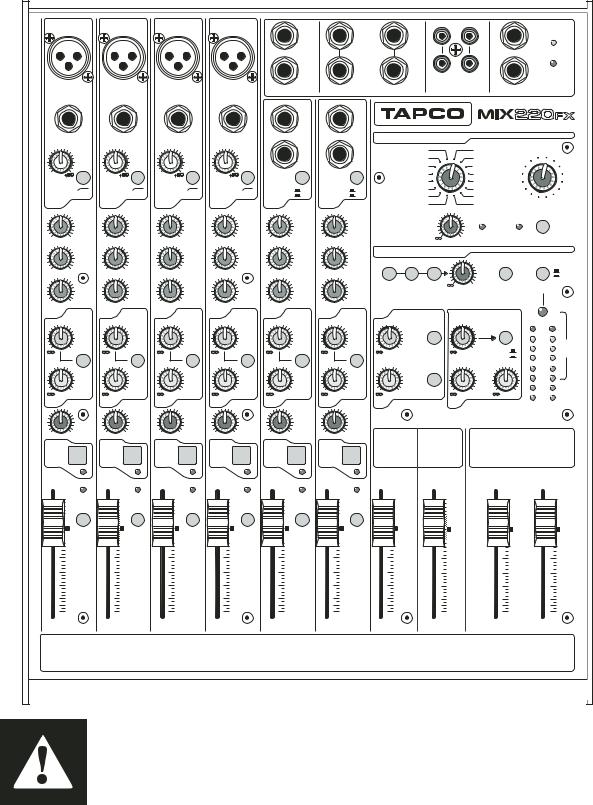
HERE’S A QUICK GLANCE AT ALL THE FEATURES PACKED INTO THESE MIXERS:
Mono mic/line channels:
•XLR microphone input jack
•1/4" TRS line-input jack
•Phantom power, globally switched
•Variable input trim (0 to +50 dB)
•Overload (OL) indicator LED
•Monitor Aux Send with Pre/Post switch
•Post-fader FX Aux Send
•3-band EQ
•75 Hz low-cut filter
•Pan control
•Mute switch (Mute/Alt 3-4 switch on 220FX)
•Solo switch
•Sub 1-2 and L-R assign switches (260 FX only)
•60 mm fader
Stereo line channels:
•Left and right 1/4" TRS line input jacks
•+4/–10 input level switch
•Monitor Aux Send with Pre/Post switch
•Post-fader FX Aux Send
•3-band EQ
•Balance control
•Mute switch (Mute/Alt 3-4 switch on 220FX)
•Solo switch
•Sub 1-2 and L-R assign switches (260 FX only)
•60 mm fader
Master section:
•60mm fader Main Mix controls
•60mm fader Alt 3-4 controls (220FX only)
•60mm fader Sub 1-2 controls (260FX only) with 6 Assign to Main Mix switches
•Balanced 1/4" TRS stereo main outputs
•12-segment stereo LED VU metering
•1/4" TRS Aux Sends with rotary level controls
•Stereo RCA tape out and tape in
•Stereo 1/4" Phones output
•Internal digital e ects section with e ects select control, variations control, input level control, FX overload LED, and FX bypass switch
•1/4" Footswitch jack to bypass the internal e ects, duplicates the FX bypass switch
•Source select switches for Control Room/Phones output
•Rotary Ctrl Room/Phones level control
•Tape to Main switch
•Solo mode switch (PFL/AFL)
•Aux Return 1 level control with Main/Sub 1-2 assign switch
•Aux Return 2 (FX) level control with Return to Aux 1 level control
•Inter-Planetary Space Drive control
•OK, we made that last one up, but we can pencil it in for next time
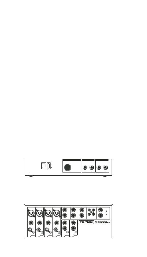
Rear panel:
•Main power switch
•Master +48V phantom power switch with LED indicator (except Mix.50)
•Left and Right XLR Main Outs
•Left and Right 1/4" Alt 3/4 Outs (220FX) or Sub 1-2 Outs (260FX)
•Left and Right 1/4" TRS Control Room outputs
•1/4" Insert jacks for channels 1-4 (260FX only)
HOOKUP DIAGRAMS
Active Speakers (Mackie SRM450s)
Small Club Gig
Stage Monitors
|
MAIN OUT |
ALT 3/4 OUTS |
CONTROL RM OUT |
|||
POWER |
PHANTOM |
|
|
|
|
|
ON |
ON |
LEFT |
|
BAL/UNBAL |
BAL/UNBAL |
|
|
RIGHT |
|
||||
|
|
|
4 |
3 |
RIGHT |
LEFT |
 100 - 120 VAC /
220 - 240 VAC 50 - 60 Hz 40W
TAPCO Juice |
Mono in/Stereo out Reverb |
Power Amplifier |
(optional) |
|
Headphones
Microphones |
|
|
|
|
|
|
|
|
|
|
|
|
|
|
|
1 and 2 |
|
|
|
|
|
|
|
|
|
|
|
|
|
|
|
|
1 |
|
1 |
|
1 |
|
1 |
|
1 |
|
|
|
|
L |
|
|
|
|
|
|
|
|
|
|
|
L |
L |
|
|
|
|
|
|
|
|
|
|
|
|
|
MON |
|
|
|
|
||
|
|
|
|
|
|
|
|
|
|
|
(MON0) |
|
|
|
POWER |
|
|
|
|
|
|
|
|
|
|
|
|
|
|
PHONES |
|
|
|
|
|
|
|
|
|
|
2 |
|
R |
R |
|
R |
PHANTOM |
|
|
|
|
|
|
|
|
|
FX |
|
|
|
IN |
OUT |
|
|
MIC |
|
MIC |
|
MIC |
|
MIC |
AUX SEND |
AUX RETURN |
FX RETURN |
CD/TAPE |
FOOTSW |
|||
|
INPUT |
|
INPUT |
|
INPUT |
|
INPUT |
INPUT/OUTPUT |
|
||||||
BAL/UNBAL |
BAL/UNBAL |
BAL/UNBAL |
BAL/UNBAL |
|
(MONO) |
|
(MONO) |
|
|
|
|
||||
|
|
|
|
|
|
|
|
|
L |
|
L |
|
|
|
|
|
|
|
|
|
|
|
|
|
BAL |
|
BAL |
|
|
|
|
|
LINE |
|
LINE |
|
LINE |
|
LINE |
|
OR |
|
OR |
|
|
|
|
|
|
|
|
|
UNBAL |
|
UNBAL |
|
|
|
|
||||
|
|
|
|
|
|
|
|
|
R |
|
R |
|
|
|
|
0 |
|
0 |
|
0 |
|
0 |
|
|
|
|
|
|
|
|
|
GAIN |
GAIN |
GAIN |
GAIN |
LINE |
+4 |
LINE |
+4 |
|
|
|
|
||||
1 |
75Hz |
1 |
75Hz |
1 |
75Hz |
1 |
75Hz |
5 |
-10 |
7 |
-10 |
|
|
|
|
EQ |
EQ |
EQ |
EQ |
6 |
EQ |
8 |
EQ |
|
|
|
|
||||
|
|
CD Player |
|
|
|
DAT Recorder |
|
Keyboard |
Drum Machine |
TAPCO S•5 or other |
|
Active Studio Monitors |
|||
|
|
Computer set-up
|
MAIN OUT |
ALT 3/4 OUTS |
CONTROL RM OUT |
|||
POWER |
PHANTOM |
|
|
|
|
|
ON |
ON |
LEFT |
|
BAL/UNBAL |
BAL/UNBAL |
|
|
RIGHT |
|
||||
|
|
|
4 |
3 |
RIGHT |
LEFT |
|
|
100 - 120 VAC / |
|
|
|
|
|
|
|
|
|
|
|
|
|
|
|
|
|
220 - 240 VAC |
|
|
|
|
|
|
|
|
|
|
|
|
|
|
|
|
|
50 - 60 Hz 40W |
|
|
|
|
|
|
|
|
|
|
|
|
|
|
|
|
|
|
|
|
|
|
|
|
Mono in/Stereo out Reverb |
|
|
|
|
||||
|
|
|
|
|
|
|
|
|
(optional) |
|
|
|
|
|
|
|
|
|
|
|
|
|
|
|
|
|
|
|
|
|
|
|
|
|
Headphones |
|
|
|
|
|
|
|
|
|
|
|
|
|
|
|
|
|
Note: Push down the CD/ |
Microphones |
|
|
|
|
|
|
|
|
|
|
|
|
|
|
|
|
TAPE [21] switch in the |
1 and 2 |
|
|
|
|
|
|
|
|
|
|
|
|
|
|
|
|
CONTROL ROOM section |
|
|
|
|
|
|
|
|
|
|
|
|
|
|
|
|
|
|
|
|
1 |
|
1 |
|
1 |
|
1 |
|
1 |
|
|
|
|
L |
|
to listen to the DAW |
|
|
|
|
|
|
|
|
|
|
|
L |
L |
|
|
|
output in the control room |
|
|
|
|
|
|
|
|
|
|
|
MON |
|
|
|
|
|||
|
|
|
|
|
|
|
|
|
|
|
|
(MON0) |
|
|
|
PHONES |
|
|
|
|
|
|
|
|
|
|
|
|
|
|
|
|
|
POWER |
|
|
|
|
|
|
|
|
|
|
|
2 |
|
R |
R |
|
R |
48V |
speakers and headphones. |
|
|
|
|
|
|
|
|
|
|
|
|
|
|
|
|
PHANTOM |
|
|
|
|
|
|
|
|
|
|
|
FX |
|
|
|
IN |
OUT |
|
Leave it up to listen to the |
|
|
MIC |
|
MIC |
|
MIC |
|
MIC |
AUX SEND |
AUX RETURN |
FX RETURN |
CD/TAPE |
FOOTSW |
||||
|
|
INPUT |
|
INPUT |
|
INPUT |
|
INPUT |
INPUT/OUTPUT |
|
|
||||||
|
BAL/UNBAL |
BAL/UNBAL |
BAL/UNBAL |
BAL/UNBAL |
|
(MONO) |
|
(MONO) |
|
|
|
|
main mix. Do not press |
||||
|
|
|
|
|
|
|
|
|
|
L |
|
L |
|
|
|
|
|
|
|
|
|
|
|
|
|
|
|
UNBAL |
|
UNBAL |
|
|
|
|
the TAPE TO MAIN [24] |
|
|
|
|
|
|
|
|
|
|
BAL |
|
BAL |
|
|
|
|
|
|
|
LINE |
|
LINE |
|
LINE |
|
LINE |
|
OR |
|
OR |
|
|
|
|
|
|
|
|
|
|
|
|
|
|
|
R |
|
R |
|
|
|
|
switch, or there will be |
TAPCO DB-1A |
0 |
|
0 |
|
0 |
|
0 |
|
|
|
|
|
|
|
|
|
feedback. |
|
75Hz |
|
75Hz |
|
75Hz |
|
75Hz |
|
-10 |
|
-10 |
|
|
|
|
|
|
|
GAIN |
GAIN |
GAIN |
GAIN |
LINE |
+4 |
LINE |
+4 |
|
|
|
|
|
||||
Direct Box |
1 |
|
1 |
|
1 |
|
1 |
|
5 |
|
7 |
|
|
|
|
|
|
EQ |
EQ |
EQ |
EQ |
6 |
EQ |
8 |
EQ |
|
|
|
|
Digital Audio Workstation |
|||||
|
|
|
|
|
|
|
|
|
|
|
|
|
|
|
|
|
|
Guitar |
|
TAPCO Link.USB or other |
|
Keyboard |
Drum Machine |
Digital Audio Interface |
|
7 |
|||
|
|
|
MIX FX SERIES FEATURES |
|
|
|
|
|
|
|
|
|
(MONO) |
|
|||||||||||
|
|
|
|
|
|
|
|
|
|
|
|
|
|
L |
|
||||||||
|
CHANNEL INPUTS |
|
|
|
|
|
|
|
|
|
|
|
|
|
|
|
|||||||
|
|
2 |
|
|
|
|
|
|
|
|
|
|
BAL |
|
|||||||||
|
|
|
|
|
|
|
|
|
|
|
|
|
|
|
|
|
|
|
OR |
|
|||
|
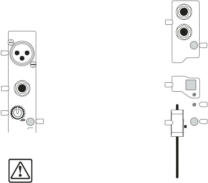
1. MIC (MICROPHONE) INPUTS |
3. GAIN CONTROL |
|
|
|
|
|
|
|
|
UNBAL |
|
|||||||||||
|
|
|
|
|
|
|
|
|
|
|
|
|
|
R |
|
||||||||
|
1 |
|
|
The MIX FX Series is |
(Mono Channels only) |
|
|
|
|
|
|
|
|
|
|
|
|
|
|
||||
|
|
|
|
|
|
|
|
|
|
|
|
||||||||||||
|
|
|
|
|
|
|
|
|
|
|
|
|
|
|
|
|
|
||||||
|
|
|
|
|
|
|
equipped with four rugged, |
If you haven’t already, please |
|
|
|
|
|
|
|
|
|
|
|
|
|
|
|
|
|
|
|
|
|
|
low-noise, phantom-powered |
read “SET THE LEVELS” on page 4. |
|
|
|
|
|
|
|
|
|
|
|
|
|
|
4 |
|
|
|
|
|
|
|
|
|
|
|
|
|
|
|
|
|
|
|
|
|
|||
|
|
|
|
|
|
|
|
|
|
|
|
|
|
|
|
||||||||
1 |
|
|
|
|
|
|
microphone preamplifiers, |
The GAIN control adjusts the |
|
|
LINE |
|
|
|
|
+4 |
|
||||||
|
|
|
|
|
|
providing up to 50 dB of crys- |
input sensitivity of the MIC and |
|
|
5 |
|
|
|
|
|
|
|
|
|
|
-10 |
|
|
|
|
|
|
|
|
|
|
|
|
|
|
|
|
|
|
|
|
|
|
||||
|
|
|
|
|
|
|
tal-clear amplification. Their |
LINE inputs. This allows signals |
|
|
6 |
|
|
|
|
|
|
|
EQ |
|
|||
|
|
|
|
|
|
|
balanced circuitry rejects all |
|
|
|
|
|
|
|
|
|
|
||||||
|
|
|
|
|
|
|
from the outside world to be |
|
|
|
|
|
|
|
|
|
|
|
|
|
|
|
|
|
|
|
|
|
|
|
Mix.220FX Stereo Channel |
||||||||||||||||
|
|
|
|
MIC |
|
|
manner of extraneous interfer- |
adjusted to optimal internal |
|||||||||||||||
|
|
|
|
|
|
|
|
|
|
|
|
|
|
|
|
|
|
|
|
|
|||
|
|
|
|
INPUT |
|
|
ence. Professional condenser, |
operating levels. |
|
|
|
|
|
|
|
|
|
|
|
|
|
|
|
|
|
|
|
|
|
|
|
|
MUTE |
|
|
|
|
|
|
||||||||
|
|
|
BAL/UNBAL |
|
|
dynamic, and ribbon mics all |
The GAIN control provides |
|
|
|
|
|
|
|
|
||||||||
|
|
|
|
|
|
|
15 |
|
5 |
|
|
|
|
|
|
|
|
|
|
|
|||
2 |
|
|
|
|
|
|
sound excellent through these |
50 dB of gain with the knob |
|
|
|
|
|
|
|
|
|
|
|
|
|||
|
|
|
|
|
|
XLR inputs. |
fully up. |
|
|
6 |
|
|
|
|
|
|
|
|
|
|
|
||
|
|
|
|
|
|
|
You can plug in almost any |
|
|
|
ALT |
|
|
|
|
|
|
||||||
|
|
|
|
LINE |
|
|
kind of balanced mic that has |
4. +4/–10 Switch |
|
|
3/4 |
|
|
|
|
|
|
|
|
|
|
|
|
|
|
|
|
|
|
|
|
|
|
|
|
|
|
|
|
|
|
|
|
5 |
|||
|
|
|
|
|
|
|
a standard XLR-type male mic |
(Stereo channels only) |
|
|
|
|
|
|
|
|
|
|
|
|
|
|
|
3 |
|
|
|
|
|
|
connector. See Appendix B |
Instead of a rotary gain |
|
|
|
|
|
|
|
10 |
|
|
OL |
|
|||
|
|
|
|
|
|
|
|
|
|
|
|
|
|||||||||||
|
|
|
|
|
|
for more information on XLR |
|
|
|
|
|
|
|
|
|
|
|
|
|
|
|
||
|
|
|
|
|
|
|
control, the stereo channels |
|
|
|
|
|
|
|
5 |
|
|
|
|
|
|
||
|
|
|
|
|
|
|
|
|
|
|
|
|
|
|
|
|
|
|
|
||||
|
|
|
|
|
|
|
|
|
|
|
|
|
|
|
|
|
|
|
|
||||
|
0 |
|
6 |
connectors. |
|
|
|
|
|
|
|
|
|
|
|
|
17 |
||||||
|
|
have a gain switch. This |
16 |
|
|
|
|
|
|
|
|
|
|
|
|
|
|||||||
|
|
|
|
|
|
|
|
|
|
|
|
|
|
|
|||||||||
|
|
|
|
|
|
|
|
|
|
|
|
|
|
|
|||||||||
|
|
|
|
|
|
The MIX FX Series provides |
|
|
|
|
|
|
|
|
|
|
|
|
|
||||
|
|
|
GAIN |
|
|
changes the input sensitivity |
|
|
|
|
|
|
|
|
U |
SOLO |
|
||||||
|
|
|
|
|
|
|
|
|
|
|
|
|
|
||||||||||
|
|
|
|
|
+48 VDC phantom powering |
|
|
|
|
|
|
|
|
|
|||||||||
|
|
|
|
|
|
|
|
|
|
|
|
|
|
||||||||||
|
|
|
|
75Hz |
|
|
of the channel to match either |
|
|
|
|
|
|
|
|
|
|
|
|
|
|
|
|
|
|
|
|
|
|
|
|
|
|
|
|
|
|
|
|
|
|
|
|
|
|||
|
|
|
|
|
|
|
|
|
|
|
|
|
|
|
|
|
|
|
|
|
|||
Mix.220FX Mono Channel |
on pins 2 and 3 of the mono |
|
|
|
|
|
|
|
5 |
|
|
|
|
|
|
||||||||
the –10 dBv consumer level or |
|
|
|
|
|
|
|
|
|
|
|
|
|
||||||||||
|
|
|
|
|
|
|
|
|
|
|
|
|
|
|
|||||||||
|
|
|
|
|
|
|
channels’ XLR MIC inputs. This |
|
|
|
|
|
|
|
|
|
|
|
|
|
|
|
|
|
|
|
|
|
|
|
the +4 dBu professional level. |
|
|
|
|
|
|
|
10 |
|
|
|
|
|
|
||
|
|
|
|
|
|
|
|
|
|
|
|
|
|
|
|
|
|
|
|
||||
|
|
|
|
|
|
|
can be turned on and o using |
|
|
|
|
|
|
|
|
|
|
|
|
|
|||
|
|
|
|
|
|
|
Most consumer equipment with |
|
|
|
|
|
|
|
|
|
|
|
|
|
|
|
|
|
|
|
|
|
|
|
the PHANTOM [58] switch. |
|
|
|
|
|
|
|
|
|
|
|
|
|
|
|
|
|
|
|
|
|
|
|
RCA connectors operate at |
|
|
|
|
|
|
20 |
|
|
|
|
|
|
|||
|
|
|
|
|
|
|
|
|
|
|
|
|
|
|
|
|
|
||||||
|
|
|
|
|
|
|
|
|
|
|
|
|
|
|
|
|
|
|
|
|
|
|
|
|
|
|
|
|
CAUTION: DO NOT connect a line- |
the –10 dBv level, while most |
|
|
|
|
|
|
|
30 |
|
|
|
|
|
|
|||
|
|
|
|
|
|
|
|
|
|
|
|
|
|
|
|
|
|
||||||
|
|
|
|
|
professional equipment with |
|
|
|
|
|
|
|
|
|
|
|
|
|
|
|
|||
|
|
|
|
|
|
|
|
|
|
|
|
|
|
|
|
|
|
|
|
||||
|
|
|
|
|
level device to a MIC input with the |
|
|
|
|
|
|
|
|
|
|
|
|
|
|
|
|||
|
|
|
|
|
1/4-inch phone jacks or XLR |
|
|
|
|
|
|
|
40 |
|
|
|
|
|
|
||||
|
|
|
|
|
|
|
|
|
|
|
|
|
|
|
|
|
|||||||
|
|
|
|
|
phantom power switched on. This |
|
|
|
|
|
|
|
50 |
|
|
|
|
|
|
||||
|
|
|
|
|
connectors operate at the +4 |
|
|
|
|
|
|
|
|
|
|
|
|
|
|||||
|
|
|
|
|
|
|
|
|
|
|
|
60 |
|
|
|
|
|
|
|||||
|
|
|
|
|
could damage the device. Use the |
|
|
|
|
|
|
|
|
|
|
|
|||||||
|
|
|
|
|
dBu level. |
|
|
|
OO |
|
|
|
|
|
|
||||||||
|
|
|
|
|
|
|
|
|
|
|
|
|
|
|
|
|
|
|
|
||||
|
|
|
|
|
LINE IN [2] jacks instead. |
|
|
|
|
|
|
|
|
|
|
|
|
|
|
|
|||
|
|
|
|
|
As you might expect, the |
|
|
|
|
|
|
|
|
|
|
|
|
|
|
|
|||
|
Do not use phantom power with tube or ribbon |
|
|
|
|
|
|
|
|
|
|
|
|
|
|
|
|||||||
|
+4 dBu level is higher (louder) |
Mix.220FX Stereo Channel |
|||||||||||||||||||||
|
microphones, as this may cause damage. |
||||||||||||||||||||||
|
than the –10 dBv level. If you |
||||||||||||||||||||||
|
|
|
|
|
|
|
|
|
|
|
|
|
|
|
|
|
|
|
|
|
|
|
|
|
2. LINE INPUTS |
|
have trouble getting enough volume from a signal |
||||||||||||||||||||
|
|
connected to one of these stereo channels, push in |
|||||||||||||||||||||
|
|
|
These inputs can accept 1/4" TRS balanced and TS |
||||||||||||||||||||
|
|
|
the +4/–10 switch to get more volume. |
|
|
|
|
|
|
||||||||||||||
|
unbalanced plugs from any line-level instrument, e ects |
|
|
|
|
|
|
||||||||||||||||
|
|
|
|
|
|
|
|
|
|
|
|
|
|
|
|
|
|||||||
|
device, or tape player. They can be driven by virtually |
5. OL LED |
|
|
|
|
|
|
|
|
|
|
|
|
|
|
|
||||||
|
any line-level signal, from –45 dBu up to +18 dBu. |
This handy LED (Light Emitting Diode) lets you |
|||||||||||||||||||||
There are two line-inputs for each stereo channel, |
know that the signals going into the mixer are |
|
a left and a right. When connecting a stereo device |
||
adjusted to the correct level, not too strong to cause |
||
(two cords), use both the left (mono) input and the |
||
distortion and not too weak to be lost in noise. |
||
right input. |
||
After you connect a microphone or line-level |
||
When connecting a mono device (just one cord), |
||
component to the mixer, do a sound test and adjust |
||
always use the left (mono) input and plug nothing |
||
the GAIN control until this handy LED flickers just |
||
into the right input. A trick called “jack normalling” |
||
occasionally. If it is glowing constantly, turn the GAIN |
||
causes the signal to appear on both sides. |
||
down. If the LED is doing almost nothing, turn it up. |
||
|
8
CHANNEL CONTROLS
The channel strips have various controls, depending on the model and whether it is a mic/line (mono) channel or a stereo channel.
The output from each channel strip passes on to the left and right main mix. Two auxiliary signals can be tapped o and sent to monitors or e ects processors. The block diagrams on pages 23-24 show how the signal flows through each mixer.
LOOK |
UNITY GAIN |
|
The U symbol on most of the |
||
|
||
|
controls, stands for “unity gain,” |
|
|
meaning there is no change |
|
CLOSER in signal level. Once you have |
||
|
adjusted the input signal to line- |
|
level, you can set every control at U, and your signals will travel through the mixer at optimal levels.
EQUALIZATION
Each EQ control provides up to 15 dB of boost and cut, with no change to the signal (0 dB) in the center position. The Mix.220FX has three-band EQ on all the channels, while the Mix.260FX has threeband EQ with variable mid on the mono channels, and four-band EQ on the stereo channels.
Although you can bring a sound to life with proper EQ, you can also mess things up. If you max the EQs on every channel, you’ll get mix mush, not to mention driving your mix levels near or beyond clipping. So equalize subtly; use cut as well as boost.
6. 75Hz Low-Cut Switch (Mono Channels only)
This switch cuts the bass frequencies below 75 Hz. We recommend that you use the Low-Cut switch on every microphone application except kick drum, bass guitar, bassy synth patches, or recordings of earthquakes. These aside, there isn’t much down
there that you want to hear, and filtering it out makes the low stu you do want much more crisp and tasty.
7. HI EQ
Turning this clockwise boosts the level of all frequencies above 12 kHz. Turning it counterclockwise cuts the levels.
Use this wisely to add sizzle to cymbals or an overall sense of transparency or edge to keyboards, vocals, guitar, and bacon frying. Turn it down a little to reduce sibilance or hide tape hiss.
8. MID EQ
Turning this clockwise boosts the level of frequencies at and around 2.5 kHz on the 220FX. Turning it counter-clockwise cuts the levels.
The 260FX has a sweepable MID EQ on the mono channels (see 9 next), and two discrete MID EQ controls on the stereo channels, with center frequencies at 3 kHz and 500 Hz [8a].
The midrange frequencies include the upper male and lower female vocal ranges, and the fundamentals
and harmonics for many instruments.
9. MID FREQ
(Mix.260FX Mono Channels only)
This allows you to change the center frequency for the MID EQ filter so you can zero in more accurately on the precise narrow band of frequencies you want to boost or cut. It ranges from 100 Hz to 8 kHz.
10. LOW EQ
Turning this clockwise boosts the level of all frequencies below 80 Hz. Turning it counterclockwise cuts the levels.
Frequencies of 80 Hz and below represent the punch in bass drums, bass guitar, fat synth patches, and hightestosterone male singers.
AUXILIARY
In addition to the main mix output, the mixer provides two auxiliary mixes, which you can send to parallel e ects
processors and stage monitors. The AUX SEND knobs adjust
how much of each channel is tapped o , added to the aux mix, and sent out via the AUX SEND [45] jacks.
On the stereo channels, the AUX knob controls a mono sum of the channel’s stereo signals. For instance, channel 5 (L) and 6 (R) mix together to feed that channel’s AUX send knobs.
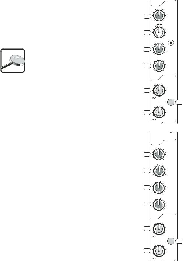
1 EQ
U
7 
 HIGH
HIGH
12kHz
-15 +15
MID 9 
 FREQ
FREQ
100 8k
U
8
 MID
MID
-15 +15
U
10 
 LOW
LOW
80Hz
-15 +15
AUX
U SEND
11 
 1
1
MON
+15
12
U
PRE
13 
 2
2
FX
+15
Mix.260FX Mono Channel
LINE
 +4
+4
5 -10
-10
6EQ
|
U |
7 |
HIGH |
|
12kHz |
-15 |
+15 |
|
U |
8 |
MID |
3kHz |
-15 +15
U
8a 
 MID
MID
500Hz
-15 +15
U
10 
 LOW
LOW
80Hz
-15 +15
AUX
U SEND
11 
 1
1
MON
+15
12
U
PRE
13 
 2
2
FX
+15
Mix.260FX Stereo Channel
9
Loading...