

Tanita PH-740 Owner's Manual
Eng
Please keep this manual in a safe place, and make
sure it is readily available whenever necessary.
Please use this product only after carefully reading
this manual and fully understanding its contents.
HANDRAIL SCALE
PH-740
INSTRUCTION MANUAL

WARNING
• Inserting and Removing the AC adapter to reduce the risk of electric shock or product damage, never insert or remove the AC adapter with wet hands.
• Do not under any circumstances dismantle or alter the device, as this could result in electric shock or injury as well as adversely affecting the precision
of measurement.
• To prevent fire hazard use only a correctly wired (120V AC) outlet, and do not use a multiple outlet extension cable.
CAUTION
• Please make sure you place the scale on a level and stable surface. If the equipment is used when the scale is unstable, because not all feet are on the
surface, there may be a risk of injury or inaccurate measurement. Measurement may be inaccurate when the scale is placed on a thick-pile rug or carpet.
• Never jump on the scale, there may be a risk of injury and malfunction of the equipment.
• Do not hang on the handrail.
• The equipment must be used with the included AC adapter only.
• Do not insert or remove the AC plug by the cable.
• Do not place a finger into any gap or any hole of the equipment. You may be injured.
• Please use caution when adjusting the height rod to prevent injury.
• Please return the height rod to the storage position after completion of measurement.
• Please do not touch or lean on the height rod or the display during weighing as this will reduce accuracy.
Maintenance
This is a precision manufactured and accurately calibrated product. Please observe the following instructions.
• If the equipment is moved to a place with a temperature difference of 18˚F/10˚C or more, leave if for at least two (2) hours before use.
• Avoid subjecting the equipment to excessive shocks or vibrations.
• Never disassemble or adjust the equipment, as this may cause malfunctions.
• When not in use for an extended time, unplug the AC adapter from the outlet.
• Do not wipe the equipment with corrosive chemicals (benzene, acetone, etc.). Please use a neutral detergent to clean the equipment.
• Do not use cellular phones or microwave therapy equipment near this equipment.
It may not measure correctly due to equipment malfunction.
• When disposing of this equipment, please do so in accordance with the prevailing regulations in your country, state and city.
• If an unauthorized person attempts to disassemble or repair any part of the equipment, the warranty will become invalid. When the unit malfunctions,
please consult your nearest Tanita sales office or agent.
Caution Symbols
For optimum performance and safety, please familiarize yourself with the Caution Symbols below. These symbols are designed to alert the user to
potential hazards when using this equipment. Ignoring these Caution Symbols may result in serious injury, or damage to the product. Please be sure to
review before proceeding with the INSTRUCTION MANUAL.
WARNING
This symbol indicates the possibility of serious injury if the product is mishandled or instructions are ignored.
CAUTION
This symbol indicates the possibility of physical injury or equipment damage if instructions are ignored.
This symbol indicates general precautions that should be taken when using this product.
2. Safety Notes
1. Table of Contents
Eng
Eng
2 3
2. Safety Notes
••••••••••••••••••••••••••••••••••••••••••••••••••••••••••••••••••••••••••••••••••••••••••••••
2
3. Based on NIH / WHO BMI Guidelines
•••••••••••••••••••••••••••••••••••••••••
3
4. Part Names & Accessories
•••••••••••••••••••••••••••••••••••••••••••••••••••••••••••••••••••
3
5. Assembly Instructions
•••••••••••••••••••••••••••••••••••••••••••••••••••••••••••••••••••••••••••
4
6. Operation by AC adapter
•••••••••••••••••••••••••••••••••••••••••••••••••••••••••••••••••••••
7
7. Operation by batteries
•••••••••••••••••••••••••••••••••••••••••••••••••••••••••••••••••••••••••••
7
8. Operation
••••••••••••••••••••••••••••••••••••••••••••••••••••••••••••••••••••••••••••••••••••••••••••••••••••
8
9. Measuring height procedure
••••••••••••••••••••••••••••••••••••••••••••••••••••••••••••
10
10.Output data format
••••••••••••••••••••••••••••••••••••••••••••••••••••••••••••••••••••••••••••••
11
11.Specifications
••••••••••••••••••••••••••••••••••••••••••••••••••••••••••••••••••••••••••••••••••••••••••
13
12.Troubleshooting
••••••••••••••••••••••••••••••••••••••••••••••••••••••••••••••••••••••••••••••••••••
13
3. Based on NIH/WHO BMI Guidelines
Under Weight
Normal Range
Pre obese
Obese
Obese
Obese
CLASS l
CLASS ll
CLASS lll
BMI
18.5
18.5
BMI 25
25
BMI 30
30
BMI 35
35
BMI 40
BMI
40
/
Adjust height for BMI
ON/ZERO
Turns the power on and
sets zero
BMI
Select BMI mode
kg/lb
Select “kg” or “lb” for unit
measurement
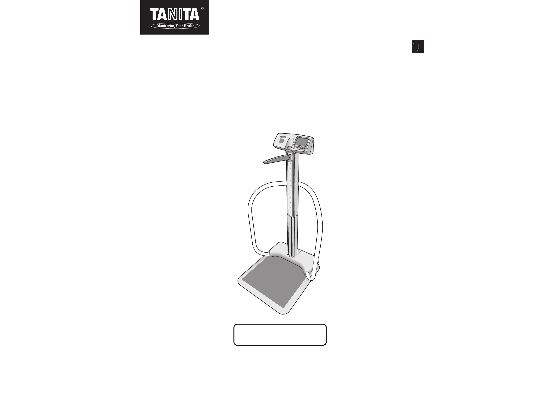
4. Part Names & Accessories
Battery Case
Platform
Height Rod Arm
Adjustable Feet
Wheel
AC Adapter
Instruction Manual
Clip x 3
•The clips are for holding
the AC adapter cable and
USB cable. Attach the clips
to the rear of the pillar as
illustrated.
Screw x 8
Accessories
Display Box
Handrail
Eng
5
Eng
4
1. List of Components
Base (fully assembled and pre-wired to display assembly)
Cable (Base side)
Lower Pillar Assembly
Screw
Cable (Top Head Display Assembly Side)
Top Head Display Assembly (fully assembled and pre-wired to base)
Back Cover
Front Cover
Top Height Rod Assembly (fully assembled with pivoting height measuring lever)
Height Rod Arm
Lower Height Rod Assembly
Handrail
Brace
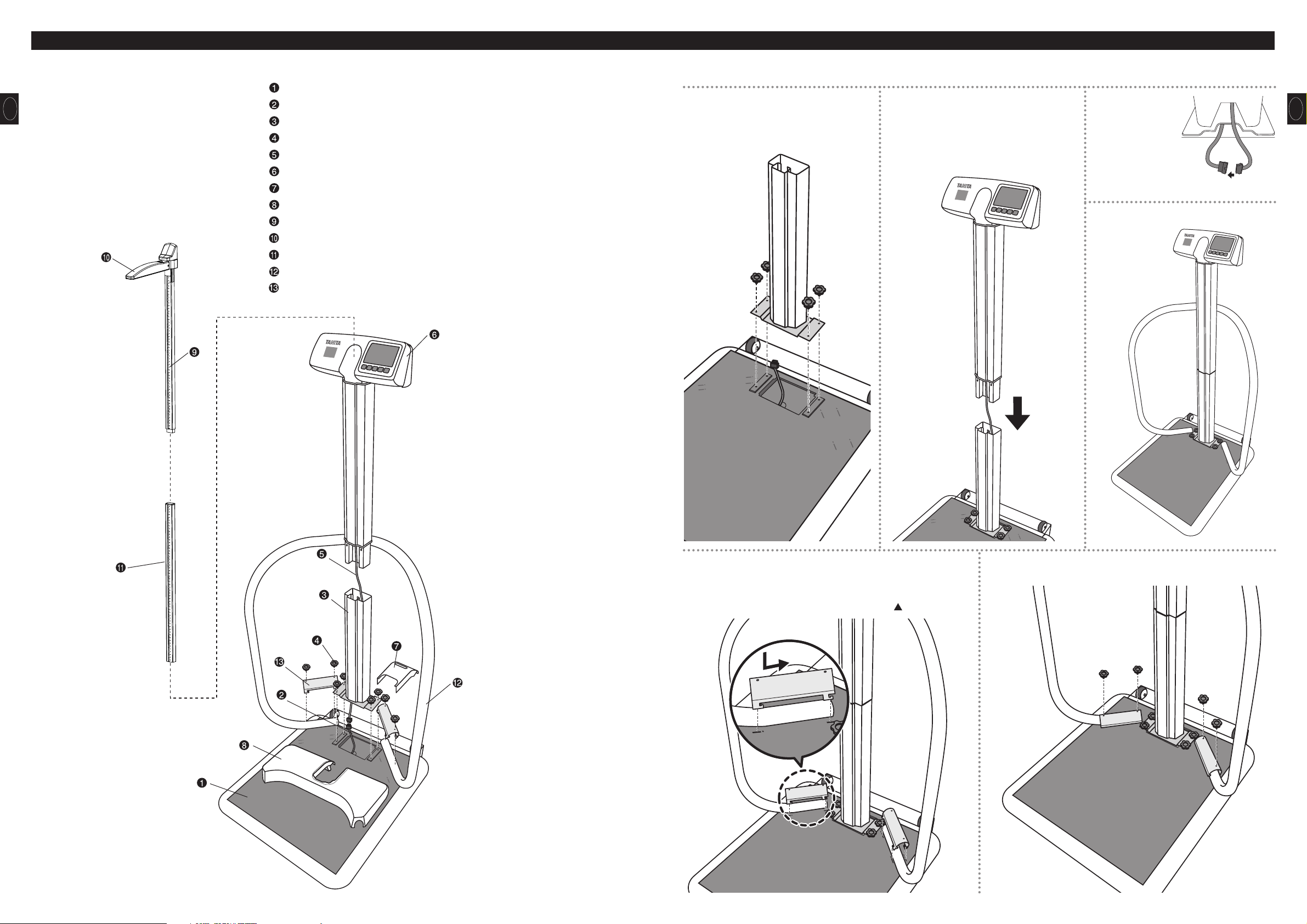
5. Assembly Instructions
2. Assembly
2) Assemble the Top Head Display into the
Lower Pillar assembly while carefully
inserting the cable into Lower Pillar
assembly and extending it the full length
of the Lower Pillar.
3) Connect the
Cable from the
bottom of the
lower pillar
assembly to
the cable on
the base.
4) Place the Handrail on the Base.
5) Insert the tabs of the brace into the slot. Putting your weight on
the handrail to adjust its position will facilitate insertion of the
brace into the slot.
Slide the brace completely to the end (Position mark).
6) Clamp the handrail to the brace using the four screws.
*Tighten the screws completely.
1) Install the Lower Pillar Assembly into
the Base using the four (4) Screws while
carefully avoiding pinching the cable.
*Tighten the screws completely.
 Loading...