

Page 1
Z
E
R
O
P
O
U
N
D
S
K
I
L
O
S
O
N
O
F
F
P
o
u
n
d
s
K
i
l
o
s
www.tanita.com
P
u
s
h
“
O
N
”
b
u
t
t
o
n
a
n
d
w
a
i
t
u
n
t
i
l
z
e
r
o
a
p
p
e
a
r
s
b
e
f
o
r
e
s
t
e
p
p
i
n
g
o
n
s
c
a
l
e
W
E
I
G
H
T
Model 3500
Stand-on Scale
Cautions and Warnings ......................................................1
Assembly Instructions ........................................................2
Before Assembly
Assembling the Scale
Attach Control Panel Box
Leveling Platform
Battery Charging ..................................................................3
Charging the Battery
Product Description ............................................................3
Control Panel Box
Special Features
Specifications
Operating Instructions ........................................................4
Using the Zero Function
Taking a Weight Measurement
Care and Maintenance ........................................................5
Cleaning
Calibration
Troubleshooting Guide ........................................................5
Parts Lists ............................................................................6
Warranty................................................................................7
OPERATOR’S MANUAL
Page 2

T
anita Corporation’s line of electronic scales uses the most
sophisticated microprocessor technology available. Each precision
instrument is designed to provide accurate, reliable and repeatable weight
measurements, as well as many other features that make the weighing
process simple, fast and convenient.
This operation manual contains instructions for use. In order to achieve
satisfactory results, the operator must read this manual thoroughly before
using this scale. If questions arise regarding this scale or its use, please
contact Tanita Corporation of America, Inc.
CAUTIONS AND WARNINGS
Cautions
• To ensure proper operation of the 3500 Stand-on Scale, this operator’s manual should
be read carefully before operation. Keep this manual available for future reference, and
also for use in the orientation of new personnel.
• Use only the appropriate connecting cable designed specifically for use with this
monitor. If the cabling provided with this unit becomes cracked or damaged, it should
be repaired or replaced immediately.
• If the scale becomes damaged, it should not be operated until properly serviced. All
repairs should only be performed by authorized Tanita Corporation service personnel.
• Scales are designed for static weighing of patients only. No scale should be used for
patient transfer. Tanita Corporation assumes no responsibility for patient injury
or scale damage should this caution be ignored.
• Do not leave patients unattended on the scale.
Warnings
Failure to comply with the following will void scale warranty:
• Do not gas sterilize or autoclave the scale.
• Do not place liquids on top of the scale read-out console.
• Do not exceed recommended weight limit of 500 lb./225 kg. for this scale.
• Scales contain delicate sensors. Do not bang into doors, elevators, etc., as damage
may result.
1
Page 3
ASSEMBLY INSTRUCTIONS
Before Assembly
NOTE: Carefully inspect the carton for shipping damage
before unpacking. If damage is found, contact your
shipper or Tanita Corporation immediately. Claims must
be filed with the shipper as soon as possible after receipt
of the damaged package.
One carton containing: Handlebar with control panel
box, scale platform with wheels, battery transformer and
mounting bracket, C-clamp, and eight (8) locknuts, four
(4) 1/4 x 20 allen head screws, washers, clips, and an
allen wrench.
IMPORTANT: After assembly of the scale, charge the
battery in the control box using the procedure under
“Charging the Battery” on page 3. This will restore any
power lost during storage and shipment.
Tools Needed: Adjustable wrench or 5/8" socket or
open-end wrench.
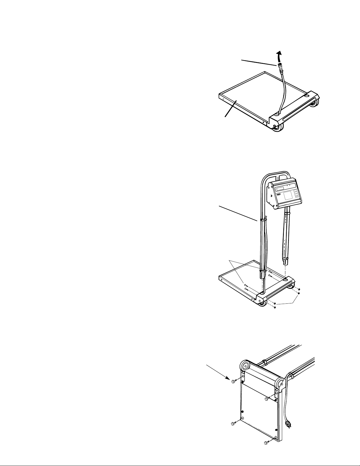
Assembling the Stand-on Scale
1. Place the platform on the floor.
2. Turn the platform up on its front edge.
3. Thread the control cable with connector through the
right handlebar mounting hole in the wheel cover.
Insert the cable into the keyway in the mounting hole.
(Fig. 1)
4. Lay the platform down. Insert the handlebar into the
(2) two mounting holes in the wheel cover. Make sure
the control cable is seated in the mounting hole
keyway. (Fig. 2)
5. Line up the holes in the handlebar with the holes
in the wheel cover. Secure the handlebar to the base
using 1/4 x 20 allen head screws, washers, and
locknuts. Tighten with the allen wrench supplied.
6. Tilt the scale on its front edge and rest the handlebar
on the floor. Screw a leveling foot into each corner of
the platform bottom. Leave about 1/4" of thread
showing. (Fig. 3) Spacers are located over each foot
stud to prevent turning the foot in too far. DO NOT
REMOVE THE SPACERS.
Z
E
R
O
P
O
U
N
D
S
K
I
L
O
S
O
N
O
F
F
P
o
u
n
d
s
K
i
lo
s
ww
w.tanita.com
P
u
s
h
“
O
N
”
b
u
t
t
o
n
a
n
d
w
a
i
t
u
n
t
i
l
z
e
r
o
a
p
p
e
a
r
s
b
e
f
o
r
e
s
t
e
p
p
i
n
g
o
n
s
c
a
l
e
W
E
I
G
H
T
2
Fig. 1
Fig. 2
Fig. 3
Rubber Mat
63957
Control
Cable with
Connector
63826
Handlebar
63948
Leveling Feet
63879
Allen Head Screw
Lock Nuts
Page 4

Attach Control Box Assembly to Scale
1. Find the control panel box, transformer bracket,
C-clamp and 4 locknuts.
2. Attach the control panel box to the center handlebar
rail using the C-clamp. Also mount the transformer
bracket on two of the studs extending through the
C-clamp. Secure the control panel box with the
(4) locknuts.
3. Attach the cable lead to the 5-prong jack (63932)
on the side of the control panel box. Secure by turning
the knurled ring. Clip cable to the left handlebar with
clips supplied.
Leveling the Platform
To level or adjust the height of the scale platform,
carefully tilt the scale back on the handlebar and turn the
leveling feet either into or out of the platform underside.
NOTE: Adjust platform height so that bottom edge of
platform or wheels do not touch floor or carpet. An
incorrect reading will result if the platform touches the
floor or carpet.
BATTERY CHARGING
The rechargeable battery in this scale is similar to the
no-maintenance lead-acid batteries used in automobiles.
Since the battery is sealed, no checking of water level
or adding of water to the battery is necessary. However,
recharging at proper intervals and proper storage
procedures are necessary, similar to an automobile
battery. A fully charged battery will provide approximately
250 normal weighings before requiring recharging.
When the display flashes “Lo-b,” the battery needs to
be recharged.
Charging the Battery
A. Plug the battery charger power cord into the 3-prong
jack on control panel box. Secure by turning the
knurled ring.
B. Plug the battery charger into a 120 VAC outlet.
C. The battery will fully charge in 8 hours. THE SCALE
MAY BE USED WHILE THE BATTERY IS CHARGING.
NOTE: The specially designed charger built into this scale
prevents the battery from being overcharged. Use of a
charger or adapter other than the one designed for this
scale can result in SERIOUS DAMAGE TO THE SCALE
OR BATTERY.
Optimum battery life will be obtained if the scale is
operated and stored connected to 120 VAC. Always check
the plug to see if the scale is charging before moving.
STORAGE: When storing the scale for an extended
period of time (and the unit is not connected to a 120
VAC), the battery should be fully charged. The battery
should then be charged every three months. A
discharged battery should be recharged as soon as
possible to prevent its useful life from decreasing
significantly. A discharged battery left in the scale can
leak and cause permanent damage to the battery and
scale. Store the unit in a cool, dry place.
PRODUCT DESCRIPTION
Control Panel Box
The scale control panel keypad has four membrane
switches. The POUNDS, KILOS, and ZERO switches
have both primary and secondary functions listed below.
Only the primary functions are listed on the switch.
3
Keypad
63911
Control Box
Clamp 63935
AC Adapter
Bracker 63925
ZERO
POUNDS
KILOS
ON
OFF
Pounds
Kilos
www.tanita.com
Push “ON” button
and wait until zero
appears before
stepping on scale
WEIGHT
Page 5

Special Features
Tanita Corporation’s electronic scales come standard with
these special features:
1. Autozero: The scale will automatically display “0” when
turned on. If a foreign object is placed on the platform
before turning the scale on, it will automatically zero
out that object’s weight.
2. English-Metric Readout: You may switch between
metric (kilos) and English (pounds) readouts before or
after a reading, and the scale will convert one reading
to the other.
3. Recalculate Weight: If the first reading of a patient’s
weight is suspect, a second reading can be taken
without removing the patient from the scale. To reweigh
the patient, simply depress the Zero switch.
4. Average Weight: In most cases, the 3500 Scale
displays an actual weight based on a series of
consistent stable measurements. However, if the
wheelchair/patient keeps moving, the scale may not
get the readings required to give a “stable weight.” In
these instances an average weight can be determined
by activating the Average Locking feature. Depress
the Pounds (or Kilos) switch (dependent upon
measurement mode). The indicator light should start
flashing. A weight should appear in place of the moving
dashes. Depress the Pounds or Kilos switch again to
deactivate the feature.
5. Zero Ability: The operator can “zero out” the weight of
a blanket, etc., upon which a patient is to be weighed.
Specifications
Dimensions
Height ......................................................................42"
Width ........................................................................19"
Length ......................................................................23"
Weight (no package included) ..............................62 lb.
Power Requirements
Input Power ..........................................120 VAC/60 Hz
Rechargeable Battery ..........................................8 Volt
Minimum Charge Life ..............................250 Readings
Recharge Time ................................................8 Hours
Operating Conditions
Temperature/Humidity ............................Normal Room
Temperature and Humidity
Scale Description
Type ..........................................................Strain Gauge
Maximum Capacity ................................500 lb./227 kg.
Resolution ................................................0.1 lb./0.1 kg.
Accuracy............................................± 0.1 lb./± 0.1 kg.
Maximum Zero Weight ..........................12.5 lb./5.6 kg.
OPERATING INSTRUCTIONS
Using the Zero Function
When using the Stand-on Scale, the weight of any object
accompanying the patient (blanket, etc.) must be taken
into account during a weighing. Weigh the object(s) by
themselves to determine their weight and subtract this
weight from the combined weight of patient and object(s).
METHOD 1
1. Scale is off.
2. Place the object (blanket, etc.) on the scale platform.
3. Turn the scale on. The scale will now zero out
the weight of the chair leaving a “0” reading
on the display.
METHOD 2 – Use for objects under 12.5 lbs.
1. Turn the scale on. Wait for display to read “0.”
2. Place the object (blanket, etc.) on the scale platform.
The display will read the object’s weight.
3. Depress the Zero button to zero out the weight of the
object. The display should read “0.”
Note: The Zero button has a dual function. If the weight
of the object is greater than 12.5 lbs., the scale will
reweigh the object instead of zeroing it out when the
button is depressed. IN THIS CASE, YOU MUST USE
METHOD 1 TO ZERO OUT THE WEIGHT OF THE
OBJECT.
Switch
On/Off
Kilos
Pounds
Zero
Primary Function
Depress to turn scale
on or off.
Depress to display
weight in kilograms
(light over switch will
illuminate to indicate
kilogram mode).
Depress to display
weight in pounds
(light over switch will
illuminate to indicate
pounds mode).
Zeros out the weight
of a foreign object
(e.g. blanket placed
on platform).
Secondary Function
While in Kilos mode, depress for average
reading when excessive movement
prevents stationary measurement.
Depress after any reading to “lock”
reading. Reading remains displayed for
approximately 1 minute after patient is
removed from scale, or until switch is
depressed again. Kilos light will flash to
indicate average or locked reading.
Depress while in Pounds mode to
average reading.
Depress after any reading in pounds
mode to “lock” in reading. Light will flash
to indicate average or locked reading.
Depress after initial weight is taken to
reweigh individual.
4
Page 6

Calibration
Note: Your scale has been accurately calibrated at the
factory; however, there is always a possibility that
calibration has changed due to jarring in shipping. The
following procedure should be followed to check and/or
correct any error in calibration.
1. Depress On/Off switch on scale and wait for display
to show “0.”
2. Place an accurately known weight on the platform.
3. If display is other than know weight, then scale is out
of calibration.
4. Remove the 4 screws nearest the face switch panel (2
on each side – near the aluminum trim). Slightly loosen
the remaining 4 screws (2 on each side), but do not
remove.Lift off the top portion of the head. Be careful,
since it is attached to the bottom portion with a
ribbon cable. Looking at the bottom from of the head
(underneath), you will see 2 small adjustment screws.
The left metal screw (VR2) is for coarse adjustments; it
adjusts for large errors. The right plastic screw (VR1) is
for fine adjustments; it adjusts small errors.
5. Turn the left metal coarse calibration screw (VR2) in
small increments, CLOCKWISE to increase weight or
COUNTERCLOCKWISE to decrease weight. In most
cases, this is the only adjustment needed.
6. If necessary, make adjustments with the right screw
(fine adjustment). CLOCKWISE to decrease weight;
COUNTERCLOCKWISE to increase weight.
7. Remove weight and depress the Zero switch. Wait for a
display reading of zero. Again add known weight to
platform. If reading is correct, no further adjustments
are necessary. If reading is incorrect, repeat steps 5
and 6 until correct reading is obtained.
TROUBLESHOOTING
The following guide will help you solve common problems:
Taking a Weight Measurement
1. Once an object’s (blanket, etc.) weight has been
zeroed out and the display is reading “0,”
have the patient stand on the scale platform.
2. The moving dashes will lock in and display the
patient’s actual weight.
3. Weight measurement should automatically be
displayed on the control panel box.
• Measurement automatically defaults to pounds. If
kilograms are required, depress the Kilos switch.
• If a reweigh is required, depress the Zero switch.
4. Excessive movement may prevent a repeatable
reading. In this case, a series of moving dashes
continues to appear on the console, rather than a
weight reading. If moving dashes persist, activate the
“Average Lock” by depressing the appropriate Pounds
or Kilos switch to obtain an average reading of the
patient’s weight.
Note: This reading is now an instantaneous average
of weights that the computer calculates.
5. After weight is obtained and recorded, have the patient
step off the scale.
6. Depress On/Off switch to turn scale off.
IMPORTANT: Make certain the platform height is
adjusted so the wheels and platform bottom edge do
not touch the floor or carpet. An incorrect patient weight
reading will result if bottom of the platform touches. (See
“Leveling the Platform” on page 3.)
CARE AND MAINTENANCE
Proper care and cleaning of all Tanita Corporation scales
and accessories is essential to ensure a long life of
accurate and effective operation. In addition to routine
cleaning, include a regular check of all structural
apparatus to ensure stability.
Cleaning
Disconnect battery charger from scale before cleaning.
1. All external surfaces can be wiped clean with a damp
cloth or tissue. Mild soap and water solution may be
used. Wipe unit dry with a clean, soft cloth.
2. DO NOT immerse control panel box into cleaning or
other liquid solution.
3. DO NOT use isopropyl alcohol or other solutions to
clean surface of control panel box.
4. Check for overall appearance of the whole scale for
any obvious damage, wear and tear. Inspect the AC
charger for cord cracking or fraying or for broken or
bent prongs.
5
PROBLEM
Scale won’t turn on
Incorrect patient weight
readings
Display flashes “Lo-b”
Patient weight readings
consistently too high or
too low
SOLUTION
A. Make sure plug in firmly plugged into wall power
source.
B. Check fuses or circuit breaker to ensure voltage
is present in wall power source.
A. Platform too low and hitting platform feet or
carpet. Increase platform height. See “Leveling
the Platform” on page 3.
B. Person, other than person being weighed,
touching or leaning on scale handlebar.
C. Weight of wheelchair or chair not taken into
account. See “Operating Instructions” on page 4.
D. Platform not level. See “Leveling the Platform” on
page 3.
Recharge battery. See “Charging the Battery”
on page 3.
Check scale calibration and calibrate if necessary.
See “Calibration” on page 5.
Page 7

Qty Part Description Location
1 RES. MOX .47 1W 5% R4
1 RES. CF 2.7 1/4W 5% R2
1 RES. CF 10 1/4W 5% R12
1 RES. CF 22 1/4W 5% R7
1 RES. CF 150 1/4W 5% R29
1 RES. CF 120 1/4W 5% R6
2 RES. CF 560 1/4W 5% R13
R14
4 RES. CF 1K 1/4W 5% R3
R5
R15
R50
1 RES. MF 2.00K 1/4W 1% R48
2 RES. CF 2.2K 1/4W 5% R18
R37
4 RES. CF 3.9K 1/4W 5% R1
R16
R22
R32
2 RES. MF 4.02K 1/4W 1% R44
R45
1 RES. CF 4.7K 1/4W 5% R21
1 RES. MF 9.31K 1/4W 1% R49
2 RES. CF 10K 1/4W 5% R38
R40
2 RES. CF 15K 1/4W 5% R27
R47
7 RES. CF 27K 1/4W 5% R8
R9
R10
R11
R17
R43
R46
6 RES. CF 33K 1/4W 5% R19
R24
R25
R28
R30
R31
2 RES. CF 150K 1/4W 5% R26
R23
1 RES. MF 301K 1/4W 1% R34
4 RES. MF 402K 1/4W 1% R35
R36
R41
R42
1 RES. CF 470K 1/4W 5% R20
1 RES. CF 3.3M 1/4W 5% R39
1 RES. CF 1/4W 5% R33
1 RES. NETWORK 220 RN1
1POT 1K 1 TURN VR1
1POT 25K 20 TURN VR2
1 CAP CER NPO 22PF 50V C4
1 CAP CER 100PF 50V C5
1 CAP CER .001UF 50V C18
1 CAP MY .001UF 100V C9
1 CAP PS AX .0047UF 50V C17
1 CAP TANT 4.7UF 25V C15
3 CAP MONO CER .1UF 50V C19
C20
C8
1 CAP PC AX .1UF 100V C21
1 CAP MONO CER .22UF 50V C13
Qty Part Description Location
1 CAP MONO CER .47UF 50V C22
3 CAP TANT 1UF 35V C3
C14
C16
1 CAP ELE 4.7UF 50V C2
2 CAP ELE 47UF 25V C6
C10
1 CAP ELE 100UF 25V C11
3 CAP ELE 470UF 25V C1
C7
C12
1 CERAMIC RES. 4.00MHz X1
4 TRANS. PNP PWR 2N6728 Q1
Q2
Q3
Q4
2 TRANS. PNP PWR TIP32 Q5
Q7
1 TRANS. PNP GEN MPS3702 Q8
13 TRANS. NPNGEN MPS3704 Q6
Q9
Q10
Q11
Q12
Q13
Q14
Q15
Q16
Q17
Q18
Q19
Q2
4 DIODE SIGNAL 1N4148 CR1
CR7
CR14
CR15
1 DIODE ZENER 9.1V 1N4739A CR2
10 DIODE REC 600V 1N4005 CR3
CR4
CR5
CR6
CR8
CR9
CR10
CR11
CR12
CR13
2 IC REG 5V 7805 U1
U2
1 IC MICROPROCESSOR U3
2 IC DUAL OP-AMP LM358N U4
U7
1 IC HEX INV BF CD4049UBE U5
1 IC QUAD B SW CD4016BE U6
1 IC OP-AMP ICL7652CPD U8
1 IC DUAL COMP LM393N U9
2 HEADER 2PIN .156C J2
J3
1 HEADER 5PIN .156C J5
1 IC SOCKET 16PIN J1
1 IC SOCKET 28PIN U3
1HEATSINK TO-220 Q7
4 SCREW, 4-40 X 3/8
4 NUT, 4-40 KEPS
PARTS LIST
CIRCUIT BOARD
Description Part No.
Keypad 63911
Battery Transformer 63812
Rechargeable Batteries 63648
AC Adapter Bracket 63925
Display Board w/Cable 63663
Control Cable w/connector 63826
R4 63878
7 segment Display 63999
3-Prong Jack 63894
5-Prong Jack 63932
Handlebar 63948
Rubber Mat 63957
Leveling Feet 63879
Control Box Clamp 63935
Shipping Carton 63981
* Value may change depending on gain requirements of scale model
Qty Part Description
1RES.CF 120 1/4W 5%
1RES. CF 10K 1/4W 5%
1 TRANS. NPN GEN MPS3704
2 LED DISCRETE T-1 3/4 RED
4 7-SEG DISPLAY
4 IC SOCKET, 14PIN
1 HEADER, 6PIN .100C RT
3 JUMPER, .6 IN 22ga
1 RIBBON CABLE, 16 COND
DISPLAY BOARD
PARTS AND ACCESSORIES
6
Page 8

WARRANTY
Tanita Corporation (“Tanita”) warrants that for a period of three years from the date of
purchase, this product will be free from defects in material and workmanship. This
warranty covers all components of this scale, with the exception of the AC adapter.
The AC adapter is warrantied for one year. Tanita, at its option, will repair or replace this
product or any component of the product found to be defective during the warranty
period. Replacement will be made with a new or remanufactured product or component.
If the product is no longer available, replacement may be made with a similar product of
equal or greater value. This is your exclusive warranty.
This warranty is valid for the original purchaser from the date of initial purchase and is
not transferable. Tanita dealers, service centers, or retail store outlets selling Tanita
products do not have the right to alter, modify or in any way change the terms and
conditions of this warranty.
The warranty does not cover normal wear of parts or damage resulting from negligent
misuse of the product. Further, the warranty does not cover Acts of God, such as fire,
flood, hurricanes, and tornadoes.
Tanita shall not be liable for any incidental or consequential damages caused by the
breach of an express or implied warranty or condition. Except to the extent prohibited by
applicable law, any implied warranty of merchantability or fitness for a particular purpose
is limited in duration to the duration of the above warranty. Tanita disclaims all other
warranties or conditions, express or implied statutory or otherwise. Some provinces or
jurisdictions do not allow the exclusion or limitation of incidental or consequential
damages or limitation on how long an implied warranty lasts, so the above limitation or
exclusion may not apply to you. This warranty gives you specific legal rights, and you
may also have other rights that vary from state to state or province to province.
How to Obtain Warranty Service
Call (877) 682-6482 to obtain a Return Authorization for warranty service. Then, send
the product with proof of purchase included. Ship with freight and insurance prepaid to:
Tanita Corporation of America Inc.
Attn: R/A #______
102 Progress Drive
Saukville, WI 53080
Make certain that your scale is properly packed to avoid damage in transit to the
factory. If your scale is not covered by warranty, or has been damaged, an estimate
of repair costs or replacement costs will be provided to you for approval prior to
servicing or replacing.
7
Tanita Corporation of America, Inc.
2625 South Clearbrook Drive
Arlington Heights, IL 60005
Toll Free: (877) 682-6482
Direct: (847) 640-9241
Fax: (847) 640-7978
© 2003 Tanita
QuickMedical is an authorized distributor for Tanita.
See the full line of tanita at http://tanitascale.com/
Contact QuickMedical at 888-345-4858
 Loading...