

Page 1

TANDBERG'
Programable
Circuit
Alignment
DiagraTs
Instructions
FM Tuner
3001
and
TANDBERG'-
The
European
Alternative
Page 2
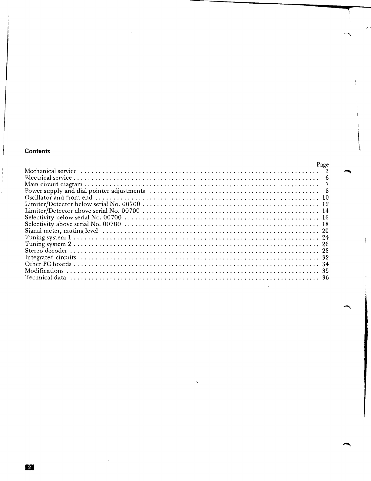
Contents
\
'
i Main
I
Mechanical
Electrical
Power
Oscillatorandfrontend..
Limiter/DetectorbelowserialNo.00T00
Limiter/DetectoraboveserialNo.00T00
Selectivity below
Selectivity
Signaimeter,mutinglevel
Tuningsystem
Tuningsystem2....
Stereodecoder
Integratedcircuits
OtherPCboards
Modifications...
Technicaldata.
service 3
service
circuit
diagram
supply and dial
serial
above serial
1....
pointer
No.
No.
adjustments
00700 . . . . 16
00700
. .
. 8
Page
6
7
.... 10
........ 12
.......
.......2+
........26
.......28
........34
......35
........36
14
. . . 18
....20
.,..32
E
Page 3

1.0
1.1 Dismantling
Mechanical
service
O Top
O
Top
O Rear
cover,
cover, front
panel
rear (1).
(3).
(2).
N
O Front
O
Bottom
panel (4).
(5).
cover
Remove
rotary
knobs.
Figure
Dismantling
1
the rear
and top coaers
I
t,
-l
i
2
lFisure
t-
i
I
Dismantling
the
front
and
bottom
couers
Page 4

1.2
Dial
cord
drive
A
I
1/
Figure
1.3
cord
Dial
3
Replacing
driue
battery
in
the
tuning
memory
circuit
il
I
Ordering
No'
376731
memorY
The
intemal
not
is
data
switched
batterv
The
chaised
is
and
receivei
the
Under
will
normal
have
is
batterY
losi
off.
the
is
is switched
life
a
that
10
bY
the
receiver
the
tYPe,
off'
the
Years'
Powered
so
when
NiCd
continuouslY
conditions
of
an
storeo
1'4
when
battery
is
t
V,
Figure
4
The
tuning
circuit
t
battery
Page 5
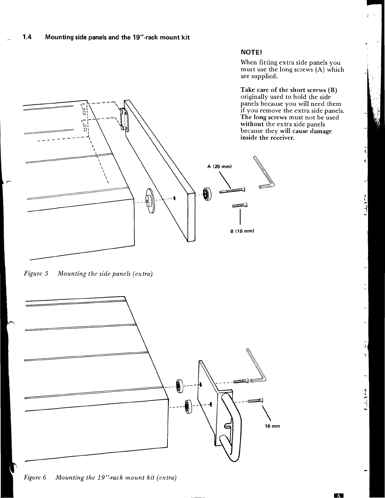
1.4 Mounting
:=--
side
\,.,t
panels
and the
19"-rack
mount kit
(25
mm)
-r*f'"'--i
NOTE!
When
must
are
Take
originally
panels
if you
The
without
because
inside
Snril'(J
I
I
I
(16
mm)
B
fitting
use
supplied.
care of
remove the extra
long
the
extra
side
the long
used to
because
screws
the
they will cause damage
receiver.
the
you
must
extra
screws
short
hold
will need them
side
panels you
(A)
which
screws
the
not
panels
(B)
side
side panels.
be used
Figure
5 Mounting
the
side
panels
(extra)
S
$r
Figure
6 Mounting
the 19"-rach
,nount hit (extra)
H
Page 6
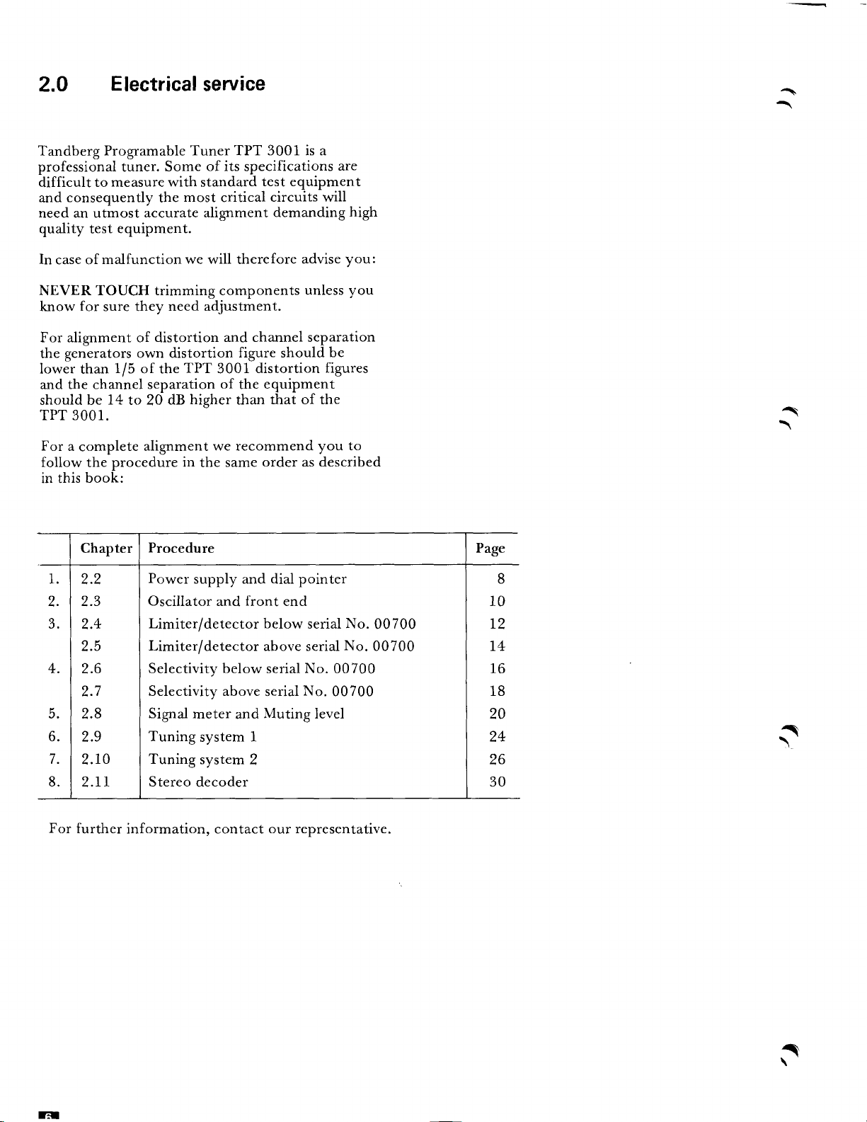
2.0
Electrical
service
Tandberg Programable Tuner
professional
difficult
consequently
and
need an utmost
quality test
In
case of
NEVER TOUCH trimming components
know
For alignment of distortion
generators
the
lower than
the channel separation
and
should be
tuner.
to measure
equipment.
malfunction
for
sure they
1/5
14
Some
with
most
the
accurate alignment
we
need adjustment.
own distortion
TPT
of the
higher
dB
to
20
TPT 3001 is a
of its
specifications
standard
will therefore
3001
test equipment
critical
and channel separation
of
circuits will
demanding
figure should
distortion
equipment
the
that of the
than
TPT 3001.
For
a
follow
in this
'I
I.
2.
J.
4.
5.
6.
7.
8.
complete
procedure in
the
book:
Chapter
2.2
2.3
2.4
2.5
2.6
2.7
2.8
2.9
2.10
2.tr
alignment
Procedure
Power
Oscillator
Limiter/detector below
Limiter/detector
Selectivity below
Selectivity above
Signal
Tuning
Tuning
Stereo
we recommend
order as described
same
the
supply and dial pointer
front
and
end
above serial
serial
serial
meter
system
system
and
1
2
Muting
decoder
are
advise
unless
be
figures
you to
serial
No.
00700
No.
00700
level
high
you:
you
No.
No.
00700
00700
Page
10
T2
T4
16
18
20
24
26
30
-\
8
a
For
further
information, contact
our representative.
3
Page 7
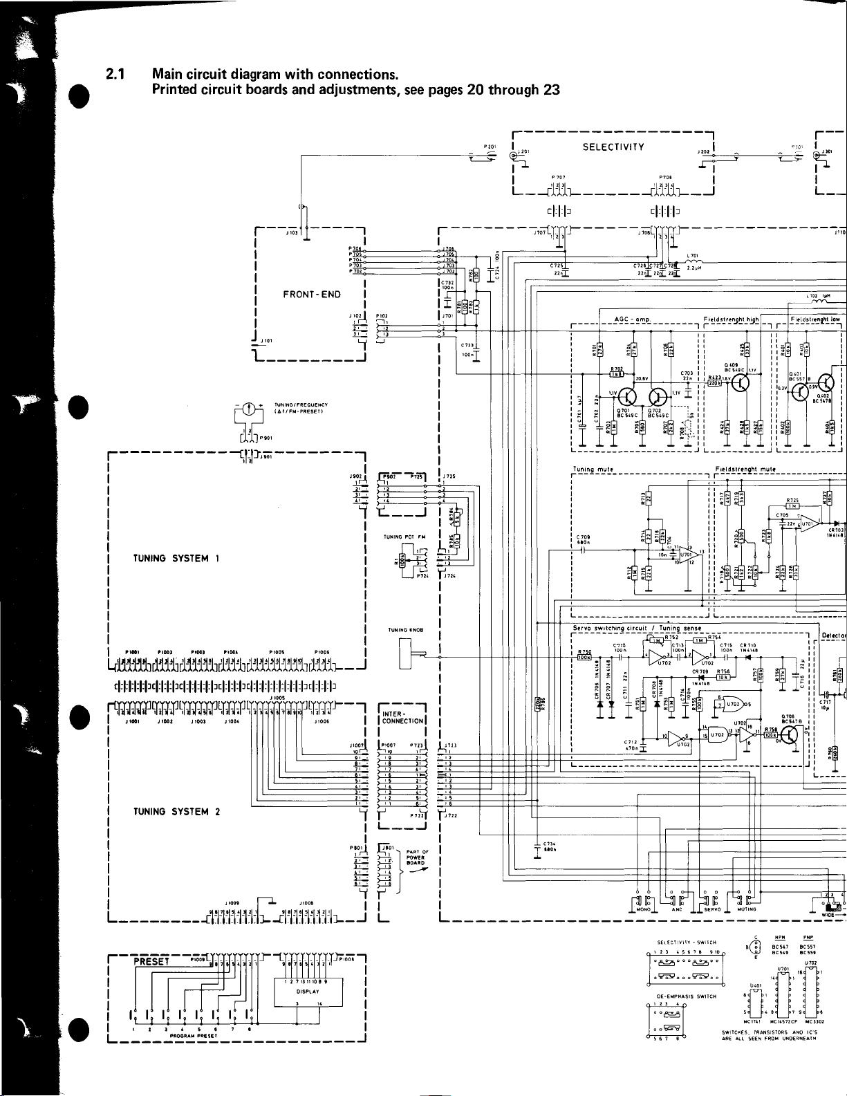
2.1
Main
circuit
Printed
diagram
circuit
with connections.
boards
adjustment,
and
see
pages
20 through
23
r----
TUNING
-
-- -- -
SYSTEM I
r
J,
________J
L
al-J],;i
-- ---
,I
FRONT-END
- --l
'l"d
+.
'1
r,:li
i-#
++
i=
'1
I
I
I
+
Ei
5
I
E;ioi-,n1
I+-----
t----t
EIEIE
Tl!
-
- - - - - -
t-
I
lt,i
lr
t,,'
:i----
I
I
I
I
I
I
I
I
I
I
I
t...
+:
.i-
lir
tft
1.,
L,:I
E
l-j,*
L -
-1.11-
cl:l:l: r
-,';fi-YY_]-
- -- - -
-
- - -
-
-rlTr-
--.1
l:l: l:l:
I
tror atool tr@t trsr Pr00! Pr0o6
klllllh
rrH{-I-tr-prI;Hilr
L - --
rll1t
rlllllb rl1lt r111111111h
rl
:l:ll:rl:ll:l:
Jr00a
?l
rl.l
61 5l
l l |l t:|'
[[Flr4:F]lr4:l:l:l:]lrrl:l:l:lr4:l:l:l:l:fl
4:f
rdr
r@, , rool
I
J
ruNtN6
- iYg ='g --
sYslEM 2
roo.
,
rooa
J
7t.l
rl.l 1 rl
el lt
{l:|l.t:|lt:|lLJt
- - -- - - - -
- J
r1-11t-
'l
.l
2l
!
rL
- - J
r
t--
F':'r
a{ |
rFt
f'
I
L
Prrrl
_J
Page 8
l-------
.:
1,,.,
==F
| ''..1li-
r-
--{
LIMITER
lAll
___
t_
----l
i DETEcToR
--d111-rL--.jl
------------------l
i
i
f
I OEgOOER
I
t;=
,7t,
|
t-rl1'11
cl:l:l:l:l:l:
P7r1
lt-d1
1111u1-1-i.h- -
cl:l:l:l:ll:
Pr'.
cl:l:l:lr
- -
-
-J
,'otl
i+r
I+
cE
tt
;- 3
ii !
f f :
.
6
r
I
L
ridii'l'-.l
r-qlll,llJlt
I
tuNtio
SYstEx
2
[-J;;";,--l
iil
lii
iil
ii.l
I t:l
I t_A
iitil
JLI
t---------r
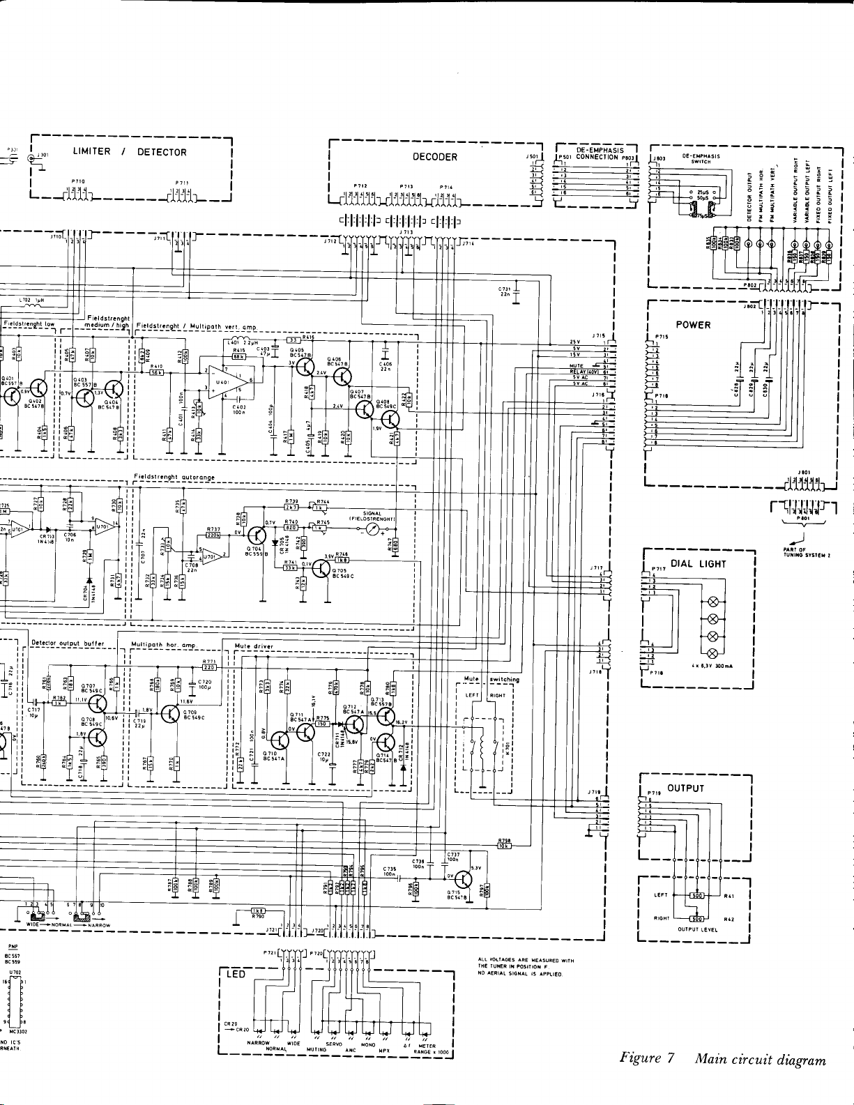
Figure
7
Main
circuit
diagram
Page 9

Power
supply
and
dial
pointer
adjustments
-'i
I lr
-l
tl
t
ilr
['
=e
=3=
z
llr
t
EROWN
l---l-".r.
-l
L____J
L_____-1
I
I
f-
__fii
I
L---J
Page 10

J
c
808
100
-1F
2
R
l
-1
-
-{
-
n
805
o
B
239
BO
o 804
B
BC 5(7
809
c
2^2
r8o2
|
-rl
t-t-l-l-l-l-1.'-
zlllzl3ltltl
-
8l-
|
+
+
a
/
a
---l
l1?v
'?B
c 817
100
2
n
cR
6V8
808
811
o
239
BD
o 810
BC 547
c 818
810
c
22lJ
I
t
B
*'T"J'
Bo,!e
rr.rv
o 814
BC 557
'$
B
cR812
6V8
reor
Power
f
Figure
B
suPPtY
]
Page 11
',1-1.4
i.l.
li
'
rsl ir!.
..
f-+#--*
,r,,*..,#.r.#
^j::ffiry
ffi1
*"#$
;^tt
??,"**'S'i
I$S$+[$F
?ffi
;[:pF
ffi,rt#,.,
1??
*,,,t
HF,"F.B FhBF,
1r?'ttil
J'-''sii1l11I
o---@]------t
qHI
lll*
*;,.
JIT
Ffr A-*
l9 19
I
JJ
tr-
i
J
l---g1..-..<
IHI [*es
ild
FFb
sJ,,
*.,,0
J +-T
rffi
YELLow
t
L le8rs
7."'
-=-*
t
ffi""I",ffi-i"l
|+l
T t
lt ,SlllllJt
1,1
i
*,f,!#i,,
.-rLsit
.--rrgs
.,0[*e*1--1"'l-l
t,,,
iLF
rffii
TlelElElE
aaaate
J301
-5..C-
T
8r-
GRErf 6REEN
t
.
T T
I
| |
flt n
llll lll I
J
lL
f"
l',
""'
i
',1,
1
''
l',,
k,';
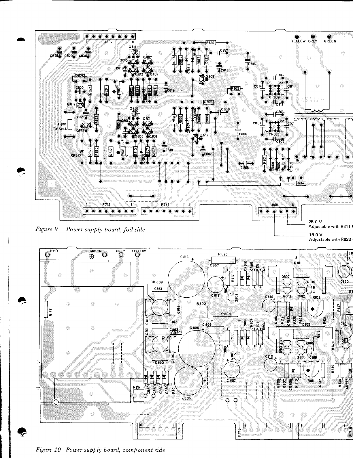
Power
supply board,
side
foil
cRoog
tG\ /
\I_l
ilr-\[']
I t( lt t;
!Ji\-11
L--*J
3
i---:Hi
s
6
L---------J
l1'{\t 1 r
I n )t tl
L J-\-.4t J t
;
c802
LLIJ--LI
-*fiHHHllr
c8t5
+
/\
/\
\ /
neor
J"
c8l2
-e&9!3
;H
0
I
\
il | I
lu!
,TT
L-
tO807 I -
ll;
U-
j!1{+
, :801 ,nn'-
uttlnilt]trf,
p
E,F,F
l[ln-Lf-
H!
i i ; ;;'rf
#stdtf**
ril
,=\TC, F,*-
t'ililffi[rN
iloero
5(IS ll
I9r-
l-,fl
-fu
s'
R8'r
3
ll
,
*_
-
LJ
Figure
10
Power
supply
$rt'*'#
board, component side
Page 12

Power
Check operating voltages at connectorJS0l:
Pl:
5 v (5.2 v)
P2:
P3:
P4:
P5:
P6:
v (5.2 v)
5
15.0 V, adjust with
40v
V
25.0
ground
adjust
,
terminal.
with R8 1
R823
1
wirh
with
Rt311
R823
pointer
Dial
O
Connect
figure
O
3
Figure
(varicap-voltages)
voltmeter
1 1
).
11 Dial
pointer
to
J705
R784-g
adjustment
(main
E
board,
see
O Tum
is in its physical extreme
I
F
e
&
pointer
Adjust
O
O Tum
meter. The pointer
90
Tuning
the
at the low
R784 for
the Tuning knob
MHz
mark
on
knob
until the
posilion
frequency
3.0 V
on the voltmeter.
for
4.0 V on the
should then be
dial. If
the
tuning
pot.meter
with the dial
end of the dial.
volt-
at the
necessary,
adjust
the pointer position.
Page 13
E
I\)
(^)
ua
\
NJ
H
jri
HF
ON
!{
R l2l
s
a
\
G
c 129 r' '
1,3-l5p
=-O
m2
7-.
;g
o
o
CL
=
P9frst
o
Fll|fr'
tr
ll
:---:l s
1.3-15P
133
C
-r r
ff62
oNi
II
r1
H
!
zxei
Ll02
IPH
Hts
Hffi
cRl02
o
lt'"
FIl
lFl
R 128
roQ
mo/
@o
T.
}!IeJ
f-+
r04
L
r-----1-f
cil2
0.68 ! H
tsc
Cll/,3.5-l5p
#lF4e
I
|
I lnq
------.
Cl13
s
l2P
ON
R
Page 14

I"'
-
q
103
BF 245 C
118
c
2 3.5V
c 120
c]l9
t'10I
56p
Cll2
12p NP0
C1l3
l2p N150
Cl15
22p NPo
Cl16
6p8
CllE
lp5
Cl20
Lr0?,
Lr0r,
r09, L I I l,
108, L
L
L 105,
',106,
L
RESISTORS
N1500
N750
Pl00
Lll0,
MARKED
+
NP0
12P
Mc110
-
0300
301 sN
AN - 0400
301
-
0300
301AN
WITH A DOT
ARE MET.
FILM
I'/.
t
A
A
c
140
ln
108 CRl09
cR
204 BB
BB
RED
RED
204
cl45
ln
cr46
1op
Ll12
lfH
--f
{l
al ol
@-T-
sl
TT
tl
c 149
l,
n'l
A
!
;
A
t
t
Page 15

-
.*#
lcn'otJ* n
q$*H$
"mllh';
,
*tt,
db?r'
q'l
cr07
-.-ll-.
etl
"+s
J
cr09
*,tts
cl08
.-lP
r
l-jl
tl
,rl.l
J rO2
*-$,ffi*"
.l
F++ +".ro,i};
*ffF
.@
ldl"Hr*
rrf52
r-;=.+
S@ta'L1:r-
'.tEH'+6
TEf
I
+FFFffiM
-,
/
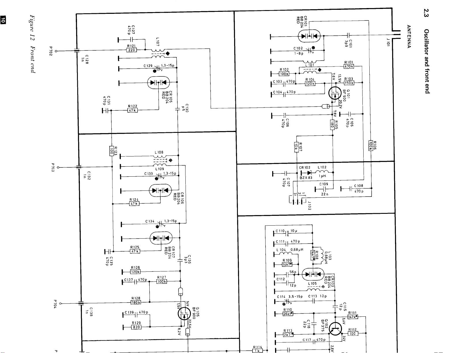
Figure 13
:XWil,,il
:r. ):,l'l'ii
QHdilfill
--'-'
-il
Front end board,
;
;
HA:
ffililrll
'__!
:
_
!:.*,
nQ,L
A A A - - -1ii'm$
;,;'__1,._t
;
.,':_
-1'':-lF**-+#'ii
]f-----.'*
-l,ii-
tL.Hi'
ffffig
side
foil
'sf+
,J,.,r.G
'#sn..,..
ll s ll
rrr'=n=,,.,;i ll
'H!l-ljill
liliii
A,;
ll
ii=fl$ii.n?EEf!l
T5
T-:iil
G-ii'UO-]T5tT#:ii=
nllffirqfttll{$ruil
ftll,ft
,-,ell
-tj-
.:l_:i
.*
rF,*
An
r
j_lL_s-'l_-__j
1;-Er<
=-
1
il,[-F*il
'.?,,
ii
ir,t il;i
,,---.
t*
ft
-rr{-iil5;
=;*1,#::
a(m;i
-il;rt--AJi';
n
ll
T.n.'ll
t,
ilg
#,un
;vTi\:
-#!!il$
Ho"'
J5?
cl28.t-
,!.il{ililil"I1 !H,
Figure
a,
Front end board,
14
component
side
.,,,r1
tt n.l;}it*ii
Page 16

Oscillator
O Conne ct
0.5 mV/75
O Connect
FM-Multipath
tuner.
O Set
O
90
105 MIJz,
The
the
O
The
trical
signal generator
oscilloscope (a.c.-mode)
Bandwidth
the
MI{2,
adjust Li05.
adjust
cover must be
oscillator adjustment.
center
sinewave on
ohms,
frequency
t
Vert.
selector to Narrow.
Cl14.
on the
the
to the antenna terminal,
kHz
75
output
dev.
at the
Front
indicated
is
oscilloscope
End
to the
rear of
box during
by
a symme-
(figure 15).
the
Figure
15 Symmetrical
sinewaue
Front End
O
Connect signal generator
0.5 mVi 75 ohms,
O
Connect oscilloscope (d.c.-mode)
FM-Multipath
O Adjust
During
to max.
the adjustment
Vert.
d.c. level on the
maximum, then very
until no
90
105 MHz:
further
maximum is obtainable.
MHz: L101,
Ll11,
C102,
L107, L108,
Ll06 (osc.
C129, Cl33,
CI44, C124
To
obtain a
adjustment with
(105
MHz) in
symmetrical curve,
Ll05
the oscillator
to the antenna terminal,
t
kHz
75
dev.
output.
the curve
slowly sink again.
(osc.
(90 MHz)
circuit.
to the
oscilloscope.
go to
will
Adjust
L109, Ll10,
amplitude).
C134, CI43,
amplitude).
make a
final
and Cl14
a
Page 17

2.4
FROM
J 202
Limiter/Detector
c 302
22n
below serial No. 00700
o 301
BF
o
BF
I99
302
I99
c 303
22p
-;T
ol
3l
22p
cR 304
AAII9
NI
oa
oo
cl
-I
ST
3I
L 301
---- --
r
ll
L-------J
FT
(Jl
-T-
6l
(Jl
L 304
pH
l0
305
L
l0y
22n
c 320
27n
c3l8
22
I
22p
vSzl
2ti
H
-l
<i
o
ol
o
";T
3I
J
-T
;l
(Jl
cR
309/ 310
2x lN4l48
F
I
o<
oO
N
I
c3l3
22y
o
0
(J
T
I
c3r5
azn
Il*
c3r6
100
n
-
o
6
J
I C lrA
f
4
I
Figure
Limiterldetector
16
belou
serial No.
F
(9
z.
t!
F
v)
o
UJ
L
00700
c322
22n
I
N
('
2
uJ
v
F
a
g
tl-
Page 18

t
V
3.5
q
30/.
BC 549 C
c
325
22n
t 68p
I
L
T
I
L 308
J
-1
307
cR
MBO 201
K 'Zb
c32s
-Jl-+
p
330
q
ls
;l
'|
N
O
RESISTORS MARKED WIIH
ARE
A OOT
CAPACITORS MARKEO WIIH
A OOT ARE LOW
MET. FILM I'l.
NOISE/LEAKAGE
n
309
L
I
r
I
-'l
I
T
:
.t
P711(4)
AFC
REF.
IN
ol
rl
{l
_r_
oT-
NI
ol
rt
€l
-T-
{l
ol
;T
ol
ol
I
i
l
Page 19

t
??l
IHqffi$ i
*-lri Y
1&*
?
Itr33
I
w
ll.*
dl.{
c 325
?fr
?T1
:l
r?
olT
tgtkbf
pa.
tgl3a
tgj
-/t.
L\- a
a
a(tr
ffi
o3o4
r?
r +{,,,
IA
f-t l- |
l'l
tptl9
'o,J
R
,R.f
d
'T'i
frr
ol
l9
t+l
r
HH
.l
lHl r
THI
J
q-?crrz
-,0u1
/
3?0,,_+
'11'.tr
rafss!-*= rT ,
l3ll
j
Srrr--erfir
?
.l't-l
c32r
caB
?f 3.n.
1 ^" HI..:1,.
pucl
19
{ | *i
"
u30r
?c'o .
T+
t
+
Tgo
{
..{Fricrtr
o'
al...i ltE
I la
I
e
(r_mr
.lr!
c 310
Figure
-l
Limiterldetector board below
17
serial I{o. 00700,
side
foil
cr?r
e0 ,r, iJiJi*
Er's
: | | .P
ttlt;:l:I
U
|
i;[]r'r;Ail llli
i'l
Tot"?,.r"3$
=
! | to I | |
,i
ll l'-l ltlt?
_cR3o6t
N
3
i
d'5
q3o6
- rl r1?,,h - -
UU Uttv1-1U s,'
:l:'3'l\
ooo:oo
rrCgUJVAEE
Figure
*
18 Limiterldetector board
below serial
No. 00700, component side
t@l_.r\/
,;
Page 20

ITI
'?l
LII I
illHl.
J E,J? I
t= |
af*rl
I
02
tl
.t
._l
L im iter/Detector, d.c.-reference
I
I
O
Connect oscilloscope (d.c.-mode) to
Fl\{-Multipath
Pull
O
out signal plug
(see figure
l9).
Vert.
terminal.
P201
and d istortion
on
the selectivity
the
box
Pull
O
O
O Shortcircuit
out
interconnector board
figure
21).
Connect a d.c.
P71
l, pin 4
board,
see
figure
millivoltmeter
(strap
next
21).
the
strap to
No. 45430
(range
R786
to
ground for
on the main
(see
100
mV)
a second.
to
I
I
I
I
O Connect
signal
generator
to
(see figure 19).
J201
_l
;,til
:!as I
ol
ilq"l
)
|
Figure
O Tune
500
1 kHz modulation.
O Set Bandwidth
Fine-tune
O
on
thus found
adjustments.
Test
19
the generator
pV
modulated mono t 75
the
oscilloscope
the
is
P2O1
,-----
points
approx. 10.7
to
selector to Narrow.
generator for
(figure
now
used
symmetrical sinewave
20).
for
the
* UOt
MHz,
kHz
The
further
dev.,
frequency
Figure
O
O
O Adjust
O
O Set the
21 Test
Adjust L308
on the
Connect an
M501
oscilloscope.
Put
figure
t
millivoltmeter.
on the decoder
L309
back interconnection
21).
75 kHz,20
points
for
slightly less than 5 mV reading
oscilloscope (a.c.-mode,
board
minimum
for
generator
mV.
modulation to
10.7
board No.
(see
MHz
5 mV) to
figure
on
45430
19).
the
(see
Figure
O
Switch
output to
O
Set
20
Symmetrical sinewaue
off
the modulation and
mV.
20
Bandwidth
selector to Wide.
set
generator
the
O
Connect
Fixed
O Adjust
figure
O Check the other
O Reduce the
O Connect the
Output terminals.
Adjust
O
sinewave
position
Put
O
box
distortion
Output
L307
0.006%.
L301 for as clean
back the
(see
terminals.
for
signal level
oscilloscoDe to one
possible.
as
and
screw the
signal
figure
meter to one
minimum distortion, typical
channel.
to approx. 5
and distortionfree
Start
core
plug P201
19).
of the
prV.
of the Fixed
from
an inner
outwards.
on the selectivity
Page 21

Limiter/Detector
Jg30r
above serial
Tl,"
c 339
,rf,
No. 00700
cR 30r
MB D2OI
Figure
Limiterldetector
22
aboue serial
No.
I
z
U
E
o
U
u
00700
Page 22

| 68p
a1-
T- la
-f-
| <t>
-aJrl-
I
L
l)
I
a
-J
32e
I
-1F
p
330
RESISTORS MARKEO
A
ARE MET. FILM
DOI
CAPACITORS
A
ARE
OOT
WIIH
I'l.
WIIH
MARKED
NOISE/LEAKAGE
LOW
:
1l
=
;T
lr
rl
I
o-Jol
"L
-{
l
P711(41
Page 23

^
I
? ? r? ?
I.I-II? I
It mtu|-l | - | |
JTEIiIEPHI IE]Bir J'
TLITr T
l9{,f
+:Prtp,Si
I rrtf;rlil t ??
-L.t,t
T
rilEJA
?r?
q
-?crrr
+#ffihd
t*] r'*i*T I
?
!-
3*,
rm.,l*
I -
Hl.ryffi
I
a
-L
I8*'
l3l
tgh
tE-
fTctoz
J
-lffiqIfffi:Fi1
J , Hfut+H?H HIe
I
It"Jtbi
o301
Jt
1....-l
4 P7l0 l
Figure
A.
Figure
,\
/
Limiterldetector board aboue serial No. 00700,
23
24
Limiterf
detector board aboue serial
No.
side
foil
ll *r)
*;'1
ll
-,
*tit..trltl"ail
rr Al llr.: H li;U
ll iutj'!afd=
lli s
pf;t=filjiirHii
ii
"r
ll
tt
00700, component side
?'?
3A
-cR306
.!,
6-10,,
E
.'
,,i,i
rt)? i
*
qi-
pE
,
.
flO
tl,+
Page 24

L i m iter/Detector,
d.c.-reference
and d istortion
O
Pull
out interconnector
figure
27).
board
No. 45430
(see
I'l
ld"'l
LI
ftctor 1
'l
I
L_l
]T'r\
,'rl
83 l
'xfl
I
rl:cl.J
I
in'l
)r-r
I
tll
nril
,r#'I
*-l
ti:
/
::
.,:. . .
O Connect oscilloscope
FM-Multipath
Pull
O
O Connect
O Tune
out signal
figure
(see
Figure 25 Test
the
pV
500
modulation.
Vert.
plug
25).
generator
signal
points
generator
mbdulated
terminal.
P20i
to approx.
mono
(d.c.-mode)
on the selectivity
toJ201
t
to the
(see figure
10.7
kIJz dev., 1
7b
MHz,
box
25).
kHz
d.c. millivoltmeter
O
Connect
P711, pin 4
board,
O Shortcircuit
Figure
O Adjust L308
on the
O Connect an
M501 on
a
figure
see
4543a
Test
27
millivoltmeter.
the decoder
(strap next to
27).
ground
to
strap
the
points
for
slightly
oscilloscope
board
(range 100 mV)
R786 on the
for a second.
[m
(see
mV
figure
less than 5
(a.c.-mode,
main
reading
5 mV)
25).
to
to
O Set
O
Bandwidth
Fine-tune
on the
found is now
thus
adjustments.
Figure 26
O Switch
output to
O Set
Bandwidth
selector
generator
the
oscilloscope
Symmetrical
off the modulation
mV.
20
selector
to
for symmetrical
(figure
used
sinewaae
Narrow.
26).
for
the
and
to Wide.
frequency
The
further
the
set
sinewave
generator
O
Adjust
oscilloscope.
O Put
figure 2 7).
O Set the
+
O Connect
Output terminals.
O Adjust L307
figure 0.006%.
O Check
O Reduce
O Connect
Output
O
Adiust
sinlwave
position
Put back the signal
O
box
L309
interconnection
back
generator modulation to
kHz,20 mV.
75
distortion meter to
other
the
signal
the
the
terminals.
L301
as
and screw
figure
(see
for minimum 10.7
board
one
for
minimum
channel.
level
oscilloscope
for as clean
possible. Start
the core
plug
25).
distortion, typical
to approx.
one of
to
distortionfree
and
from an
outwards.
P201 on the
N{Hz
No.
45430
the
of
5
trrV.
the
inner
on
the
(see
Fixed
Fixed
selectivity
rtr
Page 25

2.6
Selectivity
below
serial
No.
00700
c212
22n
34{0A(6POL)
cR
+
207
12x
lN4l18
CR2l8
wtoE
NORMAL
NARROW
A
25V
OV
0v
B
OV
25
25V
V
0v 25V
25V
OV
25V
D
0v
6@
25V
I
c2t3
22n
c228
22n
Figure
Selectiuity
28
circuit,
below
serial
Ilio-
00700
Page 26

W IDE
'+
202
cF
3125N
((POL)
2t8
c
22n
2.tv
Nld
of
:T-
-7V
cF 203
(4POL)
3r25N
c 221
c22t,
22n
cR 205
BA2I.L
E<
o@
{s
I
NARROW
*
l-*l
'?I
--Tt
l---Tt
FFI *',?t' $El FFl *',i'"'
YI 77I
l-ll-
1 | t-r t--T
hlg;i;,I,,, | $lalg;;f,U= |
-*@-l r-d@ |
,l I lsl ll
L il;]
trql
ll
I IMJ-A
iI.
L-Tiizos
lsre
REO
ilti t ilil I
.13
I
:l
;I
trH
I.
I
t***i'i
':":{
czrs
.1of
Rl
3t
JaL
t
*l
El
rl
Nl
El
I
r
tN
t{
l'
I
+
NARROW
220
cR
84241
I
@l
dlc
NId
-I
T
CR
221,
BA21t
8A244
:--l_
oT
-rSl
'l
Nl
Nt
dl
EI
cR221
BA21I,
al
rl
lJ c237
22n
:l
;l
6l
st
-l
I
I
t-
I
I
la
IA
zl
^^-^
El
ztn
N'
N/
LR IZ5
BA2LI,
Nl
NARROW
-<-
c
EL
-J-
C2
-T
22
ii,
c2t
@l
dl
I
221
I
cl
LO
n
Nl(
o_l:
T
wroE
I?[X6,i
[JRi^.
I
I
I
s
,frl
Page 27

,-.
,F.
ffL lF$++$F:l+$
++4+
M$%m+ffi-+#$:
*M*ffiww:*NWdfffi
:,
*ffi'#
foil
*
t r*4j i*ind'r
IH
#iltalTTtiii'b@
*$$fi
;ffi4
+a$tr
ffi
?1h.m,"%
side
tffi
-r.-@*x6s
c:to;.-----..-
W
$**
i
--.
I
ffi
*Gj-*-
pffi4
* f,+ffi
LI\;J#"J.[I;,Slmt"#THT#j*
Figure
29
selectiuity
board
below
serial
No.
00200.
a
Figure
30
selectiuity
board
below
seriar
+
No.
00700,
component
side
a
Page 28

Distortion
in Wide
position (6-pole
filter)
Distortion
in Normal
O Connect signal generator
MHz,0.5
98
modulated in
O Connect oscilloscope
FM
Multipath
O Set Bandwidth
O Fine-tune
the
oscilloscope (see
Figure
31
mV/75 ohms.
stereo + 7 5 kHz, 10% pilot
(d.c.-mode)
Vert.
terminal.
selector
the tuner
Symmetrical
for
figure
sinewaae
the
to
to
symmetrical
antenna input,
Right
Narrow.
31).
channel
to the
tone.
sinewave on
O
Connect
98
modulated
O
Connect
FM-Multipath
O
Connect
O
Set Bandwidth
O
Adjust
distortion.
O
Check
signal
MHz,
oscilloscope
distortion
CF201,
distortion
0.5
AGC
O
Connections
O
Set
O
Screw R708 fully
figure
O Increase
reaches
signal
32).
the
0.1%.
generator
generator
mV/75
in stereo.
Vert,
meter to Fixed
selector
CF202,
Tolerance
in
mono. Limit
as
described
to mono.
counterclockwise
signal level
to
the antenna
ohms. Right
!
kHz,10%
75
(d.c.-mode)
terminal.
Normal.
to
CF203 for minimum
<
0.05%.
channel
to
Output R.
0.06%.
above.
(see
until the
distortion
terminal,
pilot
the
tone.
O Connect
O Set Bandwidth
O
Adjust
distortion
selector to Wide.
CF101 (Front
minimum distortion (on
and at
symmetrical
figure
O Check in
well
Be aware
I
end circuits is
limit
the
same time
sinewave on the oscilloscope (see
31).
mono to obtain best result
as in
stereo.
Distortion limit
that a correct
essential to
figure.
meter to Fixed Output R.
End,
figure
distortion
the
maximum d.c.-level
32)
for
meter)
in
mono as
and
0.04%.
adjustment of
the
front
obtain the distortion
Adjust
O
to
O
Connect
O The
R708 until
0.05%
voltmeter
voltage
AGC-regulation
O
Check
generator
that regulation
signal
cF1o1_
R702
/t
hA
.v f-
il
I
\t_
R708
R7
+/
||-.]
I
the
to
at R702
and
should
fall
level exceeds
m
|ilililtJr_
tilililtffi
distortion
R702
(see figure
be
when
regulation
does not
0.5
falls
32).
V
with
20
no
starts.
start before
mV.
=
nr
+il r
'illt
oo
the
fl
u
Figure
32 Test
points
Page 29

2.7
Selectivity
above serial
No.
00700
cR 203
8A
2((
,rI
artd
,'T
rC2
t22
cR
+
20?
cR2l8
12 t
rN
1la8
W
IDE
NORMAT
NARROW
A B
25V 0v
0v 25 V OV
OV 25V
c 0
0v
25V
25V
25V 0v
I'
T
lc
2t3
2n
ltt6
ttn
FI
Nl
ol
Figure
33 Selectiuity circuit,
aboue
serial
No.
00700
Page 30

w r0E
+
s
+
NARROW
zzn!
205
0
cF 202
3125N
(4PoLl
C
22n
c24
cF 203
3r25N{4POLt
o
cR
221
8A244
NARROW
<-
\
I
o{
a<
oo
cR 205
BAzLL
N
-_l-
I
@l
ld
-f
E
T
lriie,r
I
205
cF
SFE
MJ-A REO
J_
219
C
-f
22n
-l_
c
2r.0
-T
2?n
c 23t,
"f
22^
225
cR
-T
&
rl
ol
+
N ARROW
cR 220
BA
2T4
cR22l
EA2LI,
gA
2LL
[JR[^'
I
{t
Page 31

,-.
f-_ll"sftrs*
I \ | i;-€P, r*r ,ffi l'flllo,'
| \- I HI?T fr?H'{HF FFi."'
I \ |
l.
. .*oBl- 1 o.^t ^c-.RI
1r
jJuiiai-iuiq1til-',#
lH
8'd"\;u'iiiialul
THHHSHHHH S-+F=i
tfl
J*(TT
Lz
;;
I'hhT
\t'.f
cz*-r.(r-zor
A
nl
T?- H dt.,uTffi{*,
A
1
"'-'JJf
.-----------{
EF
i'-@-;#E&*
T
fl1
tl-t
CF2O3
I HH1H
It--_lII:rr T
HI
"
CF&z
IHHiH H H
FH#-iffiikd:'H*'t''
+&"nm-$,;ffiry-:*1
;ffil
il'ffi.eftryg:'-=-
eiffi,,
A 4,,* rflg*T*'
t';{TT"hHbHFH
l
gi,tmt.#
I-.lTl;#
ff*
I
I
i
$ffi6 ;
HqH HTql
Imt"#
1&foffi;s .
iT"ITl**iir.-",
T ? Slr^'iil
&zog>y o--lR-iTI---{
.--@q-'-;-@--.l
S"Iffi4
oa2
1.;l dr_il1_
p7o8
'
.-%;
|
1
4
Figure 34 Selectiaity
--[=]-
&101
J
^-n
(D
l0l
*J4
board
aboue serial
eF,o,
E
lE]E_
#frau;utt.*i
I
T
i'l
ir
No. 00700,
foil
side
,ftiltlifril[l{-{,f*[l*$
{,
lL],].#i -""
'F*9,,
[z's-$*cot@,, 1 1*",prrrT-
,ii;f--..,_
|
-
-
H H H
)",u*fufi
-
$U
l*
R22rtJ
:-------
______
i *,r,
*rF#
,'-'i
r
InT,#,.,1*--ltiii
nzr'rH
R229+R238-
'*;,p_Y
e.'-*
ps{ra
nzffid/s\rnza!=j-
-:::ff-
".r,u.,,i;.fr=S
o
.rrr
--t-==--J-:","\
ii
czzs|
*IlLl3'^'lJd
c"5
-rr*=|
g*:a*dle
fr'ffi
n2!er----r-
?.-,-Efr ilf , *utl ul6#
iA
Kzor
-
---r"'"'cz:s-3;;fr']
-fi=
T?
,,1
l/\ts
g
9F
i\
t'D
Figure
Selectiuity
35
board
aboue
serial
l"lo.
00700,
component
side
Page 32

Distortion in Wide
position
(6-pole
filter)
Distortion
in
Normal
Connect signal
O
MHz,
98
modulated
O
Connect
FM Multipath
O Set Bandwidth
O Fine-tune
the
Figure
0.5
mY
in
oscilloscope
the tuner
oscilloscope (see figure
36 Symmetrical sinewaue
generator
175
stereo
Vert. terminal.
selector
to
ohms.
t
kHz,10% pilot
75
(d.c.-mode)
to
for
symmetrical
the
antenna
Right
Narrow.
36).
input,
channel
the
to
sinewave on
tone.
O Connect
98 NIHz,
modulated in
O Connect
FM-Nlultipath
O Connect distortion
O Set Bandwidth
Adjust
O
distortion.
O Check distortion in
CF201, CF202, CF203 for
generator
signal
0.5 mY
oscilloscope
175
stereo. + 75
Vert.
selector
Tolerance < 0.05%.
AGC
O Connections
O Set
signal
O Screw
figure
R708
3 7).
described
as
generator
fully counterclockwise
to
ohms. Right channel
(d.c.-mode)
terminal.
meter to
to Normal.
mono.
antenna terminal,
the
kHz,10%
Fixed
Limit
pilot tone.
to
the
Output R.
minimum
0.06%.
above.
mono.
to
(see
O Connect
O Set
O Adjust
minimum
and at the same time maximum d.c.level
symmetrical sinewave on
figure
O Check
well
O Be
end circuits is essential to
limit figure.
distortion meter
Bandwidth
CF101
36).
in mono to
as in stereo.
aware
selector to
(Front
distortion
obtain best result in
Distortion limit 0.04%.
that a correct adjustment
End, figure
(on
Fixed
to
Wide.
37)
the distortion
the oscilloscope (see
obtain
the distortion
Output R.
for
meter)
and
mon<-r
of
the
front
as
Increase
O
reaches
Adjust R708
O
the
signal
0.1%.
until the
to 0.05%.
O Connect
The voltage
O
AGC-regulation
O
Check that regulation
generator
voltmeter
at R702
and fall when regulation
level
signal
level
until
distortion
R702
to
should
does not
exceeds
the
figure
(see
be
20
start
0.5 mV.
distortion
falls
37).
V
with no
starts.
before
the
Figure
37
Test
points
Page 33

2.8
Signal meter,
muting
level
r-------
FRONT-
END
lr
II
t,,'
J,
L
=
I
I
I
I
-,iil t2s
fl,-
ri1 -
Tlr
I
I
I
I
I
I
I
!
1,,,
Y',,,
l----
kl'1111t rl-t1t
- - - - -- -
TUNING
Ploor
Pr002 Proot Proor
SYSTEM I
rl1l1lt rl11t rl-11111111% rl11-t-
-
/T\
n | /-
t-l
-'i-?l| | | lProl
a[],;i
IUNING/FNEOUENCY
+
lat/FH-PrEsErl
-- ---
pr005
pt006
- --l
-
I
,ro,
J::
l1J
,!r:
1
J
__J
;lEft
rffl:l:l:lrcl:l:l:lrrl:l:l:l:l:lr4:11:lrrlJ:l:l:l:l:l:l:l:l:cl:l:l:l:
{,Hfi_J.jr
!-tl,T,T,IJ_p
I r'oo' ,roor rroot Jrou.
T_;H.Ij
T_I_H
S.rvo swrlch'ng
- - - - -
- - - -
i
i
;o'.^
0?0r I oror
Tunrog
cz'o
'00"
circuit /
; J] fl
E
s.nsc
-:r"-f
q;i
.-
lc?r3l - lc7r5
lN lrooilN lr00n rN.i.0
- - - - - - - - - - -
t--si
cR?ro
- - - I - i
j:l
rrl
I
-o:'!
cJ
g-o-u g:'_
IyltJl
TUNING SYSTEM 2
t:
r: r:
r:
L----i"ou*3="'---
Figure
Main circuit
38
EI
t: t: t: I
diagram
r Pr0o3
IP
T.*;T
t=l
y.7-:&
I -'i- ::
|
:' ! - - - - -'--V=j
Page 34

;;;-,;,;;;---l
lo
1'1r- - - -- - -r1-1-t1r- - -l
P?rl
',2l
.t
t
llllt-
rl:l:l:l:
-:- - ---'l
,Ti!
- - - r
- -
rr-1
=
l-,
;;
t-
- -'l
l------------
i
I
I
I
t+R
I
P1,z
I
st
: r rt x.r
r-flltllllullllll{
cl:l:l:l:l:lr
oEcoDER
5t 6t
Gt r il n.l
cl:l:l:l:l:l:
(\
1,.,
L----------
j111111il
r-ql-J,l-lJr''l
\
-
1
Ptol
)
*T
"(N
C NPI
"*t ".r.
E
f"',r I
L---_-__-J
r---------'r
ouTPUl
"?,i
G\
r
_J
-''l
I
or,*.",. I
L--------J
PNP
ALT VOTIAGES AR€ VEASURED
IUNER
IHE
io
€RrAL STONAL
I
POSIIION F
II
WIIH
rS AtlLrEO
fri
Page 35

Jt01 J?os
oo
aDJ.
(
T0 3.00v
R 7861
J
o
706
rflst\
/E\
E,\
I
a
L
3
--] tEt I
I I-.-n
rl Fl lllllE
.i_J
rrr
-ll9l.--
,,r^,I
IL '
l-'l r"Ar-ilsl
!-E] lV,,FY-'
li-]-On
's:t;Q;:u'
,tl
j
,:,";
,n
"'[--rl
$
rut,
c?r3
Efr+MN
,ililr;T
ol@l
cna
il
,,1
I
I
I
rF
.E
II
nn
lilt
T-J L]
:::
c?t+
r-1nE+
1tilo
o
LJ
l,E,
il+l
1J72t{l
T__l,
ill|l
rltll
L_lr
*
,
ct16
l-lt
ttl
1",
li
lol
t3
e
Figure
39
Main
board,
component
side
Page 36

Signal
meter
I
I'l
ntil
lltt'"
;,
I I il+
signal
MHz unmodulated,I
Bandwidth selector
R413
generator signal to
Meter
:+
[=
ct3l
Connect
O
Signal 98
O Set
O Adjust
meter.
Increase
Turn R733
marked
|iIIr',fil$Fq
R745
meter.
R733
Meter
R744
on the
,
,1.'
_#;(
*["F
f
ii..o"j_
|
O Adjust
Signal
O Turn
marked
Signal meter
Adjust
O
figure 1
generator to
(B) for 1
(C) fully
Range x
(F) for 1000
(C) counterclockwise
Range x 1000
needle
(J)
falls.
for a meter
dial.
the antenna
Normal.
to
prV
reading
I mY
clockwise
goes
1000
pV
reading
just
deflection
1tY
until
terminal.
ohms.
175
on the
ohms.
5
17
the LED
off.
on
until the
and the
lights
to the
Signal
the
LED
g
4ryff
-"fll'*
sr,'^'^?.'I-
tr'l='e a.)r'l llllll
j.-*il.*r+.il.il'H
tl'ffilr*,,i;h|--
f[?*:, ,,,r=
ufrl*$
x ?0r
| / \','i;J-'
I lrlr-
L _ JI
I
g
I
-'t:tJ t
!t tt | 6?0r otos
sl ll l - .,;-,
-,
RTaa
F llr
Irl ^l- U r -
nF-l'
16---;;;-
'
s
'$+=Q[&ilI
l
r-
J,,.
:
Muting
O Connect signal
O Connect
O Set the
O
O
O Adjust
O Set
O
O Adjust
Level
MHz,
Signal
3
98
pY175
terminal.
Press
Set Muting
(signal
Set
(signal
ohms.
oscilloscope
Bandwidth selector
Muting
the
R718
is let through).
generator level to
the
Muting Level to position
the
R720
is let through).
Level to
generator to the antenna
!
kHz
modulation,
to
position 3.
disconnect
disconnect
Fixed Output
the
Normal.
to
mV.
1
the
1k.
the
muting
muting
(G)
(H)
20
switch.
to
to
terminal.
8
Page 37

*.[
fi?-.1f,-czzet
.;ii+
@':zoe
flzzz
tt&r
.
. . ol
15
l
?
t-
latlafaf
llr
l8
r
r r r
J7l6
T,
1lll11,
AfiH$
'#;
""RF
iTI
l
Jffi$*ry
*srTrl
-gHHHq
I
r----___llI
13
",r;
I '
l?l
I llrrtrt
I
-,,,.,,
,
.,,,
'
ldrfid$1dr
I
?Y??Y
ft,fJt
,f+
;.4ifi
?llElEl
,,+
Jt
+*r{
#f''.HR?
r-Y"q
t
I
r,o,
8{*-J.l
?
a 1,,'E
Y t-t
i[
rrer-osrn? ? ? | | | |
??t?
dr
I
'{qqHruK
H$$$H
-.':?H$
r T L,,iY*i* $,*'
ll'11111
F=;-l
,-:---"i'{i
i=-itft*'-';
da f------l /tsj
a
L{
l.
.
, .i
a
q
,,,d
Fl^",t*li
J
l
$rH
c?o€ c?os
a{b
t1?? 1?
AA+A +,L
l$llsllsl lsl lpllxl
FqFts FP
attl lJ
Jtaa
ooo
Fl-;l
TW-I
-=_!j93_-l
ilo r r rlr
oooo
P72s
AAF,teHA
-q*lA.H$H$H+-#
tttttl
!lalJJr
i{li,|
)
I
I
??
lt
IFl*
r+r
l€
l"*
I
I
I
I
I
I
*
.f---I
.l
F
!l"o'g
rl
P
.l
b
tol
bt
1_
tFt
T
+J
1
I
I
ji*?
?Til.EIA
,l
''$ l,=lT frjrlr.
lH$it *ir i"
'j'.JF
d''Fiar
FFiF I
1#dvfrri
|
|
|
| --.-..-----.----
,
Fl-;-;
r ll....l
1 tTTATHHHH
1 il-r
lra]Tm
m Lr f@l!
I I 1,, r
,rto
.
;;ll
TllTl,,,*.
lt
? ?, r
Figure 40
@
Main
board,
foil
side
Page 38

U
o
t
I
I
I
lt
a'
?
t'
I
j'l:
l-t
-F
1
O Or-{ O o O Or-'O O
@ W
@
ooHooooHoo
?????,
Ail lI
L?IIII
f-
lr
#l
I
r rtii
AAI+I
tl? ? I
tFt
.. ol
r rzrf r
+,.'
A
I
Y
t,,.\*T l*.|:?T'
a.
t'J[ff
I t I t ,o'"'l
T
r-rrflr I
T-
JBI*T
l{
?
,l-fn
T'"
I
a
f$** r
Y't
? ? t I
I
6i
l'Y
l0t'1
-*.--.----..-..
-!-*------t
la
g.*,
,'p
i
l
I
,,,lti
LJI
|
g^")
o.l
.
0lr
l
I
1
I
I
I
t
{
?
I
I
I
I
I
I
[--F[l
=
EZL.
1
c
\y
v
H*FHryH
.oroKo
'rov
i
I
g,'['-l*,
?l r t
FH+
foY
-+T
"gF.
1
Hl
t-
J
aa
rg,"
i'r:
a
rfil
a
,rr+
ra{
I
:
F
?,
I
?
I
I
I
I
t
+
I
t
?-
t'
?
t
I
t
lnl
EI
t{l
t@l
-r
t
t
?
t
rFe4
l
I
t
+
I
I
Inl
t{l
t@l
tpl
-'ltri
t$
aI
t
Aod€
rorrQ sorrQ
t
orTov
at
Page 39

2.9 Tuning
r
system
1
1N4r48
A:U902=MC11572
:
B
U9O3 = Mc 11s72
:
C
U9O1 = Mc 1101 I
=
r.1 /.8
I N
cR 903
D = U9O5
E
F
MC 11023
=
U90? = Mc 11016
=
U9OS = MC 11016
Figure
41 Tuning
system L
R926 R927 = R92o
|-.ort
|
- Cgl I tln^
-
t,,q
ogos
BC 569C
R93a
R937
cR911
BA 219
Ll</^-F
-
d
cR9t3
atnS
tN
cR9tl
lNlla8
Page 40

MC
MC
MC
MC
MC
MC
F
G
l(572
115?2
l10t I
r10 23
r(016
t{0r6
..ll
llllf,
+i[;'i"
Proo3 Jl.
-tf
T].
I
6l
l
-'l-'l1e'oo.
.AAJ--
-..rl-^4,
ilrl'
-.']
Pt005
G
fi
Page 41

,}.
[-,] ,Afrf''' 66,ffi,
l:lqtti
l.lu'l
tttl
?
?
t
I
,Tgtlrqinl:lF,FFT
I
I
I
J
JJf
t
I
;if'i i+r I
I
I
-L
I
rt
ol
H:[J]tl
I
al
qa
I
1
-:1--"'L-Bl
JJ"''?'
rr:ifi:
? *':1,,,1
***lrr
I |
I 1,,, r--rrHF
iliHIFI_JdHTil
t'
F$t
r'[lT
'[:l
,l:
""'
l"*
I
Figure
)
tv
Tuning system 1 board,
42
side
foil
$ilft,[]rufl
l___.tAl
-t tl
-'r
dl
e?l
i=ililft
le
j3
-l
i*
lffi,u[
l,g*'nln,l,,,i,r ll',
ll
lli#,jl,HFF'HF'P
itlLJpi
li,ii
rli
i*?
il-+wi
I
i'i
i
i,il
'rl
rii
I
illi
l**
tl
;,'T*nlilf-iuil{
sr\
ztt
#il.)"il[Jf*r'!
n A
I lel l
| |
I |
I
l--";l ll ll ll
+
[J:!
rA rllr
Elldi
'il*
(rl,Hlil-i
f-ryLq
I I
:----=
,'\
PU
_uE
broi
'
Al lr+
;rr**!?"
I
iill
\./
_osol
le
a&
i;Ll
i
i
*T"'
laUl*lal
'rr
!i
;,:
,LJr
i
!
Lr
TlililFffil
I't;*
tlF
/
Figure 43 Tuning system l board, component side
TUNING SYST. I
Page 42

The tuning system
Preset
dial
t
tFl
t{t
tEh
rI
?
I
t00!
t{h
c9l7
t
I
a
1
f
I
a
T
I
*
O Connect signal
Signal
O Conncct an oscilloscope
I
I
Multipath
O Set Bandwidth selector
Place
O
of gravity
O Tune
the oscilloscope.
O Adjust
Tuning
O Check that electrical
with physical mid-position by
ptugJ901. This
O
O Adjust
98 MHz,
the tuner
for
R947
meter needle.
position
R947.
Press
the
R1002 (Tuning
symmetrical
generator to
!
kHz
75
(a.c.-rnode) to the
Vert. terminal.
to position
horizontally to
fron-r influencing
98 MHz and symmetrical sinewave
obtain
of
the
Servo
to
should
needle.
button.
sinewave
mid-scale
mid-position corresponds
not influence
If
system
on
antenna terminal.
the
modulation, 0.5
Narrow.
prevent
meter
the
disconnecting
necessary,
2,
oscilloscope.
thc
the force
needle.
position of the
the
adjust
figure 44)
mV.
for
on
O
Set the tuner to
O Press Program Preset
Press
O
O
Touch
O
Store
Adjust R937 for pointer deflection
MHz
88
lower dial.
mark on the Tuning/Frequency
sense
Turn R752 (figure 44)
increase the
88 MHz on
1.
Program.
the
counterclockwise
touch sensitivity on the Tuning
knob.
O
On some tuners the pot.meter
by a fixed resistor. Increased
increased sensitivity.
main
dial.
to the
meter,
to
R752 is replaced
resistance
will
,qive
ooo
-l
:-'
o noo
,-
l.q +
il| to
ll ll ls
ililtE
ill
o
6
I
al
I
A-
ot*,
R757
q
I
control
generator
the
on the
6
the
o
Figure 44 Test
Press
O
O
O
Program
Press
Store Program.
When the programming is finished
frequency
frequency for
oscilloscope. Tolerance:
points
Preset
deviation
symmetrical sinewave
1.
by adjusting
20
kHz deviation.
If
O
the
to
inaccurate
the AFC or
detector.
deviation exceeds
adjustment of
d.c.
the
reference
kHz, this can be
20
Tuning indicator,
the
voltage in the
due
rEl
Page 43

2.1O
Tuning
system 2
Lr;
lool
-T
ol
6t
J
zEz
c
T
I
I
I
I
r r002
E
a
t-l- :YT
AFC
CURRENT OUTPUI
u 1002
UAA
IOOS
I
I
caPASrToRs
I
lne
I
MARKEo wtTH A
NorsE/LEAKAGE.
Low
ooT'
I
Figure 45 Tuning system
E
l00r
s
SIORE
PRO6RAM
2
7 l0 6 5
2
9
I I'uoo
4 lr 12
u toot
Mc r6i29
I 3
5 15 r
,1
ls
I
9
l0
3
U 1003
14426
Mc
64
14 13
12 ll
16
lol
B.
II
-l
I
t,
Page 44

l-.,,0i7;,*-LT-
'l---"ill'
r00l
Q
BC 448
7t,
4t
I
I
I
t5
r4
l s r
13
t2 ll I
ul0o4
uc,rr3o
2 3 6 7
16
ro
t--r-T
J--T
o
7123
8
.L
"
o
I
13
u 1005
MC l(51
15 I 12
1
l4
11 10
cR 1010
lN4ta8
'-1
I
r00s
I
---
|
T
1008
f
e
J
(a
Page 45

'ff1 'f:'*l
''ifl
? ' ?E ,ar?T
. _
f
;:l n
,\
?'
J
Figure 46
+J+*1
I
0r003
ll
A-
TI
tc
r009
ot?
t006
e
al
?
ls.
ctogra
I
Tuning system 2 board,
I
?
I
I
I
a
t
T
F
t
1
rgr
tol
Y
J
foil
e
'T-
rto'
!:
:
lctotg
+?
lta
.l
Ll@2
1t
r*r I
tl
II
side
+l I ll I ll
fr'-
i i t Ha? f-tj+I
'i IrHBBF
f
I
?rgl
|
\.
IF
alc
I
j
F lffifi:
''-l*r,,,,
.-*i;;*H
tl lll
l*Hffiqlirqry
F.lil
HH
1 H 4
::ljji$'#T
'''F''-:l
:l
t r r r &e'$T'"'tft''"''[il
FtH
JHIHHHHH
L:,,46 all
T''",:11''
T'lr.ti'
:::{|;::Fr
.,,,o1,
I
TTTI
'El
I
,,*lil
Jr007
r
gE
tA,T\"4 ,51
Et tRl ll tfil i
E3,J#UH"
$"
tr r'r =tr e[--]
El
I
5t
/l l3
6\
I
rro$
E{
---'r
X)e
5\
t.
)r )s
5t
or
I
I
ol
lil 16
/6
/t\
6\
il lF
ELJ
LJ*
iiii lel lsl liiEH
iiri ifi Yi i,,lt'E
r-Ell'X
i) tHt il( )
i.,'*
i*,Tt*- 1g:T
EH
L
'i
=-
i
A *
-J ll.bd
P
i
i i*+l
Jloo5 Jl00t
llri
nnnn
El
il|ill
;t
|| 11 lt I
UUUU
.
E'E'E'
oZtq
TUNING
A.
in', ivtfr
Ui(Jl
oiST
19A
l)
t--_-."I
|
|
,rt \*(
ii|,ol'
ll*-J
I
r
r
=l =[l , nEl
;l I :l
rJ r+
@
!
;
Eillt
-T
il|il
rTp-r5-r
oa
;
l*l
i
I
|
|
BATfERY
SYSI
cl
Rto02
f
ot
I i us'
I
cl
cl
2
ct0r0
J-
t-tl lg
\-/
I l.. r'l lll ri
I
---'
rl*+il.l,
{,'ZYfttbtl*.,s
1rt\
)t
{
I
'
Er-----f
AA
ll lc
ll ld
-T
t-
'
/
.',00,
"oo'
r()
I
r
cl00?
/\+
\.(,-
-l-rlgl..-,,-rs\
I
eir
I lll I
i l*_JJ[__],
iflJ
w.;H LIF
'
F
*"-1;
3*ABl
HL
ffi
|
i
s*,.
ll
ll.
H
T
Figure 47
Tuning system 2
board, component side
Page 46

2.11
Stereo decoder
Es
c52l
220n
-A
______:l
Figure 48
Stereo
decoder
Page 47

(612
C6r6l C
I I I II
o 615
I
$H
!
a
AiE XEIAI FtLt
i0rsE/LEAXAGa
Ait tow
t
r/.
.}
Page 48

19
kHz
oscillator
O Connect signal
Signal
0.5
O Connect an
FivI
O Set
O
Use the
the main dial,
sinewave
r
Figure 49
O
Switch off the
O Connect
the leads
way out
O Adjust
counter.
generator
98 MHz,
mV/75 ohms.
Multipath
Bandwidth
Tuning
Symmetrical
of
R574 for 19.00
!
oscilloscope
Vert.
selector
knob
and
on the oscilloscope.
modulation.
frequency
the counter
to
tuner.
the
the antenna terminal.
to
75 kHz modulation
(a.c.-mode ) to the
terminal.
Narrow.
to
the
kHz
in to 98
symmetrical
M502. Arrange
to
shortest
on the
to tune
fine-tune for
sinewaue, mono
counter
mono,
MHz
on
possible
frequency
O
O
Bandwidth
Set
for
Tune
the oscilloscope.
Figure
O
O
O
50 Symmetrical
Connect AC-voltmeter
read
the output level, approx.2.2Y.
Connect a selective voltmeter (1 kHz bypass-
filter)
Press
to
Servo
MHz
98
Fixed
(AFC).
selector to
and symmetrical sinewave
Output R.
Narrow.
stnewaue, stereo
Fixed
to
Output L
Adjustments
mlnlmum
voltage
Fixed
at
Output R
on
and
Mono/Stereo
O Set
the signal
only 10%
O Set
T
the
O Adjust R577 until the
O Set
the
O Connect
filter)
(1
mV)
Increase
O
O Adjust L502 and R506 altemately several
to
obtain minimum
Stereo
separation
O Connect signal
Signal
G
I kHz,0.5
O Connect oscilloscope to the
switching
generator in Stereo
pilot
tone, 7
Bandwidth selector
Bandwidth selector to
a
selective
an oscilloscope with
or
to M501,
generator
the
generator
!
MHz,
98
pV.
N{PX
voltmeter
use M601
and
signal
kHz.
19
kHz
75
to antenna
modulation, stereo
mV.
to
indicator
level to
FM-Multipath Vert.
terminal,
position with
Normal.
Narrow.
(19 kHz
high
sensitivity
for ground.
500
terminal.
lights
bypass-
pV.
times
up.
L,
O
Switch generator
O
Connect
Fixed
Bandwidth
Narrow
Normal
Wide
the selective voltmeter
Output
L.
Adjust for
R617
R615
R619
ANC
Connect signal
O
Signal98
1 kHz, 0.5 mY
o
Connect
filter)
to
Bandwidth selector to
o
Press
o
o
ANC.
Adjust
R510 for
generator
IvIHz, t 75 kHz modulation, stereo
175
a selective
Fixed
to Stereo R.
to
minimum
voltage
at
Fixed Output
antenna terminal.
to
ohms.
L
55
60
70 dB
voltmeter (1 kHz bypass-
Output
R.
Norma].
30
dB
channel
separation.
ration
dB
dB
R,
Page 49

Page 50

FrF
.,9
;,1 6<r$i
f',&*,,
rT&,F
il
:[
c?98
;
*tF.
I
la En<
r.--
reqill ffi \p;-*bu$b
,+l
T Fl
mp#pqrild#;[l
mffiBq-llldffilil
TT
;l
;:,.8
ii
:i
c 5,1'
qF
:66Hfi6fi
F*JFF+HH+
",,r,Tft,#'&ffi
*
r.*.
+
^,rEEE-anr [--;rr
i
-THH6TT*'
t f,T
.T.#,,'
j
1
s
es+bb' $;'*,r'lPin,F I
r"'
F'T r*''',*::L' I
r,ffi.
F
H
r
H
S'
si
g*
;L
;HHHHHH
H#j,'fu:#,,
t
I
I
I
I
€r
It
ll
lt
tl
-T.
rvl
ll
ll
tt
tt
'li
tlt
ig'
s
et et
r
t-l tl
it.]qj
-
r'l
rtt
.ttI
rill
itl
tl
tl
ll
, ,t[l
lilll
r'lll
lill
ill
r
rll
I
| / \o | |
l-(.Jr I t
16 ll
!6 ll
l"ftA I lil
t-_-J
G
r:-t
rll
lt{
rlll
rtll
lrll
iill
E
r.--r
lll I I to
L-J
LJU
t
I
I
I
I
I
I
E
ir
I
tt"l
i
I
I
o
I
il
ri
I
o
I
l()
t
UJ
o
I
lgfH:
Q
I
I
I
;q,H
I
r lF
i
l,n
ll
M50?
I
Figure
51
Stereo
decoder board,
foil
side
"
-il"ilI
oq6
dd6
cee
o
A
\P
'
1?
Qto-o^
S'^^)^*
L^-")
-
Page 51

2.12
lntegrated Circuits
u301
TDAT04T
5 6
y
->
_>-
Null
Offset
I nvt I nput
Noninvt
u401
MC1741CP
I nput
ToPvtEw
NC
Vcc
Output
Offset
Null
5
1
3
10
contror
1
.'4__J
contror2
,.rLl__l
u501
/502/601
MC14066CP
l3
i I
5
-
I I
/907/908
Vgg
Vss'Pi^
u505
MC14013
_+>*-
r3
I
_D*_
12
-#-
It
-D"-
=
Pin
lr!
7'
Voo- Pln
Vss
u506
MC14069
=
Pin
10
12
tl
7
Vgg = Pin 16
-
Pit
Vss
ll
2
B
u507
MC14015
I
2
I
3
4
5
t1
12
t3
Vp9
Vgg
-
Pin
=
Pin
7
6
I
9
12
t3
u508/904
MC14011
OFFSET
NULL
NOil
Vgg.Pml
V55 . Prn
^t-
5
(?r
-l
al
(r.)-1-
-l
-L_
"J
u901
MLM311
@
u905
MC14023
u906
cA3140
Page 52

f_l
tr
tl
2
a
Out I
IL
T-J
f--t
tf
f-t
IH
tr
071908
l P--3
---/
-r---\
| )r
_L--J
| ,r-
.
Pm
V00
.
Prn l
V55
i08,/904
cl{,011
14
Out 2
Out 3
Out
ro
r1
VOO
Vss = Pin
a
=
Pin
14
A
I
Output
tnouts
J
al
vEE
u503/909
MC1458
---D*-
,
--)"-
o
u--f)-u
-----1____-/
7
ro--ft-
vcc
B
Outpur
r
\
"o"r
l8
'
I
7
u504
MC14007
t
;D=,,:$>--*
s
vCC - Pltl 3
8
12_-_>-11
------r\
14
I >-r3
----1___-/
15
Voo ' Pin t6
.
Pin
Vgg
u701/902/903
MC14572
8
u702
MC3302
;: E;
36 do
t
l
2
3
5
7
8
9
u1001
MC14429
BANO 156
OSCILLATOR
BANO SXIP
18
1?
16
AOORTSS
1q
t4
13
fuit
1 1
10
a
Page 53

2
MEMORY
COPY
clocK
OX
SUPPLY
ao0Rtss
CHANCT OUI
ABCDDI€EI
\r-L-rrJ
ADOR€SS
INPUTS
CHIP
S€LECT
I
2
a
6
7
I
DATA
OUTPUT
DATA IilPUT
u1003
MC14426
)
2
.
l
2
CXIP
$lrcr
u1004
MC14430
A.
Bb
Cc
od
LT.
t
8r
LEO
DISPLAY
n
t
,
U
]
t
u1005
MC1451 1B
t:a
J
tl
5b
tz
::
:,
ta
,f-
'-L:.ro
.LI,
Voo
Vgg
ltE
6
=
-
Pin 16
Pin
8
q
Page 54

J
I
1
J
I
1
r
I
{
-t-
I
-1_
2.13 Other
PC boards
a"raJ_*ati
!;
-
907/
t24
56B9?3-
v00
vs!
J508,
[c11
Figure 53
Figure
Output connector
Output connector
54
BLUE
REO
ce
:,t3
9.!
115y-
9:
o"cce
BLACK GREY GREEN YETTOW
=
230V
board,
foil
side
-i
-:'
803
J
board, component
l
side
o?a;rjr
,d'
rEh
%je
li#t;
t
L'o
UT
GJ
ri\
,UT
\':/
v-@
t0
,O=,
:
lJ
I
55
WHI
oL
#
Figure
BRO\IVN
Figure 57
Voltage selector
side.
foil
TE
t;t,
Power
foil
switch
side
board,
board,
Figure 56
Figure
58
Voltage
component side
Power switch board,
component
selector
board,
side
a
Page 55

4.0
roquirements:
Power
consumption:
Power
Outlets:
Dimensions:
Tech
nical
sPecif
ications
Width:
Depth:
Height:
Weight:
118"
lbs
!
(43.5
(35.0
(
8.3cm)
(7
ks)
2301'115Y
34W
Ei".t Ouror,,
17
13314"
3114"
t5.3
100/o,50/60
Variable
cm)
cm)
Hz
Output,
FM-Multipath
Detector
and
-
output
according
Technical
tEEE
Tuning
Antenna
Usable
Data
185,
Std.
range:
imPedance:
sensitivity
1975
(measured with
;dd?ililil'ln.iti'itY'
ANC
filter
noise
With
iignat
Signal
Muting
Muting
Stereo
Stereo
fi"qu"niv
Oistortion
Distortion
noi""
i"
noise
to
threshold:
hysteresis
thtoshold:
hysteresis
r€sponse
at
at
Distortion
lntermodulation
t'a
Measu
Caoture
iji."""t
lii"-tnate
Spurious
lmage
I F-risponle
RF intermodulation:
AM
Stereo
Subcarrier
19
38
Signal
Signal
at 65
.oA.
[nt
1
red
ratio:
"r,"nnel
"r,"nnel
resPonse
resPonse
suppression
s€Paration:
suppression:
kHz
kHz suPPression:
meter
meter
ratio
ratio
dB
3
dB:
3
dB
50
dBf:
65
dBf
distortion
5oo/o,
in
k4z
selectivity
selectivity
ratto:
balanced:
ratio,
ratio:
Product
autorange
autorange
at 65
at
3o
quieting:
: Stereo
15
o/o
ratio
ratio:
10
85
dB
Hz
Mono
kHz
:
channel
dBf
,0'5
dB{, 5
15
to
:
mod'
t
1400
l:
ll:
IHF-T'200'
to
f
ilter)
notch
separation:
mV:
mV:
kHz:
50%
kHz:
200
kHz:
: Mono
$::"X
Mono
Stereo
Stereo
Mono
Mono
Stereo
Mono
Stereo
10O
10
1OO
10
Mono
Ste
100
1975
kHz
1
kHz
6
kHz
kHz
1
kHz
6
kHz
reo
1
6
10
-
87.5
ohms
75
Wide
0.65
1
.0
11.0
5.0
95
82
92
1uV-3mV
(11.25-81.0dBf)
5uV
Q5.2
+0.2
+0.2
<
0.1
0.1
Hz
O'O3
o.o3
0.03
O'O25o/o
Hz
Hz
kHz
kHz
kHz
0.04
o.o4
0,1
0.1
<
0.1
<o.1
0.4
> 135dB
> 135d8
135
> 120
0.3
1.0
',l08
MHz
unbalanced
(
7.5
uV
(1
1.25
uV
(32.1
uV
uV 125.2
dB
dB
dB
dBl)
-0.5
dB
-0.5
dB
o/o
o/o
o/o
%
%
%
0/o
o/o
lo
0/o
%
dB
3dB
dB
30
dB
dB
72
dB
60
dB
70
dB
60
dB
50
dB
95
dB
95
dB
-'100O
uV
-
3000
mV
dB
dB
dBf)
dBf)
dBf)
dBfl
uV
mV
Normal
1
(
dBf)
6'8
uV
0.6
(
dBf
o/o
%
dB
dB
dB
-
-
dBf)
dBf)
dB
dB
1000
3000
)
10.3
uV
0.9
(32.1
uV
1.0
(25.2
uV
5.0
dB
95
dB
82
dB
92
1uV-3mV
(11.25-81.0d8{)
5uV
dBll
125.2
-0.5
dB
+0.2
+0.2
dB
o.2
0.3
0.06
0.06
0.055%
o.o25%
0.05
0.05
O.25
0.7
O.15
o.15
1dB
12
90
135
>
> 135
135
72
60
60
50
45
95
95
> 120
uV
0.3
mV
1.0
-0.5
%
o/o
%
%
o/o
%
o/o
%
dB
dB
dB
dB
dB
dB
dB
dB
dB
dB
uV
mV
Narrow
uV t 8.2
0.7
uV ( 9.3
o.8
(32.1
uV
1.0
1
(25.2
uV
5.0
dB
95
dB
82
dB
92
1uV-3mV
-
(1
1.25
5uV
dBl\
\25.2
dB
+0.2
+0.2 dB
0.9
0.8
o.'12
o.25
0.45
0.0357o
0.08
O.2
1.0
2.O
O.5
0.8
3dB
40
135
>
> 135d8
135
72
55
55
40
35
95
95
>
120
uV
O.3
mV
1.0
81.0
-o.5
-0.5
Yo
o/o
%
%
o/o
7o
o/o
%
%
o/o
o/o
dB
dB
dB
dB
dB
dB
dB
dB
dB
dB
dB
-
-
dBf)
dBf)
dBf)
dBf)
dBf l
dB
dB
1000
3000
uV
mV
l
l$
li
-
Optional
-
acrylic
Black
-
Attachment
Extras:
walls
side
for
sets
f
reestanding
for
installation
units'
racks'
19 inch
in
Tandberg
TANDBERG'
Alternatlve
53.
Box
A/S,
The
Post
European
Office
Ospecif
without
N-2007
ications
notice.
Kieller'
sub,iect
are
Norway
Prinied
to change
-
I
1771
NorwaY
in
-
Part
81
bY
6lTandharn
714174
No'
Reclamo
A/S
A/S
1Oe1
\
 Loading...